This will attempt to explain a method of designing a wooden thread of any size; a necessary step before making a tap and die.
(1) Choosing a Thread Angle.
The first step is to decide on the THREAD ANGLE that you wish to use. Many threads in metal and wood have 60 degree thread angles. I prefer a flatter angle of 80 degrees. This makes threads that are less sharp and less vulnerable to chipping. They are also a little stronger (though slightly less ‘efficient’) since the forces created by the angled faces of the threads tend away from shear and toward compression as the screws are tightened. Wood is weak in shear (longitudinally) but strong in compression. All of the presses pictured in my website have 80 degree threads. I will show how to design 80 degree threads using inch measurement. The same principles can easily be applied to other thread angles and to metric measurement.
(2) Establishing a Ratio of Thread Height to Pitch.

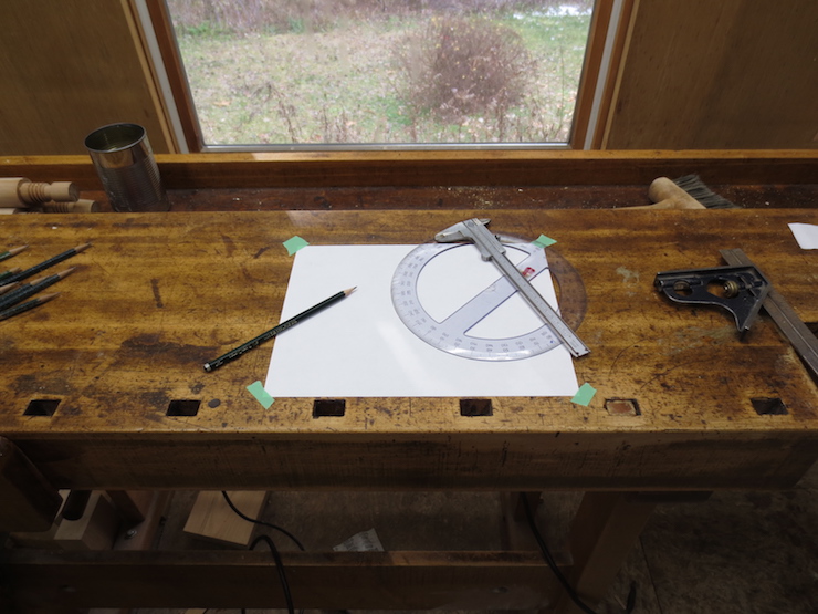
This triangle represents the geometry of a single thread in cross section. Measurements taken from this simple drawing can be used to calculate a wooden screw and matching nut of any size and pitch. I’m sure there is a way to calculate the ratio between the height and base of an isosceles triangle but since I don’t know the math I use a protractor and rule to make an accurate drawing to measure from. Making the drawing large insures that the measurement will be more accurate. To make the drawing you will need a PITCH (here represented by a somewhat arbitrary 8.000″) to use as the base of the triangle and the THREAD ANGLE (here 80 degrees). I took the measurement of 4.775″ directly from the finished drawing using a vernier caliper. This establishes a ratio which can be used to calculate the BASIC THREAD HEIGHT of ANY thread with an 80 degree angle.
(3) Using the ratio to calculate Basic Thread Height.
Using 8.000″ as the pitch of this imaginary thread (which would make a truly huge screw) works well for my collection of thread pitches. These include 4 TPI (1/4″ pitch), 3 TPI (1/3″ pitch), and 5 TPI (1/5″ pitch). All of these can be divided evenly into 8″ so determining the basic thread height of any of these is simply a matter of dividing 4.775″ by the appropriate number:
8.000″ / .250″ (1/4″ pitch) = 32. It follows that 4.775″ / 32 gives a basic thread height of .149″ for a 4 TPI thread.
8.000″ / .333″ (1/3″ pitch) = 24. It follows that 4.775″ / 24 gives a basic thread height of .199″ for a 3 TPI thread.
8.000″ / .200″ (1/5″ pitch) = 40. It follows that 4.775″ / 40 gives a basic thread height of .119″ for a 5 TPI thread.
(4) Truncated Thread Height.

The next step is to calculate the TRUNCATED THREAD HEIGHT. It is best for the wooden threads to be ‘flattened’ on their outer edges. Having sharp threads (internal or external) serves no useful purpose and makes the threads vulnerable to damage. Subtracting 1/8 of the basic thread height from both the top and bottom (1/4 total) will give the truncated thread height. This leaves 3/4 of the full dimension so multiplying the basic thread height by .750 will yield the result that you need. For example the truncated thread height for my 5 TPI thread would be .089″ (.119″ x .750 = .089″)

The drawing above shows how the original full sized thread and the truncated thread fit within the context of a threaded hole.
(5) Establishing Major and Minor Nut Diameters.

The best way to design a new thread is to start with a TAP HOLE for which standard tooling will be available. For wooden screws a Forstner bit used in a drill press is the best approach. These are available in a wide range of standard sizes. Choosing the actual hole size gives the MINOR NUT DIAMETER and adding the truncated thread height (twice; once for each side of the hole) will yield the MAJOR NUT DIAMETER. (“Nut” here refers to anything that includes a threaded hole even though it may seem odd to refer to a press jaw as a “nut”). The minor nut diameter is fixed at the dimension of the hole that is bored to receive internal threads. After a thread is cut into the nut another larger diameter is created. This is the major nut diameter. Using the 5 TPI thread as an example the minor nut diameter is .875″ (7/8″). Adding the truncated thread height (x2) yields a major nut diameter of 1.053″. (.875″ + .089″ + .089″ = 1.053″).

The drawing above should be imagined to depict a screw passing through a threaded hole. The narrow spaces between the pairs of outlines represent the necessary CLEARANCE, ‘looseness’ or ‘play’ between the parts.
(6) Sizing the Screw for proper Clearance.
The next step is to determine the dimensions of a screw to fit the threaded hole. The screw needs to be sized to create a sufficient amount of CLEARANCE. Clearance is needed to insure that the screw and nut can work freely through all seasons of the year. As humidity increases in summer and decreases in winter dimensions of the wooden parts change slightly. The pitch of the screw will remain constant (since wood doesn’t change dimension longitudinally) but the pitch of the nut will change since wood swells and shrinks significantly across the grain. Both the screw and the threaded hole will become slightly oval during parts of the year. Creating enough clearance will prevent any of these fluctuations from becoming a problem.
To create clearance the screw is made with major and minor diameters that are smaller than those of the nut. To calculate the MAJOR SCREW DIAMETER subtract from the major nut diameter the same amount as was used to establish the thread truncations; 1/8 of basic thread height. Again I will use our example of the 5 TPI screw. 1/8 of the basic thread height of .119″ is .015″. This needs to be subtracted from both sides of the major nut diameter to establish the major screw diameter. In this case 1.053″ – .015″ – .015″ = 1.023″. This will be the outside diameter of the threaded part of the wooden screw.

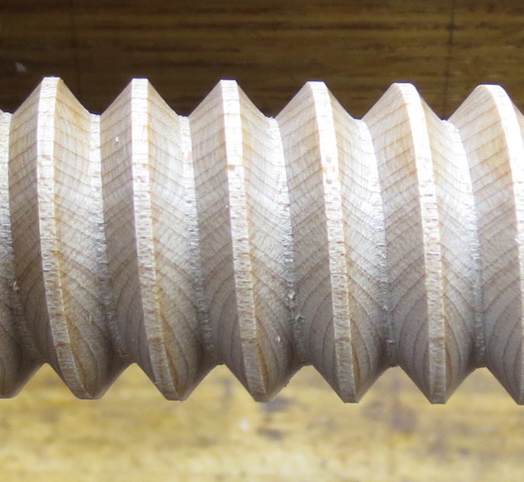
Making the screw and nut to the above dimensions will still leave room for some adjustment. I prefer to tap holes deeply; leaving only a minimal truncation on the minor diameter. You can see this in the photo above; only a narrow margin of the original hole remains. Internal threads are practically indestructible and only subject to wear, not breakage. Tapping the internal threads deeply allows you to leave wider truncations on the external screw threads to make them stronger and less liable to damage. You can see this in the photo below. I make the cutters (both tap and die) with sharper tips (less truncated) than those calculated with the method above. It is better to have the cutters more ‘pointy’ than less. This a matter of preference; I have seen screws with threads cut to full depth with no flats at the bottom between the threads. This would have no real effect on strength for either internal or external threads.
You may be wondering about the holes that need to be bored in the unthreaded side of a press which the screws must pass through freely. The outer diameter of any custom made screw is unlikely to match a standard sized Forstner bit so the fit is likely to be either too tight or too loose. My solution is to choose the next larger standard Forstner bit to drill these ‘slip’ holes. A part of the screw shank is then turned to a larger diameter so that the fit isn’t too sloppy.
Here you can see the oversize diameters turned on the blanks to fit the slip holes in the unthreaded half of a press. The thread can never be cut completely to the shoulder so a portion of the smaller diameter must remain unthreaded as seen on the left.
