WO2016158451A1 - Knot formation device - Google Patents
Knot formation device Download PDFInfo
- Publication number
- WO2016158451A1 WO2016158451A1 PCT/JP2016/058486 JP2016058486W WO2016158451A1 WO 2016158451 A1 WO2016158451 A1 WO 2016158451A1 JP 2016058486 W JP2016058486 W JP 2016058486W WO 2016158451 A1 WO2016158451 A1 WO 2016158451A1
- Authority
- WO
- WIPO (PCT)
- Prior art keywords
- arm mechanism
- arm
- holding member
- needle
- knot
- Prior art date
Links
Images


Classifications
-
- A—HUMAN NECESSITIES
- A61—MEDICAL OR VETERINARY SCIENCE; HYGIENE
- A61B—DIAGNOSIS; SURGERY; IDENTIFICATION
- A61B17/00—Surgical instruments, devices or methods, e.g. tourniquets
- A61B17/04—Surgical instruments, devices or methods, e.g. tourniquets for suturing wounds; Holders or packages for needles or suture materials
- A61B17/06—Needles ; Sutures; Needle-suture combinations; Holders or packages for needles or suture materials
- A61B17/062—Needle manipulators
Definitions
- the present invention relates to a knot forming apparatus of a type that forms a knot by delivering an end of a body to be ligated, for example, a thread-like member.
- Patent Document 1 As a technique for forming a loop on a body to be ligated, for example, a thread-like member, and fixing the body to be ligated, the thread-like member is wound using a thread anchor described in Patent Document 1 made of metal or synthetic resin, for example.
- Patent Document 3 proposes a technique for welding filamentous members to each other by heat or ultrasonic waves.
- the thread-like member that is fixed by twisting, fitting, or welding these thread-like members has a problem in that the bonding strength and the tightening property are insufficient as compared with the thread-like member to be ligated.
- Patent Document 4 describes that a knot is formed by simply bundling two needle holders to restrain the relative positional relationship and performing the same operation as a manual operation. It is necessary to operate each of the two needle holders substantially.
- Patent Document 5 describes a suturing aid that forms a knot by performing a predetermined procedure. In this case, it is necessary to use another forceps for delivery of the thread-like member, and it has been impossible to form a knot with only the suturing aid.
- Patent Document 4 Although various devices for ligating a thread-like member have been proposed as in Patent Document 4 and Patent Document 5, all of them are auxiliary devices that support the ligation of the thread-like member performed by an operator, and a knot is a machine. However, it is not possible to realize a device that can be easily and reliably formed by a typical operation.
- the present invention has been made in the background of the above circumstances, and an object of the present invention is to provide a knot forming apparatus capable of easily and surely forming a knot by mechanical operation with a simple operation. There is.
- the gist of the present invention includes: (a) a base portion; and (b) a first arm mechanism and a second arm that are provided on the base portion and are configured to be relatively movable.
- a first arm mechanism and a second arm mechanism each of which includes an operation unit at least in part of the second arm mechanism; and (c) provided in the first arm mechanism, wherein the first position of the body to be ligated is determined.
- a first holding member that is detachably held; (d) a second holding member that is provided in the second arm mechanism and detachably holds the first position of the body to be ligated; and (e) the first arm.
- a third holding member provided in the mechanism and detachably holding the second position of the body to be ligated; and (f) a second position of the body to be ligated provided in the operable region of the second arm mechanism.
- a fourth holding member detachably holding (g) The loop of the body to be ligated is provided in at least one of the first arm mechanism and the second arm mechanism and intersects at two positions between the first position and the second position of the body to be ligated. (H) the first arm mechanism and the second arm mechanism are separated from each other, and the first position and the second position of the body to be ligated are defined by the first holding member and the fourth holding member.
- a first loop forming operation for forming a loop of the body to be ligated by the loop forming means in an held state, an arm approaching operation for causing the first arm mechanism and the second arm mechanism to approach each other, and the body to be ligated
- a first switching operation for switching the first position and the second position from the state of being held by the first holding member and the fourth holding member to the state of being held by the second holding member and the third holding member, and the body to be ligated 1st place
- the first arm separating operation for separating the first arm mechanism and the second arm mechanism from each other in a state where the second position is held by the second holding member and the third holding member.
- an operation portion provided on the base portion, wherein a position is passed through the loop to form a knot on the body to be ligated.
- the first arm mechanism and the second arm mechanism are separated from each other by the operation of the operation unit provided in the base unit, and the first position and the second position of the body to be ligated are second.
- the first arm mechanism and the second arm mechanism in a state in which the first and second positions of the body to be ligated are held by the second holding member and the third holding member.
- Away By first executing the arm spacing operation sequentially for the knot to the object to be ligated body said first position by passing the loop can be automatically formed.
- an operable operation unit is provided in at least a partial region of the first arm mechanism, and (j) the third holding member is provided in the operation unit of the first arm mechanism.
- the loop forming means operates an operation unit provided in the first arm mechanism;
- the operation unit separates the first arm mechanism and the second arm mechanism from each other;
- a second loop forming operation for forming a loop of the body to be ligated by the loop forming means in a state where the first position and the second position of the body to be ligated are held by the second holding member and the third holding member;
- the arm approaching operation for causing the first arm mechanism and the second arm mechanism to approach each other, and the state in which the first position and the second position of the ligated body are held by the second holding member and the third holding member.
- the first holding member and the fourth holding member A second switching operation for switching to the holding state; and the first arm mechanism and the second arm mechanism in a state in which the first position and the second position of the body to be ligated are held by the first holding member and the fourth holding member.
- the loop is again passed through the first position by sequentially performing a second arm separation operation for separating them from each other. For this reason, since the loop forming means is provided in both the first arm mechanism and the second arm mechanism, the first arm mechanism and the second arm mechanism are functionally symmetrical.
- a multi-stage knot can be automatically formed by a simple operation.
- the apparatus further comprises a moving member that relatively moves the loop of the body to be ligated formed by the loop forming means and the first position of the body to be ligated, and the moving member includes the body to be ligated. It moves to the direction which leaves
- the body to be ligated to form the loop is formed by moving the body to be ligated forming the loop along the first arm mechanism or the second arm mechanism in a direction away from the base portion. Can be moved in a direction to remove it from the first arm mechanism or the second arm mechanism, and the first position can be passed through the loop.
- the knot moves the first position of the body to be ligated from the position farther than the first position out of the two positions intersecting the loop to the position closer to the loop.
- the operation section forms the knot a plurality of times, and at any one of the plurality of knots, the loop forming means
- a loop that is wound around in the opposite direction around the previously formed loop and the expected passage path of the first position is formed.
- the loop forming means forms a loop wound around the planned loop of the first position and the previously formed loop in the opposite direction.
- a knot called an unresolved male knot can be automatically formed by a simple operation.
- the knot moves the first position of the body to be ligated from the position farther than the first position out of the two positions intersecting the loop to the position closer to the loop.
- the operation section forms the knot a plurality of times, and at any one of the plurality of knots, the loop forming means
- the loop formed in the same direction around the expected passage trajectory of the first position is formed with the previously formed loop.
- the loop forming means forms a loop wound around the planned passage of the first position in the same direction as the previously formed loop. It is possible to automatically form a knot called a female knot that is easy to tighten by a simple operation.
- the loop forming means forms the loop once around a rotation axis of an operating part provided in the second arm mechanism. This forms the most basic knot, which is called a single knot from a loop formed once.
- the loop forming means forms the loop twice around the rotation axis of the operating part provided in the second arm mechanism.
- a double knot which is called a double ligation from a loop formed twice, is formed next to the single ligation, which is simpler and harder to unravel than the single ligation.
- the loop forming means forms the loop twice in the first loop formation, and forms the loop once in the second loop formation.
- the size of the knot of the bottom double ligature is large, so the force applied to the ligation object is smaller than that of the single ligature, and the bottom knot is loosened while making the second knot. Hateful.
- the first arm mechanism and the second arm mechanism are relatively moved within their opening / closing surfaces, and the rotation axis of the operating portion of the second arm mechanism is the first arm mechanism. And a direction parallel to the opening / closing direction of the second arm mechanism.
- the direction of the separating operation of the members between the holding member provided in the first arm mechanism and the holding member provided in the operation part of the second arm mechanism, and the first position of the ligated body Since the passing direction with respect to the loop is the same, the first position of the body to be ligated can be passed through the loop by using the above-described separation operation, which is convenient.
- the relative movement direction of the second arm mechanism with respect to the first arm mechanism is a direction perpendicular to the rotation axis of the operable region of the second arm mechanism, and the rotation axis of the operation unit is A direction parallel to the opening / closing surface direction of the first arm mechanism and the second arm mechanism.
- the first arm mechanism and the second arm mechanism can move relative to each other within the opening and closing surfaces and rotate around the rotation axis in a direction parallel to the opening and closing surfaces and intersecting the loop.
- the first arm mechanism and the second arm mechanism are relatively moved within their open / close planes, and the rotation shaft is configured so that the rotation axis of the first arm mechanism and the second arm mechanism is the same. It is a direction orthogonal to the opening / closing surface and intersecting the longitudinal direction of the arm.
- the rotation shaft is configured so that the rotation axis of the first arm mechanism and the second arm mechanism is the same. It is a direction orthogonal to the opening / closing surface and intersecting the longitudinal direction of the arm.
- the first arm mechanism and the second arm mechanism move relative to each other in a direction intersecting a straight line connecting the connection portion with the base portion and the second holding member
- the second holding member and the fourth holding member are held via a second holder (cylindrical) that rotates with respect to the second arm mechanism about an intermediate point between the second holding member and the fourth holding member
- the operation unit rotates the second holder by an integral multiple of 360 degrees relative to the first holding member and the third holding member.
- the first arm mechanism and the second arm mechanism at the tip of the knot forming device open and close, so that a knot can be formed around the symmetrical object arranged so as to be sandwiched between the tips.
- the second holder by an integral multiple of 360 degrees, the first position and the second position of the body to be ligated can be exchanged even through a loop forming operation.
- the first holding member and the third holding member are arranged with respect to the first arm mechanism with an axis parallel to the relative movement direction of the first holding member and the third holding member as a rotation axis. It is held via a rotating first holder, and the operation section rotates the first holder and the second holder in an integral multiple of 180 degrees in opposite directions.
- the operation stroke of the drive unit can be halved.
- both relative rotations are integral multiples of 360 degrees, the first position and the second position of the body to be ligated can be exchanged between the first arm mechanism and the second arm mechanism even after the loop forming operation. .
- the second holder has a shape for guiding the body to be ligated to the fourth holding member via a position farther from the first holder along the relative movement direction. have.
- the vicinity of the second position of the body to be ligated rotates around the outer periphery of the second holder, or the side surface of the second holder (position away from the rotation axis) is ligated. Since the body can be hooked, the body to be ligated can be reliably wound around the second holder.
- the first arm mechanism and the second arm mechanism are relatively moved in a direction intersecting a direction connecting the connecting portion with the base portion and the second holding member,
- the holding member and the fourth holding member are held via a second holder (arm body) that rotates around a straight line connecting the connecting portion to the base portion and the second holding member, and the operation portion is
- the second holder is rotated by an integral multiple of 360 degrees with respect to the base portion.
- the first arm mechanism and the second arm mechanism at the tip of the knot forming device open and close, so that a knot can be formed around the symmetrical object arranged so as to be sandwiched between the tips.
- the second holding member and the fourth holding member are rotated together, the structure becomes simple.
- the second holder by an integral multiple of 360 degrees, the first position and the second position of the body to be ligated can be exchanged between the first arm mechanism and the second arm mechanism even after the loop forming operation. .
- the first arm mechanism and the second arm mechanism are configured to move relative to each other in a direction intersecting a tying direction between the connecting portion with the base portion and the second holding member.
- the holding member and the fourth holding member are held via a second holder (arm body) that rotates around a straight line connecting the connecting portion to the base portion and the second holding member, and the operation portion is The sum of the rotation angle of the first holder relative to the base portion and the rotation angle of the second holder relative to the base portion is rotated to be an integral multiple of 360 degrees.
- the first arm mechanism and the second arm mechanism at the tip of the knot forming device open and close, so that a knot can be formed around the symmetrical object arranged so as to be sandwiched between the tips.
- the relative rotation amount is the same regardless of which of the first arm mechanism side and the second arm mechanism side is rotated, the topology regarding the knot formation is the same, so the parts can be used in common. On the contrary, there is an advantage that the ligation is performed by the rotation mechanism only on the second arm mechanism side, and the operation stroke of the drive unit can be halved.
- the rotation axis of the fourth holding member is a direction orthogonal to a direction intersecting with a straight line connecting the connecting portion with the base member and the fourth holding member.
- the body to be ligated can be compactly stored along the second arm mechanism by rotating the fourth holding member.
- the first holder and the second holder (cylindrical first cap and second cap) rotate around the direction intersecting both the opening and closing direction and the longitudinal direction of the first arm mechanism and the second arm mechanism, the yarn Even if a needle or the like is attached to the end, the needle can be directed in the longitudinal direction of the first arm mechanism and the second arm mechanism. Therefore, the knot forming device can be downsized without being restricted by the length of the needle.
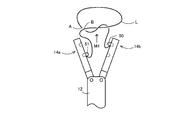
- the first arm mechanism and the second arm mechanism are relatively moved by a rotational motion such that the moving distance becomes larger as the position is farther from the base portion.
- the first arm mechanism and the second arm mechanism at the tip of the knot forming apparatus can be opened and closed like a forceps that opens and closes like a fan around the center, thereby simplifying the first arm mechanism and the second arm mechanism. Can be opened and closed.
- the fourth holding member Provided in the base portion, and the space between the first position and the second position of the body to be ligated is held by the fourth holding member via a side close to the base portion.
- a guide member for limiting the posture is included. Thereby, a to-be-ligated body can be reliably wound around the 2nd holder.
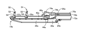
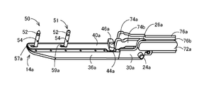
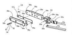
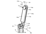
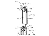
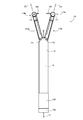
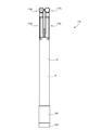
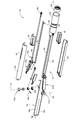
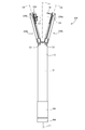
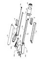
- FIG. 1 It is a front view which shows the state which the 1st arm mechanism and the 2nd arm mechanism opened of the knot formation apparatus in one Example of this invention. It is a front view which shows the state which the 1st arm mechanism and the 2nd arm mechanism of the knot formation apparatus of FIG. 1 closed. It is a perspective view which decomposes
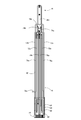
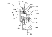
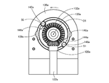
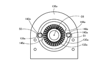
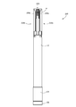
- FIG. 1 shows the longitudinal cross-section of the knot formation apparatus of the closed state of FIG. It is a figure which shows the bottom face of the knot formation apparatus of the open state of FIG. 1, ie, the end surface of an operation member. It is a figure which shows the state which rotated the operation member provided in the knot formation apparatus of FIG. 1 45 degree
- FIG. 14 is a schematic diagram for explaining an operation performed in the order shown in FIG. 13 by a rotation operation of an operation member provided in the knot forming apparatus of FIG. 1, and shows an arm separation state in which the first arm mechanism and the second arm mechanism are opened.
- FIG. 14 is a schematic diagram for explaining an operation performed in the order shown in FIG. 13 by a rotation operation of an operation member provided in the knot forming apparatus of FIG. 1, wherein the arm main bodies provided in the first arm mechanism and the second arm mechanism are The loop formation state rotated about the axial centerline of a longitudinal direction is shown. It is the schematic diagram which looked at the thread-like member from the front-end
- FIG. 14 is a schematic diagram for explaining an operation performed in the order shown in FIG. 13 by a rotation operation of an operation member provided in the knot forming apparatus of FIG. 1, showing an arm approaching state in which the first arm mechanism and the second arm mechanism are closed. ing. It is a mimetic diagram explaining switching operation which changes a pair of needles in the state where the 1st arm mechanism and the 2nd arm mechanism were closed.
- FIG. 14 is a schematic diagram for explaining an operation performed in the order shown in FIG. 13 by a rotation operation of an operation member provided in the knot forming apparatus of FIG. 1, in which the needle is moved with the first arm mechanism and the second arm mechanism closed. The arm separation state in which the first arm mechanism and the second arm mechanism are opened after the delivery (arm approaching operation and first switching operation) is shown.
- FIG. 20 is a schematic view of the first arm mechanism after the first switching operation in FIG. 19 as seen from the tip thereof.
- FIG. 20 is a schematic diagram illustrating a state in which the thread-like member is detached from the first arm mechanism and the second arm mechanism by the thread removing operation illustrated in FIG. 19. It is a figure explaining the definition of a loop using showing the path
- FIG. 20 is a schematic view corresponding to FIG. 20 when the loop forming operation of FIG. 15 rotates the arm body twice in the single knot knot forming operation shown in FIGS. 14 to 19.
- FIG. 20 is a view corresponding to FIG. 21 when the single knot knot forming operation shown in FIGS. 14 to 19 is performed twice.
- FIG. 22 is a diagram corresponding to FIG. 21. It is a figure which shows the male knot of the thread-like member obtained by the male knot formation operation of FIG.
- FIG. 12 is a view corresponding to FIG. 11 showing an end face of another example of the operation member. It is a front view which shows the state which the 1st arm mechanism and the 2nd arm mechanism opened of the knot formation apparatus in the other Example of this invention. It is a front view which shows the state which the 1st arm mechanism and the 2nd arm mechanism of the knot formation apparatus of FIG. 32 closed. It is a perspective view which decomposes
- a 1st arm mechanism is located in a closed position and a cylindrical rotary body is pushed in It is sectional drawing which expands and shows the state performed. It is a figure which shows the back surface of a cover explaining the rotation mechanism and lock mechanism of a needle
- FIG. 39 Comprising: It is a figure which shows the state which switched the lock state of two needles mutually. It is a figure which shows the longitudinal cross-section of the knot formation apparatus of the open state of FIG. It is a figure which shows the longitudinal cross-section of the knot formation apparatus of the closed state of FIG. It is a figure which shows the bottom face of the knot formation apparatus of the open state of FIG. 32, ie, the end surface of a rotation operation member. It is a figure which shows the bottom face of the knot formation apparatus of the closed state of FIG. 32, ie, the end surface of a rotation operation member.
- FIG. 33 is a chart for explaining the relationship between the rotation operation angle of the opening / closing operation member provided in the knot forming apparatus of FIG.
- FIG. 32 shows the opening / closing operations of the first arm mechanism and the second arm mechanism operated by the rotation operation of the operation member.
- FIG. 32 shows the arm separation state in which the 1st arm mechanism and the 2nd arm mechanism were opened by rotation operation of the opening / closing operation member provided in the knot formation apparatus of FIG.
- FIG. 32 shows the schematic diagram which shows.
- FIG. 33 is a schematic diagram illustrating an arm approaching state in which the first arm mechanism and the second arm mechanism are closed by a rotation operation of an opening / closing operation member provided in the knot forming device of FIG. 32.
- FIG. 51 is a schematic diagram for explaining a switching operation state in which the pair of needles are changed in a state where the first arm mechanism and the second arm mechanism shown in FIG. 50 are closed.
- FIG. 51 shows an arm separation state in which the first arm mechanism and the second arm mechanism are opened after the needle is delivered with the first arm mechanism and the second arm mechanism closed.
- FIG. 53 is a schematic diagram showing a state where the thread-like member shown in FIG. 52 is detached from the first arm mechanism and the second arm mechanism by a thread removing operation.
- FIG. 57 is a front view showing a state in which the first arm mechanism and the second arm mechanism are closed in the knot forming apparatus of FIG. 54. It is a perspective view which decomposes
- FIG. 57 is a perspective view showing a state where the first arm mechanism of the knot forming apparatus shown in FIGS. 54 to 56 is located in an open position.
- FIG. 57 is a perspective view showing a state where the first arm mechanism of the knot forming apparatus shown in FIGS. 54 to 56 is positioned in a closed position.
- FIG. 59 is a perspective view of an essential part for explaining the needle holding mechanism provided at the distal end portion of the first arm mechanism shown in FIGS. 57 and 58 in an exploded manner. It is a perspective view explaining the principal part structure of the needle
- FIG. 55 is a bottom view of the knot forming device in the open state of FIG. 54.
- FIG. 56 is a bottom view of the knot forming device in the closed state of FIG. 55. It is a figure which shows the longitudinal cross-section of the knot formation apparatus of the open state of FIG. It is a figure which shows the longitudinal cross-section of the knot formation apparatus of the closed state of FIG. 56 is a chart for explaining the relationship between the rotation operation angle of the operation member provided in the knot forming apparatus of FIG. 54 and the opening and closing operations of the first arm mechanism and the second arm mechanism that are operated by the rotation operation of the operation member.
- FIG. 55 is a bottom view of the knot forming device in the open state of FIG. 54.
- FIG. 56 is a bottom view of the knot forming device in the closed state of FIG. 55. It is a figure which shows the longitudinal cross-section of the knot formation apparatus of the open state of FIG. It is a figure which shows the longitudinal cross-section of the knot formation apparatus of the closed state of FIG. 56 is
- FIG. 55 is a schematic diagram showing an arm separation state in which the first arm mechanism and the second arm mechanism are opened by a rotation operation of an opening / closing operation member provided in the knot forming apparatus of FIG. 54. 54.
- the first needle holding mechanism and the second needle holding mechanism provided in the first arm mechanism and the second arm mechanism, respectively, are rotated by the rotation operation of the rotation operation member provided in the knot forming device in FIG.
- It is a schematic diagram which shows the loop formation state by which a thread-like member is wound around.
- FIG. 55 is a schematic diagram showing an arm approaching state in which the first arm mechanism and the second arm mechanism are closed by a rotation operation of an opening / closing operation member provided in the knot forming device of FIG. 54.
- FIG. 71 is a schematic diagram for explaining a switching operation state in which the pair of needles are replaced with the first arm mechanism and the second arm mechanism shown in FIG. 70 closed.
- 71 is a schematic diagram showing an arm separation state in which the first arm mechanism and the second arm mechanism are opened after the needle is delivered with the first arm mechanism and the second arm mechanism closed, as shown in FIG.
- FIG. 73 is a schematic diagram showing a state where the thread-like member shown in FIG. 72 is removed from the first arm mechanism and the second arm mechanism by a thread removing operation. It is a front view which shows the state which the 1st arm mechanism and the 2nd arm mechanism opened of the knot formation apparatus in the other Example of this invention.
- FIG. 72 is a front view showing a state in which the first arm mechanism and the second arm mechanism of the knot forming device of FIG. 71 are closed.
- FIG. 75 is an exploded perspective view showing the knot forming apparatus of FIG. 74.
- FIG. 77 is a perspective view showing a state where the first arm mechanism of the knot forming apparatus shown in FIGS. 74 to 76 is positioned in the open position.
- FIG. 77 is a perspective view showing a state where the first arm mechanism of the knot forming apparatus shown in FIGS. 74 to 76 is positioned at a closed position.
- FIG. 79 is an enlarged perspective view showing the first needle disk holding mechanism provided at the tip of the first arm mechanism shown in FIGS. 77 and 78 in an exploded manner.
- FIGS. 77 and 78 are views showing a part of the first needle disk holding mechanism provided at the distal end portion of the first arm mechanism shown in FIGS. 77 and 78 from the back surface of the cover of the first arm mechanism. It shows a state in which the needle on the proximal end side is locked and unlocked.
- 77 and 78 are views showing a part of the first needle disk holding mechanism provided at the distal end portion of the first arm mechanism shown in FIGS. 77 and 78 from the back surface of the cover of the first arm mechanism. While locked, the needled disc is moved to the proximal end side.
- FIG. 79 is a perspective view showing a part of the first needle disk holding mechanism provided at the distal end portion of the first arm mechanism shown in FIGS.
- FIG. 75 is a diagram showing a bottom surface of the knot forming device in the open state of FIG. 74, that is, an end surface of the operation member.
- FIG. 76 is a diagram showing a bottom surface of the knot forming device in the closed state of FIG. 75, that is, an end surface of the operation member.
- FIG. 75 is a view showing a longitudinal section of the knot forming device in a closed state in FIG. 74;
- FIG. 76 is a view showing a longitudinal section of the knot forming device in a closed state in FIG. 75.
- FIG. 75 is a schematic diagram showing an arm separation state in which the first arm mechanism and the second arm mechanism are opened by a rotation operation of an opening / closing operation member provided in the knot forming device of FIG. 74.
- the needle-attached disk is rotated by the operation of the rotation operation member, and the outer periphery thereof.
- FIG. 75 is a schematic diagram showing an arm approaching state in which the first arm mechanism and the second arm mechanism are closed by a rotation operation of an opening / closing operation member provided in the knot forming device of FIG. 74.
- FIG. 91 is a schematic diagram for explaining a switching operation state in which the pair of needles are changed in a state where the first arm mechanism and the second arm mechanism shown in FIG. 90 are closed.
- FIG. 91 is a schematic view showing an arm separation state in which the first arm mechanism and the second arm mechanism are opened after the needle is delivered with the first arm mechanism and the second arm mechanism closed.
- FIG. 93 is a schematic diagram showing a state where the first arm mechanism and the second arm mechanism are removed from the state shown in FIG. 92 by a yarn removing operation without using a moving member. It is a schematic diagram which shows the guide member of the knot forming apparatus of the other Example of this invention.
- FIG. 32 is an example in which the dimension in the direction of the rotation axis C6 and the rotation axis C7 of the cylindrical member and the cylindrical member respectively provided at the distal ends of the first arm mechanism and the second arm mechanism of the second embodiment of FIGS. The cylindrical member provided at the tip of the second arm mechanism is shown.
- FIG. 1 to FIG. 31 are schematic views illustrating an example in which a guide member for deforming the thread-like member L extending from the first arm mechanism and the second arm mechanism downward is provided on the longitudinal member of the knot forming apparatus according to the first embodiment illustrated in FIGS. It is.
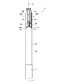
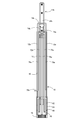
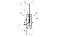
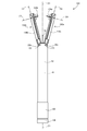
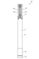
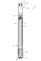
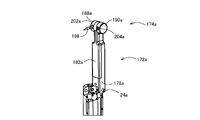
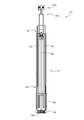
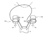
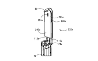
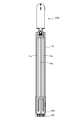
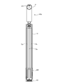
- the knot forming device 10 includes a cylindrical longitudinal base material 12 and a pair of first arm mechanism 14 a and second arm mechanism 14 b provided to be openable and closable at the distal end portion of the longitudinal base material 12.
- the base member of the longitudinal base material 12 is provided with an operation member 16 that can be rotated around the axis C1 of the longitudinal base material 12, and a rotational operation force of the operation member 16 provided in the longitudinal base material 12.
- An operating force transmission mechanism 18 is provided that transmits to the pair of first arm mechanism 14a and second arm mechanism 14b to operate the pair of first arm mechanism 14a and second arm mechanism 14b.
- the longitudinal base material 12 is comprised by the cylindrical shape by fixing a pair of partial cylindrical members 12a and 12b of a semicircular cross section in a combined state.
- the longitudinal base material 12 functions as a base portion
- the operation member 16 functions as an operation portion.
- the pair of first arm mechanism 14a and second arm mechanism 14b function as loop forming means as will be described later.
- the thread-like member L which functions as a to-be-ligated body is abbreviate
- a pair of support holes 22a and a shaft center line C2 are provided at a distal end portion of the longitudinal base material 12 at a predetermined interval on an axis C2 perpendicular to the opening and closing surfaces of the first arm mechanism 14a and the second arm mechanism 14b.
- a pair of support holes 22b are respectively formed on the axial center line C3 parallel to each other, and the first arm mechanism 14a is supported by the pair of support holes 22a so as to be rotatable around the axial center line C2, The second arm mechanism 14b is supported by the pair of support holes 22b so as to be rotatable around the axis C3.
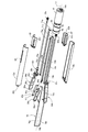
- the first arm mechanism 14a Since the pair of the first arm mechanism 14a and the second arm mechanism 14b are configured in the same manner, the first arm mechanism 14a will be described with reference to numeral symbols with a added to the end. About 14b, the same numerical code
- the first arm mechanism 14a has a pair of support holes 22a.
- a pair of projecting shafts 24a and an opening / closing connecting arm 26a are integrally provided, and supported by the pair of support holes 22 so as to be rotatable around an axis C2 passing through the centers of the pair of support holes 22.
- the first arm mechanism 14a is connected to an arm base 30a in which a through hole 28a penetrating in a direction orthogonal to the axial center line C2 is formed and to a universal joint 32a fitted in the through hole 28a. And a shaft 34a.
- the first arm mechanism 14a includes an arm main body 36a, a guide cover 38a, a lock plate 40a, a T-shaped bar support portion 42a, and a long lock operation bar 46a.
- the arm body 36a is provided on the arm base 30a so as to rotate about the axis C2 and to rotate about the rotation axis C4 of the through hole 28a together with the universal joint 32a.
- the guide cover 38a is fixed to the arm main body 36a so as to cover the entire facing surface on the second arm mechanism 14b side with a slight gap with respect to the facing surface.
- the lock plate 40a is accommodated so as to be movable in the longitudinal direction between the guide cover 38a and the opposing surface of the arm body 36a.
- the T-shaped bar support portion 42a is formed on the base end side of the guide cover 38a so as to be smaller than the width direction dimension of the arm body 36a and offset toward the second arm mechanism 14b.
- the lock operation bar 46a has a longitudinal dimension similar to the dimension in the width direction of the arm main body 36a. With the bar support part 42a exposed at both ends in the longitudinal direction, the lock support bar 46a is centered in the longitudinal direction inside the bar support part 42a. The portion is rotatably supported, and one end portion is engaged with the engagement recess 44a of the lock plate 40a.
- the lock operation bar 46a has a projection (not shown) at one end thereof, and the lock plate 40a with which the projection engages with the engagement recess 44a is at the distal end side position of the first arm mechanism 14a or the proximal end side. It is positioned in an inclined posture that reflects whether it is in position. For example, as shown in FIG. 6, when the lock plate 40a is located at the proximal end side position of the first arm mechanism 14a, one end side of the lock operation bar 46a is located at the proximal end side and the other end side is located at the distal end side. It is assumed to be an inclined posture. On the other hand, as shown in FIG.
- the T-shaped bar support portion 42a has a stopper function that allows both end portions of the lock operation bar 46a to abut against each other, whereby the lock plate 40a is positioned at the front end side position of the first arm mechanism 14a. And a proximal end position.
- FIGS. 2 and 5 show a state in which the first arm mechanism 14a is closed
- FIG. 5 shows a pair of needles 50 and 51.
- 7 shows a state in which the needle 50 on the distal end side is released and the needle 51 on the proximal end side is locked
- FIG. 7 shows that the needle 50 on the distal end side is locked and the needle 51 on the proximal end side is released.
- annular engagement grooves 52 and 53 are formed at both ends, respectively, and a through hole 54 through which the thread-like member L functioning as a ligature is passed is formed at the center in the longitudinal direction. Has been.
- the thread-like member L is fixed to the needles 50 and 51 by so-called caulking, which is deformed by applying an external force so that the through-hole 54 is crushed while the thread-like member L is passed through the through-hole 54.
- the thread-like member L may be fixed by forming a knot larger than the through hole 54 or by adhering the thread-like member to the needles 50 and 51.
- both ends of the needle 50 are formed in a tapered shape and both ends of the needle 51 are formed flat, but the needles 50 and 51 may have the same shape.
- FIG. 8 showing an enlarged view of the arm body 36a in the exploded perspective view of FIG. 3, the position of the tip of the arm body 36a and the arm at a predetermined distance from the tip of the opposing surface of the arm body 36a.
- a pair of receiving holes 56a for receiving one ends of the needles 50 and 51 are formed at two positions separated from the base 30a side, and at positions corresponding to the pair of receiving holes 56a of the guide cover 38a, A pair of through holes 58a through which the needles 50 and 51 can pass are formed.
- a pair of engagement holes 57a and 59a are formed at positions on the lock plate 40a corresponding to one and the other of the pair of receiving holes 56a and the pair of through holes 58a, respectively.
- the engagement hole 57a on the distal end side of the pair of engagement holes 57a, 59a engages with the engagement groove 52 of the needle 50 to lock the needle 50 when the lock plate 40a is at the distal end side position.
- the hole 50 is allowed to pass through. That is, a front rear circle in which a circle having a diameter larger than the diameter of the needle 50 and a rectangular notch having a width dimension larger than the groove bottom diameter of the engagement groove 52 of the needle 50 and smaller than the diameter of the needle 50 are connected. It is made into a shape.
- the engagement hole 59a on the base end side of the pair of engagement holes 57a, 59a is engaged with the engagement groove 52 of the needle 50 when the lock plate 40a is in the base end side position.
- the hole shape is formed to allow the needle 51 to pass therethrough.
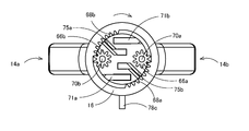
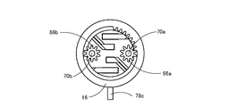
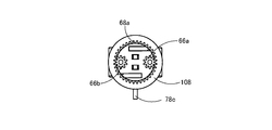
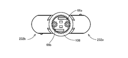
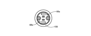
- the operation member 16 has a cylindrical shape, and on its inner peripheral surface, an arm opening / closing cam groove 60 for opening and closing the first arm mechanism 14a and the second arm mechanism 14b, and locks of the needle 50 and the needle 51 described later are provided.
- a needle lock cam groove 62 for operating the release is provided with a cylindrical groove cam 64 formed in an annular shape.
- the cylindrical groove cam 64 is formed integrally with the operation member 16, but is shown separately in FIG. 3 for the sake of illustration.
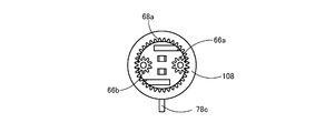
- inner peripheral teeth 68a and 68b are formed on the inner peripheral surface of the operation member 16 so that the pinions 66a and 66b for rotating the arm bodies 36a and 36b are engaged with each other. .
- the operating force transmission mechanism 18 transmits a rotational operating force for rotating the arm body 36a.
- the pinion 66a and the universal joint 32a are fixed to both ends, and the pinion 66b and the universal joint 32b for transmitting the operating force for rotating the arm body 36b are fixed to both ends.
- a second rotational operation force transmission shaft 70b is provided.
- the rotation axis C4 which is the longitudinal direction, is rotated relative to the arm base 30a clockwise, and at the same time, the arm body 36b is rotated by the clockwise rotation operation force transmitted via the second rotation operation transmission shaft 70b.
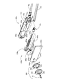
- the operating force transmission mechanism 18 includes a first opening / closing operation force transmission link 72a and a second opening / closing operation force transmission link 72b.
- the first opening / closing operation force transmission link 72a is pivotally connected to the opening / closing connection arm 26a in order to transmit an opening / closing operation force for opening / closing the first arm mechanism 14a between the open position and the closed position.
- the base end portion has a cam engaging portion 71a that protrudes at right angles to the direction and engages with the arm opening / closing cam groove 60.
- the second opening / closing operation force transmission link 72b is pivotally connected to the opening / closing connection arm 26b to transmit the opening / closing operation force for opening / closing the second arm mechanism 14b between the open position and the closed position.
- the base end portion has a cam engaging portion 71b that protrudes at right angles to the direction and engages with the arm opening / closing cam groove 60.
- FIG. 4 shows a state in which the first arm mechanism 14a is rotated to the open position.
- the first arm mechanism 14a is rotated to the open position by the movement of the first opening / closing operation force transmission link 72a.
- the first opening / closing operation force transmission link 72 a moves in accordance with the operation of the operation member 16. Specifically, when the operation member 16 is operated, the arm opening / closing cam groove 60 is rotated. When the arm opening / closing cam groove 60 rotates and the first opening / closing operation force transmission link 72a passes through a section in which the cam curve of the arm opening / closing cam groove 60 changes toward the distal end side of the longitudinal base material 12, the first opening / closing operation force is transmitted. The transmission link 72 a is moved to the distal end side of the longitudinal base material 12.
- FIG. 5 shows a state in which the first arm mechanism 14a is rotated to the open position.
- the first arm mechanism 14a is rotated to the closed position by the movement of the first opening / closing operation force transmission link 72a.
- the first opening / closing operation force transmission link 72 a moves in accordance with the operation of the operation member 16. Specifically, when the operation member 16 is operated, the arm opening / closing cam groove 60 is rotated.
- the second opening / closing operation force transmission link 72b of the second arm mechanism 14b is related to the operation of the operation member 16, and the first opening / closing operation force transmission link 72b.
- the longitudinal base 12 is moved to the distal end side and the longitudinal base 12 to the proximal end side.
- the pair of first arm mechanism 14a and second arm mechanism 14b are opened and closed.
- the operating force transmission mechanism 18 receives the one of the needles 50 and 51 between the first arm mechanism 14a and the second arm mechanism 14b and passes the other to the first arm mechanism 14a and the second arm mechanism 14b.
- a first push rod 76a and a second push rod 76b are provided to switch the pair of needles 50 and 51 from one of the engaged state and the released state to the other when they are in the closed state.
- the first push rod 76a has a T-shaped push-up portion 74a at the distal end that abuts against one end of the pair of lock operation bars 46a and 46b and rotates them, and protrudes at right angles to the longitudinal direction.
- the base end portion has a cam engagement portion 75a that engages with the lock cam groove 62.
- the second push rod 76b has a T-shaped push-up portion 74b that abuts against the other ends of the pair of lock operation bars 46a and 46b to rotate them, and protrudes at a right angle to the longitudinal direction.
- the base end portion has a cam engaging portion 75 b that engages with the needle lock cam groove 62.
- the other of the needle lock cam grooves 62 is the longitudinal base 12.
- the cam curve is formed so as to be drawn toward the base end side.
- FIG. 6 shows a state where the needle 50 is released by the lock plate 40a and the needle 51 is engaged by the lock plate 40a in the first arm mechanism 14a.
- the needle 50 is engaged by the lock plate 40b and the needle 51 is released by the lock plate 40b.
- FIG. 7 shows a state where the needle 50 is engaged by the lock plate 40a and the needle 51 is opened by the lock plate 40a in the first arm mechanism 14a.
- the needle 50 is opened by the lock plate 40b and the needle 51 is engaged by the lock plate 40b.
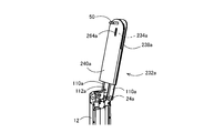
- the first arm mechanism 14a and the second arm mechanism 14b are in a state where the proximal end needle 51 is held by the first arm mechanism 14a and the distal end needle 50 is held by the second arm mechanism 14b. Closed.
- one end of the needle 50 on the distal end side is released from the engaged state by the lock plate 40b of the second arm mechanism 14b, and at the same time, the other end of the needle 50 is locked by the first arm mechanism 14a.
- the plate 40a is brought into the engaged state from the released state.
- one end of the proximal needle 51 is brought into the engaged state from the released state by the lock plate 40a of the first arm mechanism 14a, and at the same time from the released state to the engaged state by the lock plate 40b of the second arm mechanism 14b.
- the proximal needle 51 is held by the second arm mechanism 14b and the distal needle 50 is held by the first arm mechanism 14a. It becomes a state. That is, the distal side needle 50 and the proximal side 51 are exchanged between the first arm mechanism 14a and the second arm mechanism 14b.
- the engagement hole in the distal end side of the receiving hole 56a of the arm body 36a, the one on the distal end side in the through hole 58a of the guide cover 38a, and the engagement hole in the lock plate 40a of the first arm mechanism 14a It functions as a first holding member that holds the needle 50 on the distal end side in combination with the portion where 57a is formed.
- the front end side of the receiving hole 56b of the arm body 36b, the front end side of the through hole 58b of the guide cover 38b, and the engagement hole 57b of the lock plate 40b of the second arm mechanism 14b are provided.
- the formed portion is combined to function as a second holding member that holds the needle 50 on the distal end side.
- the base end side of the receiving hole 56a of the arm body 36a, the base end side of the through hole 58a of the guide cover 38a, and the engagement hole of the lock plate 40a of the first arm mechanism 14a functions as a third holding member that holds the needle 51 on the proximal end side in combination with the portion where 59a is formed.
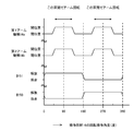
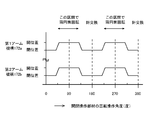
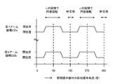
- FIG. 13 shows a lock and release operation of the needle 50 and the needle 51 by the lock plate 40a and the lock plate 40b by one rotation operation of the operation member 16 (however, the lock and release operation by the lock plate 40b is shown in FIG. Is not the same as the operation of the lock plate 40a), the rotation of the arm body 36a of the first arm mechanism 14a and the arm body 36b of the second arm mechanism 14b, and the first arm mechanism 14a and second arm mechanism 14b.
- the horizontal axis of the chart of FIG. 13 indicates an angle obtained by rotating the operation member 16 clockwise as viewed from the directions of FIGS.
- 11 and 12. 11 is about 135 degrees from the origin of the horizontal axis of the chart, and FIG. 12 is a position rotated about 45 degrees, that is, 270 degrees from FIG.
- the one rotation operation of the operation member 16 may be a manual operation or a remote operation in which the operation member 16 is rotated by a motor.
- the moving member 78 has a cylindrical longitudinal base. It is accommodated in the longitudinal base material 12 so that it can project from the front-end
- the moving member 78 is a part that is bent in an inverted U shape as a whole from one wire, and includes a short wire portion 78b that connects the ends of a pair of long wire portions 78a parallel to each other, and one long wire portion 78a. And an operation projection 78c protruding outward from the long hole 80 formed in the partial cylindrical member 12a.
- the to-be-ligated body L is moved in the direction away from the longitudinal base material 12 along the longitudinal direction of the first arm mechanism 14a and the second arm mechanism 14b by the short line portion 78b of the moving member 78 that has been pushed out.
- the projecting operation of the moving member 78 may be manually operated on the operation projection 78c, or may be a remote operation operated using an actuator such as a pneumatic cylinder or an electric cylinder.
- a cylindrical receiving member 82 is disposed on the base end side in the longitudinal base 12.
- the receiving member 82 rotatably supports the first rotational operation force transmission shaft 70a and the second rotational operation force transmission shaft 70b. Further, the receiving member 82 supports the first opening / closing operation force transmission link 72a and the second opening / closing operation force transmission link 72b so as to be movable in the longitudinal direction, and the first opening / closing operation force transmission link 72a and the second opening / closing operation force.
- the cam engaging portion 71a and the cam engaging portion 71b provided on the base end side of the transmission link 72b are guided in the longitudinal direction using the pair of guide holes 82a.
- the receiving member 82 supports the first push rod 76a and the second push rod 76b so as to be movable in the longitudinal direction, and is provided on the base end side of the first push rod 76a and the second push rod 76b.
- the engaging portion 75a and the cam engaging portion 75b are guided in the longitudinal direction using the pair of guide holes 82b.
- the operation member 16 when the operation member 16 is rotated, as shown in FIG. 13, the first arm mechanism 14a and the second arm mechanism 14b are opened and closed, and the needle 50 and the needle 51 are locked. The release operation and the rotation operation of the arm main body 36a and the arm main body 36b are performed. Thereafter, when the thread member L is removed from the first arm mechanism 14a and the second arm mechanism 14b by the moving member 78, a loop of the thread member L in which the knot M1 is formed is automatically formed.
- the operation of the knot forming apparatus 10 of this embodiment will be specifically described below.
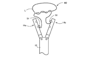
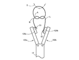
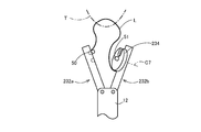
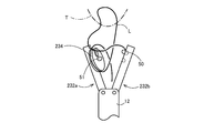
- the thread-like member L In order for the knot formed by the thread-like member L to be a knot that closes the thread-like member L surrounding the ligation symmetrical object in an annular shape, the thread-like member L, the first arm mechanism 14a, the second arm mechanism 14b, the longitudinal base The ligation symmetry object is surrounded in a closed path made of the material 12.
- An annular path combining the thread-like member L and the broken line D in FIG. 14 is a closed path referred to here.
- the first arm mechanism 14a and the second arm mechanism are moved from the state in which the distal end needle 50 is locked by the lock plate 40b of the second arm mechanism 14b.
- the suture portion of the living tissue T sandwiched between the distal end portion of the first arm mechanism 14a and the distal end portion of the second arm mechanism 14b is penetrated by the needle 50 on the distal end side, and the first arm mechanism 14a If the first arm mechanism 14a and the second arm mechanism 14b are opened while the distal end side needle 50 is locked by the lock plate 40a, a part of the living tissue T becomes the thread-like member L, the first arm mechanism 14a, and the second arm mechanism 14b.
- the arm mechanism 14b and the longitudinal base 12 are surrounded by a closed path.
- the operation member 16 is at an operation position near 45 degrees.
- FIG. 14 schematically shows this state.
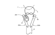
- the arm main body 36a of the first arm mechanism 14a and the arm main body 36b of the second arm mechanism 14b are connected to each other by the first arm mechanism 14a and the second arm mechanism 14b.
- a loop is formed around the arm body 36b by being rotated once in the same rotational direction around the rotation axes C4 and C5 in the longitudinal direction of the first arm mechanism 14a and the second arm mechanism 14b in parallel with the opening / closing surface.
- the loop here refers to a surrounding portion when the thread-like member L surrounds a certain axis over one round and 360 degrees or more.
- the mapping of the thread-like member L self-intersects, and the axis exists in an annularly closed portion including the intersection of the mapping.
- the real part that is the origin of the annular part of the map is the loop.
- “passing” means that the loop and the end of the yarn pass relative to each other along the axis that defines the loop, and the relative positional relationship in the axial direction is switched. Since the loop is defined in relation to the axis of the loop, for example, in FIG.
- the loop of the thread-like member that appears to be a simple S shape in the front view is the direction of the rotation axis C5 as shown in FIG.
- a closed ring may occur, but if the above "pass” is made in the direction along the axis, the knot can be made to see how it looks from the other direction, and conversely the axis If the above-mentioned “passing” is not performed in the direction along the line, a knot cannot be formed even if it looks like a loop is seen from the other direction.
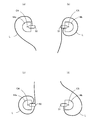
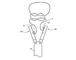
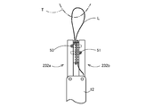
- the schematic diagrams of FIGS. 15, 16 and 17 show a state after a loop in the above sense is formed by the first loop forming operation.
- FIGS. 16 (a) and 16 (b) show a state in which the living tissue T is positioned in front of the figure with respect to the knot forming device 10
- FIGS. 16 (c) and 16 (d) show the living tissue T in the knot. It is the figure seen from the base end side in the direction of rotation-axis C4, C5, respectively, when it is located in the back
- a loop is formed around the arm body 36a. Due to the overall symmetry, knots are formed in the same way in the following description.
- a loop is formed around at least one of the arm bodies 36a and 36b by rotating both arm bodies 36a and 36b in the same direction.
- the loops shown in FIGS. 16B and 16D can be formed simultaneously. Subsequently, the first arm mechanism 14a and the second arm mechanism 14b are closed by a first arm approaching operation that operates the operating member 16 to around 135 degrees.
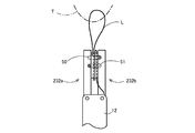
- FIG. 17 shows a state where the first arm approaching operation is completed.
- FIG. 17 shows a state before the first switching operation
- FIG. 18 shows a state after the first switching operation. 17 and 18, the state in which the needle 50 and the needle 51 are locked is indicated by hatching in the first arm mechanism 14a and the second arm mechanism 14b.
- the operation member 16 When the operation member 16 is operated to around 225 degrees, the first arm mechanism 14a and the second arm mechanism 14b are opened. 19 and 20 show the first arm separation operation.
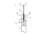
- the thread-like member L is wound around the second arm mechanism 14b so as to form a loop R composed of the thread-like member L, and the first needle 50 and the proximal-side needle 51 of the distal end side are formed.
- the delivery between the arm mechanism 14a and the second arm mechanism 14b is completed.
- the closed path composed of the thread-like member L, the first arm mechanism 14a, the second arm mechanism 14b, and the longitudinal base material 12 is already knotted in a topological sense at this point.
- the shape before and after the deformation is said to be topologically the same.
- a discontinuous deformation such as a deformation in which the thread passes through the thread, or a deformation in which the ring is cut once and the thread is traversed and then closed again.
- Leidhoff movement the shape that can be deformed only by continuous deformation (referred to as Leidhoff movement) without topology is the same topologically.
- the topology is different between an annularly closed thread not including a knot and a closed thread including a knot.
- the knot already in topology means that the closed path composed of the thread-like member L, the first arm mechanism 14a, the second arm mechanism 14b, and the longitudinal base material 12 can be closed only by continuous deformation. This means that it can be deformed into a shape in which a knot shape exists only in the portion consisting of L.
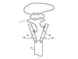
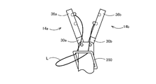
- FIG. 21 shows a state in which the thread-like member L is detached from at least the first arm mechanism 14a of the first arm mechanism 14a and the second arm mechanism 14b after the first arm separation operation.
- the thread-like member L is disengaged from the first arm mechanism 14a and the second arm mechanism 14b when a first arm separation operation or a series of operations including a first arm separation operation and an operation of projecting the moving member 78 in the arrow direction is performed.
- the thread-like member L when the first arm separation operation and the operation of projecting the moving member 78 in the direction of the arrow are performed in the schematic diagram of FIG. 21 by continuous deformation while maintaining the same topology topology of the closed path.
- a so-called single knot knot M1 is formed only by the thread-like member L.
- the thread-like member L may be removed from at least the second arm mechanism 14b by moving the longitudinal base 12. If there is no hindrance in subsequent operations performed by the first arm mechanism 14a and the second arm mechanism 14b, the thread-like member L does not necessarily have to be removed from the first arm mechanism 14a.
- the thread-like member L is tightened to obtain the single ligature M1 shown in FIG. That is, the single ligature M1 by the thread-like member L is automatically formed by such a single ligature formation operation.
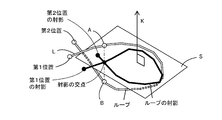
- the entity of the thread-like member L projected as the intersection of the closed paths is , A three-dimensional intersection composed of two positions of the thread-like member L, that is, a first intersection position A closer to the first position that is one end of the thread-like member L and a second intersection position B farther away. Passing the first position, which is one end portion of the thread-like member L through which the loop passes, in the direction from the second intersection position B side to the first intersection position A side, that is, in the direction of the arrow of the virtual axis K. Can make a knot. For example, referring to FIG.
- the thread-like member L is transferred by the delivery of the needle 50 and the needle 51 following the closing operation of the first arm mechanism 14a and the second arm mechanism 14b in a state where a loop is formed around the arm body 36b.
- the portion that is passed through the needle 50 that is the first position of the first position is the second of the two positions of the thread-like member L corresponding to the intersection of the loops, the second position closer to the second intersection position B that is farther from the first position. Since the loop is relatively passed to the one intersection position A side, a knot M1 is formed in the loop.
- the operation member 16 when the operation member 16 is operated up to around 135 degrees, the arm main body 36a of the first arm mechanism 14a and the arm main body 36b of the second arm mechanism 14b are rotated around the longitudinal axis thereof. It is also possible to use the operation member 16 having the inner peripheral teeth 68a and 68b having the number of teeth for performing the operation of rotating twice. Or if it is the structure which rotates the arm main body 36a and the arm main body 36b using the 2nd operation member independent of the operation member 16 used for opening and closing of the 1st arm mechanism 14a and the 2nd arm mechanism 14b. The second operating member can be rotated by an angle twice as large as when the arm main body 36a and the arm main body 36b are rotated once.
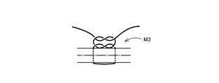
- the thread-like member L is wound twice around the second arm mechanism 14b to form a loop.
- the needle 50 and the needle 51 are delivered from this state and the moving member 78 is pushed out to remove the thread-like member L from the first arm mechanism 14a and the second arm mechanism 14b, as shown in the schematic diagram of FIG. A loop in which a so-called double knot knot M2 is formed is formed.
- the double ligation M2 of FIG. 25 is obtained by tightening the thread-like member L. That is, according to the knot forming apparatus 10 of the present embodiment, the double ligation M2 is automatically formed by such a double ligation forming operation.
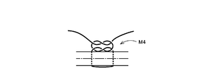
- the arm main body 36a and the arm when the second single ligature is formed with respect to the rotation direction of the arm main body 36a and the arm main body 36b when the first single ligature is formed.
- a loop in which the so-called male knot M4 shown in the schematic diagram of FIG. 28 is formed is formed, and the thread-like member L is tightened to obtain the male knot M4 of FIG. It is done. That is, according to the knot forming apparatus 10 of the present embodiment, the male knot M4 is automatically formed by performing the single knot forming operation twice.
- the arm main body 36a and the arm main body 36b can be rotated in the reverse direction by reversing the rotation direction of the operation member 16.
- the single ligation M1 is formed by performing the single ligation formation operation subsequently, so that the second ligation M2 is formed in the first stage as shown in FIG.
- a surgical ligature M5 having a single ligature M1 in the second stage is formed.
- Such a surgical ligature M5 can also be automatically formed by using the knot forming device 10 of the present embodiment.
- the second arm mechanism 14 b holds the needle 50
- the first arm mechanism 14 a holds the needle 51. Therefore, the second knot can be formed by performing the replacement operation of the needles 50 and 51 again, returning the apparatus to the initial state, and performing the same operation.
- the first arm mechanism 14a is formed. Since the second arm mechanism 14b is configured to be functionally symmetrical, the second-stage knot can be formed immediately after the first-stage knot has been formed. In this case, the first arm mechanism 14a, the second arm mechanism 14b, and these components are used in reverse to the procedure for forming the first knot. In the above description of the present specification, the subscripts a and b may be replaced.
- the arm main body 36a of the first arm mechanism 14a and the arm main body 36b of the second arm mechanism 14b are rotated around the longitudinal axis in the same rotational direction.
- the arm main body 36b of the second arm mechanism 14b to which the proximal end needle 51 is fixed may be rotated once.
- the first arm mechanism 14 a and the second arm mechanism 14 b are operated by operating the operation member (operation unit) 16 provided at the base end portion of the longitudinal base material (base portion) 12.
- the operation member (operation unit) 16 provided at the base end portion of the longitudinal base material (base portion) 12.
- the first crossing position of the thread-like member L passed through the needle 50 and the second crossing position of the thread-like member L passed through the needle 51 are separated from each other.
- both ends of the thread-like member L are held at positions apart from the separate first arm mechanism 14a and second arm mechanism 14b, so that the thread-like member L is not easily entangled and tightened thereafter. And cutting becomes easy.
- the arm main bodies (operation units) 36a and 36b are provided in the first arm mechanism 14a and the second arm mechanism 14b, and the operation member (operation unit) 16 is 1 Following the first knot forming operation, the first arm mechanism 14a and the second arm mechanism 14b are separated from each other, and the first position and the second position of the thread-like member L are held by the second holding member and the third holding member.
- a second loop forming operation for forming a loop of the thread-like member L by the arm main bodies (operation units) 36a and 36b, an arm approaching operation for causing the first arm mechanism 14a and the second arm mechanism 14b to approach each other, A second state in which the first position and the second position of the thread-like member L are switched from the state of being held by the second holding member and the third holding member to the state of being held by the first holding member and the fourth holding member.
- the second arm that separates the first arm mechanism 14a and the second arm mechanism 14b from each other in a state in which the first position and the second position of the thread-like member L are held by the first holding member and the fourth holding member.
- the loop is again passed to the first position by sequentially performing the separation operation.
- the arm main bodies (loop forming means) 36a and 36b are provided in both the first arm mechanism 14a and the second arm mechanism 14b, the first arm mechanism 14a and the second arm mechanism 14b are functionally symmetrical.
- the first loop forming operation By sequentially executing the first loop forming operation, the arm approaching operation, the first switching operation, and the first arm separating operation, the second loop forming operation, the loop can be passed again to the first position of the thread-like member L to form the next second knot.
- Multi-stage knots can be formed automatically with a simple operation.
- the thread-like member L can be wound around the first arm mechanism 14a and the second arm mechanism 14b itself at the time of loop formation, a knot forming apparatus that is space efficient and compact and can be automatically ligated is provided. can get.
- both ends of the thread-like member L are held separately by the first arm mechanism and the second arm mechanism before and after the knot formation, so that the thread-like member L is not easily entangled, and subsequent tightening and cutting are easy. .
- first arm mechanism 14a and the second arm mechanism 14b at the tip of the knot forming device 10 are opened and closed, a symmetrical object sandwiched between the first arm mechanism 14a and the second arm mechanism 14b, for example, the living tissue T Knots can be formed around. Further, the first arm mechanism 14a and the second arm mechanism 14b can be operated in the first position and the second position even after the loop forming operation by the rotation of the second arm main body 36b as the second holder in accordance with the operation of the operation member 16. Can be exchanged with.
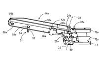
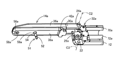
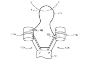
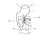
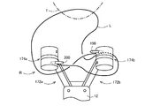
- FIG. 32 is a front view showing a state in which the first arm mechanism 102a and the second arm mechanism 102b of the knot forming apparatus 100 according to another embodiment of the present invention are open
- FIG. 33 is a first view of the knot forming apparatus 100
- 34 is a front view showing a state in which the arm mechanism 102a and the second arm mechanism 102b are closed
- FIG. 34 is an exploded perspective view showing the knot forming device 100.
- the knot forming apparatus 100 functions as an operating unit based on the rotational operation force transmitted through the first rotational operation force transmission shaft 70a and the second rotational operation force transmission shaft 70b, and the needles 50 and 51.
- a pair of first cylindrical rotating mechanism 104a and second cylindrical rotating mechanism 104b functioning as a needle locking mechanism that detachably holds the first and second cylindrical rotating mechanisms 104a and 102b are provided at the distal ends of the first arm mechanism 102a and the second arm mechanism 102b, respectively.
- the operating force transmission mechanism 18 does not include the first push rod 76a and the second push rod 76b, and a pair of opening / closing operation members that are provided at the base end portion of the longitudinal base 12 so as to be rotatable as operation members.
- 106 and the rotation operation member 108 are different from the knot forming apparatus 10 in FIG. To have.
- the knot forming apparatus 100 includes a cylindrical long base 12, a pair of first arm mechanism 102 a and second arm mechanism 102 b, a pair of opening / closing operation members 106, a rotation operation member 108, and an operation force transmission mechanism 18.
- the pair of first arm mechanism 102a and second arm mechanism 102b are rotatably supported around the axial center line C2 and the axial center line C3 that are parallel to each other at the distal end portion of the longitudinal base material 12, and are provided to be openable and closable. ing.
- the pair of opening / closing operation members 106 and the rotation operation member 108 are provided so as to be rotatable around the axis C1 of the longitudinal base material 12 at the proximal end portion of the longitudinal base material 12, and are provided so as to be relatively rotatable with respect to each other. Yes.
- the operating force transmission mechanism 18 is provided in the longitudinal base material 12, and the opening / closing operation force of the opening / closing operation member 106 and the rotation operation member 108 are used as a pair of first arm mechanism 102 a and second arm mechanism 102 b, and a pair of first cylindrical rotations. This is transmitted to the mechanism 104a and the second rotation mechanism 104b.
- the pair of opening / closing operation members 106 and the rotation operation member 108 function as an operation unit.
- the first arm mechanism 102a includes an arm main body 114a, a cover 118a, a first cylindrical rotation mechanism 104a, and a rotation drive shaft 122a.
- the arm main body 114a is positioned between a pair of parallel plates 110a each having a projecting shaft 24a with the open / close connecting arm 26a fixed to one side and projecting outward, and the universal joint 32a is rotatable.
- a joint receiving member 112a formed with a through hole 28a to be received in the base end portion.
- the arm main body 114a and the cover 118a have a circular opening 116a formed at the tip, and are fixed to the arm main body 114a so as to cover the opposing surface of the arm main body 114a.
- the rotation drive shaft 122a is supported between the arm main body 114a and the cover 118a so as to be rotatable about a central axis of the through hole 28a, that is, a rotation axis C4 parallel to the longitudinal direction of the first arm mechanism 102a, and universally connected to the base end.
- the joint 32a is connected, and the pinion 120a is fixed to the tip.
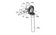
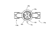
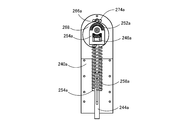
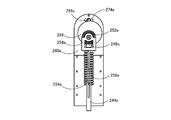
- FIG. 37 is a longitudinal sectional view illustrating the configuration of the first cylindrical rotating mechanism 104a.
- the first cylindrical rotation mechanism 104a includes a cylindrical member 128a, a bevel gear member 132a, and a guide plate 136a.
- the cylindrical member 128a has a central shaft portion 126a fitted into a cylindrical bearing 124a projecting inwardly from the arm main body 114a, and the first arm mechanism 102a and the second arm mechanism 102b by the cylindrical bearing 124a.
- the bevel gear member 132a is rotatably supported by the outer peripheral surface of the tip end portion of the cylindrical bearing 124a and has a plate-like lock flange 130a protruding to the outer periphery.
- the guide plate 136a includes a guide plate 136a that is sandwiched between the arm main body 114a and the cover 118a and that forms an annular slot 134a between the outer peripheral edge of the lock flange 130a located on the inner side.
- the bevel gear member 132a meshes with the pinion 120a provided at the shaft end of the rotation drive shaft 122a, so that the cylindrical member 128a and the bevel gear member 132a are rotationally driven around the rotation axis C6.
- the cylindrical member 128a is urged in the protruding direction by a spring 138a inserted between the cylindrical member 128a and the bevel gear member 132a.
- a spring 138a inserted between the cylindrical member 128a and the bevel gear member 132a.
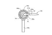
- FIG. 39 and 40 are views seen from the side of the arm main body 114a showing the state in which the needle 50 is released and the needle 51 is locked between the lock flange 130a and the guide plate 136a.
- FIG. 40 is a view of the cylindrical rotation mechanism 104a as viewed from the arm main body 114a side
- FIG. 40 is a view showing the cylindrical member 128a, the rotation drive shaft 122a, and the cover 118a from FIG. 41
- FIG. 41 is a view corresponding to FIG. 40 showing a state in which the needle 50 is locked and the needle 51 is released between the lock flange 130a and the guide plate 136a.
- FIG. 42 is a view corresponding to FIG. 39 showing a state in which the cylindrical member 128a is rotated in a state where the needle 50 is released and the needle 51 is locked between the lock flange 130a and the guide plate 136a.
- the radial dimension of the annular slot 134a formed between the outer peripheral edge of the lock flange 130a and the inner peripheral edge of the guide plate 136a is smaller than the outer diameter of the needle 50 and the needle 51, and is smaller than the groove bottom diameter of the engagement groove 52. Is also set larger. Further, at two positions on the straight line passing through the rotation axis C6 and orthogonal to the rotation axis C4 in the inner peripheral edge of the guide plate 136a, an arc shape having a curvature radius larger than the curvature radius of the outer diameter of the needle 50 and the needle 51 is formed.
- the outer arc-shaped notches 139a and 140a having the outer arc are formed at positions opposite to the rotation axis C6.
- the two outer circumferential edges of the lock flange 130a are 180 degrees apart in the circumferential direction and have a radius of curvature larger than the radius of curvature of the needles 50 and 51, and the outer arc-shaped notches 139a and 140a.
- the inner arc-shaped notches 142a and 144a that allow the needle 50 and the needle 51 to pass between the guide plate 136a and the inner peripheral edge of the guide plate 136a are smaller than the groove bottom diameter of the engagement groove 52 of the needle 50 and the needle 51.
- Inner rectangular cutouts 146a and 148a that are larger and have an interval smaller than the outer diameter of the needle 50 are formed to be connected in a semi-front and rear circular shape.
- needle receiving grooves 150a and 152a having a semicircular cross section parallel to the rotation axis C6 for receiving the needle 50 and the needle 51 are provided. Is formed.
- the needle 50 received in the needle receiving groove 150a of the cylindrical member 128a is allowed to be removed between the outer arcuate cutout 139a and the inner arcuate cutout 142a, and the cylindrical member 128a
- a state in which the needle 51 received in the needle receiving groove 152a is prevented from coming off between the outer arc-shaped notch 140a and the inner rectangular notch 148a is shown.
- the lock flange 130a and the bevel gear member 132a are rotated counterclockwise as shown in FIG. 40 from this state, the cylindrical member 128a is also rotated by being pushed by the needle 51 that is prevented from coming off, and the cylindrical member 128a.
- FIG. 41 shows this state.
- the needle 50 is allowed to slip out between the outer arcuate cutout 139a and the inner arcuate cutout 142a, and the needle 51 is removed from the outer arcuate cutout 140a and the inner rectangular cutout. Omission is prevented between the notch 148a. From this state, when the lock flange 130a and the bevel gear member 132a are rotated counterclockwise by a predetermined angle, as shown in FIG.
- the needle 50 is positioned between the outer arcuate cutout 139a and the inner rectangular cutout 146a. And the needle 51 is prevented from coming off between the outer arcuate cutout 140a and the inner arcuate cutout 144a. In other words, the locked state of the needle 50 and the needle 51 is switched depending on which direction is last rotated.
- a combination with the portion where the outer arc-shaped notch 139 a is formed functions as a first holding member that holds the needle 50.
- the combination with the portion where 139 b is formed functions as a second holding member that holds the needle 50.
- the combination with the portion where 140 a is formed functions as a third holding member that holds the needle 51.
- the combination with the portion where 140 b is formed functions as a fourth holding member that holds the needle 51.
- a cylindrical opening / closing operation member 106 provided at the proximal end portion of the longitudinal base material 12 of the knot forming device 100 of the present embodiment so as to be rotatable around its axis C1;
- a cylindrical rotation operation member 108 provided adjacent to the opening / closing operation member 106 so as to be rotatable around the axis C1 of the longitudinal base material 12 is provided so as to be operated independently of each other.
- the opening / closing member 106 is integrally provided with a cylindrical groove cam 64 in which an arm opening / closing cam groove 60 for opening / closing the first arm mechanism 102a and the second arm mechanism 102b is formed in an annular shape.
- the cylindrical groove cam 64 is formed integrally with the operation member 16, but is shown separately in FIG. 34 for convenience of illustration.
- FIGS. 45 shows a state in which the pair of first arm mechanism 102a and second arm mechanism 102b is opened
- FIG. 46 shows a state in which the first arm mechanism 102a and second arm mechanism 102b are closed.
- the operation force transmission mechanism 18 transmits a rotational operation force for rotating the first cylindrical rotation mechanism 104a. Therefore, the pinion 66a meshing with the inner peripheral teeth 68a of the rotation operation member 108 shown in FIG. 45 and the first rotation operation force transmission shaft 70a having the universal joint 32a fixed at both ends and the operation force for rotating the second rotation mechanism 104b are provided. 45, a pinion 66b meshing with the inner peripheral teeth 68a of the rotation operation member 108 shown in FIG. 45 and a second rotation operation force transmission shaft 70b fixed to both ends of the universal joint 32b are provided.
- the operating force transmission mechanism 18 is pivotally connected to the open / close connection arm 26a in order to transmit an opening / closing operation force for opening and closing the first arm mechanism 102a between the open position and the closed position.
- the first opening / closing operation force transmission link 72a having a cam engaging portion 71a protruding at a right angle with respect to the arm opening / closing cam groove 60 at the base end portion and the second arm mechanism 102b in the open position and the closed position
- a cam engaging portion 71b is connected to the opening / closing connecting arm 26b so as to be pivotable, protrudes at right angles to the longitudinal direction, and engages with the arm opening / closing cam groove 60.
- a second opening / closing operation force transmission link 72b at the base end.
- FIG. 47 shows the opening / closing operation of the first arm mechanism 102a and the second arm mechanism 102b by one rotation operation of the opening / closing operation member 106, and the first cylindrical rotation mechanism 104a and the second cylinder operation by the rotation operation member 108 in a predetermined rotation phase section. It is a chart explaining the state in which the rotation operation of the cylindrical rotation mechanism 104b and the replacement operation of the needle 50 and the needle 51 are executed in a predetermined order for knot formation.
- the horizontal axis of the chart in FIG. 47 indicates an angle obtained by rotating the opening / closing operation member 106 clockwise as viewed from the directions of FIGS. 45 and 46.
- the rotation operation member 108 When the rotation member 108 rotates the cylindrical member 128a of the first cylindrical rotation mechanism 104a and the cylindrical member 128b of the second cylindrical rotation mechanism 104b to wind the thread-like member L, the rotation operation member 108 and the first arm mechanism 102a
- the needle 50 and the needle 51 are exchanged between the first cylindrical rotating mechanism 104a and the second cylindrical rotating mechanism 104b by operating in the section where the two-arm mechanism 102b is in the open position, the first arm mechanism 102 and the first It is operated in a section where the two-arm mechanism 102b is in the closed position.
- 45 is about 135 degrees from the origin of the horizontal axis of the chart
- FIG. 46 is a position rotated about 45 degrees.
- the rotation operation of the opening / closing operation member 106 and the rotation operation member 108 may be a manual operation or a remote operation that is rotated by a motor.
- the first arm mechanism 102a and the second arm mechanism are moved from the state in which the needle 50 is locked by the second cylindrical rotation mechanism 104b of the second arm mechanism 102b. 102b is closed.
- the suture portion of the living tissue T sandwiched between the distal end portion of the first arm mechanism 102a and the distal end portion of the second arm mechanism 102b is penetrated by the needle 50.
- the rotation operation member 108 is operated, whereby the cylinder member 128a of the first cylinder rotation mechanism 104a and the cylinder member 128b of the second cylinder rotation mechanism 104b Is a rotation axis C4 parallel to the opening and closing surfaces of the first arm mechanism 102a and the second arm mechanism 102b and parallel to the longitudinal direction of the first arm mechanism 102a.
- the first arm mechanism 102a is parallel to the longitudinal direction of the second arm mechanism 102b.
- a half rotation, that is, a relative rotation is made about rotation axes C6 and C7 orthogonal to the axes C4 and C5.
- the schematic diagram of FIG. 49 shows a state in which this loop formation operation is performed.
- the rotation operation member 108 includes a first rotation operation member having an inner peripheral tooth with which the pinion 66a of the first rotation operation force transmission shaft 70a that rotates and drives the first cylinder rotation mechanism 104a, and a second cylinder rotation mechanism.
- the second rotational operation force transmission shaft 70b for rotating and driving the 104b can be divided and provided with a second rotational operation member having an inner peripheral tooth with which the pinion 66b meshes.
- the first cylindrical rotation mechanism 104a and the second cylindrical rotation mechanism 104b can be independently rotated by the first rotation operation member and the second rotation operation member.
- One of the cylindrical member 128a of 104a and the cylindrical member 128b of the second cylindrical rotating mechanism 104b is rotated to make one relative rotation, and the cylindrical member 128a of the first cylindrical rotating mechanism 104a and the cylinder of the second cylindrical rotating mechanism 104b.
- the thread-like member L may be wound around one outer peripheral surface of the member 128b. Further, as described above, when one of the cylindrical member 128a of the first cylindrical rotating mechanism 104a and the cylindrical member 128b of the second cylindrical rotating mechanism 104b is rotated, the other cylindrical rotating mechanism may be removed.
- the first arm mechanism 102a and the second arm mechanism 102b are closed by a first arm approach operation that operates the opening / closing operation member 106 to around 135 degrees.
- the schematic diagram of FIG. 50 shows the first arm approaching operation.
- one end of the needle 50 is moved to the first cylindrical rotation mechanism 104a by a first switching operation for returning the rotation operation member 108 by a predetermined angle.
- the other end of the needle 50 is locked by the lock flange 130b of the second cylindrical rotating mechanism 104b.
- FIG. 50 shows a state before the first switching operation
- FIG. 51 shows a state after the first switching operation. 50 and 51, the state in which the needle 50 and the needle 51 are locked is indicated by oblique lines in the cylindrical member 128a of the first cylindrical rotating mechanism 104a and the cylindrical member 128b of the second cylindrical rotating mechanism 104b.
- FIG. 52 shows a state after the separation operation between the first arm mechanism 102a and the second arm mechanism 102b.
- the thread-like member L is wound around the second arm mechanism 102b to form a loop R, and the cylindrical member 128a of the first cylindrical rotating mechanism 104a and the cylindrical member 128b of the second cylindrical rotating mechanism 104b
- the delivery of the needle 50 and the needle 51 is completed.
- FIG. 52 as in FIG.
- the closed path composed of the thread-like member L, the first arm mechanism 102a, the second arm mechanism 102b, and the longitudinal base 12 is already knotted in a topological sense at this point. It has become.
- the closed path composed of the thread-like member L, the first arm mechanism 102a, the second arm mechanism 102b, and the longitudinal base material 12 seems to have a knot shape only in the portion made of the thread-like member L of the closed path only by continuous deformation. It can be deformed into any shape.
- the continuous path topology remains the same while maintaining the same topology.
- the so-called single knot knot M1 is formed only by the thread-like member L, as shown in the schematic diagram of FIG.
- a single ligature M1 of FIG. 23 is obtained. That is, the single ligature M1 by the thread-like member L is automatically formed by such a single ligature formation operation.
- the rotation operation member 108 and the cylindrical member 128a can be rotated twice.
- the thread-like member L is wound twice around the cylindrical members 128a and 128b to form a loop.
- the needle 50 and the needle 51 are delivered, the moving member 78 is pushed out, the thread-like member L is removed from the first arm mechanism 102a and the second arm mechanism 102b, and the thread-like member L is tightened.
- 25 double ligations M2 are obtained. That is, according to the knot forming apparatus 100 of the present embodiment, the double ligation M2 is automatically formed by such a double ligation forming operation.
- the female knot M3 of FIG. 27 is obtained. That is, according to the knot forming device 10 of the present embodiment, the female knot M3 is automatically formed by repeating the single knot forming operation twice. Further, when the two single ligature formation operations are performed, the rotation direction at the time of the second single ligature formation is reversed with respect to the relative rotation direction of the cylindrical members 128a and 128b at the time of the first single ligature formation. Thus, a loop is formed and the thread-like member L is tightened to obtain the male knot M4 of FIG.
- the single ligation M1 is formed by performing the single ligation formation operation subsequently, so that the second ligation M2 is formed in the first stage as shown in FIG.
- the surgical ligature M5 having the double ligature M2 and the single ligature M1 in the second stage can be automatically formed.
- the separating operation of the first cylindrical rotating mechanism 104a and the second cylindrical rotating mechanism 104b. And the loop passing direction of the first position of the thread-like member L engaged with the needle 50 are the same, so that the separating operation of the first arm mechanism 102a and the second arm mechanism 102b is utilized.
- the first position of the thread-like member L engaged with the needle 50 can be passed through the loop.
- cylindrical member 128a functioning as the first holder and the cylindrical member 128b functioning as the second holder rotate in the opposite directions by 180 degrees or multiples thereof, so that the loop forming operation of the cylindrical member 128a and the cylindrical member 128b is performed. Since it becomes symmetrical, there is an advantage that the parts can be shared and the operation stroke of the drive unit can be halved.
- FIG. 54 is a front view showing a state in which the first arm mechanism 172a and the second arm mechanism 172b of the knot forming device 170 according to another embodiment of the present invention are opened, and FIG. 55 is a first view of the knot forming device 170.
- FIG. 56 is a front view showing a state in which the arm mechanism 172a and the second arm mechanism 172b are closed, and FIG. 56 is an exploded perspective view showing the knot forming device 170.
- the knot forming device 170 functions as an operating unit based on the rotational operation force transmitted through the first rotational operation force transmission shaft 70a and the second rotational operation force transmission shaft 70b, and the long needle 198 and A pair of a first needle holding mechanism 174a and a second needle holding mechanism 174b that function as a needle lock mechanism that detachably holds the short needle 200 are provided at the distal ends of the first arm mechanism 172a and the second arm mechanism 172b, respectively.
- the operating force transmission mechanism 18 does not include the first push rod 76a and the second push rod 76b, and a pair of opening and closing provided as an operation member at the proximal end portion of the longitudinal base 12 so as to be rotatable.
- the operation member 106 and the rotation operation member 108 are different from the knot forming apparatus 10 in FIG. 1 in that the operation member 106 and the rotation operation member 108 are provided. It is configured.
- the knot forming apparatus 170 includes a cylindrical longitudinal base material 12, a pair of first arm mechanism 172a and second arm mechanism 172b, a pair of opening / closing operation member 106, a rotation operation member 108, and an operation force transmission mechanism 18.
- the pair of first arm mechanism 172a and second arm mechanism 172b are rotatably supported around the axial center line C2 and the axial center line C3 that are parallel to each other at the distal end portion of the longitudinal base material 12, and are provided to be openable and closable. ing.
- the pair of opening / closing operation members 106 and the rotation operation member 108 are provided so as to be rotatable around the axis C1 of the longitudinal base material 12 at the proximal end portion of the longitudinal base material 12, and are provided so as to be relatively rotatable with respect to each other. Yes.
- the operation force transmission mechanism 18 is provided in the longitudinal base material 12, and the opening / closing operation force of the opening / closing operation member 106 and the rotation operation force of the rotation operation member 108 are used as a pair of first arm mechanism 172 a and second arm mechanism 172 b. This is transmitted to the first needle holding mechanism 174a and the second needle holding rolling mechanism 174b, respectively.
- the pair of opening / closing operation members 106 and the rotation operation member 108 function as an operation unit.
- the first arm mechanism 172a includes an arm body 178a, a cover 182a, a first needle holding mechanism 174a, A rotation drive shaft 186a is provided.
- the arm body 178a is positioned between a pair of parallel plates 110a, each having a projecting shaft 24a with the open / close connecting arm 26a fixed to one side and projecting outward, and the universal joint 32a is rotatable.
- the joint receiving member 112a formed with a through hole 28a to be received in the base end portion and the first bearing portion 176a at the distal end portion.
- the cover 182a is combined with the first bearing portion 176a to have a second bearing portion 180a that rotatably supports the first needle holding mechanism 174a at the distal end portion, and to cover the opposing surface of the arm main body 178a. It is fixed to 178a.
- the first needle holding mechanism 174a is perpendicular to the opening and closing surfaces of the first arm mechanism 172a and the second arm mechanism 172b by the first bearing portion 176a and the second bearing portion 180a at the distal ends of the arm body 178a and the cover 182a.
- the arm mechanism 172a is supported so as to be rotatable around a rotation axis C8 orthogonal to the longitudinal direction of the arm mechanism 172a, that is, the direction of the rotation axis C4.
- the rotation drive shaft 186a is supported between the arm main body 178a and the cover 182a so as to be rotatable around the central axis of the through hole 28a, that is, the rotation axis C4.
- the universal joint 32a is connected to the proximal end, and the pinion 184a is connected to the distal end. It is fixed.
- the first needle holding mechanism 174a provided at the distal end portion of the first arm mechanism 172a has a rotating shaft 192a as shown in detail in an exploded perspective view of the main part of FIG. And a pair of cylindrical first lock gear member 194a and second lock gear member 196a.
- the rotating shaft 192a has a bottomed cylindrical first cap 188a and a second cap 190a, which are rotatably supported around the rotation axis C8 by the first bearing portion 176a and the first needle holding mechanism 174a, and are fixed to both ends. Yes.
- first lock gear member 194a and second lock gear member 196a are fitted into the first cap 188a and the second cap 190a, respectively, and supported by the first cap 188a and the second cap 190a so as to be relatively rotatable. Yes.
- the pair of first lock gear member 194a and second lock gear member 196a and the pinion 184a fixed to the tip of the rotation drive shaft 186a are engaged with each other, so that the pair of first lock gear member 194a and second lock gear member 194a
- the gear member 196a is driven to rotate about the rotation axis C8 in the reverse direction.
- a long needle 198 with sharp ends and a short needle 200 with flat ends are used.
- the long needle 198 and the short needle 200 have the same diameter, are formed with annular engagement grooves 52 and 53 at both ends, and function as a ligature.
- a through hole 54 through which L passes is formed at the center in the longitudinal direction. The long hand 198 is transferred between the first lock gear member 194a and the second lock gear member 194b, and the short hand 200 is transferred between the second lock gear member 196a and the second lock gear member 196ba. It has become.
- the long needle 198 and the short needle 200 are formed in an arc shape with a radius of curvature that is about the rotational radius of the first arm mechanism 172a and the second arm mechanism 172b so as to be smoothly guided into the insertion holes 202a and 204a.
- a straight needle shape may be used.
- FIG. 60 is a perspective view showing a state in which the first lock gear member 194a and the pinion 184a fixed to the tip of the rotary drive shaft 186a are engaged with each other, and FIG. 61 is the center in the width direction of the first lock gear member 194a. It is sectional drawing orthogonal to the rotating shaft line C8 which passes through. 60 and 61 both show the unlocked (released) state of the long hand 198.
- FIG. 62 is a perspective view similar to FIG. 60, but shows the locked (engaged) state of the long hand 198.
- the long needle 198 and the short hand 200 are inserted on the arc of the rotational movement of the one arm mechanism 172a passing through the rotation axis C8 on the outer peripheral surfaces of the first cap 188a and the second cap 190a. Therefore, insertion holes 202a and 204a having a larger diameter than their outer diameters are formed. Further, the first lock gear member 194a and the second lock gear member 196a have circular holes 206a and 208a having larger diameters than the outer diameters of the long needle 198 and the short needle 200 and engagement grooves 52 and 53 of the long needle 198 and the short needle 200, respectively. Front and rear circular engagement holes 214a and 216a are formed, which are coupled to rectangular holes 210a and 212a having a width larger than the groove bottom diameter and smaller than the outer diameters of the long needle 198 and the short needle 200, respectively.
- the long hand 198 inserted into the insertion hole 202a of the first cap 188a has its engagement groove 53 inserted into the engagement hole 214a formed in the first lock gear member 194a.
- the rotational phase of the circular hole 206a of the engagement hole 214a and the insertion hole 202a coincide with each other, so that the engagement groove 53 of the long needle 198 does not engage with the engagement hole 214a. Is unlocked.
- the rotation phase of the first lock gear member 194a is advanced counterclockwise with respect to the first cap 188a, and the rectangular hole 210a of the engagement hole 214a is engaged with the engagement groove 53 of the long hand 198.
- the long needle 198 is prevented from coming off, that is, in a locked state.
- the first lock gear member 194a is further rotated counterclockwise, the first cap 188a is also rotated about the rotation axis C8 by being pushed by the long hand 198.
- the first lock gear member 194a is moved and rotated clockwise by a predetermined phase, and the rotational phases of the circular hole 206a of the engagement hole 214a and the insertion hole 202a are matched, the long needle 198 Are in an unlocked state as shown in FIGS. That is, the lock state of the long hand 198 is switched depending on which direction it is rotated last.
- the first needle holding mechanism 174a a portion of the engagement hole 214a formed in the first lock gear member 194a where the rectangular hole 210a is formed and an insertion hole 202a of the first cap 188a are formed.
- the combination with the formed portion functions as a first holding member that holds the long needle 198.
- the second needle holding mechanism 174b a portion of the engagement hole 214b formed in the first lock gear member 194b in which the rectangular hole 210b is formed and a portion in which the insertion hole 202b of the first cap 188b is formed.
- the combination functions as a second holding member that holds the long hand 198.
- first needle holding mechanism 174a a portion of the engagement hole 216a formed in the second lock gear member 216a in which the rectangular hole 212a is formed and a portion in which the insertion hole 204a of the second cap 190a is formed.
- the combination functions as a third holding member that holds the long hand 198.
- second needle holding mechanism 174b a portion of the engagement hole 216b formed in the second lock gear member 216b and a portion where the rectangular hole 212b is formed and a portion where the insertion hole 204b of the second cap 190b is formed.
- the combination functions as a fourth holding member that holds the long hand 198.
- a cylindrical opening / closing operation member 106 provided at the proximal end portion of the longitudinal base material 12 of the knot forming device 170 of the present embodiment so as to be rotatable around its axis C1;
- a cylindrical rotation operation member 108 provided adjacent to the opening / closing operation member 106 so as to be rotatable around the axis C1 of the longitudinal base material 12 is provided so as to be operated independently of each other.
- the opening / closing operation member 106 is integrally provided with a cylindrical groove cam 64 in which an arm opening / closing cam groove 60 for opening / closing the first arm mechanism 172a and the second arm mechanism 172b is formed in an annular shape.
- the cylindrical groove cam 64 is formed integrally with the operation member 16, but is shown separately in FIG. 56 for convenience of illustration.
- the first rotation operation force transmission shaft is switched in order to switch between the long hand 198 and the short hand 200.
- Inner peripheral teeth 68a in which the pinion 66a of 70a and the pinion 66b of the second rotational operation force transmission shaft 70b are engaged with each other are formed as shown in FIGS. 63 shows a state in which the pair of first arm mechanism 172a and second arm mechanism 172b is opened, and FIG. 64 shows a state in which the first arm mechanism 172a and second arm mechanism 172b are closed.
- the operation force transmission mechanism 18 transmits a rotational operation force for rotating the first needle holding mechanism 174a. Therefore, the pinion 66a meshing with the inner peripheral teeth 68a of the rotation operation member 108 shown in FIG. 63 and the first rotation operation force transmission shaft 70a with the universal joint 32a fixed at both ends, and the operation force for rotating the second needle holding mechanism 174b.
- a pinion 66b meshing with the inner peripheral teeth 68a of the rotation operation member 108 shown in FIG. 63, and a second rotation operation force transmission shaft 70b fixed to both ends of the universal joint 32b are provided.
- the operating force transmission mechanism 18 is pivotally connected to the open / close connection arm 26a in order to transmit an opening / closing operation force for opening / closing the first arm mechanism 172a between the open position and the closed position, and the longitudinal direction
- the first opening / closing operation force transmission link 72a having a cam engaging portion 71a projecting at right angles to the arm opening / closing cam groove 60 at the base end portion and the second arm mechanism 172b in the open position and the closed position
- a cam engaging portion 71b is connected to the opening / closing connecting arm 26b so as to be pivotable, protrudes at right angles to the longitudinal direction, and engages with the arm opening / closing cam groove 60.
- a second opening / closing operation force transmission link 72b at the base end.
- FIG. 67 shows the opening / closing operation of the first arm mechanism 172a and the second arm mechanism 172b by one rotation operation of the opening / closing operation member 106, and the first needle holding mechanism 174a and second by the rotation operation member 108 in a predetermined rotation phase section.
- a state in which the rotation operation of the needle holding mechanism 174b and the exchange operation of the long needle 198 and the short needle 200 between the first needle holding mechanism 174a and the second needle holding mechanism 174b are executed in a predetermined order to form a knot.
- the horizontal axis of the chart in FIG. 67 indicates an angle obtained by rotating the opening / closing operation member 106 clockwise as viewed from the directions of FIGS. 63 and 64.
- the rotation operation member 108 rotates the cylindrical first cap 188a and second cap 190a of the first needle holding mechanism 174a and the first cap 188b and second cap 190b of the second needle holding mechanism 174b to rotate the thread-like member L.
- the first arm mechanism 172a and the second arm mechanism 172b are in the open position, the long needle 198 and the second needle holding mechanism 174b are operated between the first needle holding mechanism 174a and the second needle holding mechanism 174b.
- the first arm mechanism 172 and the second arm mechanism 172b are operated in a section in the closed position.
- 63 shows the position rotated about 135 degrees from the origin of the horizontal axis of the chart, and
- FIG. 64 shows the position rotated about 45 degrees.
- the rotation operation of the opening / closing operation member 106 and the rotation operation member 108 may be a manual operation or a remote operation that is rotated by a motor.
- the first arm mechanism 172a and the second arm mechanism are in a state where the long needle 198 is locked by the second needle holding mechanism 174b of the second arm mechanism 172b.
- 172b is closed.
- the sutured portion of the living tissue T sandwiched between the distal end portion of the first arm mechanism 172a and the distal end portion of the second arm mechanism 172b is penetrated by the long needle 198.
- the first arm mechanism 172a and the second arm mechanism 172b are opened while the long hand 198 is locked by the first needle holding mechanism 174a of the first arm mechanism 172a.
- a part of the living tissue T is surrounded by a closed path including the thread-like member L, the first arm mechanism 172a, the second arm mechanism 172b, and the longitudinal base material 12.
- the opening / closing operation member 106 is at an operation position near 45 degrees.
- FIG. 68 schematically shows this state.
- the rotation operation member 108 is operated, whereby the first cap 188a of the first needle holding mechanism 174a and the second cap of the second needle holding mechanism 174b. 190b is rotated once around its rotational axes C8 and C9. As a result, the thread-like member L is wound around the first cap 188a of the first needle holding mechanism 174a and the second cap 190b of the second needle holding mechanism 174b, thereby forming a loop.
- the schematic diagram of FIG. 69 shows a state where the loop formation operation is performed.
- the first arm mechanism 172a and the second arm mechanism 172b are closed by the first arm approaching operation that operates the opening / closing operation member 106 to around 135 degrees.
- the schematic diagram of FIG. 70 shows the first arm approaching operation.
- the first needle 198 has one end of the first needle holding mechanism 174a by the first switching operation for returning the rotation operation member 108 by a predetermined angle.
- FIG. 70 shows a state before the first switching operation
- FIG. 71 shows a state after the first switching operation.
- the state in which the long needle 198 and the short needle 200 are locked is in the first cap 188a and the second cap 190a of the first needle holding mechanism 172a and the first cap 188b and the second cap of the second needle holding mechanism 174b. It is indicated by hatching in the cap 190b.
- FIG. 72 shows a state after the separation operation between the first arm mechanism 172a and the second arm mechanism 172b.
- the thread-like member L is wound around the first needle holding mechanism 174a and the second needle holding mechanism 174b to form a loop R, and the first cap 188a and the second cap 188a of the first needle holding mechanism 174a are formed. Delivery of the long needle 198 and the short needle 200 between the first cap 188b of the needle holding mechanism 174b and between the second cap 190a of the first needle holding mechanism 174a and the second cap 190b of the second needle holding mechanism 174b. has been completed.
- the closed path composed of the thread-like member L, the first arm mechanism 102a, the second arm mechanism 102b, and the longitudinal base material 12 is already knotted in a topological sense at this point. It has become.
- the closed path composed of the thread-like member L, the first arm mechanism 102a, the second arm mechanism 102b, and the longitudinal base material 12 seems to have a knot shape only in the portion made of the thread-like member L of the closed path only by continuous deformation. It can be deformed into any shape.
- the continuous path topology remains the same while maintaining the same topology.
- a so-called single knot knot M ⁇ b> 1 is formed only by the thread-like member L due to the general deformation.
- a single ligature M1 of FIG. 23 is obtained. That is, the single ligature M1 by the thread-like member L is automatically formed by such a single ligature formation operation.
- the first needle holding mechanism 172a and the second arm mechanism 172b are opened by the operation of the opening / closing operation member 106, for example, in the operation process from 45 degrees to 135 degrees
- the first needle holding mechanism is operated by the rotation operation member 108.
- the rotation of 174a and the second needle holding mechanism 174 can be rotated twice.
- the thread-like member L is wound twice around the first needle holding mechanism 174a and the second needle holding mechanism 174b to form a loop.
- the long needle 198 and the short needle 200 are delivered, the moving member 78 is pushed out, the thread-like member L is detached from the first arm mechanism 102a and the second arm mechanism 102b, and the thread-like member L is tightened.
- the double ligation M2 shown in 25 is obtained. That is, according to the knot forming apparatus 170 of the present embodiment, the double ligation M2 is automatically formed by such a double ligation forming operation.
- the female knot M3 of FIG. 27 is obtained. That is, according to the knot forming apparatus 170 of the present embodiment, the female knot M3 is automatically formed by repeating the single knot forming operation twice. Further, when the two single ligature formation operations are performed, the second single ligature formation is performed with respect to the rotation direction of the first needle holding mechanism 174a and the second needle holding mechanism 174b at the time of the first single ligature formation.
- the male knot M4 of FIG. 29 is obtained by forming a loop by reversing the rotational direction at the time and tightening the thread-like member L.
- the single ligation M1 is formed by performing the single ligation formation operation subsequently, so that the second ligation M2 is formed in the first stage as shown in FIG.
- the surgical ligature M5 having the double ligature M2 and the single ligature M1 in the second stage can be automatically formed.
- the knot forming device 170 of the present embodiment in addition to the same effects as those of the knot forming device 10 of the above-described embodiment, the knot forming device 170 is provided between the first needle holding mechanism 174a and the second needle holding mechanism 174b. Since there is no other member, the apparatus does not become large in the direction of the separating operation between the first needle holding mechanism 174a and the second needle holding mechanism 174b, and the thread-like member L is replaced with the first arm mechanism 172a and the second needle holding mechanism. Since it can be handled in the vicinity of the tip of 174b, the balance between the compactness of the device and the operability of winding the thread-like member L and the operability of passing the loop is good.
- the rotation axis C9 of the fourth holding member is a straight line connecting the connection portion with the long base 12 and the fourth holding member, that is, the longitudinal length of the second arm mechanism 172b. This is a direction orthogonal to the direction of the rotation axis C5.
- first holder and the second holder are arranged on the rotation axes C8 and C9 with the direction intersecting both the opening and closing direction and the longitudinal direction of the first arm mechanism 172a and the second arm mechanism 172b.
- the needle can be directed in the longitudinal direction of the first arm mechanism and the second arm mechanism even if a needle or the like is attached to the yarn end. Therefore, the knot forming device is not limited by the length of the needle. Can be downsized.
- FIG. 74 is a front view showing a state in which the first arm mechanism 232a and the second arm mechanism 232b of the knot forming device 230 according to another embodiment of the present invention are opened, and FIG. 75 is a first view of the knot forming device 230.
- FIG. 76 is a front view showing a state in which the arm mechanism 232a and the second arm mechanism 232b are closed, and FIG. 76 is an exploded perspective view showing the knot forming device 230.
- the knot forming device 230 according to the present embodiment functions as an operation unit based on the rotational operation force transmitted through the first rotational operation force transmission shaft 70a and the second rotational operation force transmission shaft 70b, and the needle 50 and the needle.
- a pair of first needle disk holding mechanism 236a and second needle disk holding mechanism 236b functioning as a needle lock mechanism that detachably holds the attached disk 234 is the tip of the first arm mechanism 232a and the second arm mechanism 232b.
- the operation force transmission mechanism 18 does not include the first push rod 76a and the second push rod 76b, and the operation member can be rotated at the base end portion of the longitudinal base material 12 respectively.
- the knot shown in FIG. 1 is formed in that the pair of opening / closing operation members 106 and the rotation operation member 108 are provided and the moving member 78 is not provided. Although different in comparison with the location 10, others are configured similarly.
- the knot forming device 230 includes a cylindrical long base 12, a pair of first arm mechanism 232 a and second arm mechanism 232 b, a pair of opening / closing operation member 106 and rotation operation member 108, and operation force transmission mechanism 18. .
- the pair of first arm mechanism 232a and second arm mechanism 232b are rotatably supported around the axial center line C2 and the axial center line C3 that are parallel to each other at the distal end portion of the longitudinal base material 12, and are provided to be openable and closable. ing.
- the pair of opening / closing operation members 106 and the rotation operation member 108 are provided so as to be rotatable around the axis C1 of the longitudinal base material 12 at the proximal end portion of the longitudinal base material 12, and are provided so as to be relatively rotatable with respect to each other. Yes.
- the operating force transmission mechanism 18 is provided in the longitudinal base material 12, and the opening / closing operation force of the opening / closing operation member 106 and the rotation operation force of the rotation operation member 108 are transmitted to the pair of first arm mechanism 232 a and second arm mechanism 232 b, This is transmitted to the first needle disk holding mechanism 236a and the second needle disk holding mechanism 236b, respectively.
- the pair of opening / closing operation members 106 and the rotation operation member 108 function as an operation unit.
- the first arm mechanism 232a includes an arm body 238a, a cover 240a, and a first needle disk holding mechanism. 236a and a telescopic rotation drive shaft 242a.
- the arm body 238a is positioned between a pair of parallel plates 110a, each having a projecting shaft 24a with the open / close connecting arm 26a fixed to one side and projecting outward, and the universal joint 32a is rotatable.
- the cover 240a is fixed to the arm body 238a so as to cover the facing surface of the arm body 238a.
- the first needle disk holding mechanism 236a is provided in the distal ends of the arm main body 238a and the cover 240a, detachably holds the needle 50 and the needled disk 234, and holds the needled disk 234 in the first arm mechanism 232a.
- the second arm mechanism 232b is supported so as to be rotatable about a rotation axis C6 parallel to the opening / closing surface of the second arm mechanism 232b and orthogonal to the longitudinal direction of the first arm mechanism 232a, that is, the direction of the rotation axis C4.
- the telescopic rotation drive shaft 242a is supported between the arm body 238a and the cover 240a so as to be rotatable around the central axis of the through hole 28a, that is, around the rotation axis C4, the universal joint 32a is connected to the proximal end, and the pinion 184a is connected to the distal end. Is fixed.
- the telescopic rotation drive shaft 242a of the first needle disk holding mechanism 236a includes a tubular base shaft 244a, a moving shaft 248a, a gear box member 254a, and a spring 258a. ing.
- a universal joint 32a is connected to the base end of the tubular base shaft 244a.
- the moving shaft 248a has a pinion 246a fixed to the tip, and is inserted into the base shaft 244a from the tip side so as not to be rotatable relative to the shaft 244a.
- the gear box member 254a is guided between the pair of guide surfaces 250a formed on the arm body 238a so as to be movable in the longitudinal direction of the first arm mechanism 232a, that is, in the direction of the rotation axis C4, and the pinion 246a and the bevel gear 252a is held in mesh with each other.
- the spring 258a is inserted between the spring receiving surface 256a formed on the arm main body 238a and the cover 240a and the gear box member 254a, and biases the moving shaft 248a in the extending direction.
- the needle-attached disc 234 has four circumferential projections provided on the outer peripheral portion in a circumferential direction on one surface, and a pair of circles stacked in a state where the circumferential projections are abutted with each other.
- the plates 260a and 262a are fixed to the needle 51 by press fitting or the like.
- the needle-attached disc 234 has an internal space between the pair of discs 260a and 262a that has four communication holes on the outer peripheral portion and in which the through hole 54 of the needle 51 is opened.
- the end of the thread-like member L opposite to the needle 50 is inserted into the space inside the needle-attached disc 234 from one of the four communication holes, and one of the other communication holes.
- a U-shaped notch 263a is formed in one place on the outer peripheral portion of the needle-attached disc 234 from the outer peripheral edge to the center for preventing interference with the needle 50.
- the cover 240a has a long hole 264a which is a long through hole in a direction parallel to the rotation axis C4 for passing the needle 51, and a circular hole located in the longitudinal direction of the long hole 264a for passing the needle 50.
- a through hole 266a is formed.
- the bevel gear 252a is fixed to an eccentric plate 268a, which is a disc having an eccentric rotation center, so as to be concentric with the rotation center.
- the outer peripheral edge of the eccentric plate 268 engages with the engagement groove 52 of the needle 50 to prevent the needle 50 from coming off.
- An arc-shaped notch 270a for passing the needle 50 is formed at the shortest position between the outer peripheral edge of the eccentric plate 268 and the rotation center of the eccentric plate 268a.
- a circular hole 272a for passing the needle 51 is formed at the rotation center of the eccentric plate 268a.
- the roller 274a is rotatably provided.
- the center hole 276a provided in the bevel gear 252a has a D-shaped cross section, and the shape of the end portion of the needle 51 from the engagement groove 52 is also non-rotatable relative to the center hole 276a. Since it has a D-shaped cross section that can be inserted, in a state where one end of the needle 51 is fitted in the center hole 276a of the bevel gear 252a, the needle-attached disc 234 can be rotated by the telescopic rotation drive shaft 242a. It is said that.
- the long hole 264a formed in the cover 240a is formed to have a width dimension that is larger than the diameter of the engaging groove 52 of the needle 51 but smaller than the minimum outer diameter of the D-shaped cross-sectional shape of the needle 51.
- the upper and lower ends of the long hole 264a are formed smaller than the outer diameter (maximum diameter) of the needle 51, larger than the diameter of the engagement groove 52, and are locally formed in a D-shape.
- the D shape of the upper end portion and the lower end portion of the long hole 264a is a width dimension that is smaller than the maximum diameter of the D-shaped cross-sectional shape of the needle 51 but larger than the minimum outer diameter of the D-shaped cross-sectional shape of the needle 51.
- the needle 51 is allowed to pass only at the upper end portion and the lower end portion of the elongated hole 264a only in a specific rotational phase state, but at a position other than the upper end portion and the lower end portion of the elongated hole 264a.
- the engagement between the engagement groove 52 and the elongated hole 264a is impossible to pull out.
- the upper end portion and the lower end portion of the long hole 264a are formed so that the passing allowance posture of the needle 51 is different by 180 degrees.
- the needle 50 is transferred between the eccentric plate 268a of the first needle disc holding mechanism 236a and the eccentric plate 268b of the second needle disc holding mechanism 236b, and the needle 51 is transferred to the first needle disc holding mechanism 236b. It is transferred between the long hole 264a of the plate holding mechanism 236a and the long hole 264 of the second needle disk holding mechanism 236b.
- the D-shaped cross section of the center hole 276a provided in the bevel gear 252a of the first needle plate holding mechanism 236a is in contrast to the D-shaped cross section of the center hole 276b provided in the bevel gear 252b of the second needle plate holding mechanism 236b.
- the needle 50 can be inserted into the first needle disk holding mechanism 236a when the through hole 266a formed in the cover 240a and the arc-shaped notch 270a formed on the outer peripheral edge of the eccentric plate 268 coincide with each other. 81.
- the eccentric plate 268 is rotated from this state, the outer peripheral edge of the eccentric plate 268 and the engagement groove 52 of the needle 50 are engaged to prevent the needle 50 from coming off.
- the eccentric plate 268 is slightly rotated from the unlocked state of the needle 50, the needle 51 passes through the D-shaped cross section of the center hole 276a of the bevel gear 252a and the end of the needle 51 that has passed through the upper end of the elongated hole 264a.
- the unlocked state is established.
- 80 and 81 show this state.
- the needle 51 fitted in the center hole 276a of the bevel gear 252a rotates together with the eccentric plate 268a to engage with it. Since the groove 52 engages with the elongated hole 264a, the locked state is established.
- the portion of the cover 240a where the through hole 266a is formed and the portion of the eccentric plate 268a where the arc-shaped notch 270a is formed hold the needle 50. It functions as a first holding member.
- a portion where the through hole 266b of the cover 240b is formed and a portion where the arc-shaped notch 270b of the eccentric plate 268b is formed serve as a second holding member for holding the needle 50. It is functioning.
- a portion where the elongated hole 264a of the cover 240a is formed and a portion where the central hole 276a of the bevel gear 252a is formed function as a third holding member for holding the needle 51.
- a portion where the elongated hole 264b of the cover 240b is formed and a portion where the central hole 276b of the bevel gear 252b is formed function as a fourth holding member for holding the needle 51.
- a cylindrical opening / closing operation member 106 provided at the proximal end portion of the longitudinal base material 12 of the knot forming device 230 of the present embodiment so as to be rotatable around its axis C1
- a cylindrical rotation operation member 108 provided adjacent to the opening / closing operation member 106 so as to be rotatable around the axis C1 of the longitudinal base material 12 is provided so as to be operated independently of each other.
- the open / close operation member 106 is integrally provided with a cylindrical groove cam 64 in which an arm open / close cam groove 60 for opening / closing the first arm mechanism 232a and the second arm mechanism 232b is formed in an annular shape.
- the cylindrical groove cam 64 is formed integrally with the operation member 16, but is shown separately in FIG. 76 for convenience of illustration.
- FIGS. 83 shows a state in which the pair of first arm mechanism 232a and second arm mechanism 232b is opened
- FIG. 84 shows a state in which the first arm mechanism 232a and second arm mechanism 232b are closed.
- the operating force transmission mechanism 18 includes a first rotational operation force transmission shaft 70a and a second rotational operation force transmission.
- a shaft 70b is provided.
- the pinion 66a and the universal joint 32a meshing with the inner peripheral teeth 68a of the rotation operation member 108 shown in FIG. 83 to transmit the rotation operation force for rotating the bevel gear 252a of the first needle disk holding mechanism 236a are first rotated. It is fixed to both ends of the force transmission shaft 70a.
- the operation force transmission mechanism 18 includes a first opening / closing operation force transmission link 72a and a second opening / closing operation force transmission link 72b.
- the first opening / closing operation force transmission link 72a has a distal end portion rotatably connected to the opening / closing connection arm 26a for transmitting an opening / closing operation force for opening / closing the first arm mechanism 232a between the open position and the closed position.
- the second opening / closing operation force transmission link 72b has a distal end portion rotatably connected to the opening / closing connection arm 26b for transmitting an opening / closing operation force for opening / closing the second arm mechanism 232b between the open position and the closed position.
- FIG. 87 shows the opening / closing operation of the first arm mechanism 232a and the second arm mechanism 232b by one rotation operation of the opening / closing operation member 106, and the first needle disk holding mechanism 236a by the rotation operation member 108 in a predetermined rotation phase section.
- the rotation operation of the second needle holding mechanism 236b and the exchange operation of the needle 50 and the needle 51 between the first needle disk holding mechanism 236a and the second needle disk holding mechanism 236b are performed in a predetermined order for forming a knot. It is a chart explaining the state performed.
- the horizontal axis of the chart in FIG. 87 indicates an angle obtained by rotating the opening / closing operation member 106 clockwise as viewed from the directions of FIGS. 83 and 84.
- the rotation operation member 108 When the rotation operation member 108 rotates the needle disk 234 held by the first needle disk holding mechanism 236a or the second needle disk holding mechanism 236b and winds the thread-like member L, the rotation operation member 108 When the needle 50 and the needle 51 are exchanged between the first needle disc mechanism 236a and the second disc needle holding mechanism 236b when the arm mechanism 232a and the second arm mechanism 232b are operated in the section in the open position.
- the first arm mechanism 232a and the second arm mechanism 232b are operated in a section in the closed position.
- 83 shows a position rotated about 135 degrees from the origin of the horizontal axis of the chart
- FIG. 84 shows a position rotated about 45 degrees.
- the rotation operation of the opening / closing operation member 106 and the rotation operation member 108 may be a manual operation or a remote operation that is rotated by a motor.
- the needle 50 is locked by the second needle disk holding mechanism 236b of the second arm mechanism 232b, and the needled disk 234 is moved downward.
- the first arm mechanism 232a and the second arm mechanism 232b are closed from this state.
- the sutured portion of the living tissue T sandwiched between the distal end portion of the first arm mechanism 232a and the distal end portion of the second arm mechanism 232b is penetrated by the needle 50 located on the distal end side.
- the first arm mechanism 232a and the second arm mechanism 232b are opened.
- a part of the living tissue T is surrounded by a closed path including the thread-like member L, the first arm mechanism 232a, the second arm mechanism 232b, and the longitudinal base material 12.
- a first arm mechanism 232a in which the needle 50 passed through the first position of the thread-like member L is locked by the first needle disk holding mechanism 236a, and a needle 51 passed through the second position of the thread-like member L are held by the second disk.
- the opening / closing operation member 106 is at an operation position near 45 degrees.
- FIG. 88 schematically shows this state.
- the rotation operation member 108 is operated, whereby the needle-attached disc 234 having the needle 51 held by the second needle disc holding mechanism 236b. Is rotated once around its rotational axis C9. As a result, the thread-like member L is wound around the needled disk 234, so that a loop is formed.
- the schematic diagram of FIG. 89 shows a state in which this loop formation operation is performed.
- the first arm mechanism 232a and the second arm mechanism 232b are closed by the first arm approaching operation that operates the opening / closing operation member 106 to around 135 degrees.
- the schematic diagram of FIG. 90 shows the first arm approaching operation.
- one end of the needle 50 is held by the first needle disc by a first switching operation that further operates the rotation operation member 108 at a predetermined angle.
- the other end of the needle 50 is released by the eccentric plate 268a of the mechanism 236a and the other end of the needle 50 is locked by the eccentric plate 268a of the second needle disc holding mechanism 236b.
- FIG. 90 shows a state before the first switching operation
- FIG. 91 shows a state after the first switching operation. 90 and 91, the state in which the needle 50 and the needle 51 are locked is indicated by oblique lines in the first arm mechanism 232a and the second arm mechanism 232b.
- FIG. 92 shows a state after the separation operation between the first arm mechanism 232a and the second arm mechanism 232b.
- the thread-like member L is wound around the needle-attached disc 234 of the first arm mechanism 232a so as to form a loop R, and the first needle disc holding mechanism 236a of the first arm mechanism 232a and the first
- the delivery of the needle 50 and the needle 51 is completed between the two-arm mechanism 232b and the second needle disk holding mechanism 236b.
- the closed path composed of the thread-like member L, the first arm mechanism 102a, the second arm mechanism 102b, and the longitudinal base material 12 is already knotted in a topological sense at this point. It has become.
- the closed path composed of the thread-like member L, the first arm mechanism 102a, the second arm mechanism 102b, and the longitudinal base material 12 seems to have a knot shape only in the portion made of the thread-like member L of the closed path only by continuous deformation. It can be deformed into any shape.
- the thread-like member L when the thread-like member L is removed from the first arm mechanism 172a and the second arm mechanism 172b, it is shown in the schematic diagram of FIG. Thus, only the thread-like member L is in a state where a so-called single knot knot M1 is formed. Then, by tightening the thread-like member L, for example, a single ligature M1 of FIG. 23 is obtained. That is, according to the knot forming device 230 of the present embodiment, the single ligature M1 by the thread-like member L is automatically formed by such a single ligature forming operation. The tightening operation of the thread-like member L can be easily realized by pulling the end of the thread-like member L opposite to the needle 50.
- the rotating operation member 108 causes the needle-attached disc 234 to be moved. Can be rotated twice.
- the thread-like member L is wound twice around the outer periphery of the needled disc 234 to form a loop.
- the needle 50 and the needle 51 are transferred from this state, the thread-like member L is removed from the first arm mechanism 102a and the second arm mechanism 102b, and the thread-like member L is tightened to obtain the double ligation M2 shown in FIG. It is done. That is, according to the knot forming apparatus 230 of the present embodiment, the double ligation M2 is automatically formed by such a double ligation forming operation.
- the female knot M3 of FIG. 27 is obtained. That is, according to the knot forming apparatus 230 of the present embodiment, the female knot M3 is automatically formed by repeating the single knot forming operation twice. Further, when the two single ligature formation operations are performed, the second single ligature formation is performed with respect to the rotation direction of the first needle holding mechanism 174a and the second needle holding mechanism 174b at the time of the first single ligature formation.
- the male knot M4 of FIG. 29 is obtained by forming a loop by reversing the rotational direction at the time and tightening the thread-like member L.
- the single ligation M1 is formed by performing the single ligation formation operation subsequently, so that the second ligation M2 is formed in the first stage as shown in FIG.
- the surgical ligature M5 having the double ligature M2 and the single ligature M1 in the second stage can be automatically formed.
- the separation operation of the first needle holding mechanism 174a and the second needle holding mechanism 174b. And the loop passing direction of the first position of the thread-like member L engaged with the long needle 198 are the same, and therefore, the separating operation of the first arm mechanism 172a and the second arm mechanism 172b is used.
- the first position of the thread-like member L engaged with the long needle 198 can be passed through the loop.
- the tightening operation of the thread-like member L can be easily realized.
- FIG. 94 is a schematic diagram for explaining a knot forming apparatus 300 according to another embodiment of the present invention.
- the first arm mechanism 14a and the second arm mechanism 14b of the present embodiment are provided on the longitudinal base 12 so as to be relatively movable in the longitudinal direction.
- the knot forming device 300 of the present embodiment allows the first arm mechanism 14a and the second arm mechanism 14b of the knot forming device 10 to be opened and closed around the rotation axis C2 and the rotation axis C3.
- the first arm mechanism 14a and the second arm mechanism 14b of the knot forming apparatus 300 are different in that they are relatively moved in the longitudinal direction, but the others are the same.
- the first arm mechanism 14a and the second arm mechanism 14b of the present embodiment are parallel to each other via a slide mechanism in which a guided projection provided on the other is inserted into a guide groove provided on one of them. It is moved relative to the direction.
- the first arm mechanism 14a and the second arm mechanism 14b are connected to each other via a parallel link provided between them, so that the first arm mechanism 14a and the second arm mechanism 14b are relatively moved while maintaining a parallel posture.
- the dimensions of the cylindrical member 128a and the cylindrical member 128b provided at the distal ends of the first arm mechanism 114a and the second arm mechanism 114b of the second embodiment are increased in the direction of the rotation axis C6 and the rotation axis C7, respectively.
- tip part of the 2nd arm mechanism 114b is shown.
- the cylindrical member 328b has a protrusion 330 protruding in the radial direction to hook the thread-like member L at the time of rotation, and is configured to hold the needle 51 at the proximal end.
- FIG. 96 shows an example in which, for example, the guide member 350 for deforming the thread-like member L extending from the first arm mechanism 14a and the second arm mechanism 14b downward is provided on the longitudinal member 12 of the knot forming apparatus 100 of the first embodiment. It is a schematic diagram which shows. Since this guide member 350 can guide the thread-like member L to the longitudinal member 12 side when the thread-like member L is wound around one and / or the other of the arm bodies 36a and 36b, the thread-like member L can be surely wound. it can.
- the guide member 350 is formed in an inverted U shape. This guide member 350 is. It can also be formed in an inverted L shape. In this case, the thread-like member L after being wound around one and / or the other of the arm bodies 36a and 36b can be easily removed from the guide member 350.
- the thread-like member L of the above-mentioned embodiment is preferably a natural yarn twisted from a plant or animal natural fiber, a synthetic resin yarn composed of a single wire or a twisted wire of a synthetic fiber, a metal single wire or a twisted wire.
- the said to-be-ligated body which can be ligated such as the metal thread
- the moving member 78 of the above-described embodiment is provided so as to be able to protrude in the longitudinal direction of the longitudinal base 12 from the inside of the cylindrical longitudinal base 12, and its distal end is a pair of the first arm mechanism 14 a and the second Although it was moved linearly between the arm mechanisms 14b, one of the pair of the first arm mechanism 14a and the second arm mechanism 14b can be translated in the longitudinal direction of the arm mechanism or with respect to the arm mechanism. And may be provided so as to be rotatable.
- the arm bodies 36a and 36b, the first cylindrical rotating mechanism 104a and the second cylindrical rotating mechanism 104b, the one-needle holding mechanism 174a, the second needle holding mechanism 174b, the first needle disk holding mechanism 236a, and the second needle disk holding mechanism 236b are provided, a thread that twists the thread-like member L to form a loop A twisting mechanism may be provided as an operation unit.
- Knot forming device 12 Long base material (base part) 12a, 12b: Partial cylindrical member 14a: First arm mechanism (loop forming means) 14b: Second arm mechanism (loop forming means) 16: Opening / closing operation member (operation member) 18: Operating force transmission mechanisms 22a, 22b: Support holes 24a, 24b: Projection shafts 26a, 26b: Open / close connection arms 28a, 28b: Through holes 30a, 30b: Arm bases 32a, 32b: Universal joints 34a, 34b: Connection shafts 36a, 36b: Arm main body (operation part) 38a, 38b: Guide covers 40a, 40b: Lock plates 42a, 42b: Bar support portions 44a, 44b: Engaging recesses 46a, 46b: Lock operation bar 50, 51: Needle 52, 53: Engaging groove 54: Through hole 56a : Receiving hole 57a: engagement hole 58a: through hole 59a: engagement hole 60: arm opening / closing cam groove 62: needle lock cam groove 64: cylindrical groove cam
Abstract
Provided is a knot formation device (10) having a first arm mechanism (14a) and a second arm mechanism (14b). Needles (50, 51) are respectively fixed to each end of a yarn-shaped member (L). When an arm body (36a) of the first arm mechanism (14a) rotates about an axis (C4) while retaining the needle (50), and an arm body (36b) of the second arm mechanism (14b) rotates about an axis (C5) while retaining the needle (51), a loop (R) can be produced in the yarn-shaped member (L). Next, the two arm mechanisms (14a, 14b) approach one another, and transfer each of the needles (50, 51) to the other arm mechanism (14b, 14a). The two arm mechanisms (14a, 14b) separate from each other (14b, 14a), and then a moving member (78) pushes the yarn-shaped member (L). In doing so, the section of the yarn-shaped member (L) fixed to the needle (50) passes through the loop (R), enabling a knot (M1) to be formed in the yarn-shaped member (L). In this way, a knot (M1) can be automatically formed by a simple procedure.
Description
本発明は、被結紮体たとえば糸状部材の端を受け渡すことで結び目を形成する形式の結び目形成装置に関するものである。
The present invention relates to a knot forming apparatus of a type that forms a knot by delivering an end of a body to be ligated, for example, a thread-like member.
被結紮体たとえば糸状部材にループを形成してその被結紮体を固定する技術としては、たとえば特許文献1に記載されている、金属或いは合成樹脂で構成された糸アンカーを用いて糸状部材を縒りあわせるもの、たとえば特許文献2に記載されている糸状部材自体に予め形成された凹凸形状を嵌合させるものがある。また、特許文献3では、熱や超音波によって糸状部材を相互に溶着する技術が提案されている。しかし、これらの糸状部材を縒りあわせる、嵌合させる、溶着することにより固着させる糸状部材は、結紮される糸状部材と比べて結合強度や締めつけ性が不十分であるという問題があった。
As a technique for forming a loop on a body to be ligated, for example, a thread-like member, and fixing the body to be ligated, the thread-like member is wound using a thread anchor described in Patent Document 1 made of metal or synthetic resin, for example. For example, there is one that fits a concavo-convex shape formed in advance to the thread-like member itself described in Patent Document 2. Further, Patent Document 3 proposes a technique for welding filamentous members to each other by heat or ultrasonic waves. However, the thread-like member that is fixed by twisting, fitting, or welding these thread-like members has a problem in that the bonding strength and the tightening property are insufficient as compared with the thread-like member to be ligated.
そのため、糸状部材自体を結紮することにより結び目を形成して固定する種々の結紮方法が知られ、結び目の形成を補助する補助具は、種々提案されている。たとえば、特許文献4および特許文献5に記載された持針器、補助具がそれである。
Therefore, various ligation methods for forming and fixing a knot by ligating the thread-like member itself are known, and various assisting tools for assisting the formation of the knot have been proposed. For example, the needle holders and auxiliary tools described in Patent Document 4 and Patent Document 5 are examples thereof.
特許文献4には、2本の持針器を単に束ねて相対的位置関係を拘束し、手作業と同じ動作を行なうことにより結び目を形成するものが記載されており、このような技術では、実質的に2本の持針器をそれぞれ操作する必要がある。また、特許文献5には、所定の手技を行なうことにより結び目を形成する縫合補助具が記載されている。この場合には、糸状部材の受け渡しのためにもう一本の鉗子を用いる必要があり、その縫合補助具だけで結び目を形成することが不可能であった。
Patent Document 4 describes that a knot is formed by simply bundling two needle holders to restrain the relative positional relationship and performing the same operation as a manual operation. It is necessary to operate each of the two needle holders substantially. Patent Document 5 describes a suturing aid that forms a knot by performing a predetermined procedure. In this case, it is necessary to use another forceps for delivery of the thread-like member, and it has been impossible to form a knot with only the suturing aid.
特許文献4および特許文献5のように、糸状部材を結紮する装置は、種々提案されているものの、いずれも操作者が行う糸状部材の結紮を支援する補助器具であるに過ぎず、結び目を機械的動作により、簡単にかつ確実に形成する装置を実現するものではない。
Although various devices for ligating a thread-like member have been proposed as in Patent Document 4 and Patent Document 5, all of them are auxiliary devices that support the ligation of the thread-like member performed by an operator, and a knot is a machine. However, it is not possible to realize a device that can be easily and reliably formed by a typical operation.
上記引用文献4、引用文献5のいずれの器具でも、操作する人間がどの糸状部材のどちら側に鉗子を通過させて糸状部材のどこをいつ掴み、どちら向きに何回巻き付けるか等を決定するために、操作者の目などを通して入ってくる情報に応じて操作者が判断し操作をしている。このため、これらを使用して結び目を形成するには、事前の十分なる練習と、使用時にも熟練の手技を必要とした。すなわち、引用文献4、引用文献5のいずれの器具も熟練を要し、機械的な動作により、簡単かつ確実に結び目を形成する装置とは言い難いものであった。
In any of the above-mentioned cited reference 4 and cited reference 5, in order for the operating person to pass through the forceps to which side of which thread-like member, when and where to grasp the thread-like member, in which direction and how many times it is wound, etc. In addition, the operator determines and operates according to information that enters through the eyes of the operator. For this reason, in order to form a knot using these, sufficient prior practice and a skillful technique were also required at the time of use. That is, both the devices of the cited document 4 and the cited document 5 require skill, and it is difficult to say that the device easily and surely forms a knot by mechanical operation.
本発明は以上の事情を背景として為されたものであり、その目的とするところは、単純な操作で機械的な動作により、簡単かつ確実に結び目を形成することができる結び目形成装置を提供することにある。
The present invention has been made in the background of the above circumstances, and an object of the present invention is to provide a knot forming apparatus capable of easily and surely forming a knot by mechanical operation with a simple operation. There is.
かかる目的を達成するための本発明の要旨とするところは、(a)ベース部と、(b)前記ベース部に設けられ、相対的に移動可能に構成された第1アーム機構および第2アーム機構であって、少なくとも第2アーム機構の少なくとも一部に動作部を備える第1アーム機構および第2アーム機構と、(c)前記第1アーム機構に設けられ、被結紮体の第1位置を着脱可能に保持する第1保持部材と、(d)前記第2アーム機構に設けられ、前記被結紮体の第1位置を着脱可能に保持する第2保持部材と、(e)前記第1アーム機構に設けられ、前記被結紮体の第2位置を着脱可能に保持する第3保持部材と、(f)前記第2アーム機構の前記動作可能領域に設けられ、前記被結紮体の第2位置を着脱可能に保持する第4保持部材と、(g)前記第1アーム機構および第2アーム機構のうちの少なくとも一方に備えられ、前記被結紮体の前記第1位置と前記第2位置との間の2位置で交差する前記被結紮体のループを形成するループ形成手段と、(h)前記第1アーム機構および第2アーム機構を相互に離間させ、前記被結紮体の第1位置と第2位置を前記第1保持部材と前記第4保持部材で保持した状態で、前記ループ形成手段により前記被結紮体のループを形成させる第1ループ形成操作と、前記第1アーム機構および第2アーム機構を相互に接近させるアーム接近操作と、前記被結紮体の第1位置と第2位置を前記第1保持部材と第4保持部材により保持する状態から前記第2保持部材と第3保持部材により保持する状態へ切り替える第1切替操作と、前記被結紮体の第1位置と第2位置を前記第2保持部材と第3保持部材により保持する状態で前記第1アーム機構および第2アーム機構を相互に離間させる第1アーム離間操作とを順次実行することにより前記第1位置を前記ループに通過させて前記被結紮体に結び目を形成する、前記ベース部に設けられた操作部とを、含むことを特徴とする。
To achieve this object, the gist of the present invention includes: (a) a base portion; and (b) a first arm mechanism and a second arm that are provided on the base portion and are configured to be relatively movable. A first arm mechanism and a second arm mechanism, each of which includes an operation unit at least in part of the second arm mechanism; and (c) provided in the first arm mechanism, wherein the first position of the body to be ligated is determined. A first holding member that is detachably held; (d) a second holding member that is provided in the second arm mechanism and detachably holds the first position of the body to be ligated; and (e) the first arm. A third holding member provided in the mechanism and detachably holding the second position of the body to be ligated; and (f) a second position of the body to be ligated provided in the operable region of the second arm mechanism. A fourth holding member detachably holding (g) The loop of the body to be ligated is provided in at least one of the first arm mechanism and the second arm mechanism and intersects at two positions between the first position and the second position of the body to be ligated. (H) the first arm mechanism and the second arm mechanism are separated from each other, and the first position and the second position of the body to be ligated are defined by the first holding member and the fourth holding member. A first loop forming operation for forming a loop of the body to be ligated by the loop forming means in an held state, an arm approaching operation for causing the first arm mechanism and the second arm mechanism to approach each other, and the body to be ligated A first switching operation for switching the first position and the second position from the state of being held by the first holding member and the fourth holding member to the state of being held by the second holding member and the third holding member, and the body to be ligated 1st place And the first arm separating operation for separating the first arm mechanism and the second arm mechanism from each other in a state where the second position is held by the second holding member and the third holding member. And an operation portion provided on the base portion, wherein a position is passed through the loop to form a knot on the body to be ligated.
本発明の結び目形成装置によれば、前記ベース部に設けられた操作部の操作により、前記第1アーム機構および第2アーム機構を相互に離間させ、前記被結紮体の第1位置と第2位置を前記第1保持部材と前記第4保持部材で保持した状態で、前記ループ形成手段により前記被結紮体のループを形成させる第1ループ形成操作と、前記第1アーム機構および第2アーム機構を相互に接近させるアーム接近操作と、前記被結紮体の第1位置と第2位置を前記第1保持部材と第4保持部材により保持する状態から前記第2保持部材と第3保持部材により保持する状態へ切り替える第1切替操作と、前記被結紮体の第1位置と第2位置を前記第2保持部材と第3保持部材により保持する状態で前記第1アーム機構および第2アーム機構を相互に離間させる第1アーム離間操作とを順次実行することにより、前記第1位置を前記ループに通過させて前記被結紮体に結び目を、自動的に形成することができる。
According to the knot forming device of the present invention, the first arm mechanism and the second arm mechanism are separated from each other by the operation of the operation unit provided in the base unit, and the first position and the second position of the body to be ligated are second. A first loop forming operation for forming a loop of the body to be ligated by the loop forming means in a state where the position is held by the first holding member and the fourth holding member; and the first arm mechanism and the second arm mechanism Holding the first and second positions of the body to be ligated by the second holding member and the third holding member from the state of holding the first and second positions by the first holding member and the fourth holding member. The first arm mechanism and the second arm mechanism in a state in which the first and second positions of the body to be ligated are held by the second holding member and the third holding member. Away By first executing the arm spacing operation sequentially for the knot to the object to be ligated body said first position by passing the loop can be automatically formed.
ここで、好適には、(i)前記第1アーム機構の少なくとも一部領域に、動作可能な動作部を備え、(j)前記第3保持部材は、前記第1アーム機構の動作部に設けられ、(k)前記ループ形成手段は、前記第1アーム機構に設けられた動作部を動作させ、(l)前記操作部は、前記第1アーム機構および第2アーム機構を相互に離間させ、前記被結紮体の第1位置と第2位置を前記第2保持部材と前記第3保持部材で保持した状態で、前記ループ形成手段により前記被結紮体のループを形成させる第2ループ形成操作と、前記第1アーム機構および第2アーム機構を相互に接近させるアーム接近操作と、前記被結紮体の第1位置と第2位置を前記第2保持部材と第3保持部材により保持する状態から前記第1保持部材と第4保持部材により保持する状態へ切り替える第2切替操作と、前記被結紮体の第1位置と第2位置を前記第1保持部材と第4保持部材により保持する状態で前記第1アーム機構および第2アーム機構を相互に離間させる第2アーム離間操作とを順次実行することにより前記第1位置に前記ループを再度通過させる。このため、ループ形成手段が前記第1アーム機構および第2アーム機構の両方に備えられることで、前記第1アーム機構および第2アーム機構は機能的に対称である。これにより、前記第1ループ形成操作、前記アーム接近操作、前記第1切替操作、および前記第1アーム離間操作を順次実行することにより第1の結び目を形成することに続いて、直ちに、前記第2ループ形成操作、前記アーム接近操作、前記第2切替操作、および前記第2アーム離間操作とを順次実行することにより、前記第1位置に前記ループを再度通過させて次の第2の結び目を形成することができ、単純な操作で自動的に多段の結び目を形成することができる。
Here, it is preferable that (i) an operable operation unit is provided in at least a partial region of the first arm mechanism, and (j) the third holding member is provided in the operation unit of the first arm mechanism. (K) the loop forming means operates an operation unit provided in the first arm mechanism; (l) the operation unit separates the first arm mechanism and the second arm mechanism from each other; A second loop forming operation for forming a loop of the body to be ligated by the loop forming means in a state where the first position and the second position of the body to be ligated are held by the second holding member and the third holding member; The arm approaching operation for causing the first arm mechanism and the second arm mechanism to approach each other, and the state in which the first position and the second position of the ligated body are held by the second holding member and the third holding member. By the first holding member and the fourth holding member A second switching operation for switching to the holding state; and the first arm mechanism and the second arm mechanism in a state in which the first position and the second position of the body to be ligated are held by the first holding member and the fourth holding member. The loop is again passed through the first position by sequentially performing a second arm separation operation for separating them from each other. For this reason, since the loop forming means is provided in both the first arm mechanism and the second arm mechanism, the first arm mechanism and the second arm mechanism are functionally symmetrical. Thereby, immediately after forming the first knot by sequentially executing the first loop forming operation, the arm approaching operation, the first switching operation, and the first arm separation operation, the first loop By sequentially executing a two-loop forming operation, the arm approaching operation, the second switching operation, and the second arm separating operation, the loop is again passed through the first position and the next second knot is obtained. A multi-stage knot can be automatically formed by a simple operation.
また、好適には、前記ループ形成手段が形成した前記被結紮体のループと前記被結紮体の第1位置とを相対的に移動させる移動部材を備え、前記移動部材は、前記被結紮体を前記第1アーム機構または第2アーム機構に沿って前記ベース部から離れる方向へ移動させるものである。これにより、前記移動部材を、前記ループを形成する被結紮体を前記第1アーム機構または第2アーム機構に沿って前記ベース部から離れる方向へ移動させることで、前記ループを形成する被結紮体を前記第1アーム機構または第2アーム機構から外す方向に移動させて前記第1位置を前記ループに通すことができる。
Preferably, the apparatus further comprises a moving member that relatively moves the loop of the body to be ligated formed by the loop forming means and the first position of the body to be ligated, and the moving member includes the body to be ligated. It moves to the direction which leaves | separates from the said base part along the said 1st arm mechanism or the 2nd arm mechanism. As a result, the body to be ligated to form the loop is formed by moving the body to be ligated forming the loop along the first arm mechanism or the second arm mechanism in a direction away from the base portion. Can be moved in a direction to remove it from the first arm mechanism or the second arm mechanism, and the first position can be passed through the loop.
また、好適には、前記結び目は、前記被結紮体の第1位置を、前記ループで交差している2位置のうちの該第1位置よりも遠い側の位置から近い側の位置へ前記ループを相対的に通過させることにより形成されるものであり、前記操作部は、前記結び目を複数回形成するものであって、前記複数回の結び目のうちのいずれかの結び目において、前記ループ形成手段に、前回形成されたループと前記第1位置の通過予定軌跡まわりを逆向きに巻いたループを形成させる。これにより、所定の結び目に続いて形成される結び目において、前記ループ形成手段に、前回形成されたループと前記第1位置の通過予定軌跡まわりを逆向きに巻いたループを形成させるので、結び目が解け難い男結びと称される結び目を単純な操作で自動的に形成することができる。
Preferably, the knot moves the first position of the body to be ligated from the position farther than the first position out of the two positions intersecting the loop to the position closer to the loop. And the operation section forms the knot a plurality of times, and at any one of the plurality of knots, the loop forming means In addition, a loop that is wound around in the opposite direction around the previously formed loop and the expected passage path of the first position is formed. Accordingly, in the knot formed following the predetermined knot, the loop forming means forms a loop wound around the planned loop of the first position and the previously formed loop in the opposite direction. A knot called an unresolved male knot can be automatically formed by a simple operation.
また、好適には、前記結び目は、前記被結紮体の第1位置を、前記ループで交差している2位置のうちの該第1位置よりも遠い側の位置から近い側の位置へ前記ループを相対的に通過させることにより形成されるものであり、前記操作部は、前記結び目を複数回形成するものであって、前記複数回の結び目のうちのいずれかの結び目において、前記ループ形成手段に、前回形成されたループとは前記第1位置の通過予定軌跡まわりを同じ向きに巻いたループを形成させる。これにより、所定の結び目に続いて形成される結び目において、前記ループ形成手段に、前回形成されたループと前記第1位置の通過予定軌跡まわりを同じ向きに巻いたループを形成させるので、結び目を締め易い女結びと称される結び目を単純な操作で自動的に形成することができる。
Preferably, the knot moves the first position of the body to be ligated from the position farther than the first position out of the two positions intersecting the loop to the position closer to the loop. And the operation section forms the knot a plurality of times, and at any one of the plurality of knots, the loop forming means In addition, the loop formed in the same direction around the expected passage trajectory of the first position is formed with the previously formed loop. Thereby, in the knot formed following the predetermined knot, the loop forming means forms a loop wound around the planned passage of the first position in the same direction as the previously formed loop. It is possible to automatically form a knot called a female knot that is easy to tighten by a simple operation.
また、好適には、前記ループ形成手段は、前記第2アーム機構に備えられた動作部の回転軸まわりに前記ループを1周形成する。これにより、1周形成されたループからの単結紮と称される、最も基本的な結び目が形成される。
Also preferably, the loop forming means forms the loop once around a rotation axis of an operating part provided in the second arm mechanism. This forms the most basic knot, which is called a single knot from a loop formed once.
また、好適には、前記ループ形成手段は、前記第2アーム機構に備えられた動作部の回転軸まわりに前記ループを2周形成する。これにより、2周形成されたループからの二重結紮と称される、単結紮の次に単純で単結紮よりも解け難い二重の結び目が形成される。
Also preferably, the loop forming means forms the loop twice around the rotation axis of the operating part provided in the second arm mechanism. As a result, a double knot, which is called a double ligation from a loop formed twice, is formed next to the single ligation, which is simpler and harder to unravel than the single ligation.
また、好適には、前記ループ形成手段は、一回目のループ形成においては、前記ループを2周形成し、二回目のループ形成においては、前記ループを1周形成する。これにより、二重結紮の次に単結紮が形成された外科結紮と称される結び目が形成される。この外科結紮は、最下段の二重結紮の結び目の大きさが大きいために結紮対象物に加わる力が単結紮より小さく、また二段目の結び目を作っている間に最下段の結び目が緩みにくい。
Also preferably, the loop forming means forms the loop twice in the first loop formation, and forms the loop once in the second loop formation. This forms a knot called a surgical ligation in which a single ligation is formed after the double ligation. In this surgical ligation, the size of the knot of the bottom double ligature is large, so the force applied to the ligation object is smaller than that of the single ligature, and the bottom knot is loosened while making the second knot. Hateful.
また、好適には、前記第1アーム機構および第2アーム機構は、それらの開閉面内で相対移動させられるものであり、前記第2アーム機構の動作部の回転軸線は、前記第1アーム機構および前記第2アーム機構の前記開閉方向に平行方向である。これにより、第1アーム機構に設けられた保持部材と第2アーム機構の動作部に設けられた保持部材との間の部材同士の離間動作の方向と、前記被結紮体の第1位置の前記ループに対する通過方向とが同じとなるので、上記離間動作を利用して前記被結紮体の第1位置を前記ループに通過させることができ、好都合である。
Preferably, the first arm mechanism and the second arm mechanism are relatively moved within their opening / closing surfaces, and the rotation axis of the operating portion of the second arm mechanism is the first arm mechanism. And a direction parallel to the opening / closing direction of the second arm mechanism. Thereby, the direction of the separating operation of the members between the holding member provided in the first arm mechanism and the holding member provided in the operation part of the second arm mechanism, and the first position of the ligated body Since the passing direction with respect to the loop is the same, the first position of the body to be ligated can be passed through the loop by using the above-described separation operation, which is convenient.
また、好適には、前記第2アーム機構の前記第1アーム機構に対する相対移動方向は、前記第2アーム機構の動作可能領域の回転軸線に直交する方向であり、前記動作部の回転軸は、前記第1アーム機構および前記第2アーム機構の前記開閉面方向に平行方向である。これにより、前記第1アーム機構および前記第2アーム機構による、それらの開閉面内で相対移動と、前記開閉面に平行且つ前記ループを貫通する方向に交差する方向の回転軸まわりの回転とにより、前記ループが形成されるとき、前記第1アーム機構および前記第2アーム機構自体に被結紮体を巻き付けるので、空間の利用効率がよく、結び目を形成する機構がコンパクトとなる。るので、空間の利用効率がよく、コンパクトな結び目形成装置となる。
Preferably, the relative movement direction of the second arm mechanism with respect to the first arm mechanism is a direction perpendicular to the rotation axis of the operable region of the second arm mechanism, and the rotation axis of the operation unit is A direction parallel to the opening / closing surface direction of the first arm mechanism and the second arm mechanism. Thus, the first arm mechanism and the second arm mechanism can move relative to each other within the opening and closing surfaces and rotate around the rotation axis in a direction parallel to the opening and closing surfaces and intersecting the loop. When the loop is formed, since the body to be ligated is wound around the first arm mechanism and the second arm mechanism itself, the space utilization efficiency is good and the mechanism for forming the knot is compact. Therefore, the space utilization efficiency is good and the knot forming apparatus is compact.
また、好適には、前記第1アーム機構および前記第2アーム機構はそれらの開閉面内で相対移動させられるものであり、前記回転軸は、前記第1アーム機構および前記第2アーム機構の前記開閉面に直交、且つ前記アームの長手方向に交差する方向である。これにより、前記第1アーム機構および前記第2アーム機構による、それらの開閉面内で相対移動と、前記開閉面に直交且つ前記ループを貫通する方向に交差する方向の回転軸まわりの回転とにより、前記ループが形成されるとき、前記第1アーム機構および前記第2アーム機構自体に被結紮体を巻き付けるので、空間の利用効率がよく、装置のコンパクトさと、被結紮体の巻き付け操作性およびループ通過の操作性とのバランスがよい。
Preferably, the first arm mechanism and the second arm mechanism are relatively moved within their open / close planes, and the rotation shaft is configured so that the rotation axis of the first arm mechanism and the second arm mechanism is the same. It is a direction orthogonal to the opening / closing surface and intersecting the longitudinal direction of the arm. Thereby, by the relative movement in the opening and closing surfaces by the first arm mechanism and the second arm mechanism and the rotation around the rotation axis in the direction perpendicular to the opening and closing surface and intersecting the loop. When the loop is formed, the object to be ligated is wound around the first arm mechanism and the second arm mechanism itself, so that the space is efficiently used, the device is compact, the operability of the object to be ligated, and the loop. Good balance with operability of passing.
また、好適には、前記第1アーム機構および前記第2アーム機構は、前記ベース部との接続部と前記第2保持部材とを結ぶ直線と交差する方向に相対移動するものであり、前記第2保持部材と第4保持部材は、前記第2保持部材と第4保持部材との中間点を回転軸に前記第2アーム機構に対して回転する第2ホルダ(円筒)を介して保持され、前記操作部は、前記第2ホルダを、前記第1保持部材および第3保持部材に対して相対的に360度の整数倍回転させる。これにより、結び目形成装置先端の第1アーム機構および第2アーム機構が開閉することで、先端で挟むように配置した対称物のまわりに結び目を作ることができる。また、第2ホルダが360度の整数倍回転することで、ループ形成動作を経ても被結紮体の第1位置と第2位置と交換できる。
Preferably, the first arm mechanism and the second arm mechanism move relative to each other in a direction intersecting a straight line connecting the connection portion with the base portion and the second holding member, The second holding member and the fourth holding member are held via a second holder (cylindrical) that rotates with respect to the second arm mechanism about an intermediate point between the second holding member and the fourth holding member, The operation unit rotates the second holder by an integral multiple of 360 degrees relative to the first holding member and the third holding member. As a result, the first arm mechanism and the second arm mechanism at the tip of the knot forming device open and close, so that a knot can be formed around the symmetrical object arranged so as to be sandwiched between the tips. In addition, by rotating the second holder by an integral multiple of 360 degrees, the first position and the second position of the body to be ligated can be exchanged even through a loop forming operation.
また、好適には、前記第1保持部材および第3保持部材は、前記第1保持部材と第3保持部材との前記相対移動方向に平行な軸を回転軸に前記第1アーム機構に対して回転する第1ホルダを介して保持され、前記操作部は、前記第1ホルダと前記第2ホルダとを互いに逆向きに180度の整数倍回転させる。これにより、第1ホルダと第2ホルダとがそれぞれ逆向きに180度の倍数回転することで、第1アーム機構と第2アーム機構のループ形成動作が対称になるので、部品を共用できたり、駆動部の動作ストロークが半分にできる利点がある。また、相対回転両は360度の整数倍となるので、ループ形成動作を経ても被結紮体の第1位置と第2位置とを、第1アーム機構と第2アーム機構との間で交換できる。
Preferably, the first holding member and the third holding member are arranged with respect to the first arm mechanism with an axis parallel to the relative movement direction of the first holding member and the third holding member as a rotation axis. It is held via a rotating first holder, and the operation section rotates the first holder and the second holder in an integral multiple of 180 degrees in opposite directions. Thereby, since the first holder mechanism and the second holder rotate in multiples of 180 degrees in opposite directions, the loop forming operation of the first arm mechanism and the second arm mechanism becomes symmetric, so that the parts can be shared, There is an advantage that the operation stroke of the drive unit can be halved. Further, since both relative rotations are integral multiples of 360 degrees, the first position and the second position of the body to be ligated can be exchanged between the first arm mechanism and the second arm mechanism even after the loop forming operation. .
また、好適には、前記第2ホルダは、前記被結紮体を、前記相対移動方向に沿って前記第1ホルダより遠い位置を経由して前記被結紮体を前記第4保持部材に案内する形状を有している。これにより、第2ホルダが回転したときに、被結紮体の第2位置近傍が第2ホルダの外周と共に回転行くまわりを回るか、第2ホルダの側面(回転軸線から離れた位置)で被結紮体を引っかけることができるので、被結紮体を確実に第2ホルダに巻き付けることができる。
Preferably, the second holder has a shape for guiding the body to be ligated to the fourth holding member via a position farther from the first holder along the relative movement direction. have. As a result, when the second holder rotates, the vicinity of the second position of the body to be ligated rotates around the outer periphery of the second holder, or the side surface of the second holder (position away from the rotation axis) is ligated. Since the body can be hooked, the body to be ligated can be reliably wound around the second holder.
また、好適には、前記第1アーム機構および第2アーム機構は、前記ベース部との接続部と前記第2保持部材とを結ぶ方向と交差する方向に相対移動するものであり、前記第2保持部材と前記第4保持部材は、前記ベース部との接続部と前記第2保持部材とを結ぶ直線まわりに回転する第2ホルダ(アーム本体)を介して保持され、前記操作部は、前記第2ホルダを前記ベース部に対して360度の整数倍を回転させる。これにより、結び目形成装置先端の第1アーム機構および第2アーム機構が開閉することで、先端で挟むように配置した対称物のまわりに結び目を作ることができる。また、第2保持部材と第4保持部材とをまとめて回転させれば、構造が簡単となる。また、第2ホルダが360度の整数倍回転することで、ループ形成動作を経ても第1アーム機構と第2アーム機構との間で被結紮体の第1位置と第2位置とを交換できる。
Preferably, the first arm mechanism and the second arm mechanism are relatively moved in a direction intersecting a direction connecting the connecting portion with the base portion and the second holding member, The holding member and the fourth holding member are held via a second holder (arm body) that rotates around a straight line connecting the connecting portion to the base portion and the second holding member, and the operation portion is The second holder is rotated by an integral multiple of 360 degrees with respect to the base portion. As a result, the first arm mechanism and the second arm mechanism at the tip of the knot forming device open and close, so that a knot can be formed around the symmetrical object arranged so as to be sandwiched between the tips. Further, if the second holding member and the fourth holding member are rotated together, the structure becomes simple. Further, by rotating the second holder by an integral multiple of 360 degrees, the first position and the second position of the body to be ligated can be exchanged between the first arm mechanism and the second arm mechanism even after the loop forming operation. .
また、好適には、前記第1アーム機構および第2アーム機構は、前記ベース部との接続部と前記第2保持部材とを結び方向と交差する方向に相対移動するものであり、前記第2保持部材と前記第4保持部材は、前記ベース部との接続部と前記第2保持部材とを結ぶ直線まわりに回転する第2ホルダ(アーム本体)を介して保持され、前記操作部は、前記第1ホルダの前記ベース部に対する回転角度と前記第2ホルダの前記ベース部に対する回転角度との和を360度の整数倍となるように回転させる。これにより、結び目形成装置先端の第1アーム機構および第2アーム機構が開閉することで、先端で挟むように配置した対称物のまわりに結び目を作ることができる。また、第1アーム機構側と第2アーム機構側とのいずれを回転させても、相対的な回転量が同じであれば、結び目の形成に関するトポロジーは同じであるので、部品が共通に使用できたり、逆に第2アーム機構側だけの回転機構で結紮が行なわれたり、駆動部の動作ストロークを半分にできる利点がある。
Preferably, the first arm mechanism and the second arm mechanism are configured to move relative to each other in a direction intersecting a tying direction between the connecting portion with the base portion and the second holding member. The holding member and the fourth holding member are held via a second holder (arm body) that rotates around a straight line connecting the connecting portion to the base portion and the second holding member, and the operation portion is The sum of the rotation angle of the first holder relative to the base portion and the rotation angle of the second holder relative to the base portion is rotated to be an integral multiple of 360 degrees. As a result, the first arm mechanism and the second arm mechanism at the tip of the knot forming device open and close, so that a knot can be formed around the symmetrical object arranged so as to be sandwiched between the tips. If the relative rotation amount is the same regardless of which of the first arm mechanism side and the second arm mechanism side is rotated, the topology regarding the knot formation is the same, so the parts can be used in common. On the contrary, there is an advantage that the ligation is performed by the rotation mechanism only on the second arm mechanism side, and the operation stroke of the drive unit can be halved.
また、好適には、前記第4保持部材の回転軸は、前記ベース部材との接続部と前記第4保持部材とを結ぶ直線と交差する方向に直交する方向である。これにより、被結紮体の第4位置が針などの硬性部材である場合でも、第4保持部材を回転させることで、被結紮体を第2アーム機構に沿わせてコンパクトに収納することができる。また、第1アーム機構および第2アーム機構の開閉方向よび長手方向のどちらとも交差する向きを軸に第1ホルダおよび第2ホルダ(円筒状の第1キャップおよび第2キャップ)が回転すると、糸端に針などが付いていても、針を第1アーム機構および第2アーム機構の長手方向に向けることができるので、針の長さに制約されず、結び目形成装置が小型化できる。
Preferably, the rotation axis of the fourth holding member is a direction orthogonal to a direction intersecting with a straight line connecting the connecting portion with the base member and the fourth holding member. Thereby, even when the fourth position of the body to be ligated is a hard member such as a needle, the body to be ligated can be compactly stored along the second arm mechanism by rotating the fourth holding member. . Further, when the first holder and the second holder (cylindrical first cap and second cap) rotate around the direction intersecting both the opening and closing direction and the longitudinal direction of the first arm mechanism and the second arm mechanism, the yarn Even if a needle or the like is attached to the end, the needle can be directed in the longitudinal direction of the first arm mechanism and the second arm mechanism. Therefore, the knot forming device can be downsized without being restricted by the length of the needle.
また、好適には、前記第1第アーム機構および第2アーム機構は、前記ベース部から離れた位置ほど、移動距離が大きくなるような回転運動によって相対移動するものである。これにより、結び目形成装置の先端の第1アーム機構および第2アーム機構の開閉は、中心まわりに扇状に開閉する鉗子の如くの機構とすることで、第1アーム機構および第2アーム機構を簡単に開閉することができる。
Also preferably, the first arm mechanism and the second arm mechanism are relatively moved by a rotational motion such that the moving distance becomes larger as the position is farther from the base portion. As a result, the first arm mechanism and the second arm mechanism at the tip of the knot forming apparatus can be opened and closed like a forceps that opens and closes like a fan around the center, thereby simplifying the first arm mechanism and the second arm mechanism. Can be opened and closed.
前記ベース部に設けられ、前記被結紮体の第1位置と第2位置との間が、前記ベース部に近い側を経由して前記第4保持部材に保持されるように前記被結紮体の姿勢を制限するガイド部材を有する。これにより、被結紮体を確実に第2ホルダのまわりに巻き付けることができる。
Provided in the base portion, and the space between the first position and the second position of the body to be ligated is held by the fourth holding member via a side close to the base portion. A guide member for limiting the posture is included. Thereby, a to-be-ligated body can be reliably wound around the 2nd holder.
以下、本発明の一実施例を図面を参照しつつ詳細に説明する。
Hereinafter, an embodiment of the present invention will be described in detail with reference to the drawings.
図1乃至図3において、結び目形成装置10は、円筒状の長手基材12と、長手基材12の先端部において開閉可能に設けられた一対の第1アーム機構14aおよび第2アーム機構14bと、長手基材12の基端部において長手基材12の軸心線C1まわりに回転操作可能に設けられた操作部材16と、長手基材12内に設けられ、操作部材16の回転操作力を一対の第1アーム機構14aおよび第2アーム機構14bに伝達してそれら一対の第1アーム機構14aおよび第2アーム機構14bを動作させる操作力伝達機構18とを備えている。なお、図3に示すように、長手基材12は、一対の半円断面の部分円筒部材12aおよび12bが組合せ状態で固定されることによって円筒状に構成されている。本実施例では、長手基材12がベース部として機能し、操作部材16が操作部として機能している。なお、一対の第1アーム機構14aおよび第2アーム機構14bは後述のようにループ形成手段として機能するものである。また、図1から図11では、被結紮体として機能する糸状部材Lが省略して示されている。
1 to 3, the knot forming device 10 includes a cylindrical longitudinal base material 12 and a pair of first arm mechanism 14 a and second arm mechanism 14 b provided to be openable and closable at the distal end portion of the longitudinal base material 12. The base member of the longitudinal base material 12 is provided with an operation member 16 that can be rotated around the axis C1 of the longitudinal base material 12, and a rotational operation force of the operation member 16 provided in the longitudinal base material 12. An operating force transmission mechanism 18 is provided that transmits to the pair of first arm mechanism 14a and second arm mechanism 14b to operate the pair of first arm mechanism 14a and second arm mechanism 14b. In addition, as shown in FIG. 3, the longitudinal base material 12 is comprised by the cylindrical shape by fixing a pair of partial cylindrical members 12a and 12b of a semicircular cross section in a combined state. In this embodiment, the longitudinal base material 12 functions as a base portion, and the operation member 16 functions as an operation portion. The pair of first arm mechanism 14a and second arm mechanism 14b function as loop forming means as will be described later. Moreover, in FIGS. 1-11, the thread-like member L which functions as a to-be-ligated body is abbreviate | omitted and shown.
長手基材12の先端部には、第1アーム機構14aおよび第2アーム機構14bの開閉面に直交する軸心線C2上に所定間隔を隔てて1対の支持穴22aと、軸心線C2と平行な軸心線C3上にそれぞれ位置する1対の支持穴22bが形成されており、第1アーム機構14aは1対の支持穴22aによって軸心線C2まわりに回動可能に支持され、第2アーム機構14bは1対の支持穴22bによって軸心線C3まわりに回動可能に支持されている。一対の第1アーム機構14aおよび第2アーム機構14bは、互いに同様に構成されているので、第1アーム機構14aについては末尾にaが付された数字符号を用いて説明し、第2アーム機構14bについては末尾にbが付された同じ数字符号を付して説明を省略する。
A pair of support holes 22a and a shaft center line C2 are provided at a distal end portion of the longitudinal base material 12 at a predetermined interval on an axis C2 perpendicular to the opening and closing surfaces of the first arm mechanism 14a and the second arm mechanism 14b. A pair of support holes 22b are respectively formed on the axial center line C3 parallel to each other, and the first arm mechanism 14a is supported by the pair of support holes 22a so as to be rotatable around the axial center line C2, The second arm mechanism 14b is supported by the pair of support holes 22b so as to be rotatable around the axis C3. Since the pair of the first arm mechanism 14a and the second arm mechanism 14b are configured in the same manner, the first arm mechanism 14a will be described with reference to numeral symbols with a added to the end. About 14b, the same numerical code | symbol which attached | subjected b to the end is attached | subjected, and description is abbreviate | omitted.
第1アーム機構14aの開位置を示す図1および図4、および第1アーム機構14aの閉位置を示す図2および図5に示すように、第1アーム機構14aは、一対の支持穴22aに嵌め入れられた一対の突軸24aと開閉連結アーム26aとを一体的に有し、その一対の支持穴22により一対の支持穴22の中心を通る軸心線C2まわりの回動可能に支持されている。また、第1アーム機構14aは、軸心線C2に直交する方向に貫通する貫通穴28aが形成されたアーム基台30aと、その貫通穴28aに嵌合されたユニバーサルジョイント32aと連結された連結軸34aとを備えている。更に、第1アーム機構14aは、アーム本体36a、ガイドカバー38a、ロックプレート40a、T字状のバー支持部42a、長手状のロック操作バー46aを備えている。アーム本体36aは、軸心線C2まわりに回動し且つ上記ユニバーサルジョイント32aと共に貫通穴28aの回転軸線C4まわりに回転可能にアーム基台30aに設けられている。ガイドカバー38aは、アーム本体36aにその第2アーム機構14b側の対向面全体を覆うように且つその対向面に対して僅かな隙間を隔てて固定されている。ロックプレート40aは、ガイドカバー38aとアーム本体36aの対向面との間に長手方向に移動可能に収容されている。T字状のバー支持部42aは、ガイドカバー38aの基端側にアーム本体36aの幅方向寸法よりも小幅に且つ第2アーム機構14b側にオフセットして形成されている。ロック操作バー46aは、アーム本体36aの幅方向寸法と同様の長手寸法を有し、バー支持部42aから長手方向の両端部が露出した状態で、バー支持部42aによりその内側で長手方向の中央部が回動可能に支持され、且つ一端部がロックプレート40aの係合凹部44aに係合されている。ロック操作バー46aは、その一端部に図示しない突起を有しており、その突起が係合凹部44aに係合するロックプレート40aが第1アーム機構14aの先端側位置にあるか、基端側位置にあるかを反映した傾斜姿勢で位置させられている。たとえば、図6に示すように、ロックプレート40aが第1アーム機構14aの基端側位置にある場合は、ロック操作バー46aの一端側が基端部側に且つ他端側は先端部側に位置する傾斜姿勢とされる。反対に、図7に示すように、ロックプレート40aが第1アーム機構14aの先端側位置にある場合は、ロック操作バー46aの他端側が基端部側に且つ先端側は先端部側に位置する傾斜姿勢とされる。T字状のバー支持部42aは、ロック操作バー46aの両端部を択一的に当接させられるストッパ機能を有しており、これにより、ロックプレート40aは第1アーム機構14aの先端側位置と基端側位置との2位置の間で択一的に位置させられる。
As shown in FIGS. 1 and 4 showing the open position of the first arm mechanism 14a and FIGS. 2 and 5 showing the closed position of the first arm mechanism 14a, the first arm mechanism 14a has a pair of support holes 22a. A pair of projecting shafts 24a and an opening / closing connecting arm 26a are integrally provided, and supported by the pair of support holes 22 so as to be rotatable around an axis C2 passing through the centers of the pair of support holes 22. ing. The first arm mechanism 14a is connected to an arm base 30a in which a through hole 28a penetrating in a direction orthogonal to the axial center line C2 is formed and to a universal joint 32a fitted in the through hole 28a. And a shaft 34a. Further, the first arm mechanism 14a includes an arm main body 36a, a guide cover 38a, a lock plate 40a, a T-shaped bar support portion 42a, and a long lock operation bar 46a. The arm body 36a is provided on the arm base 30a so as to rotate about the axis C2 and to rotate about the rotation axis C4 of the through hole 28a together with the universal joint 32a. The guide cover 38a is fixed to the arm main body 36a so as to cover the entire facing surface on the second arm mechanism 14b side with a slight gap with respect to the facing surface. The lock plate 40a is accommodated so as to be movable in the longitudinal direction between the guide cover 38a and the opposing surface of the arm body 36a. The T-shaped bar support portion 42a is formed on the base end side of the guide cover 38a so as to be smaller than the width direction dimension of the arm body 36a and offset toward the second arm mechanism 14b. The lock operation bar 46a has a longitudinal dimension similar to the dimension in the width direction of the arm main body 36a. With the bar support part 42a exposed at both ends in the longitudinal direction, the lock support bar 46a is centered in the longitudinal direction inside the bar support part 42a. The portion is rotatably supported, and one end portion is engaged with the engagement recess 44a of the lock plate 40a. The lock operation bar 46a has a projection (not shown) at one end thereof, and the lock plate 40a with which the projection engages with the engagement recess 44a is at the distal end side position of the first arm mechanism 14a or the proximal end side. It is positioned in an inclined posture that reflects whether it is in position. For example, as shown in FIG. 6, when the lock plate 40a is located at the proximal end side position of the first arm mechanism 14a, one end side of the lock operation bar 46a is located at the proximal end side and the other end side is located at the distal end side. It is assumed to be an inclined posture. On the other hand, as shown in FIG. 7, when the lock plate 40a is at the distal end side position of the first arm mechanism 14a, the other end side of the lock operation bar 46a is located at the proximal end side and the distal end side is located at the distal end side. It is assumed to be an inclined posture. The T-shaped bar support portion 42a has a stopper function that allows both end portions of the lock operation bar 46a to abut against each other, whereby the lock plate 40a is positioned at the front end side position of the first arm mechanism 14a. And a proximal end position.
図1および図4は、第1アーム機構14aが開かれた状態を示し、図2および図5は、第1アーム機構14aが閉じられた状態を示し、図5は、一対の針50および51のうちの先端側の針50が解放され且つ基端側の針51がロックされた状態を示し、図7は反対に先端側の針50がロックされ且つ基端側の針51が解放された状態を示している。一対の針50および51には、環状の係合溝52、53が両端部にそれぞれ形成され、且つ、結紮体として機能する糸状部材Lが通される貫通穴54が長手方向の中央部に形成されている。本実施形態においては、貫通穴54に糸状部材Lが通された状態で貫通穴54が潰れるように外力を加えて変形させる、いわゆるカシメ加工によって糸状部材Lは針50および51に固定されるが、糸状部材Lに貫通穴54より大きな結び目を形成したり、糸状部材を針50および51に接着するなどして固定しても構わない。また本実施形態においては針50の両端はテーパ状に尖って形成されており、針51の両端は平坦に形成されているが、針50および51が同一の形状であっても構わない。
1 and 4 show a state in which the first arm mechanism 14a is opened, FIGS. 2 and 5 show a state in which the first arm mechanism 14a is closed, and FIG. 5 shows a pair of needles 50 and 51. 7 shows a state in which the needle 50 on the distal end side is released and the needle 51 on the proximal end side is locked, and FIG. 7 shows that the needle 50 on the distal end side is locked and the needle 51 on the proximal end side is released. Indicates the state. In the pair of needles 50 and 51, annular engagement grooves 52 and 53 are formed at both ends, respectively, and a through hole 54 through which the thread-like member L functioning as a ligature is passed is formed at the center in the longitudinal direction. Has been. In the present embodiment, the thread-like member L is fixed to the needles 50 and 51 by so-called caulking, which is deformed by applying an external force so that the through-hole 54 is crushed while the thread-like member L is passed through the through-hole 54. Alternatively, the thread-like member L may be fixed by forming a knot larger than the through hole 54 or by adhering the thread-like member to the needles 50 and 51. Further, in the present embodiment, both ends of the needle 50 are formed in a tapered shape and both ends of the needle 51 are formed flat, but the needles 50 and 51 may have the same shape.
図3の分解斜視図のうちアーム本体36aを拡大して示す図8に詳細に示すように、アーム本体36aの対向面のうち、アーム本体36aの先端部の位置とその先端部から所定距離アーム基台30a側へ隔てた位置の2位置には、針50および51の一端を受け入れる一対の受穴56aが形成されるとともに、ガイドカバー38aのその一対の受穴56aに対応する位置には、針50、51の通過が可能な一対の貫通穴58aが形成されている。また、一対の受穴56aおよび一対の貫通穴58aの一方および他方にそれぞれ対応するロックプレート40a上の位置には、一対の係合穴57aおよび59aがそれぞれ形成されている。一対の係合穴57a、59aのうちの先端側の係合穴57aは、ロックプレート40aが先端側位置にあるときには針50の係合溝52に係合して針50をロックし、ロックプレート40aが基端側位置にあるときには針50の通過を許容する穴形状とされている。すなわち、針50の径よりも大径の円と針50の係合溝52の溝底径よりも大きく且つ針50の径よりも小さな幅寸法を有する矩形の切欠きとが連結した前方後円形状とされている。一対の係合穴57a、59aのうちの基端側の係合穴59aは、反対に、ロックプレート40aが基端側位置にあるときには針50の係合溝52に係合して針51をロックし、ロックプレート40aが先端側位置にあるときには針51の通過を許容する穴形状とされている。
As shown in detail in FIG. 8 showing an enlarged view of the arm body 36a in the exploded perspective view of FIG. 3, the position of the tip of the arm body 36a and the arm at a predetermined distance from the tip of the opposing surface of the arm body 36a. A pair of receiving holes 56a for receiving one ends of the needles 50 and 51 are formed at two positions separated from the base 30a side, and at positions corresponding to the pair of receiving holes 56a of the guide cover 38a, A pair of through holes 58a through which the needles 50 and 51 can pass are formed. A pair of engagement holes 57a and 59a are formed at positions on the lock plate 40a corresponding to one and the other of the pair of receiving holes 56a and the pair of through holes 58a, respectively. The engagement hole 57a on the distal end side of the pair of engagement holes 57a, 59a engages with the engagement groove 52 of the needle 50 to lock the needle 50 when the lock plate 40a is at the distal end side position. When 40a is in the proximal end position, the hole 50 is allowed to pass through. That is, a front rear circle in which a circle having a diameter larger than the diameter of the needle 50 and a rectangular notch having a width dimension larger than the groove bottom diameter of the engagement groove 52 of the needle 50 and smaller than the diameter of the needle 50 are connected. It is made into a shape. On the other hand, the engagement hole 59a on the base end side of the pair of engagement holes 57a, 59a is engaged with the engagement groove 52 of the needle 50 when the lock plate 40a is in the base end side position. When the lock plate 40a is in the distal end position, the hole shape is formed to allow the needle 51 to pass therethrough.
操作部材16は、円筒状を成し、その内周面には、第1アーム機構14aおよび第2アーム機構14bを開閉操作するためのアーム開閉カム溝60と後述の針50および針51のロックおよび解放を操作するための針ロックカム溝62とが環状に形成された筒状溝カム64を備えている。筒状溝カム64は操作部材16と一体的に形成されているが、図3においては図示の都合上分離して示している。また、図11および図12に示すように、操作部材16の内周面には、アーム本体36aおよび36bを回転させるためのピニオン66aおよび66bがそれぞれ噛み合う内周歯68aおよび68bが形成されている。内周歯68aおよび68bがピニオン66aおよび66bと係合していない状態から係合した状態を経て再び係合していない状態に至るまで操作部材16を一方向に回転させたとき、ピニオン66aおよび66bは丁度一回転するように構成されている。なお、第1アーム機構14aのアーム本体36aおよび第2アーム機構14bのアーム本体36bの一方を回転させてもループを形成させることができるので、この場合は、たとえば図31に示すように、操作部材16の内周面には、内周歯68aおよび68bのうちの一方が形成される。このように構成されると、操作部材16を一方向に回転させたとき、第1アーム機構14aのアーム本体36aおよび第2アーム機構14bのアーム本体36bはどちらか一方のみが一回転するという動作を交互に行なうことになる。
The operation member 16 has a cylindrical shape, and on its inner peripheral surface, an arm opening / closing cam groove 60 for opening and closing the first arm mechanism 14a and the second arm mechanism 14b, and locks of the needle 50 and the needle 51 described later are provided. A needle lock cam groove 62 for operating the release is provided with a cylindrical groove cam 64 formed in an annular shape. The cylindrical groove cam 64 is formed integrally with the operation member 16, but is shown separately in FIG. 3 for the sake of illustration. Further, as shown in FIGS. 11 and 12, inner peripheral teeth 68a and 68b are formed on the inner peripheral surface of the operation member 16 so that the pinions 66a and 66b for rotating the arm bodies 36a and 36b are engaged with each other. . When the operating member 16 is rotated in one direction until the inner peripheral teeth 68a and 68b are not engaged with the pinions 66a and 66b and then are engaged again, the pinion 66a and 68b are rotated. 66b is configured to rotate exactly once. Note that a loop can be formed by rotating one of the arm main body 36a of the first arm mechanism 14a and the arm main body 36b of the second arm mechanism 14b. In this case, for example, as shown in FIG. One of the inner peripheral teeth 68 a and 68 b is formed on the inner peripheral surface of the member 16. With this configuration, when the operation member 16 is rotated in one direction, only one of the arm main body 36a of the first arm mechanism 14a and the arm main body 36b of the second arm mechanism 14b rotates once. Are performed alternately.
図3、図1の縦断面図である図9、および、図2の縦断面図である図10に示すように、操作力伝達機構18は、アーム本体36aを回転させる回転操作力を伝達するための、ピニオン66aおよびユニバーサルジョイント32aが両端に固定された第1回転操作力伝達軸70aと、アーム本体36bを回転させる操作力を伝達するための、ピニオン66bおよびユニバーサルジョイント32bが両端に固定された第2回転操作力伝達軸70bとを、備えている。操作部材16の所定角度の回転操作が図11の矢印に示す右まわり方向に行なわれると、第1回転操作力伝達軸70aを介して伝達される右まわりの回転操作力によりアーム本体36aがその長手方向である回転軸線C4を右まわりにアーム基台30aに対して相対回転させられると同時に、第2回転操作伝達軸70bを介して伝達される右まわりの回転操作力によりアーム本体36bがその長手方向である回転軸中心線C5を右まわりにアーム基台30bに対して相対回転させられる。操作部材16の所定角度の回転操作が図12に示す位置から更に左まわり方向に行なわれると、第1回転操作力伝達軸70aを介して伝達される左まわりの回転操作力によりアーム本体36aが左まわりにアーム基台30aに対して相対回転させられると同時に、第2回転操作伝達軸70bを介して伝達される左まわりの回転操作力によりアーム本体36bが左まわりにアーム基台30bに対して相対回転させられる。本実施例では、アーム本体36a、36bが、動作部として機能し、糸状部材Lを巻き付けてループを形成するループ形成手段の一部として機能している。
As shown in FIG. 9 which is a longitudinal sectional view of FIGS. 3 and 1, and FIG. 10 which is a longitudinal sectional view of FIG. 2, the operating force transmission mechanism 18 transmits a rotational operating force for rotating the arm body 36a. The pinion 66a and the universal joint 32a are fixed to both ends, and the pinion 66b and the universal joint 32b for transmitting the operating force for rotating the arm body 36b are fixed to both ends. And a second rotational operation force transmission shaft 70b. When the rotation operation of the operation member 16 at a predetermined angle is performed in the clockwise direction indicated by the arrow in FIG. 11, the arm main body 36a is moved by the clockwise rotation operation force transmitted through the first rotation operation force transmission shaft 70a. The rotation axis C4, which is the longitudinal direction, is rotated relative to the arm base 30a clockwise, and at the same time, the arm body 36b is rotated by the clockwise rotation operation force transmitted via the second rotation operation transmission shaft 70b. The rotation axis center line C5, which is the longitudinal direction, is rotated relative to the arm base 30b clockwise. When the operation member 16 is rotated counterclockwise from the position shown in FIG. 12, the arm main body 36a is moved by the counterclockwise rotational operation force transmitted through the first rotational operation force transmission shaft 70a. The arm main body 36b is rotated counterclockwise with respect to the arm base 30b by the counterclockwise rotational operation force transmitted through the second rotational operation transmission shaft 70b. Relative rotation. In the present embodiment, the arm main bodies 36a and 36b function as an operating unit, and function as part of a loop forming unit that winds the thread-like member L to form a loop.
また、操作力伝達機構18は、第1開閉操作力伝達リンク72aおよび第2開閉操作力伝達リンク72bを備えている。第1開閉操作力伝達リンク72aは、第1アーム機構14aを開位置と閉位置とに開閉する開閉操作力を伝達するために、先端部が開閉連結アーム26aに回動可能に連結され、長手方向に対して直角に突き出してアーム開閉カム溝60に係合するカム係合部71aを基端部に有している。第2開閉操作力伝達リンク72bは、第2アーム機構14bを開位置と閉位置とに開閉する開閉操作力を伝達するために、先端部が開閉連結アーム26bに回動可能に連結され、長手方向に対して直角に突き出してアーム開閉カム溝60に係合するカム係合部71bを基端部に有している。
The operating force transmission mechanism 18 includes a first opening / closing operation force transmission link 72a and a second opening / closing operation force transmission link 72b. The first opening / closing operation force transmission link 72a is pivotally connected to the opening / closing connection arm 26a in order to transmit an opening / closing operation force for opening / closing the first arm mechanism 14a between the open position and the closed position. The base end portion has a cam engaging portion 71a that protrudes at right angles to the direction and engages with the arm opening / closing cam groove 60. The second opening / closing operation force transmission link 72b is pivotally connected to the opening / closing connection arm 26b to transmit the opening / closing operation force for opening / closing the second arm mechanism 14b between the open position and the closed position. The base end portion has a cam engaging portion 71b that protrudes at right angles to the direction and engages with the arm opening / closing cam groove 60.
図4は、第1アーム機構14aが開位置へ回動させられた状態を示している。第1アーム機構14aは、第1開閉操作力伝達リンク72aが移動することにより、開位置へ回動させられる。第1開閉操作力伝達リンク72aは、操作部材16の操作に伴って移動する。具体的には、操作部材16が操作されると、アーム開閉カム溝60が回転させられる。アーム開閉カム溝60が回転し、第1開閉操作力伝達リンク72aが、アーム開閉カム溝60のカム曲線が長手基材12の先端側へ変化していく区間を通過すると、第1開閉操作力伝達リンク72aは、長手基材12の先端側へ移動させられる。第1開閉操作力伝達リンク72aが、長手基材12の先端側へ移動させられると、第1アーム機構14aが、開位置へ回動させられた状態となる。
図5は、第1アーム機構14aが開位置へ回動させられた状態を示している。第1アーム機構14aは、第1開閉操作力伝達リンク72aが移動することにより、閉位置へ回動させられる。第1開閉操作力伝達リンク72aは、操作部材16の操作に伴って移動する。具体的には、操作部材16が操作されると、アーム開閉カム溝60が回転される。アーム開閉カム溝60が回転し、第1開閉力伝達リンク72aが、アーム開閉カム溝60のカム曲線が長手基材12の基端側へ変化していく区間を通過すると、第1開閉操作力伝達リンク72aは、長手基材12の基端側へ移動させられる。第1開閉操作力伝達リンク72aが、長手基材12の基端側へ移動させられると、第1アーム機構14aが、開位置へ回動させられた状態となる。
第2アーム機構14bの第2開閉操作力伝達リンク72bも、第1アーム機構14aの第1開閉操作力伝達リンク72aと同様に、操作部材16の操作に関連して、第1開閉操作力伝達リンク72aと同期して長手基材12の先端側および長手基材12の基端側へ移動させられる。これにより、図1および図2に示すように、一対の第1アーム機構14aおよび第2アーム機構14bが開状態および閉状態とされる。 FIG. 4 shows a state in which thefirst arm mechanism 14a is rotated to the open position. The first arm mechanism 14a is rotated to the open position by the movement of the first opening / closing operation force transmission link 72a. The first opening / closing operation force transmission link 72 a moves in accordance with the operation of the operation member 16. Specifically, when the operation member 16 is operated, the arm opening / closing cam groove 60 is rotated. When the arm opening / closing cam groove 60 rotates and the first opening / closing operation force transmission link 72a passes through a section in which the cam curve of the arm opening / closing cam groove 60 changes toward the distal end side of the longitudinal base material 12, the first opening / closing operation force is transmitted. The transmission link 72 a is moved to the distal end side of the longitudinal base material 12. When the first opening / closing operation force transmission link 72a is moved to the distal end side of the longitudinal base material 12, the first arm mechanism 14a is turned to the open position.
FIG. 5 shows a state in which thefirst arm mechanism 14a is rotated to the open position. The first arm mechanism 14a is rotated to the closed position by the movement of the first opening / closing operation force transmission link 72a. The first opening / closing operation force transmission link 72 a moves in accordance with the operation of the operation member 16. Specifically, when the operation member 16 is operated, the arm opening / closing cam groove 60 is rotated. When the arm opening / closing cam groove 60 rotates and the first opening / closing force transmission link 72a passes through a section in which the cam curve of the arm opening / closing cam groove 60 changes toward the proximal end side of the longitudinal base material 12, the first opening / closing operation force. The transmission link 72 a is moved to the proximal end side of the longitudinal base material 12. When the first opening / closing operation force transmission link 72a is moved to the proximal end side of the longitudinal base material 12, the first arm mechanism 14a is turned to the open position.
Similarly to the first opening / closing operationforce transmission link 72a of the first arm mechanism 14a, the second opening / closing operation force transmission link 72b of the second arm mechanism 14b is related to the operation of the operation member 16, and the first opening / closing operation force transmission link 72b. In synchronization with the link 72a, the longitudinal base 12 is moved to the distal end side and the longitudinal base 12 to the proximal end side. As a result, as shown in FIGS. 1 and 2, the pair of first arm mechanism 14a and second arm mechanism 14b are opened and closed.
図5は、第1アーム機構14aが開位置へ回動させられた状態を示している。第1アーム機構14aは、第1開閉操作力伝達リンク72aが移動することにより、閉位置へ回動させられる。第1開閉操作力伝達リンク72aは、操作部材16の操作に伴って移動する。具体的には、操作部材16が操作されると、アーム開閉カム溝60が回転される。アーム開閉カム溝60が回転し、第1開閉力伝達リンク72aが、アーム開閉カム溝60のカム曲線が長手基材12の基端側へ変化していく区間を通過すると、第1開閉操作力伝達リンク72aは、長手基材12の基端側へ移動させられる。第1開閉操作力伝達リンク72aが、長手基材12の基端側へ移動させられると、第1アーム機構14aが、開位置へ回動させられた状態となる。
第2アーム機構14bの第2開閉操作力伝達リンク72bも、第1アーム機構14aの第1開閉操作力伝達リンク72aと同様に、操作部材16の操作に関連して、第1開閉操作力伝達リンク72aと同期して長手基材12の先端側および長手基材12の基端側へ移動させられる。これにより、図1および図2に示すように、一対の第1アーム機構14aおよび第2アーム機構14bが開状態および閉状態とされる。 FIG. 4 shows a state in which the
FIG. 5 shows a state in which the
Similarly to the first opening / closing operation
また、操作力伝達機構18は、第1アーム機構14aおよび第2アーム機構14b間で針50および51の一方を受け且つ他方を渡すことに先立って第1アーム機構14aおよび第2アーム機構14bが閉状態であるときに一対の針50および51についてそれまでの係合状態および解放状態の一方から他方へ切り換えるために、第1プッシュロッド76aおよび第2プッシュロッド76bを備えている。第1プッシュロッド76aは、一対のロック操作バー46a、46bの一端に当接してそれらを回動させるT字状の押上部74aを先端部に有し、長手方向に対して直角に突き出して針ロックカム溝62に係合するカム係合部75aを基端部に有する。第2プッシュロッド76bは、一対のロック操作バー46a、46bの他端に当接してそれらを回動させるT字状の押上部74bを先端部に有し、長手方向に対して直角に突き出して針ロックカム溝62に係合するカム係合部75bを基端部に有する。針ロックカム溝62は、図3に示されるように、第1プッシュロッド76aおよび第2プッシュロッド76bのうちの一方が長手基材12の先端側へ突き出されているときは他方が長手基材12の基端側へ引き込まれるように、そのカム曲線が形成されている。図6は、第1アーム機構14aにおいて、針50がロックプレート40aにより解放され且つ針51がロックプレート40aにより係合された状態を示している。このとき、図示しない第2アーム機構14bでは、逆に、針50がロックプレート40bにより係合され且つ針51がロックプレート40bにより解放されている。図7は、第1アーム機構14aにおいて、針50がロックプレート40aにより係合され且つ針51がロックプレート40aにより開放された状態を示している。このとき、図示しない第2アーム機構14bでは、逆に、針50がロックプレート40bにより開放され且つ針51がロックプレート40bにより係合されている。
In addition, the operating force transmission mechanism 18 receives the one of the needles 50 and 51 between the first arm mechanism 14a and the second arm mechanism 14b and passes the other to the first arm mechanism 14a and the second arm mechanism 14b. A first push rod 76a and a second push rod 76b are provided to switch the pair of needles 50 and 51 from one of the engaged state and the released state to the other when they are in the closed state. The first push rod 76a has a T-shaped push-up portion 74a at the distal end that abuts against one end of the pair of lock operation bars 46a and 46b and rotates them, and protrudes at right angles to the longitudinal direction. The base end portion has a cam engagement portion 75a that engages with the lock cam groove 62. The second push rod 76b has a T-shaped push-up portion 74b that abuts against the other ends of the pair of lock operation bars 46a and 46b to rotate them, and protrudes at a right angle to the longitudinal direction. The base end portion has a cam engaging portion 75 b that engages with the needle lock cam groove 62. As shown in FIG. 3, when one of the first push rod 76 a and the second push rod 76 b protrudes toward the distal end side of the longitudinal base 12, the other of the needle lock cam grooves 62 is the longitudinal base 12. The cam curve is formed so as to be drawn toward the base end side. FIG. 6 shows a state where the needle 50 is released by the lock plate 40a and the needle 51 is engaged by the lock plate 40a in the first arm mechanism 14a. At this time, in the second arm mechanism 14b (not shown), the needle 50 is engaged by the lock plate 40b and the needle 51 is released by the lock plate 40b. FIG. 7 shows a state where the needle 50 is engaged by the lock plate 40a and the needle 51 is opened by the lock plate 40a in the first arm mechanism 14a. At this time, in the second arm mechanism 14b (not shown), the needle 50 is opened by the lock plate 40b and the needle 51 is engaged by the lock plate 40b.
このため、たとえば、基端側の針51が第1アーム機構14aに保持され且つ先端側の針50が第2アーム機構14bに保持された状態で第1アーム機構14aおよび第2アーム機構14bが閉じられる。次に、上記の動作によって、先端側の針50の一端が第2アーム機構14bのロックプレート40bにより係合状態から解放状態とされると同時に針50の他端が第1アーム機構14aのロックプレート40aにより解放状態から係合状態とされる。また、基端側の針51の一端が第1アーム機構14aのロックプレート40aにより解放状態から係合状態とされると同時に第2アーム機構14bのロックプレート40bにより解放状態から係合状態とされる。これにより、第1アーム機構14aおよび第2アーム機構14bが開かれたとき、基端側の針51が第2アーム機構14bに保持され且つ先端側の針50が第1アーム機構14aに保持された状態となる。すなわち、第1アーム機構14aおよび第2アーム機構14b間で、先端側の針50と基端側の51とが、交換される。
For this reason, for example, the first arm mechanism 14a and the second arm mechanism 14b are in a state where the proximal end needle 51 is held by the first arm mechanism 14a and the distal end needle 50 is held by the second arm mechanism 14b. Closed. Next, by the above operation, one end of the needle 50 on the distal end side is released from the engaged state by the lock plate 40b of the second arm mechanism 14b, and at the same time, the other end of the needle 50 is locked by the first arm mechanism 14a. The plate 40a is brought into the engaged state from the released state. In addition, one end of the proximal needle 51 is brought into the engaged state from the released state by the lock plate 40a of the first arm mechanism 14a, and at the same time from the released state to the engaged state by the lock plate 40b of the second arm mechanism 14b. The As a result, when the first arm mechanism 14a and the second arm mechanism 14b are opened, the proximal needle 51 is held by the second arm mechanism 14b and the distal needle 50 is held by the first arm mechanism 14a. It becomes a state. That is, the distal side needle 50 and the proximal side 51 are exchanged between the first arm mechanism 14a and the second arm mechanism 14b.
本実施例では、アーム本体36aの受穴56aのうちの先端側のもの、ガイドカバー38aの貫通穴58aのうち先端側のものと、第1アーム機構14aのロックプレート40aのうちの係合穴57aが形成された部分とが組み合わさって先端側の針50を保持する第1保持部材として機能している。また、アーム本体36bの受け穴56bのうちの先端側のものと、ガイドカバー38bの貫通穴58bのうち先端側のものと、第2アーム機構14bのロックプレート40bのうちの係合穴57bが形成された部分とが組み合わさって先端側の針50を保持する第2保持部材として機能している。また、アーム本体36aの受け穴56aのうちの基端側のものと、ガイドカバー38aの貫通穴58aのうち基端側のものと、第1アーム機構14aのロックプレート40aのうちの係合穴59aが形成された部分とが組み合わさって基端側の針51を保持する第3保持部材として機能している。また、アーム本体36bの受穴56bのうちの基端側のもの、ガイドカバー38bの貫通穴58bのうち基端側のものと、第2アーム機構14bのロックプレート40bのうちの係合穴59bが形成された部分とが組み合わさって基端側の針51を保持する第4保持部材として機能している。
In the present embodiment, the engagement hole in the distal end side of the receiving hole 56a of the arm body 36a, the one on the distal end side in the through hole 58a of the guide cover 38a, and the engagement hole in the lock plate 40a of the first arm mechanism 14a. It functions as a first holding member that holds the needle 50 on the distal end side in combination with the portion where 57a is formed. Further, the front end side of the receiving hole 56b of the arm body 36b, the front end side of the through hole 58b of the guide cover 38b, and the engagement hole 57b of the lock plate 40b of the second arm mechanism 14b are provided. The formed portion is combined to function as a second holding member that holds the needle 50 on the distal end side. Further, the base end side of the receiving hole 56a of the arm body 36a, the base end side of the through hole 58a of the guide cover 38a, and the engagement hole of the lock plate 40a of the first arm mechanism 14a. It functions as a third holding member that holds the needle 51 on the proximal end side in combination with the portion where 59a is formed. Further, the base end side of the receiving hole 56b of the arm body 36b, the base end side of the through hole 58b of the guide cover 38b, and the engagement hole 59b of the lock plate 40b of the second arm mechanism 14b. In combination with the portion where the is formed, it functions as a fourth holding member that holds the needle 51 on the proximal end side.
図13は、操作部材16の1回転操作によって、ロックプレート40aおよびロックプレート40bによる針50および針51のロックおよび解放動作(但し、ロックプレート40bによるロックおよび解放動作は、図13に表わされていないが、ロックプレート40aの動作と逆の動作である)と、第1アーム機構14aのアーム本体36aおよび第2アーム機構14bのアーム本体36bの回転動作と、第1アーム機構14aおよび第2アーム機構14bの開閉動作との3つの動作が、結び目形成のために所定の順番で実行される状態を説明するチャートである。図13のチャートの横軸は、図11および図12の向きから見て右回りに操作部材16を回転させた角度を示している。チャートの横軸の原点から図11は約135度、図12は約45度すなわち図11から270度回転した位置の図示となっている。この操作部材16の1回転操作は、手動操作でもよいし、モータ駆動で操作部材16を回転操作する遠隔操作でもよい。
FIG. 13 shows a lock and release operation of the needle 50 and the needle 51 by the lock plate 40a and the lock plate 40b by one rotation operation of the operation member 16 (however, the lock and release operation by the lock plate 40b is shown in FIG. Is not the same as the operation of the lock plate 40a), the rotation of the arm body 36a of the first arm mechanism 14a and the arm body 36b of the second arm mechanism 14b, and the first arm mechanism 14a and second arm mechanism 14b. It is a chart explaining the state where three operation | movement with the opening / closing operation | movement of the arm mechanism 14b is performed in a predetermined order for knot formation. The horizontal axis of the chart of FIG. 13 indicates an angle obtained by rotating the operation member 16 clockwise as viewed from the directions of FIGS. 11 and 12. 11 is about 135 degrees from the origin of the horizontal axis of the chart, and FIG. 12 is a position rotated about 45 degrees, that is, 270 degrees from FIG. The one rotation operation of the operation member 16 may be a manual operation or a remote operation in which the operation member 16 is rotated by a motor.
第1アーム機構14aおよび第2アーム機構14bに巻きつく後述の糸部材Lを移動させて外すために、図3、図9、図10に示すように、移動部材78が、円筒状の長手基材12の先端部から突き出し操作可能に長手基材12内に収容されている。移動部材78は、1本の線材から全体として逆U字状に曲成された部品であって、互いに平行な一対の長線部78aの先端同士を連結する短線部78bと、一方の長線部78aの基端から外向きに曲げられて部分円筒部材12aに形成された長穴80から突き出す操作突起部78cとを備えている。突き出し操作された移動部材78の短線部78bにより、被結紮体Lが第1アーム機構14aおよび第2アーム機構14bの長手方向に沿って長手基材12から離れる方向へ移動させられる。この移動部材78の突き出し操作は、操作突起部78cを手動により操作してもよいし、空圧シリンダ、電動シリンダなどのアクチュエータを用いて操作する遠隔操作であってもよい。
In order to move and remove the thread member L, which will be described later, wound around the first arm mechanism 14a and the second arm mechanism 14b, as shown in FIGS. 3, 9, and 10, the moving member 78 has a cylindrical longitudinal base. It is accommodated in the longitudinal base material 12 so that it can project from the front-end | tip part of the material 12. FIG. The moving member 78 is a part that is bent in an inverted U shape as a whole from one wire, and includes a short wire portion 78b that connects the ends of a pair of long wire portions 78a parallel to each other, and one long wire portion 78a. And an operation projection 78c protruding outward from the long hole 80 formed in the partial cylindrical member 12a. The to-be-ligated body L is moved in the direction away from the longitudinal base material 12 along the longitudinal direction of the first arm mechanism 14a and the second arm mechanism 14b by the short line portion 78b of the moving member 78 that has been pushed out. The projecting operation of the moving member 78 may be manually operated on the operation projection 78c, or may be a remote operation operated using an actuator such as a pneumatic cylinder or an electric cylinder.
また、図3、図9、図10に示すように、長手基材12内の基端部側には、筒状の受け部材82が配設されている。受け部材82は、第1回転操作力伝達軸70aおよび第2回転操作力伝達軸70bを回転可能に支持する。また、受け部材82は、第1開閉操作力伝達リンク72aおよび第2開閉操作力伝達リンク72bをその長手方向の移動可能に支持するとともにそれら第1開閉操作力伝達リンク72aおよび第2開閉操作力伝達リンク72bの基端部側に設けられたカム係合部71aおよびカム係合部71bを一対のガイド穴82aを用いて長手方向に案内する。また、受け部材82は、第1プッシュロッド76aおよび第2プッシュロッド76bを長手方向の移動可能に支持するとともにそれら第1プッシュロッド76aおよび第2プッシュロッド76bの基端部側に設けられたカム係合部75aおよびカム係合部75bを一対のガイド穴82bを用いて長手方向に案内する。
Further, as shown in FIGS. 3, 9, and 10, a cylindrical receiving member 82 is disposed on the base end side in the longitudinal base 12. The receiving member 82 rotatably supports the first rotational operation force transmission shaft 70a and the second rotational operation force transmission shaft 70b. Further, the receiving member 82 supports the first opening / closing operation force transmission link 72a and the second opening / closing operation force transmission link 72b so as to be movable in the longitudinal direction, and the first opening / closing operation force transmission link 72a and the second opening / closing operation force. The cam engaging portion 71a and the cam engaging portion 71b provided on the base end side of the transmission link 72b are guided in the longitudinal direction using the pair of guide holes 82a. The receiving member 82 supports the first push rod 76a and the second push rod 76b so as to be movable in the longitudinal direction, and is provided on the base end side of the first push rod 76a and the second push rod 76b. The engaging portion 75a and the cam engaging portion 75b are guided in the longitudinal direction using the pair of guide holes 82b.
以上のように構成された結び目形成装置10において、操作部材16を回転操作すると、図13に示すように、第1アーム機構14aおよび第2アーム機構14bを開閉操作、針50および針51のロックおよび解放操作、および、アーム本体36aおよびアーム本体36bの回転操作が行なわれる。その後、移動部材78により糸状部材Lが第1アーム機構14aおよび第2アーム機構14bから外されると、結び目M1が形成された糸状部材Lのループが自動的に形成される。本実施例の結び目形成装置10の動作を、以下に具体的に説明する。
In the knot forming apparatus 10 configured as described above, when the operation member 16 is rotated, as shown in FIG. 13, the first arm mechanism 14a and the second arm mechanism 14b are opened and closed, and the needle 50 and the needle 51 are locked. The release operation and the rotation operation of the arm main body 36a and the arm main body 36b are performed. Thereafter, when the thread member L is removed from the first arm mechanism 14a and the second arm mechanism 14b by the moving member 78, a loop of the thread member L in which the knot M1 is formed is automatically formed. The operation of the knot forming apparatus 10 of this embodiment will be specifically described below.
糸状部材Lによって形成される結び目が、結紮対称物のまわりを囲む糸状部材Lを環状に閉じるような結び目とするには、糸状部材L、第1アーム機構14a、第2アーム機構14b、長手基材12からなる閉じた経路の中に結紮対称物が囲まれるようにする。図14の糸状部材Lと、破線Dとを合せた環状の経路がここでいう閉じた経路となる。たとえば、生体組織Tの縫合に糸状部材Lが適用される場合には、第2アーム機構14bのロックプレート40bによって先端側の針50をロックした状態から、第1アーム機構14aと第2アーム機構14bとを閉じ、第1アーム機構14aの先端部と第2アーム機構14bの先端部との間に挟まれた生体組織Tの縫合部分を先端側の針50で貫通させ、第1アーム機構14aのロックプレート40aによって先端側の針50をロックした状態で第1アーム機構14aと第2アーム機構14bとを開けば、生体組織Tの一部が糸状部材L、第1アーム機構14a、第2アーム機構14b、長手基材12からなる閉じた経路の中に囲まれた状態となる。糸状部材Lの所定位置すなわち第1位置に通された先端側の針50をロックプレート40aによりロックした第1アーム機構14aと、糸状部材Lの所定位置すなわち第2位置に通された基端側の針51をロックプレート40bでロックした第2アーム機構14bとを開いた直後の状態では、操作部材16は45度付近の操作位置にある。図14はこの状態を模式的に示している。
In order for the knot formed by the thread-like member L to be a knot that closes the thread-like member L surrounding the ligation symmetrical object in an annular shape, the thread-like member L, the first arm mechanism 14a, the second arm mechanism 14b, the longitudinal base The ligation symmetry object is surrounded in a closed path made of the material 12. An annular path combining the thread-like member L and the broken line D in FIG. 14 is a closed path referred to here. For example, when the thread-like member L is applied to the suture of the living tissue T, the first arm mechanism 14a and the second arm mechanism are moved from the state in which the distal end needle 50 is locked by the lock plate 40b of the second arm mechanism 14b. 14b is closed, and the suture portion of the living tissue T sandwiched between the distal end portion of the first arm mechanism 14a and the distal end portion of the second arm mechanism 14b is penetrated by the needle 50 on the distal end side, and the first arm mechanism 14a If the first arm mechanism 14a and the second arm mechanism 14b are opened while the distal end side needle 50 is locked by the lock plate 40a, a part of the living tissue T becomes the thread-like member L, the first arm mechanism 14a, and the second arm mechanism 14b. The arm mechanism 14b and the longitudinal base 12 are surrounded by a closed path. A first arm mechanism 14a in which a distal end needle 50 passed through a predetermined position of the thread-like member L, that is, the first position is locked by the lock plate 40a, and a proximal end side passed through the predetermined position of the thread-like member L, that is, the second position. In the state immediately after opening the second arm mechanism 14b in which the needle 51 is locked by the lock plate 40b, the operation member 16 is at an operation position near 45 degrees. FIG. 14 schematically shows this state.
次に、操作部材16が135度付近までの操作過程では、第1アーム機構14aのアーム本体36aと第2アーム機構14bのアーム本体36bとが、第1アーム機構14aおよび第2アーム機構14bの開閉面に平行且つ第1アーム機構14aおよび第2アーム機構14bの長手方向の回転軸線C4、C5まわりに同じ回転方向に1回転させられることで、アーム本体36bまわりにループが形成される。ここでいうループとは、ある軸のまわりを糸状部材Lが1周、360度以上にわたって囲んでいる状態のときの、その取り囲んでいる部分のことをいう。これは言い換えると、ある軸に直交する平面に糸状部材Lを投影したときに糸状部材Lの写像が自己交差していて、写像のその交点を含む環状に閉じた部分の中に軸が存在するときの、写像の環状部分の元になった実体部分がループである。一般に結び目を作るには、糸状部材に形成されたループの中を、その糸の端部が通過しなければならない。このときの「通過する」とは、ループを定義する軸に沿ってループと糸の端部とが相対移動してすれ違い、軸方向の相対的な位置関係が入れ替わることにほかならない。ループはループの軸との関係で定義されるものであるから、例えば図15では正面から見た図では単なる逆S字に見える糸状部材のループが、図16に示すように回転軸C5の方向から見ると閉じた環になっているといったことが生じるが、軸に沿った方向において上記の「通過」がなされるなら、その他の方向からどのように見えようと結び目はできるし、逆に軸に沿った方向において上記の「通過」がなされなければ、他の方向からみてループができているように見えても結び目はできない。図15、図16および図17の模式図は第1ループ形成操作によって上記の意味でのループが形成された後の状態を示している。
図16(a)と図16(b)は生体組織Tが結び目形成装置10に対して図の手前に位置しているとき、図16(c)と図16(d)は生体組織Tが結び目形成装置10に対して図の奥側に位置しているときの、それぞれ回転軸線C4、C5の方向で基端側から見た図である。このように、糸状部材Lと結び目形成装置10との相対的な位置関係によってループができるか否か、或いはできる場合でもどのようにできるかは異なる場合がある。本実施例では、図16(a)と図16(b)のように生体組織Tが結び目形成装置10に対して図の手前側に位置してアーム本体36bまわりにループが形成される場合について説明するが、図16(c)と図16(d)のように生体組織Tが結び目形成装置10に対して図の奥側に位置してアーム本体36aまわりにループが形成される場合でも、全体の対称性により以後の説明において同じように結び目が形成される。本実施例では両方のアーム本体36aと36bを同じ方向に回転させることで、少なくともアーム本体36aと36bとのいずれか一方のまわりにループが形成されるように工夫されている。また、糸状部材Lの姿勢によっては、図16(b)と図16(d)のループを同時に形成することも可能である。
続いて、操作部材16を135度付近まで操作する第1アーム接近操作により、第1アーム機構14aと第2アーム機構14bとが閉じられる。糸状部材Lの姿勢によっては図15の状態の時点では上記定義によるループは完成していない場合も考えられるが、その場合もこのように第1アーム機構14aと第2アーム機構14bとが閉じられる過程の途中に上記定義によるループが完成する。図17の模式図はこの第1アーム接近操作が完了した状態を示している。 Next, in the operation process until theoperation member 16 is close to 135 degrees, the arm main body 36a of the first arm mechanism 14a and the arm main body 36b of the second arm mechanism 14b are connected to each other by the first arm mechanism 14a and the second arm mechanism 14b. A loop is formed around the arm body 36b by being rotated once in the same rotational direction around the rotation axes C4 and C5 in the longitudinal direction of the first arm mechanism 14a and the second arm mechanism 14b in parallel with the opening / closing surface. The loop here refers to a surrounding portion when the thread-like member L surrounds a certain axis over one round and 360 degrees or more. In other words, when the thread-like member L is projected onto a plane orthogonal to a certain axis, the mapping of the thread-like member L self-intersects, and the axis exists in an annularly closed portion including the intersection of the mapping. The real part that is the origin of the annular part of the map is the loop. In general, to make a knot, the end of the thread must pass through a loop formed in the thread-like member. In this case, “passing” means that the loop and the end of the yarn pass relative to each other along the axis that defines the loop, and the relative positional relationship in the axial direction is switched. Since the loop is defined in relation to the axis of the loop, for example, in FIG. 15, the loop of the thread-like member that appears to be a simple S shape in the front view is the direction of the rotation axis C5 as shown in FIG. When viewed from above, a closed ring may occur, but if the above "pass" is made in the direction along the axis, the knot can be made to see how it looks from the other direction, and conversely the axis If the above-mentioned “passing” is not performed in the direction along the line, a knot cannot be formed even if it looks like a loop is seen from the other direction. The schematic diagrams of FIGS. 15, 16 and 17 show a state after a loop in the above sense is formed by the first loop forming operation.
16 (a) and 16 (b) show a state in which the living tissue T is positioned in front of the figure with respect to theknot forming device 10, and FIGS. 16 (c) and 16 (d) show the living tissue T in the knot. It is the figure seen from the base end side in the direction of rotation-axis C4, C5, respectively, when it is located in the back | inner side of a figure with respect to the forming apparatus. As described above, whether or not a loop can be formed may differ depending on the relative positional relationship between the thread-like member L and the knot forming device 10. In this embodiment, as shown in FIGS. 16A and 16B, the living tissue T is positioned on the near side of the figure with respect to the knot forming device 10 and a loop is formed around the arm body 36b. As will be described, even when the biological tissue T is positioned on the back side of the figure with respect to the knot forming device 10 as shown in FIGS. 16C and 16D, a loop is formed around the arm body 36a. Due to the overall symmetry, knots are formed in the same way in the following description. In this embodiment, it is devised that a loop is formed around at least one of the arm bodies 36a and 36b by rotating both arm bodies 36a and 36b in the same direction. Further, depending on the posture of the thread-like member L, the loops shown in FIGS. 16B and 16D can be formed simultaneously.
Subsequently, thefirst arm mechanism 14a and the second arm mechanism 14b are closed by a first arm approaching operation that operates the operating member 16 to around 135 degrees. Depending on the posture of the thread-like member L, there may be a case where the loop defined above is not completed at the time of the state of FIG. 15, but in this case also, the first arm mechanism 14a and the second arm mechanism 14b are closed in this way. In the middle of the process, the loop defined above is completed. The schematic diagram of FIG. 17 shows a state where the first arm approaching operation is completed.
図16(a)と図16(b)は生体組織Tが結び目形成装置10に対して図の手前に位置しているとき、図16(c)と図16(d)は生体組織Tが結び目形成装置10に対して図の奥側に位置しているときの、それぞれ回転軸線C4、C5の方向で基端側から見た図である。このように、糸状部材Lと結び目形成装置10との相対的な位置関係によってループができるか否か、或いはできる場合でもどのようにできるかは異なる場合がある。本実施例では、図16(a)と図16(b)のように生体組織Tが結び目形成装置10に対して図の手前側に位置してアーム本体36bまわりにループが形成される場合について説明するが、図16(c)と図16(d)のように生体組織Tが結び目形成装置10に対して図の奥側に位置してアーム本体36aまわりにループが形成される場合でも、全体の対称性により以後の説明において同じように結び目が形成される。本実施例では両方のアーム本体36aと36bを同じ方向に回転させることで、少なくともアーム本体36aと36bとのいずれか一方のまわりにループが形成されるように工夫されている。また、糸状部材Lの姿勢によっては、図16(b)と図16(d)のループを同時に形成することも可能である。
続いて、操作部材16を135度付近まで操作する第1アーム接近操作により、第1アーム機構14aと第2アーム機構14bとが閉じられる。糸状部材Lの姿勢によっては図15の状態の時点では上記定義によるループは完成していない場合も考えられるが、その場合もこのように第1アーム機構14aと第2アーム機構14bとが閉じられる過程の途中に上記定義によるループが完成する。図17の模式図はこの第1アーム接近操作が完了した状態を示している。 Next, in the operation process until the
16 (a) and 16 (b) show a state in which the living tissue T is positioned in front of the figure with respect to the
Subsequently, the
次いで、操作部材16を180度付近まで操作する第1切替操作により、針50の一端が第1アーム機構14aのロックプレート40aにより解放され且つ針50の他端が第2アーム機構14bのロックプレート40bによりロックされると同時に、針51の他端が第2アーム機構14bのロックプレート40bにより解放され且つ針51の一端が第1アーム機構14aのロックプレート40aによりロックされる。図17はこの第1切替操作前の状態を示し、図18はこの第1切替操作後の状態を示している。図17および図18において、針50および針51がロックされた状態が第1アーム機構14aと第2アーム機構14b内の斜線で示されている。そして、操作部材16が225度付近まで操作されると、第1アーム機構14aと第2アーム機構14bとが開かれる。図19および図20の概略図は、この第1アーム離間操作を示している。この状態では、糸状部材Lが第2アーム機構14bに1重に巻き付けられることでその糸状部材Lから成るループRが形成されていて、先端側の針50および基端側の針51の第1アーム機構14aと第2アーム機構14bとの間の受け渡しが完了している。このとき、糸状部材L、第1アーム機構14a、第2アーム機構14b、長手基材12からなる閉経路は、この時点でトポロジー的な意味で既に結び目になっている。物体を連続的に変形させて同じ形にすることができるとき、変形の前後の形状はトポロジー的に同一であるという。環状に閉じた糸状の物体の場合、糸が糸を素通りするような変形、或いは同じことであるが環を一度切断して糸を横切らせて再び環を閉じるような変形などの不連続な変形を伴わずに、連続的な変形(ライデマイスター移動という)のみで変形できるような形状がトポロジー的に同一であるといえる。一般に結び目を含まない環状に閉じた糸と、結び目を含む閉じた糸ではトポロジーが異なる。つまりトポロジー的に既に結び目であるということは、糸状部材L、第1アーム機構14a、第2アーム機構14b、長手基材12からなる閉経路を、連続的な変形のみによって、閉経路の糸状部材Lからなる部分のみに結び目形状が存在するような形に変形ができる状態であることを意味する。
Next, by the first switching operation for operating the operation member 16 to around 180 degrees, one end of the needle 50 is released by the lock plate 40a of the first arm mechanism 14a and the other end of the needle 50 is the lock plate of the second arm mechanism 14b. At the same time as being locked by 40b, the other end of the needle 51 is released by the lock plate 40b of the second arm mechanism 14b, and one end of the needle 51 is locked by the lock plate 40a of the first arm mechanism 14a. FIG. 17 shows a state before the first switching operation, and FIG. 18 shows a state after the first switching operation. 17 and 18, the state in which the needle 50 and the needle 51 are locked is indicated by hatching in the first arm mechanism 14a and the second arm mechanism 14b. When the operation member 16 is operated to around 225 degrees, the first arm mechanism 14a and the second arm mechanism 14b are opened. 19 and 20 show the first arm separation operation. In this state, the thread-like member L is wound around the second arm mechanism 14b so as to form a loop R composed of the thread-like member L, and the first needle 50 and the proximal-side needle 51 of the distal end side are formed. The delivery between the arm mechanism 14a and the second arm mechanism 14b is completed. At this time, the closed path composed of the thread-like member L, the first arm mechanism 14a, the second arm mechanism 14b, and the longitudinal base material 12 is already knotted in a topological sense at this point. When an object can be continuously deformed to have the same shape, the shape before and after the deformation is said to be topologically the same. In the case of an annularly closed thread-like object, a discontinuous deformation such as a deformation in which the thread passes through the thread, or a deformation in which the ring is cut once and the thread is traversed and then closed again. It can be said that the shape that can be deformed only by continuous deformation (referred to as Leidmeister movement) without topology is the same topologically. Generally, the topology is different between an annularly closed thread not including a knot and a closed thread including a knot. That is, the knot already in topology means that the closed path composed of the thread-like member L, the first arm mechanism 14a, the second arm mechanism 14b, and the longitudinal base material 12 can be closed only by continuous deformation. This means that it can be deformed into a shape in which a knot shape exists only in the portion consisting of L.
図21は、第1アーム離間操作後に、糸状部材Lを第1アーム機構14aおよび第2アーム機構14bのうちの少なくとも第1アーム機構14aから外された状態を示す。糸状部材Lは、第1アーム離間操作、または第1アーム離間操作と移動部材78を矢印方向に突き出す操作との一連の操作が行なわれると、第1アーム機構14aと第2アーム機構14bから外れる。第1アーム離間操作および移動部材78を矢印方向に突き出す操作が行われるときの糸状部材Lは、閉じた経路のトポロジーの同一性を保ったままの連続的な変形により、図21の概略図に示すように、糸状部材Lのみで所謂単結紮の結び目M1が形成された状態となる。
糸状部材Lは、少なくとも第2アーム機構14bからは、長手基材12を移動させることによって、糸状部材Lを外してもよい。第1アーム機構14aおよび第2アーム機構14bにより以後に行われる動作において、支障がない場合は、糸状部材Lは、必ずしも第1アーム機構14aから外す必要はない。糸状部材Lが、図21に示す状態となった後、糸状部材Lを引き締め操作することで、図23の単結紮M1が得られる。すなわち、そのような単結紮形成操作により糸状部材Lによる単結紮M1が自動的に形成される。 FIG. 21 shows a state in which the thread-like member L is detached from at least thefirst arm mechanism 14a of the first arm mechanism 14a and the second arm mechanism 14b after the first arm separation operation. The thread-like member L is disengaged from the first arm mechanism 14a and the second arm mechanism 14b when a first arm separation operation or a series of operations including a first arm separation operation and an operation of projecting the moving member 78 in the arrow direction is performed. . The thread-like member L when the first arm separation operation and the operation of projecting the moving member 78 in the direction of the arrow are performed in the schematic diagram of FIG. 21 by continuous deformation while maintaining the same topology topology of the closed path. As shown, a so-called single knot knot M1 is formed only by the thread-like member L.
The thread-like member L may be removed from at least thesecond arm mechanism 14b by moving the longitudinal base 12. If there is no hindrance in subsequent operations performed by the first arm mechanism 14a and the second arm mechanism 14b, the thread-like member L does not necessarily have to be removed from the first arm mechanism 14a. After the thread-like member L is in the state shown in FIG. 21, the thread-like member L is tightened to obtain the single ligature M1 shown in FIG. That is, the single ligature M1 by the thread-like member L is automatically formed by such a single ligature formation operation.
糸状部材Lは、少なくとも第2アーム機構14bからは、長手基材12を移動させることによって、糸状部材Lを外してもよい。第1アーム機構14aおよび第2アーム機構14bにより以後に行われる動作において、支障がない場合は、糸状部材Lは、必ずしも第1アーム機構14aから外す必要はない。糸状部材Lが、図21に示す状態となった後、糸状部材Lを引き締め操作することで、図23の単結紮M1が得られる。すなわち、そのような単結紮形成操作により糸状部材Lによる単結紮M1が自動的に形成される。 FIG. 21 shows a state in which the thread-like member L is detached from at least the
The thread-like member L may be removed from at least the
前述のように、結び目を形成するためには、糸状部材Lが形成されたループの中を、その糸の端部が通過しなければならないが、2通り考えられるループ通過方向のうち一方は結び目を形成するが、他方は結び目を形成できない。これは、他方の方向のときにはループを通過する前にループが解消されてループでなくなってしまうためである。図22を用いてそれを詳細に説明する。図22において、ループを定義する仮想軸Kに直交する投影面S上に投影した糸状部材Lの射影が閉じた経路を作るとき、その閉じた経路の交点として射影される糸状部材Lの実体は、糸状部材Lの2位置、すなわち糸状部材Lの1端部である第1位置に近い方の第1交差位置Aと遠い方の第2交差位置Bとで構成される立体交差である。ループを通過させる糸状部材Lの1端部である第1位置を、そのループに対して第2交差位置B側から第1交差位置A側へ向かう方向すなわち仮想軸Kの矢印方向で通過させることにより結び目ができる。たとえば図21で言えば、アーム本体36bまわりにループが形成されている状態での第1アーム機構14aと第2アーム機構14bとの閉動作に続く針50および針51の受け渡しにより、糸状部材Lの第1位置である針50に通された部分は、ループの交点部分に対応する糸状部材Lの2位置のうちの第1位置よりも遠い側の第2交差位置B側から近い側の第1交差位置A側へそのループを相対的に通過させられているため、ループに結び目M1が形成される。
As described above, in order to form a knot, the end portion of the thread must pass through the loop in which the thread-like member L is formed. One of the two possible loop passing directions is a knot. But the other cannot form a knot. This is because, in the other direction, the loop is canceled before passing through the loop, and the loop is lost. This will be described in detail with reference to FIG. In FIG. 22, when the projection of the thread-like member L projected on the projection plane S orthogonal to the virtual axis K defining the loop creates a closed path, the entity of the thread-like member L projected as the intersection of the closed paths is , A three-dimensional intersection composed of two positions of the thread-like member L, that is, a first intersection position A closer to the first position that is one end of the thread-like member L and a second intersection position B farther away. Passing the first position, which is one end portion of the thread-like member L through which the loop passes, in the direction from the second intersection position B side to the first intersection position A side, that is, in the direction of the arrow of the virtual axis K. Can make a knot. For example, referring to FIG. 21, the thread-like member L is transferred by the delivery of the needle 50 and the needle 51 following the closing operation of the first arm mechanism 14a and the second arm mechanism 14b in a state where a loop is formed around the arm body 36b. The portion that is passed through the needle 50 that is the first position of the first position is the second of the two positions of the thread-like member L corresponding to the intersection of the loops, the second position closer to the second intersection position B that is farther from the first position. Since the loop is relatively passed to the one intersection position A side, a knot M1 is formed in the loop.
ここで、操作部材16が135度付近までの操作過程で、第1アーム機構14aのアーム本体36aと第2アーム機構14bのアーム本体36bとが、その長手方向の軸まわりに回転させられるとき、2回転させる操作を行なう歯数の内周歯68a、68bを有する操作部材16を用いることもできる。あるいは、第1アーム機構14aおよび第2アーム機構14bの開閉に用いられる操作部材16とは独立した第2の操作部材を用いてアーム本体36aとアーム本体36bとを回転させるような構成であれば、アーム本体36aとアーム本体36bとを1回転させる場合の2倍の角度だけ第2の操作部材を回転させることもできる。この場合には、糸状部材Lが第2アーム機構14bに2重に巻き付けられてループが形成される。この状態から針50および針51の受け渡しを行い、移動部材78の突き出し操作を行なって糸状部材Lを第1アーム機構14aと第2アーム機構14bから外すと、図24の概略図に示すように、所謂2重結紮の結び目M2が形成されたループが形成される。そして、糸状部材Lを引き締め操作することで図25の二重結紮M2が得られる。すなわち、本実施例の結び目形成装置10によれば、そのような二重結紮形成操作により二重結紮M2が自動的に形成される。
Here, when the operation member 16 is operated up to around 135 degrees, the arm main body 36a of the first arm mechanism 14a and the arm main body 36b of the second arm mechanism 14b are rotated around the longitudinal axis thereof. It is also possible to use the operation member 16 having the inner peripheral teeth 68a and 68b having the number of teeth for performing the operation of rotating twice. Or if it is the structure which rotates the arm main body 36a and the arm main body 36b using the 2nd operation member independent of the operation member 16 used for opening and closing of the 1st arm mechanism 14a and the 2nd arm mechanism 14b. The second operating member can be rotated by an angle twice as large as when the arm main body 36a and the arm main body 36b are rotated once. In this case, the thread-like member L is wound twice around the second arm mechanism 14b to form a loop. When the needle 50 and the needle 51 are delivered from this state and the moving member 78 is pushed out to remove the thread-like member L from the first arm mechanism 14a and the second arm mechanism 14b, as shown in the schematic diagram of FIG. A loop in which a so-called double knot knot M2 is formed is formed. And the double ligation M2 of FIG. 25 is obtained by tightening the thread-like member L. That is, according to the knot forming apparatus 10 of the present embodiment, the double ligation M2 is automatically formed by such a double ligation forming operation.
上記操作部材16の225度付近までの操作と移動部材78の突き出し操作とから成る単結紮形成操作を2回繰り返すと、図26の概略図に示す所謂女結びの結び目M3が形成されたループが形成されるとともに、糸状部材Lを引き締めることで、図27の女結びM3が得られる。すなわち、本実施例の結び目形成装置10によれば、上記の単結紮形成操作を2回繰り返すことで、女結びM3が自動的に形成される。
When the single knot forming operation including the operation up to about 225 degrees of the operation member 16 and the protrusion operation of the moving member 78 is repeated twice, a loop in which a so-called female knot M3 shown in the schematic diagram of FIG. By forming and tightening the thread-like member L, the female knot M3 of FIG. 27 is obtained. That is, according to the knot forming device 10 of the present embodiment, the female knot M3 is automatically formed by repeating the single knot forming operation twice.
また、その2回の単結紮形成操作が行なわれるとき、1回目の単結紮形成時のアーム本体36aおよびアーム本体36bの回転方向に対して、2回目の単結紮形成時のアーム本体36aおよびアーム本体36bの回転方向を逆にすることにより、図28の概略図に示す所謂男結びの結び目M4が形成されたループが形成されるとともに、糸状部材Lを引き締めることで、図29の男結びM4が得られる。すなわち、本実施例の結び目形成装置10によれば、2回の前記単結紮形成操作を行なうことにより、男結びM4が自動的に形成される。本実施例では、操作部材16の回転方向を逆とすることでアーム本体36aおよびアーム本体36bを逆方向に回転させることができるように構成されている。
When the second single ligature forming operation is performed, the arm main body 36a and the arm when the second single ligature is formed with respect to the rotation direction of the arm main body 36a and the arm main body 36b when the first single ligature is formed. By reversing the rotation direction of the main body 36b, a loop in which the so-called male knot M4 shown in the schematic diagram of FIG. 28 is formed is formed, and the thread-like member L is tightened to obtain the male knot M4 of FIG. It is done. That is, according to the knot forming apparatus 10 of the present embodiment, the male knot M4 is automatically formed by performing the single knot forming operation twice. In the present embodiment, the arm main body 36a and the arm main body 36b can be rotated in the reverse direction by reversing the rotation direction of the operation member 16.
また、上記の二重結紮形成操作により二重結紮M2を形成後、それに続いて上記単結紮形成操作を行なうことで単結紮M1を形成することで、図30に示すような1段目に二重結紮M2、2段目に単結紮M1を持つ外科結紮M5が形成される。このような外科結紮M5も本実施例の結び目形成装置10を用いることにより自動的に形成することができる。なお、結び目を形成した後、それに続いて別の結び目を作る動作を行って上記のように複数の結び目が組み合わさった所謂多段結紮を形成する場合、一段目の結び目の形成が完了した状態では本実施例では第2アーム機構14bが針50を保持しており、第1アーム機構14aが針51を保持した状態になっている。したがって針50および51の交換動作を再度行って、装置を最初の状態に戻して同一の作業を行うことで二段目の結び目を形成することができるが、本実施例では第1アーム機構14aと第2アーム機構14bは機能的に対称に構成されているので、一段目の結び目の形成が完了した状態から直ちに二段目の結び目の形成を行うことが可能である。この場合、一段目の結び目の形成手順とは第1アーム機構14aと第2アーム機構14b、及びこれらの構成要素を逆に用いる。本明細書の上述の説明においては、添字aとbを入れ替えて読み替えればよい。
In addition, after forming the double ligation M2 by the above-described double ligation formation operation, the single ligation M1 is formed by performing the single ligation formation operation subsequently, so that the second ligation M2 is formed in the first stage as shown in FIG. A surgical ligature M5 having a single ligature M1 in the second stage is formed. Such a surgical ligature M5 can also be automatically formed by using the knot forming device 10 of the present embodiment. In addition, after forming a knot, when performing a subsequent knotting operation to form a so-called multi-stage knot combining a plurality of knots as described above, in a state where the formation of the first knot is completed In the present embodiment, the second arm mechanism 14 b holds the needle 50, and the first arm mechanism 14 a holds the needle 51. Therefore, the second knot can be formed by performing the replacement operation of the needles 50 and 51 again, returning the apparatus to the initial state, and performing the same operation. In this embodiment, the first arm mechanism 14a is formed. Since the second arm mechanism 14b is configured to be functionally symmetrical, the second-stage knot can be formed immediately after the first-stage knot has been formed. In this case, the first arm mechanism 14a, the second arm mechanism 14b, and these components are used in reverse to the procedure for forming the first knot. In the above description of the present specification, the subscripts a and b may be replaced.
なお、図15、図16に示すループ形成操作では、第1アーム機構14aのアーム本体36aと第2アーム機構14bのアーム本体36bとがその長手方向の軸まわりに同じ回転方向に回転させられていたが、基端側の針51が固定されている第2アーム機構14bのアーム本体36bだけが1回転させられるものであってもよい、
In the loop forming operation shown in FIGS. 15 and 16, the arm main body 36a of the first arm mechanism 14a and the arm main body 36b of the second arm mechanism 14b are rotated around the longitudinal axis in the same rotational direction. However, only the arm main body 36b of the second arm mechanism 14b to which the proximal end needle 51 is fixed may be rotated once.
本実施例の結び目形成装置10によれば、長手基材(ベース部)12の基端部に設けられた操作部材(操作部)16の操作により、第1アーム機構14aおよび第2アーム機構14bを相互に離間させ、針50に通された糸状部材Lの第1交差位置と針51に通された糸状部材Lの第2交差位置とを図15に示すように第1保持部材と前記第4保持部材で保持した状態で、図15に示すようにアーム本体(動作部)36a、36bにより糸状部材Lのループを形成させる第1ループ形成操作と、図17に示すように第1アーム機構14aおよび第2アーム機構14bを相互に接近させるアーム接近操作と、図18に示すように糸状部材Lの第1位置と第2位置を第1保持部材と第4保持部材により保持する状態から前記第2保持部材と第3保持部材により保持する状態へ切り替える第1切替操作と、図19に示すように糸状部材Lの第1位置と第2位置とを前記第2保持部材と第3保持部材とにより保持する状態で前記第1アーム機構14aおよび第2アーム機構14bを相互に離間させる第1アーム離間操作とを順次実行することにより、第1位置をループRに通過させて糸状部材Lに結び目Mを、自動的に形成することができる。また、結び目Mの形成の前後共に、糸状部材Lの両端が別々の第1アーム機構14aおよび第2アーム機構14bから離れた位置で保持されているため、糸状部材Lが絡まりにくく、その後の締めつけや切断が容易となる。
According to the knot forming device 10 of the present embodiment, the first arm mechanism 14 a and the second arm mechanism 14 b are operated by operating the operation member (operation unit) 16 provided at the base end portion of the longitudinal base material (base portion) 12. As shown in FIG. 15, the first crossing position of the thread-like member L passed through the needle 50 and the second crossing position of the thread-like member L passed through the needle 51 are separated from each other. In the state of being held by the four holding members, a first loop forming operation for forming a loop of the thread-like member L by the arm main bodies (operation parts) 36a and 36b as shown in FIG. 15, and a first arm mechanism as shown in FIG. 14a and the second arm mechanism 14b approaching each other, and from the state where the first position and the second position of the thread-like member L are held by the first holding member and the fourth holding member as shown in FIG. Second holding member and third The first switching operation for switching to the state of being held by the holding member, and the state where the first position and the second position of the thread-like member L are held by the second holding member and the third holding member as shown in FIG. By sequentially executing a first arm separation operation for separating the first arm mechanism 14a and the second arm mechanism 14b from each other, the knot M is automatically passed through the loop R to the knot M in the thread member L. Can be formed. Also, both before and after the formation of the knot M, both ends of the thread-like member L are held at positions apart from the separate first arm mechanism 14a and second arm mechanism 14b, so that the thread-like member L is not easily entangled and tightened thereafter. And cutting becomes easy.
また、本実施例の結び目形成装置10によれば、アーム本体(動作部)36a、36bは、第1アーム機構14aおよび第2アーム機構14bに備えられ、操作部材(操作部)16は、1回目の結び目形成操作に続いて、第1アーム機構14aおよび第2アーム機構14bを相互に離間させ、糸状部材Lの第1位置と第2位置を第2保持部材と前記第3保持部材で保持した状態で、アーム本体(動作部)36a、36bにより糸状部材Lのループを形成させる第2ループ形成操作と、第1アーム機構14aおよび第2アーム機構14bを相互に接近させるアーム接近操作と、糸状部材Lの第1位置と第2位置を前記第2保持部材と第3保持部材により保持する状態から前記第1保持部材と第4保持部材により保持する状態へ切り替える第2切替操作と、糸状部材Lの第1位置と第2位置を前記第1保持部材と第4保持部材により保持する状態で第1アーム機構14aおよび第2アーム機構14bを相互に離間させる第2アーム離間操作とを順次実行することにより第1位置に前記ループを再度通過させる。アーム本体(ループ形成手段)36a、36bが前記第1アーム機構14aおよび第2アーム機構14bの両方に備えられることで、第1アーム機構14aおよび第2アーム機構14bは機能的に対称である。これにより、第1ループ形成操作、アーム接近操作、第1切替操作、および第1アーム離間操作を順次実行することにより第1の結び目を形成するのに続いて、直ちに、第2ループ形成操作、アーム接近操作、第2切替操作、および第2アーム離間操作とを順次実行することにより、糸状部材Lの第1位置に前記ループを再度通過させて次の第2の結び目を形成することができ、単純な操作で自動的に多段の結び目を形成することができる。
Further, according to the knot forming apparatus 10 of the present embodiment, the arm main bodies (operation units) 36a and 36b are provided in the first arm mechanism 14a and the second arm mechanism 14b, and the operation member (operation unit) 16 is 1 Following the first knot forming operation, the first arm mechanism 14a and the second arm mechanism 14b are separated from each other, and the first position and the second position of the thread-like member L are held by the second holding member and the third holding member. A second loop forming operation for forming a loop of the thread-like member L by the arm main bodies (operation units) 36a and 36b, an arm approaching operation for causing the first arm mechanism 14a and the second arm mechanism 14b to approach each other, A second state in which the first position and the second position of the thread-like member L are switched from the state of being held by the second holding member and the third holding member to the state of being held by the first holding member and the fourth holding member. The second arm that separates the first arm mechanism 14a and the second arm mechanism 14b from each other in a state in which the first position and the second position of the thread-like member L are held by the first holding member and the fourth holding member. The loop is again passed to the first position by sequentially performing the separation operation. Since the arm main bodies (loop forming means) 36a and 36b are provided in both the first arm mechanism 14a and the second arm mechanism 14b, the first arm mechanism 14a and the second arm mechanism 14b are functionally symmetrical. Thus, immediately after forming the first knot by sequentially executing the first loop forming operation, the arm approaching operation, the first switching operation, and the first arm separating operation, the second loop forming operation, By sequentially executing the arm approaching operation, the second switching operation, and the second arm separating operation, the loop can be passed again to the first position of the thread-like member L to form the next second knot. Multi-stage knots can be formed automatically with a simple operation.
また、本実施例によれば、ループ形成に際して第1アーム機構14aおよび第2アーム機構14b自体に糸状部材Lを巻き付けることができるので、空間効率がよく、コンパクトな自動結紮可能な結び目形成装置が得られる。また、結び目形成の前後共に、糸状部材Lの両端が別々の第1アーム機構および第2アーム機構に離れて保持されているため、糸状部材Lが絡まりにくく、その後の締めつけや切断が容易となる。さらに、結び目形成装置10の先端の第1アーム機構14aと第2アーム機構14bとが開閉することで、それら第1アーム機構14aと第2アーム機構14bとにより挟まれる対称物たとえば生体組織Tの回りに結び目を形成することができる。また、操作部材16の操作に従った第2ホルダとしての第2アーム本体36bの回転によるループ形成動作を経ても第1位置と第2位置操作とを第1アーム機構14aと第2アーム機構14bとの間で交換できる。
Further, according to the present embodiment, since the thread-like member L can be wound around the first arm mechanism 14a and the second arm mechanism 14b itself at the time of loop formation, a knot forming apparatus that is space efficient and compact and can be automatically ligated is provided. can get. In addition, both ends of the thread-like member L are held separately by the first arm mechanism and the second arm mechanism before and after the knot formation, so that the thread-like member L is not easily entangled, and subsequent tightening and cutting are easy. . Furthermore, when the first arm mechanism 14a and the second arm mechanism 14b at the tip of the knot forming device 10 are opened and closed, a symmetrical object sandwiched between the first arm mechanism 14a and the second arm mechanism 14b, for example, the living tissue T Knots can be formed around. Further, the first arm mechanism 14a and the second arm mechanism 14b can be operated in the first position and the second position even after the loop forming operation by the rotation of the second arm main body 36b as the second holder in accordance with the operation of the operation member 16. Can be exchanged with.
次に、本発明の他の実施例を説明する。なお、以下の説明において、実施例相互に共通する部分には同一の符号を付して説明を省略する。
Next, another embodiment of the present invention will be described. In the following description, parts common to the embodiments are denoted by the same reference numerals and description thereof is omitted.
図32は、本発明の他の実施例における結び目形成装置100の第1アーム機構102aおよび第2アーム機構102bが開いた状態を示す正面図であり、図33は、結び目形成装置100の第1アーム機構102aおよび第2アーム機構102bが閉じた状態を示す正面図であり、図34は、結び目形成装置100を分解して示す斜視図である。本実施例の結び目形成装置100は、第1回転操作力伝達軸70aおよび第2回転操作力伝達軸70bを介してそれぞれ伝達される回転操作力に基づいて動作部として機能し且つ針50および51を着脱可能に保持する針ロック機構として機能する一対の第1円筒回転機構104aおよび第2円筒回転機構104bが、第1アーム機構102aおよび第2アーム機構102bの先端部にそれぞれ設けられている点、操作力伝達機構18が第1プッシュロッド76a、第2プッシュロッド76bを含まない点、および、操作部材として、長手基材12の基端部に回転操作可能に設けられた一対の開閉操作部材106および回転操作部材108が設けられている点で、図1の結び目形成装置10と比較して相違しているが、その他は同様に構成されている。
FIG. 32 is a front view showing a state in which the first arm mechanism 102a and the second arm mechanism 102b of the knot forming apparatus 100 according to another embodiment of the present invention are open, and FIG. 33 is a first view of the knot forming apparatus 100. 34 is a front view showing a state in which the arm mechanism 102a and the second arm mechanism 102b are closed, and FIG. 34 is an exploded perspective view showing the knot forming device 100. FIG. The knot forming apparatus 100 according to the present embodiment functions as an operating unit based on the rotational operation force transmitted through the first rotational operation force transmission shaft 70a and the second rotational operation force transmission shaft 70b, and the needles 50 and 51. A pair of first cylindrical rotating mechanism 104a and second cylindrical rotating mechanism 104b functioning as a needle locking mechanism that detachably holds the first and second cylindrical rotating mechanisms 104a and 102b are provided at the distal ends of the first arm mechanism 102a and the second arm mechanism 102b, respectively. The operating force transmission mechanism 18 does not include the first push rod 76a and the second push rod 76b, and a pair of opening / closing operation members that are provided at the base end portion of the longitudinal base 12 so as to be rotatable as operation members. 106 and the rotation operation member 108 are different from the knot forming apparatus 10 in FIG. To have.
結び目形成装置100は、円筒状の長手基材12、一対の第1アーム機構102aおよび第2アーム機構102b、一対の開閉操作部材106および回転操作部材108、操作力伝達機構18を備えている。一対の第1アーム機構102aおよび第2アーム機構102bは、長手基材12の先端部に互いに平行な軸心線C2および軸心線C3まわりに回動可能にそれぞれ支持されて開閉可能に設けられている。一対の開閉操作部材106および回転操作部材108は、長手基材12の基端部において長手基材12の軸心線C1まわりに回転操作可能に設けられ、且つ相互に相対回転可能に設けられている。操作力伝達機構18は、長手基材12内に設けられ、開閉操作部材106の開閉操作力および回転操作部材108を一対の第1アーム機構102aおよび第2アーム機構102b、一対の第1円筒回転機構104aおよび第2回転機構104bへ伝達する。本実施例では、一対の開閉操作部材106および回転操作部材108が操作部として機能している。
The knot forming apparatus 100 includes a cylindrical long base 12, a pair of first arm mechanism 102 a and second arm mechanism 102 b, a pair of opening / closing operation members 106, a rotation operation member 108, and an operation force transmission mechanism 18. The pair of first arm mechanism 102a and second arm mechanism 102b are rotatably supported around the axial center line C2 and the axial center line C3 that are parallel to each other at the distal end portion of the longitudinal base material 12, and are provided to be openable and closable. ing. The pair of opening / closing operation members 106 and the rotation operation member 108 are provided so as to be rotatable around the axis C1 of the longitudinal base material 12 at the proximal end portion of the longitudinal base material 12, and are provided so as to be relatively rotatable with respect to each other. Yes. The operating force transmission mechanism 18 is provided in the longitudinal base material 12, and the opening / closing operation force of the opening / closing operation member 106 and the rotation operation member 108 are used as a pair of first arm mechanism 102 a and second arm mechanism 102 b, and a pair of first cylindrical rotations. This is transmitted to the mechanism 104a and the second rotation mechanism 104b. In this embodiment, the pair of opening / closing operation members 106 and the rotation operation member 108 function as an operation unit.
第1アーム機構102aおよび第2アーム機構102bは相互に同様に構成されているので、第1アーム機構102aについて説明する。第1アーム機構102aは、アーム本体114a、カバー118a、第1円筒回転機構104a、回転駆動軸122aを、備えている。アーム本体114aは、開閉連結アーム26aが一方に固定され且つ外向きに突き出す突軸24aをそれぞれ有する一対の平行プレート110aとその一対の平行プレート110aに挟まれて位置するとともにユニバーサルジョイント32aを回転可能に受け入れる貫通穴28aが形成されたジョイント受け部材112aとを基端部に有する。アーム本体114aと、カバー118aは、円形の開口116aが先端部に形成され、アーム本体114aの対向面を覆うようにアーム本体114aに固定されている。回転駆動軸122aは、アーム本体114aとカバー118aとの間に、貫通穴28aの中心軸線すなわち第1アーム機構102aの長手方向に平行な回転軸線C4まわりに回転可能に支持され、基端にユニバーサルジョイント32aが連結され、先端にピニオン120aが固定されている。
Since the first arm mechanism 102a and the second arm mechanism 102b are configured similarly to each other, the first arm mechanism 102a will be described. The first arm mechanism 102a includes an arm main body 114a, a cover 118a, a first cylindrical rotation mechanism 104a, and a rotation drive shaft 122a. The arm main body 114a is positioned between a pair of parallel plates 110a each having a projecting shaft 24a with the open / close connecting arm 26a fixed to one side and projecting outward, and the universal joint 32a is rotatable. And a joint receiving member 112a formed with a through hole 28a to be received in the base end portion. The arm main body 114a and the cover 118a have a circular opening 116a formed at the tip, and are fixed to the arm main body 114a so as to cover the opposing surface of the arm main body 114a. The rotation drive shaft 122a is supported between the arm main body 114a and the cover 118a so as to be rotatable about a central axis of the through hole 28a, that is, a rotation axis C4 parallel to the longitudinal direction of the first arm mechanism 102a, and universally connected to the base end. The joint 32a is connected, and the pinion 120a is fixed to the tip.
第1円筒回転機構104aは、図35および図36にも示されるように、第1アーム機構102aのアーム本体114aおよびカバー118aの先端部に設けられている。図37は、第1円筒回転機構104aの構成を説明する縦断面図である。第1円筒回転機構104aは、円筒部材128a、傘歯車部材132a、ガイドプレート136aを備えている。円筒部材128aは、アーム本体114aから内向きに突設された円筒状軸受124a内に嵌め入れられた中心軸部126aを有して円筒状軸受124aにより第1アーム機構102aおよび第2アーム機構102bの開閉面に平行且つ回転軸線C4に直交する回転軸線C6まわりに回転可能に支持され、カバー118aの先端部に形成された円形の開口116aを通して一部が突き出た状態で装着されている。傘歯車部材132aは、円筒状軸受124aの先端部の外周面により回転可能に支持され、外周に突き出すプレート状のロックフランジ130aを有する。ガイドプレート136aは、アーム本体114aとカバー118aとの間に挟持され、内側に位置するロックフランジ130aの外周縁との間に環状スロット134aを形成するガイドプレート136aとを備えている。傘歯車部材132aが回転駆動軸122aの軸端に設けられたピニオン120aと噛み合うことで、円筒部材128aおよび傘歯車部材132aが回転軸線C6まわりに回転駆動されるようになっている。
As shown in FIGS. 35 and 36, the first cylindrical rotating mechanism 104a is provided at the distal end of the arm main body 114a and the cover 118a of the first arm mechanism 102a. FIG. 37 is a longitudinal sectional view illustrating the configuration of the first cylindrical rotating mechanism 104a. The first cylindrical rotation mechanism 104a includes a cylindrical member 128a, a bevel gear member 132a, and a guide plate 136a. The cylindrical member 128a has a central shaft portion 126a fitted into a cylindrical bearing 124a projecting inwardly from the arm main body 114a, and the first arm mechanism 102a and the second arm mechanism 102b by the cylindrical bearing 124a. It is supported so as to be rotatable about a rotation axis C6 parallel to the opening / closing surface of the lens and orthogonal to the rotation axis C4, and is mounted with a part protruding through a circular opening 116a formed at the tip of the cover 118a. The bevel gear member 132a is rotatably supported by the outer peripheral surface of the tip end portion of the cylindrical bearing 124a and has a plate-like lock flange 130a protruding to the outer periphery. The guide plate 136a includes a guide plate 136a that is sandwiched between the arm main body 114a and the cover 118a and that forms an annular slot 134a between the outer peripheral edge of the lock flange 130a located on the inner side. The bevel gear member 132a meshes with the pinion 120a provided at the shaft end of the rotation drive shaft 122a, so that the cylindrical member 128a and the bevel gear member 132a are rotationally driven around the rotation axis C6.
円筒部材128aは、円筒部材128aと傘歯車部材132aとの間に介挿されたスプリング138aによって突き出し方向に付勢されている。これにより、第1アーム機構102aおよび第2アーム機構102bが閉じた状態において、図38に示すようにスプリング138aの付勢力に抗して押し込まれることにより、所定厚みの生体組織Tを円筒部材128aと円筒部材128bとの間に挟むことが可能とされている。
The cylindrical member 128a is urged in the protruding direction by a spring 138a inserted between the cylindrical member 128a and the bevel gear member 132a. Thus, when the first arm mechanism 102a and the second arm mechanism 102b are closed, as shown in FIG. 38, the body tissue T having a predetermined thickness is pushed into the cylindrical member 128a by being pushed against the urging force of the spring 138a. And the cylindrical member 128b.
図39および図40は、ロックフランジ130aとガイドプレート136aとの間で針50を解放し且つ針51をロックした状態をそれぞれ示すアーム本体114a側から見た図であって、図39は第1円筒回転機構104aをアーム本体114a側から見た図、図40は図39から円筒部材128a、回転駆動軸122aおよびカバー118aを取り除いて示す図である。また、図41は、ロックフランジ130aとガイドプレート136aとの間で針50をロックし且つ針51を解放した状態を示す図40に相当する図である。また、図42は、ロックフランジ130aとガイドプレート136aとの間で針50を解放し且つ針51をロックした状態で、円筒部材128aを回転させた状態を示す図39に相当する図である。
39 and 40 are views seen from the side of the arm main body 114a showing the state in which the needle 50 is released and the needle 51 is locked between the lock flange 130a and the guide plate 136a. FIG. 40 is a view of the cylindrical rotation mechanism 104a as viewed from the arm main body 114a side, and FIG. 40 is a view showing the cylindrical member 128a, the rotation drive shaft 122a, and the cover 118a from FIG. 41 is a view corresponding to FIG. 40 showing a state in which the needle 50 is locked and the needle 51 is released between the lock flange 130a and the guide plate 136a. FIG. 42 is a view corresponding to FIG. 39 showing a state in which the cylindrical member 128a is rotated in a state where the needle 50 is released and the needle 51 is locked between the lock flange 130a and the guide plate 136a.
ロックフランジ130aの外周縁とガイドプレート136aの内周縁との間に形成された環状スロット134aの径方向寸法は、針50および針51の外径よりも小さく、係合溝52の溝底径よりも大きく設定されている。また、ガイドプレート136aの内周縁のうち回転軸線C6を通り且つ回転軸線C4に直交する直線上の2位置には、針50および針51の外径の曲率半径よりも大きい曲率半径の円弧形状を有する外側円弧状切欠き139aおよび140aが、回転軸線C6に対して反対側位置に形成されている。そして、ロックフランジ130aの外周縁のうちの180度周方向に離隔した2位置には、針50および針51の径の曲率半径よりも大きい曲率半径を有し、外側円弧状切欠き139aおよび140aとの間で針50および針51の通過を許容する内側円弧状切欠き142aおよび144aと、ガイドプレート136aの内周縁との間に針50および針51の係合溝52の溝底径よりも大きく且つ針50の外径よりも小さな間隔を形成する内側矩形切欠き146aおよび148aとが、半前方後円状に連結して形成されている。そして、円筒部材128aの外周面のうちの180度周方向に離隔した2位置には、針50および針51を受け入れるための回転軸線C6に平行な断面半円状の針受入溝150aおよび152aが、形成されている。
The radial dimension of the annular slot 134a formed between the outer peripheral edge of the lock flange 130a and the inner peripheral edge of the guide plate 136a is smaller than the outer diameter of the needle 50 and the needle 51, and is smaller than the groove bottom diameter of the engagement groove 52. Is also set larger. Further, at two positions on the straight line passing through the rotation axis C6 and orthogonal to the rotation axis C4 in the inner peripheral edge of the guide plate 136a, an arc shape having a curvature radius larger than the curvature radius of the outer diameter of the needle 50 and the needle 51 is formed. The outer arc-shaped notches 139a and 140a having the outer arc are formed at positions opposite to the rotation axis C6. The two outer circumferential edges of the lock flange 130a are 180 degrees apart in the circumferential direction and have a radius of curvature larger than the radius of curvature of the needles 50 and 51, and the outer arc-shaped notches 139a and 140a. The inner arc-shaped notches 142a and 144a that allow the needle 50 and the needle 51 to pass between the guide plate 136a and the inner peripheral edge of the guide plate 136a are smaller than the groove bottom diameter of the engagement groove 52 of the needle 50 and the needle 51. Inner rectangular cutouts 146a and 148a that are larger and have an interval smaller than the outer diameter of the needle 50 are formed to be connected in a semi-front and rear circular shape. And in two positions spaced apart in the circumferential direction of 180 degrees on the outer peripheral surface of the cylindrical member 128a, needle receiving grooves 150a and 152a having a semicircular cross section parallel to the rotation axis C6 for receiving the needle 50 and the needle 51 are provided. Is formed.
これにより、図39では、円筒部材128aの針受入溝150aに受け入れられた針50は外側円弧状切欠き139aと内側円弧状切欠き142aとの間で抜けが許容され、且つ、円筒部材128aの針受入溝152aに受け入れられた針51は外側円弧状切欠き140aと内側矩形切欠き148aとの間で抜けが阻止された状態が示されている。この状態から、図40に示すように左回りにロックフランジ130aおよび傘歯車部材132aが回転させられると、抜けが阻止された針51に押されて円筒部材128aも回転させられて、円筒部材128aの外周面に糸状部材Lが巻き掛けられ、糸状部材Lのループが形成される。円筒部材128aの回転量が他方の円筒部材128bに対して相対的に360度に到達すると、回転停止させられる。図41はこの状態を示している。この状態では、図39と同様に、針50は外側円弧状切欠き139aと内側円弧状切欠き142aとの間で抜けが許容され、且つ、針51は外側円弧状切欠き140aと内側矩形切欠き148aとの間で抜けが阻止されている。この状態から、右回りにロックフランジ130aおよび傘歯車部材132aが所定角度逆回転させられると、図42に示されるように、針50は外側円弧状切欠き139aと内側矩形切欠き146aとの間で抜けが阻止され、且つ、針51は外側円弧状切欠き140aと内側円弧状切欠き144aとの間で抜けが阻止される。すなわち、最後にどちら向きに回転したかで、針50および針51のロック状態が切り替えられる。
Thus, in FIG. 39, the needle 50 received in the needle receiving groove 150a of the cylindrical member 128a is allowed to be removed between the outer arcuate cutout 139a and the inner arcuate cutout 142a, and the cylindrical member 128a A state in which the needle 51 received in the needle receiving groove 152a is prevented from coming off between the outer arc-shaped notch 140a and the inner rectangular notch 148a is shown. When the lock flange 130a and the bevel gear member 132a are rotated counterclockwise as shown in FIG. 40 from this state, the cylindrical member 128a is also rotated by being pushed by the needle 51 that is prevented from coming off, and the cylindrical member 128a. A thread-like member L is wound around the outer peripheral surface of the thread, and a loop of the thread-like member L is formed. When the amount of rotation of the cylindrical member 128a reaches 360 degrees relative to the other cylindrical member 128b, the rotation is stopped. FIG. 41 shows this state. In this state, as in FIG. 39, the needle 50 is allowed to slip out between the outer arcuate cutout 139a and the inner arcuate cutout 142a, and the needle 51 is removed from the outer arcuate cutout 140a and the inner rectangular cutout. Omission is prevented between the notch 148a. From this state, when the lock flange 130a and the bevel gear member 132a are rotated counterclockwise by a predetermined angle, as shown in FIG. 42, the needle 50 is positioned between the outer arcuate cutout 139a and the inner rectangular cutout 146a. And the needle 51 is prevented from coming off between the outer arcuate cutout 140a and the inner arcuate cutout 144a. In other words, the locked state of the needle 50 and the needle 51 is switched depending on which direction is last rotated.
本実施例では、第1円筒回転機構104aにおいて、傘歯車部材132aに形成されたロックフランジ130aのうち内側円弧状切欠き142aおよび内側矩形切欠き146aが形成された部分と、ガイドプレート136aのうち外側円弧状切欠き139aが形成された部分との組み合わせが、針50を保持する第1保持部材として機能している。第2円筒回転機構104bにおいて、傘歯車部材132bに形成されたロックフランジ130bのうち内側円弧状切欠き142bおよび内側矩形切欠き146bが形成された部分と、ガイドプレート136bのうち外側円弧状切欠き139bが形成された部分との組み合わせが、針50を保持する第2保持部材として機能している。第1円筒回転機構104aにおいて、傘歯車部材132aに形成されたロックフランジ130aのうち内側円弧状切欠き144aおよび内側矩形切欠き148aが形成された部分と、ガイドプレート136aのうち外側円弧状切欠き140aが形成された部分との組み合わせが、針51を保持する第3保持部材として機能している。第2円筒回転機構104bにおいて、傘歯車部材132bに形成されたロックフランジ130bのうち内側円弧状切欠き144bおよび内側矩形切欠き148bが形成された部分と、ガイドプレート136bのうち外側円弧状切欠き140bが形成された部分との組み合わせが、針51を保持する第4保持部材として機能している。
In the present embodiment, in the first cylindrical rotating mechanism 104a, a portion of the lock flange 130a formed on the bevel gear member 132a in which the inner arc-shaped cutout 142a and the inner rectangular cutout 146a are formed, and the guide plate 136a. A combination with the portion where the outer arc-shaped notch 139 a is formed functions as a first holding member that holds the needle 50. In the second cylindrical rotating mechanism 104b, a portion of the lock flange 130b formed on the bevel gear member 132b where the inner arc-shaped notch 142b and the inner rectangular notch 146b are formed, and an outer arc-shaped notch of the guide plate 136b. The combination with the portion where 139 b is formed functions as a second holding member that holds the needle 50. In the first cylindrical rotating mechanism 104a, a portion of the lock flange 130a formed on the bevel gear member 132a where the inner arc-shaped notch 144a and the inner rectangular notch 148a are formed, and an outer arc-shaped notch of the guide plate 136a. The combination with the portion where 140 a is formed functions as a third holding member that holds the needle 51. In the second cylindrical rotating mechanism 104b, a portion of the lock flange 130b formed on the bevel gear member 132b in which the inner arc-shaped cutout 144b and the inner rectangular cutout 148b are formed, and an outer arc-shaped cutout of the guide plate 136b. The combination with the portion where 140 b is formed functions as a fourth holding member that holds the needle 51.
図34に示すように、本実施例の結び目形成装置100の長手基材12の基端部には、その軸心線C1まわりに回転操作可能に設けられた円筒状の開閉操作部材106と、開閉操作部材106に隣接して長手基材12の軸心線C1まわりに回転操作可能に設けられた円筒状の回転操作部材108とが、相互に独立して操作可能に設けられている。開閉操作部材106は、第1アーム機構102aおよび第2アーム機構102bを開閉操作するためのアーム開閉カム溝60が環状に形成された筒状溝カム64を内側に一体的に備えている。筒状溝カム64は操作部材16と一体的に形成されているが、図34においては図示の都合上分離して示している。
As shown in FIG. 34, a cylindrical opening / closing operation member 106 provided at the proximal end portion of the longitudinal base material 12 of the knot forming device 100 of the present embodiment so as to be rotatable around its axis C1; A cylindrical rotation operation member 108 provided adjacent to the opening / closing operation member 106 so as to be rotatable around the axis C1 of the longitudinal base material 12 is provided so as to be operated independently of each other. The opening / closing member 106 is integrally provided with a cylindrical groove cam 64 in which an arm opening / closing cam groove 60 for opening / closing the first arm mechanism 102a and the second arm mechanism 102b is formed in an annular shape. The cylindrical groove cam 64 is formed integrally with the operation member 16, but is shown separately in FIG. 34 for convenience of illustration.
回転操作部材108の内周面には、第1円筒回転機構104aの円筒部材128aおよび第2円筒回転機構104bの円筒部材128bを回転させるため、および、針50および51のロックおよびアンロックを切り替えるために、第1回転操作力伝達軸70aのピニオン66aおよび第2回転操作力伝達軸70bのピニオン66bがそれぞれ噛み合う内周歯68aが、図45および図46に示すように形成されている。図45は、一対の第1アーム機構102aおよび第2アーム機構102bが開かれた状態を示し、図46は、第1アーム機構102aおよび第2アーム機構102bが閉じられた状態を示している。
On the inner peripheral surface of the rotation operation member 108, the cylinder member 128a of the first cylinder rotation mechanism 104a and the cylinder member 128b of the second cylinder rotation mechanism 104b are rotated, and the lock and unlock of the needles 50 and 51 are switched. Therefore, the inner peripheral teeth 68a in which the pinion 66a of the first rotational operation force transmission shaft 70a and the pinion 66b of the second rotational operation force transmission shaft 70b are respectively engaged are formed as shown in FIGS. 45 shows a state in which the pair of first arm mechanism 102a and second arm mechanism 102b is opened, and FIG. 46 shows a state in which the first arm mechanism 102a and second arm mechanism 102b are closed.
図32の縦断面図である図43、および、図33の縦断面図である図44に示すように、操作力伝達機構18は、第1円筒回転機構104aを回転させる回転操作力を伝達するために図45に示す回転操作部材108の内周歯68aと噛み合うピニオン66aおよびユニバーサルジョイント32aが両端に固定された第1回転操作力伝達軸70aと、第2回転機構104bを回転させる操作力を伝達するために図45に示す回転操作部材108の内周歯68aと噛み合うピニオン66bおよびユニバーサルジョイント32bが両端に固定された第2回転操作力伝達軸70bとを、備えている。また、操作力伝達機構18は、第1アーム機構102aを開位置と閉位置とに開閉する開閉操作力を伝達するために、先端部が開閉連結アーム26aに回動可能に連結され、長手方向に対して直角に突き出してアーム開閉カム溝60に係合するカム係合部71aを基端部に有する第1開閉操作力伝達リンク72aと、第2アーム機構102bを開位置と閉位置とに開閉する開閉操作力を伝達するために、先端部が開閉連結アーム26bに回動可能に連結され、長手方向に対して直角に突き出してアーム開閉カム溝60に係合するカム係合部71bを基端部に有する第2開閉操作力伝達リンク72bとを備えている。
As shown in FIG. 43, which is a longitudinal sectional view of FIG. 32, and FIG. 44, which is a longitudinal sectional view of FIG. 33, the operation force transmission mechanism 18 transmits a rotational operation force for rotating the first cylindrical rotation mechanism 104a. Therefore, the pinion 66a meshing with the inner peripheral teeth 68a of the rotation operation member 108 shown in FIG. 45 and the first rotation operation force transmission shaft 70a having the universal joint 32a fixed at both ends and the operation force for rotating the second rotation mechanism 104b are provided. 45, a pinion 66b meshing with the inner peripheral teeth 68a of the rotation operation member 108 shown in FIG. 45 and a second rotation operation force transmission shaft 70b fixed to both ends of the universal joint 32b are provided. The operating force transmission mechanism 18 is pivotally connected to the open / close connection arm 26a in order to transmit an opening / closing operation force for opening and closing the first arm mechanism 102a between the open position and the closed position. The first opening / closing operation force transmission link 72a having a cam engaging portion 71a protruding at a right angle with respect to the arm opening / closing cam groove 60 at the base end portion and the second arm mechanism 102b in the open position and the closed position In order to transmit the opening / closing operation force for opening / closing, a cam engaging portion 71b is connected to the opening / closing connecting arm 26b so as to be pivotable, protrudes at right angles to the longitudinal direction, and engages with the arm opening / closing cam groove 60. And a second opening / closing operation force transmission link 72b at the base end.
図47は、開閉操作部材106の1回転操作による第1アーム機構102aおよび第2アーム機構102bの開閉動作と、所定の回転位相区間内における回転操作部材108による第1円筒回転機構104aおよび第2円筒回転機構104bの回転動作および針50および針51の交換動作とが、結び目形成のために所定の順番で実行される状態を説明するチャートである。図47のチャートの横軸は、図45および図46の向きから見て右回りに開閉操作部材106を回転させた角度を示している。回転操作部材108は、第1円筒回転機構104aの円筒部材128aおよび第2円筒回転機構104bの円筒部材128bを回転させて糸状部材Lを巻き付ける動作をさせる場合には、第1アーム機構102aおよび第2アーム機構102bが開位置にある区間において操作され、第1円筒回転機構104aと第2円筒回転機構104bとの間で針50および針51を交換する場合には、第1アーム機構102および第2アーム機構102bが閉位置にある区間において操作される。チャートの横軸の原点から図45は約135度、図46は約45度回転した位置の図示となっている。この開閉操作部材106および回転操作部材108の回転操作は、手動操作でもよいし、モータ駆動で回転操作する遠隔操作でもよい。
47 shows the opening / closing operation of the first arm mechanism 102a and the second arm mechanism 102b by one rotation operation of the opening / closing operation member 106, and the first cylindrical rotation mechanism 104a and the second cylinder operation by the rotation operation member 108 in a predetermined rotation phase section. It is a chart explaining the state in which the rotation operation of the cylindrical rotation mechanism 104b and the replacement operation of the needle 50 and the needle 51 are executed in a predetermined order for knot formation. The horizontal axis of the chart in FIG. 47 indicates an angle obtained by rotating the opening / closing operation member 106 clockwise as viewed from the directions of FIGS. 45 and 46. When the rotation member 108 rotates the cylindrical member 128a of the first cylindrical rotation mechanism 104a and the cylindrical member 128b of the second cylindrical rotation mechanism 104b to wind the thread-like member L, the rotation operation member 108 and the first arm mechanism 102a When the needle 50 and the needle 51 are exchanged between the first cylindrical rotating mechanism 104a and the second cylindrical rotating mechanism 104b by operating in the section where the two-arm mechanism 102b is in the open position, the first arm mechanism 102 and the first It is operated in a section where the two-arm mechanism 102b is in the closed position. 45 is about 135 degrees from the origin of the horizontal axis of the chart, and FIG. 46 is a position rotated about 45 degrees. The rotation operation of the opening / closing operation member 106 and the rotation operation member 108 may be a manual operation or a remote operation that is rotated by a motor.
以上のように構成された結び目形成装置100において、開閉操作部材106および回転操作部材108の操作により、糸状部材Lのループが自動的に形成され且つ結び目M1が形成される動作を、以下に具体的に説明する。なお、図48から図53において、説明を容易とするために、針50および針51の配置位置を縦方向に変更している。
In the knot forming apparatus 100 configured as described above, an operation in which the loop of the thread-like member L is automatically formed and the knot M1 is formed by the operation of the opening / closing operation member 106 and the rotation operation member 108 will be specifically described below. I will explain it. 48 to 53, the arrangement positions of the needle 50 and the needle 51 are changed in the vertical direction for easy explanation.
たとえば、生体組織Tの縫合に糸状部材Lが適用される場合には、第2アーム機構102bの第2円筒回転機構104bによって針50をロックした状態から、第1アーム機構102aと第2アーム機構102bとを閉じる。これにより、第1アーム機構102aの先端部と第2アーム機構102bの先端部との間に挟まれた生体組織Tの縫合部分を針50で貫通させる。次いで、第1アーム機構102aの第1円筒回転機構104aによって針50をロックした状態で第1アーム機構102aと第2アーム機構102bとを開けば、生体組織Tの一部が糸状部材L、第1アーム機構102a、第2アーム機構102b、長手基材12からなる閉じた経路の中に囲まれた状態となる。糸状部材Lの第1位置に通された針50を第1円筒回転機構104aによりロックした第1アーム機構102aと、糸状部材Lの第2位置に通された針51を第2円筒回転機構104bでロックした第2アーム機構102bとを開いた直後の状態では、開閉操作部材106は45度付近の操作位置にある。図48はこの状態を模式的に示している。
For example, when the thread-like member L is applied to the suture of the living tissue T, the first arm mechanism 102a and the second arm mechanism are moved from the state in which the needle 50 is locked by the second cylindrical rotation mechanism 104b of the second arm mechanism 102b. 102b is closed. As a result, the suture portion of the living tissue T sandwiched between the distal end portion of the first arm mechanism 102a and the distal end portion of the second arm mechanism 102b is penetrated by the needle 50. Next, when the first arm mechanism 102a and the second arm mechanism 102b are opened while the needle 50 is locked by the first cylindrical rotating mechanism 104a of the first arm mechanism 102a, a part of the living tissue T becomes the thread-like member L, It is in a state surrounded by a closed path composed of the one arm mechanism 102a, the second arm mechanism 102b, and the longitudinal base material 12. A first arm mechanism 102a in which the needle 50 passed through the first position of the thread-like member L is locked by the first cylindrical rotating mechanism 104a, and a needle 51 passed through the second position of the thread-like member L is placed in the second cylindrical rotating mechanism 104b. In the state immediately after opening the second arm mechanism 102b locked at, the opening / closing operation member 106 is at an operation position near 45 degrees. FIG. 48 schematically shows this state.
次に、開閉操作部材106が135度付近までの操作過程では、回転操作部材108が操作されることにより、第1円筒回転機構104aの円筒部材128aと第2円筒回転機構104bの円筒部材128bとが、第1アーム機構102aおよび第2アーム機構102bの開閉面に平行且つ第1アーム機構102a第1アーム機構102aの長手方向に平行な回転軸線C4第2アーム機構102bの長手方向に平行な回転軸線C4、C5に直交する回転軸心C6、C7まわりに半回転すなわち相対的に1回転させられる。これにより、糸状部材Lが第1円筒回転機構104aの円筒部材128aおよび第2円筒回転機構104bの円筒部材128bまわりに巻き付けられるので、ループが形成される。図49の模式図はこのループ形成操作された状態を示している。
Next, in the operation process of the opening / closing operation member 106 up to around 135 degrees, the rotation operation member 108 is operated, whereby the cylinder member 128a of the first cylinder rotation mechanism 104a and the cylinder member 128b of the second cylinder rotation mechanism 104b Is a rotation axis C4 parallel to the opening and closing surfaces of the first arm mechanism 102a and the second arm mechanism 102b and parallel to the longitudinal direction of the first arm mechanism 102a. The first arm mechanism 102a is parallel to the longitudinal direction of the second arm mechanism 102b. A half rotation, that is, a relative rotation is made about rotation axes C6 and C7 orthogonal to the axes C4 and C5. Thereby, since the thread-like member L is wound around the cylindrical member 128a of the first cylindrical rotating mechanism 104a and the cylindrical member 128b of the second cylindrical rotating mechanism 104b, a loop is formed. The schematic diagram of FIG. 49 shows a state in which this loop formation operation is performed.
ここで、回転操作部材108を、第1円筒回転機構104aを回転駆動する第1回転操作力伝達軸70aのピニオン66aが噛み合う内周歯を有する第1の回転操作部材と、第2円筒回転機構104bを回転駆動する第2回転操作力伝達軸70bのピニオン66bが噛み合う内周歯を有する第2の回転操作部材とに分割して設けることができる。このように構成される場合は、第1の回転操作部材および第2の回転操作部材によって第1円筒回転機構104aおよび第2円筒回転機構104bが独立して回転操作できるので、第1円筒回転機構104aの円筒部材128aと第2円筒回転機構104bの円筒部材128bとの一方を回転させることで相対的に1回転させ、第1円筒回転機構104aの円筒部材128aおよび第2円筒回転機構104bの円筒部材128bの一方の外周面に糸状部材Lを巻き付けてもよい。また、上記のように、第1円筒回転機構104aの円筒部材128aと第2円筒回転機構104bの円筒部材128bとの一方を回転させる場合は、他方の円筒回転機構は除去されてもよい。
Here, the rotation operation member 108 includes a first rotation operation member having an inner peripheral tooth with which the pinion 66a of the first rotation operation force transmission shaft 70a that rotates and drives the first cylinder rotation mechanism 104a, and a second cylinder rotation mechanism. The second rotational operation force transmission shaft 70b for rotating and driving the 104b can be divided and provided with a second rotational operation member having an inner peripheral tooth with which the pinion 66b meshes. In this case, the first cylindrical rotation mechanism 104a and the second cylindrical rotation mechanism 104b can be independently rotated by the first rotation operation member and the second rotation operation member. One of the cylindrical member 128a of 104a and the cylindrical member 128b of the second cylindrical rotating mechanism 104b is rotated to make one relative rotation, and the cylindrical member 128a of the first cylindrical rotating mechanism 104a and the cylinder of the second cylindrical rotating mechanism 104b. The thread-like member L may be wound around one outer peripheral surface of the member 128b. Further, as described above, when one of the cylindrical member 128a of the first cylindrical rotating mechanism 104a and the cylindrical member 128b of the second cylindrical rotating mechanism 104b is rotated, the other cylindrical rotating mechanism may be removed.
続いて、開閉操作部材106を135度付近まで操作する第1アーム接近操作により、第1アーム機構102aと第2アーム機構102bとが閉じられる。図50の模式図はこの第1アーム接近操作を示している。そして、この第1アーム機構102aと第2アーム機構102bとが閉じられた状態において、回転操作部材108を所定角度の戻し操作する第1切替操作により、針50の一端が第1円筒回転機構104aのロックフランジ130aにより解放され且つ針50の他端が第2円筒回転機構104bのロックフランジ130bによりロックされる。同時に、針51の他端が第2円筒回転機構104bのロックフランジ130bにより解放され且つ針51の一端が第1円筒回転機構104aのロックフランジ130aによりロックされる。図50はこの第1切替操作前の状態を示し、図51はこの第1切替操作後の状態を示している。図50および図51において、針50および針51がロックされた状態が第1円筒回転機構104aの円筒部材128aおよび第2円筒回転機構104bの円筒部材128b内の斜線で示されている。
Subsequently, the first arm mechanism 102a and the second arm mechanism 102b are closed by a first arm approach operation that operates the opening / closing operation member 106 to around 135 degrees. The schematic diagram of FIG. 50 shows the first arm approaching operation. Then, in a state where the first arm mechanism 102a and the second arm mechanism 102b are closed, one end of the needle 50 is moved to the first cylindrical rotation mechanism 104a by a first switching operation for returning the rotation operation member 108 by a predetermined angle. And the other end of the needle 50 is locked by the lock flange 130b of the second cylindrical rotating mechanism 104b. At the same time, the other end of the needle 51 is released by the lock flange 130b of the second cylindrical rotation mechanism 104b, and one end of the needle 51 is locked by the lock flange 130a of the first cylindrical rotation mechanism 104a. FIG. 50 shows a state before the first switching operation, and FIG. 51 shows a state after the first switching operation. 50 and 51, the state in which the needle 50 and the needle 51 are locked is indicated by oblique lines in the cylindrical member 128a of the first cylindrical rotating mechanism 104a and the cylindrical member 128b of the second cylindrical rotating mechanism 104b.
そして、開閉操作部材106が225度付近まで操作されると、第1アーム機構102aと第2アーム機構102bとが開かれる。図52は、その第1アーム機構102aと第2アーム機構102bとの離間操作後の状態を示している。この状態では、糸状部材Lが第2アーム機構102bに1重に巻き付けられてループRが形成されていて、第1円筒回転機構104aの円筒部材128aと第2円筒回転機構104bの円筒部材128bとの間で、針50および針51の受け渡しが完了している。この図52に示す状態では、図19と同様に、糸状部材L、第1アーム機構102a、第2アーム機構102b、長手基材12からなる閉経路は、この時点でトポロジー的な意味で既に結び目になっている。糸状部材L、第1アーム機構102a、第2アーム機構102b、長手基材12からなる閉経路は、連続的な変形のみによって、閉経路の糸状部材Lからなる部分のみに結び目形状が存在するような形に変形ができる状態である。
When the opening / closing operation member 106 is operated to around 225 degrees, the first arm mechanism 102a and the second arm mechanism 102b are opened. FIG. 52 shows a state after the separation operation between the first arm mechanism 102a and the second arm mechanism 102b. In this state, the thread-like member L is wound around the second arm mechanism 102b to form a loop R, and the cylindrical member 128a of the first cylindrical rotating mechanism 104a and the cylindrical member 128b of the second cylindrical rotating mechanism 104b The delivery of the needle 50 and the needle 51 is completed. In the state shown in FIG. 52, as in FIG. 19, the closed path composed of the thread-like member L, the first arm mechanism 102a, the second arm mechanism 102b, and the longitudinal base 12 is already knotted in a topological sense at this point. It has become. The closed path composed of the thread-like member L, the first arm mechanism 102a, the second arm mechanism 102b, and the longitudinal base material 12 seems to have a knot shape only in the portion made of the thread-like member L of the closed path only by continuous deformation. It can be deformed into any shape.
たとえばこの段階で、移動部材78の矢印方向の突き出し操作を行なって糸状部材Lを第1アーム機構102aおよび第2アーム機構102bから外すと、閉じた経路のトポロジーの同一性を保ったままの連続的な変形により、図53の概略図に示すように、糸状部材Lのみで所謂単結紮の結び目M1が形成された状態となる。そして、糸状部材Lを引き締め操作することで、たとえば図23の単結紮M1が得られる。すなわち、そのような単結紮形成操作により糸状部材Lによる単結紮M1が自動的に形成される。
For example, at this stage, if the thread member L is removed from the first arm mechanism 102a and the second arm mechanism 102b by performing the protruding operation of the moving member 78 in the arrow direction, the continuous path topology remains the same while maintaining the same topology. 53, the so-called single knot knot M1 is formed only by the thread-like member L, as shown in the schematic diagram of FIG. Then, by tightening the thread-like member L, for example, a single ligature M1 of FIG. 23 is obtained. That is, the single ligature M1 by the thread-like member L is automatically formed by such a single ligature formation operation.
ここで、開閉操作部材106の操作により第1アーム機構102aおよび第2アーム機構102bが開いている期間、たとえば45度から135度までの操作過程において、回転操作部材108により、円筒部材128aと円筒部材128bとの相対回転を2回転させることができる。この場合には、糸状部材Lが円筒部材128aおよび128bに2重に巻き付けられてループが形成される。この状態から針50および針51の受け渡しを行い、移動部材78の突き出し操作を行なって糸状部材Lを第1アーム機構102aと第2アーム機構102bから外し、糸状部材Lを引き締め操作することで図25の二重結紮M2が得られる。すなわち、本実施例の結び目形成装置100によれば、そのような二重結紮形成操作により二重結紮M2が自動的に形成される。
Here, in a period in which the first arm mechanism 102a and the second arm mechanism 102b are opened by the operation of the opening / closing operation member 106, for example, in an operation process from 45 degrees to 135 degrees, the rotation operation member 108 and the cylindrical member 128a The relative rotation with the member 128b can be rotated twice. In this case, the thread-like member L is wound twice around the cylindrical members 128a and 128b to form a loop. From this state, the needle 50 and the needle 51 are delivered, the moving member 78 is pushed out, the thread-like member L is removed from the first arm mechanism 102a and the second arm mechanism 102b, and the thread-like member L is tightened. 25 double ligations M2 are obtained. That is, according to the knot forming apparatus 100 of the present embodiment, the double ligation M2 is automatically formed by such a double ligation forming operation.
また、上記の開閉操作部材106および回転操作部材108による単結紮形成操作を2回繰り返すことによりループを形成してその糸状部材Lを引き締めることで、図27の女結びM3が得られる。すなわち、本実施例の結び目形成装置10によれば、上記の単結紮形成操作を2回繰り返すことで、女結びM3が自動的に形成される。また、その2回の上記単結紮形成操作が行なわれるとき、1回目の単結紮形成時の円筒部材128aおよび128bの相対回転方向に対して、2回目の単結紮形成時の回転方向を逆にすることによりループを形成して糸状部材Lを引き締めることで、図29の男結びM4が得られる。また、上記の二重結紮形成操作により二重結紮M2を形成後、それに続いて上記単結紮形成操作を行なうことで単結紮M1を形成することで、図30に示すような1段目に二重結紮M2、2段目に単結紮M1を持つ外科結紮M5を自動的に形成することができる。
Further, by repeating the single knot forming operation by the opening / closing operation member 106 and the rotation operation member 108 twice to form a loop and tighten the thread-like member L, the female knot M3 of FIG. 27 is obtained. That is, according to the knot forming device 10 of the present embodiment, the female knot M3 is automatically formed by repeating the single knot forming operation twice. Further, when the two single ligature formation operations are performed, the rotation direction at the time of the second single ligature formation is reversed with respect to the relative rotation direction of the cylindrical members 128a and 128b at the time of the first single ligature formation. Thus, a loop is formed and the thread-like member L is tightened to obtain the male knot M4 of FIG. In addition, after forming the double ligation M2 by the above-described double ligation formation operation, the single ligation M1 is formed by performing the single ligation formation operation subsequently, so that the second ligation M2 is formed in the first stage as shown in FIG. The surgical ligature M5 having the double ligature M2 and the single ligature M1 in the second stage can be automatically formed.
本実施例の結び目形成装置100によれば、前述の実施例の結び目形成装置10と同様の効果が得られるのに加えて、第1円筒回転機構104aと第2円筒回転機構104bとの離間動作の方向と、糸状部材Lのうちの針50に係合している第1位置のループ通過方向とが同じであるので、第1アーム機構102aと第2アーム機構102bとの離間動作を利用して糸状部材Lのうちの針50に係合している第1位置をループに通過させることができる利点がある。また、第1ホルダとして機能する円筒部材128aおよび第2ホルダとして機能する円筒部材128bがそれぞれ180度またはその倍数だけ逆向きに回転することで、円筒部材128aと円筒部材128bとのループ形成動作が対称になるので、部品が共通化されるとともに、駆動部の動作ストロークが半分にできる利点がある。
According to the knot forming device 100 of the present embodiment, in addition to obtaining the same effect as the knot forming device 10 of the above-described embodiment, the separating operation of the first cylindrical rotating mechanism 104a and the second cylindrical rotating mechanism 104b. And the loop passing direction of the first position of the thread-like member L engaged with the needle 50 are the same, so that the separating operation of the first arm mechanism 102a and the second arm mechanism 102b is utilized. Thus, there is an advantage that the first position of the thread-like member L engaged with the needle 50 can be passed through the loop. In addition, the cylindrical member 128a functioning as the first holder and the cylindrical member 128b functioning as the second holder rotate in the opposite directions by 180 degrees or multiples thereof, so that the loop forming operation of the cylindrical member 128a and the cylindrical member 128b is performed. Since it becomes symmetrical, there is an advantage that the parts can be shared and the operation stroke of the drive unit can be halved.
図54は、本発明の他の実施例における結び目形成装置170の第1アーム機構172aおよび第2アーム機構172bが開いた状態を示す正面図であり、図55は、結び目形成装置170の第1アーム機構172aおよび第2アーム機構172bが閉じた状態を示す正面図であり、図56は、結び目形成装置170を分解して示す斜視図である。本実施例の結び目形成装置170は、第1回転操作力伝達軸70aおよび第2回転操作力伝達軸70bを介してそれぞれ伝達される回転操作力に基づいて、動作部として機能し且つ長針198および短針200を着脱可能に保持する針ロック機構として機能する一対の第1針保持機構174aおよび第2針保持機構174bが、第1アーム機構172aおよび第2アーム機構172bの先端部にそれぞれ設けられている点、操作力伝達機構18が第1プッシュロッド76a、第2プッシュロッド76bを含まない点、および、操作部材として、長手基材12の基端部に回転操作可能に設けられた一対の開閉操作部材106および回転操作部材108が設けられている点で、図1の結び目形成装置10と比較して相違しているが、その他は同様に構成されている。
54 is a front view showing a state in which the first arm mechanism 172a and the second arm mechanism 172b of the knot forming device 170 according to another embodiment of the present invention are opened, and FIG. 55 is a first view of the knot forming device 170. FIG. 56 is a front view showing a state in which the arm mechanism 172a and the second arm mechanism 172b are closed, and FIG. 56 is an exploded perspective view showing the knot forming device 170. The knot forming device 170 according to the present embodiment functions as an operating unit based on the rotational operation force transmitted through the first rotational operation force transmission shaft 70a and the second rotational operation force transmission shaft 70b, and the long needle 198 and A pair of a first needle holding mechanism 174a and a second needle holding mechanism 174b that function as a needle lock mechanism that detachably holds the short needle 200 are provided at the distal ends of the first arm mechanism 172a and the second arm mechanism 172b, respectively. The operating force transmission mechanism 18 does not include the first push rod 76a and the second push rod 76b, and a pair of opening and closing provided as an operation member at the proximal end portion of the longitudinal base 12 so as to be rotatable. The operation member 106 and the rotation operation member 108 are different from the knot forming apparatus 10 in FIG. 1 in that the operation member 106 and the rotation operation member 108 are provided. It is configured.
結び目形成装置170は、円筒状の長手基材12、一対の第1アーム機構172aおよび第2アーム機構172b、一対の開閉操作部材106および回転操作部材108、操作力伝達機構18を備えている。一対の第1アーム機構172aおよび第2アーム機構172bは、長手基材12の先端部に互いに平行な軸心線C2および軸心線C3まわりに回動可能にそれぞれ支持されて開閉可能に設けられている。一対の開閉操作部材106および回転操作部材108は、長手基材12の基端部において長手基材12の軸心線C1まわりに回転操作可能に設けられ、且つ相互に相対回転可能に設けられている。操作力伝達機構18は、長手基材12内に設けられ、開閉操作部材106の開閉操作力および回転操作部材108の回転操作力を一対の第1アーム機構172aおよび第2アーム機構172b、一対の第1針保持機構174aおよび第2針保持転機構174bへそれぞれ伝達する。本実施例では、一対の開閉操作部材106および回転操作部材108が操作部として機能している。
The knot forming apparatus 170 includes a cylindrical longitudinal base material 12, a pair of first arm mechanism 172a and second arm mechanism 172b, a pair of opening / closing operation member 106, a rotation operation member 108, and an operation force transmission mechanism 18. The pair of first arm mechanism 172a and second arm mechanism 172b are rotatably supported around the axial center line C2 and the axial center line C3 that are parallel to each other at the distal end portion of the longitudinal base material 12, and are provided to be openable and closable. ing. The pair of opening / closing operation members 106 and the rotation operation member 108 are provided so as to be rotatable around the axis C1 of the longitudinal base material 12 at the proximal end portion of the longitudinal base material 12, and are provided so as to be relatively rotatable with respect to each other. Yes. The operation force transmission mechanism 18 is provided in the longitudinal base material 12, and the opening / closing operation force of the opening / closing operation member 106 and the rotation operation force of the rotation operation member 108 are used as a pair of first arm mechanism 172 a and second arm mechanism 172 b. This is transmitted to the first needle holding mechanism 174a and the second needle holding rolling mechanism 174b, respectively. In this embodiment, the pair of opening / closing operation members 106 and the rotation operation member 108 function as an operation unit.
第1アーム機構172aおよび第2アーム機構172bは相互に同様に構成されているので、第1アーム機構172aについて説明する。図57の開状態を示す図、図58の閉状態を示す図、図59の分解図にも示すように、第1アーム機構172aは、アーム本体178a、カバー182a、第1針保持機構174a、回転駆動軸186aを、備えている。アーム本体178aは、開閉連結アーム26aが一方に固定され且つ外向きに突き出す突軸24aをそれぞれ有する一対の平行プレート110aとその一対の平行プレート110aに挟まれて位置するとともにユニバーサルジョイント32aを回転可能に受け入れる貫通穴28aが形成されたジョイント受け部材112aとを基端部に有し且つ第1軸受部176aを先端部に有する。カバー182aは、第1軸受部176aと組合せられることで第1針保持機構174aを回転可能に支持する第2軸受け部180aを先端部に有し、アーム本体178aの対向面を覆うようにアーム本体178aに固定されている。第1針保持機構174aは、アーム本体178aおよびカバー182aの先端部において第1軸受部176aおよび第2軸受け部180aにより、第1アーム機構172aおよび第2アーム機構172bの開閉面に直交且つ第1アーム機構172aの長手方向すなわち回転軸線C4方向に直交する回転軸線C8まわりに回転可能に支持されている。回転駆動軸186aは、アーム本体178aとカバー182aとの間に、貫通穴28aの中心軸線すなわち回転軸線C4まわりに回転可能に支持され、基端にユニバーサルジョイント32aが連結され、先端にピニオン184aが固定されている。
Since the first arm mechanism 172a and the second arm mechanism 172b are configured similarly to each other, the first arm mechanism 172a will be described. As shown in the open state of FIG. 57, the closed state of FIG. 58, and the exploded view of FIG. 59, the first arm mechanism 172a includes an arm body 178a, a cover 182a, a first needle holding mechanism 174a, A rotation drive shaft 186a is provided. The arm body 178a is positioned between a pair of parallel plates 110a, each having a projecting shaft 24a with the open / close connecting arm 26a fixed to one side and projecting outward, and the universal joint 32a is rotatable. The joint receiving member 112a formed with a through hole 28a to be received in the base end portion and the first bearing portion 176a at the distal end portion. The cover 182a is combined with the first bearing portion 176a to have a second bearing portion 180a that rotatably supports the first needle holding mechanism 174a at the distal end portion, and to cover the opposing surface of the arm main body 178a. It is fixed to 178a. The first needle holding mechanism 174a is perpendicular to the opening and closing surfaces of the first arm mechanism 172a and the second arm mechanism 172b by the first bearing portion 176a and the second bearing portion 180a at the distal ends of the arm body 178a and the cover 182a. The arm mechanism 172a is supported so as to be rotatable around a rotation axis C8 orthogonal to the longitudinal direction of the arm mechanism 172a, that is, the direction of the rotation axis C4. The rotation drive shaft 186a is supported between the arm main body 178a and the cover 182a so as to be rotatable around the central axis of the through hole 28a, that is, the rotation axis C4. The universal joint 32a is connected to the proximal end, and the pinion 184a is connected to the distal end. It is fixed.
図57、図58に示されるように、第1アーム機構172aの先端部に設けられている第1針保持機構174aは、図59の要部分解斜視図に詳しく示されるように、回転軸192a、筒状の一対の第1ロック歯車部材194aおよび第2ロック歯車部材196aを、備えている。回転軸192aは、第1軸受部176aおよび第1針保持機構174aにより回転軸線C8まわりに回転可能に支持された、有底円筒状の第1キャップ188aおよび第2キャップ190aが両端に固定されている。一対の第1ロック歯車部材194aおよび第2ロック歯車部材196aは、第1キャップ188aおよび第2キャップ190a内にそれぞれ嵌め入れられ且つ第1キャップ188aおよび第2キャップ190aにより相対回転可能に支持されている。これにより、一対の第1ロック歯車部材194aおよび第2ロック歯車部材196aと回転駆動軸186aの先端に固定されたピニオン184aとがかみ合わせられることで、一対の第1ロック歯車部材194aおよび第2ロック歯車部材196aが回転軸線C8まわりに逆まわりに回転駆動されるようになっている。
As shown in FIGS. 57 and 58, the first needle holding mechanism 174a provided at the distal end portion of the first arm mechanism 172a has a rotating shaft 192a as shown in detail in an exploded perspective view of the main part of FIG. And a pair of cylindrical first lock gear member 194a and second lock gear member 196a. The rotating shaft 192a has a bottomed cylindrical first cap 188a and a second cap 190a, which are rotatably supported around the rotation axis C8 by the first bearing portion 176a and the first needle holding mechanism 174a, and are fixed to both ends. Yes. The pair of first lock gear member 194a and second lock gear member 196a are fitted into the first cap 188a and the second cap 190a, respectively, and supported by the first cap 188a and the second cap 190a so as to be relatively rotatable. Yes. Thus, the pair of first lock gear member 194a and second lock gear member 196a and the pinion 184a fixed to the tip of the rotation drive shaft 186a are engaged with each other, so that the pair of first lock gear member 194a and second lock gear member 194a The gear member 196a is driven to rotate about the rotation axis C8 in the reverse direction.
本実施例では、両端が尖った長針198と両端が平坦な短針200が用いられる。長針198および短針200は、前述の針50および51と同様に、相互に同径であって、環状の係合溝52、53が両端部にそれぞれ形成され、且つ、結紮体として機能する糸状部材Lが通される貫通穴54が長手方向の中央部に形成されている。長針198は、第1ロック歯車部材194aと第2ロック歯車部材194bとの間で受け渡され、短針200は、第2ロック歯車部材196aと第2ロック歯車部材196baとの間で受け渡されるようになっている。本実施例では長針198及び短針200は挿入穴202aおよび204aに滑らかに誘い込まれるよう、第1アーム機構172aおよび第2アーム機構172bの回転半径程度の曲率半径をもって円弧状に形成されているが、直針形状であっても差し支えない。
In this embodiment, a long needle 198 with sharp ends and a short needle 200 with flat ends are used. Like the needles 50 and 51, the long needle 198 and the short needle 200 have the same diameter, are formed with annular engagement grooves 52 and 53 at both ends, and function as a ligature. A through hole 54 through which L passes is formed at the center in the longitudinal direction. The long hand 198 is transferred between the first lock gear member 194a and the second lock gear member 194b, and the short hand 200 is transferred between the second lock gear member 196a and the second lock gear member 196ba. It has become. In the present embodiment, the long needle 198 and the short needle 200 are formed in an arc shape with a radius of curvature that is about the rotational radius of the first arm mechanism 172a and the second arm mechanism 172b so as to be smoothly guided into the insertion holes 202a and 204a. A straight needle shape may be used.
図60は、第1ロック歯車部材194aと回転駆動軸186aの先端に固定されたピニオン184aとが噛み合った状態を示す斜視図であり、図61は、第1ロック歯車部材194aの幅方向の中心を通る回転軸線C8に直交する断面図である。図60および図61は、いずれも長針198のアンロック(解放)状態を示している。図62は、図60と同様の斜視図であるが、長針198のロック(係合)状態を示している。
60 is a perspective view showing a state in which the first lock gear member 194a and the pinion 184a fixed to the tip of the rotary drive shaft 186a are engaged with each other, and FIG. 61 is the center in the width direction of the first lock gear member 194a. It is sectional drawing orthogonal to the rotating shaft line C8 which passes through. 60 and 61 both show the unlocked (released) state of the long hand 198. FIG. 62 is a perspective view similar to FIG. 60, but shows the locked (engaged) state of the long hand 198. FIG.
第1針保持機構174aにおいて、第1キャップ188aおよび第2キャップ190aの外周面のうち、回転軸線C8を通る1アーム機構172aの回動運動の円弧上には、長針198および短針200を差し入れるためにそれらの外径よりも大径の挿入穴202aおよび204aがそれぞれ形成されている。また、第1ロック歯車部材194aおよび第2ロック歯車部材196aには、長針198および短針200の外径よりも大径の円穴206aおよび208aと長針198および短針200の係合溝52、53の溝底径よりも大きく且つ長針198および短針200の外径よりも小さい幅の矩形穴210aおよび212aとが結合した前方後円形状の係合穴214aおよび216aがそれぞれ形成されている。
In the first needle holding mechanism 174a, the long needle 198 and the short hand 200 are inserted on the arc of the rotational movement of the one arm mechanism 172a passing through the rotation axis C8 on the outer peripheral surfaces of the first cap 188a and the second cap 190a. Therefore, insertion holes 202a and 204a having a larger diameter than their outer diameters are formed. Further, the first lock gear member 194a and the second lock gear member 196a have circular holes 206a and 208a having larger diameters than the outer diameters of the long needle 198 and the short needle 200 and engagement grooves 52 and 53 of the long needle 198 and the short needle 200, respectively. Front and rear circular engagement holes 214a and 216a are formed, which are coupled to rectangular holes 210a and 212a having a width larger than the groove bottom diameter and smaller than the outer diameters of the long needle 198 and the short needle 200, respectively.
これにより、図60および図61では、第1キャップ188aの挿入穴202a内に挿入された長針198は、その係合溝53が第1ロック歯車部材194aに形成された係合穴214a内に入れられた状態にあるが、係合穴214aの円穴206aと挿入穴202aとの回転位相が一致しているので、長針198の係合溝53と係合穴214aとが係合せず、長針198はアンロック状態とされている。図62では、第1ロック歯車部材194aが第1キャップ188aに対して回転位相が左まわり方向に進められており、係合穴214aの矩形穴210aが長針198の係合溝53に係合して長針198の抜けが阻止された状態、すなわちロック状態とされる。この状態において第1ロック歯車部材194aがさらに左まわり方向に回転させられると、長針198に押されて第1キャップ188aも回転軸線C8まわりに回転させられる。これに対して、第1ロック歯車部材194aが右まわり方向に所定の位相だけ移動回転させられて、係合穴214aの円穴206aと挿入穴202aとの回転位相が一致させられると、長針198が図60および図61に示すようにアンロック状態とされる。すなわち、最後にどちら向きに回転したかで、長針198のロック状態が切り替えられる。
Accordingly, in FIGS. 60 and 61, the long hand 198 inserted into the insertion hole 202a of the first cap 188a has its engagement groove 53 inserted into the engagement hole 214a formed in the first lock gear member 194a. In this state, the rotational phase of the circular hole 206a of the engagement hole 214a and the insertion hole 202a coincide with each other, so that the engagement groove 53 of the long needle 198 does not engage with the engagement hole 214a. Is unlocked. In FIG. 62, the rotation phase of the first lock gear member 194a is advanced counterclockwise with respect to the first cap 188a, and the rectangular hole 210a of the engagement hole 214a is engaged with the engagement groove 53 of the long hand 198. Thus, the long needle 198 is prevented from coming off, that is, in a locked state. In this state, when the first lock gear member 194a is further rotated counterclockwise, the first cap 188a is also rotated about the rotation axis C8 by being pushed by the long hand 198. On the other hand, when the first lock gear member 194a is moved and rotated clockwise by a predetermined phase, and the rotational phases of the circular hole 206a of the engagement hole 214a and the insertion hole 202a are matched, the long needle 198 Are in an unlocked state as shown in FIGS. That is, the lock state of the long hand 198 is switched depending on which direction it is rotated last.
本実施例では、第1針保持機構174aにおいて、第1ロック歯車部材194aに形成された係合穴214aのうちの矩形穴210aが形成された部分と、第1キャップ188aの挿入穴202aが形成された部分との組み合わせが、長針198を保持する第1保持部材として機能している。第2針保持機構174bにおいて、第1ロック歯車部材194bに形成された係合穴214bのうちの矩形穴210bが形成された部分と、第1キャップ188bの挿入穴202bが形成された部分との組み合わせが、長針198を保持する第2保持部材として機能している。第1針保持機構174aにおいて、第2ロック歯車部材216aに形成された係合穴216aのうちの矩形穴212aが形成された部分と、第2キャップ190aの挿入穴204aが形成された部分との組み合わせが、長針198を保持する第3保持部材として機能している。第2針保持機構174bにおいて、第2ロック歯車部材216bに形成された係合穴216bのうちの矩形穴212bが形成された部分と、第2キャップ190bの挿入穴204bが形成された部分との組み合わせが、長針198を保持する第4保持部材として機能している。
In the present embodiment, in the first needle holding mechanism 174a, a portion of the engagement hole 214a formed in the first lock gear member 194a where the rectangular hole 210a is formed and an insertion hole 202a of the first cap 188a are formed. The combination with the formed portion functions as a first holding member that holds the long needle 198. In the second needle holding mechanism 174b, a portion of the engagement hole 214b formed in the first lock gear member 194b in which the rectangular hole 210b is formed and a portion in which the insertion hole 202b of the first cap 188b is formed. The combination functions as a second holding member that holds the long hand 198. In the first needle holding mechanism 174a, a portion of the engagement hole 216a formed in the second lock gear member 216a in which the rectangular hole 212a is formed and a portion in which the insertion hole 204a of the second cap 190a is formed. The combination functions as a third holding member that holds the long hand 198. In the second needle holding mechanism 174b, a portion of the engagement hole 216b formed in the second lock gear member 216b and a portion where the rectangular hole 212b is formed and a portion where the insertion hole 204b of the second cap 190b is formed. The combination functions as a fourth holding member that holds the long hand 198.
図56に示すように、本実施例の結び目形成装置170の長手基材12の基端部には、その軸心線C1まわりに回転操作可能に設けられた円筒状の開閉操作部材106と、開閉操作部材106に隣接して長手基材12の軸心線C1まわりに回転操作可能に設けられた円筒状の回転操作部材108とが、相互に独立して操作可能に設けられている。開閉操作部材106は、第1アーム機構172aおよび第2アーム機構172bを開閉操作するためのアーム開閉カム溝60が環状に形成された筒状溝カム64を内側に一体的に備えている。筒状溝カム64は操作部材16と一体的に形成されているが、図56においては図示の都合上分離して示している。
As shown in FIG. 56, a cylindrical opening / closing operation member 106 provided at the proximal end portion of the longitudinal base material 12 of the knot forming device 170 of the present embodiment so as to be rotatable around its axis C1; A cylindrical rotation operation member 108 provided adjacent to the opening / closing operation member 106 so as to be rotatable around the axis C1 of the longitudinal base material 12 is provided so as to be operated independently of each other. The opening / closing operation member 106 is integrally provided with a cylindrical groove cam 64 in which an arm opening / closing cam groove 60 for opening / closing the first arm mechanism 172a and the second arm mechanism 172b is formed in an annular shape. The cylindrical groove cam 64 is formed integrally with the operation member 16, but is shown separately in FIG. 56 for convenience of illustration.
回転操作部材108の内周面には、第1針保持機構174aおよび第2針保持機構174bを回転させるため、長針198および短針200ロックおよびアンロックを切り替えるために、第1回転操作力伝達軸70aのピニオン66aおよび第2回転操作力伝達軸70bのピニオン66bがそれぞれ噛み合う内周歯68aが、図63および図64に示すように形成されている。図63は、一対の第1アーム機構172aおよび第2アーム機構172bが開かれた状態を示し、図64は、第1アーム機構172aおよび第2アーム機構172bが閉じられた状態を示している。
In order to rotate the first needle holding mechanism 174a and the second needle holding mechanism 174b on the inner peripheral surface of the rotation operation member 108, the first rotation operation force transmission shaft is switched in order to switch between the long hand 198 and the short hand 200. Inner peripheral teeth 68a in which the pinion 66a of 70a and the pinion 66b of the second rotational operation force transmission shaft 70b are engaged with each other are formed as shown in FIGS. 63 shows a state in which the pair of first arm mechanism 172a and second arm mechanism 172b is opened, and FIG. 64 shows a state in which the first arm mechanism 172a and second arm mechanism 172b are closed.
図54の縦断面図である図65、および、図55の縦断面図である図66に示すように、操作力伝達機構18は、第1針保持機構174aを回転させる回転操作力を伝達するために図63に示す回転操作部材108の内周歯68aと噛み合うピニオン66aおよびユニバーサルジョイント32aが両端に固定された第1回転操作力伝達軸70aと、第2針保持機構174bを回転させる操作力を伝達するために図63に示す回転操作部材108の内周歯68aと噛み合うピニオン66bおよびユニバーサルジョイント32bが両端に固定された第2回転操作力伝達軸70bとを、備えている。また、操作力伝達機構18は、第1アーム機構172aを開位置と閉位置とに開閉する開閉操作力を伝達するために、先端部が開閉連結アーム26aに回動可能に連結され、長手方向に対して直角に突き出してアーム開閉カム溝60に係合するカム係合部71aを基端部に有する第1開閉操作力伝達リンク72aと、第2アーム機構172bを開位置と閉位置とに開閉する開閉操作力を伝達するために、先端部が開閉連結アーム26bに回動可能に連結され、長手方向に対して直角に突き出してアーム開閉カム溝60に係合するカム係合部71bを基端部に有する第2開閉操作力伝達リンク72bとを備えている。
As shown in FIG. 65, which is a longitudinal sectional view of FIG. 54, and FIG. 66, which is a longitudinal sectional view of FIG. 55, the operation force transmission mechanism 18 transmits a rotational operation force for rotating the first needle holding mechanism 174a. Therefore, the pinion 66a meshing with the inner peripheral teeth 68a of the rotation operation member 108 shown in FIG. 63 and the first rotation operation force transmission shaft 70a with the universal joint 32a fixed at both ends, and the operation force for rotating the second needle holding mechanism 174b. 63, a pinion 66b meshing with the inner peripheral teeth 68a of the rotation operation member 108 shown in FIG. 63, and a second rotation operation force transmission shaft 70b fixed to both ends of the universal joint 32b are provided. Further, the operating force transmission mechanism 18 is pivotally connected to the open / close connection arm 26a in order to transmit an opening / closing operation force for opening / closing the first arm mechanism 172a between the open position and the closed position, and the longitudinal direction The first opening / closing operation force transmission link 72a having a cam engaging portion 71a projecting at right angles to the arm opening / closing cam groove 60 at the base end portion and the second arm mechanism 172b in the open position and the closed position In order to transmit the opening / closing operation force for opening / closing, a cam engaging portion 71b is connected to the opening / closing connecting arm 26b so as to be pivotable, protrudes at right angles to the longitudinal direction, and engages with the arm opening / closing cam groove 60. And a second opening / closing operation force transmission link 72b at the base end.
図67は、開閉操作部材106の1回転操作による第1アーム機構172aおよび第2アーム機構172bの開閉動作と、所定の回転位相区間内における回転操作部材108による第1針保持機構174aおよび第2針保持機構174bの回転動作および第1針保持機構174aおよび第2針保持機構174b間での長針198および短針200の交換動作とが、結び目形成のために所定の順番で実行される状態を説明するチャートである。図67のチャートの横軸は、図63および図64の向きから見て右回りに開閉操作部材106を回転させた角度を示している。回転操作部材108は、第1針保持機構174aの円筒状の第1キャップ188aおよび第2キャップ190aと第2針保持機構174bの第1キャップ188bおよび第2キャップ190bとを回転させて糸状部材Lを巻き付ける動作をさせる場合には、第1アーム機構172aおよび第2アーム機構172bが開位置にある区間において操作され、第1針保持機構174aと第2針保持機構174bとの間で長針198および短針200を交換する場合には、第1アーム機構172および第2アーム機構172bが閉位置にある区間において操作される。チャートの横軸の原点から図63は約135度、図64は約45度回転した位置の図示となっている。この開閉操作部材106および回転操作部材108の回転操作は、手動操作でもよいし、モータ駆動で回転操作する遠隔操作でもよい。
FIG. 67 shows the opening / closing operation of the first arm mechanism 172a and the second arm mechanism 172b by one rotation operation of the opening / closing operation member 106, and the first needle holding mechanism 174a and second by the rotation operation member 108 in a predetermined rotation phase section. Explained is a state in which the rotation operation of the needle holding mechanism 174b and the exchange operation of the long needle 198 and the short needle 200 between the first needle holding mechanism 174a and the second needle holding mechanism 174b are executed in a predetermined order to form a knot. It is a chart to do. The horizontal axis of the chart in FIG. 67 indicates an angle obtained by rotating the opening / closing operation member 106 clockwise as viewed from the directions of FIGS. 63 and 64. The rotation operation member 108 rotates the cylindrical first cap 188a and second cap 190a of the first needle holding mechanism 174a and the first cap 188b and second cap 190b of the second needle holding mechanism 174b to rotate the thread-like member L. When the first arm mechanism 172a and the second arm mechanism 172b are in the open position, the long needle 198 and the second needle holding mechanism 174b are operated between the first needle holding mechanism 174a and the second needle holding mechanism 174b. When exchanging the short hand 200, the first arm mechanism 172 and the second arm mechanism 172b are operated in a section in the closed position. 63 shows the position rotated about 135 degrees from the origin of the horizontal axis of the chart, and FIG. 64 shows the position rotated about 45 degrees. The rotation operation of the opening / closing operation member 106 and the rotation operation member 108 may be a manual operation or a remote operation that is rotated by a motor.
以上のように構成された結び目形成装置170において、開閉操作部材106および回転操作部材108の操作により、糸状部材Lのループが自動的に形成され且つ結び目M1が形成される動作を、以下に具体的に説明する。
In the knot forming apparatus 170 configured as described above, an operation in which the loop of the thread-like member L is automatically formed and the knot M1 is formed by the operation of the opening / closing operation member 106 and the rotation operation member 108 will be described below. I will explain it.
たとえば、生体組織Tの縫合に糸状部材Lが適用される場合には、第2アーム機構172bの第2針保持機構174bによって長針198をロックした状態で、第1アーム機構172aと第2アーム機構172bとを閉じる。これにより、第1アーム機構172aの先端部と第2アーム機構172bの先端部との間に挟まれた生体組織Tの縫合部分を長針198で貫通させる。次いで、第1アーム機構172aの第1針保持機構174aによって長針198をロックした状態で第1アーム機構172aと第2アーム機構172bとを開く。これにより、生体組織Tの一部が糸状部材L、第1アーム機構172a、第2アーム機構172b、長手基材12からなる閉じた経路の中に囲まれた状態となる。糸状部材Lの第1位置に通された長針198を第1針保持機構174aによりロックした第1アーム機構172aと、糸状部材Lの第2位置に通された短針200を第2針保持機構174bでロックした第2アーム機構172bとを開いた直後の状態では、開閉操作部材106は45度付近の操作位置にある。図68はこの状態を模式的に示している。
For example, when the thread-like member L is applied to the suture of the living tissue T, the first arm mechanism 172a and the second arm mechanism are in a state where the long needle 198 is locked by the second needle holding mechanism 174b of the second arm mechanism 172b. 172b is closed. As a result, the sutured portion of the living tissue T sandwiched between the distal end portion of the first arm mechanism 172a and the distal end portion of the second arm mechanism 172b is penetrated by the long needle 198. Next, the first arm mechanism 172a and the second arm mechanism 172b are opened while the long hand 198 is locked by the first needle holding mechanism 174a of the first arm mechanism 172a. As a result, a part of the living tissue T is surrounded by a closed path including the thread-like member L, the first arm mechanism 172a, the second arm mechanism 172b, and the longitudinal base material 12. A first arm mechanism 172a in which the long needle 198 passed through the first position of the thread-like member L is locked by the first needle holding mechanism 174a, and a short needle 200 passed through the second position of the thread-like member L as the second needle holding mechanism 174b. In the state immediately after opening the second arm mechanism 172b locked at, the opening / closing operation member 106 is at an operation position near 45 degrees. FIG. 68 schematically shows this state.
次に、開閉操作部材106が135度付近までの操作過程では、回転操作部材108が操作されることにより、第1針保持機構174aの第1キャップ188aと第2針保持機構174bの第2キャップ190bが、その回転軸心C8、C9まわりに1回転させられる。これにより、糸状部材Lが第1針保持機構174aの第1キャップ188aと第2針保持機構174bの第2キャップ190bまわりに巻き付けられるので、ループが形成される。図69の模式図はこのループ形成操作された状態を示している。
Next, in the operation process until the opening / closing operation member 106 is close to 135 degrees, the rotation operation member 108 is operated, whereby the first cap 188a of the first needle holding mechanism 174a and the second cap of the second needle holding mechanism 174b. 190b is rotated once around its rotational axes C8 and C9. As a result, the thread-like member L is wound around the first cap 188a of the first needle holding mechanism 174a and the second cap 190b of the second needle holding mechanism 174b, thereby forming a loop. The schematic diagram of FIG. 69 shows a state where the loop formation operation is performed.
続いて、開閉操作部材106を135度付近まで操作する第1アーム接近操作により、第1アーム機構172aと第2アーム機構172bとが閉じられる。図70の模式図はこの第1アーム接近操作を示している。そして、この第1アーム機構172aと第2アーム機構172bとが閉じられた状態において、回転操作部材108を所定角度の戻し操作する第1切替操作により、長針198一端が第1針保持機構174aのロック歯車部材194aにより解放され且つ長針198の他端が第2円筒回転機構174bのロック歯車部材194bによりロックされると同時に、短針200の他端が第2針保持機構174bのロック歯車部材196bにより解放され且つ短針200の一端が第1針保持機構174aのロック歯車部材196aによりロックされる。図70はこの第1切替操作前の状態を示し、図71はこの第1切替操作後の状態を示している。図70および図71において、長針198および短針200がロックされた状態が第1針保持機構172aの第1キャップ188aおよび第2キャップ190a内および第2針保持機構174bの第1キャップ188bおよび第2キャップ190b内の斜線で示されている。
Subsequently, the first arm mechanism 172a and the second arm mechanism 172b are closed by the first arm approaching operation that operates the opening / closing operation member 106 to around 135 degrees. The schematic diagram of FIG. 70 shows the first arm approaching operation. Then, in a state where the first arm mechanism 172a and the second arm mechanism 172b are closed, the first needle 198 has one end of the first needle holding mechanism 174a by the first switching operation for returning the rotation operation member 108 by a predetermined angle. The other end of the long needle 198 is released by the lock gear member 194a and the other end of the long needle 198 is locked by the lock gear member 194b of the second cylindrical rotation mechanism 174b, and at the same time, the other end of the short hand 200 is locked by the lock gear member 196b of the second needle holding mechanism 174b. The one end of the short hand 200 is released and locked by the lock gear member 196a of the first needle holding mechanism 174a. FIG. 70 shows a state before the first switching operation, and FIG. 71 shows a state after the first switching operation. 70 and 71, the state in which the long needle 198 and the short needle 200 are locked is in the first cap 188a and the second cap 190a of the first needle holding mechanism 172a and the first cap 188b and the second cap of the second needle holding mechanism 174b. It is indicated by hatching in the cap 190b.
そして、開閉操作部材106が225度付近まで操作されると、第1アーム機構172aと第2アーム機構172bとが開かれる。図72は、その第1アーム機構172aと第2アーム機構172bとの離間操作後の状態を示している。この状態では、糸状部材Lが第1針保持機構174aおよび第2針保持機構174bに1重に巻き付けられてループRが形成されていて、第1針保持機構174aの第1キャップ188aと第2針保持機構174bの第1キャップ188bとの間、および、第1針保持機構174aの第2キャップ190aと第2針保持機構174bの第2キャップ190bとの間で、長針198および短針200の受け渡しが完了している。この図72に示す状態では、図19と同様に、糸状部材L、第1アーム機構102a、第2アーム機構102b、長手基材12からなる閉経路は、この時点でトポロジー的な意味で既に結び目になっている。糸状部材L、第1アーム機構102a、第2アーム機構102b、長手基材12からなる閉経路は、連続的な変形のみによって、閉経路の糸状部材Lからなる部分のみに結び目形状が存在するような形に変形ができる状態である。
When the opening / closing operation member 106 is operated to around 225 degrees, the first arm mechanism 172a and the second arm mechanism 172b are opened. FIG. 72 shows a state after the separation operation between the first arm mechanism 172a and the second arm mechanism 172b. In this state, the thread-like member L is wound around the first needle holding mechanism 174a and the second needle holding mechanism 174b to form a loop R, and the first cap 188a and the second cap 188a of the first needle holding mechanism 174a are formed. Delivery of the long needle 198 and the short needle 200 between the first cap 188b of the needle holding mechanism 174b and between the second cap 190a of the first needle holding mechanism 174a and the second cap 190b of the second needle holding mechanism 174b. Has been completed. In the state shown in FIG. 72, as in FIG. 19, the closed path composed of the thread-like member L, the first arm mechanism 102a, the second arm mechanism 102b, and the longitudinal base material 12 is already knotted in a topological sense at this point. It has become. The closed path composed of the thread-like member L, the first arm mechanism 102a, the second arm mechanism 102b, and the longitudinal base material 12 seems to have a knot shape only in the portion made of the thread-like member L of the closed path only by continuous deformation. It can be deformed into any shape.
たとえばこの段階で、移動部材78の矢印方向の突き出し操作を行なって糸状部材Lを第1アーム機構172aおよび第2アーム機構172bから外すと、閉じた経路のトポロジーの同一性を保ったままの連続的な変形により、図73の概略図に示すように、糸状部材Lのみで所謂単結紮の結び目M1が形成された状態となる。そして、糸状部材Lを引き締め操作することで、たとえば図23の単結紮M1が得られる。すなわち、そのような単結紮形成操作により糸状部材Lによる単結紮M1が自動的に形成される。
For example, at this stage, if the thread member L is removed from the first arm mechanism 172a and the second arm mechanism 172b by performing the protruding operation of the moving member 78 in the direction of the arrow, the continuous path topology remains the same while maintaining the same topology. As shown in the schematic diagram of FIG. 73, a so-called single knot knot M <b> 1 is formed only by the thread-like member L due to the general deformation. Then, by tightening the thread-like member L, for example, a single ligature M1 of FIG. 23 is obtained. That is, the single ligature M1 by the thread-like member L is automatically formed by such a single ligature formation operation.
ここで、開閉操作部材106の操作により第1アーム機構172aおよび第2アーム機構172bが開いている期間、たとえば45度から135度までの操作過程において、回転操作部材108により、第1針保持機構174aと第2針保持機構174との回転を2回転させることができる。この場合には、糸状部材Lが第1針保持機構174aと第2針保持機構174bに2重に巻き付けられてループが形成される。この状態から長針198および短針200の受け渡しを行い、移動部材78の突き出し操作を行なって糸状部材Lを第1アーム機構102aと第2アーム機構102bから外し、糸状部材Lを引き締め操作することで図25に示す二重結紮M2が得られる。すなわち、本実施例の結び目形成装置170によれば、そのような二重結紮形成操作により二重結紮M2が自動的に形成される。
Here, in a period in which the first arm mechanism 172a and the second arm mechanism 172b are opened by the operation of the opening / closing operation member 106, for example, in the operation process from 45 degrees to 135 degrees, the first needle holding mechanism is operated by the rotation operation member 108. The rotation of 174a and the second needle holding mechanism 174 can be rotated twice. In this case, the thread-like member L is wound twice around the first needle holding mechanism 174a and the second needle holding mechanism 174b to form a loop. From this state, the long needle 198 and the short needle 200 are delivered, the moving member 78 is pushed out, the thread-like member L is detached from the first arm mechanism 102a and the second arm mechanism 102b, and the thread-like member L is tightened. The double ligation M2 shown in 25 is obtained. That is, according to the knot forming apparatus 170 of the present embodiment, the double ligation M2 is automatically formed by such a double ligation forming operation.
また、上記の開閉操作部材106および回転操作部材108による単結紮形成操作を2回繰り返すことによりループを形成してその糸状部材Lを引き締めることで、図27の女結びM3が得られる。すなわち、本実施例の結び目形成装置170によれば、上記の単結紮形成操作を2回繰り返すことで、女結びM3が自動的に形成される。また、その2回の上記単結紮形成操作が行なわれるとき、1回目の単結紮形成時の第1針保持機構174aと第2針保持機構174bの回転方向に対して、2回目の単結紮形成時の回転方向を逆にすることによりループを形成して糸状部材Lを引き締めることで、図29の男結びM4が得られる。また、上記の二重結紮形成操作により二重結紮M2を形成後、それに続いて上記単結紮形成操作を行なうことで単結紮M1を形成することで、図30に示すような1段目に二重結紮M2、2段目に単結紮M1を持つ外科結紮M5を自動的に形成することができる。
Further, by repeating the single knot forming operation by the opening / closing operation member 106 and the rotation operation member 108 twice to form a loop and tighten the thread-like member L, the female knot M3 of FIG. 27 is obtained. That is, according to the knot forming apparatus 170 of the present embodiment, the female knot M3 is automatically formed by repeating the single knot forming operation twice. Further, when the two single ligature formation operations are performed, the second single ligature formation is performed with respect to the rotation direction of the first needle holding mechanism 174a and the second needle holding mechanism 174b at the time of the first single ligature formation. The male knot M4 of FIG. 29 is obtained by forming a loop by reversing the rotational direction at the time and tightening the thread-like member L. In addition, after forming the double ligation M2 by the above-described double ligation formation operation, the single ligation M1 is formed by performing the single ligation formation operation subsequently, so that the second ligation M2 is formed in the first stage as shown in FIG. The surgical ligature M5 having the double ligature M2 and the single ligature M1 in the second stage can be automatically formed.
本実施例の結び目形成装置170によれば、前述の実施例の結び目形成装置10と同様の効果が得られるのに加えて、第1針保持機構174aと第2針保持機構174bとの間に別の部材が存在しないので、第1針保持機構174aと第2針保持機構174bとの離間動作の方向に装置が大きくならず、また糸状部材Lを第1アーム機構172aと第2針保持機構174bの先端近傍で扱うことができるため、装置のコンパクトさと、糸状部材Lの巻き付け操作性およびループ通過の操作性とのバランスがよい。また、本実施例の結び目形成装置170によれば、第4保持部材の回転軸線C9は、長手基材12との接続部と前記第4保持部材とを結ぶ直線すなわち第2アーム機構172bの長手方向である回転軸線C5の方向に直交する方向である。これにより、糸状部材Lの第2位置が針などの硬性部材である場合でも、第4保持部材を回転させることで、糸状部材Lを第2アーム機構172bに沿わせてコンパクトに収納することができる。また、第1アーム機構172aおよび第2アーム機構172bの開閉方向よび長手方向のどちらとも交差する向きを回転軸線C8、C9に第1ホルダおよび第2ホルダ(円筒状の第1キャップおよび第2キャップ)が回転すると、糸端に針などが付いていても、針を第1アーム機構および第2アーム機構の長手方向に向けることができるので、針の長さに制約されず、結び目形成装置が小型化できる。
According to the knot forming device 170 of the present embodiment, in addition to the same effects as those of the knot forming device 10 of the above-described embodiment, the knot forming device 170 is provided between the first needle holding mechanism 174a and the second needle holding mechanism 174b. Since there is no other member, the apparatus does not become large in the direction of the separating operation between the first needle holding mechanism 174a and the second needle holding mechanism 174b, and the thread-like member L is replaced with the first arm mechanism 172a and the second needle holding mechanism. Since it can be handled in the vicinity of the tip of 174b, the balance between the compactness of the device and the operability of winding the thread-like member L and the operability of passing the loop is good. Further, according to the knot forming apparatus 170 of the present embodiment, the rotation axis C9 of the fourth holding member is a straight line connecting the connection portion with the long base 12 and the fourth holding member, that is, the longitudinal length of the second arm mechanism 172b. This is a direction orthogonal to the direction of the rotation axis C5. Thus, even when the second position of the thread-like member L is a hard member such as a needle, the thread-like member L can be stored compactly along the second arm mechanism 172b by rotating the fourth holding member. it can. In addition, the first holder and the second holder (cylindrical first cap and second cap) are arranged on the rotation axes C8 and C9 with the direction intersecting both the opening and closing direction and the longitudinal direction of the first arm mechanism 172a and the second arm mechanism 172b. ) Rotates, the needle can be directed in the longitudinal direction of the first arm mechanism and the second arm mechanism even if a needle or the like is attached to the yarn end. Therefore, the knot forming device is not limited by the length of the needle. Can be downsized.
図74は、本発明の他の実施例における結び目形成装置230の第1アーム機構232aおよび第2アーム機構232bが開いた状態を示す正面図であり、図75は、結び目形成装置230の第1アーム機構232aおよび第2アーム機構232bが閉じた状態を示す正面図であり、図76は、結び目形成装置230を分解して示す斜視図である。本実施例の結び目形成装置230は、第1回転操作力伝達軸70aおよび第2回転操作力伝達軸70bを介してそれぞれ伝達される回転操作力に基づいて動作部として機能し且つ針50および針付円板234を着脱可能に保持する針ロック機構として機能する一対の第1針円板保持機構236aおよび第2針円板保持機構236bが、第1アーム機構232aおよび第2アーム機構232bの先端部にそれぞれ設けられている点、操作力伝達機構18が第1プッシュロッド76a、第2プッシュロッド76bを含まない点、および、操作部材として、長手基材12の基端部に回転操作可能に設けられた一対の開閉操作部材106および回転操作部材108が設けられている点、および移動部材78が設けられていない点で、図1の結び目形成装置10と比較して相違しているが、その他は同様に構成されている。
FIG. 74 is a front view showing a state in which the first arm mechanism 232a and the second arm mechanism 232b of the knot forming device 230 according to another embodiment of the present invention are opened, and FIG. 75 is a first view of the knot forming device 230. FIG. 76 is a front view showing a state in which the arm mechanism 232a and the second arm mechanism 232b are closed, and FIG. 76 is an exploded perspective view showing the knot forming device 230. The knot forming device 230 according to the present embodiment functions as an operation unit based on the rotational operation force transmitted through the first rotational operation force transmission shaft 70a and the second rotational operation force transmission shaft 70b, and the needle 50 and the needle. A pair of first needle disk holding mechanism 236a and second needle disk holding mechanism 236b functioning as a needle lock mechanism that detachably holds the attached disk 234 is the tip of the first arm mechanism 232a and the second arm mechanism 232b. The operation force transmission mechanism 18 does not include the first push rod 76a and the second push rod 76b, and the operation member can be rotated at the base end portion of the longitudinal base material 12 respectively. The knot shown in FIG. 1 is formed in that the pair of opening / closing operation members 106 and the rotation operation member 108 are provided and the moving member 78 is not provided. Although different in comparison with the location 10, others are configured similarly.
結び目形成装置230は、円筒状の長手基材12、一対の第1アーム機構232aおよび第2アーム機構232b、一対の開閉操作部材106および回転操作部材108、操作力伝達機構18を、備えている。一対の第1アーム機構232aおよび第2アーム機構232bは、長手基材12の先端部に互いに平行な軸心線C2および軸心線C3まわりに回動可能にそれぞれ支持されて開閉可能に設けられている。一対の開閉操作部材106および回転操作部材108は、長手基材12の基端部において長手基材12の軸心線C1まわりに回転操作可能に設けられ、且つ相互に相対回転可能に設けられている。操作力伝達機構18は、長手基材12内に設けられ、開閉操作部材106の開閉操作力および回転操作部材108の回転操作力を一対の第1アーム機構232aおよび第2アーム機構232b、一対の第1針円板保持機構236a、および第2針円板保持機構236bへそれぞれ伝達する。本実施例では、一対の開閉操作部材106および回転操作部材108が操作部として機能している。
The knot forming device 230 includes a cylindrical long base 12, a pair of first arm mechanism 232 a and second arm mechanism 232 b, a pair of opening / closing operation member 106 and rotation operation member 108, and operation force transmission mechanism 18. . The pair of first arm mechanism 232a and second arm mechanism 232b are rotatably supported around the axial center line C2 and the axial center line C3 that are parallel to each other at the distal end portion of the longitudinal base material 12, and are provided to be openable and closable. ing. The pair of opening / closing operation members 106 and the rotation operation member 108 are provided so as to be rotatable around the axis C1 of the longitudinal base material 12 at the proximal end portion of the longitudinal base material 12, and are provided so as to be relatively rotatable with respect to each other. Yes. The operating force transmission mechanism 18 is provided in the longitudinal base material 12, and the opening / closing operation force of the opening / closing operation member 106 and the rotation operation force of the rotation operation member 108 are transmitted to the pair of first arm mechanism 232 a and second arm mechanism 232 b, This is transmitted to the first needle disk holding mechanism 236a and the second needle disk holding mechanism 236b, respectively. In this embodiment, the pair of opening / closing operation members 106 and the rotation operation member 108 function as an operation unit.
第1アーム機構232aおよび第2アーム機構232bは相互に同様に構成されているので、第1アーム機構232aについて説明する。図76の分解図、図77の開状態を示す図、図78の閉状態を示す図にも示すように、第1アーム機構232aは、アーム本体238a、カバー240a、第1針円板保持機構236a、伸縮回転駆動軸242aを、備えている。アーム本体238aは、開閉連結アーム26aが一方に固定され且つ外向きに突き出す突軸24aをそれぞれ有する一対の平行プレート110aとその一対の平行プレート110aに挟まれて位置するとともにユニバーサルジョイント32aを回転可能に受け入れる貫通穴28aが形成されたジョイント受け部材112aとを基端部に有し且つ第1針円板支持機構236aを先端部に有する。カバー240aは、アーム本体238aの対向面を覆うようにアーム本体238aに固定されている。第1針円板保持機構236aは、アーム本体238aおよびカバー240aの先端部内に設けられ、針50および針付円板234を着脱可能に保持するとともに、針付円板234を第1アーム機構232aおよび第2アーム機構232bの開閉面に平行且つ第1アーム機構232aの長手方向すなわち回転軸線C4方向に直交する回転軸線C6まわりに回転可能に支持する。伸縮回転駆動軸242aは、アーム本体238aとカバー240aとの間に、貫通穴28aの中心軸線すなわち回転軸線C4まわりに回転可能に支持され、基端にユニバーサルジョイント32aが連結され、先端にピニオン184aが固定されている。
Since the first arm mechanism 232a and the second arm mechanism 232b are similarly configured, the first arm mechanism 232a will be described. As shown in the exploded view of FIG. 76, the open state of FIG. 77, and the closed state of FIG. 78, the first arm mechanism 232a includes an arm body 238a, a cover 240a, and a first needle disk holding mechanism. 236a and a telescopic rotation drive shaft 242a. The arm body 238a is positioned between a pair of parallel plates 110a, each having a projecting shaft 24a with the open / close connecting arm 26a fixed to one side and projecting outward, and the universal joint 32a is rotatable. And a joint receiving member 112a formed with a through hole 28a to be received at the base end portion, and a first needle disk support mechanism 236a at the distal end portion. The cover 240a is fixed to the arm body 238a so as to cover the facing surface of the arm body 238a. The first needle disk holding mechanism 236a is provided in the distal ends of the arm main body 238a and the cover 240a, detachably holds the needle 50 and the needled disk 234, and holds the needled disk 234 in the first arm mechanism 232a. The second arm mechanism 232b is supported so as to be rotatable about a rotation axis C6 parallel to the opening / closing surface of the second arm mechanism 232b and orthogonal to the longitudinal direction of the first arm mechanism 232a, that is, the direction of the rotation axis C4. The telescopic rotation drive shaft 242a is supported between the arm body 238a and the cover 240a so as to be rotatable around the central axis of the through hole 28a, that is, around the rotation axis C4, the universal joint 32a is connected to the proximal end, and the pinion 184a is connected to the distal end. Is fixed.
図79の要部分解斜視図に詳しく示されるように、第1針円板保持機構236aの伸縮回転駆動軸242aは、管状の基軸244a、移動軸248a、ギヤ箱部材254a、スプリング258aを、備えている。管状の基軸244aは、その基端部にユニバーサルジョイント32aが連結されている。移動軸248aは、先端部にピニオン246aが固定され、基軸244a内にその先端側から相対回転不能且つ軸方向の相対移動可能に差し入れられている。ギヤ箱部材254aは、アーム本体238aに形成された一対の案内面250a間に挟まれることにより第1アーム機構232aの長手方向すなわち回転軸線C4方向に移動可能に案内され、且つピニオン246aと傘歯車252aとを相互に噛み合った状態で保持する。スプリング258aは、アーム本体238aおよびカバー240aに形成されたバネ受面256aとギヤ箱部材254aとの間に介挿され、移動軸248aを伸長方向に付勢する。
As shown in detail in the exploded perspective view of the main part of FIG. 79, the telescopic rotation drive shaft 242a of the first needle disk holding mechanism 236a includes a tubular base shaft 244a, a moving shaft 248a, a gear box member 254a, and a spring 258a. ing. A universal joint 32a is connected to the base end of the tubular base shaft 244a. The moving shaft 248a has a pinion 246a fixed to the tip, and is inserted into the base shaft 244a from the tip side so as not to be rotatable relative to the shaft 244a. The gear box member 254a is guided between the pair of guide surfaces 250a formed on the arm body 238a so as to be movable in the longitudinal direction of the first arm mechanism 232a, that is, in the direction of the rotation axis C4, and the pinion 246a and the bevel gear 252a is held in mesh with each other. The spring 258a is inserted between the spring receiving surface 256a formed on the arm main body 238a and the cover 240a and the gear box member 254a, and biases the moving shaft 248a in the extending direction.
また、針付円板234は、外周部に周方向に連ねて設けられた4個の周方向突起を一面に有し、それら周方向突起が相互に突き合わせられた状態で重ねられた一対の円板260a、262aが、圧入などにより針51に固定されている。これにより、針付円板234は、一対の円板260aおよび262a間に、外周部に4つの連通穴を有し且つ針51の貫通穴54が開口する内部空間を有している。本実施例では、糸状部材Lの針50とは反対側の端がこの4つの連通穴の内の1つから針付円板234の内部の空間に挿入され、別の連通穴のうちの1つから引き出された形に配置されている。この構成により、針付円板234の回転に伴って、糸状部材Lの一部もまた回転することができ、また針付円板234から引き出された糸状部材Lの端を引くことで、糸状部材L全体に張力を発生させることができる。なお、糸状部材Lの端部は針付円板234に固定されていてもよく、この場合は糸状部材Lの端部を引いて糸状部材全体に張力を発生させることはできないが、針付円板234の回転に伴う糸状部材Lの一部の回転は実現される。また、針付円板234の外周部には、針50との干渉を防止するための外周縁から中心に向かってU字状切欠き263aが一箇所形成されている。また、カバー240aには、針51を通すために回転軸線C4に平行な方向に長い形状の貫通穴である長穴264aと、針50を通すために長穴264aの長手方向に位置する円形の貫通穴266aとが形成されている。
In addition, the needle-attached disc 234 has four circumferential projections provided on the outer peripheral portion in a circumferential direction on one surface, and a pair of circles stacked in a state where the circumferential projections are abutted with each other. The plates 260a and 262a are fixed to the needle 51 by press fitting or the like. Thus, the needle-attached disc 234 has an internal space between the pair of discs 260a and 262a that has four communication holes on the outer peripheral portion and in which the through hole 54 of the needle 51 is opened. In the present embodiment, the end of the thread-like member L opposite to the needle 50 is inserted into the space inside the needle-attached disc 234 from one of the four communication holes, and one of the other communication holes. It is arranged in a shape drawn from one. With this configuration, a part of the thread-like member L can also be rotated with the rotation of the needle-attached disk 234, and by pulling the end of the thread-like member L drawn from the needle-attached disk 234, the thread-like member L can be rotated. Tension can be generated in the entire member L. The end of the thread-like member L may be fixed to the needle-attached disk 234. In this case, the end of the thread-like member L cannot be pulled to generate tension on the entire thread-like member. A part of rotation of the thread-like member L accompanying the rotation of the plate 234 is realized. Further, a U-shaped notch 263a is formed in one place on the outer peripheral portion of the needle-attached disc 234 from the outer peripheral edge to the center for preventing interference with the needle 50. The cover 240a has a long hole 264a which is a long through hole in a direction parallel to the rotation axis C4 for passing the needle 51, and a circular hole located in the longitudinal direction of the long hole 264a for passing the needle 50. A through hole 266a is formed.
図80、図81、図82に示すように、傘歯車252aは、回転中心が偏心している円板である偏心板268aにその回転中心と同心となるように固定されている。偏心板268の外周縁は針50の係合溝52に係合して針50の抜けを阻止する。偏心板268の外周縁のうち、偏心板268aの回転中心との間が最も短い位置には、針50を通すための円弧状切欠き270aが形成されている。偏心板268aの回転中心には、針51を通すための円穴272aが形成されている。また、カバー240aの貫通穴266aの両側には、偏心板268の外周面に摺接して偏心板268の回転を許容しつつ第1アーム機構232aの長手方向すなわち回転軸線C4方向の位置決めをする一対のローラ274aが回転可能に設けられている。
80, 81, and 82, the bevel gear 252a is fixed to an eccentric plate 268a, which is a disc having an eccentric rotation center, so as to be concentric with the rotation center. The outer peripheral edge of the eccentric plate 268 engages with the engagement groove 52 of the needle 50 to prevent the needle 50 from coming off. An arc-shaped notch 270a for passing the needle 50 is formed at the shortest position between the outer peripheral edge of the eccentric plate 268 and the rotation center of the eccentric plate 268a. A circular hole 272a for passing the needle 51 is formed at the rotation center of the eccentric plate 268a. In addition, on both sides of the through hole 266a of the cover 240a, a pair that positions the first arm mechanism 232a in the longitudinal direction, that is, the rotation axis C4 direction while allowing the eccentric plate 268 to rotate while slidingly contacting the outer peripheral surface of the eccentric plate 268. The roller 274a is rotatably provided.
図82に詳しく示すように、傘歯車252aに設けられた中心穴276aは、D字状断面を有するとともに、針51の係合溝52からの端部形状もその中心穴276aに相対回転不能に挿入可能なD字状断面を有しているので、針51の一端部が傘歯車252aの中心穴276aに嵌め入れられた状態では、針付円板234が伸縮回転駆動軸242aによって回転駆動可能とされている。また、カバー240aに形成された長穴264aは、針51の係合溝52の径よりは大きいが、針51のD字状断面形状の最小外径よりは小さい幅寸法に形成されている。長穴264aの上端部および下端部は、針51の外径(最大径)よりは小さく、係合溝52の径よりは大きく形成され、且つD字状に局所的に形成されている。長穴264aの上端部および下端部のD字状は、針51のD字状断面形状の最大径よりは小さいが針51のD字状断面形状の最小外径よりは大きな幅寸法である。これにより、針51は、長穴264aの上端部および下端部において、その端部が特定の回転位相状態においてのみ通過可能とされているが、長穴264aの上端部および下端部以外の位置では、係合溝52と長穴264aとの係合によって引き抜き不能とされている。なお、長穴264aの上端部および下端部では、針51の通過許容姿勢が180度異なるように形成されている。
As shown in detail in FIG. 82, the center hole 276a provided in the bevel gear 252a has a D-shaped cross section, and the shape of the end portion of the needle 51 from the engagement groove 52 is also non-rotatable relative to the center hole 276a. Since it has a D-shaped cross section that can be inserted, in a state where one end of the needle 51 is fitted in the center hole 276a of the bevel gear 252a, the needle-attached disc 234 can be rotated by the telescopic rotation drive shaft 242a. It is said that. Further, the long hole 264a formed in the cover 240a is formed to have a width dimension that is larger than the diameter of the engaging groove 52 of the needle 51 but smaller than the minimum outer diameter of the D-shaped cross-sectional shape of the needle 51. The upper and lower ends of the long hole 264a are formed smaller than the outer diameter (maximum diameter) of the needle 51, larger than the diameter of the engagement groove 52, and are locally formed in a D-shape. The D shape of the upper end portion and the lower end portion of the long hole 264a is a width dimension that is smaller than the maximum diameter of the D-shaped cross-sectional shape of the needle 51 but larger than the minimum outer diameter of the D-shaped cross-sectional shape of the needle 51. Thereby, the needle 51 is allowed to pass only at the upper end portion and the lower end portion of the elongated hole 264a only in a specific rotational phase state, but at a position other than the upper end portion and the lower end portion of the elongated hole 264a. The engagement between the engagement groove 52 and the elongated hole 264a is impossible to pull out. The upper end portion and the lower end portion of the long hole 264a are formed so that the passing allowance posture of the needle 51 is different by 180 degrees.
本実施例では、針50は、第1針円板保持機構236aの偏心板268aと第2針円板保持機構236bの偏心板268bとの間で受け渡され、針51は、第1針円板保持機構236aの長穴264aと第2針円板保持機構236bの長穴264との間で受け渡されるようになっている。第1針板保持機構236aの傘歯車252aに設けられた中心穴276aのD字状断面は、第2針板保持機構236bの傘歯車252bに設けられた中心穴276bのD字状断面に対して位相がずらされている。
In this embodiment, the needle 50 is transferred between the eccentric plate 268a of the first needle disc holding mechanism 236a and the eccentric plate 268b of the second needle disc holding mechanism 236b, and the needle 51 is transferred to the first needle disc holding mechanism 236b. It is transferred between the long hole 264a of the plate holding mechanism 236a and the long hole 264 of the second needle disk holding mechanism 236b. The D-shaped cross section of the center hole 276a provided in the bevel gear 252a of the first needle plate holding mechanism 236a is in contrast to the D-shaped cross section of the center hole 276b provided in the bevel gear 252b of the second needle plate holding mechanism 236b. Are out of phase.
これにより、針50は、カバー240aに形成された貫通穴266aと偏心板268の外周縁に形成された円弧状切欠き270aとが一致したときに第1針円板保持機構236a内に差し出し可能なアンロック状態にあるが、その状態から偏心板268が回転させられると、偏心板268の外周縁と針50の係合溝52とが係合して針50の抜けが阻止された図81に示すロック状態とされる。また、針51は、針50のアンロック状態から偏心板268がわずかに回転させられると、傘歯車252aの中心穴276aのD字状断面と長穴264aの上端部を通過した針51の端部の断面形状が一致するので、アンロック状態とされる。図80および図81はこの状態を示している。この状態から偏心板268が回転させられて図80と図81との間の回転位相となると、傘歯車252aの中心穴276aに嵌合された針51は偏心板268aと共に回転してその係合溝52が長穴264aに係合するので、ロック状態となる。
Accordingly, the needle 50 can be inserted into the first needle disk holding mechanism 236a when the through hole 266a formed in the cover 240a and the arc-shaped notch 270a formed on the outer peripheral edge of the eccentric plate 268 coincide with each other. 81. When the eccentric plate 268 is rotated from this state, the outer peripheral edge of the eccentric plate 268 and the engagement groove 52 of the needle 50 are engaged to prevent the needle 50 from coming off. The locked state shown in FIG. Further, when the eccentric plate 268 is slightly rotated from the unlocked state of the needle 50, the needle 51 passes through the D-shaped cross section of the center hole 276a of the bevel gear 252a and the end of the needle 51 that has passed through the upper end of the elongated hole 264a. Since the cross-sectional shapes of the parts match, the unlocked state is established. 80 and 81 show this state. When the eccentric plate 268 is rotated from this state to reach a rotational phase between FIG. 80 and FIG. 81, the needle 51 fitted in the center hole 276a of the bevel gear 252a rotates together with the eccentric plate 268a to engage with it. Since the groove 52 engages with the elongated hole 264a, the locked state is established.
本実施例では、第1針円板保持機構236aにおいて、カバー240aの貫通穴266aが形成された部分と、偏心板268aの円弧状切欠き270aが形成された部分とが、針50を保持する第1保持部材として機能している。第2針円板保持機構236bにおいて、カバー240bの貫通穴266bが形成された部分と、偏心板268bの円弧状切欠き270bが形成された部分とが、針50を保持する第2保持部材として機能している。第1針円板保持機構236aにおいて、カバー240aの長穴264aが形成された部分と、傘歯車252aの中心穴276aが形成された部分とが、針51を保持する第3保持部材として機能している。第2針円板保持機構236bにおいて、カバー240bの長穴264bが形成された部分と、傘歯車252bの中心穴276bが形成された部分とが、針51を保持する第4保持部材として機能している。
In the present embodiment, in the first needle disk holding mechanism 236a, the portion of the cover 240a where the through hole 266a is formed and the portion of the eccentric plate 268a where the arc-shaped notch 270a is formed hold the needle 50. It functions as a first holding member. In the second needle disk holding mechanism 236b, a portion where the through hole 266b of the cover 240b is formed and a portion where the arc-shaped notch 270b of the eccentric plate 268b is formed serve as a second holding member for holding the needle 50. It is functioning. In the first needle disk holding mechanism 236a, a portion where the elongated hole 264a of the cover 240a is formed and a portion where the central hole 276a of the bevel gear 252a is formed function as a third holding member for holding the needle 51. ing. In the second needle disk holding mechanism 236b, a portion where the elongated hole 264b of the cover 240b is formed and a portion where the central hole 276b of the bevel gear 252b is formed function as a fourth holding member for holding the needle 51. ing.
図76に示すように、本実施例の結び目形成装置230の長手基材12の基端部には、その軸心線C1まわりに回転操作可能に設けられた円筒状の開閉操作部材106と、開閉操作部材106に隣接して長手基材12の軸心線C1まわりに回転操作可能に設けられた円筒状の回転操作部材108とが、相互に独立して操作可能に設けられている。開閉操作部材106は、第1アーム機構232aおよび第2アーム機構232bを開閉操作するためのアーム開閉カム溝60が環状に形成された筒状溝カム64を内側に一体的に備えている。筒状溝カム64は操作部材16と一体的に形成されているが、図76においては図示の都合上分離して示している。
As shown in FIG. 76, a cylindrical opening / closing operation member 106 provided at the proximal end portion of the longitudinal base material 12 of the knot forming device 230 of the present embodiment so as to be rotatable around its axis C1, A cylindrical rotation operation member 108 provided adjacent to the opening / closing operation member 106 so as to be rotatable around the axis C1 of the longitudinal base material 12 is provided so as to be operated independently of each other. The open / close operation member 106 is integrally provided with a cylindrical groove cam 64 in which an arm open / close cam groove 60 for opening / closing the first arm mechanism 232a and the second arm mechanism 232b is formed in an annular shape. The cylindrical groove cam 64 is formed integrally with the operation member 16, but is shown separately in FIG. 76 for convenience of illustration.
回転操作部材108の内周面には、針付円板234を回転させるため、および、針50および51のロックおよびアンロックを切り替えるために、第1回転操作力伝達軸70aのピニオン66aおよび第2回転操作力伝達軸70bのピニオン66bがそれぞれ噛み合う内周歯68aが、図83および図84に示すように形成されている。図83は、一対の第1アーム機構232aおよび第2アーム機構232bが開かれた状態を示し、図84は、第1アーム機構232aおよび第2アーム機構232bが閉じられた状態を示している。
In order to rotate the needle-attached disk 234 and to switch the lock and unlock of the needles 50 and 51 on the inner peripheral surface of the rotation operation member 108, the pinion 66a of the first rotation operation force transmission shaft 70a and the Inner peripheral teeth 68a with which the pinions 66b of the two-rotation operating force transmission shaft 70b are respectively engaged are formed as shown in FIGS. 83 shows a state in which the pair of first arm mechanism 232a and second arm mechanism 232b is opened, and FIG. 84 shows a state in which the first arm mechanism 232a and second arm mechanism 232b are closed.
図74の縦断面図である図85、および、図76の縦断面図である図86に示すように、操作力伝達機構18は、第1回転操作力伝達軸70aと第2回転操作力伝達軸70bとを、備えている。第1針円板保持機構236aの傘歯車252aを回転させる回転操作力を伝達するために図83に示す回転操作部材108の内周歯68aと噛み合うピニオン66aおよびユニバーサルジョイント32aが、第1回転操作力伝達軸70aの両端に固定されている。第2針円板保持機構236bを回転させる操作力を伝達するために図83に示す回転操作部材108の内周歯68aと噛み合うピニオン66bおよびユニバーサルジョイント32bが、第2回転操作力伝達軸70bの両端に固定されている。また、操作力伝達機構18は、第1開閉操作力伝達リンク72aと第2開閉操作力伝達リンク72bとを備えている。第1開閉操作力伝達リンク72aは、第1アーム機構232aを開位置と閉位置とに開閉する開閉操作力を伝達するために、開閉連結アーム26aに回動可能に連結された先端部と、長手方向に対して直角に突き出してアーム開閉カム溝60に係合するカム係合部71aを有する基端部とを備えている。第2開閉操作力伝達リンク72bは、第2アーム機構232bを開位置と閉位置とに開閉する開閉操作力を伝達するために、開閉連結アーム26bに回動可能に連結された先端部と、長手方向に対して直角に突き出してアーム開閉カム溝60に係合するカム係合部71bを有する基端部とを備えている。
As shown in FIG. 85, which is a longitudinal sectional view of FIG. 74, and FIG. 86, which is a longitudinal sectional view of FIG. 76, the operating force transmission mechanism 18 includes a first rotational operation force transmission shaft 70a and a second rotational operation force transmission. A shaft 70b is provided. The pinion 66a and the universal joint 32a meshing with the inner peripheral teeth 68a of the rotation operation member 108 shown in FIG. 83 to transmit the rotation operation force for rotating the bevel gear 252a of the first needle disk holding mechanism 236a are first rotated. It is fixed to both ends of the force transmission shaft 70a. In order to transmit the operating force for rotating the second needle disk holding mechanism 236b, the pinion 66b and the universal joint 32b that mesh with the inner peripheral teeth 68a of the rotation operation member 108 shown in FIG. 83 are connected to the second rotation operation force transmission shaft 70b. It is fixed at both ends. The operation force transmission mechanism 18 includes a first opening / closing operation force transmission link 72a and a second opening / closing operation force transmission link 72b. The first opening / closing operation force transmission link 72a has a distal end portion rotatably connected to the opening / closing connection arm 26a for transmitting an opening / closing operation force for opening / closing the first arm mechanism 232a between the open position and the closed position. And a base end portion having a cam engaging portion 71a protruding perpendicularly to the longitudinal direction and engaging with the arm opening / closing cam groove 60. The second opening / closing operation force transmission link 72b has a distal end portion rotatably connected to the opening / closing connection arm 26b for transmitting an opening / closing operation force for opening / closing the second arm mechanism 232b between the open position and the closed position. And a base end portion having a cam engaging portion 71b protruding perpendicularly to the longitudinal direction and engaging with the arm opening / closing cam groove 60.
図87は、開閉操作部材106の1回転操作による第1アーム機構232aおよび第2アーム機構232bの開閉動作と、所定の回転位相区間内における回転操作部材108による第1針円板保持機構236aおよび第2針保持機構236bの回転動作および第1針円板保持機構236aおよび第2針円板保持機構236b間での針50および針51の交換動作とが、結び目形成のために所定の順番で実行される状態を説明するチャートである。図87のチャートの横軸は、図83および図84の向きから見て右回りに開閉操作部材106を回転させた角度を示している。回転操作部材108は、第1針円板保持機構236a或いは第2針円板保持機構236bにより保持された針付き円板234を回転させて糸状部材Lを巻き付ける動作をさせる場合には、第1アーム機構232aおよび第2アーム機構232bが開位置にある区間において操作され、第1針円板機構236aと第2円板針保持機構236bとの間で針50および針51を交換する場合には、第1アーム機構232aおよび第2アーム機構232bが閉位置にある区間において操作される。チャートの横軸の原点から図83は約135度、図84は約45度回転した位置の図示となっている。この開閉操作部材106および回転操作部材108の回転操作は、手動操作でもよいし、モータ駆動で回転操作する遠隔操作でもよい。
87 shows the opening / closing operation of the first arm mechanism 232a and the second arm mechanism 232b by one rotation operation of the opening / closing operation member 106, and the first needle disk holding mechanism 236a by the rotation operation member 108 in a predetermined rotation phase section. The rotation operation of the second needle holding mechanism 236b and the exchange operation of the needle 50 and the needle 51 between the first needle disk holding mechanism 236a and the second needle disk holding mechanism 236b are performed in a predetermined order for forming a knot. It is a chart explaining the state performed. The horizontal axis of the chart in FIG. 87 indicates an angle obtained by rotating the opening / closing operation member 106 clockwise as viewed from the directions of FIGS. 83 and 84. When the rotation operation member 108 rotates the needle disk 234 held by the first needle disk holding mechanism 236a or the second needle disk holding mechanism 236b and winds the thread-like member L, the rotation operation member 108 When the needle 50 and the needle 51 are exchanged between the first needle disc mechanism 236a and the second disc needle holding mechanism 236b when the arm mechanism 232a and the second arm mechanism 232b are operated in the section in the open position. The first arm mechanism 232a and the second arm mechanism 232b are operated in a section in the closed position. 83 shows a position rotated about 135 degrees from the origin of the horizontal axis of the chart, and FIG. 84 shows a position rotated about 45 degrees. The rotation operation of the opening / closing operation member 106 and the rotation operation member 108 may be a manual operation or a remote operation that is rotated by a motor.
以上のように構成された結び目形成装置230において、開閉操作部材106および回転操作部材108の操作により、糸状部材Lのループが自動的に形成され且つ結び目M1が形成される動作を、以下に具体的に説明する。
In the knot forming apparatus 230 configured as described above, an operation in which the loop of the thread-like member L is automatically formed and the knot M1 is formed by the operation of the opening / closing operation member 106 and the rotation operation member 108 will be described below. I will explain it.
たとえば、生体組織Tの縫合に糸状部材Lが適用される場合には、第2アーム機構232bの第2針円板保持機構236bによって針50をロックし、且つ針付円板234を下方へ移動させた状態から、第1アーム機構232aと第2アーム機構232bとを閉じる。これにより、第1アーム機構232aの先端部と第2アーム機構232bの先端部との間に挟まれた生体組織Tの縫合部分を先端側に位置する針50で貫通させる。次いで、第1アーム機構172aの第1針円板保持機構236aによって針50をロックし、第2アーム機構172bの第2針円板保持機構236aによって針51をロックした状態で、第1アーム機構232aと第2アーム機構232bとを開く。これにより、生体組織Tの一部が糸状部材L、第1アーム機構232a、第2アーム機構232b、長手基材12からなる閉じた経路の中に囲まれた状態となる。糸状部材Lの第1位置に通された針50を第1針円板保持機構236aによりロックした第1アーム機構232aと、糸状部材Lの第2位置に通された針51を第2円板持機構236bでロックした第2アーム機構232bとを開いた直後の状態では、開閉操作部材106は45度付近の操作位置にある。図88はこの状態を模式的に示している。
For example, when the thread-like member L is applied to suture the living tissue T, the needle 50 is locked by the second needle disk holding mechanism 236b of the second arm mechanism 232b, and the needled disk 234 is moved downward. The first arm mechanism 232a and the second arm mechanism 232b are closed from this state. As a result, the sutured portion of the living tissue T sandwiched between the distal end portion of the first arm mechanism 232a and the distal end portion of the second arm mechanism 232b is penetrated by the needle 50 located on the distal end side. Next, in the state where the needle 50 is locked by the first needle disk holding mechanism 236a of the first arm mechanism 172a and the needle 51 is locked by the second needle disk holding mechanism 236a of the second arm mechanism 172b, the first arm mechanism 232a and the second arm mechanism 232b are opened. As a result, a part of the living tissue T is surrounded by a closed path including the thread-like member L, the first arm mechanism 232a, the second arm mechanism 232b, and the longitudinal base material 12. A first arm mechanism 232a in which the needle 50 passed through the first position of the thread-like member L is locked by the first needle disk holding mechanism 236a, and a needle 51 passed through the second position of the thread-like member L are held by the second disk. In the state immediately after opening the second arm mechanism 232b locked by the mechanism 236b, the opening / closing operation member 106 is at an operation position near 45 degrees. FIG. 88 schematically shows this state.
次に、開閉操作部材106が135度付近までの操作過程では、回転操作部材108が操作されることにより、第2針円板保持機構236bに保持されている針51を有する針付円板234が、その回転軸心C9まわりに1回転させられる。これにより、糸状部材Lがその針付円板234まわりに巻き付けられるので、ループが形成される。図89の模式図はこのループ形成操作された状態を示している。
Next, in the operation process until the opening / closing operation member 106 is close to 135 degrees, the rotation operation member 108 is operated, whereby the needle-attached disc 234 having the needle 51 held by the second needle disc holding mechanism 236b. Is rotated once around its rotational axis C9. As a result, the thread-like member L is wound around the needled disk 234, so that a loop is formed. The schematic diagram of FIG. 89 shows a state in which this loop formation operation is performed.
続いて、開閉操作部材106を135度付近まで操作する第1アーム接近操作により、第1アーム機構232aと第2アーム機構232bとが閉じられる。図90の模式図はこの第1アーム接近操作を示している。そして、この第1アーム機構232aと第2アーム機構232bとが閉じられた状態において、回転操作部材108を所定角度の更に操作する第1切替操作により、針50の一端が第1針円板保持機構236aの偏心板268aにより解放され且つ針50の他端が第2針円板保持機構236bの偏心板268aによりによりロックされると同時に、針51の他端が第2針円板保持機構236bの傘歯車252bの回転により解放され且つ針51の一端が第1針円板保持機構236aの傘歯車252aの回転によりロックされる。図90はこの第1切替操作前の状態を示し、図91はこの第1切替操作後の状態を示している。図90および図91において、針50よび針51がロックされた状態が第1アーム機構232aおよび第2アーム機構232b内の斜線で示されている。
Subsequently, the first arm mechanism 232a and the second arm mechanism 232b are closed by the first arm approaching operation that operates the opening / closing operation member 106 to around 135 degrees. The schematic diagram of FIG. 90 shows the first arm approaching operation. Then, in a state where the first arm mechanism 232a and the second arm mechanism 232b are closed, one end of the needle 50 is held by the first needle disc by a first switching operation that further operates the rotation operation member 108 at a predetermined angle. The other end of the needle 50 is released by the eccentric plate 268a of the mechanism 236a and the other end of the needle 50 is locked by the eccentric plate 268a of the second needle disc holding mechanism 236b. The needle 51 is released by the rotation of the bevel gear 252b, and one end of the needle 51 is locked by the rotation of the bevel gear 252a of the first needle disk holding mechanism 236a. FIG. 90 shows a state before the first switching operation, and FIG. 91 shows a state after the first switching operation. 90 and 91, the state in which the needle 50 and the needle 51 are locked is indicated by oblique lines in the first arm mechanism 232a and the second arm mechanism 232b.
そして、開閉操作部材106が225度付近まで操作されると、第1アーム機構232aと第2アーム機構232bとが開かれる。図92は、その第1アーム機構232aと第2アーム機構232bとの離間操作後の状態を示している。この状態では、糸状部材Lが第1アーム機構232aの針付円板234に1重に巻き付けられてループRが形成されていて、第1アーム機構232aの第1針円板保持機構236aと第2アーム機構232bの第2針円板保持機構236bとの間で、針50および針51の受け渡しが完了している。この図92に示す状態では、図19と同様に、糸状部材L、第1アーム機構102a、第2アーム機構102b、長手基材12からなる閉経路は、この時点でトポロジー的な意味で既に結び目になっている。糸状部材L、第1アーム機構102a、第2アーム機構102b、長手基材12からなる閉経路は、連続的な変形のみによって、閉経路の糸状部材Lからなる部分のみに結び目形状が存在するような形に変形ができる状態である。
When the opening / closing operation member 106 is operated to around 225 degrees, the first arm mechanism 232a and the second arm mechanism 232b are opened. FIG. 92 shows a state after the separation operation between the first arm mechanism 232a and the second arm mechanism 232b. In this state, the thread-like member L is wound around the needle-attached disc 234 of the first arm mechanism 232a so as to form a loop R, and the first needle disc holding mechanism 236a of the first arm mechanism 232a and the first The delivery of the needle 50 and the needle 51 is completed between the two-arm mechanism 232b and the second needle disk holding mechanism 236b. In the state shown in FIG. 92, as in FIG. 19, the closed path composed of the thread-like member L, the first arm mechanism 102a, the second arm mechanism 102b, and the longitudinal base material 12 is already knotted in a topological sense at this point. It has become. The closed path composed of the thread-like member L, the first arm mechanism 102a, the second arm mechanism 102b, and the longitudinal base material 12 seems to have a knot shape only in the portion made of the thread-like member L of the closed path only by continuous deformation. It can be deformed into any shape.
たとえばこの段階で、糸状部材Lを第1アーム機構172aおよび第2アーム機構172bから外すと、閉じた経路のトポロジーの同一性を保ったままの連続的な変形により、図93の概略図に示すように、糸状部材Lのみで所謂単結紮の結び目M1が形成された状態となる。そして、糸状部材Lを引き締め操作することで、たとえば図23の単結紮M1が得られる。すなわち、本実施例の結び目形成装置230によれば、そのような単結紮形成操作により糸状部材Lによる単結紮M1が自動的に形成される。なお、糸状部材Lの引き締め操作は、糸状部材Lの針50とは反対側の端部を引くことで簡単に実現できる。
For example, at this stage, when the thread-like member L is removed from the first arm mechanism 172a and the second arm mechanism 172b, it is shown in the schematic diagram of FIG. Thus, only the thread-like member L is in a state where a so-called single knot knot M1 is formed. Then, by tightening the thread-like member L, for example, a single ligature M1 of FIG. 23 is obtained. That is, according to the knot forming device 230 of the present embodiment, the single ligature M1 by the thread-like member L is automatically formed by such a single ligature forming operation. The tightening operation of the thread-like member L can be easily realized by pulling the end of the thread-like member L opposite to the needle 50.
ここで、開閉操作部材106の操作により第1アーム機構232aおよび第2アーム機構232bが開いている期間、たとえば45度から135度までの操作過程において、回転操作部材108により、針付円板234を2回転させることができる。この場合には、糸状部材Lが針付円板234の外周に2重に巻き付けられてループが形成される。この状態から針50および針51の受け渡しを行い、糸状部材Lを第1アーム機構102aと第2アーム機構102bから外し、糸状部材Lを引き締め操作することで図25に示す二重結紮M2が得られる。すなわち、本実施例の結び目形成装置230によれば、そのような二重結紮形成操作により二重結紮M2が自動的に形成される。
Here, in a period in which the first arm mechanism 232a and the second arm mechanism 232b are opened by the operation of the opening / closing operation member 106, for example, in an operation process from 45 degrees to 135 degrees, the rotating operation member 108 causes the needle-attached disc 234 to be moved. Can be rotated twice. In this case, the thread-like member L is wound twice around the outer periphery of the needled disc 234 to form a loop. The needle 50 and the needle 51 are transferred from this state, the thread-like member L is removed from the first arm mechanism 102a and the second arm mechanism 102b, and the thread-like member L is tightened to obtain the double ligation M2 shown in FIG. It is done. That is, according to the knot forming apparatus 230 of the present embodiment, the double ligation M2 is automatically formed by such a double ligation forming operation.
また、上記の開閉操作部材106および回転操作部材108による単結紮形成操作を2回繰り返すことによりループを形成してその糸状部材Lを引き締めることで、図27の女結びM3が得られる。すなわち、本実施例の結び目形成装置230によれば、上記の単結紮形成操作を2回繰り返すことで、女結びM3が自動的に形成される。また、その2回の上記単結紮形成操作が行なわれるとき、1回目の単結紮形成時の第1針保持機構174aと第2針保持機構174bの回転方向に対して、2回目の単結紮形成時の回転方向を逆にすることによりループを形成して糸状部材Lを引き締めることで、図29の男結びM4が得られる。また、上記の二重結紮形成操作により二重結紮M2を形成後、それに続いて上記単結紮形成操作を行なうことで単結紮M1を形成することで、図30に示すような1段目に二重結紮M2、2段目に単結紮M1を持つ外科結紮M5を自動的に形成することができる。
Further, by repeating the single knot forming operation by the opening / closing operation member 106 and the rotation operation member 108 twice to form a loop and tighten the thread-like member L, the female knot M3 of FIG. 27 is obtained. That is, according to the knot forming apparatus 230 of the present embodiment, the female knot M3 is automatically formed by repeating the single knot forming operation twice. Further, when the two single ligature formation operations are performed, the second single ligature formation is performed with respect to the rotation direction of the first needle holding mechanism 174a and the second needle holding mechanism 174b at the time of the first single ligature formation. The male knot M4 of FIG. 29 is obtained by forming a loop by reversing the rotational direction at the time and tightening the thread-like member L. In addition, after forming the double ligation M2 by the above-described double ligation formation operation, the single ligation M1 is formed by performing the single ligation formation operation subsequently, so that the second ligation M2 is formed in the first stage as shown in FIG. The surgical ligature M5 having the double ligature M2 and the single ligature M1 in the second stage can be automatically formed.
本実施例の結び目形成装置230によれば、前述の実施例の結び目形成装置10と同様の効果が得られるのに加えて、第1針保持機構174aと第2針保持機構174bとの離間動作の方向と、糸状部材Lのうちの長針198に係合している第1位置のループ通過方向とが同じであるので、第1アーム機構172aと第2アーム機構172bとの離間動作を利用して糸状部材Lのうちの長針198に係合している第1位置をループに通過させることができる利点がある。また、糸状部材Lの引き締め操作が簡単に実現できるという利点もある。
According to the knot forming device 230 of the present embodiment, in addition to obtaining the same effect as the knot forming device 10 of the above-described embodiment, the separation operation of the first needle holding mechanism 174a and the second needle holding mechanism 174b. And the loop passing direction of the first position of the thread-like member L engaged with the long needle 198 are the same, and therefore, the separating operation of the first arm mechanism 172a and the second arm mechanism 172b is used. There is an advantage that the first position of the thread-like member L engaged with the long needle 198 can be passed through the loop. There is also an advantage that the tightening operation of the thread-like member L can be easily realized.
図94は、本発明の他の実施例の結び目形成装置300を説明する模式図である。本実施例の第1アーム機構14aおよび第2アーム機構14bは、それらの長手方向において相対移動可能に長手基材12に設けられている。本実施例の結び目形成装置300は、前述の結び目形成装置10と比較すると、結び目形成装置10の第1アーム機構14aおよび第2アーム機構14bが回転軸線C2および回転軸線C3まわりに開閉動作させられるに対して、結び目形成装置300の第1アーム機構14aおよび第2アーム機構14bがそれらの長手方向に相対移動させられる点で相違するが、他は同様である。本実施例の第1アーム機構14aおよび第2アーム機構14bは、それらの一方に設けられた案内溝に他方に設けられた被案内突部が嵌め入れられたスライド機構を介して、互いに平行な方向に相対移動させられる。或いは、第1アーム機構14aおよび第2アーム機構14bは、それらの間に設けられた平行リンクを介して連結されることで、互いに平行な姿勢を維持しつつ相対移動させられる。
FIG. 94 is a schematic diagram for explaining a knot forming apparatus 300 according to another embodiment of the present invention. The first arm mechanism 14a and the second arm mechanism 14b of the present embodiment are provided on the longitudinal base 12 so as to be relatively movable in the longitudinal direction. Compared with the knot forming device 10 described above, the knot forming device 300 of the present embodiment allows the first arm mechanism 14a and the second arm mechanism 14b of the knot forming device 10 to be opened and closed around the rotation axis C2 and the rotation axis C3. On the other hand, the first arm mechanism 14a and the second arm mechanism 14b of the knot forming apparatus 300 are different in that they are relatively moved in the longitudinal direction, but the others are the same. The first arm mechanism 14a and the second arm mechanism 14b of the present embodiment are parallel to each other via a slide mechanism in which a guided projection provided on the other is inserted into a guide groove provided on one of them. It is moved relative to the direction. Alternatively, the first arm mechanism 14a and the second arm mechanism 14b are connected to each other via a parallel link provided between them, so that the first arm mechanism 14a and the second arm mechanism 14b are relatively moved while maintaining a parallel posture.
図95は、たとえば実施例2の第1アーム機構114aおよび第2アーム機構114bの先端部にそれぞれ設けられている円筒部材128aおよび円筒部材128bの回転軸線C6および回転軸線C7方向の寸法を大きくした例であって、第2アーム機構114bの先端部に設けられた円筒部材328bを示している。この円筒部材328bは、その回転時において糸状部材Lを引っかけるために径方向に突き出す突起330を先端部に有し、針51を基端部に保持するように構成されている。これによれば、円筒部材328bがその回転軸線C7まわりに回転させられて第4保持部材に係合している糸状部材Lがその外周面に巻き付けられるとき、糸状部材Lが突起330に引っかけられるので、糸状部材Lが確実に巻き付けられる利点はある。
In FIG. 95, for example, the dimensions of the cylindrical member 128a and the cylindrical member 128b provided at the distal ends of the first arm mechanism 114a and the second arm mechanism 114b of the second embodiment are increased in the direction of the rotation axis C6 and the rotation axis C7, respectively. It is an example and the cylindrical member 328b provided in the front-end | tip part of the 2nd arm mechanism 114b is shown. The cylindrical member 328b has a protrusion 330 protruding in the radial direction to hook the thread-like member L at the time of rotation, and is configured to hold the needle 51 at the proximal end. According to this, when the cylindrical member 328b is rotated around the rotation axis C7 and the thread-like member L engaged with the fourth holding member is wound around the outer peripheral surface, the thread-like member L is caught by the protrusion 330. Therefore, there is an advantage that the thread-like member L is reliably wound.
図96は、たとえば実施例1の結び目形成装置100の長手部材12に、第1アーム機構14aおよび第2アーム機構14bから伸びる糸状部材Lを下向きに変形させるためのガイド部材350が設けられた例を示す模式図である。このガイド部材350は、アーム本体36aおよび36bの一方および/また他方に糸状部材Lを巻き付けるときに糸状部材Lを長手部材12側へ案内することができるので、確実に糸状部材Lを巻き付けることができる。このガイド部材350は、逆U字状に形成されている。このガイド部材350は。逆L字状に形成されることもできる。この場合は、アーム本体36aおよび36bの一方および/また他方に巻き付けた後の糸状部材Lをガイド部材350から容易に外すことができる。
FIG. 96 shows an example in which, for example, the guide member 350 for deforming the thread-like member L extending from the first arm mechanism 14a and the second arm mechanism 14b downward is provided on the longitudinal member 12 of the knot forming apparatus 100 of the first embodiment. It is a schematic diagram which shows. Since this guide member 350 can guide the thread-like member L to the longitudinal member 12 side when the thread-like member L is wound around one and / or the other of the arm bodies 36a and 36b, the thread-like member L can be surely wound. it can. The guide member 350 is formed in an inverted U shape. This guide member 350 is. It can also be formed in an inverted L shape. In this case, the thread-like member L after being wound around one and / or the other of the arm bodies 36a and 36b can be easily removed from the guide member 350.
以上、本発明の一実施例を図面に基づいて説明したが、本発明はその他の態様においても適用される。
As mentioned above, although one Example of this invention was described based on drawing, this invention is applied also in another aspect.
たとえば、前述の実施例の糸状部材Lは、好適には、植物性或いは動物性の天然繊維から撚られた天然糸、合成繊維の単線或いは撚り線から成る合成樹脂糸、金属製の単線或いは撚り線から成る金属糸、天然繊維および合成繊維から成る複合糸などの、結紮可能な前記被結紮体が用いられる。
For example, the thread-like member L of the above-mentioned embodiment is preferably a natural yarn twisted from a plant or animal natural fiber, a synthetic resin yarn composed of a single wire or a twisted wire of a synthetic fiber, a metal single wire or a twisted wire. The said to-be-ligated body which can be ligated, such as the metal thread | yarn which consists of a wire, the composite thread | yarn which consists of a natural fiber and a synthetic fiber, is used.
また、前述の実施例の移動部材78は、円筒状の長手基材12内からその長手基材12の長手方向へ突き出し可能に設けられ、その先端部が一対の第1アーム機構14aおよび第2アーム機構14bの間で直線的に移動させられるものであったが、一対の第1アーム機構14aおよび第2アーム機構14bの一方に、そのアーム機構の長手方向に平行移動可能或いはアーム機構に対して回動可能に設けられたものであってもよい。
Further, the moving member 78 of the above-described embodiment is provided so as to be able to protrude in the longitudinal direction of the longitudinal base 12 from the inside of the cylindrical longitudinal base 12, and its distal end is a pair of the first arm mechanism 14 a and the second Although it was moved linearly between the arm mechanisms 14b, one of the pair of the first arm mechanism 14a and the second arm mechanism 14b can be translated in the longitudinal direction of the arm mechanism or with respect to the arm mechanism. And may be provided so as to be rotatable.
また、前述の実施例の結び目形成装置10、100、170、230においては、ループを形成するための動作部としてアーム本体36aおよび36b、第1円筒回転機構104aおよび第2円筒回転機構104b、第1針保持機構174aおよび第2針保持機構174b、第1針円板保持機構236aおよび第2針円板保持機構236bが設けられていたが、糸状部材Lにひねりを加えてループを形成する糸ひねり機構を動作部として備えるものであってもよい。
In the knot forming devices 10, 100, 170, and 230 of the above-described embodiments, the arm bodies 36a and 36b, the first cylindrical rotating mechanism 104a and the second cylindrical rotating mechanism 104b, Although the one-needle holding mechanism 174a, the second needle holding mechanism 174b, the first needle disk holding mechanism 236a, and the second needle disk holding mechanism 236b are provided, a thread that twists the thread-like member L to form a loop A twisting mechanism may be provided as an operation unit.
その他一々例示はしないが、本発明は当業者の知識に基づいて種々の変更、改良を加えた態様で実施することができる。
Although not specifically illustrated one by one, the present invention can be implemented in variously modified and improved modes based on the knowledge of those skilled in the art.
10:結び目形成装置
12:長手基材(ベース部)
12a、12b:部分円筒部材
14a:第1アーム機構(ループ形成手段)
14b:第2アーム機構(ループ形成手段)
16:開閉操作部材(操作部材)
18:操作力伝達機構
22a、22b:支持穴
24a、24b:突軸
26a、26b:開閉連結アーム
28a、28b:貫通穴30a、30b:アーム基台
32a、32b:ユニバーサルジョイント
34a、34b:連結軸
36a、36b:アーム本体(動作部)
38a、38b:ガイドカバー
40a、40b:ロックプレート
42a、42b:バー支持部
44a、44b:係合凹部
46a、46b:ロック操作バー
50、51:針
52、53:係合溝
54:貫通穴
56a:受穴
57a:係合穴
58a:貫通穴
59a:係合穴
60:アーム開閉カム溝
62:針ロックカム溝
64:筒状溝カム
66a、66b:ピニオン
68a、68b:内周歯
70a:第1回転操作力伝達軸
70b:第2回転操作力伝達軸
71a、71b:カム係合部
72a:第1開閉操作力伝達リンク
72b:第2開閉操作力伝達リンク
74a、74b:押上部
75a、75b:カム係合部
76a:第1プッシュロッド
76b:第2プッシュロッド
78:移動部材
78a:長線部
78b:短線部
78c:操作突起部
80:長穴
82a:ガイド穴
82:受け部材
100:結び目形成装置
102a:第1アーム機構
102b:第2アーム機構
104a:第1円筒回転機構(動作部)
104b:第2円筒回転機構(動作部)
106:開閉操作部材
108:回転操作部材
110a、110b:平行プレート
112a、112b:ジョイント受け部材
114a、114b:アーム本体
116a、116a:開口
118a、118b:カバー
120a、120b:ピニオン
122a、122b:回転駆動軸
124a、124b:円筒状軸受
126a、126b:中心軸部
128a、128b:円筒部材(ホルダ)
130a、130b:ロックフランジ
132a、132b:傘歯車部材
134a、134b:環状スロット
136a、136b:ガイドプレート
138a、138b:スプリング
139a、140a、139b、140b:外側円弧状切欠き
142a、144a:内側円弧状切欠き
146a、48a:内側矩形切欠き
150a、152a:針受入溝
170:結び目形成装置
172a:第1アーム機構
172b:第2アーム機構
174a:第1針保持機構(動作部)
174b:第2針保持機構(動作部)
176a:第1軸受部
178a、174b:アーム本体
180a:第2軸受け部
182a、182b:カバー
184a、184b:ピニオン
186a、186b:回転駆動軸
188a:第1キャップ
190a:第2キャップ
192a:回転軸
194a:第1ロック歯車部材
196a:第2ロック歯車部材
198:長針
200:短針
202a、202b:挿入穴
204a、204b:挿入穴
206a、206b:円穴
208a、208b:円穴
210a、210b:矩形穴
212a、212b:矩形穴
214a、214b:前方後円形状の係合穴
216a、216b:前方後円形状の係合穴
230:結び目形成装置
232a:第1アーム機構
232b:第2アーム機構
234:針付円板
236a:第1針円板保持機構(動作部)
236b:第2針円板保持機構(動作部)
238a、238b:アーム本体
240a、238b:カバー
242a、242b:伸縮回転駆動軸
244a、244b:基軸
246a:ピニオン
248a、248b:移動軸
250a、250b:案内面
252a、252b:傘歯車
254a、254b:ギヤ箱部材
256a、256b:バネ受面
258a、258b:スプリング
260a、260b:円板
262a、262b:円板
263a、263b:U字状切欠き
264a、264b:長穴
266a、266b:貫通穴
268a、268b:偏心板
270a、270b:円弧状切欠き
272a、272b:円穴
274a、274b:ローラ
276a、276b:中心穴
300:結び目形成装置
328b:円筒部材
330:突起
350:ガイド部材
T:生体組織
L:糸状部材(被結紮体)
A:第1交差位置
B:第2交差位置
M1:単結紮(結び目)
M2:二重結紮(結び目)
M3:女結び(結び目)
M4:男結び(結び目)
M5:外科結紮(結び目)
C1:長手基材の軸心線
C2:第1アーム機構の回動中心である支持穴の軸心線
C3:第2アーム機構の回動中心である支持穴の軸心線
C4:第1アーム機構14a長手方向である回転軸線
C5:第2アーム機構14bの長手方向である回転軸線
C6:第1アーム機構に設けられた円筒部材或いは針付円板の回転軸線
C7:第2アーム機構に設けられた円筒部材或いは針付円板の回転軸線
C8:第1針保持機構の回転軸線
C9:第2針保持機構の回転軸線 10: Knot forming device 12: Long base material (base part)
12a, 12b: Partialcylindrical member 14a: First arm mechanism (loop forming means)
14b: Second arm mechanism (loop forming means)
16: Opening / closing operation member (operation member)
18: Operating force transmission mechanisms 22a, 22b: Support holes 24a, 24b: Projection shafts 26a, 26b: Open / close connection arms 28a, 28b: Through holes 30a, 30b: Arm bases 32a, 32b: Universal joints 34a, 34b: Connection shafts 36a, 36b: Arm main body (operation part)
38a, 38b: Guide covers 40a, 40b:Lock plates 42a, 42b: Bar support portions 44a, 44b: Engaging recesses 46a, 46b: Lock operation bar 50, 51: Needle 52, 53: Engaging groove 54: Through hole 56a : Receiving hole 57a: engagement hole 58a: through hole 59a: engagement hole 60: arm opening / closing cam groove 62: needle lock cam groove 64: cylindrical groove cam 66a, 66b: pinion 68a, 68b: inner peripheral tooth 70a: first Rotation operation force transmission shaft 70b: second rotation operation force transmission shafts 71a, 71b: cam engagement portion 72a: first opening / closing operation force transmission link 72b: second opening / closing operation force transmission links 74a, 74b: push-up portions 75a, 75b: Cam engaging portion 76a: first push rod 76b: second push rod 78: moving member 78a: long wire portion 78b: short wire portion 78c: operation projection portion 80: long hole 82a: gas De hole 82: support member 100: a knot forming device 102a: first arm mechanism 102b: second arm mechanism 104a: first cylindrical rotary mechanism (operation unit)
104b: Second cylindrical rotation mechanism (operation unit)
106: Opening / closing operation member 108:Rotation operation member 110a, 110b: Parallel plate 112a, 112b: Joint receiving member 114a, 114b: Arm main body 116a, 116a: Opening 118a, 118b: Cover 120a, 120b: Pinion 122a, 122b: Rotation drive Shafts 124a and 124b: Cylindrical bearings 126a and 126b: Central shaft portions 128a and 128b: Cylindrical members (holders)
130a, 130b:lock flanges 132a, 132b: bevel gear members 134a, 134b: annular slots 136a, 136b: guide plates 138a, 138b: springs 139a, 140a, 139b, 140b: outer arcuate notches 142a, 144a: inner arcuate shapes Notches 146a, 48a: Inner rectangular notches 150a, 152a: Needle receiving groove 170: Knot forming device 172a: First arm mechanism 172b: Second arm mechanism 174a: First needle holding mechanism (operation part)
174b: Second needle holding mechanism (operation unit)
176a: first bearing portion 178a, 174b: arm main body 180a: second bearing portion 182a, 182b: cover 184a, 184b: pinion 186a, 186b: rotation drive shaft 188a: first cap 190a: second cap 192a: rotation shaft 194a : First lock gear member 196a: second lock gear member 198: long needle 200: short needles 202a, 202b: insertion holes 204a, 204b: insertion holes 206a, 206b: circular holes 208a, 208b: circular holes 210a, 210b: rectangular holes 212a 212b: rectangular holes 214a, 214b: front rear circular engagement holes 216a, 216b: front rear circular engagement holes 230: knot forming device 232a: first arm mechanism 232b: second arm mechanism 234: with needle Disk 236a: first needle disk holding mechanism (operation part)
236b: Second needle disk holding mechanism (operation unit)
238a, 238b: armmain body 240a, 238b: cover 242a, 242b: telescopic rotation drive shaft 244a, 244b: base shaft 246a: pinion 248a, 248b: moving shaft 250a, 250b: guide surface 252a, 252b: bevel gear 254a, 254b: gear Box members 256a, 256b: spring receiving surfaces 258a, 258b: springs 260a, 260b: discs 262a, 262b: discs 263a, 263b: U-shaped notches 264a, 264b: elongated holes 266a, 266b: through holes 268a, 268b : Eccentric plates 270a, 270b: arc-shaped notches 272a, 272b: circular holes 274a, 274b: rollers 276a, 276b: center hole 300: knot forming device 328b: cylindrical member 330: protrusion 350: guide member T: biological tissue L: Threaded member (ligated body
A: First crossing position B: Second crossing position M1: Single knot (knot)
M2: Double ligation (knot)
M3: Woman knot (knot)
M4: Male knot (knot)
M5: Surgical ligation (knot)
C1: Longitudinal base axis C2: Support hole axis center of the first arm mechanism C3: Support hole axis center of the second arm mechanism C4: First arm Rotation axis C5 that is the longitudinal direction of themechanism 14a: Rotation axis C6 that is the longitudinal direction of the second arm mechanism 14b: Rotation axis C7 of the cylindrical member or the disc with the needle provided in the first arm mechanism C7: Provided in the second arm mechanism Rotation axis C8 of the cylindrical member or the disc with the needle: rotation axis C9 of the first needle holding mechanism C9: rotation axis of the second needle holding mechanism
12:長手基材(ベース部)
12a、12b:部分円筒部材
14a:第1アーム機構(ループ形成手段)
14b:第2アーム機構(ループ形成手段)
16:開閉操作部材(操作部材)
18:操作力伝達機構
22a、22b:支持穴
24a、24b:突軸
26a、26b:開閉連結アーム
28a、28b:貫通穴30a、30b:アーム基台
32a、32b:ユニバーサルジョイント
34a、34b:連結軸
36a、36b:アーム本体(動作部)
38a、38b:ガイドカバー
40a、40b:ロックプレート
42a、42b:バー支持部
44a、44b:係合凹部
46a、46b:ロック操作バー
50、51:針
52、53:係合溝
54:貫通穴
56a:受穴
57a:係合穴
58a:貫通穴
59a:係合穴
60:アーム開閉カム溝
62:針ロックカム溝
64:筒状溝カム
66a、66b:ピニオン
68a、68b:内周歯
70a:第1回転操作力伝達軸
70b:第2回転操作力伝達軸
71a、71b:カム係合部
72a:第1開閉操作力伝達リンク
72b:第2開閉操作力伝達リンク
74a、74b:押上部
75a、75b:カム係合部
76a:第1プッシュロッド
76b:第2プッシュロッド
78:移動部材
78a:長線部
78b:短線部
78c:操作突起部
80:長穴
82a:ガイド穴
82:受け部材
100:結び目形成装置
102a:第1アーム機構
102b:第2アーム機構
104a:第1円筒回転機構(動作部)
104b:第2円筒回転機構(動作部)
106:開閉操作部材
108:回転操作部材
110a、110b:平行プレート
112a、112b:ジョイント受け部材
114a、114b:アーム本体
116a、116a:開口
118a、118b:カバー
120a、120b:ピニオン
122a、122b:回転駆動軸
124a、124b:円筒状軸受
126a、126b:中心軸部
128a、128b:円筒部材(ホルダ)
130a、130b:ロックフランジ
132a、132b:傘歯車部材
134a、134b:環状スロット
136a、136b:ガイドプレート
138a、138b:スプリング
139a、140a、139b、140b:外側円弧状切欠き
142a、144a:内側円弧状切欠き
146a、48a:内側矩形切欠き
150a、152a:針受入溝
170:結び目形成装置
172a:第1アーム機構
172b:第2アーム機構
174a:第1針保持機構(動作部)
174b:第2針保持機構(動作部)
176a:第1軸受部
178a、174b:アーム本体
180a:第2軸受け部
182a、182b:カバー
184a、184b:ピニオン
186a、186b:回転駆動軸
188a:第1キャップ
190a:第2キャップ
192a:回転軸
194a:第1ロック歯車部材
196a:第2ロック歯車部材
198:長針
200:短針
202a、202b:挿入穴
204a、204b:挿入穴
206a、206b:円穴
208a、208b:円穴
210a、210b:矩形穴
212a、212b:矩形穴
214a、214b:前方後円形状の係合穴
216a、216b:前方後円形状の係合穴
230:結び目形成装置
232a:第1アーム機構
232b:第2アーム機構
234:針付円板
236a:第1針円板保持機構(動作部)
236b:第2針円板保持機構(動作部)
238a、238b:アーム本体
240a、238b:カバー
242a、242b:伸縮回転駆動軸
244a、244b:基軸
246a:ピニオン
248a、248b:移動軸
250a、250b:案内面
252a、252b:傘歯車
254a、254b:ギヤ箱部材
256a、256b:バネ受面
258a、258b:スプリング
260a、260b:円板
262a、262b:円板
263a、263b:U字状切欠き
264a、264b:長穴
266a、266b:貫通穴
268a、268b:偏心板
270a、270b:円弧状切欠き
272a、272b:円穴
274a、274b:ローラ
276a、276b:中心穴
300:結び目形成装置
328b:円筒部材
330:突起
350:ガイド部材
T:生体組織
L:糸状部材(被結紮体)
A:第1交差位置
B:第2交差位置
M1:単結紮(結び目)
M2:二重結紮(結び目)
M3:女結び(結び目)
M4:男結び(結び目)
M5:外科結紮(結び目)
C1:長手基材の軸心線
C2:第1アーム機構の回動中心である支持穴の軸心線
C3:第2アーム機構の回動中心である支持穴の軸心線
C4:第1アーム機構14a長手方向である回転軸線
C5:第2アーム機構14bの長手方向である回転軸線
C6:第1アーム機構に設けられた円筒部材或いは針付円板の回転軸線
C7:第2アーム機構に設けられた円筒部材或いは針付円板の回転軸線
C8:第1針保持機構の回転軸線
C9:第2針保持機構の回転軸線 10: Knot forming device 12: Long base material (base part)
12a, 12b: Partial
14b: Second arm mechanism (loop forming means)
16: Opening / closing operation member (operation member)
18: Operating
38a, 38b: Guide covers 40a, 40b:
104b: Second cylindrical rotation mechanism (operation unit)
106: Opening / closing operation member 108:
130a, 130b:
174b: Second needle holding mechanism (operation unit)
176a: first bearing
236b: Second needle disk holding mechanism (operation unit)
238a, 238b: arm
A: First crossing position B: Second crossing position M1: Single knot (knot)
M2: Double ligation (knot)
M3: Woman knot (knot)
M4: Male knot (knot)
M5: Surgical ligation (knot)
C1: Longitudinal base axis C2: Support hole axis center of the first arm mechanism C3: Support hole axis center of the second arm mechanism C4: First arm Rotation axis C5 that is the longitudinal direction of the
Claims (18)
- ベース部と、
前記ベース部に設けられ、相対的に移動可能に構成された第1アーム機構および第2アーム機構であって、少なくとも第2アーム機構の少なくとも一部に動作部を備える第1アーム機構および第2アーム機構と、
前記第1アーム機構に設けられ、被結紮体の第1位置を着脱可能に保持する第1保持部材と、
前記第2アーム機構に設けられ、前記被結紮体の第1位置を着脱可能に保持する第2保持部材と、
前記第1アーム機構に設けられ、前記被結紮体の第2位置を着脱可能に保持する第3保持部材と、
前記第2アーム機構の前記動作部に設けられ、前記被結紮体の第2位置を着脱可能に保持する第4保持部材と、
前記第1アーム機構および第2アーム機構のうちの少なくとも一方に備えられ、前記被結紮体の前記第1位置と前記第2位置との間の2位置が交差する前記被結紮体のループを形成するループ形成手段と、
前記第1アーム機構および第2アーム機構を相互に離間させ、前記被結紮体の第1位置と第2位置を前記第1保持部材と前記第4保持部材で保持した状態で、前記ループ形成手段により前記被結紮体のループを形成させる第1ループ形成操作と、前記第1アーム機構および第2アーム機構を相互に接近させるアーム接近操作と、前記被結紮体の第1位置と第2位置を前記第1保持部材と第4保持部材により保持する状態から前記第2保持部材と第3保持部材により保持する状態へ切り替える第1切替操作と、前記被結紮体の第1位置と第2位置を前記第2保持部材と第3保持部材により保持する状態で前記第1アーム機構および第2アーム機構を相互に離間させる第1アーム離間操作とを順次実行することにより前記第1位置を前記ループに通過させて前記被結紮体に結び目を形成する、前記ベース部に設けられた操作部と
を、含むことを特徴とする結び目形成装置。 A base part;
A first arm mechanism and a second arm mechanism provided on the base portion and configured to be relatively movable, wherein the first arm mechanism and the second arm mechanism include an operation unit at least at a part of the second arm mechanism. An arm mechanism;
A first holding member provided in the first arm mechanism and detachably holding a first position of the body to be ligated;
A second holding member provided in the second arm mechanism and detachably holding the first position of the body to be ligated;
A third holding member provided in the first arm mechanism and detachably holding a second position of the body to be ligated;
A fourth holding member provided in the operating portion of the second arm mechanism and detachably holding the second position of the body to be ligated;
Provided in at least one of the first arm mechanism and the second arm mechanism to form a loop of the body to be ligated where two positions between the first position and the second position of the body to be ligated intersect. Loop forming means to perform,
The loop forming means in a state in which the first arm mechanism and the second arm mechanism are separated from each other and the first position and the second position of the body to be ligated are held by the first holding member and the fourth holding member. A first loop forming operation for forming a loop of the body to be ligated, an arm approaching operation for causing the first arm mechanism and the second arm mechanism to approach each other, and a first position and a second position of the body to be ligated. A first switching operation for switching from a state held by the first holding member and the fourth holding member to a state held by the second holding member and the third holding member; and a first position and a second position of the body to be ligated. The first position is moved to the loop by sequentially executing a first arm separation operation for separating the first arm mechanism and the second arm mechanism from each other while being held by the second holding member and the third holding member. Wherein by umbrella to form a knot to be ligated body, and an operation portion provided on the base portion, a knot forming device, which comprises. - 前記第1アーム機構の少なくとも一部領域に、動作可能な動作部を備え、
前記第3保持部材は、前記第1アーム機構の動作部に設けられ、
前記ループ形成手段は、前記第1アーム機構に設けられた動作部を動作させ、
前記操作部は、
前記第1アーム機構および第2アーム機構を相互に離間させ、前記被結紮体の第1位置と第2位置を前記第2保持部材と前記第3保持部材で保持した状態で、前記ループ形成手段により前記被結紮体のループを形成させる第2ループ形成操作と、前記第1アーム機構および第2アーム機構を相互に接近させるアーム接近操作と、前記被結紮体の第1位置と第2位置を前記第2保持部材と第3保持部材により保持する状態から前記第1保持部材と第4保持部材により保持する状態へ切り替える第2切替操作と、前記被結紮体の第1位置と第2位置を前記第1保持部材と第4保持部材により保持する状態で前記第1アーム機構および第2アーム機構を相互に離間させる第2アーム離間操作とを順次実行することにより前記第1位置に前記ループを再度通過させる
ことを特徴とする請求項1の結び目形成装置。 At least a partial region of the first arm mechanism includes an operable operation unit,
The third holding member is provided in an operating part of the first arm mechanism,
The loop forming means operates an operation unit provided in the first arm mechanism,
The operation unit is
The loop forming means in a state where the first arm mechanism and the second arm mechanism are separated from each other and the first position and the second position of the body to be ligated are held by the second holding member and the third holding member. A second loop forming operation for forming a loop of the body to be ligated, an arm approaching operation for bringing the first arm mechanism and the second arm mechanism closer to each other, and a first position and a second position of the body to be ligated. A second switching operation for switching from a state held by the second holding member and the third holding member to a state held by the first holding member and the fourth holding member; and a first position and a second position of the body to be ligated. The loop is moved to the first position by sequentially executing a second arm separation operation for separating the first arm mechanism and the second arm mechanism from each other while being held by the first holding member and the fourth holding member. Knot forming apparatus according to claim 1, characterized in that to degrees pass. - 前記ループ形成手段が形成した前記被結紮体のループと前記被結紮体の第1位置とを相対的に移動させる移動部材を備え、
前記移動部材は、前記被結紮体を前記第1アーム機構または第2アーム機構に沿って前記ベース部から離れる方向へ移動させるものである
ことを特徴とする請求項1または2の結び目形成装置。 A moving member that relatively moves the loop of the body to be ligated formed by the loop forming means and the first position of the body to be ligated,
The knot forming apparatus according to claim 1, wherein the moving member is configured to move the body to be ligated in a direction away from the base portion along the first arm mechanism or the second arm mechanism. - 前記結び目は、前記被結紮体の第1位置を、前記ループで交差している2位置のうちの該第1位置よりも遠い側の位置から近い側の位置へ前記ループを相対的に通過させることにより形成されるものであり、
前記操作部は、前記結び目を複数回形成するものであって、前記複数回の結び目のうちのいずれかの結び目において、前記ループ形成手段に、前回形成されたループと前記第1位置の通過予定軌跡まわりを逆向きに巻いたループを形成させる
ことを特徴とする請求項1の結び目形成装置。 The knot allows the first position of the body to be ligated to pass through the loop relatively from a position farther than the first position of two positions intersecting the loop to a position closer to the first position. Is formed by
The operation unit is configured to form the knot a plurality of times, and at any knot of the plurality of knots, the loop forming unit is configured to pass the previously formed loop and the first position. The knot forming device according to claim 1, wherein a loop wound around the locus in the reverse direction is formed. - 前記結び目は、前記被結紮体の第1位置を、前記ループで交差している2位置のうちの該第1位置よりも遠い側の位置から近い側の位置へ前記ループを相対的に通過させることにより形成されるものであり、
前記操作部は、前記結び目を複数回形成するものであって、前記複数回の結び目のうちのいずれかの結び目において、前記ループ形成手段に、前回形成されたループとは前記第1位置の通過予定軌跡まわりを同じ向きに巻いたループを形成させる
ことを特徴とする請求項1の結び目形成装置。 The knot allows the first position of the body to be ligated to pass through the loop relatively from a position farther than the first position of two positions intersecting the loop to a position closer to the first position. Is formed by
The operation unit forms the knot a plurality of times, and at any knot of the plurality of knots, the loop formation means passes the first position with the previously formed loop. The knot forming apparatus according to claim 1, wherein a loop wound around the planned locus in the same direction is formed. - 前記ループ形成手段は、前記第2アーム機構に備えられた動作部の回転軸まわりに前記ループを1周形成する
ことを特徴とする請求項1から5のいずれか1の結び目形成装置。 The knot forming device according to any one of claims 1 to 5, wherein the loop forming unit forms the loop once around a rotation axis of an operation unit provided in the second arm mechanism. - 前記ループ形成手段は、前記第2アーム機構に備えられた動作部の回転軸まわりに前記ループを2周形成する
ことを特徴とする請求項6の結び目形成装置。 The knot forming device according to claim 6, wherein the loop forming unit forms the loop twice around a rotation axis of an operation unit provided in the second arm mechanism. - 前記ループ形成手段は、一回目のループ形成においては、前記ループを2周形成し、二回目のループ形成においては、前記ループを1周形成する
ことを特徴とする請求項4または5の結び目形成装置。 6. The knot formation according to claim 4, wherein the loop forming unit forms the loop twice in the first loop formation, and forms the loop once in the second loop formation. apparatus. - 前記第2アーム機構の前記第1アーム機構に対する相対移動方向は、前記第2アーム機構の動作部の回転軸線の方向である
ことを特徴とする請求項1から7のいずれか1の結び目形成装置。 The knot forming device according to any one of claims 1 to 7, wherein a relative movement direction of the second arm mechanism with respect to the first arm mechanism is a direction of a rotation axis of an operation unit of the second arm mechanism. . - 前記第2アーム機構の前記第1アーム機構に対する相対移動方向は、前記第2アーム機構の動作可能領域の回転軸線に直交する方向である
ことを特徴とする請求項1から8のいずれか1の結び目形成装置。 The relative movement direction of the second arm mechanism with respect to the first arm mechanism is a direction orthogonal to the rotation axis of the operable region of the second arm mechanism. Knot forming device. - 前記第1アーム機構および前記第2アーム機構は、前記ベース部との接続部と前記第2保持部材とを結ぶ直線と交差する方向に相対移動するものであり、
前記第2保持部材と第4保持部材は、前記第2保持部材と第4保持部材との中間点を回転軸に前記第2アーム機構に対して回転する第2ホルダを介して保持され、
前記操作部は、前記第2ホルダを、前記第1保持部材および第3保持部材に対して相対的に360度の整数倍回転させる
ことを特徴とする請求項9の結び目形成装置。 The first arm mechanism and the second arm mechanism move relative to each other in a direction intersecting with a straight line connecting the connecting portion with the base portion and the second holding member,
The second holding member and the fourth holding member are held via a second holder that rotates with respect to the second arm mechanism about an intermediate point between the second holding member and the fourth holding member,
The knot forming device according to claim 9, wherein the operation unit rotates the second holder by an integral multiple of 360 degrees relative to the first holding member and the third holding member. - 前記第1保持部材および第3保持部材は、前記第1保持部材と第3保持部材との前記相対移動方向に平行な軸を回転軸に前記第1アーム機構に対して回転する第1ホルダを介して保持され、
前記操作部は、前記第1ホルダと前記第2ホルダとを互いに逆向きに180度の整数倍回転させる
ことを特徴とする請求項11の結び目形成装置。 The first holding member and the third holding member include a first holder that rotates relative to the first arm mechanism about an axis parallel to the relative movement direction of the first holding member and the third holding member. Held through
The knot forming device according to claim 11, wherein the operation unit rotates the first holder and the second holder in an integer multiple of 180 degrees in opposite directions. - 前記第2ホルダは、前記被結紮体を、前記相対移動方向に沿って前記第1ホルダより遠い位置を経由して前記被結紮体を前記第4保持部材に案内する形状を有している
ことを特等とする請求項11または12の結び目形成装置。 The second holder has a shape for guiding the body to be ligated to the fourth holding member via a position farther from the first holder along the relative movement direction. The knot forming device according to claim 11 or 12, characterized by - 前記第1アーム機構および第2アーム機構は、前記ベース部との接続部と前記第2保持部材とを結び方向と交差する方向に相対移動するものであり、
前記第2保持部材と前記第4保持部材は、前記ベース部との接続部と前記第2保持部材とを結ぶ直線まわりに回転する第2ホルダを介して保持され、
前記操作部は、前記第2ホルダを前記ベース部に対して360度の整数倍を回転させる
ことを特徴とする請求項10の結び目形成装置。 The first arm mechanism and the second arm mechanism move relative to each other in a direction crossing a knotting direction between the connecting portion with the base portion and the second holding member,
The second holding member and the fourth holding member are held via a second holder that rotates around a straight line connecting the connection portion with the base portion and the second holding member,
The knot forming device according to claim 10, wherein the operation unit rotates the second holder by an integral multiple of 360 degrees with respect to the base unit. - 前記第1アーム機構および第2アーム機構は、前記ベース部との接続部と前記第2保持部材とを結び方向と交差する方向に相対移動するものであり、
前記第1保持部材および第3保持部材は、前記第1保持部材と第3保持部材との前記相対移動方向に平行な軸を回転軸に前記第1アーム機構に対して回転する第1ホルダを介して保持され、
前記第2保持部材と前記第4保持部材は、前記ベース部との接続部と前記第2保持部材とを結ぶ直線まわりに回転する第2ホルダを介して保持され、
前記操作部は、前記第1ホルダの前記ベース部に対する回転角度と前記第2ホルダの前記ベース部に対する回転角度との和を360度の整数倍となるように回転させる
ことを特徴とする請求項10または14の結び目形成装置 The first arm mechanism and the second arm mechanism move relative to each other in a direction crossing a knotting direction between the connecting portion with the base portion and the second holding member,
The first holding member and the third holding member include a first holder that rotates relative to the first arm mechanism about an axis parallel to the relative movement direction of the first holding member and the third holding member. Held through
The second holding member and the fourth holding member are held via a second holder that rotates around a straight line connecting the connection portion with the base portion and the second holding member,
The said operation part rotates so that the sum of the rotation angle with respect to the said base part of the said 1st holder and the rotation angle with respect to the said base part of the said 2nd holder may become an integral multiple of 360 degree | times. 10 or 14 knot forming device - 前記第4保持部材の回転軸は、前記ベース部材との接続部と前記第4保持部材とを結ぶ直線と交差する方向に直交する方向である
ことを特徴とする請求項10の結び目形成装置。 The knot forming device according to claim 10, wherein a rotation axis of the fourth holding member is a direction orthogonal to a direction intersecting with a straight line connecting the connecting portion with the base member and the fourth holding member. - 前記第1第アーム機構および第2アーム機構は、前記ベース部から離れた位置ほど、移動距離が大きくなるような回転運動によって相対移動するものである
ことを特徴とする請求項11から15のいずれか1の結び目形成装置。 The first and second arm mechanisms and the second arm mechanism are relatively moved by a rotational motion such that a moving distance becomes larger as the position is farther from the base portion. Or 1 knot forming device. - 前記ベース部に設けられ、前記被結紮体の第1位置と第2位置との間が、前記ベース部に近い側を経由して前記第4保持部材に保持されるように前記被結紮体の姿勢を制限するガイド部材を有する
ことを特徴とする請求項11から16のいずれか1の結び目形成装置。 Provided in the base portion, and the space between the first position and the second position of the body to be ligated is held by the fourth holding member via a side close to the base portion. A knot forming device according to any one of claims 11 to 16, further comprising a guide member for limiting the posture.
Applications Claiming Priority (2)
| Application Number | Priority Date | Filing Date | Title |
|---|---|---|---|
| JP2015-074490 | 2015-03-31 | ||
| JP2015074490A JP6387882B2 (en) | 2015-03-31 | 2015-03-31 | Knot forming device |
Publications (1)
| Publication Number | Publication Date |
|---|---|
| WO2016158451A1 true WO2016158451A1 (en) | 2016-10-06 |
Family
ID=57006743
Family Applications (1)
| Application Number | Title | Priority Date | Filing Date |
|---|---|---|---|
| PCT/JP2016/058486 WO2016158451A1 (en) | 2015-03-31 | 2016-03-17 | Knot formation device |
Country Status (2)
| Country | Link |
|---|---|
| JP (1) | JP6387882B2 (en) |
| WO (1) | WO2016158451A1 (en) |
Citations (5)
| Publication number | Priority date | Publication date | Assignee | Title |
|---|---|---|---|---|
| US5318579A (en) * | 1992-09-21 | 1994-06-07 | Chow James C Y | Arthroscopic knot tying device |
| US5480406A (en) * | 1994-10-07 | 1996-01-02 | United States Surgical Corporation | Method of employing surgical suturing apparatus to tie knots |
| US6086601A (en) * | 1998-04-29 | 2000-07-11 | Yoon; Inbae | Instrument and method for suturing anatomical tissue and tying suture material |
| WO2008058005A2 (en) * | 2006-11-03 | 2008-05-15 | The Penn State Research Foundation | Endosurgery suturing device |
| US20090204127A1 (en) * | 2008-01-31 | 2009-08-13 | Medicinelodge, Inc. | System and method for tying surgical knots |
Family Cites Families (1)
| Publication number | Priority date | Publication date | Assignee | Title |
|---|---|---|---|---|
| US5501690A (en) * | 1994-09-02 | 1996-03-26 | Ethicon Endo-Surgery | Suturing device |
-
2015
- 2015-03-31 JP JP2015074490A patent/JP6387882B2/en active Active
-
2016
- 2016-03-17 WO PCT/JP2016/058486 patent/WO2016158451A1/en active Application Filing
Patent Citations (5)
| Publication number | Priority date | Publication date | Assignee | Title |
|---|---|---|---|---|
| US5318579A (en) * | 1992-09-21 | 1994-06-07 | Chow James C Y | Arthroscopic knot tying device |
| US5480406A (en) * | 1994-10-07 | 1996-01-02 | United States Surgical Corporation | Method of employing surgical suturing apparatus to tie knots |
| US6086601A (en) * | 1998-04-29 | 2000-07-11 | Yoon; Inbae | Instrument and method for suturing anatomical tissue and tying suture material |
| WO2008058005A2 (en) * | 2006-11-03 | 2008-05-15 | The Penn State Research Foundation | Endosurgery suturing device |
| US20090204127A1 (en) * | 2008-01-31 | 2009-08-13 | Medicinelodge, Inc. | System and method for tying surgical knots |
Also Published As
| Publication number | Publication date |
|---|---|
| JP6387882B2 (en) | 2018-09-12 |
| JP2016193064A (en) | 2016-11-17 |
Similar Documents
| Publication | Publication Date | Title |
|---|---|---|
| CN101327132B (en) | Surgical stapling and cutting instruments | |
| JP6451460B2 (en) | Knot forming device | |
| US9986998B2 (en) | Cartridge interface for surgical suturing device | |
| JP5554722B2 (en) | Clamp member, clamp and anastomosis device | |
| JP6380207B2 (en) | Knot forming device | |
| JP6380208B2 (en) | Knot forming device | |
| JP6387882B2 (en) | Knot forming device | |
| JP3476902B2 (en) | Suture tool |
Legal Events
| Date | Code | Title | Description |
|---|---|---|---|
| 121 | Ep: the epo has been informed by wipo that ep was designated in this application |
Ref document number: 16772334 Country of ref document: EP Kind code of ref document: A1 |
|
| NENP | Non-entry into the national phase |
Ref country code: DE |
|
| 122 | Ep: pct application non-entry in european phase |
Ref document number: 16772334 Country of ref document: EP Kind code of ref document: A1 |