WO2016093311A1 - Work vehicle - Google Patents
Work vehicle Download PDFInfo
- Publication number
- WO2016093311A1 WO2016093311A1 PCT/JP2015/084652 JP2015084652W WO2016093311A1 WO 2016093311 A1 WO2016093311 A1 WO 2016093311A1 JP 2015084652 W JP2015084652 W JP 2015084652W WO 2016093311 A1 WO2016093311 A1 WO 2016093311A1
- Authority
- WO
- WIPO (PCT)
- Prior art keywords
- boundary
- traveling
- boundary line
- work
- machine body
- Prior art date
Links
- 238000001514 detection method Methods 0.000 claims abstract description 105
- 238000003384 imaging method Methods 0.000 claims abstract description 85
- 238000000034 method Methods 0.000 claims abstract description 42
- 238000007689 inspection Methods 0.000 claims abstract description 41
- 238000009826 distribution Methods 0.000 claims abstract description 26
- 238000001914 filtration Methods 0.000 claims abstract description 20
- 238000003860 storage Methods 0.000 claims description 28
- 244000025254 Cannabis sativa Species 0.000 abstract description 87
- 238000005520 cutting process Methods 0.000 description 27
- 238000010586 diagram Methods 0.000 description 10
- 235000019557 luminance Nutrition 0.000 description 7
- 238000000605 extraction Methods 0.000 description 5
- 239000000284 extract Substances 0.000 description 4
- 238000005070 sampling Methods 0.000 description 3
- 0 C(C1)C11*CCC1 Chemical compound C(C1)C11*CCC1 0.000 description 2
- 241001494496 Leersia Species 0.000 description 2
- 238000006243 chemical reaction Methods 0.000 description 2
- 238000009434 installation Methods 0.000 description 2
- 239000000725 suspension Substances 0.000 description 2
- XDOCILGWSIZBKG-GVHYBUMESA-N CCC1[C@H](C)CNCC1 Chemical compound CCC1[C@H](C)CNCC1 XDOCILGWSIZBKG-GVHYBUMESA-N 0.000 description 1
- 230000006870 function Effects 0.000 description 1
- 230000014509 gene expression Effects 0.000 description 1
- 239000004973 liquid crystal related substance Substances 0.000 description 1
- 238000004519 manufacturing process Methods 0.000 description 1
- 239000000203 mixture Substances 0.000 description 1
- 230000003287 optical effect Effects 0.000 description 1
- 210000000977 primary visual cortex Anatomy 0.000 description 1
- 238000004148 unit process Methods 0.000 description 1
Images


Classifications
-
- G—PHYSICS
- G05—CONTROLLING; REGULATING
- G05D—SYSTEMS FOR CONTROLLING OR REGULATING NON-ELECTRIC VARIABLES
- G05D1/00—Control of position, course or altitude of land, water, air, or space vehicles, e.g. automatic pilot
- G05D1/02—Control of position or course in two dimensions
- G05D1/021—Control of position or course in two dimensions specially adapted to land vehicles
- G05D1/0212—Control of position or course in two dimensions specially adapted to land vehicles with means for defining a desired trajectory
- G05D1/0219—Control of position or course in two dimensions specially adapted to land vehicles with means for defining a desired trajectory ensuring the processing of the whole working surface
-
- A—HUMAN NECESSITIES
- A01—AGRICULTURE; FORESTRY; ANIMAL HUSBANDRY; HUNTING; TRAPPING; FISHING
- A01B—SOIL WORKING IN AGRICULTURE OR FORESTRY; PARTS, DETAILS, OR ACCESSORIES OF AGRICULTURAL MACHINES OR IMPLEMENTS, IN GENERAL
- A01B69/00—Steering of agricultural machines or implements; Guiding agricultural machines or implements on a desired track
- A01B69/001—Steering by means of optical assistance, e.g. television cameras
-
- A—HUMAN NECESSITIES
- A01—AGRICULTURE; FORESTRY; ANIMAL HUSBANDRY; HUNTING; TRAPPING; FISHING
- A01B—SOIL WORKING IN AGRICULTURE OR FORESTRY; PARTS, DETAILS, OR ACCESSORIES OF AGRICULTURAL MACHINES OR IMPLEMENTS, IN GENERAL
- A01B69/00—Steering of agricultural machines or implements; Guiding agricultural machines or implements on a desired track
- A01B69/007—Steering or guiding of agricultural vehicles, e.g. steering of the tractor to keep the plough in the furrow
- A01B69/008—Steering or guiding of agricultural vehicles, e.g. steering of the tractor to keep the plough in the furrow automatic
-
- A—HUMAN NECESSITIES
- A01—AGRICULTURE; FORESTRY; ANIMAL HUSBANDRY; HUNTING; TRAPPING; FISHING
- A01D—HARVESTING; MOWING
- A01D34/00—Mowers; Mowing apparatus of harvesters
- A01D34/006—Control or measuring arrangements
- A01D34/008—Control or measuring arrangements for automated or remotely controlled operation
-
- G—PHYSICS
- G05—CONTROLLING; REGULATING
- G05D—SYSTEMS FOR CONTROLLING OR REGULATING NON-ELECTRIC VARIABLES
- G05D1/00—Control of position, course or altitude of land, water, air, or space vehicles, e.g. automatic pilot
- G05D1/0088—Control of position, course or altitude of land, water, air, or space vehicles, e.g. automatic pilot characterized by the autonomous decision making process, e.g. artificial intelligence, predefined behaviours
-
- G—PHYSICS
- G05—CONTROLLING; REGULATING
- G05D—SYSTEMS FOR CONTROLLING OR REGULATING NON-ELECTRIC VARIABLES
- G05D1/00—Control of position, course or altitude of land, water, air, or space vehicles, e.g. automatic pilot
- G05D1/02—Control of position or course in two dimensions
-
- G—PHYSICS
- G05—CONTROLLING; REGULATING
- G05D—SYSTEMS FOR CONTROLLING OR REGULATING NON-ELECTRIC VARIABLES
- G05D1/00—Control of position, course or altitude of land, water, air, or space vehicles, e.g. automatic pilot
- G05D1/02—Control of position or course in two dimensions
- G05D1/021—Control of position or course in two dimensions specially adapted to land vehicles
- G05D1/0231—Control of position or course in two dimensions specially adapted to land vehicles using optical position detecting means
- G05D1/0246—Control of position or course in two dimensions specially adapted to land vehicles using optical position detecting means using a video camera in combination with image processing means
-
- G—PHYSICS
- G05—CONTROLLING; REGULATING
- G05D—SYSTEMS FOR CONTROLLING OR REGULATING NON-ELECTRIC VARIABLES
- G05D1/00—Control of position, course or altitude of land, water, air, or space vehicles, e.g. automatic pilot
- G05D1/02—Control of position or course in two dimensions
- G05D1/021—Control of position or course in two dimensions specially adapted to land vehicles
- G05D1/0268—Control of position or course in two dimensions specially adapted to land vehicles using internal positioning means
- G05D1/0274—Control of position or course in two dimensions specially adapted to land vehicles using internal positioning means using mapping information stored in a memory device
-
- G—PHYSICS
- G05—CONTROLLING; REGULATING
- G05D—SYSTEMS FOR CONTROLLING OR REGULATING NON-ELECTRIC VARIABLES
- G05D1/00—Control of position, course or altitude of land, water, air, or space vehicles, e.g. automatic pilot
- G05D1/02—Control of position or course in two dimensions
- G05D1/021—Control of position or course in two dimensions specially adapted to land vehicles
- G05D1/0276—Control of position or course in two dimensions specially adapted to land vehicles using signals provided by a source external to the vehicle
- G05D1/0278—Control of position or course in two dimensions specially adapted to land vehicles using signals provided by a source external to the vehicle using satellite positioning signals, e.g. GPS
-
- G05D1/243—
-
- G05D1/6486—
-
- G—PHYSICS
- G06—COMPUTING; CALCULATING OR COUNTING
- G06T—IMAGE DATA PROCESSING OR GENERATION, IN GENERAL
- G06T7/00—Image analysis
- G06T7/10—Segmentation; Edge detection
- G06T7/136—Segmentation; Edge detection involving thresholding
-
- G—PHYSICS
- G06—COMPUTING; CALCULATING OR COUNTING
- G06T—IMAGE DATA PROCESSING OR GENERATION, IN GENERAL
- G06T7/00—Image analysis
- G06T7/40—Analysis of texture
-
- A—HUMAN NECESSITIES
- A01—AGRICULTURE; FORESTRY; ANIMAL HUSBANDRY; HUNTING; TRAPPING; FISHING
- A01D—HARVESTING; MOWING
- A01D2101/00—Lawn-mowers
-
- A—HUMAN NECESSITIES
- A01—AGRICULTURE; FORESTRY; ANIMAL HUSBANDRY; HUNTING; TRAPPING; FISHING
- A01D—HARVESTING; MOWING
- A01D34/00—Mowers; Mowing apparatus of harvesters
- A01D34/01—Mowers; Mowing apparatus of harvesters characterised by features relating to the type of cutting apparatus
- A01D34/412—Mowers; Mowing apparatus of harvesters characterised by features relating to the type of cutting apparatus having rotating cutters
- A01D34/63—Mowers; Mowing apparatus of harvesters characterised by features relating to the type of cutting apparatus having rotating cutters having cutters rotating about a vertical axis
- A01D34/64—Mowers; Mowing apparatus of harvesters characterised by features relating to the type of cutting apparatus having rotating cutters having cutters rotating about a vertical axis mounted on a vehicle, e.g. a tractor, or drawn by an animal or a vehicle
- A01D34/66—Mowers; Mowing apparatus of harvesters characterised by features relating to the type of cutting apparatus having rotating cutters having cutters rotating about a vertical axis mounted on a vehicle, e.g. a tractor, or drawn by an animal or a vehicle with two or more cutters
-
- A—HUMAN NECESSITIES
- A01—AGRICULTURE; FORESTRY; ANIMAL HUSBANDRY; HUNTING; TRAPPING; FISHING
- A01D—HARVESTING; MOWING
- A01D34/00—Mowers; Mowing apparatus of harvesters
- A01D34/01—Mowers; Mowing apparatus of harvesters characterised by features relating to the type of cutting apparatus
- A01D34/412—Mowers; Mowing apparatus of harvesters characterised by features relating to the type of cutting apparatus having rotating cutters
- A01D34/63—Mowers; Mowing apparatus of harvesters characterised by features relating to the type of cutting apparatus having rotating cutters having cutters rotating about a vertical axis
- A01D34/71—Mowers; Mowing apparatus of harvesters characterised by features relating to the type of cutting apparatus having rotating cutters having cutters rotating about a vertical axis with means for discharging mown material
-
- A—HUMAN NECESSITIES
- A01—AGRICULTURE; FORESTRY; ANIMAL HUSBANDRY; HUNTING; TRAPPING; FISHING
- A01D—HARVESTING; MOWING
- A01D34/00—Mowers; Mowing apparatus of harvesters
- A01D34/01—Mowers; Mowing apparatus of harvesters characterised by features relating to the type of cutting apparatus
- A01D34/412—Mowers; Mowing apparatus of harvesters characterised by features relating to the type of cutting apparatus having rotating cutters
- A01D34/63—Mowers; Mowing apparatus of harvesters characterised by features relating to the type of cutting apparatus having rotating cutters having cutters rotating about a vertical axis
- A01D34/74—Cutting-height adjustment
-
- A—HUMAN NECESSITIES
- A01—AGRICULTURE; FORESTRY; ANIMAL HUSBANDRY; HUNTING; TRAPPING; FISHING
- A01D—HARVESTING; MOWING
- A01D69/00—Driving mechanisms or parts thereof for harvesters or mowers
- A01D69/02—Driving mechanisms or parts thereof for harvesters or mowers electric
-
- G05D2105/15—
-
- G05D2107/23—
-
- G05D2109/10—
-
- G05D2111/10—
Definitions
- the present invention relates to a work vehicle that includes a traveling machine body and a work machine and that performs work while traveling, and more particularly, to a work vehicle that autonomously travels along a boundary line of work traces.
- Examples of such work vehicles include those that autonomously travel using GNSS (Global Navigation Satellite System), those that autonomously travel using sensors such as physical contact sensors and optical sensors, and images captured by an imaging device.
- GNSS Global Navigation Satellite System
- sensors such as physical contact sensors and optical sensors
- images captured by an imaging device There are things that autonomously run using GNSS (Global Navigation Satellite System).
- Patent Document 1 discloses a scanning travel control device for an autonomous traveling work vehicle that controls scanning traveling along a work boundary between an already-worked area and an unworked area, For distance images obtained by processing an image captured by a stereo camera mounted on a vehicle, a means for detecting a distance step due to a work boundary based on a change in the differential value obtained by differentiating distance data, and a work from the detection point of the distance step Means for calculating a straight line approximating the boundary, and means for correcting the traveling direction of the host vehicle based on data of a straight line approximating the work boundary and controlling the steering system so as to travel along the work boundary An autonomous traveling work vehicle copying travel control device is disclosed.
- Patent Document 1 the work boundary between the work target area and the non-work target area is accurately detected, and the parallelism is ensured even in a reciprocating straight line that requires parallelism, thereby preventing meandering. In addition, it is said that accurate copying can be realized.
- patent document 1 it is the structure by which a work boundary is detected based on the distance image obtained by processing the image imaged with the stereo camera, and there is much information amount of the image obtained, and the calculation load of a travel control apparatus Tends to increase. Further, in a stereo camera that captures the same subject from different directions with respect to the light source, it is difficult to calibrate the camera, and there are many restrictions on the installation position, resulting in high manufacturing costs.
- an object of the present invention is to provide a work vehicle that can accurately detect a boundary line of a work trace with a simple configuration and can autonomously travel along the boundary line.
- a work vehicle includes: A work vehicle that includes a traveling machine body and a work machine and that performs work while traveling, A first imaging device for imaging the periphery of the traveling machine body; A control unit that controls the traveling machine body to autonomously travel along a boundary line of work traces sequentially formed by the working machine, The controller is A boundary detection unit for processing the image captured by the first imaging device and detecting the boundary line; A travel control unit that controls the travel direction of the traveling machine body along the boundary line detected by the boundary detection unit; The boundary detection unit Intensity distribution information regarding texture information in a predetermined direction is generated from the captured image by a filtering process using a Gabor filter, The intensity distribution information is statistically processed for each inspection region divided into a plurality of vertical directions to detect boundary points, The boundary line is detected from the boundary point for each inspection region.
- the predetermined direction is an upward direction or a downward direction.
- the first imaging device is arranged so that the boundary line of the work trace is positioned at approximately the center in the left-right direction of the image to be captured.
- the first imaging device is provided corresponding to the right end and the left end of the work implement,
- the control unit is configured to process an image captured by the first imaging device at either the right end or the left end.
- a second imaging device capable of imaging a work trace immediately after the work of the work machine, and a storage unit;
- the controller is Generate another intensity distribution information related to the texture information in the predetermined direction by a filtering process using a Gabor filter from the image captured by the second imaging device,
- the other intensity distribution information is stored in the storage unit for processing results obtained by statistical processing for each inspection region divided into a plurality of vertical directions, In the statistical processing when the image picked up by the first image pickup device is processed later to detect the boundary line, the processing result stored in the storage unit is used.
- the work vehicle includes a traveling machine body and a work machine, and performs work while traveling, and is sequentially formed by the first imaging device that images the periphery of the traveling machine body and the work machine.
- a control unit that controls the traveling machine body to autonomously travel along the boundary line of the work trace to be processed, and the control unit processes an image captured by the first imaging device,
- a boundary detection unit that detects the boundary line; and a traveling control unit that controls a traveling direction of the traveling vehicle body along the boundary line detected by the boundary detection unit.
- Intensity distribution information relating to texture information in a predetermined direction is generated from the image that has been processed by using a Gabor filter, and the intensity distribution information is divided into a plurality of inspection regions divided in the vertical direction.
- the boundary line of the work trace can be accurately detected, and the autonomous traveling can be accurately performed along the boundary line.
- the predetermined direction is an upward direction or a downward direction
- the work trace boundary line is accurately formed in the work machine in which the work trace in which the vertical characteristic changes is formed. Can be detected.
- the first imaging device is arranged so that the boundary line of the work trace is located at a substantially center in the left-right direction of the image to be captured. Can be reduced.
- the first imaging device is provided corresponding to each of a right end portion and a left end portion of the work implement, and the control unit includes the right end portion or the left end. Since the image picked up by the first image pickup device of any one of the parts is configured to be processed, the boundary line of the work trace can be accurately detected and the calculation amount of the control part can be reduced. it can.
- the work vehicle further includes a second image pickup device capable of picking up a work trace immediately after the work of the work implement, and a storage unit, and the control unit includes the second image pickup device.
- FIG. 1 is a schematic plan view illustrating an example of a work vehicle according to an embodiment of the present invention. It is a block diagram of the detection of the boundary line of a work trace, and autonomous running control. It is a schematic plan view which shows an example of the path
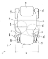
- FIG. 1 is a plan view showing a mowing vehicle 1 as an example of a work vehicle according to the present embodiment.
- the left side in FIG. 1 which is the traveling direction of the mowing vehicle 1 is defined as the front direction
- the upper side in FIG. The side is the left direction.
- the mowing vehicle 1 shown in FIG. 1 includes a traveling machine body 10 and a mowing apparatus 20 as a working machine.
- the traveling machine body 10 includes front wheels 12 (12R, 12L) on the left and right of the front part corresponding to the traveling direction of the machine body 11, and includes rear wheels 13 (13R, 13L) on the left and right of the rear part.
- a detachable battery 14 is provided at the rear part between 13R and 13L.
- the front wheel 12 is a driven wheel, and the rear wheel 13 is a driving wheel.
- the traveling machine body 10 also includes left and right traveling motors (not shown), left and right imaging devices 30 (30R, 30L) as first imaging devices capable of imaging the periphery of the traveling machine body 10, and the like. The operations of the traveling motor, the mowing device 20 and the left and right imaging devices 30 are controlled by a control unit C (not shown).
- the left and right rear wheels 13 (13R, 13L) and the left and right traveling motors are linked to each other via gears (not shown).
- the left and right traveling motors can independently rotate the left and right rear wheels 13R and 13L, which are drive wheels. Note that the electric power of the traveling motor is supplied from the battery 14.
- the left and right rear wheels 13R and 13L are independently rotated by the left and right traveling motors, whereby the mowing vehicle 1 can be moved forward, backward, turned, and the like.
- the left and right rear wheels 13R and 13L are rotated in the same direction and at the same speed.
- the right rear wheel 13R and the left rear wheel 13L are rotated at different speeds.
- the traveling machine body 10 is not limited to the above-described configuration.
- the traveling machine body 10 may include an engine as a prime mover, and the engine may travel by rotating the rear wheels 13 that are driving wheels by the engine.
- the traveling machine body 10 is configured to perform steering by causing a difference between the rotational speeds of the left and right rear wheels, and is configured to be steered by a steering device that can change the orientation of the front wheels 12 with respect to the machine body 10. Also good.
- the mowing device 20 is located between the front wheel 12 and the rear wheel 13 and below the airframe 11, and is suspended below the airframe 11 by a suspension device (not shown).
- the mowing device 20 can be moved up and down by this suspension device.
- the mowing vehicle 1 can adjust the mowing length of the grass by moving the mowing device 20 up and down.
- the mowing apparatus 20 includes a mower deck 21, left and right mower motors (not shown), and left and right mower blades 22 (22R and 22L) for mowing grass.
- the side surface of the rear part of the mower deck 21 is opened to discharge the cut grass to the rear.
- the left and right mower blades 22R and 22L are disposed adjacent to the inner side of the mower deck 21 and are rotated by the left and right mower motors, respectively.
- the grass can be cut by rotating the left and right mower blades 22R and 22L.
- the electric power of the mower motor is supplied from the battery 14.
- the operation of the mower motor is controlled by the control unit C.
- the mowing vehicle 1 can mow the grass with the mowing device 20 while traveling.
- the horizontal cutting width W in which the grass mowing device 20 cuts the grass during traveling is the right end of the rotation trajectory at the tip of the right mower blade 22R and the left end of the rotation trajectory at the tip of the left mower blade 22L.
- the width is approximately the same as the width of the mower deck in the left-right direction.
- the mowing apparatus 20 is not limited to the above-described configuration.
- the traveling machine body 10 may include an engine as a prime mover and the mower blade 22 may be rotated by the engine.
- the arrangement of the mowing apparatus 20 with respect to the traveling machine body 10, the shape of the mower deck 21, the number of mower blades 22 and the like can be designed as appropriate.
- the mowing apparatus 20 may be disposed in front of or behind the traveling machine body 10, and may be configured to discharge the cut grass in the left-right direction of the mower deck 21.
- the imaging device 30 (30R, 30L) is, for example, a CCD (Charge Coupled Device) camera.
- the left and right imaging devices 30 ⁇ / b> R and 30 ⁇ / b> L are attached to the tips of support brackets 31 that extend sideways and upward from the body 11.
- the left and right imaging devices 30 ⁇ / b> R and 30 ⁇ / b> L are installed with a depression angle and can image the ground in front of the traveling machine body 10.
- the right imaging device 30R is disposed corresponding to the right end of the operating portion of the mowing device 20, that is, the right end of the rotation locus of the tip of the right mower blade 22R. Therefore, the right imaging device 30 ⁇ / b> R is disposed corresponding to the right end portion of the area where the grass mowing device 20 cuts grass when traveling.
- the left imaging device 30L is disposed corresponding to the left end of the operating portion of the mowing device 20, that is, the left end of the rotation locus of the tip of the left mower blade 22L. Therefore, the left imaging device 30L is arranged corresponding to the left end of the area where the grass mowing device 20 cuts grass when traveling.
- control part C processes the image imaged by the imaging device 30, and detects the boundary line of the work trace formed sequentially by the mowing apparatus 20, ie, the boundary line before and after mowing the grass.
- the imaging device 30 only needs to be able to image the periphery of the traveling machine body 10, and the arrangement and mounting configuration can be designed as appropriate.
- FIG. 2 is a block diagram of detection of boundary lines of work traces and autonomous traveling control.
- the mowing vehicle 1 includes a storage unit M, a GNSS receiving device 41, an operation device 42, a display device 43, a communication device 44, a main body sensor 45, a mowing sensor 46, and the like in the traveling machine body 10.
- the imaging device 30, the storage unit M, the GNSS reception device 41, the operation device 42, the display device 43, the communication device 44, the main body sensor 45, the mowing sensor 46, and the like are connected to the control unit C.
- the control unit C reads input signals such as various set values and detection values from various sensors and outputs control signals to control operations of the traveling machine body 10, the mowing device 20, and the imaging device 30. And includes a processing device that performs arithmetic processing and control processing, a main storage device that stores information, and the like.
- the control unit C is, for example, a microcomputer including a CPU (Central Processing Unit) as a processing device, a ROM (Read Only Memory), a RAM (Random Access Memory), and the like as a main storage device.
- the main storage device stores a control program for executing the operation according to the present embodiment, various information, and the like.
- the various programs and information may be stored in the storage unit M and read by the control unit C.
- the storage unit M stores programs, information, and the like, and the stored information is rewritable, for example, a flash memory.
- the storage unit M stores in advance a route R described later along which the mowing vehicle 1 travels autonomously.
- the GNSS receiver 41 receives a radio signal from a GNSS satellite (not shown), converts the received radio signal, and transmits it to the control unit C.
- the operation device 42 is a mouse, a keyboard, or the like for inputting information, and inputs information such as a setting value related to autonomous traveling of the mowing vehicle 1.
- the display device 43 is a liquid crystal display or the like that displays information, and displays the status of arithmetic processing in the control unit C, information input by the operation device 42, information stored in the storage unit M, and the like.
- the communication device 44 transmits information to the outside and receives information from the outside. For example, the communication device 44 transmits information on the traveling state of the traveling machine body 10 and an image captured by the imaging device 30 to the outside. Therefore, it is possible to grasp the autonomous running state of the mowing vehicle 1 even in a remote place.
- the main body sensor 45 detects information on the operation of the traveling machine body 10.
- the mowing sensor 46 detects operation information of the mowing apparatus 20.
- the main body sensor 45 is a generic name of sensors for detecting information necessary for the autonomous traveling of the mowing vehicle 1 such as the traveling speed of the traveling machine body 10, the three-dimensional posture, and the rotational speed of the traveling motor. is there. More specifically, they are rotation sensors for left and right traveling motors, vehicle orientation sensors, vehicle tilt sensors, and the like. Detection signals from these main body sensors 45 are transmitted to the control unit C.
- the mowing sensor 46 is a sensor that detects the rotational speed of the mower motor, the raising / lowering position of the mower deck, and the detection signal from the mowing sensor 46 is transmitted to the control unit C.
- the control unit C has a position detection unit C1.
- the position detection unit C1 is configured by a program, for example.
- the position detection unit C1 is configured to calculate the position of the traveling machine body 10 based on radio signals transmitted at a certain time of a plurality of GNSS satellites input from the GNSS receiver 41.
- the control unit C further includes a boundary detection unit C2.
- the boundary detection unit C2 is configured by a program, for example.
- the boundary detection unit C2 performs boundary processing before and after grass cutting in an image captured by performing predetermined processing on an image signal (image) input from one of the left and right imaging devices 30 (30R, 30L). Is configured to detect.
- the predetermined processing performed on the image by the boundary detection unit C2 includes filtering processing, statistical processing, and the like.
- the boundary detection unit C2 performs a filtering process using a Gabor filter on the captured image input from the imaging device 30, and generates intensity distribution information related to texture information in a predetermined direction.
- the generated intensity distribution information is statistically processed to detect a boundary line before and after grass cutting.
- the Gabor filter is a filter that reacts to edges in a specific direction and is a feature extraction filter that is close to the human primary visual cortex.
- the Gabor filter is a filter defined by the product of a cosine wave and a Gaussian function.
- ⁇ is a wavelength
- ⁇ is an angle
- ⁇ is a phase
- ⁇ is an aspect ratio
- ⁇ is a parameter indicating a standard deviation.
- the control unit C further includes a first travel control unit C3.
- the first travel control unit C3 is configured by a program, for example. Although the details will be described later, the first traveling control unit C3 is configured to control the traveling direction of the traveling machine body 10 along the boundary line before and after cutting the grass detected by the boundary detecting unit C2. . That is, the first traveling control unit C3 changes the traveling direction of the traveling machine body 10 by controlling the operation of the traveling motor based on the boundary line detected by the boundary detecting unit C2, and travels along the boundary line.
- the vehicle body 10 is configured to travel.
- the control unit C further includes a second travel control unit C4.
- the second traveling control unit C4 is configured by a program, for example.
- the second travel control unit C4 travels based on the position of the traveling machine body 10 detected by the position detection unit C1, the route R stored in advance in the storage unit M, and the detection signal from the main body sensor 45.
- the traveling direction of the traveling machine body 10 is changed by controlling the operation of the motor, and the traveling machine body 10 is caused to travel along the route R stored in the storage unit M in advance.
- FIG. 3 is a schematic plan view showing an example of a route R for autonomous traveling of the mowing vehicle 1.
- the arrow in FIG. 3 shows the advancing direction of the mowing vehicle 1.
- the route R on which the mowing vehicle 1 travels autonomously is set in advance and is stored in the storage unit M in advance.
- the mowing vehicle 1 is configured to autonomously travel along the route R.
- the route R is configured to reciprocate in a straight line in the work place 50, and the mowing vehicle 1 performs grass cutting work by the grass cutting device 20 while autonomously traveling on the route R. do.
- the path R includes a plurality of linear parallel paths R1 (R1a to R1f) having a predetermined interval in parallel, and a plurality of semicircular turning paths R2 (R2a to R2e) connecting the adjacent parallel paths R1. Consists of The interval between the adjacent parallel paths R1 is substantially the same as the cutting width W of the mowing device 20, and is appropriately designed according to the dimensions of the mowing device 20.
- the mowing vehicle 1 travels on the parallel route R1a from the travel start point 51, turns 180 degrees by traveling on the turning route R2a at the end of the work place 50, and is adjacent to the parallel route R1a that traveled last time. Drive on R1b.
- the mowing vehicle 1 travels to the travel end point 52 by repeating such reciprocating travel, and cuts the grass in the work place 50.
- the interval between the adjacent parallel paths R1 is substantially the same as the cutting width W of the mowing device 20
- the travel of the mowing vehicle 1 on the parallel paths R1b to R1f excluding the parallel path R1a from the travel start point 51 is It travels in a state adjacent to the area where the grass is cut.
- the interval between adjacent parallel paths R1 is preferably narrower than the cutting width W of the mowing device 20.
- the mowing device 20 travels with a region where the grass has already been cut and a lapping allowance, so that no grass is left uncut between the adjacent parallel paths R1.
- the route R does not have to have all position information on the route.
- the route R has a travel start point 51, a travel end point 52, position information on the start and end points of each turning route R2, and information on the turning radius on each turning route R2.
- the mowing vehicle 1 travels autonomously from the travel start point 51 to the end of the turn route R2a along the parallel route R1a and the turn route R2a.
- the mowing vehicle 1 performs autonomous traveling by the second traveling control unit C4 on the parallel route R1a and the turning route R2a.
- the mowing vehicle 1 is moved by the second traveling control unit C4.
- a deviation amount between the parallel route R1a and the traveling machine body 10 is calculated.
- the deviation amount for example, as shown in FIG. 4, the deviation distance L1 from the parallel path R1a at the center of the traveling machine body 10, the deviation angle ⁇ 1 between the direction (traveling direction) of the traveling machine body 10 and the parallel path R1a, etc. It is.
- FIG. 4 is a schematic plan view for explaining an example of the deviation between the traveling machine body 10 and the route R, and the arrows in FIG. 4 indicate the traveling direction of the traveling machine body 10.
- the mowing vehicle 1 further changes the traveling direction of the traveling machine body 10 by controlling the operation of the traveling motor based on the calculated deviation between the parallel path R1a and the traveling machine body 10 by the second traveling control unit C4.
- the traveling machine body 10 is caused to travel along the parallel path R1a.
- the detection of the position of the traveling machine body 10 by the position detection unit C1 and the change of the traveling direction of the traveling machine body 10 by the second traveling control unit C4 are performed at a predetermined sampling cycle, for example, at a cycle of 1 second. .
- the traveling route R2a When the mowing vehicle 1 reaches the starting point of the turning route R2a (the end point of the parallel route R1a), the position of the traveling machine body 10 detected by the position detection unit C1, the turning route R2a, and a detection signal from the main body sensor 45. Based on the above, the operation of the traveling motor is controlled by the second traveling control unit C4 to change the traveling direction of the traveling body 10, and the traveling body 10 travels along the turning route R2a.
- the turning route R2a has a semicircular shape with a predetermined radius (W / 2), the mowing vehicle 1 only turns 180 degrees to the left.
- the mowing vehicle 1 can cause the traveling machine body 10 to travel along the turning route R2a only by controlling the traveling motor to a predetermined operation by the second control unit C4.
- the second traveling control unit C4 calculates the deviation amount between the turning route R2a and the traveling machine body 10 along the turning route R2a and calculates the deviation amount between the turning route R2a and the traveling machine body 10 in the turning route R2a. It may be configured to run.
- the traveling of the mowing vehicle 1 on the parallel route R1b travels in a state adjacent to the area where the grass is cut off when traveling on the parallel route R1a. That is, the travel of the mowing vehicle 1 on the parallel path R1b is a boundary line between the area where the grass is cut when traveling on the parallel path R1a and the area where the grass is not yet cut which is scheduled to be harvested when traveling on the parallel path R1b. It travels along (the boundary line before and after mowing the grass).
- the mowing vehicle 1 performs autonomous traveling by the first traveling control unit C3 on the parallel route R1b.
- the mowing vehicle 1 detects the boundary line before and after the cutting of the grass by the boundary detection unit C2, and based on the detected boundary line before and after the cutting of the grass, the first traveling control unit C3 controls the operation of the traveling motor.
- the traveling direction of the traveling machine body 10 is changed by control, and the traveling machine body 10 travels along the boundary line, thereby autonomously traveling on the parallel route R1b.
- the detection of the boundary line by the boundary detection unit C2 and the change of the traveling direction of the traveling machine body 10 by the first traveling control unit C3 are the same as in the case of the above-described position detecting unit C1 and second traveling control unit C4. This is performed at a predetermined sampling cycle, for example, at a cycle of 1 second. Further, even when the mowing vehicle 1 is traveling on the parallel route R1b, the position detection unit C1 detects the position of the traveling machine body 10 at a predetermined sampling period.
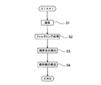
- FIG. 5 is a flowchart for explaining an example of the detection operation of the boundary detection unit C2.
- the mowing vehicle 1 images the front of the mowing vehicle 1 with the left imaging device 30L on the side where the boundary line before and after mowing the grass is located (step S1).
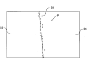
- a schematic diagram of an example of a captured image is shown in FIG.
- FIG. 6 shows a boundary line 55 between a region 53 where grass is cut and a region 54 where grass is not cut.
- the captured image is composed of 480 ⁇ 640 pixels, and luminance information of each of the 480 ⁇ 640 pixels is input to the boundary detection unit C2.
- the left and right imaging devices 30 are arranged corresponding to the right end and the left end of the area where the grass is cut by the grass mowing device 20, respectively.
- the center in the left-right direction of each image captured by () corresponds to the right end and the left end of the area where the grass mowing device 20 cuts grass. Therefore, the direction of the traveling machine body 10 is parallel to the boundary line 55 between the area 53 where the grass is cut and the area 54 where the grass is not cut, and the rotation trajectory of the tip of the left mower blade 22L of the mowing apparatus 20
- the boundary line 55 is positioned at the center in the left-right direction in the image captured by the left imaging device 30L. That is, when the left imaging device 30L travels on the parallel route R1b, the left imaging device 30L is arranged such that the boundary line 55 is positioned at the center in the left-right direction of the image to be captured.
- the boundary detection unit C2 performs a filtering process using a Gabor filter on the image captured by the left imaging device 30L (step S2).
- the grass extends upward from the ground, and the boundary line before and after cutting the grass is a boundary line in a region where the texture pattern differs depending on the length of grass and the direction of extension.
- the area before and after cutting the grass has different image characteristics in the vertical direction, and the boundary of this vertical characteristic can be recognized as the boundary before and after the cutting of the grass. .
- the image that has been subjected to Gabor filter processing is intensity distribution information in the upward direction.
- Each parameter is not limited to the above, and can be designed as appropriate.
- the noise removal filter is not particularly limited, and may be, for example, a gray scale conversion of a color image or a median filter that replaces the value of each pixel with the median value of surrounding pixels.
- the boundary detection unit C2 detects a boundary point located on the boundary line 55 before and after mowing the grass for the image subjected to the Gabor filter process (step S3).
- a plurality of inspection areas are set by dividing an image that has been subjected to Gabor filter processing in the vertical direction. Further, a plurality of unit inspection areas are set by dividing each inspection area in the left-right direction.
- the image subjected to the Gabor filter process is equally divided in the vertical direction, and 30 inspection areas are set. Further, each inspection area is equally divided in the left-right direction, and 40 unit inspection areas are set for each. That is, the image subjected to the Gabor filter process is divided into a total of 1200 unit inspection areas.
- the boundary detection unit C2 calculates the sum of luminance in each unit inspection area. Further, the boundary detection unit C2 calculates an average value of the sum of the luminances of the 40 unit inspection areas in each inspection area, and uses the average value as a threshold value of the inspection area. Then, for each inspection region, the boundary detection unit C2 divides the threshold value from the sum of luminance in the unit inspection region from left to right, and compares the positive and negative values with the previous divided value to determine the boundary point. . The boundary detection unit C2 determines the center of the unit inspection area as the boundary point when the value of the divided value is different from the value of the previous divided value.
- FIG. 7 is a schematic diagram showing an example of a plurality of detected boundary points P in the schematic diagram of the image in FIG.
- the threshold value used when determining the boundary point is calculated for each inspection region and does not need to be set in advance. Therefore, it is difficult to be influenced by the state of grass, the state of light, the brightness, the rule of thumb, etc., and the boundary point can be determined more reliably.
- the boundary point detection method is not limited to the above-described configuration. It is only necessary to be able to detect boundary points located on the boundary line before and after mowing the grass from the image that has been subjected to Gabor filter processing, which is intensity distribution information in a predetermined direction, and the inspection area, the size of the unit inspection area, and the threshold value
- the determination method and the like are appropriately designed.
- the unit inspection area may be set so as to overlap with the left and right other unit inspection areas.
- the threshold value may be calculated using a simple moving average in the left-right direction, or one threshold value may be determined for each image.
- the left and right imaging devices 30 ⁇ / b> R and 30 ⁇ / b> L are arranged corresponding to the right end and the left end of the area where the grass mowing device 20 cuts grass, respectively. Therefore, in the images captured by the left and right imaging devices 30R and 30L, the boundary line 55 is configured to be easily captured at a substantially center in the left-right direction. Accordingly, a configuration may be adopted in which the boundary point is detected with respect to the region of the central portion in the left-right direction of the image subjected to the Gabor filter processing. With this configuration, it is possible to reduce the calculation amount of the boundary detection unit C2.
- the size of the unit inspection area located in the center portion may be set small, and the size of the unit inspection areas located in the right side portion and the left side portion may be set large. With this setting, the calculation amount of the boundary detection unit C2 can be reduced.
- the average value of the threshold values calculated for each inspection region is stored in the storage unit M, and when the boundary point is detected from the image captured by the imaging device 30 next time, the average value of the threshold values stored in the storage unit M is used.
- the configuration may be such that a boundary point is detected as a threshold value.
- the boundary detection unit C2 can reduce the calculation amount of the boundary detection unit C2 without calculating the threshold value every time.
- the boundary detection unit C2 detects the boundary point by calculating a threshold when detecting the next boundary point according to the number of boundary points as outliers described later. Also good. This is because the threshold value may not be appropriate when the number of boundary points as an outlier is large. Therefore, with such a configuration, the boundary point can be detected more accurately.
- the threshold value used when determining the boundary point may be set in advance.
- the boundary detection unit C2 detects the boundary line 55 before and after mowing the grass based on the detected boundary point P for each inspection region (step S4).
- the boundary point P for each inspection region detected in step S ⁇ b> 3 may include a point greatly deviating from the boundary line 55. Therefore, the boundary detection unit C2 extracts boundary points P included in a predetermined error range, and detects the boundary line 55 based on the extracted plurality of boundary points P.
- the boundary detection unit C2 extracts a boundary point P included in a predetermined error range using RANSAC (RANdam SAmple Consensus). More specifically, the boundary detection unit C2 randomly selects two boundary points P from all the boundary points P detected in step S3, and calculates a straight line passing through the two boundary points P. The boundary detection unit C2 calculates the distance between the calculated straight line and all the boundary points P detected in step S3, and extracts only the boundary point P whose distance is smaller than a predetermined threshold. Next, the boundary detection unit C2 randomly selects two boundary points from the extracted boundary point P, calculates a straight line passing through the two boundary points P, and calculates the calculated value.
- RANSAC Random SAmple Consensus
- the distance between the straight line and all the extracted boundary points P is calculated, and only the boundary point P whose distance is smaller than a predetermined threshold is newly extracted. Then, the boundary detection unit C2 repeats the above-described extraction of the boundary points a plurality of times, so that the boundary points P included in the predetermined error range (within the threshold value) from all the boundary points P detected in step S3. Extract. In the present embodiment, the number of repetitions of this extraction is 50.
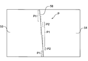
- FIG. 8 is a schematic diagram showing an example of a plurality of detected boundary points P and detected boundary lines 56 in the schematic diagram of the image in FIG.
- a boundary point P1 indicates a boundary point P1
- a boundary point P2 indicates an outlier that is not used for boundary line detection.
- the description of the captured boundary line 55 is omitted.
- the detection method of the boundary line 55 is not limited to the above-described configuration, and the number of repetitions and the threshold value to be extracted from the boundary point P are appropriately designed.
- the boundary point P may be extracted using a method different from RANSAC, and for example, the boundary point P may be extracted by a least square method.
- the least square method since there is no stability against disturbance (outlier), it is preferable to use an extraction method having robustness.
- the boundary detection unit C2 is configured to detect the boundary line based on the upward intensity distribution information generated by the filtering process using the upward Gabor filter from the captured image. That is, since the boundary detection unit C2 is configured to perform filtering processing using one Gabor filter, the amount of information to be statistically processed does not increase, and the boundary line can be detected with a simple configuration. it can.
- ⁇ which is a parameter of the direction (angle)
- ⁇ is set to 0, 15, 30, 45, 60, 75, 90, 105, 120, 135, 150, 165.
- 36 Gabor filters having standard deviations ⁇ with respect to ⁇ of 1.2, 1.6, and 2.2 are used.
- the filtering process using the 36 Gabor filters is performed on the captured image.
- intensity information in each direction is generated for each pixel. That is, 36 pieces of intensity information are generated for each pixel.
- the intensity information of each pixel is a value obtained by adding the product of the luminance of each pixel and the value calculated by the filtering process to the luminance of each pixel.
- the maximum one is extracted from the 36 pieces of intensity information, and the direction ( ⁇ ) of the Gabor filter in which the maximum intensity information is generated is used as the texture information in the pixel.
- Generate distribution information In this way, the texture pattern in the captured image can be extracted as texture distribution information.
- the information (image) generated by the binarization process is an image obtained by dividing the captured image into a region where grass is cut and a region where grass is not cut.
- the boundary line can be detected based on the intensity distribution information regarding the texture information in a plurality of directions, and the boundary line can be detected more accurately.
- the boundary line detection method using a plurality of Gabor filters is not limited to the above-described configuration.
- a configuration may be adopted in which filtering processing for removing noise is performed on an image generated by binarization processing. With such a configuration, the boundary point can be detected more accurately.
- the number of Gabor filters, the value of each parameter, the threshold value and the like are not limited to the above, and can be appropriately designed.
- the binarization process similar to the above is applied to the intensity distribution information generated by the filtering process, and the boundary point is determined based on the image generated by the binarization process. It can also be configured to detect.
- the mowing vehicle 1 travels by controlling the operation of the travel motor by the first travel control unit C3 based on the detection boundary line 56 before and after cutting the grass detected by the boundary detection unit C2 as described above.
- the traveling direction of the body 10 is changed, and autonomous traveling is performed along the boundary line.
- the deviation amount between the detection boundary line 56 and the traveling machine body 10 is calculated by the first traveling control unit C3.
- the deviation amount for example, as shown in FIGS. 9 and 10, the deviation distance L2 in the left-right direction between the reference point O of the image captured by the left imaging device 30L and the detected detection boundary line 56, and detection The deviation angle ⁇ 2 of the inclination of the detected boundary line 56 with respect to the vertical direction.
- FIG. 9 is a schematic diagram for explaining an example of the deviation between the detected boundary line 56 and the traveling machine body 10
- FIG. 10 shows the deviation of the detected boundary line 56 and the traveling machine body 10. It is a schematic plan view for demonstrating an example.
- FIG. 10 shows the detection boundary line 56a, the reference point Oa, the deviation distance L2a, and the deviation angle respectively corresponding to the detected detection boundary line 56, the reference point O, the deviation distance L2, and the deviation angle ⁇ 2 in FIG. ⁇ 2a is shown, an area 57 indicates an area displayed in the image, and an arrow indicates a traveling direction of the traveling machine body 10.
- the deviation distance L2 and deviation angle ⁇ 2 (in the image) in FIG. 9 are different from the deviation distance L2a and deviation angle ⁇ 2a (in real space) in FIG.
- the traveling control unit C3 of No. 1 uses a deviation distance L2 and a deviation angle ⁇ 2 calculated from the detection boundary line 56 detected by the boundary detection unit C2 and converted into a deviation distance L2a and a deviation angle ⁇ 2a by coordinate conversion.
- the direction of the traveling machine body 10 is parallel to the boundary line 55 before and after mowing the grass, and the left end of the rotation locus of the left mower blade 22L of the mowing device 20 is When positioned on the boundary line, the boundary line 55 is arranged at the center in the left-right direction of the captured image. Therefore, the first traveling control unit C3 can relatively easily calculate the deviation amount between the detected detection boundary line 56 and the traveling machine body 10 with reference to the center in the left-right direction of the image. The amount of calculation of the part C3 can be reduced.
- the mowing vehicle 1 further controls the operation of the traveling motor based on the detected deviation amount (deviation distance L2a, deviation angle ⁇ 2a) between the boundary line 56 and the traveling machine body 10 by the first traveling control unit C3.
- the traveling direction of the traveling machine body 10 is changed, and autonomous traveling is performed along the boundary line before and after mowing the grass.
- the position of the traveling machine body 10 detected by the position detection unit C1 and the turning route R2b are the same as the traveling of the turning route R2b described above.
- the operation of the traveling motor is controlled by the second traveling control unit C4 to change the traveling direction of the traveling body 10, and the traveling body 10 travels along the turning route R2b.
- the turning route R2b for the right turn is different from the turning route R2a for the left turn only in the turning direction.
- the mowing vehicle 1 causes the traveling machine body 10 to travel along the turning route R2b only by controlling the traveling motor to a predetermined operation by the second control unit C4, similarly to the traveling of the turning route R2a. Can do.
- the second traveling control unit C4 calculates the deviation amount between the turning route R2b and the traveling machine body 10 along the turning route R2b and calculates the deviation amount between the turning route R2b and the traveling vehicle body 10 in the turning route R2b as well as the parallel route R1b described above. It may be configured to run.
- the mowing vehicle 1 when it reaches the end point of the turning route R2b (starting point of the parallel route R1c), it automatically travels along the parallel route R1c to the end point of the parallel route R1c (starting point of the turning route R2c).
- the traveling of the mowing vehicle 1 on the parallel path R1c is similar to the above-described parallel path R1b.
- the area where the grass is cut when traveling on the parallel path R1b and the grass that is scheduled to cut the grass when traveling on the parallel path R1c are used.
- the vehicle travels along a boundary line (a boundary line before and after cutting the grass) with a region that is not cut.
- the grass cutting vehicle 1 detects the boundary line before and after cutting the grass by the boundary detection unit C2, similarly to the traveling of the parallel path R1b described above, and based on the detected boundary line before and after cutting the grass, A traveling control unit C3 controls the operation of the traveling motor to change the traveling direction of the traveling machine body 10 and causes the traveling machine body 10 to travel along the boundary line, thereby autonomously traveling on the parallel route R1c.
- the boundary detection unit C2 detects a boundary line before and after mowing the grass based on the image captured by the right imaging device 30L.
- the boundary detection unit C2 detects the boundary line before and after cutting the grass
- the first traveling control unit C3 changes the traveling direction of the traveling machine body 10 when traveling on the parallel route R1b.
- the imaging device 30 that captures the image is different between right and left, and the description thereof is omitted.
- switching between the left and right imaging devices 30R and 30L is determined by the route R, and information on which left and right imaging devices 30R and 30L are used is stored in the storage unit M in association with the route R in advance. ing.
- the boundary detection unit C2 determines whether there is a boundary line, and which of the left and right imaging devices 30R and 30L is used based on the determination result. It is also possible to adopt a configuration for determining With such a configuration, the amount of information stored in the storage unit M in advance can be reduced. In addition, even when the traveling machine body 10 deviates greatly from the route R, it becomes possible to continue autonomous traveling, and work efficiency is improved.
- the mowing vehicle 1 sequentially travels on the turning route R2 that connects the adjacent parallel route R1 and the parallel route R1, and ends the autonomous traveling when it reaches the traveling end point 52.
- the traveling of the mowing vehicle 1 on the parallel routes R1b to R1f excluding the parallel route R1a from the travel start point 51 travels in a state adjacent to the area where the grass is cut, and the mowing vehicle 1 It autonomously travels along a boundary line before and after mowing grass that is sequentially formed by the device 20. Therefore, no uncut grass remains between the adjacent parallel paths R1.
- the Gabor filter process is performed by a Gabor filter only in a specific direction (upward direction), the calculation amount of the boundary detection unit C2 does not increase.
- the boundary line can be detected more accurately with a simple configuration. Further, since the left and right imaging devices 30R and 30L are arranged so that the boundary line is located at the approximate center in the left and right direction of the image when the mowing vehicle 1 travels along the boundary line, It can prevent that a boundary line becomes difficult to be imaged. Further, the imaging device 30 does not require complicated calibration and is not easily restricted by the installation position.
- the mowing vehicle 1 as a work vehicle is not limited to the above-described configuration.
- the mowing vehicle 1 in addition to the right imaging devices 30R and 30L, the mowing vehicle 1 travels as a second imaging device.
- the structure provided with the imaging device 32 (32R, 32L) on either side which can image the back of the body 10 may be sufficient.
- FIG. 11 is a schematic plan view showing a mowing vehicle 2 as an example of a work vehicle according to another embodiment.
- the mowing vehicle 2 has the same configuration as the mowing vehicle 1 described above except for the left and right imaging devices 32 (32R, 32L).
- the image pickup device 32 (32R, 32L) picks up an image of a boundary line before and after the grass cutting immediately after the grass cutting of the grass cutting device 20 as a working machine. With this configuration, it is possible to reduce the amount of calculation of the boundary detection unit C2 when detecting the boundary line before and after mowing the grass based on the image captured by the imaging device 30 (30R, 30L). . In addition, the boundary line can be detected more accurately.
- the boundary detection unit C2 detects the boundary line 58 before and after mowing the grass based on the image captured by the left imaging device 30L.
- the mowing vehicle 2 images the boundary line 59 before and after mowing the grass immediately after mowing the grass mowing device 20 with the right imaging device 32R at any point on the route R1b.
- the boundary detection unit C2 performs a filtering process using a Gabor filter on the image captured by the right imaging device 32R in the same manner as the detection of the boundary line.
- the boundary detection unit C2 sets a plurality of inspection areas and a plurality of unit inspection areas in the same manner as the detection of the boundary lines for the image subjected to the Gabor filter processing. Further, the average value of the sum of the luminances of the unit inspection areas in each inspection area is calculated, the average value of the total sum of the average values of the calculated inspection areas is calculated, and this average value is used as a threshold value for the next process. To store.
- the image picked up by the right image pickup device 32R is an image picked up from the same direction as the image picked up by the right image pickup device 30R when traveling on the route R1c of the next process. That is, the mowing vehicle 2 is configured to previously capture an image (an image in which the boundary line 59 is captured) when traveling on the route R1c of the next process with the right imaging device 32R.
- the threshold value of the next process stored in the storage unit M is used for detection of a boundary line by the boundary detection unit C2 when traveling on the route R1c.
- the boundary detection unit C2 detects the boundary line 59 before and after mowing the grass based on the image captured by the right imaging device 30R (when traveling along the route R1c as the next step), and the threshold value of the boundary point
- the threshold value of the next process stored in the storage unit M when traveling on the route R1b is used. Therefore, the boundary detection unit C2 does not need to calculate the threshold value of the boundary point when traveling on the route R1c, which is the next step, and can reduce the calculation amount of the boundary detection unit C2.
- this threshold value is calculated from images taken from the same direction, the boundary detection unit C2 can detect the boundary point more accurately. Therefore, the boundary detection unit C2 can detect the boundary line more accurately.
- the mowing vehicles 1 and 2 may be configured so that the boundary line before and after mowing the grass can be captured by the imaging device, and is not limited to the configuration including the imaging devices on the left and right.
- the mowing vehicle 1 may be configured to include only one imaging device that images the front of the traveling machine body 10, and the mowing vehicle 2 includes one imaging device that images the front and one imaging device that captures the rear. It may be the composition provided. With such a configuration, the number of imaging devices is reduced, and the productivity of the mowing vehicles 1 and 2 is improved.
- the route R on which the mowing vehicles 1 and 2 travel autonomously is not limited to the above-described configuration, and the route R travels along a boundary line before and after mowing the grass that is sequentially formed by the mowing device 20. I need it.
- the path R may be a spiral path having a predetermined distance from an adjacent path.
- the combination of the traveling machine body and the working machine in the work vehicle of the present invention is not limited to the combination of the traveling machine body 10 and the grass cutting device 20 in the above-described mowing vehicles 1 and 2.
- it may be a work vehicle including a rotary tiller as a work machine at the rear of the traveling machine body. Since the work vehicle having such a configuration travels while plowing the topsoil of the work site using the rotary tiller, traces of sequential plowing are formed. Therefore, the work vehicle having such a configuration, like the mowing vehicles 1 and 2 described above, captures the boundary line before and after tilling of the rotary tiller with the imaging device and detects based on the image captured by the boundary detection unit. Thus, it is possible to autonomously travel along this boundary line.
- a work vehicle including a seedling planting device as a work machine at the rear of the traveling machine body may be used. Since the work vehicle having such a configuration travels while planting seedlings on the work site by the seedling planting device, seedlings are sequentially planted as work traces. Here, the seedlings are planted in strips. Therefore, the work vehicle having such a configuration, like the above-described configuration of the mowing vehicles 1 and 2, picks up an image of seedlings (rows of seedlings) as a boundary line before and after planting of the seedling planting device, and detects the boundary. By detecting the seedling (the seedling strip) based on the image picked up by the unit, it is possible to autonomously travel along the seedling (the seedling strip) as the boundary line.
- the work vehicle of the present invention is not limited to a combination of a traveling machine body and a mowing device, a combination of a traveling machine body and a rotary tiller, and the like.
- the present invention can be applied to any work vehicle in which work traces are sequentially formed on the work site by the work machine provided.
Abstract
Description
走行機体と作業機とを備え、走行しながら作業を行う作業車両であり、
前記走行機体の周辺を撮像する第1の撮像装置と、
前記作業機によって逐次形成される作業痕跡の境界線に沿って、前記走行機体を自律走行させるように制御する制御部と、を備え、
前記制御部は、
前記第1の撮像装置によって撮像された画像を処理して、前記境界線を検出する境界検出部と、
前記境界検出部によって検出された境界線に沿うように、前記走行機体の走行方向を制御する走行制御部とを有し、
前記境界検出部は、
撮像された前記画像からガボールフィルタを用いたフィルタリング処理によって、所定の方向のテクスチャー情報に関する強度分布情報を生成し、
前記強度分布情報を、上下方向に複数に分割された検査領域毎に、統計処理して境界点を検出し、
前記検査領域毎の前記境界点から前記境界線を検出するように構成されていることを特徴とする。 In order to solve the above problems, a work vehicle according to the present invention includes:
A work vehicle that includes a traveling machine body and a work machine and that performs work while traveling,
A first imaging device for imaging the periphery of the traveling machine body;
A control unit that controls the traveling machine body to autonomously travel along a boundary line of work traces sequentially formed by the working machine,
The controller is
A boundary detection unit for processing the image captured by the first imaging device and detecting the boundary line;
A travel control unit that controls the travel direction of the traveling machine body along the boundary line detected by the boundary detection unit;
The boundary detection unit
Intensity distribution information regarding texture information in a predetermined direction is generated from the captured image by a filtering process using a Gabor filter,
The intensity distribution information is statistically processed for each inspection region divided into a plurality of vertical directions to detect boundary points,
The boundary line is detected from the boundary point for each inspection region.
前記制御部は、前記右側端部または前記左側端部のいずれか一方の前記第1の撮像装置によって撮像された画像を処理するように構成されていることを特徴とする。 Furthermore, the first imaging device is provided corresponding to the right end and the left end of the work implement,
The control unit is configured to process an image captured by the first imaging device at either the right end or the left end.
前記制御部は、
前記第2の撮像装置によって撮像された画像からガボールフィルタを用いたフィルタリング処理によって、前記所定の方向のテクスチャー情報に関する別の強度分布情報を生成し、
前記別の強度分布情報を、上下方向に複数に分割された検査領域毎に、統計処理して得られる処理結果を前記記憶部に格納し、
後に前記第1の撮像装置によって撮像された画像を処理して前記境界線を検出する際の前記統計処理において、前記記憶部に格納された前記処理結果を用いるように構成されていることを特徴とする。 A second imaging device capable of imaging a work trace immediately after the work of the work machine, and a storage unit;
The controller is
Generate another intensity distribution information related to the texture information in the predetermined direction by a filtering process using a Gabor filter from the image captured by the second imaging device,
The other intensity distribution information is stored in the storage unit for processing results obtained by statistical processing for each inspection region divided into a plurality of vertical directions,
In the statistical processing when the image picked up by the first image pickup device is processed later to detect the boundary line, the processing result stored in the storage unit is used. And

10 走行機体
20 草刈装置
30 撮像装置(第1の撮像装置)
32 撮像装置(第2の撮像装置)
C 制御部
C1 位置検出部
C2 境界検出部
C3 第1の走行制御部(走行制御部)
C4 第2の走行制御部
M 記憶部
1, 2 Mowing vehicle (work vehicle)
DESCRIPTION OF
32 imaging device (second imaging device)
C control unit C1 position detection unit C2 boundary detection unit C3 first travel control unit (travel control unit)
C4 second traveling control unit M storage unit
Claims (5)
- 走行機体と作業機とを備え、走行しながら作業を行う作業車両であり、
前記走行機体の周辺を撮像する第1の撮像装置と、
前記作業機によって逐次形成される作業痕跡の境界線に沿って、前記走行機体を自律走行させるように制御する制御部と、
を備え、
前記制御部は、
前記第1の撮像装置によって撮像された画像を処理して、前記境界線を検出する境界検出部と、
前記境界検出部によって検出された境界線に沿うように、前記走行機体の走行方向を制御する走行制御部とを有し、
前記境界検出部は、
撮像された前記画像からガボールフィルタを用いたフィルタリング処理によって、所定の方向のテクスチャー情報に関する強度分布情報を生成し、
前記強度分布情報を、上下方向に複数に分割された検査領域毎に、統計処理して境界点を検出し、
前記検査領域毎の前記境界点から前記境界線を検出するように構成されていることを特徴とする、作業車両。 A work vehicle that includes a traveling machine body and a work machine and that performs work while traveling,
A first imaging device for imaging the periphery of the traveling machine body;
A control unit for controlling the traveling machine body to autonomously travel along a boundary line of work traces sequentially formed by the working machine;
With
The controller is
A boundary detection unit for processing the image captured by the first imaging device and detecting the boundary line;
A travel control unit that controls the travel direction of the traveling machine body along the boundary line detected by the boundary detection unit;
The boundary detection unit
Intensity distribution information regarding texture information in a predetermined direction is generated from the captured image by a filtering process using a Gabor filter,
The intensity distribution information is statistically processed for each inspection region divided into a plurality of vertical directions to detect boundary points,
A work vehicle configured to detect the boundary line from the boundary point for each inspection region. - 前記所定の方向は、上方向または下方向であることを特徴とする、
請求項1に記載の作業車両。 The predetermined direction is an upward direction or a downward direction,
The work vehicle according to claim 1. - 前記第1の撮像装置は、撮像する画像の左右方向略中央に前記作業痕跡の前記境界線が位置するように配置されることを特徴とする、
請求項1に記載の作業車両。 The first imaging device is arranged so that the boundary line of the work trace is positioned at approximately the center in the left-right direction of the image to be captured.
The work vehicle according to claim 1. - 前記第1の撮像装置を、前記作業機の右側端部と左側端部にそれぞれ対応して備え、
前記制御部は、前記右側端部または前記左側端部のいずれか一方の前記第1の撮像装置によって撮像された画像を処理するように構成されていることを特徴とする、
請求項1に記載の作業車両。 The first imaging device is provided corresponding to the right end and the left end of the work implement,
The control unit is configured to process an image captured by the first imaging device at either the right end or the left end.
The work vehicle according to claim 1. - 前記作業機の作業直後の作業痕跡を撮像可能な第2の撮像装置と、記憶部と、を更に備え、
前記制御部は、
前記第2の撮像装置によって撮像された画像からガボールフィルタを用いたフィルタリング処理によって、前記所定の方向のテクスチャー情報に関する別の強度分布情報を生成し、
前記別の強度分布情報を、上下方向に複数に分割された検査領域毎に、統計処理して得られる処理結果を前記記憶部に格納し、
後に前記第1の撮像装置によって撮像された画像を処理して前記境界線を検出する際の前記統計処理において、前記記憶部に格納された前記処理結果を用いるように構成されていることを特徴とする、
請求項1に記載の作業車両。
A second imaging device capable of imaging a work trace immediately after the work of the work machine, and a storage unit;
The controller is
Generate another intensity distribution information related to the texture information in the predetermined direction by a filtering process using a Gabor filter from the image captured by the second imaging device,
The other intensity distribution information is stored in the storage unit for processing results obtained by statistical processing for each inspection region divided into a plurality of vertical directions,
In the statistical processing when the image picked up by the first image pickup device is processed later to detect the boundary line, the processing result stored in the storage unit is used. And
The work vehicle according to claim 1.
Priority Applications (4)
| Application Number | Priority Date | Filing Date | Title |
|---|---|---|---|
| US15/534,617 US10274963B2 (en) | 2014-12-11 | 2015-12-10 | Work vehicle |
| KR1020177015874A KR102017965B1 (en) | 2014-12-11 | 2015-12-10 | Work vehicle |
| EP15866771.7A EP3232290B1 (en) | 2014-12-11 | 2015-12-10 | Work vehicle |
| ES15866771T ES2759793T3 (en) | 2014-12-11 | 2015-12-10 | Work vehicle |
Applications Claiming Priority (2)
| Application Number | Priority Date | Filing Date | Title |
|---|---|---|---|
| JP2014-250953 | 2014-12-11 | ||
| JP2014250953A JP2016114984A (en) | 2014-12-11 | 2014-12-11 | Work vehicle |
Publications (1)
| Publication Number | Publication Date |
|---|---|
| WO2016093311A1 true WO2016093311A1 (en) | 2016-06-16 |
Family
ID=56107488
Family Applications (1)
| Application Number | Title | Priority Date | Filing Date |
|---|---|---|---|
| PCT/JP2015/084652 WO2016093311A1 (en) | 2014-12-11 | 2015-12-10 | Work vehicle |
Country Status (6)
| Country | Link |
|---|---|
| US (1) | US10274963B2 (en) |
| EP (1) | EP3232290B1 (en) |
| JP (1) | JP2016114984A (en) |
| KR (1) | KR102017965B1 (en) |
| ES (1) | ES2759793T3 (en) |
| WO (1) | WO2016093311A1 (en) |
Cited By (1)
| Publication number | Priority date | Publication date | Assignee | Title |
|---|---|---|---|---|
| JP2018102204A (en) * | 2016-12-26 | 2018-07-05 | 本田技研工業株式会社 | Working machine |
Families Citing this family (20)
| Publication number | Priority date | Publication date | Assignee | Title |
|---|---|---|---|---|
| CN109874488B (en) | 2016-06-30 | 2022-04-01 | 创科(澳门离岸商业服务)有限公司 | Autonomous mower and navigation system thereof |
| US11172607B2 (en) | 2016-06-30 | 2021-11-16 | Tti (Macao Commercial Offshore) Limited | Autonomous lawn mower and a system for navigating thereof |
| JP6734183B2 (en) * | 2016-11-25 | 2020-08-05 | 本田技研工業株式会社 | Work machine |
| JP6673862B2 (en) * | 2017-03-03 | 2020-03-25 | ヤンマー株式会社 | Travel route identification system |
| JP6908510B2 (en) * | 2017-12-07 | 2021-07-28 | ヤンマーパワーテクノロジー株式会社 | Travel route setting device |
| CN112996377B (en) * | 2018-11-20 | 2023-11-28 | 本田技研工业株式会社 | Autonomous working machine, control method for autonomous working machine, and storage medium |
| US11219160B2 (en) * | 2018-12-18 | 2022-01-11 | Kubota Corporation | Riding mower with a cutting guide |
| CN111360808B (en) * | 2018-12-25 | 2021-12-17 | 深圳市优必选科技有限公司 | Method and device for controlling robot to move and robot |
| CN109814551A (en) * | 2019-01-04 | 2019-05-28 | 丰疆智慧农业股份有限公司 | Cereal handles automated driving system, automatic Pilot method and automatic identifying method |
| DE102019207982A1 (en) * | 2019-05-31 | 2020-12-03 | Deere & Company | Sensor arrangement for an agricultural vehicle |
| JP7260412B2 (en) * | 2019-06-20 | 2023-04-18 | ヤンマーパワーテクノロジー株式会社 | Automated driving system for work vehicles |
| KR102315678B1 (en) | 2019-07-05 | 2021-10-21 | 엘지전자 주식회사 | Lawn mower robot and control method the same |
| CN112558595A (en) * | 2019-09-06 | 2021-03-26 | 苏州科瓴精密机械科技有限公司 | Automatic work system, automatic walking device, control method thereof, and computer-readable storage medium |
| JP7286230B2 (en) * | 2019-11-26 | 2023-06-05 | ヤンマーパワーテクノロジー株式会社 | Autonomous driving control system |
| CN111136636B (en) * | 2020-01-09 | 2023-07-28 | 上海山科机器人有限公司 | Walking robot, method of controlling walking robot, and walking robot system |
| JP2021153508A (en) * | 2020-03-27 | 2021-10-07 | 本田技研工業株式会社 | Control device and work machine |
| KR102445673B1 (en) * | 2020-06-19 | 2022-09-22 | 대한민국 | Autonomous agricultural machine device to increase the recognition rate of autonomous traveling path and operation method thereof |
| US20220400606A1 (en) * | 2021-06-18 | 2022-12-22 | Green Industry Innovators, L.L.C. | Landscaping equipment with included laser and methods of operation |
| SE2250085A1 (en) * | 2022-01-31 | 2023-08-01 | Husqvarna Ab | Improved operation for a robotic work tool system |
| CN115039561A (en) * | 2022-06-30 | 2022-09-13 | 松灵机器人(深圳)有限公司 | Mowing method, mowing device, mowing robot and storage medium |
Citations (3)
| Publication number | Priority date | Publication date | Assignee | Title |
|---|---|---|---|---|
| US4211921A (en) * | 1978-02-03 | 1980-07-08 | Iseki Agricultural Machinery Mfg. Co. Ltd. | Sensor for use in controlling operation of mobile farming machine |
| JPH0759407A (en) * | 1993-08-25 | 1995-03-07 | Seibutsukei Tokutei Sangyo Gijutsu Kenkyu Suishin Kiko | Traveling controller of automatic traveling working car |
| JP2010225126A (en) * | 2009-03-25 | 2010-10-07 | Ihi Corp | Moving path planning apparatus, mobile body control apparatus and mobile body |
Family Cites Families (6)
| Publication number | Priority date | Publication date | Assignee | Title |
|---|---|---|---|---|
| AU7110698A (en) * | 1997-04-16 | 1998-11-11 | Carnegie Wave Energy Limited | Agricultural harvester with robotic control |
| JPH10307627A (en) | 1997-05-07 | 1998-11-17 | Fuji Heavy Ind Ltd | Working border detecting device and copy travel controller for autonomous traveling work vehicle |
| US6819780B2 (en) * | 2001-02-02 | 2004-11-16 | Cnh America Llc | Method and apparatus for automatically steering a vehicle in an agricultural field using a plurality of fuzzy logic membership functions |
| US8744626B2 (en) * | 2010-05-27 | 2014-06-03 | Deere & Company | Managing autonomous machines across multiple areas |
| EP3199009B1 (en) * | 2014-09-23 | 2020-01-29 | Positec Technology (China) Co., Ltd. | Self-moving robot |
| US9516806B2 (en) * | 2014-10-10 | 2016-12-13 | Irobot Corporation | Robotic lawn mowing boundary determination |
-
2014
- 2014-12-11 JP JP2014250953A patent/JP2016114984A/en active Pending
-
2015
- 2015-12-10 KR KR1020177015874A patent/KR102017965B1/en active IP Right Grant
- 2015-12-10 US US15/534,617 patent/US10274963B2/en not_active Expired - Fee Related
- 2015-12-10 WO PCT/JP2015/084652 patent/WO2016093311A1/en active Application Filing
- 2015-12-10 ES ES15866771T patent/ES2759793T3/en active Active
- 2015-12-10 EP EP15866771.7A patent/EP3232290B1/en not_active Not-in-force
Patent Citations (3)
| Publication number | Priority date | Publication date | Assignee | Title |
|---|---|---|---|---|
| US4211921A (en) * | 1978-02-03 | 1980-07-08 | Iseki Agricultural Machinery Mfg. Co. Ltd. | Sensor for use in controlling operation of mobile farming machine |
| JPH0759407A (en) * | 1993-08-25 | 1995-03-07 | Seibutsukei Tokutei Sangyo Gijutsu Kenkyu Suishin Kiko | Traveling controller of automatic traveling working car |
| JP2010225126A (en) * | 2009-03-25 | 2010-10-07 | Ihi Corp | Moving path planning apparatus, mobile body control apparatus and mobile body |
Cited By (1)
| Publication number | Priority date | Publication date | Assignee | Title |
|---|---|---|---|---|
| JP2018102204A (en) * | 2016-12-26 | 2018-07-05 | 本田技研工業株式会社 | Working machine |
Also Published As
| Publication number | Publication date |
|---|---|
| KR20170091110A (en) | 2017-08-08 |
| EP3232290A1 (en) | 2017-10-18 |
| KR102017965B1 (en) | 2019-09-03 |
| EP3232290A4 (en) | 2018-08-08 |
| US20170322559A1 (en) | 2017-11-09 |
| EP3232290B1 (en) | 2019-10-30 |
| ES2759793T3 (en) | 2020-05-12 |
| JP2016114984A (en) | 2016-06-23 |
| US10274963B2 (en) | 2019-04-30 |
Similar Documents
| Publication | Publication Date | Title |
|---|---|---|
| WO2016093311A1 (en) | Work vehicle | |
| Kise et al. | A stereovision-based crop row detection method for tractor-automated guidance | |
| CN110243372B (en) | Intelligent agricultural machinery navigation system and method based on machine vision | |
| US7684916B2 (en) | Method and system for vehicular guidance using a crop image | |
| US7792622B2 (en) | Method and system for vehicular guidance using a crop image | |
| JP6651961B2 (en) | Agricultural work device and method for controlling agricultural work device | |
| JP2013201958A (en) | Travel control apparatus | |
| JP7381402B2 (en) | automatic driving system | |
| WO2019176844A1 (en) | Work vehicle and crop row recognition program | |
| JP2019187352A (en) | Work vehicle | |
| CA3233542A1 (en) | Vehicle row follow system | |
| CN113766826A (en) | Agricultural working machine, automatic travel system, program, recording medium having program recorded thereon, and method | |
| CN106056107B (en) | Pile avoidance control method based on binocular vision | |
| WO2020262287A1 (en) | Farm operation machine, autonomous travel system, program, recording medium in which program is recorded, and method | |
| WO2020262416A1 (en) | Automatic traveling system, agricultural work machine, program, recording medium with program recorded thereon, and method | |
| AU2020271875A1 (en) | Autonomous machine navigation in lowlight conditions | |
| WO2023120182A1 (en) | Agricultural machine | |
| JP2667462B2 (en) | Automatic steering control device for agricultural work machine | |
| JP7070905B2 (en) | Travel control device for traveling vehicles | |
| WO2023276227A1 (en) | Row detection system, farm machine provided with row detection system, and method for detecting row | |
| WO2023276228A1 (en) | Row detection system, farm machine provided with row detection system, and row detection method | |
| WO2023276226A1 (en) | Crop row detection system, agricultural machine equipped with crop row detection system, and crop row detection method | |
| JP7150593B2 (en) | work vehicle | |
| US20230094371A1 (en) | Vehicle row follow system | |
| Ahmad et al. | Simplified vision based automatic navigation for wheat harvesting in low income economies |
Legal Events
| Date | Code | Title | Description |
|---|---|---|---|
| 121 | Ep: the epo has been informed by wipo that ep was designated in this application |
Ref document number: 15866771 Country of ref document: EP Kind code of ref document: A1 |
|
| ENP | Entry into the national phase |
Ref document number: 20177015874 Country of ref document: KR Kind code of ref document: A |
|
| WWE | Wipo information: entry into national phase |
Ref document number: 15534617 Country of ref document: US |
|
| NENP | Non-entry into the national phase |
Ref country code: DE |
|
| REEP | Request for entry into the european phase |
Ref document number: 2015866771 Country of ref document: EP |