WO2014177802A1 - Method of verifying the operation of a motor propulsion plant fitted to an automotive vehicle and corresponding system - Google Patents
Method of verifying the operation of a motor propulsion plant fitted to an automotive vehicle and corresponding system Download PDFInfo
- Publication number
- WO2014177802A1 WO2014177802A1 PCT/FR2014/051022 FR2014051022W WO2014177802A1 WO 2014177802 A1 WO2014177802 A1 WO 2014177802A1 FR 2014051022 W FR2014051022 W FR 2014051022W WO 2014177802 A1 WO2014177802 A1 WO 2014177802A1
- Authority
- WO
- WIPO (PCT)
- Prior art keywords
- minimum
- currents
- direct
- quadratic
- maximum
- Prior art date
Links
Classifications
-
- B—PERFORMING OPERATIONS; TRANSPORTING
- B60—VEHICLES IN GENERAL
- B60L—PROPULSION OF ELECTRICALLY-PROPELLED VEHICLES; SUPPLYING ELECTRIC POWER FOR AUXILIARY EQUIPMENT OF ELECTRICALLY-PROPELLED VEHICLES; ELECTRODYNAMIC BRAKE SYSTEMS FOR VEHICLES IN GENERAL; MAGNETIC SUSPENSION OR LEVITATION FOR VEHICLES; MONITORING OPERATING VARIABLES OF ELECTRICALLY-PROPELLED VEHICLES; ELECTRIC SAFETY DEVICES FOR ELECTRICALLY-PROPELLED VEHICLES
- B60L3/00—Electric devices on electrically-propelled vehicles for safety purposes; Monitoring operating variables, e.g. speed, deceleration or energy consumption
- B60L3/12—Recording operating variables ; Monitoring of operating variables
-
- B—PERFORMING OPERATIONS; TRANSPORTING
- B60—VEHICLES IN GENERAL
- B60L—PROPULSION OF ELECTRICALLY-PROPELLED VEHICLES; SUPPLYING ELECTRIC POWER FOR AUXILIARY EQUIPMENT OF ELECTRICALLY-PROPELLED VEHICLES; ELECTRODYNAMIC BRAKE SYSTEMS FOR VEHICLES IN GENERAL; MAGNETIC SUSPENSION OR LEVITATION FOR VEHICLES; MONITORING OPERATING VARIABLES OF ELECTRICALLY-PROPELLED VEHICLES; ELECTRIC SAFETY DEVICES FOR ELECTRICALLY-PROPELLED VEHICLES
- B60L15/00—Methods, circuits, or devices for controlling the traction-motor speed of electrically-propelled vehicles
- B60L15/02—Methods, circuits, or devices for controlling the traction-motor speed of electrically-propelled vehicles characterised by the form of the current used in the control circuit
- B60L15/025—Methods, circuits, or devices for controlling the traction-motor speed of electrically-propelled vehicles characterised by the form of the current used in the control circuit using field orientation; Vector control; Direct Torque Control [DTC]
-
- B—PERFORMING OPERATIONS; TRANSPORTING
- B60—VEHICLES IN GENERAL
- B60L—PROPULSION OF ELECTRICALLY-PROPELLED VEHICLES; SUPPLYING ELECTRIC POWER FOR AUXILIARY EQUIPMENT OF ELECTRICALLY-PROPELLED VEHICLES; ELECTRODYNAMIC BRAKE SYSTEMS FOR VEHICLES IN GENERAL; MAGNETIC SUSPENSION OR LEVITATION FOR VEHICLES; MONITORING OPERATING VARIABLES OF ELECTRICALLY-PROPELLED VEHICLES; ELECTRIC SAFETY DEVICES FOR ELECTRICALLY-PROPELLED VEHICLES
- B60L3/00—Electric devices on electrically-propelled vehicles for safety purposes; Monitoring operating variables, e.g. speed, deceleration or energy consumption
- B60L3/0023—Detecting, eliminating, remedying or compensating for drive train abnormalities, e.g. failures within the drive train
- B60L3/0038—Detecting, eliminating, remedying or compensating for drive train abnormalities, e.g. failures within the drive train relating to sensors
-
- H—ELECTRICITY
- H02—GENERATION; CONVERSION OR DISTRIBUTION OF ELECTRIC POWER
- H02P—CONTROL OR REGULATION OF ELECTRIC MOTORS, ELECTRIC GENERATORS OR DYNAMO-ELECTRIC CONVERTERS; CONTROLLING TRANSFORMERS, REACTORS OR CHOKE COILS
- H02P21/00—Arrangements or methods for the control of electric machines by vector control, e.g. by control of field orientation
- H02P21/14—Estimation or adaptation of machine parameters, e.g. flux, current or voltage
-
- H—ELECTRICITY
- H02—GENERATION; CONVERSION OR DISTRIBUTION OF ELECTRIC POWER
- H02P—CONTROL OR REGULATION OF ELECTRIC MOTORS, ELECTRIC GENERATORS OR DYNAMO-ELECTRIC CONVERTERS; CONTROLLING TRANSFORMERS, REACTORS OR CHOKE COILS
- H02P21/00—Arrangements or methods for the control of electric machines by vector control, e.g. by control of field orientation
- H02P21/22—Current control, e.g. using a current control loop
-
- H—ELECTRICITY
- H02—GENERATION; CONVERSION OR DISTRIBUTION OF ELECTRIC POWER
- H02P—CONTROL OR REGULATION OF ELECTRIC MOTORS, ELECTRIC GENERATORS OR DYNAMO-ELECTRIC CONVERTERS; CONTROLLING TRANSFORMERS, REACTORS OR CHOKE COILS
- H02P29/00—Arrangements for regulating or controlling electric motors, appropriate for both AC and DC motors
- H02P29/02—Providing protection against overload without automatic interruption of supply
- H02P29/024—Detecting a fault condition, e.g. short circuit, locked rotor, open circuit or loss of load
- H02P29/027—Detecting a fault condition, e.g. short circuit, locked rotor, open circuit or loss of load the fault being an over-current
-
- Y—GENERAL TAGGING OF NEW TECHNOLOGICAL DEVELOPMENTS; GENERAL TAGGING OF CROSS-SECTIONAL TECHNOLOGIES SPANNING OVER SEVERAL SECTIONS OF THE IPC; TECHNICAL SUBJECTS COVERED BY FORMER USPC CROSS-REFERENCE ART COLLECTIONS [XRACs] AND DIGESTS
- Y02—TECHNOLOGIES OR APPLICATIONS FOR MITIGATION OR ADAPTATION AGAINST CLIMATE CHANGE
- Y02T—CLIMATE CHANGE MITIGATION TECHNOLOGIES RELATED TO TRANSPORTATION
- Y02T10/00—Road transport of goods or passengers
- Y02T10/60—Other road transportation technologies with climate change mitigation effect
- Y02T10/64—Electric machine technologies in electromobility
-
- Y—GENERAL TAGGING OF NEW TECHNOLOGICAL DEVELOPMENTS; GENERAL TAGGING OF CROSS-SECTIONAL TECHNOLOGIES SPANNING OVER SEVERAL SECTIONS OF THE IPC; TECHNICAL SUBJECTS COVERED BY FORMER USPC CROSS-REFERENCE ART COLLECTIONS [XRACs] AND DIGESTS
- Y10—TECHNICAL SUBJECTS COVERED BY FORMER USPC
- Y10S—TECHNICAL SUBJECTS COVERED BY FORMER USPC CROSS-REFERENCE ART COLLECTIONS [XRACs] AND DIGESTS
- Y10S903/00—Hybrid electric vehicles, HEVS
- Y10S903/902—Prime movers comprising electrical and internal combustion motors
- Y10S903/903—Prime movers comprising electrical and internal combustion motors having energy storing means, e.g. battery, capacitor
Definitions
- the invention relates to the verification of the operation of a power unit fitted to a motor vehicle, and in particular to the verification of the operation of the sensors embedded in the powertrain, and the powertrains equipped with permanent magnet machines.
- each of - ⁇ - rad creates a rotating magnetic field in the electric machine.
- the rotor is composed of a permanent magnet, for example provided with five pairs of poles. Like a compass, the rotor aligns naturally with the rotating magnetic field created by the stator. Thus, the rotation frequency of the rotor is equal to the frequency of the stator currents. It is the magnitudes of the stator currents and the power of the rotor magnets that create the torque needed to rotate the machine. To control these currents, it is therefore necessary to apply to each phase of the stator sinusoidal voltages phase shifted ⁇ each also.
- the Park transform is generally used to project a three-phase system on a two-dimensional space to find itself in an equivalent rotating reference. It is thus possible to transpose the three currents and the three sinusoidal voltages of the stator relating to the three phases of a three-phase system in a space where the sinusoidal signals are expressed in the form of constant signals (a component on the direct axis d and a component on the quadrature axis q). In the case of a synchronous machine the Park mark is linked to the rotor.
- JP 2001268980 describes an estimation of the current flowing in a DC machine, but this solution is not suitable for machines operating with sinusoidal currents.
- US 5047699 also describes an estimation of the current flowing in a DC machine.
- the object of the invention is therefore to enable a verification of the operation of an electric machine having a permanent magnet rotor, which can be implemented in static and dynamic regimes.
- the object of the invention is therefore, according to a first aspect, a method for verifying the operation of a powertrain fitted to a motor vehicle with electric or hybrid traction, the powertrain comprising an electric motor having a permanent magnet rotor and a stator, said method comprising a regulation of the stator currents supplying control signals to the electric motor, said currents to be regulated and said control signals being expressed in a rotating marker comprising a direct axis and a quadratic axis, and a measurement of the direct and quadratic components of the currents.
- the method comprises:
- the model of the electric motor of a machine whose rotor is a permanent magnet is a system that is not cooperative.
- the method may further comprise a measurement of the torque generated by the electric motor, for example by a torque meter, a calculation of minimum and maximum limits for the torque from the minimum and maximum limits for the quadratic component of the current, and a comparison between the measured torque and said minimum and maximum limits for the torque.
- the torque is related to the number of pole pairs of the rotor, the flux generated by the rotor magnets and the quadratic component of the current.
- the method may include generating at least one signal if one of the measured values is outside the determined limits.
- the object of the invention is also, according to a second aspect, a system for verifying the operation of a powertrain equipping an electric or hybrid traction motor vehicle, the powertrain comprising an electric motor equipped with a permanent magnet rotor and a stator, the vehicle comprising means configured to regulate stator currents delivering control signals to the electric motor, said currents to be regulated and said control signals being expressed in a rotating marker comprising a direct axis and a quadratic axis, means configured to measure direct and quadratic components of the currents.
- the system comprises:
- means configured to compare the measured direct and quadratic components of the currents and said minimum and maximum limits.
- the system may further comprise means configured to calculate minimum and maximum bounds for the torque from the minimum and maximum limits for the quadratic component of the current, and means for comparing a torque measured by means for measuring the torque of the vehicle and said minimum and maximum limits for the torque.
- the system may include means configured to develop at least one signal if one of the measured values is outside the determined limits.
- FIG. 1 schematically illustrates various steps of a method according to one embodiment of the invention
- FIG. 2 schematically illustrates a system according to one embodiment of the invention.
- FIG. 1 diagrammatically shows the various steps of a PR method for verifying the operation of a powertrain equipping an electric or hybrid traction motor vehicle.
- the powertrain of this vehicle may include an electric motor with a permanent magnet rotor and a stator.
- a first step E00 can be implemented in which the currents of the stator (or the torque) are regulated to obtain control signals.
- These control signals can be expressed in the Park space and for example denoted V d (component on the direct axis) and V q (component on the quadrature axis).
- V d component on the direct axis
- V q component on the quadrature axis.
- the regulation can be implemented by conventional means, for example using a proportional-integral or proportional-integral-derivative corrector.
- the method may also include measuring the direct and quadratic components of currents I d (direct compound) and I q (quadratic component) in step E01.
- the step E01 may, alternatively, be implemented later in the method to implement a comparison with specific terminals.
- step E01 Simultaneously with the step E01, it is possible to implement a step E01 'for measuring the pair noted C em .
- step E02 of developing a model of the electric motor linking the control signals to the direct and quadratic components of the currents.
- step E02 is implemented beforehand and the same model is used each time the process is implemented.
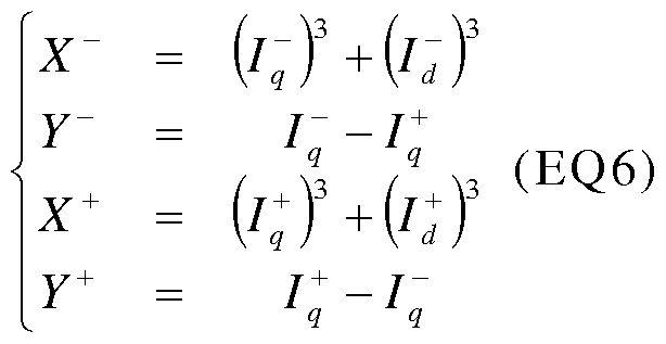
- U x and U y the new control signals applied at the input of the system, we obtain the following system of equation:
- This change of variable is implemented by deriving the expressions of X and Y to replace the values of I q and I d or their derivatives obtained by the system of equations EQ1.
- min (3 / L s * U x ) max (3 / L S ) * U X if U x is negative, or min (3 / L S ) * U X if U x is positive.
- the minimum and maximum bounds can be determined of Rs, Ls, ⁇ ⁇ and ⁇ f .
- Step E05 can then be implemented, in which the values measured previously in steps EO 1 and EO 1 are compared to the limits obtained in step E04.
- step E06 for generating signals indicating the failure of the sensor.
- FIG. 2 shows a SYS system, for example embedded in an electric or hybrid traction motor vehicle equipped with a power unit having a permanent magnet rotor.
- the SYS system can be integrated in an electronic control unit of the vehicle or in other types of computers embedded in a vehicle.
- the vehicle may comprise other means not shown in Figure 2 but which communicates with the SYS system, for example means configured to regulate stator currents delivering control signals to the electric motor.
- the SYS system comprises means 1 configured to develop a model of the electric motor linking the control signals to the direct and quadratic components of the currents.
- the means 1 are configured to implement the described step E02 with reference to FIG. 1.
- the SYS system does not include means configured to develop a model of the electric motor. linking the control signals to the direct and quadratic components of currents, such a model having been previously elaborated.
- the means 2 are configured to implement the step E03.
- the system SYS also comprises means 3 configured to determine minimum and maximum limits for X and Y able to derive from the minimum and maximum bounds for I q and I d (step E04) and means 4 configured to compare the direct and quadratic components. measured currents and said minimum and maximum bounds for I q and Id (step E05).
- the SYS system comprises means configured to develop at least one signal if one of the measured values is outside the determined limits (step E06).
- the vehicle may also comprise measuring means 6 or sensors Id and Iq currents, and also means 7 for measuring the torque.
- the SYS system and the PR method make it possible to determine whether these sensors are working.
Abstract
Description


Claims
Priority Applications (5)
| Application Number | Priority Date | Filing Date | Title |
|---|---|---|---|
| US14/763,052 US9724996B2 (en) | 2013-05-03 | 2014-04-29 | Method of verifying the operation of a motor propulsion plant fitted to an automotive vehicle and corresponding system |
| JP2016511117A JP6407969B2 (en) | 2013-05-03 | 2014-04-29 | Method for verifying the operation of a motor propulsion plant mounted on a motor vehicle and corresponding system |
| EP14727595.2A EP2992602B1 (en) | 2013-05-03 | 2014-04-29 | Method of verifying the operation of a motor propulsion plant fitted to an automotive vehicle and corresponding system |
| CN201480022415.7A CN105144569B (en) | 2013-05-03 | 2014-04-29 | The method and corresponding system that the operation of motor propulsion plant to being assembled on motor vehicles is verified |
| KR1020157016494A KR102249406B1 (en) | 2013-05-03 | 2014-04-29 | Method of verifying the operation of a motor propulsion plant fitted to an automotive vehicle and corresponding system |
Applications Claiming Priority (2)
| Application Number | Priority Date | Filing Date | Title |
|---|---|---|---|
| FR1354080 | 2013-05-03 | ||
| FR1354080A FR3005380B1 (en) | 2013-05-03 | 2013-05-03 | METHOD FOR VERIFYING THE OPERATION OF A MOTOR POWER POWERTRAIN EQUIPPED WITH A MOTOR VEHICLE AND CORRESPONDING SYSTEM |
Publications (1)
| Publication Number | Publication Date |
|---|---|
| WO2014177802A1 true WO2014177802A1 (en) | 2014-11-06 |
Family
ID=48979969
Family Applications (1)
| Application Number | Title | Priority Date | Filing Date |
|---|---|---|---|
| PCT/FR2014/051022 WO2014177802A1 (en) | 2013-05-03 | 2014-04-29 | Method of verifying the operation of a motor propulsion plant fitted to an automotive vehicle and corresponding system |
Country Status (7)
| Country | Link |
|---|---|
| US (1) | US9724996B2 (en) |
| EP (1) | EP2992602B1 (en) |
| JP (1) | JP6407969B2 (en) |
| KR (1) | KR102249406B1 (en) |
| CN (1) | CN105144569B (en) |
| FR (1) | FR3005380B1 (en) |
| WO (1) | WO2014177802A1 (en) |
Citations (4)
| Publication number | Priority date | Publication date | Assignee | Title |
|---|---|---|---|---|
| US5047699A (en) | 1989-06-26 | 1991-09-10 | Sundstrand Corporation | VSCF start system motor current estimator |
| JP2001268980A (en) | 2000-03-21 | 2001-09-28 | Koyo Seiko Co Ltd | Motor current estimator and motor controller comprising it |
| US20020008492A1 (en) | 2000-07-18 | 2002-01-24 | Nissan Motor Co., Ltd. | Motor control apparatus with a current sensor diagnostic apparatus and a current sensor diagnostic method |
| US20130077194A1 (en) * | 2011-09-23 | 2013-03-28 | GM Global Technology Operations LLC | Protection of motor drive systems from current sensor faults |
Family Cites Families (5)
| Publication number | Priority date | Publication date | Assignee | Title |
|---|---|---|---|---|
| US6163127A (en) * | 1999-11-22 | 2000-12-19 | General Motors Corporation | System and method for controlling a position sensorless permanent magnet motor |
| CA2667025C (en) * | 2006-10-19 | 2012-05-22 | Mitsubishi Electric Corporation | Vector controller for permanent-magnet synchronous electric motor |
| JP5446411B2 (en) * | 2009-04-14 | 2014-03-19 | 株式会社ジェイテクト | Motor control device and electric power steering device |
| US8080956B2 (en) * | 2010-08-26 | 2011-12-20 | Ford Global Technologies, Llc | Electric motor torque estimation |
| CN103051279B (en) * | 2012-12-19 | 2014-12-17 | 华中科技大学 | Vector control-based prediction method for uncontrollability of electric current of induction machine |
-
2013
- 2013-05-03 FR FR1354080A patent/FR3005380B1/en not_active Expired - Fee Related
-
2014
- 2014-04-29 EP EP14727595.2A patent/EP2992602B1/en active Active
- 2014-04-29 JP JP2016511117A patent/JP6407969B2/en active Active
- 2014-04-29 WO PCT/FR2014/051022 patent/WO2014177802A1/en active Application Filing
- 2014-04-29 US US14/763,052 patent/US9724996B2/en active Active
- 2014-04-29 KR KR1020157016494A patent/KR102249406B1/en active IP Right Grant
- 2014-04-29 CN CN201480022415.7A patent/CN105144569B/en active Active
Patent Citations (4)
| Publication number | Priority date | Publication date | Assignee | Title |
|---|---|---|---|---|
| US5047699A (en) | 1989-06-26 | 1991-09-10 | Sundstrand Corporation | VSCF start system motor current estimator |
| JP2001268980A (en) | 2000-03-21 | 2001-09-28 | Koyo Seiko Co Ltd | Motor current estimator and motor controller comprising it |
| US20020008492A1 (en) | 2000-07-18 | 2002-01-24 | Nissan Motor Co., Ltd. | Motor control apparatus with a current sensor diagnostic apparatus and a current sensor diagnostic method |
| US20130077194A1 (en) * | 2011-09-23 | 2013-03-28 | GM Global Technology Operations LLC | Protection of motor drive systems from current sensor faults |
Also Published As
| Publication number | Publication date |
|---|---|
| CN105144569B (en) | 2017-12-15 |
| FR3005380A1 (en) | 2014-11-07 |
| KR102249406B1 (en) | 2021-05-07 |
| EP2992602A1 (en) | 2016-03-09 |
| KR20160008154A (en) | 2016-01-21 |
| US9724996B2 (en) | 2017-08-08 |
| CN105144569A (en) | 2015-12-09 |
| FR3005380B1 (en) | 2015-04-17 |
| JP6407969B2 (en) | 2018-10-17 |
| JP2016520279A (en) | 2016-07-11 |
| US20150352958A1 (en) | 2015-12-10 |
| EP2992602B1 (en) | 2018-09-19 |
Similar Documents
| Publication | Publication Date | Title |
|---|---|---|
| EP2246973B1 (en) | Method for determining the position of the flux vector of a motor | |
| EP2997654B1 (en) | Method of estimating the angular position of the rotor of a polyphase rotating electric machine and application to the control of a polyphase inverter for such a machine | |
| FR3062762A1 (en) | METHOD OF ESTIMATING THE ANGULAR POSITION OF A ROTOR OF AN ELECTRIC DRIVE SYSTEM | |
| EP2790957A1 (en) | Method for the contactless charging of the battery of an electric automobile | |
| WO2015071576A1 (en) | Method and system for controlling an automotive vehicle three-phase electric machine supplied via chopped voltages | |
| EP2870018B1 (en) | Method for controlling a power train and corresponding system | |
| EP3221958A1 (en) | Method for controlling a synchronous electric machine with a wound rotor | |
| US9847745B1 (en) | Simulation of a field-oriented stator voltage of a stator of an asynchronous machine steadily required during operation | |
| EP3981068A1 (en) | Method for estimating the electomagnetic torque of a synchronous electric machine | |
| EP3560095B1 (en) | Direct and quadratic inductance determination method for a electric machine, corresponding software and apparatus | |
| EP2992602B1 (en) | Method of verifying the operation of a motor propulsion plant fitted to an automotive vehicle and corresponding system | |
| FR3035755A1 (en) | METHOD FOR CONTROLLING A PERMANENT MAGNET SYNCHRONOUS ELECTRIC MACHINE FOR A MOTOR VEHICLE. | |
| EP2692055B1 (en) | System and method for controlling a multiphase electric motor while taking current oscillations into account | |
| FR3022709A1 (en) | METHOD FOR CONTROLLING THE POSITION OF A ROTOR OF ELECTRIC MACHINE | |
| JP2010004699A (en) | Controller for rotating machine, and control system for rotating machine | |
| EP3012962A1 (en) | Method for controlling a three-phase synchronous electric machine with a wound rotor | |
| EP3192164A1 (en) | System and method for controlling an electrical asynchronous machine | |
| FR3028362A1 (en) | METHOD AND SYSTEM FOR CONTROLLING A SYNCHRONOUS ELECTRIC MACHINE WITH PERMANENT MAGNETS. | |
| WO2023062167A1 (en) | Method for estimating the position and speed of the rotor of a permanent-magnet synchronous electric motor | |
| EP4331108A1 (en) | Method for determining the torque of an electric machine | |
| WO2023073317A1 (en) | Method for automatically setting an angular position sensor | |
| WO2023117402A1 (en) | Method and system for controlling an electric machine driven by an inverter provided with a plurality of switching arms | |
| EP3529889A1 (en) | Methods and devices for estimating an angular position of a rotor | |
| WO2016166444A1 (en) | Method and system for controlling an asynchronous electric machine of a power train of an electric or hybrid traction automotive vehicle | |
| EP3235117A1 (en) | Method and device for evaluating operating parameters as well as process and system for controlling a synchronous machine |
Legal Events
| Date | Code | Title | Description |
|---|---|---|---|
| WWE | Wipo information: entry into national phase |
Ref document number: 201480022415.7 Country of ref document: CN |
|
| 121 | Ep: the epo has been informed by wipo that ep was designated in this application |
Ref document number: 14727595 Country of ref document: EP Kind code of ref document: A1 |
|
| WWE | Wipo information: entry into national phase |
Ref document number: 2014727595 Country of ref document: EP |
|
| ENP | Entry into the national phase |
Ref document number: 20157016494 Country of ref document: KR Kind code of ref document: A |
|
| WWE | Wipo information: entry into national phase |
Ref document number: 14763052 Country of ref document: US |
|
| ENP | Entry into the national phase |
Ref document number: 2016511117 Country of ref document: JP Kind code of ref document: A |
|
| NENP | Non-entry into the national phase |
Ref country code: DE |