WO2014141636A1 - Display body - Google Patents
Display body Download PDFInfo
- Publication number
- WO2014141636A1 WO2014141636A1 PCT/JP2014/001223 JP2014001223W WO2014141636A1 WO 2014141636 A1 WO2014141636 A1 WO 2014141636A1 JP 2014001223 W JP2014001223 W JP 2014001223W WO 2014141636 A1 WO2014141636 A1 WO 2014141636A1
- Authority
- WO
- WIPO (PCT)
- Prior art keywords
- light
- display body
- concavo
- body according
- region
- Prior art date
Links
Images


Classifications
-
- G—PHYSICS
- G02—OPTICS
- G02B—OPTICAL ELEMENTS, SYSTEMS OR APPARATUS
- G02B5/00—Optical elements other than lenses
- G02B5/18—Diffraction gratings
- G02B5/1842—Gratings for image generation
-
- B—PERFORMING OPERATIONS; TRANSPORTING
- B42—BOOKBINDING; ALBUMS; FILES; SPECIAL PRINTED MATTER
- B42D—BOOKS; BOOK COVERS; LOOSE LEAVES; PRINTED MATTER CHARACTERISED BY IDENTIFICATION OR SECURITY FEATURES; PRINTED MATTER OF SPECIAL FORMAT OR STYLE NOT OTHERWISE PROVIDED FOR; DEVICES FOR USE THEREWITH AND NOT OTHERWISE PROVIDED FOR; MOVABLE-STRIP WRITING OR READING APPARATUS
- B42D25/00—Information-bearing cards or sheet-like structures characterised by identification or security features; Manufacture thereof
- B42D25/30—Identification or security features, e.g. for preventing forgery
- B42D25/328—Diffraction gratings; Holograms
-
- B—PERFORMING OPERATIONS; TRANSPORTING
- B42—BOOKBINDING; ALBUMS; FILES; SPECIAL PRINTED MATTER
- B42D—BOOKS; BOOK COVERS; LOOSE LEAVES; PRINTED MATTER CHARACTERISED BY IDENTIFICATION OR SECURITY FEATURES; PRINTED MATTER OF SPECIAL FORMAT OR STYLE NOT OTHERWISE PROVIDED FOR; DEVICES FOR USE THEREWITH AND NOT OTHERWISE PROVIDED FOR; MOVABLE-STRIP WRITING OR READING APPARATUS
- B42D25/00—Information-bearing cards or sheet-like structures characterised by identification or security features; Manufacture thereof
- B42D25/30—Identification or security features, e.g. for preventing forgery
- B42D25/333—Watermarks
-
- B—PERFORMING OPERATIONS; TRANSPORTING
- B42—BOOKBINDING; ALBUMS; FILES; SPECIAL PRINTED MATTER
- B42D—BOOKS; BOOK COVERS; LOOSE LEAVES; PRINTED MATTER CHARACTERISED BY IDENTIFICATION OR SECURITY FEATURES; PRINTED MATTER OF SPECIAL FORMAT OR STYLE NOT OTHERWISE PROVIDED FOR; DEVICES FOR USE THEREWITH AND NOT OTHERWISE PROVIDED FOR; MOVABLE-STRIP WRITING OR READING APPARATUS
- B42D25/00—Information-bearing cards or sheet-like structures characterised by identification or security features; Manufacture thereof
- B42D25/30—Identification or security features, e.g. for preventing forgery
- B42D25/36—Identification or security features, e.g. for preventing forgery comprising special materials
- B42D25/373—Metallic materials
-
- B—PERFORMING OPERATIONS; TRANSPORTING
- B42—BOOKBINDING; ALBUMS; FILES; SPECIAL PRINTED MATTER
- B42D—BOOKS; BOOK COVERS; LOOSE LEAVES; PRINTED MATTER CHARACTERISED BY IDENTIFICATION OR SECURITY FEATURES; PRINTED MATTER OF SPECIAL FORMAT OR STYLE NOT OTHERWISE PROVIDED FOR; DEVICES FOR USE THEREWITH AND NOT OTHERWISE PROVIDED FOR; MOVABLE-STRIP WRITING OR READING APPARATUS
- B42D25/00—Information-bearing cards or sheet-like structures characterised by identification or security features; Manufacture thereof
- B42D25/40—Manufacture
- B42D25/45—Associating two or more layers
- B42D25/465—Associating two or more layers using chemicals or adhesives
- B42D25/47—Associating two or more layers using chemicals or adhesives using adhesives
-
- G—PHYSICS
- G02—OPTICS
- G02B—OPTICAL ELEMENTS, SYSTEMS OR APPARATUS
- G02B5/00—Optical elements other than lenses
- G02B5/02—Diffusing elements; Afocal elements
- G02B5/0205—Diffusing elements; Afocal elements characterised by the diffusing properties
- G02B5/021—Diffusing elements; Afocal elements characterised by the diffusing properties the diffusion taking place at the element's surface, e.g. by means of surface roughening or microprismatic structures
-
- G—PHYSICS
- G02—OPTICS
- G02B—OPTICAL ELEMENTS, SYSTEMS OR APPARATUS
- G02B5/00—Optical elements other than lenses
- G02B5/18—Diffraction gratings
- G02B5/1814—Diffraction gratings structurally combined with one or more further optical elements, e.g. lenses, mirrors, prisms or other diffraction gratings
Definitions
- the present invention relates to a display body for preventing counterfeiting and copying such as securities such as gift certificates and official documents such as passports.
- the present invention further relates to a display body that is easy to determine with the naked eye and has a high security function and a forgery prevention function, and an information medium including the display body.
- Watermarking has long been known as a technique that allows a pattern such as a picture to be confirmed by adding light and shade depending on a change in the intensity of transmitted light when the object is observed through light.
- a display body including a diffraction grating formed by arranging a plurality of grooves As a display body having a visual effect different from that of a normal printed material, a display body including a diffraction grating formed by arranging a plurality of grooves is known. For example, an image or a three-dimensional image that changes according to the observation conditions can be displayed on the display body. Further, the spectral color shining in rainbow colors expressed by the diffraction grating cannot be expressed by a normal printing technique. Therefore, a display body including a diffraction grating is widely used for articles that require anti-counterfeiting measures.
- Patent Document 1 a proposal is made to create a pattern using a liquid material on a base material such as a colorless transparent film having a matte (rough surface) surface state.
- This liquid substance is a colorless and transparent acrylic lacquer that penetrates into a rough surface and is dried.
- a multilayer interference film is provided by laminating transparent thin films of inorganic compounds.
- an interference color shining in rainbow can be confirmed.
- the interference color is a color that changes by changing the observation angle.
- the transmitted light is observed from the side opposite to the interference film, the complementary color of the regular reflection light on the interference film side can be seen. In this way, the watermark pattern and the interference color flip-flop effect coexist.
- Patent Document 2 and Patent Document 4 a printed matter in which a pattern is printed with a line on either one of the front and back sides of a printing medium and a pattern made of an image line with a pattern to be a latent image on the other line is printed on the other side.
- a printed matter in which a pattern is printed with a line on either one of the front and back sides of a printing medium and a pattern made of an image line with a pattern to be a latent image on the other line is printed on the other side.
- Patent Document 2 and Patent Document 4 show printed matter in which a line pattern is printed on either the front or back side of a printing medium through which light is transmitted.
- the line arrangement is synchronized with the line arrangement of the one line pattern, and the same line width is perpendicular to the line arrangement of the one line.
- the pattern which has it is printed.
- Printing is performed by changing the pitch of the front and back line patterns by screen printing and aligning the front and back positions. In this way, when viewed through light, a printed matter is obtained in which the front and back patterns are combined and the latent image appears as a continuous tone image.
- Patent Document 3 proposes a printed matter using a creased paper having an uneven shape.
- the concavo-convex shape is formed by embossing a line pattern representing a pattern by partially varying the angle, or a relief pattern, or an image line configuration of either pattern.
- This creped paper is inclined with respect to the parts constituting the parts other than the concavo-convex pattern, with various lines drawn at regular intervals, using inks of colors other than the material color and colorless and transparent.
- Printed is
- Patent Document 3 there is a non-constant positional relationship between the concavo-convex shape and the printed image line having a certain interval, and a specific character or pattern that becomes a latent image only when viewed from a certain angle. The effect that can be recognized is described. At the same time, in the case of creased paper, the effect that the creased image can be easily recognized by transmitted light is described.
- Patent Document 5 describes that a pattern is displayed by arranging a plurality of diffraction gratings having different groove length directions or lattice constants (that is, groove pitches).
- the wavelength of the diffracted light reaching the observer's eyes changes.
- a relief type diffraction grating formed with a plurality of grooves is generally used.
- the relief type diffraction grating is usually obtained by duplicating from an original plate manufactured using photolithography.
- Patent Document 6 shows that a picture is displayed by a combination of a diffraction grating pattern and a light scattering pattern. According to this, not only an image that changes to a rainbow color but also an image expressed by scattering of light can be displayed.
- the display body described in Patent Document 7 does not change its color to iridescent according to changes in the position of illumination or the position of the observer. Therefore, a visual effect different from the conventional diffraction grating is realized.
- Patent Document 6 and Patent Document 7 have a visual effect that is significantly different from the iridescent color of the conventional diffraction grating pattern. Therefore, a higher anti-counterfeit effect can be expected.
- Patent Document 1 As a technique for confirming the effect by transmitting light like a watermark, the proposals of Patent Documents 1 to 4 described above have been proposed.
- Patent Document 1 a coloring effect is obtained by interference of transmitted light by simply creating a watermark pattern and adding an interference multilayer film.
- a transparent resin is dropped on a rough surface such as a general diffusion film, it can be easily imitated.
- the deposition of the multilayer film is a complicated process and requires labor and time.
- Patent Document 2 and Patent Document 4 screen printing is performed by aligning the positions of the front and back of the base material, whereby a grayscale image changed by printing is observed when transmitted light is observed.
- large facilities and costs are required to accurately align double-sided printing.
- the observed pattern is limited to a grayscale image similar to a normal watermark.
- the displays and display bodies described in Patent Documents 6 and 7 can be differentiated from the visual effects of conventional diffraction grating patterns, but are both types of reflective image display bodies.
- the reflection-type image display body is manufactured on the premise that the display is performed by the emitted light that is emitted as a reflection with respect to the incident light, and the observation with the transmitted light is not taken into consideration.
- An example of means for solving the problems of the present invention is a display body in which a structure forming layer, a light reflecting layer, and a protective layer are sequentially laminated on one surface of a transparent substrate, wherein the light reflecting layer is A layer that reflects a part of light and transmits the remaining light, wherein the structure forming layer includes a plurality of structure regions, and each of the plurality of structure regions is formed of a concavo-convex structure. is there.
- each of the plurality of structural regions is different from each other with respect to at least one selected from the group consisting of a height, a period, a width of a convex portion, and a width of a concave portion of the concavo-convex structure. It is preferable that the main wavelengths of light transmitted through each of the structural regions are different from each other. Moreover, it is preferable that the plurality of structural regions are configured to display at least one selected from different patterns, characters, and numbers as an image. Furthermore, it is preferable that the uneven structure has a wind-like vertical cross section.
- the light reflecting layer is an aluminum thin film formed by one vapor deposition method selected from the group consisting of a vacuum evaporation method and a sputtering method. Furthermore, it is preferable that the dominant wavelength of the light transmitted through the structural region is in the visible light region.
- it may further include a transparent member, and the protective layer may have adhesiveness that can be bonded to the light reflecting layer and the transparent member.
- the structure forming layer further includes a non-structure region in which the uneven structure is not formed, the transmittance of the structure region exceeds 20%, and the transmittance of the non-structure region is 20% or less. There may be.
- At least one of the plurality of structural regions may include a plurality of uneven structures having different heights.
- the concavo-convex structure is formed of two types of a concavo-convex structure having a high height and a concavo-convex structure having a low height, and the concavo-convex structure having a high height and the concavo-convex structure having a low height are alternately arranged. May be.
- the highest height of the uneven structure is 250 nm or more and 600 nm or less.
- the lowest height of the said uneven structure is 10 nm or more and 200 nm or less.
- the period of the said uneven structure is 300 nm or more and 800 nm or less.
- the plurality of structural regions may be the same with respect to the period and height of the concavo-convex structure, and may be different with respect to the width of the concave portion or the width of the convex portion of the concavo-convex structure.
- a transparent member having light scattering properties may be provided on the surface of the protective layer that is not in contact with the light reflecting layer.
- the protective layer is provided with a transparent member on the surface not in contact with the light reflecting layer, and the transparent member is configured as an uneven structure, at least a part of the transparent member has light scattering properties. You may have.
- at least a part of the transparent member may have light scattering properties by providing a further uneven structure on the surface of the transparent base material that is not in contact with the structure forming layer.
- the uneven structure may have a wind-like vertical cross section.
- the uneven structure may be configured as a diffraction grating.
- at least a part of the uneven structure may be a linear structure.
- the plurality of structural regions may be arranged in a matrix.
- the light reflecting layer is preferably an aluminum thin film formed by one vapor deposition method selected from the group consisting of a vacuum evaporation method and a sputtering method.
- it may further include a transparent member, and the protective layer may have adhesiveness that can be bonded to the light reflecting layer and the transparent member.
- the present invention it is possible to provide a display body having both a high forgery prevention effect and a high designability.
- the coloring effect of transmitted light can be realized with different shades in each structural region.
- by using a nano-order fine structure it becomes possible to make systematic forgery that copies the uneven structure difficult.
- a variety of expressions are possible by configuring the plurality of structural regions to display at least one selected from different patterns, characters, and numbers as an image.
- the dominant wavelength of the light transmitted through the structural region is in the visible light region (from 380 nm to 780 nm or less), it is possible to provide a display body that displays watermark patterns showing various colors.
- the highest height of the concavo-convex structure is 250 nm or more and 600 nm or less, the light incident on the structure region is easily absorbed. Thus, the intensity of the reflected light from the structural region is reduced, while a part of the light is observed as transmitted light even if the light reflecting layer is provided. Furthermore, since the highest height of the concavo-convex structure is not less than 10 nm and not more than 200 nm, it is possible to prevent the brightness of reflected diffracted light from being lowered, so that it is possible to express with a diffraction pattern having a high brightness even during reflection observation. By combining these transmission observation effects and reflection observation effects, it is possible to provide a higher forgery prevention effect.
- the visible light region (about 380 nm or more and 780 nm or less) that is the visible light region can be taken as the dominant wavelength of the transmitted light. It is possible to provide a display body in which the watermark pattern shown can be observed.
- each of the structure areas By providing a plurality of structure areas and arranging each of the structure areas so as to represent an image such as a picture, a character, or a number, various expressions are possible.
- transmitted light having a different main wavelength for each of the plurality of structural regions, a coloring effect of transmitted light can be realized with different shades in each structural region.
- the transmittance of the structural region is 20% or more, a display body with high visibility during transmission observation is provided.
- a structural region and a non-structural region having a transmittance of 20% or less are combined, the coloring effect of transmitted light in the structural region where the uneven structure is formed and the contrast between the non-structural region where the transmitted light is not colored A difference can be made. In this way, it becomes possible to make the coloring effect in the structural region more prominent.
- FIG. 3 is a longitudinal sectional view taken along the line III-III of the display shown in FIG.
- the longitudinal cross-sectional view which shows an example of an uneven structure typically.
- the longitudinal cross-sectional view which shows another example of an uneven structure typically.
- the schematic perspective view which shows an example at the time of observing an uneven structure from the diagonal direction.
- FIG. 15 is a longitudinal sectional view taken along line XV-XV in FIG. 14.
- FIG. 18 is a longitudinal sectional view taken along line XVIII-XVIII of the display shown in FIG.
- the structure forming layer 2 is provided on one surface of the transparent substrate 1.
- the structure forming layer 2 includes a structural region 5 in which a concavo-convex structure 4 including a plurality of concave portions and convex portions is formed, and a non-structural region 6 in which the concavo-convex structure 4 is not formed.
- the structural region 5 can be a plurality of structural regions 5.
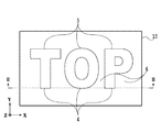
- the structure region 5 is configured to display the characters “TOP” in the concavo-convex structure 4.
- the plurality of structural regions 5 can be configured to display at least one selected from different patterns, characters, and numbers as an image.
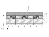
- the light reflecting layer 3, the protective layer 7, and the transparent member 8 are sequentially laminated.
- a film or sheet made of a resin having high light transmittance such as polyethylene terephthalate (PET), polycarbonate (PC), and triacetyl cellulose (TAC) is preferable.
- PET polyethylene terephthalate
- PC polycarbonate
- TAC triacetyl cellulose
- a resin having a visible light wavelength transparency can be used as the material of the structure forming layer 2.
- a resin having visible light transparency such as acrylic, polycarbonate, epoxy, polyethylene, and polypropylene can be used.
- a thermoplastic resin or a photocurable resin when used, a structure including the concavo-convex structure 4 on at least one surface of the transparent substrate 1 by transfer using an original plate on which an arbitrary concavo-convex structure 4 is formed.
- the formation layer 2 can be easily produced.
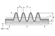
- the longitudinal section of the concavo-convex structure 4 is preferably in the form of a ripple pattern, and more preferably in a sinusoidal shape.
- FIG. 4 schematically shows an example of a longitudinal section of the concavo-convex structure 4.
- the height H of the concavo-convex structure 4 is a distance from the top of the convex portion of the concavo-convex structure 4 to the bottom side of the concave portion.
- the period P of the concavo-convex structure 4 is defined as the interval between the convex portions and the convex portions adjacent to the convex portions or the interval between the concave portions and the concave portions adjacent to the concave portions.
- the concave portion is a portion that is recessed toward the transparent substrate 1 from the center line L that divides the height H into two in the concave-convex structure 4 formed in the structural region 5.
- the convex portion is a portion that protrudes from the center line L that bisects the height H to the opposite side of the transparent substrate 1 in the concave-convex structure 4 formed in the structural region 5.
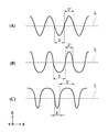
- the width of the concave portion and the width of the convex portion of the concavo-convex structure 4 will be described. That the width of the concave portion and the width of the convex portion are equal means that the width D of the concave portion and the width D ′ of the convex portion are equal as shown in FIG. 6A.
- the width D of the concave portion is different from the width of the convex portion, as shown in FIG. 6B, the width D of the concave portion is wider than the width D ′ of the convex portion, or FIG. As shown in the example, it means that the width D of the concave portion is narrower than the width D ′ of the convex portion.
- FIG. 7 shows an example of the concavo-convex structure 4 when the width D of the concave portion is wider than the width D ′ of the convex portion.
- the structure forming layer 2 is formed on the transparent substrate 1, and the uneven structure 4 is formed on the structure forming layer 2.
- the concavo-convex structure 4 having the concave portion width D and the convex portion width D ′ different from each other as shown in this example is an example of the concavo-convex structure 4 having a vertical cross section.
- the concavo-convex structure 4 in which the width D of the concave portion and the width D ′ of the convex portion are equal can be a further example of the concavo-convex structure having a wind-like or sinusoidal longitudinal section.
- the light reflecting layer 3 is a layer that reflects part of the light and transmits the remaining light.
- the light reflecting layer 3 increases the reflectance of the interface of the structure forming layer 2 provided with the concavo-convex structure 4 and contributes to the coloring effect of transmitted light.
- the light reflecting layer 3 can be formed from a transparent film or a metal film.
- the refractive index of the transparent film is preferably different from the refractive index of the light-transmitting structure forming layer 2.
- the transparent coating can be formed from a dielectric layer, a dielectric multilayer film, or a high refractive index material.
- the transparent film is preferably formed from a material selected from the group consisting of ZnS, TiO 2 , PbTiO 2 , ZrO, ZnTe, and PbCrO 4 having a refractive index of 2.0 or more.
- the difference in refractive index between the light-transmitting structure forming layer 2 and the transparent film is preferably 0.5 or more. When the difference in refractive index between the light-transmitting structure forming layer 2 and the transparent coating is less than 0.5, the visual effect of light emitted from the concavo-convex structure is weakened.
- the light reflecting layer 3 is selected from the group consisting of chromium, nickel, aluminum, iron, titanium, silver, gold, copper, and mixtures thereof, and alloys thereof. Can be formed from different materials.
- aluminum is suitable as a material of the light reflection layer 3.
- a method for producing the light reflection layer 3 using a metal material for example, it can be formed by a vapor deposition method such as a vacuum evaporation method or a sputtering method.
- the light reflecting layer 3 is preferably an aluminum thin film.
- An aluminum thin film has an advantage that it can be obtained at a lower cost than gold or silver.
- aluminum can be formed easily with high accuracy by either a vacuum evaporation method or a sputtering method.
- Aluminum also has an advantage of good handling when forming the light reflecting layer 3.
- the protective layer 7 has a purpose of protecting the concavo-convex structure 4 in order to protect the display body 10 from imitation or forgery of copying the shape of the concavo-convex structure 4.
- a thermosetting or ultraviolet curable transparent adhesive can also be used.
- it can be formed from thermoplastic resins such as polypropylene resin, polyethylene terephthalate resin, polyacetal resin, and polyester resin.
- the transparent member 8 can be further adhered and protected to the surface of the protective layer 7 that is not in contact with the light reflecting layer 3.
- the transparent member 8 a film or sheet made of a light-transmitting resin such as polyethylene terephthalate (PET), polycarbonate (PC), or triacetyl cellulose (TAC) having the same light transmission as the transparent substrate 1 is used. Is preferred. Moreover, you may use inorganic materials, such as glass.
- the transparent member 8 can also prevent imitation or forgery of copying the shape of the uneven structure 4. Further, as the transparent member 8, securities such as gift certificates, passports, package members, and the like can be assumed. In the present application, the transparent member 8 is a preferred layer.
- wavelengths other than the specific wavelength hardly interfere with the surface on the opposite side of the light source 22 because interference that cancels out at each wavefront occurs. This means that the wavelength of light transmitted to the surface opposite to the light source can be controlled by controlling the optical distance of the thin film.
- the optical distance of the structure forming layer 2 and the light reflecting layer 3 with respect to the incident light can be changed. it can. Therefore, incident light from a specific angle can be emitted as transmitted light having a specific wavelength on the surface opposite to the light source. This makes it possible to observe a color watermark pattern different from, for example, a conventional black and white watermark pattern.
- the optical distance TO changes.
- the height H of the concavo-convex structure 4 is high (large)
- the light incident on the structure region 5 is easily absorbed.
- the intensity of the reflected light from the structure region 5 decreases.
- the intensity and brightness of the reflected light are low, so that the reflected light is visually recognized as a dark gray to black area.
- the incident light is hardly absorbed. Therefore, the intensity of the reflected light from the structural region 5 increases.
- the intensity and brightness of the reflected light are high, so that the reflected light is visually recognized as a light gray to gray area.
- the structural region 5 exhibits a blue-purple to blue color when observing transmitted light from the structural region 5. This is based on the action of transmitting light having a main wavelength in a short wavelength region (about 380 nm to 480 nm).
- the structural region 5 exhibits yellow to red. This is based on the action of transmitting light having a main wavelength in the long wavelength region (about 580 nm to 680 nm).
- FIG. 5 schematically shows another example of the longitudinal section of the concavo-convex structure 4.
- the optical distance TO changes.
- the light incident on the structural region 5 is easily absorbed, so that the intensity of reflected light from the structural region 5 decreases.
- the brightness is low because the reflected light intensity is low.
- the region is visually recognized as a dark gray to black region, but the luminance is low even under the condition where the diffracted light is observed.
- the intensity of reflected light from the structure region 5 is increased because incident light is difficult to be absorbed.
- the reflected light from the structure region 5 is observed, the brightness increases because the reflected light intensity is high. Under the condition where the diffracted light is not observed, it is visually recognized as a light gray to gray region, but under the condition where the diffracted light is observed, the luminance is higher.
- the concavo-convex structure 4 when observing transmitted light, almost no transmitted light is observed by the light reflecting layer 3 in the case of the concavo-convex structure 4 having a height of 200 nm or less. On the other hand, in the concavo-convex structure 4 having a height of 250 nm to 600 nm, a part of the light is transmitted and observed even if the light reflecting layer 3 is provided.
- a plurality of concavo-convex structures 4 having different heights are provided in one structural region 5 to produce a display body that has both a high effect in transmission observation and a high effect of diffracted light in reflection observation. It becomes possible.
- the plurality of structural regions 5 are different from each other with respect to the height of the concavo-convex structure 4, it is possible to transmit light having different main wavelengths for each of the plurality of structural regions 5. This makes it possible to produce a display body that exhibits a plurality of colors when the transmitted light is observed.
- FIG. 9 is an example when the observer 21 observes the reflected light from the display body 10 of the light source 22.
- a structure such as a diffraction grating having a sinusoidal longitudinal cross section is used as the concavo-convex structure 4
- diffracted light can be observed according to the following formula (2).
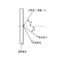
- FIG. 10 shows the positional relationship between the light incident on the diffraction grating (incident light I) and the light emitted from the diffraction grating (emitted light O).
- the period of the diffraction grating is P
- the wavelength of the incident light I is ⁇
- m is the diffraction order
- the incident angle to the structure is ⁇
- the emission angle of the m-th order diffracted light is ⁇
- diffracted light having a specific wavelength ⁇ can be observed within the range calculated by the equation (2). From the equation (2), it can be seen that the wavelength of the diffracted light changes by tilting the display body 10 or changing the observation angle. As a result, when the reflected diffracted light is observed, an effect of shining the structure region 5 in rainbow colors can be realized.
- the transmitted light from the structural region 5 of the display body 10 when the transmitted light from the structural region 5 of the display body 10 is observed, light having a specific wavelength can be observed as a watermark pattern. Further, when the reflected light from the structural region 5 of the display body 10 is observed, the diffracted light can be visually recognized within the range of characteristics, and when the display body 10 is tilted or the observation angle is changed, the diffracted light shines in rainbow colors. An effect is obtained.
- the period P of the uneven structure 4 is changed.
- the period P of the concavo-convex structure 4 provided in the structure region 5 is short, when the transmitted light from the structure region 5 is observed, it was found that the structure region 5 exhibits blue-violet to blue. This is based on the action of transmitting light having a main wavelength in a short wavelength region (about 380 nm to 480 nm).
- the period P of the concavo-convex structure 4 provided in the structure region 5 is long, it was found that the structure region 5 exhibits yellow to red color when the transmitted light from the structure region 5 is observed. This is based on the action of transmitting light having a main wavelength in the long wavelength region (about 580 nm to 680 nm). Thus, by changing the period P of the concavo-convex structure 4, the main wavelength of the light transmitted through the structural region 5 can be changed.
- the main wavelength of light transmitted through each structure region can be changed. Thereby, it is also possible to manufacture the display body 10 that exhibits a plurality of colors when the transmitted light is observed.
- the width D of the concave portion and the width D ′ of the convex portion of the uneven structure 4 are changed. It has been discovered that the main wavelength of transmitted light is shifted by changing the widths of the concave and convex portions of the concavo-convex structure 4.
- the concave and convex portions of the concavo-convex structure 4 have the same width (an example is shown in FIG. 6A)
- the dominant wavelength of light transmitted through the structural region 5 is the height H of the concavo-convex structure 4 as described above. It is arbitrarily determined according to the period P.
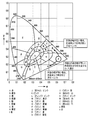
- the main wavelength of light transmitted through the structural region 5 is the case where the width of the concave portion and the convex portion of the concavo-convex structure 4 is equal. As compared with the chromaticity diagram, it shifts counterclockwise on the chromaticity diagram.
- the main wavelength of light transmitted through the structural region 5 is equal to the width of the concave portion and the convex portion of the concavo-convex structure 4. Compared to the case, it shifts in the clockwise direction on the chromaticity diagram.
- the direction of wavelength shift means the direction in which the hue on the chromaticity diagram as shown in FIG. 11 changes. As shown in FIG. 11, for example, consider a case where the main wavelength of transmitted light is red when the concave and convex portions of the concavo-convex structure 4 having a predetermined period P and height H are equal.
- the dominant wavelength of transmitted light is It shifts counterclockwise on the chromaticity diagram and becomes yellowish red to yellowish.
- the action of shifting the dominant wavelength of transmitted light can be obtained.
- the widths of the concave and convex portions of the concavo-convex structure 4 are changed, the reflection diffraction angle and the reflection diffraction wavelength hardly change. Therefore, as long as the period P is the same as long as the diffracted light or the diffracted light can be observed, light having substantially the same wavelength can be observed as reflected diffracted light.
- the period P is 300 nm to 800 nm and the height H is 100 nm to 600 nm. A light coloring effect can be expected.
- the concavo-convex structure 4 has a wind-like vertical section.
- a plurality of structural regions 5 are provided in which the period P and the height H are constant and only the widths of the concave portions or the convex portions of the concave-convex structure 4 are different.
- the reflected light when the reflected light is observed, it is visually recognized as a region exhibiting almost the same color, but it is also possible to produce the display body 10 that exhibits a different color only when the transmitted light is observed.
- Table 1 summarizes what effect occurs on reflected light and transmitted light when the period P, height H, width of the concave portion, and width of the convex portion of the concavo-convex structure fluctuate. is there.
- the wavelength of the transmitted light becomes a short wavelength region, and the reflected light becomes reflected light with increased transmitted light intensity.
- the wavelength of the transmitted light becomes a long wavelength region and the chromaticity diagram behaves so as to go around from the short wavelength region to the long wavelength region. Show. Further, the reflected light has effects such as an increase in diffraction angle and a shift of the diffraction wavelength to a short wavelength region.
- the wavelength of the transmitted light becomes a short wavelength region, and the reflected light becomes reflected light with increased transmitted light intensity.
- the wavelength of the transmitted light becomes a long wavelength region, and the chromaticity diagram shows a behavior that goes around from the short wavelength region to the long wavelength region. Further, the reflected light has effects such as a decrease in diffraction angle and a shift of the diffraction wavelength to a long wavelength region.
- the width of the concave portion is widened (the width of the convex portion is narrowed)
- the wavelength of transmitted light is shifted in the counterclockwise direction on the chromaticity diagram as compared with the case where the width of the concave portion and the width of the convex portion are equal.
- the width of the concave portion is narrowed (the width of the convex portion is widened)
- the wavelength of transmitted light shifts in the clockwise direction on the chromaticity diagram as compared with the case where the width of the concave portion and the width of the convex portion are equal.
- the main effect on the reflected light is that diffracted light is emitted according to the period P.
- the width of the concave portion and the width of the convex portion are equal, when the width of the concave portion is wide (the width of the convex portion is narrow), When the width is narrow (the width of the convex portion is wide), the diffraction angle and the diffraction wavelength are almost constant in any case.
- the display body 10 has a plurality of structure regions 5, and each of the plurality of structure regions 5 is arranged so as to display an image such as a picture, a character, a number, and the like,
- the at least one selected from the group consisting of the period, the width of the convex portion, or the width of the concave portion may be different.
- the wavelengths (colors) of transmitted light observed from the respective structural regions 5 can be made different. It is possible to observe a plurality of color images as a watermark image instead of a simple grayscale image that is the effect of a conventional watermark.
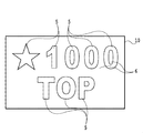
- FIG. 12 shows an example of the display body 10 having a plurality of structural regions 5.
- a picture representing a star, a number representing “1000”, and a character representing “TOP” are formed from the structural region 5.
- the region other than the structural region 5 is composed of a non-structural region 6 in which the uneven structure 4 is not formed.
- the width D of the concave portion as shown in FIG. 6B has a cross-sectional shape wider than the width D ′ of the convex portion.
- the convex portion width D ′ and the concave portion width D have the same cross-sectional shape as shown in FIG. 6A. Use structure.
- the width D of the concave portion as shown in an example in FIG. 6C has a cross-sectional shape narrower than the width D ′ of the convex portion.
- the structure is used.
- the display body 10 is manufactured such that the light transmitted through the star pattern portion is visually recognized as green, the light transmitted through the numeral “1000” is viewed as yellow, and the light transmitted through the character “TOP” is viewed as red. Is also possible.
- the light transmittance of the non-structure region 6 is 20% or less, when observing the transmitted light through the non-structure region 6, the observer can visually recognize the non-structure region 6 from gray to black. In this case, contrast with the colored transmitted light observed from the structure region 5 can be given. In this way, it is possible to more effectively use the transmitted light coloring effect in the structural region 5.
- the light transmittance of the non-structure region 6 can be controlled by the thickness of the light reflecting layer 3 formed on the surface of the structure forming layer 2 that is not in contact with the transparent substrate 1. The explanation is described below.
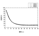
- FIG. 13 is a graph showing the thickness dependence of the transmittance at wavelengths 442 nm, 532 nm, and 633 nm when an aluminum thin film is formed on the structure forming layer 2 (refractive index 1.5).
- the transmittance at wavelengths of 442 nm, 532 nm, and 633 nm shows a value of 20% or less.
- the thickness of the aluminum thin film as the light reflecting layer 3 disposed on the non-structure region 6 is preferably 20 nm or more.
- the display body 20 shown in FIGS. 14 and 15 is formed by sequentially laminating a light transmissive structure forming layer 12, a light reflecting layer 13, an adhesive protective layer 17, and a transparent member 18 on one surface of the transparent substrate 11. It is comprised by doing.
- the structure forming layer 12 includes a plurality of structural regions 15 a and 15 b and a non-structural region 16.
- the transparent substrate 11, the light-transmitting structure forming layer 12, the light reflecting layer 13, and the protective layer 17 having adhesive properties are respectively the transparent substrate 1, the structure forming layer 2, the light reflecting layer 3, and the protective layer described above. 7 can be used.
- the structure forming layer 12 includes a plurality of structural regions 15 a and 15 b and a non-structural region 16.
- the structure forming layer 12 includes the three structural regions 15a and the three structural regions 15b.
- the number of the structural regions is not limited to six.
- the structure areas 15a and 15b are arranged in a checkered pattern, the arrangement of the structure areas is not limited to this.
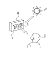
- the region in which the transmitted light 24 having the wavelength corresponding to the equation 1 can be observed depends on the size of the light source 22.
- the region where the observer 21 can observe the transmitted light 24 transmitted through the image display body 10 is only one minute point corresponding to the size of the light source 22.
- a light source 22 corresponding to the size of the image is required.
- an instrument such as a light table that can irradiate the entire image display portion of the display body 10 with incident light is required.
- the transparent member 18 has light scattering properties.
- Light incident on the transparent member 18 is scattered in the transparent member 18.
- the wavefront of the transmitted light is formed by superimposing the wavefronts of a plurality of light beams that are transmitted after the reflection is repeated an even number of times inside the display body 20.
- the point where the region where 21 can be observed does not depend on the size of the light source 22 does not occur.
- At least one of the transparent substrate 11, the structure forming layer 12, or the protective layer 17 having adhesiveness has light scattering properties. In this case as well, it is possible to observe a colored watermark image without depending on the illumination environment such as the position and size of the light source 22.
- the shape of the concavo-convex structure is made different from each other by the plurality of structural regions being different with respect to at least one selected from the group consisting of the height of the concavo-convex structure, the period, the width of the concave portion and the width of the convex portion Can do.
- each structural region is regarded as a pixel in the image, transmitted light of various colors can be emitted from each structural region. In this manner, a colorful image having a plurality of colors on the same plane can be displayed.
- the concave or convex portion of the concavo-convex structure may be a linear structure. Furthermore, a diffraction grating may be used.
- the exit angle of the diffracted light varies depending on the wavelength.
- a diffraction grating is observed under a white illumination light source such as the sun or a fluorescent lamp, white light is dispersed, and light of a single wavelength is emitted at different angles, and appears to change to a rainbow color depending on the observation angle.
- transmitted light is transmitted from the transmitted light side (protective layer side).
- transmitted light when observing, it can be observed as transmitted light of different colors, while when observing reflected light (diffracted light) from the incident light side (transparent substrate side), it can be observed as reflected light of the same color.
- the wavelength of the emitted light (diffracted light) emitted from the diffraction grating is determined by the grating constant of the diffraction grating from Equation 2 as described above. In this way, it is possible to provide a display body that can observe different images for transmission observation and reflection observation.
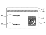
- FIG. 16 schematically shows an example of an information medium including the display body of the present invention.
- An information medium 50 shown in FIG. 16 is, for example, a magnetic card, and a printed layer 52 and a strip-shaped magnetic recording layer 53 are formed on a base material 51 on the card.
- the base material 51 is made of, for example, plastic.
- the display body 100 mentioned above is stuck to the base material 51 for anti-counterfeiting.
- the information medium 50 includes the display body 100. Therefore, forgery or imitation of this information medium 50 is difficult. Moreover, if the base material 51 is light-transmitting, a colored watermark image can be observed. Therefore, the base material 51 of the information medium 50 is preferably light transmissive.
- Example 1 17 and 18 schematically show examples of the display body of the present invention.
- the display body 10 has a polyethylene terephthalate (PET) film as the transparent substrate 1, an ultraviolet curable resin as the structure forming layer 2, and a period P and height H on the order of several hundred nm as the concavo-convex structure 4 arranged in the structure region 5.
- PET polyethylene terephthalate
- a diffraction grating is provided.
- a plurality of structure regions 5 are provided, and each concavo-convex structure 4 has a different period P and height H.
- the structure region 5 is formed of a star shape, a crescent-shaped picture or the like. Note that the structure region 5 may have an arbitrary shape. Further, as a method of forming a diffraction grating used for the concavo-convex structure 4, a laser exposure interference system may be used, or it may be formed by electron beam drawing or the like.
- the light reflecting layer 3 was formed by forming an aluminum vapor deposition layer by a vacuum vapor deposition method. At that time, vapor deposition was performed using a mask that covers the non-structural region 6 where the uneven structure 4 is not formed so that the aluminum vapor deposition layer is provided only in the structural region 5.
- thermosetting adhesive that is cured by heat was used as the protective layer 7.
- the display body 10 integrated with the transparent member 8 was obtained by bonding the transparent member 8 and the protective layer 7 together.
- a PET film having a thickness larger than that of the transparent substrate 1 was used as the transparent member 8.
- the symbols 9a and 9b were formed with printing ink in a range where the protective layer 7 of the transparent member 8 was not adhered.
- the transmitted light transmitted from the display 10 shown in FIG. 17 was observed in the positional relationship as shown in FIG.
- Light transmitted through the structural region 5 was observed in a specific color.
- the symbol 9a and the character 9b formed with the printing ink on the non-structure region 6 and the transparent member 8 were observed as black and white grayscale images. Therefore, the light transmitted through the structural region 5 was emphasized and visually recognized.
- the display body 10 shown in FIG. 17 when the display body 10 shown in FIG. 17 is observed in the positional relationship as shown in FIG. 9, the colors of the symbols 9a and the characters 9b formed on the transparent member 8 with the printing ink are visually recognized. Furthermore, diffracted light from the diffraction grating formed in the structural region 5 could be observed at a specific observation angle. When the display body 10 is tilted or the observation angle is changed, the wavelength of the diffracted light that can be observed is changed, and light shining in rainbow colors can be visually recognized.
- Example 2 A polyethylene terephthalate (PET) film was used as the transparent substrate 1. An ultraviolet curable resin was used as the transparent molding layer 2. A diffraction grating having a period P of 300 to 600 nm and a height H of 100 to 500 nm was formed as the concavo-convex structure 4 arranged in the structure region 5.
- PET polyethylene terephthalate
- H height of 100 to 500 nm
- a plurality of structures obtained by combining structure regions having different heights were provided, and the periods P were formed differently.
- the diffraction grating used for the concavo-convex structure 4 was formed by electron beam drawing.
- the light reflecting layer 3 was formed by forming an aluminum vapor deposition layer using a vacuum vapor deposition method.
- a thermosetting adhesive was used as the protective layer 7.
- a transparent member 8 was formed on the protective layer 7.
- the display member 10 integrated with the transparent member 8 was obtained by bonding the transparent member 8 and the protective layer 7 together.
- the transmitted light from the display body produced in this example was observed in a positional relationship as shown in FIG. 8 as an example, the light transmitted through the structural region 5 was observed in a specific color.
- the symbols and characters formed with the printing ink on the non-structure region 6 and the transparent member 8 were observed as black and white grayscale images. Therefore, the light transmitted through the structure region 5 was emphasized and visually recognized.
- the display body of the present example when the display body of the present example was observed in the positional relationship as shown in FIG. 9 as an example, the color of the printing ink formed on the transparent member 8 was visually recognized.
- diffracted light from the diffraction grating formed in the structure region 5 could be observed at a specific observation angle.
- the wavelength of the diffracted light that can be observed changes, and the rainbow-colored light can be visually recognized.
- the present invention is not limited to the various forms and examples described above.
- the present invention includes a display body in which any additional layers are added to the display bodies shown in various forms and examples.
- the present invention includes a display body formed by selecting each element from the display bodies shown in various forms and examples and combining them.
Abstract
Disclosed is a display body wherein a structure forming layer, a light reflecting layer, and a protection layer are sequentially laminated on one surface of a transparent base material. The light reflecting layer reflects a part of light and transmits the rest of the light, the structure forming layer includes a plurality of structure regions, and each of the structure regions is formed of a recessed and projected structure.
Description
本発明は、たとえば、商品券などの有価証券やパスポートなどの公的文書など、偽造や複写を防止するための表示体に関する。本発明は、更に、肉眼での真偽判定が容易であり、かつセキュリティ性の高い偽造防止機能を備えた表示体およびこの表示体を備えた情報媒体に関する。
The present invention relates to a display body for preventing counterfeiting and copying such as securities such as gift certificates and official documents such as passports. The present invention further relates to a display body that is easy to determine with the naked eye and has a high security function and a forgery prevention function, and an information medium including the display body.
紙幣や商品券などの有価証券、またはパスポートなどの公的文書には、偽造や模倣を防ぐ目的で、透かしと呼ばれる技術が用いられている。透かしは、対象物に光を透過させて観察した際に、透過光の強度変化によって濃淡が付くことで、絵柄などのパターンを確認することを可能にする技術として、古くから知られている。
For securities such as banknotes and gift certificates, or public documents such as passports, a technique called watermark is used for the purpose of preventing forgery and imitation. Watermarking has long been known as a technique that allows a pattern such as a picture to be confirmed by adding light and shade depending on a change in the intensity of transmitted light when the object is observed through light.
透過光の強度を変化させる方法としては、紙を製造する際に紙の厚みを僅かに変化させる、すき入れという手法などがある。現在でも、透かし技術は偽造防止手段として広く用いられている。しかしながら、油などで紙に模様を施し、一見すれば透かしと間違うような模倣をなされる危険性があり、その偽造防止効果は充分ではない。そのような中で、透かしのように対象物に光を透過させることで効果を確認できる、種々の偽造防止技術が提案されている。
As a method of changing the intensity of transmitted light, there is a technique of slightly changing the thickness of the paper when manufacturing the paper, or a method of squeezing. Even now, watermarking technology is widely used as a means for preventing forgery. However, there is a risk that the paper is patterned with oil and the like, and at first glance, there is a risk of imitation that is mistaken for a watermark, and its anti-counterfeiting effect is not sufficient. Under such circumstances, various anti-counterfeiting techniques have been proposed that can confirm the effect by transmitting light through an object like a watermark.
また、通常の印刷物とは異なる視覚効果を有している表示体としては、複数の溝を並べることにより形成された回折格子を含む表示体が知られている。この表示体には、たとえば、観察条件に応じて変化する像または立体像を表示させることができる。また、回折格子が表現する虹色に輝く分光色は、通常の印刷技術では表現することができない。そのため、回折格子を含む表示体は、偽造防止対策が必要な物品に広く用いられている。
As a display body having a visual effect different from that of a normal printed material, a display body including a diffraction grating formed by arranging a plurality of grooves is known. For example, an image or a three-dimensional image that changes according to the observation conditions can be displayed on the display body. Further, the spectral color shining in rainbow colors expressed by the diffraction grating cannot be expressed by a normal printing technique. Therefore, a display body including a diffraction grating is widely used for articles that require anti-counterfeiting measures.
特許文献1では、マット(粗面)な表面状態の無色透明フィルムなどの基材の上に、液状物質を用いて模様を作成する提案がなされている。この液状物質は、粗面に浸透して乾燥するような、無色透明のアクリルラッカーなどである。この模様部分の光透過性を他の部分の光透過性よりも増大させることで、透かし模様としている。
In Patent Document 1, a proposal is made to create a pattern using a liquid material on a base material such as a colorless transparent film having a matte (rough surface) surface state. This liquid substance is a colorless and transparent acrylic lacquer that penetrates into a rough surface and is dried. By making the light transmittance of this pattern portion greater than the light transmittance of other portions, a watermark pattern is obtained.
さらに、特許文献1では、無機化合物の透明薄膜を積層させることによって、多層干渉膜を付与している。干渉膜側から反射光を観察すると虹色に輝く干渉色が確認できる。干渉色は、観察する角度を変えることによって色が変化するものである。また、干渉膜とは反対側から透過光を観察すると干渉膜側の正反射光の補色が見える。このようにして、透かし模様と干渉色のフリップフロップ効果を共存させている。
Furthermore, in Patent Document 1, a multilayer interference film is provided by laminating transparent thin films of inorganic compounds. When the reflected light is observed from the interference film side, an interference color shining in rainbow can be confirmed. The interference color is a color that changes by changing the observation angle. Further, when the transmitted light is observed from the side opposite to the interference film, the complementary color of the regular reflection light on the interference film side can be seen. In this way, the watermark pattern and the interference color flip-flop effect coexist.
特許文献2および特許文献4では、被印刷体の表裏いずれか一方に万線によって模様を印刷し、他方には万線に潜像とすべき図柄を施した画線からなる模様を印刷した印刷物が提案されている。この印刷物を光で透かして見ることにより、表裏の模様が合成されて出現する連続階調の画像を確認することが可能となっている。
In Patent Document 2 and Patent Document 4, a printed matter in which a pattern is printed with a line on either one of the front and back sides of a printing medium and a pattern made of an image line with a pattern to be a latent image on the other line is printed on the other side. Has been proposed. By seeing this printed matter through the light, it is possible to confirm a continuous tone image that appears by combining the front and back patterns.
特許文献2および特許文献4は、光が透過する被印刷体の表裏いずれか一方に万線模様を印刷した印刷物を示している。この印刷物の、もう一方の面には、前記一方の万線模様の線配列と同期した線配列で、かつ、前記一方の万線の線配列に対して垂直方向に同程度の画線幅を有する模様を印刷されている。表裏の万線模様のピッチをスクリーン印刷によって変化させ、かつ、表裏の位置を合わせて印刷が行なわれている。こうして、光に透かして見ると表裏の模様が合成され、潜像が連続階調の像として出現する印刷物を得ている。
Patent Document 2 and Patent Document 4 show printed matter in which a line pattern is printed on either the front or back side of a printing medium through which light is transmitted. On the other side of the printed material, the line arrangement is synchronized with the line arrangement of the one line pattern, and the same line width is perpendicular to the line arrangement of the one line. The pattern which has it is printed. Printing is performed by changing the pitch of the front and back line patterns by screen printing and aligning the front and back positions. In this way, when viewed through light, a printed matter is obtained in which the front and back patterns are combined and the latent image appears as a continuous tone image.
特許文献3には、凹凸形状を有するすき入れ紙を用いた印刷物が提案されている。この凹凸形状は、部分的に角度を異なるようにすることによって図柄を表した万線模様、またはレリーフ模様、または双方の模様のいずれかの画線構成のエンボスによって形成されている。このすき入れ紙には、素材の色および無色透明以外の色のインキによって、一定な間隔を持つ各種万線画線を、凹凸形状の図柄以外の部分を構成する部分に対して、傾斜を持たせて印刷されている。
Patent Document 3 proposes a printed matter using a creased paper having an uneven shape. The concavo-convex shape is formed by embossing a line pattern representing a pattern by partially varying the angle, or a relief pattern, or an image line configuration of either pattern. This creped paper is inclined with respect to the parts constituting the parts other than the concavo-convex pattern, with various lines drawn at regular intervals, using inks of colors other than the material color and colorless and transparent. Printed.
特許文献3の印刷物では、凹凸形状と一定の間隔を持つ印刷画線との間に、一定はでない位置関係が生じ、ある特定の角度から見た時にのみ、潜像となる特定の文字、図柄などが認識できる効果が述べられている。併せて、すき入れ紙の場合は、透過光によって容易にすき入れ像が認識できる効果が述べられている。
In the printed matter of Patent Document 3, there is a non-constant positional relationship between the concavo-convex shape and the printed image line having a certain interval, and a specific character or pattern that becomes a latent image only when viewed from a certain angle. The effect that can be recognized is described. At the same time, in the case of creased paper, the effect that the creased image can be easily recognized by transmitted light is described.
特許文献5には、溝の長さ方向または格子定数(すなわち、溝のピッチ)が異なる複数の回折格子を配置して絵柄を表示することが記載されている。回折格子に対する観察者または光源の相対的な位置が変化すると、観察者の眼に到達する回折光の波長が変化する。こうして、上記の構成を採用することにより、虹色に変化する画像を表現することができる。
Patent Document 5 describes that a pattern is displayed by arranging a plurality of diffraction gratings having different groove length directions or lattice constants (that is, groove pitches). When the relative position of the observer or the light source with respect to the diffraction grating changes, the wavelength of the diffracted light reaching the observer's eyes changes. Thus, by adopting the above configuration, it is possible to express an image that changes to a rainbow color.
回折格子を利用した画像表示体では、複数の溝を形成してなるレリーフ型の回折格子を使用することが一般的である。レリーフ型回折格子は、通常、フォトリソグラフィを利用して製造した原版から複製することにより得られる。
In an image display body using a diffraction grating, a relief type diffraction grating formed with a plurality of grooves is generally used. The relief type diffraction grating is usually obtained by duplicating from an original plate manufactured using photolithography.
しかしながら、偽造防止対策が必要な物品の多くでレリーフ型回折格子を含んだ画像表示体が用いられるようになった結果、この技術が広く認知されるようになっている。それに伴い、偽造品の発生も増加する傾向にある。そのため、回折光によって虹色の光を呈することのみを特徴とした画像表示体を用いて充分な偽造防止効果を達成することが難しくなってきている。
However, as a result of the use of image display bodies including relief-type diffraction gratings in many articles that require anti-counterfeiting measures, this technology has been widely recognized. Along with this, the occurrence of counterfeit products tends to increase. For this reason, it has become difficult to achieve a sufficient anti-counterfeit effect using an image display body that is characterized only by exhibiting iridescent light by diffracted light.
特許文献6には、回折格子パターンと光散乱パターンとの組み合わせにより絵柄を表示することが示されている。これによると、虹色に変化する画像のみでなく、光の散乱で表現した画像を表示することができる。
Patent Document 6 shows that a picture is displayed by a combination of a diffraction grating pattern and a light scattering pattern. According to this, not only an image that changes to a rainbow color but also an image expressed by scattering of light can be displayed.
また、特許文献7に記載の表示体は、レリーフ型の回折格子パターンのように、照明の位置や観察者の位置の変化に応じて虹色に色変化することがない。したがって、従来の回折格子とは異なる視覚効果が実現されている。
In addition, unlike the relief-type diffraction grating pattern, the display body described in Patent Document 7 does not change its color to iridescent according to changes in the position of illumination or the position of the observer. Therefore, a visual effect different from the conventional diffraction grating is realized.
特許文献6、特許文献7に記載のディスプレイおよび表示体は、従来の回折格子パターンが有する虹色とは大きく異なる視覚効果を有する。ゆえに、より高い偽造防止効果を期待できる。
The displays and display bodies described in Patent Document 6 and Patent Document 7 have a visual effect that is significantly different from the iridescent color of the conventional diffraction grating pattern. Therefore, a higher anti-counterfeit effect can be expected.
透かしのように、光を透過させることで効果を確認できる技術として、前述した特許文献1~4などの提案がなされている。特許文献1では、簡易的に透かし模様を作製し、さらに干渉多層膜を追加することにより透過光の干渉による着色効果が得られている。しかしながら、一般的な拡散フィルムなどの粗面に透明樹脂を滴下すれば、容易に模倣され得る。また、多層膜の蒸着は複雑な工程で、手間と時間を要する。
As a technique for confirming the effect by transmitting light like a watermark, the proposals of Patent Documents 1 to 4 described above have been proposed. In Patent Document 1, a coloring effect is obtained by interference of transmitted light by simply creating a watermark pattern and adding an interference multilayer film. However, if a transparent resin is dropped on a rough surface such as a general diffusion film, it can be easily imitated. In addition, the deposition of the multilayer film is a complicated process and requires labor and time.
また、特許文献2および特許文献4では、基材の表裏に対して、位置を合わせてスクリーン印刷を行なうことで、透過光を観察した際に印刷によって変化させた濃淡画像が観察される。しかしながら、両面の印刷を正確に位置合わせするためには、大きな設備と費用を要する。また、観察される模様は、通常の透かしと似たような濃淡画像に限られている。
Further, in Patent Document 2 and Patent Document 4, screen printing is performed by aligning the positions of the front and back of the base material, whereby a grayscale image changed by printing is observed when transmitted light is observed. However, large facilities and costs are required to accurately align double-sided printing. Moreover, the observed pattern is limited to a grayscale image similar to a normal watermark.
特許文献3では、凹凸構造の傾斜した面にオフセット印刷を施しているが、基材を傾斜させて印刷を行なう必要があり、煩雑な行程を伴う。また、傾斜させた基材への印刷は、印刷位置などの制御が難しくなり、生産性に課題がある。
In Patent Document 3, offset printing is performed on the inclined surface of the concavo-convex structure, but it is necessary to perform the printing by inclining the base material, which involves a complicated process. In addition, printing on an inclined base material makes it difficult to control the printing position and the like, and there is a problem in productivity.
特許文献6、特許文献7に記載のディスプレイおよび表示体は、従来の回折格子パターンの視覚効果とは差別化できている一方で、いずれも反射型の画像表示体の一種である。反射型の画像表示体は、入射光に対して反射として射出する射出光によって表示する前提で作製されており、透過光で観察する点は考慮されていない。
The displays and display bodies described in Patent Documents 6 and 7 can be differentiated from the visual effects of conventional diffraction grating patterns, but are both types of reflective image display bodies. The reflection-type image display body is manufactured on the premise that the display is performed by the emitted light that is emitted as a reflection with respect to the incident light, and the observation with the transmitted light is not taken into consideration.
本発明が解決しようとする課題は、高い偽造防止効果および高い意匠性を併せ持つ表示体を提供することである。本発明が解決しようとする別の課題は、様々な色合いの着色効果を実現する表示体を提供することである。本発明が解決しようとする更に別の課題は、反射観察時および透過観察時の両方で特徴的な視覚効果を持つ表示体を提供することである。
The problem to be solved by the present invention is to provide a display body having a high anti-counterfeiting effect and a high designability. Another problem to be solved by the present invention is to provide a display that realizes coloring effects of various shades. Still another problem to be solved by the present invention is to provide a display body having a characteristic visual effect in both reflection observation and transmission observation.
本発明の課題を解決するための手段の一例は、透明基材の一方の面上に、構造形成層、光反射層、および保護層を順に積層した表示体であって、前記光反射層が、一部の光を反射するとともに残りの光を透過する層であり、前記構造形成層が複数の構造領域を含み、前記複数の構造領域の各々は凹凸構造から形成されている、表示体である。
An example of means for solving the problems of the present invention is a display body in which a structure forming layer, a light reflecting layer, and a protective layer are sequentially laminated on one surface of a transparent substrate, wherein the light reflecting layer is A layer that reflects a part of light and transmits the remaining light, wherein the structure forming layer includes a plurality of structure regions, and each of the plurality of structure regions is formed of a concavo-convex structure. is there.
ここで、前記複数の構造領域の各々が、その前記凹凸構造の高さ、周期、凸部の幅、および凹部の幅からなる群から選択された少なくとも1つに関して互いに異なることにより、前記複数の構造領域の各々を透過する光の主波長が互いに異なるように構成されていることが好ましい。また、前記複数の構造領域が、互いに異なる絵柄、文字、および数字から選択された少なくとも1つを画像として表示するように構成されていることが好ましい。さらに、前記凹凸構造が、風紋状の縦断面を有することが好ましい。
Here, each of the plurality of structural regions is different from each other with respect to at least one selected from the group consisting of a height, a period, a width of a convex portion, and a width of a concave portion of the concavo-convex structure. It is preferable that the main wavelengths of light transmitted through each of the structural regions are different from each other. Moreover, it is preferable that the plurality of structural regions are configured to display at least one selected from different patterns, characters, and numbers as an image. Furthermore, it is preferable that the uneven structure has a wind-like vertical cross section.
さらに、前記光反射層が、真空蒸着法およびスパッタリング法からなる群から選択された1つの気相堆積法によって成膜されたアルミニウム薄膜であることが好ましい。さらに、前記構造領域を透過する光の主波長が可視光領域にあることが好ましい。ここで、透明部材を更に含み、前記保護層が、前記光反射層および前記透明部材に接合可能な接着性を有しても良い。
Furthermore, it is preferable that the light reflecting layer is an aluminum thin film formed by one vapor deposition method selected from the group consisting of a vacuum evaporation method and a sputtering method. Furthermore, it is preferable that the dominant wavelength of the light transmitted through the structural region is in the visible light region. Here, it may further include a transparent member, and the protective layer may have adhesiveness that can be bonded to the light reflecting layer and the transparent member.
ここで、前記構造形成層が、凹凸構造が形成されていない非構造領域を更に有し、前記構造領域の透過率が20%を超えており、前記非構造領域の透過率が20%以下であっても良い。
Here, the structure forming layer further includes a non-structure region in which the uneven structure is not formed, the transmittance of the structure region exceeds 20%, and the transmittance of the non-structure region is 20% or less. There may be.
また、前記複数の構造領域の少なくとも1つが、高さの異なる複数の凹凸構造を含んでも良い。この場合、前記凹凸構造が、高さの高い凹凸構造および高さの低い凹凸構造の2種類から形成されており、前記高さの高い凹凸構造および前記高さの低い凹凸構造が交互に配置されていても良い。この場合、前記凹凸構造の最も高い高さが、250nm以上600nm以下であることが好ましい。あるいは、前記凹凸構造の最も低い高さが、10nm以上200nm以下であることが好ましい。また、前記凹凸構造の周期が、300nm以上800nm以下であることが好ましい。この場合、前記複数の構造領域が、前記凹凸構造の周期および高さに関してそれぞれ同一であり、かつ、前記凹凸構造の凹部の幅または凸部の幅に関して異なっていても良い。
In addition, at least one of the plurality of structural regions may include a plurality of uneven structures having different heights. In this case, the concavo-convex structure is formed of two types of a concavo-convex structure having a high height and a concavo-convex structure having a low height, and the concavo-convex structure having a high height and the concavo-convex structure having a low height are alternately arranged. May be. In this case, it is preferable that the highest height of the uneven structure is 250 nm or more and 600 nm or less. Or it is preferable that the lowest height of the said uneven structure is 10 nm or more and 200 nm or less. Moreover, it is preferable that the period of the said uneven structure is 300 nm or more and 800 nm or less. In this case, the plurality of structural regions may be the same with respect to the period and height of the concavo-convex structure, and may be different with respect to the width of the concave portion or the width of the convex portion of the concavo-convex structure.
さらに、前記保護層が、前記光反射層と接していない側の表面に、光散乱性を有する透明部材を設けていても良い。あるいは、前記保護層が、前記光反射層と接していない側の表面に透明部材を設け、前記透明部材が凹凸構造として構成されていることにより、前記透明部材の少なくとも一部が光散乱性を有しても良い。また、前記透明基材が、前記構造形成層と接していない側の表面に更なる凹凸構造を設けたことにより、前記透明部材の少なくとも一部が光散乱性を有しても良い。
Furthermore, a transparent member having light scattering properties may be provided on the surface of the protective layer that is not in contact with the light reflecting layer. Alternatively, when the protective layer is provided with a transparent member on the surface not in contact with the light reflecting layer, and the transparent member is configured as an uneven structure, at least a part of the transparent member has light scattering properties. You may have. Moreover, at least a part of the transparent member may have light scattering properties by providing a further uneven structure on the surface of the transparent base material that is not in contact with the structure forming layer.
ここで、前記凹凸構造が風紋状の縦断面を有しても良い。また、前記凹凸構造が回折格子として構成されていても良い。更に、前記凹凸構造の少なくとも一部が直線構造であっても良い。更に、前記複数の構造領域が、マトリクス状に配置されていても良い。前記光反射層が、真空蒸着法およびスパッタリング法からなる群から選択された1つの気相堆積法によって成膜されたアルミニウム薄膜であることが好ましい。また、前記構造領域を透過する光の主波長が可視光領域にあることが好ましい。更に、透明部材を更に含み、前記保護層が、前記光反射層および前記透明部材に接合可能な接着性を有していても良い。
Here, the uneven structure may have a wind-like vertical cross section. Further, the uneven structure may be configured as a diffraction grating. Furthermore, at least a part of the uneven structure may be a linear structure. Furthermore, the plurality of structural regions may be arranged in a matrix. The light reflecting layer is preferably an aluminum thin film formed by one vapor deposition method selected from the group consisting of a vacuum evaporation method and a sputtering method. Moreover, it is preferable that the dominant wavelength of the light which permeate | transmits the said structure area | region exists in a visible light region. Furthermore, it may further include a transparent member, and the protective layer may have adhesiveness that can be bonded to the light reflecting layer and the transparent member.
本発明によれば、高い偽造防止効果および高い意匠性を併せ持つ表示体を提供できる。例えば、各構造領域において異なる色合いで透過光の着色効果を実現できる。例えば、ナノオーダの微細な構造を用いることで、凹凸構造をコピーしてしまうような組織的な偽造を困難にさせることが可能となる。
According to the present invention, it is possible to provide a display body having both a high forgery prevention effect and a high designability. For example, the coloring effect of transmitted light can be realized with different shades in each structural region. For example, by using a nano-order fine structure, it becomes possible to make systematic forgery that copies the uneven structure difficult.
複数の構造領域が、互いに異なる絵柄、文字、および数字から選択された少なくとも1つを画像として表示するように構成することで、様々な表現が可能である。
A variety of expressions are possible by configuring the plurality of structural regions to display at least one selected from different patterns, characters, and numbers as an image.
構造領域を透過する光の主波長が可視光領域(380nm以上780nm以下程度)にあると、様々な色彩を示す透かし模様を表示する表示体を提供できる。
When the dominant wavelength of the light transmitted through the structural region is in the visible light region (from 380 nm to 780 nm or less), it is possible to provide a display body that displays watermark patterns showing various colors.
凹凸構造が形成された構造領域での透過光の着色効果と、透過光が着色しない非構造領域とのコントラスト差によって、構造領域での着色効果をより一層際立たせることも可能となる。
It is possible to make the coloring effect in the structural region more conspicuous by the difference in contrast between the coloring effect of the transmitted light in the structural region where the concavo-convex structure is formed and the non-structural region where the transmitted light is not colored.
凹凸構造の最も高い高さが250nm以上600nm以下であることで、構造領域に入射した光は吸収されやすくなる。こうして、構造領域からの反射光強度は低下する一方、光反射層を有していても一部の光が透過光として観察される。さらに、凹凸構造の最も高い高さが10nm以上200nm以下であることで、反射回折光の輝度低下が防止できるため、反射観察時にも輝度の高い回折パターンによる表現が可能となる。これらの透過観察の効果と反射観察の効果とを組み合せることにより、より高い偽造防止効果の提供が可能となる。
Since the highest height of the concavo-convex structure is 250 nm or more and 600 nm or less, the light incident on the structure region is easily absorbed. Thus, the intensity of the reflected light from the structural region is reduced, while a part of the light is observed as transmitted light even if the light reflecting layer is provided. Furthermore, since the highest height of the concavo-convex structure is not less than 10 nm and not more than 200 nm, it is possible to prevent the brightness of reflected diffracted light from being lowered, so that it is possible to express with a diffraction pattern having a high brightness even during reflection observation. By combining these transmission observation effects and reflection observation effects, it is possible to provide a higher forgery prevention effect.
また、凹凸構造の周期を300nm以上800nm以下とすることで、透過光の主波長として可視光領域である可視光領域(380nm以上780nm以下程度)の範囲をとることができるため、様々な色彩を示す透かし模様が観察できる表示体を提供することが可能となる。
In addition, by setting the period of the concavo-convex structure to 300 nm or more and 800 nm or less, the visible light region (about 380 nm or more and 780 nm or less) that is the visible light region can be taken as the dominant wavelength of the transmitted light. It is possible to provide a display body in which the watermark pattern shown can be observed.
特に、凹凸構造の高さを高い構造と低い構造の2種類とし、これらを交互に配置することで、透過観察時の色彩効果と反射観察時の輝度を両立した表示体を容易に提供することができる。
In particular, it is possible to easily provide a display body having both the color effect during transmission observation and the luminance during reflection observation by arranging the uneven structure height of two types, a high structure and a low structure, and arranging them alternately. Can do.
また、構造領域を複数設け、前記各々の構造領域を絵柄や文字、数字などの画像を表すように配置することで、様々な表現が可能となる。複数の構造領域ごとに異なる主波長の透過光を透過させることで、各構造領域において異なる色合いで透過光の着色効果を実現できる。
Further, by providing a plurality of structure areas and arranging each of the structure areas so as to represent an image such as a picture, a character, or a number, various expressions are possible. By transmitting transmitted light having a different main wavelength for each of the plurality of structural regions, a coloring effect of transmitted light can be realized with different shades in each structural region.
構造領域の透過率を20%以上とすると、透過観察時の視認性が高い表示体が提供される。また、構造領域と、透過率が20%以下となる非構造領域とを組み合わせると、凹凸構造が形成された構造領域での透過光の着色効果と、透過光が着色しない非構造領域とのコントラスト差を生じさせることができる。こうして、構造領域での着色効果をより一層際立たせることも可能となる。
When the transmittance of the structural region is 20% or more, a display body with high visibility during transmission observation is provided. In addition, when a structural region and a non-structural region having a transmittance of 20% or less are combined, the coloring effect of transmitted light in the structural region where the uneven structure is formed and the contrast between the non-structural region where the transmitted light is not colored A difference can be made. In this way, it becomes possible to make the coloring effect in the structural region more prominent.
以下、本発明の表示体を図面を参照して説明する。なお、以下に述べる種々の形態は、本発明の好適な具体例である。また、同一または類似の機能を有する部材には同一の符号を付し、その説明を省略する。
Hereinafter, the display body of the present invention will be described with reference to the drawings. Various forms described below are preferable specific examples of the present invention. Moreover, the same code | symbol is attached | subjected to the member which has the same or similar function, and the description is abbreviate | omitted.
図1~図3は、本発明の表示体の一例を概略的に示している。表示体10は、透明基材1の一方の面上に構造形成層2が設けられている。構造形成層2は、複数の凹部および凸部からなる凹凸構造4が形成された構造領域5と、凹凸構造4が形成されていない非構造領域6から構成されている。構造領域5は、複数の構造領域5とすることができる。図1において、構造領域5は、凹凸構造4で「TOP」の文字を表示するように構成されている。なお、複数の構造領域5は、互いに異なる絵柄、文字、および数字から選択された少なくとも1つを画像として表示するように構成することができる。構造形成層2の透明基材1と接していない面上には、光反射層3、保護層7、透明部材8が順に積層されている。
1 to 3 schematically show an example of the display body of the present invention. In the display body 10, the structure forming layer 2 is provided on one surface of the transparent substrate 1. The structure forming layer 2 includes a structural region 5 in which a concavo-convex structure 4 including a plurality of concave portions and convex portions is formed, and a non-structural region 6 in which the concavo-convex structure 4 is not formed. The structural region 5 can be a plurality of structural regions 5. In FIG. 1, the structure region 5 is configured to display the characters “TOP” in the concavo-convex structure 4. The plurality of structural regions 5 can be configured to display at least one selected from different patterns, characters, and numbers as an image. On the surface of the structure forming layer 2 that is not in contact with the transparent substrate 1, the light reflecting layer 3, the protective layer 7, and the transparent member 8 are sequentially laminated.
透明基材1の材料としては、ポリエチレンテレフタレート(PET)、ポリカーボネート(PC)、トリアセチルセルロース(TAC)などの光透過性が高い樹脂からなるフィルムまたはシートなどが好適である。また、ガラスなどの無機材料を使用してもよい。
As the material of the transparent substrate 1, a film or sheet made of a resin having high light transmittance such as polyethylene terephthalate (PET), polycarbonate (PC), and triacetyl cellulose (TAC) is preferable. Moreover, you may use inorganic materials, such as glass.
構造形成層2の材料としては、たとえば、可視光波長の透過性を有する樹脂を使用することができる。たとえば、アクリル、ポリカーボネート、エポキシ、ポリエチレン、ポリプロピレンなどの可視光透過性を有する樹脂を使用することができる。その中でも、たとえば、熱可塑性樹脂または光硬化性樹脂を使用すると、任意の凹凸構造4が形成された原版を用いた転写により、透明基材1の少なくとも一方の面上に凹凸構造4を備える構造形成層2を容易に作製することができる。凹凸構造4の縦断面は風紋状とすることが好ましく、正弦波形状とすることが更に好ましい。
As the material of the structure forming layer 2, for example, a resin having a visible light wavelength transparency can be used. For example, a resin having visible light transparency such as acrylic, polycarbonate, epoxy, polyethylene, and polypropylene can be used. Among them, for example, when a thermoplastic resin or a photocurable resin is used, a structure including the concavo-convex structure 4 on at least one surface of the transparent substrate 1 by transfer using an original plate on which an arbitrary concavo-convex structure 4 is formed. The formation layer 2 can be easily produced. The longitudinal section of the concavo-convex structure 4 is preferably in the form of a ripple pattern, and more preferably in a sinusoidal shape.
図4に、凹凸構造4の縦断面の一例を模式的に示す。図4において、凹凸構造4の高さHは、凹凸構造4の凸部の頂点から凹部の最底辺までの距離とする。凹凸構造4の周期Pは、凸部およびその凸部の隣の凸部の間隔または凹部およびその凹部の隣の凹部の間隔とする。凹部は、構造領域5に形成された凹凸構造4において、高さHを2等分する中心線Lから透明基材1側に窪んだ部分とする。凸部は、構造領域5に形成された凹凸構造4において、高さHを2等分する中心線Lから透明基材1とは反対側に突出した部分とする。
FIG. 4 schematically shows an example of a longitudinal section of the concavo-convex structure 4. In FIG. 4, the height H of the concavo-convex structure 4 is a distance from the top of the convex portion of the concavo-convex structure 4 to the bottom side of the concave portion. The period P of the concavo-convex structure 4 is defined as the interval between the convex portions and the convex portions adjacent to the convex portions or the interval between the concave portions and the concave portions adjacent to the concave portions. The concave portion is a portion that is recessed toward the transparent substrate 1 from the center line L that divides the height H into two in the concave-convex structure 4 formed in the structural region 5. The convex portion is a portion that protrudes from the center line L that bisects the height H to the opposite side of the transparent substrate 1 in the concave-convex structure 4 formed in the structural region 5.
次に、凹凸構造4の凹部の幅および凸部の幅を説明する。凹部の幅および凸部の幅が等しいとは、図6(A)に一例を示したように、凹部の幅Dおよび凸部の幅D′が等しいことを意味する。一方、凹部の幅および凸部の幅が異なる場合は、図6(B)に一例を示したように、凹部の幅Dが凸部の幅D′よりも広い場合、または図6(C)に一例を示したように、凹部の幅Dが凸部の幅D′よりも狭い場合を意味する。
Next, the width of the concave portion and the width of the convex portion of the concavo-convex structure 4 will be described. That the width of the concave portion and the width of the convex portion are equal means that the width D of the concave portion and the width D ′ of the convex portion are equal as shown in FIG. 6A. On the other hand, when the width of the concave portion is different from the width of the convex portion, as shown in FIG. 6B, the width D of the concave portion is wider than the width D ′ of the convex portion, or FIG. As shown in the example, it means that the width D of the concave portion is narrower than the width D ′ of the convex portion.
図7に、凹部の幅Dが凸部の幅D′よりも広い場合の凹凸構造4の一例を示す。図7では、透明基材1の上に構造形成層2が形成されており、構造形成層2に凹凸構造4が形成されている。
FIG. 7 shows an example of the concavo-convex structure 4 when the width D of the concave portion is wider than the width D ′ of the convex portion. In FIG. 7, the structure forming layer 2 is formed on the transparent substrate 1, and the uneven structure 4 is formed on the structure forming layer 2.
この例で示したような凹部の幅Dおよび凸部の幅D′が異なる凹凸構造4が、縦断面が風紋状の凹凸構造4の一例である。なお、凹部の幅Dおよび凸部の幅D′が等しい凹凸構造4は、風紋状または正弦波形状の縦断面を有する凹凸構造の更なる例とすることができる。
The concavo-convex structure 4 having the concave portion width D and the convex portion width D ′ different from each other as shown in this example is an example of the concavo-convex structure 4 having a vertical cross section. Note that the concavo-convex structure 4 in which the width D of the concave portion and the width D ′ of the convex portion are equal can be a further example of the concavo-convex structure having a wind-like or sinusoidal longitudinal section.
光反射層3は、一部の光を反射するとともに残りの光を透過する層である。光反射層3は、凹凸構造4が設けられた構造形成層2の界面の反射率を高め、透過光の着色効果に寄与する。光反射層3は、透明被膜または金属被膜から形成することができる。
The light reflecting layer 3 is a layer that reflects part of the light and transmits the remaining light. The light reflecting layer 3 increases the reflectance of the interface of the structure forming layer 2 provided with the concavo-convex structure 4 and contributes to the coloring effect of transmitted light. The light reflecting layer 3 can be formed from a transparent film or a metal film.
光反射層3が透明被膜から形成される場合、透明被膜の屈折率は、光透過性の構造形成層2の屈折率と異なる屈折率とすることが好ましい。透明被膜は、誘電体層、誘電体多層膜、もしくは高屈折率材料から形成することができる。透明被膜は、屈折率が2.0以上であるZnS、TiO2、PbTiO2、ZrO、ZnTe、およびPbCrO4からなる群から選択された材料から形成することが好ましい。光透過性の構造形成層2と透明被膜との屈折率差は0.5以上であるのが好ましい。光透過性の構造形成層2と透明被膜との屈折率差が0.5未満であると、凹凸構造からの射出光の視覚効果が弱まる。
When the light reflecting layer 3 is formed of a transparent film, the refractive index of the transparent film is preferably different from the refractive index of the light-transmitting structure forming layer 2. The transparent coating can be formed from a dielectric layer, a dielectric multilayer film, or a high refractive index material. The transparent film is preferably formed from a material selected from the group consisting of ZnS, TiO 2 , PbTiO 2 , ZrO, ZnTe, and PbCrO 4 having a refractive index of 2.0 or more. The difference in refractive index between the light-transmitting structure forming layer 2 and the transparent film is preferably 0.5 or more. When the difference in refractive index between the light-transmitting structure forming layer 2 and the transparent coating is less than 0.5, the visual effect of light emitted from the concavo-convex structure is weakened.
光反射層3が金属被膜から形成される場合、光反射層3は、クロム、ニッケル、アルミニウム、鉄、チタン、銀、金、銅、およびこれらの混合物、およびこれらの合金からなる群から選択された材料から形成することができる。なお、光反射層3の材料としては、アルミニウムが好適である。金属材料を用いて光反射層3を作製する方法としては、たとえば、真空蒸着法およびスパッタリング法などの気相堆積法により形成することができる。光反射層3はアルミニウム薄膜であることが好適である。アルミニウム薄膜は、金や銀などに比べて安価に入手できる利点がある。さらに、アルミニウムは、真空蒸着法やスパッタリング法のどちらでも精度良く容易に成膜できることが知られている。アルミニウムは、光反射層3を形成する際のハンドリングの良さも利点として有する。
When the light reflecting layer 3 is formed from a metal film, the light reflecting layer 3 is selected from the group consisting of chromium, nickel, aluminum, iron, titanium, silver, gold, copper, and mixtures thereof, and alloys thereof. Can be formed from different materials. In addition, as a material of the light reflection layer 3, aluminum is suitable. As a method for producing the light reflection layer 3 using a metal material, for example, it can be formed by a vapor deposition method such as a vacuum evaporation method or a sputtering method. The light reflecting layer 3 is preferably an aluminum thin film. An aluminum thin film has an advantage that it can be obtained at a lower cost than gold or silver. Furthermore, it is known that aluminum can be formed easily with high accuracy by either a vacuum evaporation method or a sputtering method. Aluminum also has an advantage of good handling when forming the light reflecting layer 3.
保護層7は、表示体10を凹凸構造4の形状をコピーする模倣や偽造から守るために、凹凸構造4を保護する目的を持つ。保護層7としては、熱硬化型や紫外線硬化型の透明接着剤を用いることもできる。たとえば、ポリプロピレン樹脂、ポリエチレンテレフタラート樹脂、ポリアセタール樹脂、ポリエステル樹脂等の熱可塑性樹脂等から形成することができる。この場合、保護層7の光反射層3と接していない面に、さらに透明部材8を接着し保護することも可能となる。
The protective layer 7 has a purpose of protecting the concavo-convex structure 4 in order to protect the display body 10 from imitation or forgery of copying the shape of the concavo-convex structure 4. As the protective layer 7, a thermosetting or ultraviolet curable transparent adhesive can also be used. For example, it can be formed from thermoplastic resins such as polypropylene resin, polyethylene terephthalate resin, polyacetal resin, and polyester resin. In this case, the transparent member 8 can be further adhered and protected to the surface of the protective layer 7 that is not in contact with the light reflecting layer 3.
透明部材8としては、透明基材1と同様に光透過性を有するポリエチレンテレフタレート(PET)、ポリカーボネート(PC)、トリアセチルセルロース(TAC)などの光透過性を有する樹脂からなるフィルムまたはシートなどが好適である。また、ガラスなどの無機材料を使用してもよい。透明部材8によっても、凹凸構造4の形状をコピーする模倣や偽造を防ぐことが可能となる。また、透明部材8としては商品券などの有価証券やパスポート、パッケージ部材なども想定することができる。なお、本願において透明部材8は好ましい層である。
As the transparent member 8, a film or sheet made of a light-transmitting resin such as polyethylene terephthalate (PET), polycarbonate (PC), or triacetyl cellulose (TAC) having the same light transmission as the transparent substrate 1 is used. Is preferred. Moreover, you may use inorganic materials, such as glass. The transparent member 8 can also prevent imitation or forgery of copying the shape of the uneven structure 4. Further, as the transparent member 8, securities such as gift certificates, passports, package members, and the like can be assumed. In the present application, the transparent member 8 is a preferred layer.
ここで、表示体10の視覚効果を説明する。
Here, the visual effect of the display body 10 will be described.
図8に一例を示すように、観察者21が表示体10を挟んで反対側にある光源22からの透過光を観察する場合、表示体10の構造領域5を透過した光が観察者21の目に届く。表示体10を透過する光の波面は、表示体10の内部で反射を偶数回繰り返した後に透過する光の波面を重畳することにより形成される。各波面に位相差がないときに、最大の透過光強度が得られる。その際の光学距離の差は波長の整数倍となり、下記式(1)が成立する。
mλ=2×TO×cosθ……(1)
ここで、mは回折次数であり、TOは光学的距離である。TOは、物理的な距離に加え、光が伝搬する媒質の屈折率を考慮したものである。表示体10の膜厚をD、屈折率をnとするとTO=nDが成り立つ。 As shown in FIG. 8, when theobserver 21 observes the transmitted light from the light source 22 on the opposite side across the display body 10, the light transmitted through the structural region 5 of the display body 10 Reach the eyes. The wavefront of the light that passes through the display body 10 is formed by superimposing the wavefront of the light that passes through the display body 10 after reflection is repeated an even number of times. Maximum transmitted light intensity is obtained when there is no phase difference between the wavefronts. The difference in optical distance at that time is an integral multiple of the wavelength, and the following formula (1) is established.
mλ = 2 × TO × cos θ (1)
Here, m is the diffraction order, and TO is the optical distance. TO takes into account the refractive index of the medium through which light propagates in addition to the physical distance. When the film thickness of thedisplay body 10 is D and the refractive index is n, TO = nD is established.
mλ=2×TO×cosθ……(1)
ここで、mは回折次数であり、TOは光学的距離である。TOは、物理的な距離に加え、光が伝搬する媒質の屈折率を考慮したものである。表示体10の膜厚をD、屈折率をnとするとTO=nDが成り立つ。 As shown in FIG. 8, when the
mλ = 2 × TO × cos θ (1)
Here, m is the diffraction order, and TO is the optical distance. TO takes into account the refractive index of the medium through which light propagates in addition to the physical distance. When the film thickness of the
このとき、特定の波長以外の波長は、各波面で打ち消し合う干渉を生じさせるため、光源22と反対側の面にほとんど透過しない。これは、薄膜の光学的距離を制御することで光源と反対側の面に透過する光の波長を制御可能であることを意味している。
At this time, wavelengths other than the specific wavelength hardly interfere with the surface on the opposite side of the light source 22 because interference that cancels out at each wavefront occurs. This means that the wavelength of light transmitted to the surface opposite to the light source can be controlled by controlling the optical distance of the thin film.
凹凸構造4の高さH、周期P、凹部の幅D、または凸部の幅D′を変化させることで、構造形成層2および光反射層3の入射光に対する光学的距離を変化させることができる。そのため、特定の角度からの入射光を、光源とは反対側の面に特定の波長を有する透過光として射出することが可能となる。これによって、例えば従来の白黒濃淡の透かし模様とは異なる、カラーの透かし模様を観察することが可能となる。
By changing the height H, the period P, the width D of the concave portion, or the width D ′ of the convex portion, the optical distance of the structure forming layer 2 and the light reflecting layer 3 with respect to the incident light can be changed. it can. Therefore, incident light from a specific angle can be emitted as transmitted light having a specific wavelength on the surface opposite to the light source. This makes it possible to observe a color watermark pattern different from, for example, a conventional black and white watermark pattern.
凹凸構造4の高さHを変化させる場合を説明する。構造領域5に設けられた凹凸構造4の高さHを変化させると、光学的距離TOが変化する。例えば凹凸構造4の高さHが高く(大きく)なると、構造領域5に入射した光は吸収されやすくなる。この場合、構造領域5からの反射光の強度は低下する。構造領域5からの反射光を観察する場合、反射光の強度および明度が低いため、濃い灰色から黒色を呈した領域として視認される。
The case where the height H of the uneven structure 4 is changed will be described. When the height H of the concavo-convex structure 4 provided in the structure region 5 is changed, the optical distance TO changes. For example, when the height H of the concavo-convex structure 4 is high (large), the light incident on the structure region 5 is easily absorbed. In this case, the intensity of the reflected light from the structure region 5 decreases. When the reflected light from the structure area 5 is observed, the intensity and brightness of the reflected light are low, so that the reflected light is visually recognized as a dark gray to black area.
一方、例えば凹凸構造4の高さHが低く(小さく)なると、入射した光が吸収されにくくなる。そのため、構造領域5からの反射光の強度は上昇する。構造領域5からの反射光を観察する場合、反射光の強度および明度が高いため、薄灰色から灰色を呈した領域として視認される。
On the other hand, for example, when the height H of the concavo-convex structure 4 is low (small), the incident light is hardly absorbed. Therefore, the intensity of the reflected light from the structural region 5 increases. When the reflected light from the structure area 5 is observed, the intensity and brightness of the reflected light are high, so that the reflected light is visually recognized as a light gray to gray area.
また、凹凸構造4の高さHが低いと、構造領域5からの透過光を観察する場合、構造領域5が青紫色から青色を呈することが発見された。これは、短波長領域(380nm~480nm程度)を主波長とした光が透過する作用に基づく。
It was also found that when the height H of the concavo-convex structure 4 is low, the structural region 5 exhibits a blue-purple to blue color when observing transmitted light from the structural region 5. This is based on the action of transmitting light having a main wavelength in a short wavelength region (about 380 nm to 480 nm).
さらに、凹凸構造4の高さHが高いと、構造領域5からの透過光を観察する場合、構造領域5が黄色から赤色を呈することが発見された。これは、長波長領域(580nm~680nm程度)を主波長とした光が透過する作用に基づく。
Furthermore, it was discovered that when the height H of the concavo-convex structure 4 is high, when the transmitted light from the structural region 5 is observed, the structural region 5 exhibits yellow to red. This is based on the action of transmitting light having a main wavelength in the long wavelength region (about 580 nm to 680 nm).
図5に、凹凸構造4の縦断面の別の例を模式的に示す。構造領域5に設けられた凹凸構造4の高さが変化すると、光学的距離TOが変化する。高さが250nm以上の凹凸構造4だけがある場合、構造領域5に入射した光は吸収されやすくなるため、構造領域5からの反射光強度は低下する。この場合、構造領域5からの反射光を観察すると、反射光強度が低いため明度は低くなる。回折光が観察されない条件では濃い灰色~黒色を呈した領域として視認されるが、回折光が観察される条件においてもその輝度は低いものとなる。
FIG. 5 schematically shows another example of the longitudinal section of the concavo-convex structure 4. When the height of the concavo-convex structure 4 provided in the structure region 5 changes, the optical distance TO changes. When only the concavo-convex structure 4 having a height of 250 nm or more is present, the light incident on the structural region 5 is easily absorbed, so that the intensity of reflected light from the structural region 5 decreases. In this case, when the reflected light from the structure region 5 is observed, the brightness is low because the reflected light intensity is low. Under the condition where the diffracted light is not observed, the region is visually recognized as a dark gray to black region, but the luminance is low even under the condition where the diffracted light is observed.
一方、高さHが200nm以下の凹凸構造4だけがある場合、入射した光が吸収されにくいため、構造領域5からの反射光強度は上昇する。この場合、構造領域5からの反射光を観察すると、反射光強度が高いため明度は高くなる。回折光が観察されない条件では薄灰色~灰色を呈した領域として視認されるが、回折光が観察される条件ではその輝度はより高いものとなる。
On the other hand, when only the concavo-convex structure 4 having a height H of 200 nm or less is present, the intensity of reflected light from the structure region 5 is increased because incident light is difficult to be absorbed. In this case, when the reflected light from the structure region 5 is observed, the brightness increases because the reflected light intensity is high. Under the condition where the diffracted light is not observed, it is visually recognized as a light gray to gray region, but under the condition where the diffracted light is observed, the luminance is higher.
また、透過光を観察する場合、高さが200nm以下の凹凸構造4の場合は光反射層3によりほとんど透過光が観察されない。これに対し、高さが250nm~600nmの凹凸構造4においては光反射層3を有していても一部の光が透過し観察される。
Further, when observing transmitted light, almost no transmitted light is observed by the light reflecting layer 3 in the case of the concavo-convex structure 4 having a height of 200 nm or less. On the other hand, in the concavo-convex structure 4 having a height of 250 nm to 600 nm, a part of the light is transmitted and observed even if the light reflecting layer 3 is provided.
図5に示すように、高さが異なる複数の凹凸構造4を1つの構造領域5内に設けることで、透過観察時の効果と反射観察時の回折光の効果が共に高い表示体を作製することが可能となる。
As shown in FIG. 5, a plurality of concavo-convex structures 4 having different heights are provided in one structural region 5 to produce a display body that has both a high effect in transmission observation and a high effect of diffracted light in reflection observation. It becomes possible.
更に、複数の構造領域5が凹凸構造4の高さに関して互いに異なるように構成することで、複数の構造領域5ごとに異なる主波長の光を透過するようにすることができる。これは、透過光を観察した際に、複数の色を呈する表示体を作製することを可能にする。
Furthermore, by configuring the plurality of structural regions 5 to be different from each other with respect to the height of the concavo-convex structure 4, it is possible to transmit light having different main wavelengths for each of the plurality of structural regions 5. This makes it possible to produce a display body that exhibits a plurality of colors when the transmitted light is observed.
表示体のもう1つの視覚効果として、表示体10の回折光を観察する場合の視覚効果がある。図9は、観察者21が光源22の表示体10からの反射光を観察する場合の一例である。凹凸構造4として、縦断面が正弦波形状を有する回折格子のような構造を用いている場合、下記式(2)にしたがって回折光が観察できる。
As another visual effect of the display body, there is a visual effect when diffracted light from the display body 10 is observed. FIG. 9 is an example when the observer 21 observes the reflected light from the display body 10 of the light source 22. When a structure such as a diffraction grating having a sinusoidal longitudinal cross section is used as the concavo-convex structure 4, diffracted light can be observed according to the following formula (2).
回折格子へ入射する光(入射光I)と回折格子から射出される光(射出光O)の位置関係を図10に示す。回折格子の周期をP、入射光Iの波長をλ、mを回折次数、構造への入射角度をα、m次回折光の射出角度をβとしたとき、それぞれの関係は
P(sinα-sinβ)=mλ……(2)
で計算される。 FIG. 10 shows the positional relationship between the light incident on the diffraction grating (incident light I) and the light emitted from the diffraction grating (emitted light O). When the period of the diffraction grating is P, the wavelength of the incident light I is λ, m is the diffraction order, the incident angle to the structure is α, and the emission angle of the m-th order diffracted light is β, the respective relations are P (sin α-sin β) = Mλ (2)
Calculated by
表示体10からの反射光を観察する場合、前記式(2)で計算される範囲では特定波長λの回折光を観察することができる。前記式(2)から、表示体10を傾けるかまたは観察角度を変化させることによって、回折する光の波長が変化することがわかる。この結果、反射回折光を観察すると、構造領域5が虹色に輝く効果を実現できる。
When observing the reflected light from the display body 10, diffracted light having a specific wavelength λ can be observed within the range calculated by the equation (2). From the equation (2), it can be seen that the wavelength of the diffracted light changes by tilting the display body 10 or changing the observation angle. As a result, when the reflected diffracted light is observed, an effect of shining the structure region 5 in rainbow colors can be realized.
以上のように、表示体10の構造領域5からの透過光を観察すると、特定波長の光を透かし模様として観察することができる。また、表示体10の構造領域5からの反射光を観察すると、特性の範囲では回折光を視認することができ、表示体10を傾けるかまたは観察角度を変えると、回折光が虹色に輝く効果が得られる。
As described above, when the transmitted light from the structural region 5 of the display body 10 is observed, light having a specific wavelength can be observed as a watermark pattern. Further, when the reflected light from the structural region 5 of the display body 10 is observed, the diffracted light can be visually recognized within the range of characteristics, and when the display body 10 is tilted or the observation angle is changed, the diffracted light shines in rainbow colors. An effect is obtained.
凹凸構造4の周期Pを変化させる場合を説明する。構造領域5に設けられた凹凸構造4の周期Pが短い場合、構造領域5からの透過光を観察すると、構造領域5が青紫色から青色を呈することが発見された。これは、短波長領域(380nm~480nm程度)を主波長とした光が透過する作用に基づく。
The case where the period P of the uneven structure 4 is changed will be described. When the period P of the concavo-convex structure 4 provided in the structure region 5 is short, when the transmitted light from the structure region 5 is observed, it was found that the structure region 5 exhibits blue-violet to blue. This is based on the action of transmitting light having a main wavelength in a short wavelength region (about 380 nm to 480 nm).
また、構造領域5に設けられた凹凸構造4の周期Pが長い場合、構造領域5からの透過光を観察すると、構造領域5が黄色~赤色を呈することが発見された。これは、長波長領域(580nm~680nm程度)を主波長とした光が透過する作用に基づく。このように、凹凸構造4の周期Pを変えることによって、構造領域5を透過する光の主波長を変化させることができる。
Further, when the period P of the concavo-convex structure 4 provided in the structure region 5 is long, it was found that the structure region 5 exhibits yellow to red color when the transmitted light from the structure region 5 is observed. This is based on the action of transmitting light having a main wavelength in the long wavelength region (about 580 nm to 680 nm). Thus, by changing the period P of the concavo-convex structure 4, the main wavelength of the light transmitted through the structural region 5 can be changed.
凹凸構造4の周期Pを各構造領域5で異なるものとすることで、それぞれの構造領域を透過する光の主波長を変化させることができる。これにより、透過光を観察した際に複数の色を呈する表示体10を作製することも可能となる。
By making the period P of the concavo-convex structure 4 different in each structure region 5, the main wavelength of light transmitted through each structure region can be changed. Thereby, it is also possible to manufacture the display body 10 that exhibits a plurality of colors when the transmitted light is observed.
凹凸構造4の凹部の幅Dおよび凸部の幅D’を変化させる場合を説明する。凹凸構造4の凹部および凸部の幅を変化させることで、透過光の主波長がシフトする作用が発見された。凹凸構造4の凹部および凸部の幅が等しい場合(図6(A)に一例を示す)、構造領域5を透過する光の主波長は、上記で述べたように凹凸構造4の高さHおよび周期Pに応じて任意に決定される。
The case where the width D of the concave portion and the width D ′ of the convex portion of the uneven structure 4 are changed will be described. It has been discovered that the main wavelength of transmitted light is shifted by changing the widths of the concave and convex portions of the concavo-convex structure 4. When the concave and convex portions of the concavo-convex structure 4 have the same width (an example is shown in FIG. 6A), the dominant wavelength of light transmitted through the structural region 5 is the height H of the concavo-convex structure 4 as described above. It is arbitrarily determined according to the period P.
ここで、凹凸構造4の凹部の幅を広くすると(図6(B)に一例を示す)、構造領域5を透過する光の主波長は、凹凸構造4の凹部および凸部の幅が等しい場合と比較して、色度図上において反時計回り方向へシフトする。
Here, when the width of the concave portion of the concavo-convex structure 4 is increased (an example is shown in FIG. 6B), the main wavelength of light transmitted through the structural region 5 is the case where the width of the concave portion and the convex portion of the concavo-convex structure 4 is equal. As compared with the chromaticity diagram, it shifts counterclockwise on the chromaticity diagram.
これに対し、凹凸構造4の凹部の幅を狭くすると(図6(C)に一例を示す)、構造領域5を透過する光の主波長は、凹凸構造4の凹部および凸部の幅が等しい場合と比較して、色度図上において時計回り方向へシフトする。
On the other hand, when the width of the concave portion of the concavo-convex structure 4 is reduced (an example is shown in FIG. 6C), the main wavelength of light transmitted through the structural region 5 is equal to the width of the concave portion and the convex portion of the concavo-convex structure 4. Compared to the case, it shifts in the clockwise direction on the chromaticity diagram.
上記波長のシフトの方向は、図11に示したような色度図上での色合いが変化する方向を意味する。図11に示したように、たとえば、所定の周期Pおよび高さHを持つ凹凸構造4の凹部および凸部の幅が等しいとき、透過光の主波長が赤色を呈するような場合を考える。
The direction of wavelength shift means the direction in which the hue on the chromaticity diagram as shown in FIG. 11 changes. As shown in FIG. 11, for example, consider a case where the main wavelength of transmitted light is red when the concave and convex portions of the concavo-convex structure 4 having a predetermined period P and height H are equal.
ここで、前記所定の周期Pおよび高さHを持つ凹凸構造4の凹部の幅を広くし、凸部の幅を狭くすると(図6(B)に一例を示す)、透過光の主波長は色度図上で反時計回り方向へシフトし、黄赤から黄色を呈するようになる。
Here, when the width of the concave portion of the concavo-convex structure 4 having the predetermined period P and height H is increased and the width of the convex portion is reduced (an example is shown in FIG. 6B), the dominant wavelength of transmitted light is It shifts counterclockwise on the chromaticity diagram and becomes yellowish red to yellowish.
これに対し、前記所定の周期Pおよび高さHを持つ凹凸構造4の凹部の幅を狭くし、凸部の幅を広くすると(図6(C)に一例を示す)、透過光の主波長は色度図上で時計回り方向へシフトし、赤紫から紫色を呈するようになる。
On the other hand, when the width of the concave portion of the concavo-convex structure 4 having the predetermined period P and height H is reduced and the width of the convex portion is increased (an example is shown in FIG. 6C), the dominant wavelength of transmitted light Shifts clockwise on the chromaticity diagram, becoming reddish purple to purple.
以上のように、凹凸構造4の凹部および凸部の幅を変化させることで、透過光の主波長がシフトする作用が得られる。ここで、凹凸構造4の凹部および凸部の幅を変化させても、反射回折角度および反射回折波長はほとんど変化しない。そのため、回折光または回折光が観察できる範囲では、周期Pが同じであれば、ほぼ同じ波長の光を反射回折光として観察することができる。
As described above, by changing the widths of the concave and convex portions of the concavo-convex structure 4, the action of shifting the dominant wavelength of transmitted light can be obtained. Here, even if the widths of the concave and convex portions of the concavo-convex structure 4 are changed, the reflection diffraction angle and the reflection diffraction wavelength hardly change. Therefore, as long as the period P is the same as long as the diffracted light or the diffracted light can be observed, light having substantially the same wavelength can be observed as reflected diffracted light.
凹部の幅および凸部の幅の間の関係がいずれの場合であっても、その周期Pが300nm以上800nm以下であり、およびその高さHが100nm以上600nm以下であるとすることで、透過光の着色効果が期待できる。このとき、凹凸構造4が風紋状の縦断面を有することが好ましい。
Regardless of the relationship between the width of the concave portion and the width of the convex portion, the period P is 300 nm to 800 nm and the height H is 100 nm to 600 nm. A light coloring effect can be expected. At this time, it is preferable that the concavo-convex structure 4 has a wind-like vertical section.
例えば、周期Pおよび高さHを一定とし、凹凸構造4の凹部の幅または凸部の幅のみが異なる複数の構造領域5を設ける。この場合、反射光を観察した場合にはほぼ同じ色合いを呈した領域として視認されるが、透過光を観察した場合のみ異なる色合いを呈する表示体10を作製することも可能となる。
For example, a plurality of structural regions 5 are provided in which the period P and the height H are constant and only the widths of the concave portions or the convex portions of the concave-convex structure 4 are different. In this case, when the reflected light is observed, it is visually recognized as a region exhibiting almost the same color, but it is also possible to produce the display body 10 that exhibits a different color only when the transmitted light is observed.
下記表1は、凹凸構造の周期P、高さH、凹部の幅、および凸部の幅が変動した際に、反射光および透過光に対してどのような作用が起こるのかをまとめたものである。
Table 1 below summarizes what effect occurs on reflected light and transmitted light when the period P, height H, width of the concave portion, and width of the convex portion of the concavo-convex structure fluctuate. is there.

高さHを低く(小さく)すると(例えば100nm程度)、透過光の波長は短波長領域となり、反射光は透過光強度が増加した反射光となる。
When the height H is lowered (decreased) (for example, about 100 nm), the wavelength of the transmitted light becomes a short wavelength region, and the reflected light becomes reflected light with increased transmitted light intensity.
一方、高さHを高く(大きく)すると(例えば500nm程度)、透過光の波長は、長波長領域となり、かつ、色度図上を短波長領域から長波長領域へと一周するような挙動を示す。また、反射光は、回折角度の増加、回折波長の短波長領域へのシフトなどの作用をもたらす。
On the other hand, when the height H is increased (increased) (for example, about 500 nm), the wavelength of the transmitted light becomes a long wavelength region and the chromaticity diagram behaves so as to go around from the short wavelength region to the long wavelength region. Show. Further, the reflected light has effects such as an increase in diffraction angle and a shift of the diffraction wavelength to a short wavelength region.
周期Pを短くすると(例えば300nm程度)、透過光の波長は短波長領域となり、反射光は透過光強度が増加した反射光となる。
When the period P is shortened (for example, about 300 nm), the wavelength of the transmitted light becomes a short wavelength region, and the reflected light becomes reflected light with increased transmitted light intensity.
一方、周期Pを長くすると(例えば800nm程度)、透過光の波長は、長波長領域となり、かつ、色度図上を短波長領域から長波長領域へと一周するような挙動を示す。また、反射光は、回折角度の減少、回折波長の長波長領域へのシフトなどの作用をもたらす。
On the other hand, when the period P is lengthened (for example, about 800 nm), the wavelength of the transmitted light becomes a long wavelength region, and the chromaticity diagram shows a behavior that goes around from the short wavelength region to the long wavelength region. Further, the reflected light has effects such as a decrease in diffraction angle and a shift of the diffraction wavelength to a long wavelength region.
凹部の幅を広く(凸部の幅を狭く)すると、透過光の波長は、凹部の幅および凸部の幅が等しい場合と比較して、色度図上において反時計回り方向へシフトする。
When the width of the concave portion is widened (the width of the convex portion is narrowed), the wavelength of transmitted light is shifted in the counterclockwise direction on the chromaticity diagram as compared with the case where the width of the concave portion and the width of the convex portion are equal.
一方、凹部の幅を狭く(凸部の幅を広く)すると、透過光の波長は、凹部の幅および凸部の幅が等しい場合と比較して、色度図上において時計回り方向へシフトする。
On the other hand, when the width of the concave portion is narrowed (the width of the convex portion is widened), the wavelength of transmitted light shifts in the clockwise direction on the chromaticity diagram as compared with the case where the width of the concave portion and the width of the convex portion are equal. .
反射光への主な作用としては、周期Pに応じて回折光が射出され、凹部の幅と凸部の幅が等しい場合、凹部の幅が広い(凸部の幅が狭い)場合、凹部の幅が狭い(凸部の幅が広い)場合、いずれにおいても回折角度や回折波長はほぼ一定となる。
The main effect on the reflected light is that diffracted light is emitted according to the period P. When the width of the concave portion and the width of the convex portion are equal, when the width of the concave portion is wide (the width of the convex portion is narrow), When the width is narrow (the width of the convex portion is wide), the diffraction angle and the diffraction wavelength are almost constant in any case.
表示体10は、複数の構造領域5を有し、複数の構造領域5のそれぞれが、絵柄、文字、数字などの画像を表示するように配置されていて、それぞれの凹凸構造4の高さ、周期、凸部の幅、または凹部の幅からなる群から選択された少なくとも1つに関して異なるようにすることができる。こうして、それぞれの構造領域5から観察される透過光の波長(色合い)を異なるようにすることができる。従来の透かしの効果である単純な濃淡画像ではなく、複数のカラー画像を透かし像として観察することが可能となる。
The display body 10 has a plurality of structure regions 5, and each of the plurality of structure regions 5 is arranged so as to display an image such as a picture, a character, a number, and the like, The at least one selected from the group consisting of the period, the width of the convex portion, or the width of the concave portion may be different. In this way, the wavelengths (colors) of transmitted light observed from the respective structural regions 5 can be made different. It is possible to observe a plurality of color images as a watermark image instead of a simple grayscale image that is the effect of a conventional watermark.
図12に、複数の構造領域5を有した表示体10の一例を示す。図12に示す例では、星を表す絵柄、「1000」を表す数字、「TOP」を表す文字が、それぞれ構造領域5から形成されている。また、構造領域5以外の領域は凹凸構造4が形成されていない非構造領域6で構成されている。
FIG. 12 shows an example of the display body 10 having a plurality of structural regions 5. In the example shown in FIG. 12, a picture representing a star, a number representing “1000”, and a character representing “TOP” are formed from the structural region 5. In addition, the region other than the structural region 5 is composed of a non-structural region 6 in which the uneven structure 4 is not formed.
この例においては、絵柄、数字、文字を表示するそれぞれの構造領域5を透過する主波長を異なるものとする。たとえば、星の絵柄を構成する構造領域5に用いられる凹凸構造4として、図6(B)に一例を示したような凹部の幅Dが凸部の幅D′よりも広い断面形状を持った構造を用いる。
In this example, it is assumed that the main wavelengths transmitted through the respective structural regions 5 displaying patterns, numbers, and characters are different. For example, as the concavo-convex structure 4 used in the structure region 5 constituting a star pattern, the width D of the concave portion as shown in FIG. 6B has a cross-sectional shape wider than the width D ′ of the convex portion. Use structure.
また、数字「1000」を構成する構造領域5に用いられる凹凸構造4として、図6(A)に一例を示したような凸部の幅D′および凹部の幅Dが等しい断面形状を持った構造を用いる。
Further, as the concavo-convex structure 4 used in the structure region 5 constituting the number “1000”, the convex portion width D ′ and the concave portion width D have the same cross-sectional shape as shown in FIG. 6A. Use structure.
さらに、文字「TOP」を構成する構造領域5に用いられる凹凸構造4として、図6(C)に一例を示したような凹部の幅Dが凸部の幅D′よりも狭い断面形状を持った構造を用いる。
Further, as the concavo-convex structure 4 used in the structure region 5 constituting the character “TOP”, the width D of the concave portion as shown in an example in FIG. 6C has a cross-sectional shape narrower than the width D ′ of the convex portion. The structure is used.
これにより、たとえば星の絵柄部分を透過する光が緑色、数字「1000」を透過する光が黄色、文字「TOP」を透過する光が赤色にそれぞれ視認されるような表示体10を作製することも可能となる。
Thus, for example, the display body 10 is manufactured such that the light transmitted through the star pattern portion is visually recognized as green, the light transmitted through the numeral “1000” is viewed as yellow, and the light transmitted through the character “TOP” is viewed as red. Is also possible.
また、非構造領域6の光透過率が20%以下であれば、非構造領域6を通して透過光を観察した際に、観察者は灰色から黒色として非構造領域6を視認することができる。この場合、構造領域5から観察される着色した透過光とのコントラストを付けることができる。こうして構造領域5での透過光の着色効果をより効果的に用いることが可能となる。
Further, if the light transmittance of the non-structure region 6 is 20% or less, when observing the transmitted light through the non-structure region 6, the observer can visually recognize the non-structure region 6 from gray to black. In this case, contrast with the colored transmitted light observed from the structure region 5 can be given. In this way, it is possible to more effectively use the transmitted light coloring effect in the structural region 5.
非構造領域6の光透過率は、構造形成層2の透明基材1と接していない面に形成された光反射層3の厚みによって制御することができる。以下にその説明を述べる。
The light transmittance of the non-structure region 6 can be controlled by the thickness of the light reflecting layer 3 formed on the surface of the structure forming layer 2 that is not in contact with the transparent substrate 1. The explanation is described below.
光反射層3の材料としてアルミニウム薄膜を用いる場合を考える。図13は、構造形成層2(屈折率1.5)の上にアルミニウム薄膜が形成された場合の、波長442nm、532nm、633nmにおける透過率の厚み依存性を示すグラフである。
Consider the case where an aluminum thin film is used as the material of the light reflecting layer 3. FIG. 13 is a graph showing the thickness dependence of the transmittance at wavelengths 442 nm, 532 nm, and 633 nm when an aluminum thin film is formed on the structure forming layer 2 (refractive index 1.5).
図13を参照すると、アルミニウム薄膜の厚みが20nm以上であれば、波長442nm、532nm、633nmにおける透過率は20%以下の値を示す。前述したように、非構造領域6の光透過率が20%以下であれば、非構造領域6を通して透過光を観察した際に、観察者は灰色から黒色として非構造領域6を視認することができる。この場合、構造領域5での透過光の着色効果をより一層効果的に用いることが可能となる。そのため、非構造領域6の上に配される光反射層3としてのアルミニウム薄膜の厚みは20nm以上が好適である。
Referring to FIG. 13, when the thickness of the aluminum thin film is 20 nm or more, the transmittance at wavelengths of 442 nm, 532 nm, and 633 nm shows a value of 20% or less. As described above, if the light transmittance of the non-structure region 6 is 20% or less, when the transmitted light is observed through the non-structure region 6, the observer can visually recognize the non-structure region 6 from gray to black. it can. In this case, the coloring effect of the transmitted light in the structure region 5 can be used more effectively. Therefore, the thickness of the aluminum thin film as the light reflecting layer 3 disposed on the non-structure region 6 is preferably 20 nm or more.
図14、図15は、本発明の表示体の別の例を模式的に示す。図14、図15に示す表示体20は、透明基材11の一方の面に、光透過性の構造形成層12、光反射層13、接着性を有する保護層17、透明部材18を順に積層することにより構成されている。構造形成層12は、複数の構造領域15a,15bおよび非構造領域16を備えている。
14 and 15 schematically show another example of the display body of the present invention. The display body 20 shown in FIGS. 14 and 15 is formed by sequentially laminating a light transmissive structure forming layer 12, a light reflecting layer 13, an adhesive protective layer 17, and a transparent member 18 on one surface of the transparent substrate 11. It is comprised by doing. The structure forming layer 12 includes a plurality of structural regions 15 a and 15 b and a non-structural region 16.
透明基材11、光透過性の構造形成層12、光反射層13、および接着性を有する保護層17は、それぞれ先述の透明基材1、構造形成層2、光反射層3、および保護層7と同一の材料を用いることが出来る。
The transparent substrate 11, the light-transmitting structure forming layer 12, the light reflecting layer 13, and the protective layer 17 having adhesive properties are respectively the transparent substrate 1, the structure forming layer 2, the light reflecting layer 3, and the protective layer described above. 7 can be used.
構造形成層12は、複数の構造領域15a,15bおよび非構造領域16を備えている。なお、構造形成層12は、3つの構造領域15aおよび3つの構造領域15bを備えているが、構造領域は複数あればよく、6つに限らない。また、構造領域15a,15bは市松状に配置されているが、構造領域の配置はこれに限定されない。
The structure forming layer 12 includes a plurality of structural regions 15 a and 15 b and a non-structural region 16. The structure forming layer 12 includes the three structural regions 15a and the three structural regions 15b. However, the number of the structural regions is not limited to six. Moreover, although the structure areas 15a and 15b are arranged in a checkered pattern, the arrangement of the structure areas is not limited to this.
観察者21が図8または図9に示す状態で表示体10を観察する場合、前記式1に応じた波長の透過光24を観察できる領域は、光源22の大きさに依存してしまう。たとえば、光源22が微小な点光源である場合、観察者21が画像表示体10を透過する透過光24を観察できる領域は、光源22の大きさに応じた微小な一点のみとなる。
When the observer 21 observes the display body 10 in the state shown in FIG. 8 or FIG. 9, the region in which the transmitted light 24 having the wavelength corresponding to the equation 1 can be observed depends on the size of the light source 22. For example, when the light source 22 is a minute point light source, the region where the observer 21 can observe the transmitted light 24 transmitted through the image display body 10 is only one minute point corresponding to the size of the light source 22.
すなわち、観察者21が表示体10に表示された透過光で観察できる画像全体を観察するためには、その画像の大きさに応じた光源22が必要である。言い換えれば、適切な光源22が無ければ表示体10に表示された透過光で観察できる画像全体を同時に観察することは困難である。極端に言えば、表示体10の画像表示部全体に入射光を照射できるようなライトテーブルのような器具が必要となる。
That is, in order to observe the entire image that the observer 21 can observe with the transmitted light displayed on the display body 10, a light source 22 corresponding to the size of the image is required. In other words, it is difficult to simultaneously observe the entire image that can be observed with the transmitted light displayed on the display body 10 without the appropriate light source 22. To put it extremely, an instrument such as a light table that can irradiate the entire image display portion of the display body 10 with incident light is required.
ところで、この例においては、透明部材18の少なくとも一部が光散乱性を有している。透明部材18へ入射した光は透明部材18内で散乱を生じる。この場合、透過光の波面は、表示体20の内部で反射を偶数回繰り返した後に透過する複数の光の波面を重畳することにより形成されたものであるため、前記した問題点、すなわち観察者21が観察できる領域が光源22の大きさに依存する点が発生しない。こうして、光源の位置、大きさ等の照明環境に依存することなく、画像を表示させることが可能となる。
Incidentally, in this example, at least a part of the transparent member 18 has light scattering properties. Light incident on the transparent member 18 is scattered in the transparent member 18. In this case, the wavefront of the transmitted light is formed by superimposing the wavefronts of a plurality of light beams that are transmitted after the reflection is repeated an even number of times inside the display body 20. The point where the region where 21 can be observed does not depend on the size of the light source 22 does not occur. Thus, it is possible to display an image without depending on the illumination environment such as the position and size of the light source.
また、本発明の表示体の更に別の例においては、透明基材11または構造形成層12または接着性を有する保護層17の少なくとも1つが光散乱性を有している。この場合も同様に、光源22の位置、大きさ等の照明環境に依存することなく、色付きのある透かし画像を観察することが可能である。
Further, in still another example of the display body of the present invention, at least one of the transparent substrate 11, the structure forming layer 12, or the protective layer 17 having adhesiveness has light scattering properties. In this case as well, it is possible to observe a colored watermark image without depending on the illumination environment such as the position and size of the light source 22.
更に、複数の構造領域が、凹凸構造の高さ、周期、凹部の幅および凸部の幅からなる群から選択された少なくとも1つに関して異なることにより、凹凸構造の形状が互いに異なるようにすることができる。この場合、各構造領域を画像における画素と見なすと、種種の色の透過光を各構造領域から射出することができる。こうして、同一平面上に複数の色を有した、彩りの鮮やかな画像を表示することが可能となる。
Furthermore, the shape of the concavo-convex structure is made different from each other by the plurality of structural regions being different with respect to at least one selected from the group consisting of the height of the concavo-convex structure, the period, the width of the concave portion and the width of the convex portion Can do. In this case, when each structural region is regarded as a pixel in the image, transmitted light of various colors can be emitted from each structural region. In this manner, a colorful image having a plurality of colors on the same plane can be displayed.
なお、凹凸構造の凹部または凸部は直線状の構造であってもよい。更に言えば、回折格子であってもよい。
The concave or convex portion of the concavo-convex structure may be a linear structure. Furthermore, a diffraction grating may be used.
観察に用いる照明光が複数の波長成分を含む白色光である場合、回折光の射出角は波長によって異なる。太陽や蛍光灯などの白色照明光源下で回折格子を観察すると、白色光が分光し、単一波長の光が別々の角度に射出され、観察する角度によって虹色に変化するように見える。
When the illumination light used for observation is white light containing a plurality of wavelength components, the exit angle of the diffracted light varies depending on the wavelength. When a diffraction grating is observed under a white illumination light source such as the sun or a fluorescent lamp, white light is dispersed, and light of a single wavelength is emitted at different angles, and appears to change to a rainbow color depending on the observation angle.
この場合、たとえば、複数の構造領域において、凹凸構造の周期を互いに同一とし、かつ、凹凸構造の深さまたは高さを互いに異なるようにすれば、透過光側(保護層側)から透過光を観察する場合は異なる色の透過光として観察できる一方で、入射光側(透明基材側)から反射光(回折光)を観察する場合は同一の色の反射光として観察できる。これは、前記したように回折格子から射出される射出光(回折光)の波長は、式2より回折格子の格子定数によって決まるからである。こうして、透過観察と反射観察で異なる画像を観察できる表示体を提供することが可能となる。
In this case, for example, in a plurality of structural regions, if the period of the concavo-convex structure is the same and the depth or height of the concavo-convex structure is different from each other, transmitted light is transmitted from the transmitted light side (protective layer side). When observing, it can be observed as transmitted light of different colors, while when observing reflected light (diffracted light) from the incident light side (transparent substrate side), it can be observed as reflected light of the same color. This is because the wavelength of the emitted light (diffracted light) emitted from the diffraction grating is determined by the grating constant of the diffraction grating from Equation 2 as described above. In this way, it is possible to provide a display body that can observe different images for transmission observation and reflection observation.
図16は、本発明の表示体を含む情報媒体の一例を概略的に示す。図16に示す情報媒体50は、たとえば、磁気カードであって、カード上の基材51には印刷層52および帯状の磁気記録層53が形成されている。基材51は、たとえば、プラスチックにより形成されている。そして、基材51には、前述した表示体100が偽造防止用として貼着されている。
FIG. 16 schematically shows an example of an information medium including the display body of the present invention. An information medium 50 shown in FIG. 16 is, for example, a magnetic card, and a printed layer 52 and a strip-shaped magnetic recording layer 53 are formed on a base material 51 on the card. The base material 51 is made of, for example, plastic. And the display body 100 mentioned above is stuck to the base material 51 for anti-counterfeiting.
ここで、この情報媒体50は表示体100を含んでいる。ゆえに、この情報媒体50の偽造または模造は困難である。また、基材51が光透過性であれば、色付きのある透かし画像を観察することが可能となる。ゆえに、情報媒体50の基材51は光透過性であることが好ましい。
Here, the information medium 50 includes the display body 100. Therefore, forgery or imitation of this information medium 50 is difficult. Moreover, if the base material 51 is light-transmitting, a colored watermark image can be observed. Therefore, the base material 51 of the information medium 50 is preferably light transmissive.
[実施例1]
図17および図18は、本発明の表示体の例を概略的に示している。表示体10は、透明基材1としてポリエチレンテレフタレート(PET)フィルム、構造形成層2として紫外線硬化型樹脂、構造領域5に配された凹凸構造4として数100nmオーダの周期Pおよび高さHを持つ回折格子を具備する。複数の構造領域5が設けられていて、それぞれの凹凸構造4は異なる周期Pおよび高さHを有する。 [Example 1]
17 and 18 schematically show examples of the display body of the present invention. Thedisplay body 10 has a polyethylene terephthalate (PET) film as the transparent substrate 1, an ultraviolet curable resin as the structure forming layer 2, and a period P and height H on the order of several hundred nm as the concavo-convex structure 4 arranged in the structure region 5. A diffraction grating is provided. A plurality of structure regions 5 are provided, and each concavo-convex structure 4 has a different period P and height H.
図17および図18は、本発明の表示体の例を概略的に示している。表示体10は、透明基材1としてポリエチレンテレフタレート(PET)フィルム、構造形成層2として紫外線硬化型樹脂、構造領域5に配された凹凸構造4として数100nmオーダの周期Pおよび高さHを持つ回折格子を具備する。複数の構造領域5が設けられていて、それぞれの凹凸構造4は異なる周期Pおよび高さHを有する。 [Example 1]
17 and 18 schematically show examples of the display body of the present invention. The
構造領域5は、図17に示す例では星型、三日月の形をした絵柄等で形成されている。なお、構造領域5は任意の形状をとっていてよい。また、凹凸構造4に用いる回折格子の形成方法としては、レーザ露光干渉系を用いてもよいし、電子線描画などによって形成してもよい。
In the example shown in FIG. 17, the structure region 5 is formed of a star shape, a crescent-shaped picture or the like. Note that the structure region 5 may have an arbitrary shape. Further, as a method of forming a diffraction grating used for the concavo-convex structure 4, a laser exposure interference system may be used, or it may be formed by electron beam drawing or the like.
光反射層3は、アルミ蒸着層を真空蒸着法で製膜することにより形成された。その際、構造領域5にのみアルミ蒸着層が設けられるように、凹凸構造4が形成されていない非構造領域6をカバーするマスクを用いて蒸着を行なった。
The light reflecting layer 3 was formed by forming an aluminum vapor deposition layer by a vacuum vapor deposition method. At that time, vapor deposition was performed using a mask that covers the non-structural region 6 where the uneven structure 4 is not formed so that the aluminum vapor deposition layer is provided only in the structural region 5.
保護層7として、熱によって硬化する熱硬化型接着剤を用いた。透明部材8および保護層7を接着することにより、透明部材8と一体化した表示体10が得られた。
As the protective layer 7, a thermosetting adhesive that is cured by heat was used. The display body 10 integrated with the transparent member 8 was obtained by bonding the transparent member 8 and the protective layer 7 together.
透明部材8としては、透明基材1よりも厚みのあるPETフィルムを用いた。透明部材8の保護層7が接着されていない範囲に記号9aと文字9bを印刷インキで形成した。
As the transparent member 8, a PET film having a thickness larger than that of the transparent substrate 1 was used. The symbols 9a and 9b were formed with printing ink in a range where the protective layer 7 of the transparent member 8 was not adhered.
図8に示したような位置関係で、図17に示した表示体10から透過する透過光を観察した。構造領域5を透過してきた光が特定の色合いで観察された。このとき、非構造領域6や透明部材8に印刷インキで形成された記号9aと文字9bは白黒の濃淡画像として観察された。そのため、構造領域5を透過してきた光が強調されて視認することができた。
The transmitted light transmitted from the display 10 shown in FIG. 17 was observed in the positional relationship as shown in FIG. Light transmitted through the structural region 5 was observed in a specific color. At this time, the symbol 9a and the character 9b formed with the printing ink on the non-structure region 6 and the transparent member 8 were observed as black and white grayscale images. Therefore, the light transmitted through the structural region 5 was emphasized and visually recognized.
一方、図9に一例を示したような位置関係で、図17に示した表示体10を観察すると、透明部材8に印刷インキで形成された記号9aと文字9bの色が視認された。更に、特定の観察角度では構造領域5に形成された回折格子からの回折光が観察できた。表示体10を傾けるかまたは観察角度を変えると、観察できる回折光の波長が変化し、虹色に輝く光を視認できた。
On the other hand, when the display body 10 shown in FIG. 17 is observed in the positional relationship as shown in FIG. 9, the colors of the symbols 9a and the characters 9b formed on the transparent member 8 with the printing ink are visually recognized. Furthermore, diffracted light from the diffraction grating formed in the structural region 5 could be observed at a specific observation angle. When the display body 10 is tilted or the observation angle is changed, the wavelength of the diffracted light that can be observed is changed, and light shining in rainbow colors can be visually recognized.
[実施例2]
透明基材1としてポリエチレンテレフタレート(PET)フィルムを用いた。透明成形層2として紫外線硬化型樹脂を用いた。構造領域5に配された凹凸構造4として周期Pが300~600nm、高さHが100nm~500nmの回折格子を形成した。 [Example 2]
A polyethylene terephthalate (PET) film was used as the transparent substrate 1. An ultraviolet curable resin was used as thetransparent molding layer 2. A diffraction grating having a period P of 300 to 600 nm and a height H of 100 to 500 nm was formed as the concavo-convex structure 4 arranged in the structure region 5.
透明基材1としてポリエチレンテレフタレート(PET)フィルムを用いた。透明成形層2として紫外線硬化型樹脂を用いた。構造領域5に配された凹凸構造4として周期Pが300~600nm、高さHが100nm~500nmの回折格子を形成した。 [Example 2]
A polyethylene terephthalate (PET) film was used as the transparent substrate 1. An ultraviolet curable resin was used as the
異なる高さの構造領域を組み合わせた構造を複数設け、それぞれ周期Pを異なるように形成した。凹凸構造4に用いた回折格子は、電子線描画により形成された。光反射層3は、真空蒸着法を用いてアルミ蒸着層を形成することにより成膜した。保護層7として熱硬化型接着剤を用いた。
A plurality of structures obtained by combining structure regions having different heights were provided, and the periods P were formed differently. The diffraction grating used for the concavo-convex structure 4 was formed by electron beam drawing. The light reflecting layer 3 was formed by forming an aluminum vapor deposition layer using a vacuum vapor deposition method. A thermosetting adhesive was used as the protective layer 7.
保護層7上に透明部材8を形成した。透明部材8と保護層7を接着させることで、透明部材8と一体化させた表示体10が得られた。透明部材8としては、透明基材1よりも厚みのあるPETフィルムを用いた。また、透明部材8の保護層7が接着されていない範囲に、記号および文字を印刷インキで形成した。
A transparent member 8 was formed on the protective layer 7. The display member 10 integrated with the transparent member 8 was obtained by bonding the transparent member 8 and the protective layer 7 together. As the transparent member 8, a PET film having a thickness greater than that of the transparent substrate 1 was used. Further, symbols and characters were formed with printing ink in a range where the protective layer 7 of the transparent member 8 was not adhered.
本実施例で作製した表示体からの透過光を、図8に一例を示したような位置関係で観察すると、構造領域5を透過した光が特定の色合いで観察された。このとき、非構造領域6および透明部材8に印刷インキで形成された記号と文字は、白黒の濃淡画像として観察された。その為、構造領域5を透過してきた光が強調されて視認することができた。
When the transmitted light from the display body produced in this example was observed in a positional relationship as shown in FIG. 8 as an example, the light transmitted through the structural region 5 was observed in a specific color. At this time, the symbols and characters formed with the printing ink on the non-structure region 6 and the transparent member 8 were observed as black and white grayscale images. Therefore, the light transmitted through the structure region 5 was emphasized and visually recognized.
一方、図9に一例を示したような位置関係で本実施例の表示体を観察すると、透明部材8に形成された印刷インキの色が視認された。また、特定の観察角度では構造領域5に形成された回折格子からの回折光が観察できた。表示体を傾けるかまたは観察角度を変えると、観察できる回折光の波長が変化し、虹色に輝く光を視認できた。
On the other hand, when the display body of the present example was observed in the positional relationship as shown in FIG. 9 as an example, the color of the printing ink formed on the transparent member 8 was visually recognized. In addition, diffracted light from the diffraction grating formed in the structure region 5 could be observed at a specific observation angle. When the display body is tilted or the observation angle is changed, the wavelength of the diffracted light that can be observed changes, and the rainbow-colored light can be visually recognized.
なお、本発明は、以上に述べられた種々の形態および実施例に限定されない。本発明は、種々の形態および実施例に示された表示体に更なる任意の層を追加した表示体を含む。本発明は、種々の形態および実施例に示された表示体から各要素を選択して互いに組み合わせることにより形成された表示体を含む。
It should be noted that the present invention is not limited to the various forms and examples described above. The present invention includes a display body in which any additional layers are added to the display bodies shown in various forms and examples. The present invention includes a display body formed by selecting each element from the display bodies shown in various forms and examples and combining them.
1,11 透明基材
2,12 構造形成層
3,13 光反射層
4 凹凸構造
5,15a,15b 構造領域
6,16 非構造領域
7,17 保護層
8,18 透明部材
9a 記号
9b 文字
10,20,100 表示体
21 観察者
22 光源
50 情報媒体
51 基材
52 印刷層
53 磁気記録層 DESCRIPTION OFSYMBOLS 1,11 Transparent base material 2,12 Structure formation layer 3,13 Light reflection layer 4 Uneven structure 5,15a, 15b Structure area | region 6,16 Non-structure area | region 7,17 Protective layer 8,18 Transparent member 9a Symbol 9b Character 10, 20,100 Display body 21 Observer 22 Light source 50 Information medium 51 Base material 52 Print layer 53 Magnetic recording layer
2,12 構造形成層
3,13 光反射層
4 凹凸構造
5,15a,15b 構造領域
6,16 非構造領域
7,17 保護層
8,18 透明部材
9a 記号
9b 文字
10,20,100 表示体
21 観察者
22 光源
50 情報媒体
51 基材
52 印刷層
53 磁気記録層 DESCRIPTION OF
Claims (21)
- 透明基材の一方の面上に、構造形成層、光反射層、および保護層を順に積層した表示体であって、
前記光反射層が、一部の光を反射するとともに残りの光を透過する層であり、
前記構造形成層が複数の構造領域を含み、前記複数の構造領域の各々は凹凸構造から形成されている、表示体。 A display body in which a structure forming layer, a light reflecting layer, and a protective layer are sequentially laminated on one surface of a transparent substrate,
The light reflecting layer is a layer that reflects part of the light and transmits the remaining light;
The display body, wherein the structure forming layer includes a plurality of structure regions, and each of the plurality of structure regions is formed of an uneven structure. - 前記複数の構造領域の各々が、その前記凹凸構造の高さ、周期、凸部の幅、および凹部の幅からなる群から選択された少なくとも1つに関して互いに異なることにより、前記複数の構造領域の各々を透過する光の主波長が互いに異なるように構成されている、請求項1に記載の表示体。 Each of the plurality of structural regions is different from each other with respect to at least one selected from the group consisting of a height, a period, a width of a convex portion, and a width of a concave portion of the concavo-convex structure. The display body according to claim 1, wherein main wavelengths of light transmitted through each of the display bodies are different from each other.
- 前記複数の構造領域が、互いに異なる絵柄、文字、および数字から選択された少なくとも1つを画像として表示するように構成されている、請求項1に記載の表示体。 The display body according to claim 1, wherein the plurality of structural regions are configured to display at least one selected from different patterns, characters, and numbers as an image.
- 前記構造形成層が、凹凸構造が形成されていない非構造領域を更に有し、前記構造領域の透過率が20%を超えており、前記非構造領域の透過率が20%以下である、請求項1に記載の表示体。 The structure forming layer further includes a non-structure region in which an uneven structure is not formed, the transmittance of the structure region exceeds 20%, and the transmittance of the non-structure region is 20% or less. Item 4. The display according to Item 1.
- 前記複数の構造領域の少なくとも1つが、高さの異なる複数の凹凸構造を含む、請求項1に記載の表示体。 The display body according to claim 1, wherein at least one of the plurality of structural regions includes a plurality of uneven structures having different heights.
- 前記凹凸構造が、高さの高い凹凸構造および高さの低い凹凸構造の2種類から形成されており、前記高さの高い凹凸構造および前記高さの低い凹凸構造が交互に配置されている、請求項1に記載の表示体。 The concavo-convex structure is formed of two types of a concavo-convex structure having a high height and a concavo-convex structure having a low height, and the concavo-convex structure having a high height and the concavo-convex structure having a low height are alternately arranged. The display body according to claim 1.
- 前記凹凸構造の最も高い高さが、250nm以上600nm以下である、請求項1に記載の表示体。 The display body according to claim 1, wherein the highest height of the concavo-convex structure is 250 nm or more and 600 nm or less.
- 前記凹凸構造の最も低い高さが、10nm以上200nm以下である、請求項1に記載の表示体。 The display body according to claim 1, wherein the lowest height of the concavo-convex structure is 10 nm or more and 200 nm or less.
- 前記凹凸構造の周期が、300nm以上800nm以下である、請求項1に記載の表示体。 The display body according to claim 1, wherein a period of the concavo-convex structure is 300 nm or more and 800 nm or less.
- 前記複数の構造領域が、前記凹凸構造の周期および高さに関してそれぞれ同一であり、かつ、前記凹凸構造の凹部の幅または凸部の幅に関して異なる、請求項1に記載の表示体。 The display body according to claim 1, wherein the plurality of structural regions are the same with respect to the period and height of the concavo-convex structure, and are different with respect to the width of the concave portion or the convex portion of the concavo-convex structure.
- 前記保護層が、前記光反射層と接していない側の表面に、光散乱性を有する透明部材を設けている、請求項1に記載の表示体。 The display body according to claim 1, wherein a transparent member having light scattering properties is provided on a surface of the protective layer that is not in contact with the light reflecting layer.
- 前記保護層が、前記光反射層と接していない側の表面に透明部材を設け、前記透明部材が凹凸構造として構成されていることにより、前記透明部材の少なくとも一部が光散乱性を有する、請求項1に記載の表示体。 The protective layer is provided with a transparent member on the surface not in contact with the light reflecting layer, and the transparent member is configured as an uneven structure, so that at least a part of the transparent member has light scattering properties. The display body according to claim 1.
- 前記透明基材が、前記構造形成層と接していない側の表面に更なる凹凸構造を設けたことにより、前記透明部材の少なくとも一部が光散乱性を有する、請求項1に記載の表示体。 The display body according to claim 1, wherein at least a part of the transparent member has light scattering properties by providing a further concavo-convex structure on the surface of the transparent substrate that is not in contact with the structure forming layer. .
- 前記凹凸構造が風紋状の縦断面を有する、請求項1に記載の表示体。 The display body according to claim 1, wherein the uneven structure has a wind-like vertical cross section.
- 前記凹凸構造が回折格子として構成されている、請求項1に記載の表示体。 The display body according to claim 1, wherein the uneven structure is configured as a diffraction grating.
- 前記凹凸構造の少なくとも一部が直線構造である、請求項1に記載の表示体。 The display body according to claim 1, wherein at least a part of the uneven structure has a linear structure.
- 前記複数の構造領域が、マトリクス状に配置されている、請求項1に記載の表示体。 The display body according to claim 1, wherein the plurality of structural regions are arranged in a matrix.
- 前記光反射層が、真空蒸着法およびスパッタリング法からなる群から選択された1つの気相堆積法によって成膜されたアルミニウム薄膜である、請求項1に記載の表示体。 The display body according to claim 1, wherein the light reflecting layer is an aluminum thin film formed by one vapor deposition method selected from the group consisting of a vacuum evaporation method and a sputtering method.
- 前記構造領域を透過する光の主波長が可視光領域にある、請求項1に記載の表示体。 The display body according to claim 1, wherein a dominant wavelength of light transmitted through the structural region is in a visible light region.
- 透明部材を更に含み、前記保護層が、前記光反射層および前記透明部材に接合可能な接着性を有する、請求項1に記載の表示体。 The display body according to claim 1, further comprising a transparent member, wherein the protective layer has adhesiveness capable of being bonded to the light reflecting layer and the transparent member.
- 請求項1に記載の表示体を具備した情報媒体。 An information medium comprising the display body according to claim 1.
Priority Applications (4)
| Application Number | Priority Date | Filing Date | Title |
|---|---|---|---|
| EP18192421.8A EP3427968B2 (en) | 2013-03-12 | 2014-03-05 | Display |
| KR1020157027814A KR102219805B1 (en) | 2013-03-12 | 2014-03-05 | Display body |
| EP14763434.9A EP2974879B1 (en) | 2013-03-12 | 2014-03-05 | Display body |
| US14/851,709 US10598833B2 (en) | 2013-03-12 | 2015-09-11 | Display |
Applications Claiming Priority (6)
| Application Number | Priority Date | Filing Date | Title |
|---|---|---|---|
| JP2013049426A JP6167574B2 (en) | 2013-03-12 | 2013-03-12 | Indicator |
| JP2013-049426 | 2013-03-12 | ||
| JP2013118648 | 2013-06-05 | ||
| JP2013-118648 | 2013-06-05 | ||
| JP2013126655 | 2013-06-17 | ||
| JP2013-126655 | 2013-06-17 |
Related Child Applications (1)
| Application Number | Title | Priority Date | Filing Date |
|---|---|---|---|
| US14/851,709 Continuation US10598833B2 (en) | 2013-03-12 | 2015-09-11 | Display |
Publications (1)
| Publication Number | Publication Date |
|---|---|
| WO2014141636A1 true WO2014141636A1 (en) | 2014-09-18 |
Family
ID=51536316
Family Applications (1)
| Application Number | Title | Priority Date | Filing Date |
|---|---|---|---|
| PCT/JP2014/001223 WO2014141636A1 (en) | 2013-03-12 | 2014-03-05 | Display body |
Country Status (4)
| Country | Link |
|---|---|
| US (1) | US10598833B2 (en) |
| EP (2) | EP3427968B2 (en) |
| KR (1) | KR102219805B1 (en) |
| WO (1) | WO2014141636A1 (en) |
Cited By (4)
| Publication number | Priority date | Publication date | Assignee | Title |
|---|---|---|---|---|
| JP2017083686A (en) * | 2015-10-29 | 2017-05-18 | 凸版印刷株式会社 | Display body, transfer foil including the same, and article with display body |
| WO2017155049A1 (en) * | 2016-03-11 | 2017-09-14 | 凸版印刷株式会社 | Indicator and information printed matter |
| CN108349291A (en) * | 2015-12-01 | 2018-07-31 | 捷德货币技术有限责任公司 | Security element and data medium equipped with the Security element |
| JP2021084356A (en) * | 2019-11-28 | 2021-06-03 | 尾池工業株式会社 | Decorative film molding |
Families Citing this family (8)
| Publication number | Priority date | Publication date | Assignee | Title |
|---|---|---|---|---|
| DE102015100520A1 (en) * | 2015-01-14 | 2016-07-28 | Leonhard Kurz Stiftung & Co. Kg | Multilayer body and method for its production |
| JP6232013B2 (en) * | 2015-06-01 | 2017-11-15 | 矢崎総業株式会社 | Display device |
| KR20170031397A (en) | 2015-09-11 | 2017-03-21 | 주식회사 만도 | Electric brake system |
| DE112017000519T5 (en) * | 2016-01-27 | 2018-10-25 | Toppan Printing Co., Ltd. | LAYER, METHOD FOR MAKING A LAYER AND PERSONAL AUTHENTICATION MEDIUM |
| US11167582B2 (en) * | 2016-02-09 | 2021-11-09 | Toppan Printing Co., Ltd. | Optical element and information recording medium for counterfeit prevention |
| JP6662333B2 (en) | 2017-03-14 | 2020-03-11 | オムロン株式会社 | Display device |
| JPWO2020209331A1 (en) * | 2019-04-09 | 2020-10-15 | ||
| DE102019003214A1 (en) * | 2019-05-07 | 2020-11-12 | Giesecke+Devrient Currency Technology Gmbh | Decorative element with multilayer structure and decorative equipment |
Citations (11)
| Publication number | Priority date | Publication date | Assignee | Title |
|---|---|---|---|---|
| US5058992A (en) | 1988-09-07 | 1991-10-22 | Toppan Printing Co., Ltd. | Method for producing a display with a diffraction grating pattern and a display produced by the method |
| JPH0813568B2 (en) | 1991-11-22 | 1996-02-14 | 大蔵省印刷局長 | Laminated image front and back pattern synthetic printed material and method for producing the same |
| JP2615401B2 (en) | 1992-06-04 | 1997-05-28 | 大蔵省印刷局長 | Anti-counterfeit latent image pattern forming body and method of manufacturing the same |
| JP2751721B2 (en) | 1992-03-26 | 1998-05-18 | 凸版印刷株式会社 | Display with diffraction grating pattern |
| JP2840724B2 (en) | 1989-07-21 | 1998-12-24 | 大蔵省印刷局長 | Method for creating watermark pattern having iris color and its product |
| JP2010044267A (en) * | 2008-08-14 | 2010-02-25 | Toppan Printing Co Ltd | Display, adhesive label, transferring foil, and article with label |
| JP2010286722A (en) * | 2009-06-12 | 2010-12-24 | Toppan Printing Co Ltd | Display body and article with label |
| JP2011002491A (en) * | 2009-06-16 | 2011-01-06 | Toppan Printing Co Ltd | Display body and article with label |
| JP2011118035A (en) | 2009-12-01 | 2011-06-16 | Toppan Printing Co Ltd | Display body and labeled article |
| JP2012203141A (en) * | 2011-03-24 | 2012-10-22 | Toppan Printing Co Ltd | Display body and labeled article |
| JP2012206352A (en) * | 2011-03-29 | 2012-10-25 | Toppan Printing Co Ltd | Indicator and article with label |
Family Cites Families (33)
| Publication number | Priority date | Publication date | Assignee | Title |
|---|---|---|---|---|
| JPH02135101A (en) | 1988-11-17 | 1990-05-24 | Ebara Corp | Extractive separation using high-density fluid |
| US5856048A (en) * | 1992-07-27 | 1999-01-05 | Dai Nippon Printing Co., Ltd. | Information-recorded media and methods for reading the information |
| DE4334847A1 (en) | 1993-10-13 | 1995-04-20 | Kurz Leonhard Fa | Value document with window |
| JP2866807B2 (en) | 1994-07-02 | 1999-03-08 | 有限会社福永博建築研究所 | Piping method, body edge and pipe shaft of apartment house |
| US6582422B2 (en) * | 2001-10-03 | 2003-06-24 | Bausch & Lomb Incorporated | Ophthalmic delivery device |
| CZ20041001A3 (en) * | 2002-04-03 | 2005-03-16 | De La Rue International Limited | Optically variable protective element and process for producing thereof |
| DE10216562C1 (en) | 2002-04-05 | 2003-12-11 | Ovd Kinegram Ag Zug | Security element with micro and macro structures |
| JP4564381B2 (en) | 2004-03-10 | 2010-10-20 | 大日本印刷株式会社 | Hologram transfer foil and manufacturing method thereof |
| DE102004016596B4 (en) † | 2004-04-03 | 2006-07-27 | Ovd Kinegram Ag | Security element in the form of a multilayer film body and method for producing a security element |
| DE102004042136B4 (en) | 2004-08-30 | 2006-11-09 | Ovd Kinegram Ag | Metallized security element |
| DE102005028162A1 (en) | 2005-02-18 | 2006-12-28 | Giesecke & Devrient Gmbh | Security element for protecting valuable objects, e.g. documents, includes focusing components for enlarging views of microscopic structures as one of two authenication features |
| DE102005017169B4 (en) | 2005-04-13 | 2023-06-22 | Ovd Kinegram Ag | transfer film |
| EP2021840B2 (en) | 2006-05-02 | 2022-09-21 | Surys | Optical security marking component, method of manufacturing such a component, system comprising such a component, and reader for checking such a component |
| WO2008027561A2 (en) * | 2006-09-01 | 2008-03-06 | Cabot Corporation | Surface-treated metal oxide particles |
| JP4961944B2 (en) | 2006-10-24 | 2012-06-27 | 凸版印刷株式会社 | Display and printed matter |
| DE102007039996B4 (en) | 2007-02-07 | 2020-09-24 | Leonhard Kurz Stiftung & Co. Kg | Security element for a security document and method for its production |
| DE102007005884B4 (en) | 2007-02-07 | 2022-02-03 | Leonhard Kurz Stiftung & Co. Kg | security document |
| DE102007040865A1 (en) | 2007-05-04 | 2008-11-06 | Giesecke & Devrient Gmbh | security paper |
| US20090141355A1 (en) * | 2007-09-25 | 2009-06-04 | Opsec Security Group, Inc. | Security device, reflective layer therefor, and associated method |
| DE102008029158A1 (en) | 2007-12-21 | 2009-06-25 | Giesecke & Devrient Gmbh | security element |
| KR101105912B1 (en) * | 2008-04-18 | 2012-01-17 | 도판 인사츠 가부시키가이샤 | Labeling material and labeled goods item |
| DE102008024147B4 (en) | 2008-05-19 | 2020-12-03 | Ovd Kinegram Ag | Optical security element |
| AU2009201481A1 (en) * | 2008-07-29 | 2010-02-18 | Visy R & D Pty Ltd | Box lid and blank therefor |
| DE102009008853A1 (en) | 2009-02-13 | 2010-08-19 | Giesecke & Devrient Gmbh | Through security element |
| DE102009040975A1 (en) | 2009-09-11 | 2011-03-24 | Ovd Kinegram Ag | Multi-layer body |
| WO2011065160A1 (en) | 2009-11-27 | 2011-06-03 | 凸版印刷株式会社 | Display and object with display |
| DE102009056933A1 (en) | 2009-12-04 | 2011-06-09 | Giesecke & Devrient Gmbh | Security element with color filter, value document with such a security element and production method of such a security element |
| DE102010050031A1 (en) | 2010-11-02 | 2012-05-03 | Ovd Kinegram Ag | Security element and method for producing a security element |
| CN103249562B (en) * | 2010-12-09 | 2015-07-08 | 旭化成电子材料株式会社 | Fine-structure laminate, method for preparing fine-tructure laminate, and production method for fine-structure laminate |
| FR2973917B1 (en) † | 2011-04-08 | 2014-01-10 | Hologram Ind | OPTICAL SECURITY COMPONENT WITH TRANSMISSIVE EFFECT, MANUFACTURE OF SUCH A COMPONENT AND SECURE DOCUMENT EQUIPPED WITH SUCH A COMPONENT |
| CN103988100B (en) | 2011-12-07 | 2016-08-17 | 凸版印刷株式会社 | Display body, transfer foil and the article of band display body |
| DE102012110630A1 (en) | 2012-11-06 | 2014-05-08 | Ovd Kinegram Ag | Multi-layer body and method for producing a security element |
| DE112015002233B4 (en) * | 2014-05-13 | 2019-12-24 | Toppan Printing Co., Ltd. | Diffraction pattern transfer sheet and anti-counterfeiting medium using the same |
-
2014
- 2014-03-05 WO PCT/JP2014/001223 patent/WO2014141636A1/en active Application Filing
- 2014-03-05 KR KR1020157027814A patent/KR102219805B1/en active IP Right Grant
- 2014-03-05 EP EP18192421.8A patent/EP3427968B2/en active Active
- 2014-03-05 EP EP14763434.9A patent/EP2974879B1/en active Active
-
2015
- 2015-09-11 US US14/851,709 patent/US10598833B2/en active Active
Patent Citations (11)
| Publication number | Priority date | Publication date | Assignee | Title |
|---|---|---|---|---|
| US5058992A (en) | 1988-09-07 | 1991-10-22 | Toppan Printing Co., Ltd. | Method for producing a display with a diffraction grating pattern and a display produced by the method |
| JP2840724B2 (en) | 1989-07-21 | 1998-12-24 | 大蔵省印刷局長 | Method for creating watermark pattern having iris color and its product |
| JPH0813568B2 (en) | 1991-11-22 | 1996-02-14 | 大蔵省印刷局長 | Laminated image front and back pattern synthetic printed material and method for producing the same |
| JP2751721B2 (en) | 1992-03-26 | 1998-05-18 | 凸版印刷株式会社 | Display with diffraction grating pattern |
| JP2615401B2 (en) | 1992-06-04 | 1997-05-28 | 大蔵省印刷局長 | Anti-counterfeit latent image pattern forming body and method of manufacturing the same |
| JP2010044267A (en) * | 2008-08-14 | 2010-02-25 | Toppan Printing Co Ltd | Display, adhesive label, transferring foil, and article with label |
| JP2010286722A (en) * | 2009-06-12 | 2010-12-24 | Toppan Printing Co Ltd | Display body and article with label |
| JP2011002491A (en) * | 2009-06-16 | 2011-01-06 | Toppan Printing Co Ltd | Display body and article with label |
| JP2011118035A (en) | 2009-12-01 | 2011-06-16 | Toppan Printing Co Ltd | Display body and labeled article |
| JP2012203141A (en) * | 2011-03-24 | 2012-10-22 | Toppan Printing Co Ltd | Display body and labeled article |
| JP2012206352A (en) * | 2011-03-29 | 2012-10-25 | Toppan Printing Co Ltd | Indicator and article with label |
Non-Patent Citations (1)
| Title |
|---|
| See also references of EP2974879A4 |
Cited By (4)
| Publication number | Priority date | Publication date | Assignee | Title |
|---|---|---|---|---|
| JP2017083686A (en) * | 2015-10-29 | 2017-05-18 | 凸版印刷株式会社 | Display body, transfer foil including the same, and article with display body |
| CN108349291A (en) * | 2015-12-01 | 2018-07-31 | 捷德货币技术有限责任公司 | Security element and data medium equipped with the Security element |
| WO2017155049A1 (en) * | 2016-03-11 | 2017-09-14 | 凸版印刷株式会社 | Indicator and information printed matter |
| JP2021084356A (en) * | 2019-11-28 | 2021-06-03 | 尾池工業株式会社 | Decorative film molding |
Also Published As
| Publication number | Publication date |
|---|---|
| EP2974879A1 (en) | 2016-01-20 |
| US20160003990A1 (en) | 2016-01-07 |
| KR102219805B1 (en) | 2021-02-24 |
| KR20150128853A (en) | 2015-11-18 |
| US10598833B2 (en) | 2020-03-24 |
| EP3427968A1 (en) | 2019-01-16 |
| EP2974879B1 (en) | 2018-09-05 |
| EP2974879A4 (en) | 2016-10-12 |
| EP3427968B1 (en) | 2020-03-04 |
| EP3427968B2 (en) | 2023-03-01 |
Similar Documents
| Publication | Publication Date | Title |
|---|---|---|
| WO2014141636A1 (en) | Display body | |
| EP2157458B1 (en) | Display and information-printed matter | |
| AU2013310859C1 (en) | Security element and security document | |
| RU2452627C2 (en) | See-through protective element having microstructures | |
| JP6237759B2 (en) | Display and labeled goods | |
| JP5741125B2 (en) | Display and labeled goods | |
| JP5515244B2 (en) | Display and labeled goods | |
| JP2012123102A (en) | Display body and labeled article | |
| JP5082378B2 (en) | Display and printed matter | |
| US20230075307A1 (en) | Display element and method of determining authenticity thereof, and printed material | |
| JP6136386B2 (en) | Display object and its authenticity determination method | |
| JP6379547B2 (en) | Image display body and information medium | |
| JP5903824B2 (en) | Anti-counterfeit display and printed information | |
| JP6167574B2 (en) | Indicator | |
| JP5742361B2 (en) | Display and printed information | |
| JP5834466B2 (en) | Display and printed information | |
| JP5949079B2 (en) | Image display body and article | |
| JP6413297B2 (en) | Display and printed matter | |
| JP5994899B2 (en) | Display and labeled goods |
Legal Events
| Date | Code | Title | Description |
|---|---|---|---|
| 121 | Ep: the epo has been informed by wipo that ep was designated in this application |
Ref document number: 14763434 Country of ref document: EP Kind code of ref document: A1 |
|
| NENP | Non-entry into the national phase |
Ref country code: DE |
|
| WWE | Wipo information: entry into national phase |
Ref document number: 2014763434 Country of ref document: EP |
|
| ENP | Entry into the national phase |
Ref document number: 20157027814 Country of ref document: KR Kind code of ref document: A |