WO2014119216A1 - Electric equipment and body thereof - Google Patents
Electric equipment and body thereof Download PDFInfo
- Publication number
- WO2014119216A1 WO2014119216A1 PCT/JP2013/084902 JP2013084902W WO2014119216A1 WO 2014119216 A1 WO2014119216 A1 WO 2014119216A1 JP 2013084902 W JP2013084902 W JP 2013084902W WO 2014119216 A1 WO2014119216 A1 WO 2014119216A1
- Authority
- WO
- WIPO (PCT)
- Prior art keywords
- battery pack
- electric machine
- motor
- battery
- unit
- Prior art date
Links
Images


Classifications
-
- B—PERFORMING OPERATIONS; TRANSPORTING
- B25—HAND TOOLS; PORTABLE POWER-DRIVEN TOOLS; MANIPULATORS
- B25F—COMBINATION OR MULTI-PURPOSE TOOLS NOT OTHERWISE PROVIDED FOR; DETAILS OR COMPONENTS OF PORTABLE POWER-DRIVEN TOOLS NOT PARTICULARLY RELATED TO THE OPERATIONS PERFORMED AND NOT OTHERWISE PROVIDED FOR
- B25F5/00—Details or components of portable power-driven tools not particularly related to the operations performed and not otherwise provided for
Definitions
- the present invention relates to an electric machine instrument.
- the electric power tool disclosed in the following Patent Document 1 is configured so that two battery packs can be attached to the main body of the electric power tool.
- two battery packs mounted on the main body of the electric power tool are connected in series to obtain a voltage necessary for appropriately driving the electric power tool.
- one aspect of the present invention is to appropriately drive an electric machine instrument that is appropriately driven by a voltage higher than a voltage that can be output by one battery pack even if the voltage of one battery pack is significantly reduced. It would be desirable to be able to provide possible technology.
- An electric machine instrument includes a motor, a plurality of battery packs, a boosting unit, a battery pack selecting unit, and a path forming unit.
- the boosting unit boosts the voltage of each of the plurality of battery packs to generate a driving voltage for driving the motor.
- the battery pack selection unit selects at least one of the plurality of battery packs based on a preset selection procedure.
- the path forming unit forms a power supply path from at least one of the plurality of battery packs selected by the battery pack selecting unit to the motor via the boosting unit.
- the drive voltage is applied to the motor through the power supply path from at least one battery pack selected based on the selection procedure to the motor via the booster.
- the motor can be driven by the drive voltage generated using the voltages of the remaining battery packs.
- the selection procedure may be set in any way.
- the selection procedure may be set to select only one of the plurality of battery packs.
- it may be set to select all of the plurality of battery packs.
- the motor can be appropriately driven when it is necessary to drive the motor with electric power larger than the electric power that can be output by one battery pack.
- the electric machine apparatus may include a motor state detection unit that detects a state of the motor, and the battery pack selection unit is based on at least one of the plurality of battery packs based on the motor state detected by the motor state detection unit. It may be configured to select one.
- At least one battery pack can be selected based on the state of the motor.
- the motor state detection unit may detect any state of the motor in any way.
- the motor state detection unit may be configured to detect a load applied to the motor.
- the battery pack selection unit selects at least two of the plurality of battery packs if the load detected by the motor state detection unit is equal to or greater than a preset threshold, and the load detected by the motor state detection unit. May be configured to select one of a plurality of battery packs.
- power when a large load is applied to the motor and a large amount of electric power is required to drive the motor, power can be supplied to the motor from at least two battery packs. If the applied load is small, power can be supplied from one battery pack to the motor.
- the motor state detection unit may detect the load applied to the motor in any way.
- the motor state detection unit may detect a load applied to the motor based on at least one of a current flowing through the motor, a rotation speed of the motor, and a temperature of the motor.
- the electric machine instrument may include a battery pack state detection unit that detects the state of each of the plurality of battery packs.
- the battery pack selection unit may be configured to select at least one of the plurality of battery packs based on each state of the plurality of battery packs detected by the battery pack state detection unit.
- At least one battery pack can be selected based on the state of each of the plurality of battery packs.
- the battery pack state detection unit may detect any state of the plurality of battery packs.
- the battery pack state detection unit may be configured to detect the remaining amount of power in each of the plurality of battery packs.
- the battery pack selection unit is configured to select at least one of the plurality of battery packs based on the remaining amount of power in each of the plurality of battery packs detected by the battery pack state detection unit. Also good.
- At least one battery pack can be selected based on the remaining amount of electric power in each of the plurality of battery packs.
- the battery pack selection unit may select at least one battery pack based on the remaining amount of power in each of the plurality of battery packs.
- the battery pack selection unit may be configured to select a battery pack with the smallest remaining amount of power detected by the battery pack state detection unit from a plurality of battery packs.
- the boosting unit may boost the voltage of each of the plurality of battery packs.
- the boosting unit may be configured to be able to change the magnitude of the drive voltage in accordance with a command.
- the electric machine instrument may further include a command unit that commands the boosting unit to specify the magnitude of the drive voltage.
- the electric machine instrument configured as described above, the magnitude of the drive voltage can be appropriately changed.
- the electric machine instrument may further include a pulse width modulation unit that performs pulse width modulation on the drive voltage applied to the motor.
- the boosting unit may include a plurality of boosting circuits connected to each of the plurality of battery packs, and the number of the plurality of boosting circuits may be the same as the number of the plurality of battery packs. In this case, since it is not necessary to directly connect a plurality of battery packs, it is possible to suppress a current from flowing from one battery pack to the other battery pack.
- the number of the plurality of booster circuits may be smaller than the number of the plurality of battery packs.
- the configuration of the boosting unit can be simplified as compared to providing the same number of boosting circuits as the number of battery packs.
- the booster unit may include a single booster circuit.
- the configuration of the booster can be simplified most.
- a backflow suppression unit that suppresses the backflow of current to each of the plurality of battery packs may be provided.
- the electric machine instrument configured as described above, it is possible to suppress the occurrence of a problem in each of the plurality of battery packs due to the current flowing back to each of the plurality of battery packs.
- the electric machine instrument may be configured such that each of the plurality of battery packs cannot be detached.
- the electric machine instrument may include a mounting portion that detachably mounts each of the plurality of battery packs.
- the battery pack whose voltage is remarkably lowered can be easily replaced, and as a result, the use of the electric machine instrument can be easily continued.
- the electric machine instrument according to the present invention may be, for example, an electric tool or an electric work machine.
- the main body of the electric machine instrument includes a motor, a mounting portion, a boosting portion, a battery pack selecting portion, and a path forming portion.
- a plurality of battery packs are mounted on the mounting part.
- the boosting unit boosts the voltage of each of the plurality of battery packs mounted on the mounting unit to generate a driving voltage for driving the motor.
- the battery pack selection unit selects at least one of the plurality of battery packs based on a preset selection procedure.
- the path forming unit forms a power supply path from at least one of the plurality of battery packs selected by the battery pack selecting unit to the motor via the boosting unit.
- a drive voltage is applied to the motor through a power supply path from at least one battery pack selected based on the selection procedure to the motor via the booster.
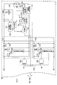
- Blade 100 ... Drive circuit, 101 ... First positive terminal, 102 ... First negative terminal, 103 ... First 1 signal terminal, 104 ... second positive terminal, 105 ... second negative terminal, 106 ... second signal terminal, 110 ... MCU, 111 ... power supply circuit, 112a ... first voltage division 112b, second voltage divider, 112c, third voltage divider, 113a, first display circuit, 113b, second display circuit, 113c, third display circuit, 114a, first current detection circuit, 114b, second current detection.
- Circuit 114c Third current detection circuit 115a First boost circuit 115b Second boost circuit 116 Boost voltage setting circuit 117 Overcurrent detection circuit 118a First operation circuit 118b Second operation Circuits, 119a, 119b ... FET, 120a, 120b ... overcurrent detection circuit, 121 ... operation detection circuit, 122 ... voltage divider, 123 ... error amplifier, 124 ... triangular wave generator, 125 ... comparator, 200 ... drive circuit, 211a ... 1st FET, 211b ... 2nd FET, 212 ... Power supply circuit, 300 ... Drive circuit, 301 ... FET, 302 ... PWM signal generator, 316 ... Boosting power Setting circuit, 400 ... driving circuit, 401 ... third positive terminal, 402 ... third negative terminal, 403 ... third signal terminal, 500 ... power tool, 501 ... main body, 502 ... battery pack attachment portion
- the electric machine instrument (hereinafter abbreviated as instrument) 1 of the first embodiment is configured as an electric working machine, and more specifically, cuts grass and small-diameter trees. It is configured as a brush cutter.
- the main body 2 of the instrument 1 includes a motor unit 3 and a shaft pipe 5 connected to one end of the motor unit 3.
- the motor unit 3 houses a drive circuit 100 (described later) including a motor M1 (described later) inside the motor unit 3.
- the motor unit 3 is provided with a battery pack mounting portion 7 on the other end of the motor unit 3 for detachably mounting the first battery pack 4a and the second battery pack 4b. More specifically, the battery pack mounting part 7 slides the first battery pack 4a and the second battery pack 4b on the battery pack mounting part 7 in the directions indicated by the arrows in the drawing, respectively. 4a and the 2nd battery pack 4b are comprised so that attachment or detachment is possible respectively.
- the battery pack mounting portion 7 is provided with a pair of hooks that engage with the first battery pack 4a and the second battery pack 4b mounted on the battery pack mounting portion 7, and the pair of hooks is used to The first battery pack 4 a and the second battery pack 4 b are fixed to the battery pack mounting portion 7.
- the motor unit 3 is provided with an indicator 6 on one side of the motor unit 3 for notifying the user of the appliance 1 of the state of each of the first battery pack 4a and the second battery pack 4b.
- the display device 6 may be any type of display device, and the display device 6 in the first embodiment is a display device including two LEDs. More specifically, the display device 6 includes a first LED 6a and a second LED 6b.
- the first LED 6a is an LED for notifying the user of the state of the first battery pack 4a
- the second LED 6b is an LED for notifying the user of the state of the second battery pack 4b.
- the shaft pipe 5 is formed in a hollow rod shape, and a cutter mounting portion 9 for detachably mounting the cutter 8 is provided at the end of the shaft pipe 5 opposite to the motor unit 3.
- the cutter 8 is formed in a substantially disc shape as a whole. More specifically, the center portion of the cutter 8 is formed of a material having a rigidity equal to or higher than a predetermined value (for example, a metal material or a high hardness synthetic resin), and is formed into a disk shape or a cylindrical shape. Has been.
- a plurality of blades 81 are provided on the periphery of the cutter 8.
- a handle 10 is provided in the vicinity of an intermediate position in the axial direction of the shaft pipe 5.
- the handle 10 is provided with a right hand grip 11 for the user to hold with the right hand and a left hand grip 13 for the user to hold with the left hand.
- the right hand grip 11 is provided with a trigger switch 12 for the user to operate the rotation of the cutter 8.
- a transmission shaft (not shown) is accommodated in the shaft pipe 5.
- One end of the transmission shaft is connected to the rotor of a motor M1 (described later) housed in the motor unit 3, while the other end of the transmission shaft is connected to the cutter via a plurality of gears (not shown) provided in the cutter mounting portion 9. 8 is connected.
- the rotational driving force of the motor M1 is transmitted to the cutter 8 through the transmission shaft and the plurality of gears.
- the instrument 1 includes the drive circuit 100 described above, and the first battery pack 4 a and the second battery pack 4 b are electrically connected to the drive circuit 100.
- Each of the first battery pack 4a and the second battery pack 4b includes a battery 41a or a battery 41b, and each of the batteries 41a and 41b includes a plurality of battery cells connected in series.
- the number of battery cells included in each of the batteries 41a and 41b and the voltage generated by each battery cell may be set in any manner.
- each of the batteries 41a and 41b includes five battery cells, and each of these battery cells generates a voltage of 3.6 VDC.
- the batteries 41a and 41b in the first embodiment are configured to generate voltages VB1 and VB2 of 18 VDC, respectively.
- Each battery cell in the first embodiment is configured as a secondary battery (for example, a lithium ion secondary battery). That is, the first battery pack 4a and the second battery pack 4b in the first embodiment are each configured as a rechargeable battery pack.
- the positive electrode of the battery 41a is connected to the positive terminal 42a provided in the first battery pack 4a, and the voltage VB1 generated in the battery 41a is supplied to the drive circuit 100 via the positive terminal 42a. Is output.
- the negative electrode of the battery 41a is connected to a negative electrode terminal 43a provided in the first battery pack 4a.
- the positive electrode of the battery 41b is connected to the positive terminal 42b provided in the second battery pack 4b, and the voltage VB2 generated in the battery 41b is supplied to the drive circuit 100 via the positive terminal 42b. Is output.
- the negative electrode of the battery 41b is connected to a negative electrode terminal 43b provided in the second battery pack 4b.
- each of the first battery pack 4a and the second battery pack 4b includes a battery management unit (BMU) 44a or a BMU 44b.
- BMU battery management unit
- Each of the BMUs 44a and 44b detects overcharge and overdischarge of each battery cell based on the voltage between the positive electrode and the negative electrode of each battery cell in the battery 41a or the battery 41b.
- Each of the BMUs 44a and 44b outputs an overcharge detection signal indicating that overcharge has been detected and an overdischarge detection signal indicating that overdischarge has been detected. More specifically, the BMU 44a outputs an overdischarge detection signal to the drive circuit 100 via the output circuit 45a and the signal terminal 46a provided in the first battery pack 4a.
- the BMU 44b outputs an overdischarge detection signal to the drive circuit 100 via the output circuit 45b and the signal terminal 46b provided in the second battery pack 4b.
- the drive circuit 100 includes a first positive terminal 101, a first negative terminal 102, a first signal terminal 103, a second positive terminal 104, a second negative terminal 105, and a second signal terminal 106.
- the terminals are connected to the positive terminal 42a, the negative terminal 43a, the signal terminal 46a, the positive terminal 42b, the negative terminal 43b, and the signal terminal 46b, respectively.
- the drive circuit 100 further includes a main control unit (MCU) 110, a power supply circuit 111, a first voltage divider 112a, a second voltage divider 112b, a first display circuit 113a, a second display circuit 113b, A first current detection circuit 114a and a second current detection circuit 114b are provided.
- MCU main control unit
- the MCU 110 controls various operations of the appliance 1.
- the MCU 110 in the first embodiment is a microcomputer including at least a CPU, a memory (eg, ROM, RAM, etc.), an I / O, and the like.
- the power supply circuit 111 is connected to the first positive electrode terminal 101 via the diode D1, and receives the voltage VB1 output from the first battery pack 4a.
- the power supply circuit 111 is further connected to the second positive electrode terminal 104 via the diode D2, and receives the voltage VB2 output from the second battery pack 4b.
- the power circuit 111 generates a control voltage Vcc for driving various circuits in the drive circuit 100 including the MCU 110 from one of the voltages VB1 and VB2 output from the first battery pack 4a and the second battery pack 4b.
- the controlled voltage Vcc is supplied to these various circuits.
- the diode D1 is provided to suppress a current from flowing from the second battery pack 4b to the first battery pack 4a via the power supply circuit 111, while the diode D2 is provided from the first battery pack 4a. It is provided to suppress the current from flowing into the second battery pack 4b via 111.
- the remaining amount of power in one battery pack of the first battery pack 4a and the second battery pack 4b is low, the other battery pack of the first battery pack 4a and the second battery pack 4b It is possible to suppress the occurrence of current flowing into one battery pack due to electric power and damage to one battery pack.
- the first voltage divider 112a divides the voltage VB1 input from the first battery pack 4a via the first positive electrode terminal 101, and outputs the divided voltage to the MCU 110.
- the second voltage divider 112b divides the voltage VB2 input from the second battery pack 4b via the second positive terminal 104 and outputs the divided voltage to the MCU 110.
- the first display circuit 113a is a circuit for lighting the first LED 6a described above, and lights the first LED 6a in accordance with a command output from the MCU 110.
- the second display circuit 113b is a circuit for lighting the above-described second LED 6b, and lights the second LED 6b in accordance with a command output from the MCU 110.
- the first current detection circuit 114a is provided between the downstream side of the motor M1 and the first negative terminal 102, detects the magnitude of current flowing from the motor M1 to the first negative terminal 102, and detects the magnitude of the detected current. A signal indicating this is output to the MCU 110. Since the first negative electrode terminal 102 is connected to the ground of the drive circuit 100, when the first battery pack 4a is attached to the appliance 1, the potential of the negative electrode of the battery 41a in the first battery pack 4a (the first battery pack). 4a is the same potential as the ground of the drive circuit 100.
- the second current detection circuit 114b is provided between the downstream side of the motor M1 and the second negative terminal 105, detects the magnitude of the current flowing from the motor M1 to the second negative terminal 105, and detects the magnitude of the detected current. A signal indicating this is output to the MCU 110. Since the second negative electrode terminal 105 is connected to the ground of the drive circuit 100, when the second battery pack 4b is attached to the appliance 1, the potential of the negative electrode of the battery 41b in the second battery pack 4b (second battery pack). 4b) is at the same potential as the ground of the drive circuit 100.
- Each of the discharge stop signals is input to the MCU 110 via an interface circuit (not shown).
- Each of the discharge stop signals in the first embodiment is a binary signal. The logical value of each of these binary signals is high when discharging is continued, and is high impedance when discharging is stopped.
- the drive circuit 100 further includes a first booster circuit 115a, a second booster circuit 115b, a boosted voltage setting circuit 116, the motor M1, the overcurrent detection circuit 117, and the first booster circuit 115b.
- An operation circuit 118a and a second operation circuit 118b are provided.
- the first booster circuit 115a has the input side of the first booster circuit 115a connected to the first positive terminal 101, boosts the voltage VB1 input from the first battery pack 4a via the first positive terminal 101, and the motor M1. A drive voltage for driving is generated.
- the first booster circuit 115a in the first embodiment is a known step-up converter.
- the first booster circuit 115a includes a capacitor C1a, a transformer Ta, an N-channel FET 119a, an overcurrent detection circuit 120a, a diode D3a, and a capacitor C2a.
- the capacitor C1a is connected between the first positive terminal 101 and the ground of the drive circuit 100, and is set so as to store electric charge by the drive voltage VB1.
- the transformer Ta includes a primary side coil and a secondary side coil. One end of the primary coil is connected to the first positive terminal 101, while the other end of the primary coil is connected to the drain of the FET 119a. One end of the secondary side coil of the transformer Ta is connected to the upstream side of the motor M1 via the diode D3a and the boost voltage setting circuit 116, while the other end of the secondary side coil is connected to the ground of the drive circuit 100. ing.
- the FET 119a has a source connected to the ground of the drive circuit 100 via the overcurrent detection circuit 120a, and the FET 119a is turned on / off by a voltage input to the gate of the FET 119a. It is set to switch the flowing current.
- the overcurrent detection circuit 120a monitors the current flowing from the primary coil of the transformer Ta to the ground of the drive circuit 100 via the FET 119a, and outputs a binary signal indicating whether or not an overcurrent has been detected.
- the logical value of the binary signal is Low when an overcurrent is detected, and High when no overcurrent is detected.
- the diode D3a half-rectifies the AC voltage generated in the secondary coil of the transformer Ta, and the capacitor C2a generates a smoothed drive voltage by smoothing the voltage half-wave rectified by the diode D3a. To do.
- the second booster circuit 115b has the input side of the second booster circuit 115b connected to the second positive terminal 104, boosts the voltage VB2 input from the second battery pack 4b via the second positive terminal 104, and the motor M1. A drive voltage for driving is generated.
- the second booster circuit 115b in the first embodiment is configured similarly to the first booster circuit 115a.
- the second booster circuit 115b includes a capacitor C1b, a transformer Tb, an N-channel FET 119b, an overcurrent detection circuit 120b, a diode D3b, and a capacitor C2b.
- the capacitor C1b is connected between the second positive terminal 104 and the ground of the drive circuit 100, and is set to store electric charge by the drive voltage VB2.
- the transformer Tb includes a primary side coil and a secondary side coil. One end of the primary side coil is connected to the second positive terminal 104, while the other end of the primary side coil is connected to the drain of the FET 119b. One end of the secondary side coil of the transformer Tb is connected to the upstream side of the motor M1 via the diode D3b and the boost voltage setting circuit 116, while the other end of the secondary side coil is connected to the ground of the drive circuit 100. ing.
- the source of the FET 119b is connected to the ground of the drive circuit 100 via the overcurrent detection circuit 120b, and the FET 119b is turned on / off by a voltage input to the gate of the FET 119b. It is set to switch the flowing current.
- the overcurrent detection circuit 120b monitors the current flowing from the primary coil of the transformer Tb to the ground of the drive circuit 100 via the FET 119b, and outputs a binary signal indicating whether or not an overcurrent has been detected.
- the logical value of the binary signal is Low when an overcurrent is detected, and High when no overcurrent is detected.
- the diode D3b rectifies the AC voltage generated in the secondary coil of the transformer Tb by half-wave rectification, and the capacitor C2b generates the smoothed drive voltage by smoothing the voltage rectified by the diode D3b by half-wave. To do.
- the boost voltage setting circuit 116 includes a main switch SW1, a variable resistor R1, a switch (SW) operation detection circuit 121, a voltage divider 122, an error amplifier 123, a triangular wave generator 124, and a comparator 125. ing.
- the main switch SW1 has one contact of the main switch SW1 connected to the diodes D3a and D3b, and the other contact of the main switch SW1 connected to the upstream side of the motor M1.
- the main switch SW1 is configured to be interlocked with the above-described trigger switch 12. When the trigger switch 12 is operated, the main switch SW1 is turned on, and the diodes D3a and D3b are connected to the motor M1 via the main switch SW1. Connected upstream. On the other hand, when the trigger switch 12 is not operated, the main switch SW1 is turned off, and the diodes D3a and D3b are disconnected from the upstream side of the motor M1.
- the variable resistor R1 is set to divide the control voltage Vcc and generate a divided voltage.
- the variable resistor R1 is configured to be interlocked with the trigger switch 12, and the resistance value of the variable resistor R1 changes according to the operation amount of the trigger switch 12. That is, the variable resistor R1 generates a voltage corresponding to the operation amount of the trigger switch 12.
- the SW operation detection circuit 121 is a circuit that detects that the trigger switch 12 is operated. More specifically, the voltage between the contacts of the main switch SW1 is input to the SW operation detection circuit 121. The SW operation detection circuit 121 operates the trigger switch 12 based on the voltage between the contacts. A binary signal indicating whether or not it has been output is output to the MCU 110. The logical value of the binary signal becomes High when the trigger switch 12 is operated, and becomes Low when the trigger switch 12 is not operated.
- the voltage divider 122 divides the drive voltage generated in the first booster circuit 115 a and the second booster circuit 115 b and outputs the divided voltage to the MCU 110 and the error amplifier 123.
- the error amplifier 123 amplifies the difference between the voltage divided by the voltage divider 122 and the voltage generated in the variable resistor R1, and outputs the amplified voltage.
- the triangular wave generator 124 repeatedly generates a preset triangular wave.
- the comparator 125 compares the voltage of the output signal from the error amplifier 123 with the voltage of the triangular wave from the triangular wave generator 124, and outputs a pulse train signal whose duty ratio changes according to the comparison result.
- the boost voltage setting circuit 116 is configured to output a pulse train signal having a larger duty ratio as the operation amount of the trigger switch 12 is larger, by the circuit configuration as described above.
- the motor M1 is a DC motor with a brush.
- a diode D4 for absorbing a counter electromotive force generated in the coil is connected in parallel to the coil of the motor M1.
- the overcurrent detection circuit 117 monitors the current flowing downstream of the motor M1 and outputs a binary signal indicating whether or not an overcurrent has been detected.
- the logical value of the binary signal is Low when an overcurrent is detected, and High when no overcurrent is detected.
- the first actuating circuit 118a is configured as an AND gate, a binary signal output from the overcurrent detection circuit 120a, a binary signal indicating whether or not boosting is output from the MCU 110, and a boosting voltage setting circuit
- the pulse train signal output from 116 and the binary signal output from the overcurrent detection circuit 117 are input.
- the logic value of the output voltage of the first operating circuit 118a becomes High when the logic values of all these binary signals are High, and the first value when the logic value of at least one signal is Low.
- the logical value of the output voltage of the 1 operation circuit 118a becomes Low.
- the boost voltage is detected only when the overcurrent is not detected by the overcurrent detection circuit 120a, the MCU 110 permits boosting, and the overcurrent detection circuit 117 detects no overcurrent.
- a pulse train signal synchronized with the pulse train signal output from the setting circuit 116 is output to the FET 119a.
- the FET 119a is switched by the pulse train signal output from the first operating circuit 118a.
- the voltage VB1 is boosted and a drive voltage is generated.
- the magnitude of the drive voltage is proportional to the magnitude of the duty ratio of the pulse train signal.
- the second operation circuit 118b is configured as an AND gate.
- the second operating circuit 118b is output from the binary signal output from the overcurrent detection circuit 120b, the above-described binary signal indicating whether or not to allow boosting from the MCU 110, and the boosting voltage setting circuit 116.
- the pulse train signal and the binary signal output from the overcurrent detection circuit 117 are input.
- the second operating circuit 118b when the logic values of all these binary signals are High, the logic value of the output voltage of the second operating circuit 118b is High, and when the logic value of at least one signal is Low, the second operating circuit 118b 2 The logic value of the output voltage of the operating circuit 118b becomes Low.
- the boost voltage is only detected when the overcurrent is not detected by the overcurrent detection circuit 120b, the MCU 110 permits the boosting, and the overcurrent detection circuit 117 does not detect the overcurrent.
- a pulse train signal synchronized with the pulse train signal output from the setting circuit 116 is output to the FET 119b.
- the FET 119b is switched by the pulse train signal output from the second operating circuit 118b. By switching the FET 119b, the voltage VB2 is boosted and a drive voltage is generated.
- the main routine according to the present invention executed by the MCU 110 will be described.
- the MCU 110 is activated.
- the main routine shown in the above is repeatedly executed.
- this main routine first, based on the logical value of the binary signal input from the SW operation detection circuit 121, it is determined whether or not the main switch SW1 is turned on (S10). If it is determined that the main switch SW1 is turned off (S10: No), the process proceeds to S40 described later.
- This priority setting process is a process of setting a battery pack (main battery) to be discharged preferentially and a battery pack (sub-battery) to be discharged auxiliary, and will be described in detail later.
- the priority setting process it is determined whether or not there is a battery pack corresponding to the main battery (S30).
- S30: No the value of the voltage VB1 of the first battery pack 4a is calculated based on the voltage input from the first voltage divider 112a, and the calculated value is used as the MCU 110. (S40).
- the value of the voltage VB2 of the second battery pack 4b is calculated based on the voltage input from the second voltage divider 112b, and the calculated value is stored in the memory (S50).
- S30 If it is determined in S30 that there is a battery pack corresponding to the main battery (S30: Yes), it corresponds to the battery pack set as the main battery among the first booster circuit 115a and the second booster circuit 115b.
- the booster circuit is activated to boost the voltage of the main battery (S80).
- the discharge from the battery pack set to the main battery based on the signal from the current detection circuit corresponding to the battery pack set to the main battery among the first current detection circuit 114a and the second current detection circuit 114b. It is determined whether or not the current is greater than or equal to a preset threshold value (S90). If it is determined that the discharge current is equal to or greater than the threshold (S90: Yes), it is determined whether there is a battery pack corresponding to the sub-battery (S100). When it is determined that there is no battery pack corresponding to the sub-battery (S100: No), the process proceeds to S120 described later.
- S90 a preset threshold value
- the booster circuit corresponding to the battery pack set as the sub-battery.
- the main routine is terminated.
- the priority setting process in S20 is executed as follows. That is, in this process, first, it is set in the memory of the MCU 110 that there is no battery pack corresponding to the main battery and that there is no battery pack corresponding to the sub battery (S200). Then, it is determined whether or not the first battery pack 4a is connected to the drive circuit 100 (S210). This determination is made based on the voltage input from the voltage divider 112a.
- the second battery pack 4b is set as the main battery (S270), and this process is terminated.
- the voltage is determined based on the values of the voltages VB1 and VB2 stored in the memory in S40 and 50 of the main routine. It is determined whether VB1 is equal to or higher than voltage VB2 (S280).
- the second battery pack 4b is set as a sub-battery (S290), and this process ends. On the other hand, if it is determined that the voltage VB1 is equal to or higher than the voltage VB2 (S280: Yes), the second battery pack 4b is set as the main battery and the first battery pack 4a is set as the sub-battery (S300). finish.
- the first booster circuit 115a and the first booster circuit 115a are selected from at least one of the first battery pack 4a and the second battery pack 4b selected by the MCU 110.
- a power supply path to the motor M1 is formed through at least one corresponding booster circuit of the two booster circuits 115b, and a drive voltage is applied to the motor M1.
- the battery pack with the smaller remaining power is set as the main battery. . For this reason, the power of the battery pack with the larger remaining power is consumed first, and the power of the battery pack with the smaller remaining power is consumed while the battery pack is replaced or charged.
- the use of the instrument 1 can be prevented from being interrupted.
- size of a drive voltage can be changed suitably according to the operation amount of the trigger switch 12.
- the first booster circuit 115a and the second booster circuit 115b correspond to an example of the booster in the present invention, and execute S230 to S300 in the priority setting process and S90 to S120 of the main routine.
- the MCU 110 corresponds to an example of a battery pack selection unit in the present invention, and the MCU 110 that executes S80 to S110 in the main routine corresponds to an example of a path formation unit in the present invention.
- the first current detection circuit 114a, the second current detection circuit 114b, and the MCU 110 that executes S90 of the main routine correspond to an example of the motor state detection unit in the present invention
- the first voltage divider 112a, the second voltage divider 112b, and the MCU 110 that executes S40 and 50 of the main routine correspond to an example of the battery pack state detection unit in the present invention
- the boost voltage setting circuit 116 corresponds to an example of the command unit in the present invention.
- the instrument in the second embodiment is the same as the instrument of the first embodiment except for the configuration of a part of the drive circuit, which is different from the first embodiment.
- a diode D5a and a P-channel type first FET 211a are composed of a primary side coil of a transformer Ta in the first positive terminal 101 and the first booster circuit 115a. Connected between and. More specifically, the anode of the diode D5a is connected to the first positive terminal 101, and the cathode of the diode D5a is connected to the source of the first FET 211a. The drain of the first FET 211a is connected to one end of the primary coil of the transformer Ta, and a drive signal is input from the MCU 210 to the gate of the first FET 211a.
- the diode D5b and the P-channel type second FET 211b are connected between the second positive terminal 104 and the primary coil of the transformer Ta. More specifically, the anode of the diode D5b is connected to the second positive terminal 104, and the cathode of the diode D5b is connected to the source of the second FET 211b. The drain of the second FET 211b is connected to one end of the primary side coil of the transformer Ta, and a drive signal is input from the MCU 210 to the gate of the second FET 211b.
- the drain of the first FET 211a and the drain of the second FET 211b are connected to the input side of the power supply circuit 212 provided in the drive circuit 200 of the second embodiment, and the first battery pack is connected via these FETs.
- the voltage VB1 of 4a and the voltage VB2 of the second battery pack 4b are input, and the control voltage Vcc is generated based on these voltages.
- the second operating circuit 118b and the second booster circuit 115b provided in the driving circuit 100 of the first embodiment are omitted.
- a main routine according to the present invention executed by the MCU 210 will be described.
- the MCU 210 When the control voltage Vcc is applied and the MCU 210 is activated, the MCU 210 repeatedly executes the main routine shown in FIG. As shown in FIG. 8, in this main routine, first, based on the logical value of the binary signal input from the SW operation detection circuit 121, it is determined whether or not the main switch SW1 is turned on (S400). If it is determined that the main switch SW1 is turned off (S400: No), the process proceeds to S430 described later.
- a drive signal having a logical value of High is output to the gate of the first FET 211a, the first FET 211a is turned off (S450), and a drive signal having a logical value of High is output to the gate of the second FET 211b.
- the 2FET 211b is turned off (S70).
- a binary signal whose logic value is Low is output to the first operating circuit 118a, the first booster circuit 115a is stopped (S470), and this main routine is terminated.
- the discharge from the battery pack set to the main battery based on the signal from the current detection circuit corresponding to the battery pack set to the main battery among the first current detection circuit 114a and the second current detection circuit 114b. It is determined whether or not the current is greater than or equal to a threshold value (S490). If it is determined that the discharge current is equal to or greater than the threshold (S490: Yes), it is determined whether there is a battery pack corresponding to the sub-battery (S500). If it is determined that there is no battery pack corresponding to the sub-battery (S500: No), the process proceeds to S520 described later.
- a threshold value S490
- S490 If it is determined in S490 that the discharge current is less than the threshold value (S490: No), a drive signal whose logic value is High is output to the gate of the FET corresponding to the battery pack set in the sub-battery. The FET is turned off (S520). Then, a binary signal whose logical value is High is output to the first operating circuit 118a, the first booster circuit 115a is operated (S530), and this main routine is terminated.
- both the voltage VB1 of the first battery pack 4a and the voltage VB2 of the second battery pack 4b can be boosted only by the first booster circuit 115a.
- the configuration of the drive circuit 200 can be simplified.
- the diodes D5a and D5b prevent the current from flowing back to the first battery pack 4a and the second battery pack 4b. For this reason, in the instrument of the second embodiment, it is possible to suppress the occurrence of problems in each of these battery packs due to the backflow of current to the first battery pack 4a and the second battery pack 4b.
- the diodes D5a and D5b correspond to an example of the backflow suppressing unit in the present invention.
- the instrument in the third embodiment is the same as the instrument of the first embodiment except for the configuration of a part of the drive circuit, which is different from the first embodiment.
- the appliance drive circuit 300 in the third embodiment is partially different in the configuration of the boost voltage setting circuit 316 from the configuration of the boost voltage setting circuit 116 in the first embodiment.
- the drive circuit 300 further includes an N-channel FET 301 and a PWM signal generator 302.
- the drain of the FET 301 is connected to the downstream side of the motor M ⁇ b> 1, and the source of the FET 301 is connected to the overcurrent detection circuit 117.
- the PWM signal generator 302 is connected to the gate of the FET 301, and outputs a pulse train signal having a duty ratio corresponding to the magnitude of the voltage generated by the variable resistor R1 to the gate of the FET 301 to switch the FET 301. More specifically, the PWM signal generator 302 outputs a pulse train signal having a larger duty ratio as the operation amount of the trigger switch 12 is larger.
- the PWM signal generator 302 corresponds to an example of a pulse width modulation unit in the present invention.
- the instrument according to the fourth embodiment is the same as the first embodiment and the second embodiment except for a part of the configuration of the instrument that differs from the first and second embodiments.
- the instrument according to the third embodiment includes a third battery pack 4c in addition to the first battery pack 4a and the second battery pack 4b.
- the third battery pack 4c is configured in the same manner as the first battery pack 4a and the second battery pack 4b.
- the drive circuit 400 according to the fourth embodiment is a combination of the drive circuit 100 in the first embodiment and the drive circuit 200 in the second embodiment. That is, in the drive circuit 400, the booster circuit corresponding to the first battery pack 4a and the second battery pack 4b is the first booster circuit 115a, and the booster circuit corresponding to the third battery pack 4c is the second booster circuit 115b. It is comprised so that.
- the drive circuit 400 is provided with a third positive terminal 401, a third negative terminal 402, and a third signal terminal 403.
- a third voltage divider 112c is provided for detecting the voltage of the third battery pack 4c
- a third display circuit 113c is provided for notifying the user of the instrument of the state of the third battery pack 4c.
- a third current detection circuit 114c is provided for detecting the discharge current of the third battery pack 4c.
- the MCU 410 selects at least one of the first battery pack 4a, the second battery pack 4b, and the third battery pack 4c based on the procedure as disclosed in the first embodiment and the second embodiment, The voltage of at least one selected battery pack is boosted to generate a drive voltage.
- the configuration of the drive circuit 400 can be simplified due to the provision of two booster circuits instead of three booster circuits for the three battery packs.
- the appliance to which the present invention is applied is configured as an electric working machine, but is configured as an electric tool 500 such as an impact driver shown in FIG. Also good.
- the electric power tool 500 the first battery pack 4a and the second battery pack 4b are detachably attached to a battery pack attachment portion 502 provided in the main body 501 of the electric power tool 500.
- the MCU is a microcomputer.
- the MCU may be configured by combining various individual electronic components, or may be an ASIC (Application Specific Integrated Circuit).
- ASIC Application Specific Integrated Circuit
- it may be a programmable logic device such as an FPGA (Field Programmable Gate Array), or a combination thereof.
- the motor M1 is a DC motor with a brush.
- the present invention can be applied to any motor such as a brushless DC motor, an AC motor, a stepping motor, or a linear motor. It is.
- the booster circuit is a step-up converter, but may be any form of booster circuit.
- the battery pack in the first to fourth embodiments is configured as a rechargeable secondary battery, but may be configured as a non-chargeable primary battery.
Abstract
The electric equipment in one aspect of the present invention is provided with a motor, multiple battery packs, a voltage-raising unit, a battery pack-selecting unit, and a pathway-forming unit. The voltage-raising unit raises the voltage of each of the multiple battery packs and generates a drive voltage for driving the motor. The battery pack-selecting unit selects at least one of the multiple battery packs on the basis of a previously established selection procedure. The pathway-forming unit forms an electric power supply pathway from the at least one battery pack, selected from the multiple battery packs by the battery pack-selecting unit, to the motor via the voltage-raising unit.
Description
本国際出願は、2013年2月1日に日本国特許庁に出願された日本国特許出願第2013-018653号に基づく優先権を主張するものであり、日本国特許出願第2013-018653号の全内容を本国際出願に援用する。
This international application claims priority based on Japanese Patent Application No. 2013-018653 filed with the Japan Patent Office on February 1, 2013, and is based on Japanese Patent Application No. 2013-018653. The entire contents are incorporated into this international application.
本発明は、電動機械器具に関する。
The present invention relates to an electric machine instrument.
下記特許文献1に開示された電動工具は、当該電動工具の本体に2つのバッテリパックを装着可能に構成されている。この電動工具では、当該電動工具の本体に装着された2つのバッテリパックが直列接続されることによって、当該電動工具を適切に駆動するのに必要な電圧を得ている。
The electric power tool disclosed in the following Patent Document 1 is configured so that two battery packs can be attached to the main body of the electric power tool. In this electric power tool, two battery packs mounted on the main body of the electric power tool are connected in series to obtain a voltage necessary for appropriately driving the electric power tool.
上述の電動工具では、2つのバッテリパックのうちの一方における電力の残量が少なくなることなどに起因して、この一方のバッテリパックの電圧が著しく低下すると、当該電動工具を適切に駆動するのに必要な電圧を得ることができず、当該電動工具を適切に駆動できなくなってしまう可能性がある。
In the power tool described above, when the voltage of one of the two battery packs is significantly reduced due to a decrease in the remaining amount of power in one of the two battery packs, the power tool is appropriately driven. Therefore, there is a possibility that the voltage required for the power tool cannot be obtained and the electric tool cannot be driven properly.
そこで、本発明の1つの局面は、1つのバッテリパックが出力可能な電圧よりも高い電圧によって適切に駆動する電動機械器具を1つのバッテリパックの電圧が著しく低下しても適切に駆動させることが可能な技術を提供できることが望ましい。
Accordingly, one aspect of the present invention is to appropriately drive an electric machine instrument that is appropriately driven by a voltage higher than a voltage that can be output by one battery pack even if the voltage of one battery pack is significantly reduced. It would be desirable to be able to provide possible technology.
本発明の1つの局面における電動機械器具は、モータと、複数のバッテリパックと、昇圧部と、バッテリパック選択部と、経路形成部とを備えている。
昇圧部は、複数のバッテリパックの各々の電圧を昇圧して、モータを駆動するための駆動電圧を生成する。バッテリパック選択部は、予め設定された選択手順に基づいて、複数のバッテリパックの少なくとも1つを選択する。経路形成部は、バッテリパック選択部によって選択された複数のバッテリパックの少なくとも1つから昇圧部を介してモータに至る電力供給経路を形成する。 An electric machine instrument according to one aspect of the present invention includes a motor, a plurality of battery packs, a boosting unit, a battery pack selecting unit, and a path forming unit.
The boosting unit boosts the voltage of each of the plurality of battery packs to generate a driving voltage for driving the motor. The battery pack selection unit selects at least one of the plurality of battery packs based on a preset selection procedure. The path forming unit forms a power supply path from at least one of the plurality of battery packs selected by the battery pack selecting unit to the motor via the boosting unit.
つまり、このように構成された電動機械器具では、選択手順に基づいて選択された少なくとも1つのバッテリパックから昇圧部を介してモータに至る電力供給経路を通じて、モータに駆動電圧が印加される。
That is, in the electric machine instrument configured as described above, the drive voltage is applied to the motor through the power supply path from at least one battery pack selected based on the selection procedure to the motor via the booster.
したがって、この電動機械器具では、複数のバッテリパックの1つの電圧が著しく低下しても、残りのバッテリパックの電圧を用いて生成される駆動電圧によってモータを駆動することができる。
Therefore, in this electric machine instrument, even if the voltage of one of the plurality of battery packs is significantly reduced, the motor can be driven by the drive voltage generated using the voltages of the remaining battery packs.
尚、選択手順はどのように設定されていてもよい。例えば、選択手順は、複数のバッテリパックのうちの1つのみを選択するように設定されていてもよい。あるいは、複数のバッテリパックの全てを選択するように設定されていてもよい。複数のバッテリパックを選択するように設定されている場合には、1つのバッテリパックが出力可能な電力よりも大きな電力でモータを駆動する必要がある場合にモータを適切に駆動することができる。
Note that the selection procedure may be set in any way. For example, the selection procedure may be set to select only one of the plurality of battery packs. Alternatively, it may be set to select all of the plurality of battery packs. When it is set to select a plurality of battery packs, the motor can be appropriately driven when it is necessary to drive the motor with electric power larger than the electric power that can be output by one battery pack.
電動機械器具は、モータの状態を検出するモータ状態検出部を備えていてもよく、バッテリパック選択部は、モータ状態検出部によって検出されたモータの状態に基づいて、複数のバッテリパックの少なくとも1つを選択するように構成されていてもよい。
The electric machine apparatus may include a motor state detection unit that detects a state of the motor, and the battery pack selection unit is based on at least one of the plurality of battery packs based on the motor state detected by the motor state detection unit. It may be configured to select one.
このように構成された電動機械器具では、モータの状態に基づいて少なくとも1つのバッテリパックを選択することができる。
モータ状態検出部は、モータのあらゆる状態をどのように検出してもよい。 In the electric machine instrument configured as described above, at least one battery pack can be selected based on the state of the motor.
The motor state detection unit may detect any state of the motor in any way.
モータ状態検出部は、モータのあらゆる状態をどのように検出してもよい。 In the electric machine instrument configured as described above, at least one battery pack can be selected based on the state of the motor.
The motor state detection unit may detect any state of the motor in any way.
例えば、モータ状態検出部は、モータにかかる負荷を検出するように構成されていてもよい。この場合、バッテリパック選択部は、モータ状態検出部によって検出された負荷が予め設定された閾値以上であれば、複数のバッテリパックの少なくとも2つを選択し、モータ状態検出部によって検出された負荷が閾値未満であれば、複数のバッテリパックの1つを選択するように構成されていてもよい。
For example, the motor state detection unit may be configured to detect a load applied to the motor. In this case, the battery pack selection unit selects at least two of the plurality of battery packs if the load detected by the motor state detection unit is equal to or greater than a preset threshold, and the load detected by the motor state detection unit. May be configured to select one of a plurality of battery packs.
このように構成された電動機械器具では、モータにかかっている負荷が大きく、モータを駆動するのに大きな電力が必要な場合に、少なくとも2つのバッテリパックからモータに電力を供給できる一方、モータにかかっている負荷が小さければ1つのバッテリパックからモータに電力を供給できる。
In the electric machine apparatus configured as described above, when a large load is applied to the motor and a large amount of electric power is required to drive the motor, power can be supplied to the motor from at least two battery packs. If the applied load is small, power can be supplied from one battery pack to the motor.
モータ状態検出部は、モータにかかる負荷をどのように検出してもよい。例えば、モータ状態検出部は、モータに流れる電流、モータの回転数、及びモータの温度の少なくとも1つに基づいて、モータにかかる負荷を検出してもよい。
The motor state detection unit may detect the load applied to the motor in any way. For example, the motor state detection unit may detect a load applied to the motor based on at least one of a current flowing through the motor, a rotation speed of the motor, and a temperature of the motor.
電動機械器具は、複数のバッテリパックの各々の状態を検出するバッテリパック状態検出部を備えてもよい。この場合、バッテリパック選択部は、バッテリパック状態検出部によって検出された複数のバッテリパックの各々の状態に基づいて、複数のバッテリパックの少なくとも1つを選択するように構成されていてもよい。
The electric machine instrument may include a battery pack state detection unit that detects the state of each of the plurality of battery packs. In this case, the battery pack selection unit may be configured to select at least one of the plurality of battery packs based on each state of the plurality of battery packs detected by the battery pack state detection unit.
このように構成された電動機械器具では、複数のバッテリパックの各々の状態に基づいて、少なくとも1つのバッテリパックを選択することができる。
バッテリパック状態検出部は、複数のバッテリパックのあらゆる状態をどのように検出してもよい。 In the electric machine instrument configured as described above, at least one battery pack can be selected based on the state of each of the plurality of battery packs.
The battery pack state detection unit may detect any state of the plurality of battery packs.
例えば、バッテリパック状態検出部は、複数のバッテリパックの各々における電力の残量を検出するように構成されていてもよい。この場合、バッテリパック選択部は、バッテリパック状態検出部によって検出された複数のバッテリパックの各々における電力の残量に基づいて、複数のバッテリパックの少なくとも1つを選択するように構成されていてもよい。
For example, the battery pack state detection unit may be configured to detect the remaining amount of power in each of the plurality of battery packs. In this case, the battery pack selection unit is configured to select at least one of the plurality of battery packs based on the remaining amount of power in each of the plurality of battery packs detected by the battery pack state detection unit. Also good.
このように構成された電動機械器具では、複数のバッテリパックの各々における電力の残量に基づいて、少なくとも1つのバッテリパックを選択することができる。
この場合、バッテリパック選択部は、複数のバッテリパックの各々における電力の残量に基づいて、少なくとも1つのバッテリパックをどのように選択してもよい。例えば、バッテリパック選択部は、複数のバッテリパックからバッテリパック状態検出部によって検出された電力の残量が最も少ないバッテリパックを選択するように構成されていてもよい
。 In the electric machine instrument configured as described above, at least one battery pack can be selected based on the remaining amount of electric power in each of the plurality of battery packs.
In this case, the battery pack selection unit may select at least one battery pack based on the remaining amount of power in each of the plurality of battery packs. For example, the battery pack selection unit may be configured to select a battery pack with the smallest remaining amount of power detected by the battery pack state detection unit from a plurality of battery packs.
この場合、電力の残量に余裕があるバッテリパックが先に選択されて、その電力が先に消費され、このバッテリパックを交換あるいは充電している間に、残りのバッテリパックの電力が全て消費され、電動機械器具の使用が中断されることを抑制できる。
In this case, a battery pack with sufficient remaining power is selected first, the power is consumed first, and all the remaining battery pack power is consumed while this battery pack is replaced or charged. Thus, it is possible to prevent the use of the electric machine tool from being interrupted.
昇圧部は、複数のバッテリパックの各々の電圧をどのように昇圧してもよい。
例えば、昇圧部は、指令に応じて駆動電圧の大きさを変更可能に構成されていてもよい。この場合、電動機械器具は、さらに、昇圧部に駆動電圧の大きさを指令する指令部を備えていてもよい。 The boosting unit may boost the voltage of each of the plurality of battery packs.
For example, the boosting unit may be configured to be able to change the magnitude of the drive voltage in accordance with a command. In this case, the electric machine instrument may further include a command unit that commands the boosting unit to specify the magnitude of the drive voltage.
このように構成された電動機械器具では、駆動電圧の大きさを適宜変更することができる。
電動機械器具は、さらに、モータに印加される駆動電圧をパルス幅変調するパルス幅変調部を備えてもよい。 In the electric machine instrument configured as described above, the magnitude of the drive voltage can be appropriately changed.
The electric machine instrument may further include a pulse width modulation unit that performs pulse width modulation on the drive voltage applied to the motor.
このように構成された電動機械器具では、抵抗器などのようなモータに流れる電流を調整するための構成を別途設ける必要がなく、簡素な構成によってモータに流れる電流を適宜調整することができる。
It is not necessary to separately provide a configuration for adjusting the current flowing through the motor, such as a resistor, in the electric machine instrument configured as described above, and the current flowing through the motor can be appropriately adjusted with a simple configuration.
昇圧部は、複数のバッテリパックの各々に接続された複数の昇圧回路を備えていてもよく、複数の昇圧回路の数は、複数のバッテリパックの数と同じであってもよい。
この場合、複数のバッテリパックの間を直接接続する必要がなくなるため、一方のバッテリパックから他方のバッテリパックへ電流が流れ込むことを抑制できる。 The boosting unit may include a plurality of boosting circuits connected to each of the plurality of battery packs, and the number of the plurality of boosting circuits may be the same as the number of the plurality of battery packs.
In this case, since it is not necessary to directly connect a plurality of battery packs, it is possible to suppress a current from flowing from one battery pack to the other battery pack.
あるいは、複数の昇圧回路の数は、複数のバッテリパックの数よりも少なくてもよい。
この場合、複数のバッテリパックの数と同じ数だけ昇圧回路を設けるよりも昇圧部の構成を簡素化することができる。 Alternatively, the number of the plurality of booster circuits may be smaller than the number of the plurality of battery packs.
In this case, the configuration of the boosting unit can be simplified as compared to providing the same number of boosting circuits as the number of battery packs.
あるいは、昇圧部は、単一の昇圧回路を備えていてもよい。
この場合、昇圧部の構成を最も簡素化することができる。
さらに、この場合、複数のバッテリパックの各々に電流が逆流するのを抑制する逆流抑制部を備えていてもよい。 Alternatively, the booster unit may include a single booster circuit.
In this case, the configuration of the booster can be simplified most.
Furthermore, in this case, a backflow suppression unit that suppresses the backflow of current to each of the plurality of battery packs may be provided.
このように構成された電動機械器具では、複数のバッテリパックの各々に電流が逆流して、複数のバッテリパックの各々に問題が生じることを抑制できる。
電動機械器具は、複数のバッテリパックの各々を離脱不能に構成されていてもよい。 In the electric machine instrument configured as described above, it is possible to suppress the occurrence of a problem in each of the plurality of battery packs due to the current flowing back to each of the plurality of battery packs.
The electric machine instrument may be configured such that each of the plurality of battery packs cannot be detached.
あるいは、電動機械器具は、複数のバッテリパックの各々を離脱可能に装着する装着部を備えていてもよい。
このように構成された電動機械器具では、電圧が著しく低下したバッテリパックを容易に交換でき、ひいては当該電動機械器具の使用を容易に継続できる。 Alternatively, the electric machine instrument may include a mounting portion that detachably mounts each of the plurality of battery packs.
In the electric machine instrument configured as described above, the battery pack whose voltage is remarkably lowered can be easily replaced, and as a result, the use of the electric machine instrument can be easily continued.
本発明に係る電動機械器具は、例えば、電動工具であってもよいし、電動作業機であってもよい。
本発明の別の局面における、電動機械器具の本体は、モータと、装着部と、昇圧部と、バッテリパック選択部と、経路形成部とを備えている。 The electric machine instrument according to the present invention may be, for example, an electric tool or an electric work machine.
According to another aspect of the present invention, the main body of the electric machine instrument includes a motor, a mounting portion, a boosting portion, a battery pack selecting portion, and a path forming portion.
装着部には、複数のバッテリパックが装着される。昇圧部は、装着部に装着される複数のバッテリパックの各々の電圧を昇圧して、モータを駆動するための駆動電圧を生成する。バッテリパック選択部は、予め設定された選択手順に基づいて、複数のバッテリパックの少なくとも1つを選択する。経路形成部は、バッテリパック選択部によって選択された複数のバッテリパックの少なくとも1つから昇圧部を介してモータに至る電力供給経路を形成する。
* A plurality of battery packs are mounted on the mounting part. The boosting unit boosts the voltage of each of the plurality of battery packs mounted on the mounting unit to generate a driving voltage for driving the motor. The battery pack selection unit selects at least one of the plurality of battery packs based on a preset selection procedure. The path forming unit forms a power supply path from at least one of the plurality of battery packs selected by the battery pack selecting unit to the motor via the boosting unit.
このように構成された本体では、選択手順に基づいて選択された少なくとも1つのバッテリパックから昇圧部を介してモータに至る電力供給経路を通じて、モータに駆動電圧が印加される。
In the main body configured in this way, a drive voltage is applied to the motor through a power supply path from at least one battery pack selected based on the selection procedure to the motor via the booster.
つまり、本発明の別の局面は、本発明の上述の1つの局面と同様の効果を発揮し得る。
That is, another aspect of the present invention can exhibit the same effect as the above-described one aspect of the present invention.
1…器具、2…本体、3…モータユニット、4a…第1バッテリパック、4b…第2バッテリパック、4c…第3バッテリパック、5…シャフトパイプ、6…表示器、6a…第1LED、6b…第2LED、7…バッテリパック装着部、8…カッター、9…カッター装着部、10…ハンドル、11…右手グリップ、12…トリガスイッチ、13…左手グリップ、41a,41b…バッテリ、42a,42b…正極端子、43a,43b…負極端子、45a,45b…出力回路、46a,46b…信号端子、81…刃、100…駆動回路、101…第1正極端子、102…第1負極端子、103…第1信号端子、104…第2正極端子、105…第2負極端子、106…第2信号端子、110…MCU、111…電源回路、112a…第1分圧器、112b…第2分圧器、112c…第3分圧器、113a…第1表示回路、113b…第2表示回路、113c…第3表示回路、114a…第1電流検出回路、114b…第2電流検出回路、114c…第3電流検出回路、115a…第1昇圧回路、115b…第2昇圧回路、116…昇圧電圧設定回路、117…過電流検出回路、118a…第1作動回路、118b…第2作動回路、119a,119b…FET、120a,120b…過電流検出回路、121…操作検出回路、122…分圧器、123…エラーアンプ、124…三角波発生器、125…比較器、200…駆動回路、211a…第1FET、211b…第2FET、212…電源回路、300…駆動回路、301…FET、302…PWM信号発生器、316…昇圧電圧設定回路、400…駆動回路、401…第3正極端子、402…第3負極端子、403…第3信号端子、500…電動工具、501…本体、502…バッテリパック装着部
DESCRIPTION OF SYMBOLS 1 ... Apparatus, 2 ... Main body, 3 ... Motor unit, 4a ... 1st battery pack, 4b ... 2nd battery pack, 4c ... 3rd battery pack, 5 ... Shaft pipe, 6 ... Indicator, 6a ... 1st LED, 6b 2nd LED, 7 ... Battery pack mounting part, 8 ... Cutter, 9 ... Cutter mounting part, 10 ... Handle, 11 ... Right hand grip, 12 ... Trigger switch, 13 ... Left hand grip, 41a, 41b ... Battery, 42a, 42b ... Positive terminal, 43a, 43b ... Negative terminal, 45a, 45b ... Output circuit, 46a, 46b ... Signal terminal, 81 ... Blade, 100 ... Drive circuit, 101 ... First positive terminal, 102 ... First negative terminal, 103 ... First 1 signal terminal, 104 ... second positive terminal, 105 ... second negative terminal, 106 ... second signal terminal, 110 ... MCU, 111 ... power supply circuit, 112a ... first voltage division 112b, second voltage divider, 112c, third voltage divider, 113a, first display circuit, 113b, second display circuit, 113c, third display circuit, 114a, first current detection circuit, 114b, second current detection. Circuit 114c Third current detection circuit 115a First boost circuit 115b Second boost circuit 116 Boost voltage setting circuit 117 Overcurrent detection circuit 118a First operation circuit 118b Second operation Circuits, 119a, 119b ... FET, 120a, 120b ... overcurrent detection circuit, 121 ... operation detection circuit, 122 ... voltage divider, 123 ... error amplifier, 124 ... triangular wave generator, 125 ... comparator, 200 ... drive circuit, 211a ... 1st FET, 211b ... 2nd FET, 212 ... Power supply circuit, 300 ... Drive circuit, 301 ... FET, 302 ... PWM signal generator, 316 ... Boosting power Setting circuit, 400 ... driving circuit, 401 ... third positive terminal, 402 ... third negative terminal, 403 ... third signal terminal, 500 ... power tool, 501 ... main body, 502 ... battery pack attachment portion
以下に本発明の例示的な実施形態を図面と共に説明する。
[第1実施形態]
〈電動機械器具の全体構成〉
図1に示すように、本第1実施形態の電動機械器具(以下、器具と略称する)1は、電動作業機として構成され、より具体的には、草や小径木を刈り払う、所謂、刈払機として構成されている。 Hereinafter, exemplary embodiments of the present invention will be described with reference to the drawings.
[First Embodiment]
<Overall configuration of electric machinery / equipment>
As shown in FIG. 1, the electric machine instrument (hereinafter abbreviated as instrument) 1 of the first embodiment is configured as an electric working machine, and more specifically, cuts grass and small-diameter trees. It is configured as a brush cutter.
器具1の本体2は、モータユニット3と、モータユニット3の一端に連結されたシャフトパイプ5とを備えている。
モータユニット3は、当該モータユニット3の内部に後述のモータM1を含む後述の駆動回路100を収納している。さらに、モータユニット3は、当該モータユニット3の他端に、第1バッテリパック4aと第2バッテリパック4bとを離脱可能に装着するバッテリパック装着部7が設けられている。より具体的には、バッテリパック装着部7は、当該バッテリパック装着部7上で第1バッテリパック4a及び第2バッテリパック4bをそれぞれ図中矢印に示す方向にスライドさせることによって、第1バッテリパック4a及び第2バッテリパック4bをそれぞれ着脱可能に構成されている。バッテリパック装着部7には、当該バッテリパック装着部7に装着された第1バッテリパック4a及び第2バッテリパック4bに係合する1対のフックが設けられており、この1対のフックによって第1バッテリパック4a及び第2バッテリパック4bがバッテリパック装着部7に固定される。 Themain body 2 of the instrument 1 includes a motor unit 3 and a shaft pipe 5 connected to one end of the motor unit 3.
Themotor unit 3 houses a drive circuit 100 (described later) including a motor M1 (described later) inside the motor unit 3. Further, the motor unit 3 is provided with a battery pack mounting portion 7 on the other end of the motor unit 3 for detachably mounting the first battery pack 4a and the second battery pack 4b. More specifically, the battery pack mounting part 7 slides the first battery pack 4a and the second battery pack 4b on the battery pack mounting part 7 in the directions indicated by the arrows in the drawing, respectively. 4a and the 2nd battery pack 4b are comprised so that attachment or detachment is possible respectively. The battery pack mounting portion 7 is provided with a pair of hooks that engage with the first battery pack 4a and the second battery pack 4b mounted on the battery pack mounting portion 7, and the pair of hooks is used to The first battery pack 4 a and the second battery pack 4 b are fixed to the battery pack mounting portion 7.
モータユニット3は、当該モータユニット3の内部に後述のモータM1を含む後述の駆動回路100を収納している。さらに、モータユニット3は、当該モータユニット3の他端に、第1バッテリパック4aと第2バッテリパック4bとを離脱可能に装着するバッテリパック装着部7が設けられている。より具体的には、バッテリパック装着部7は、当該バッテリパック装着部7上で第1バッテリパック4a及び第2バッテリパック4bをそれぞれ図中矢印に示す方向にスライドさせることによって、第1バッテリパック4a及び第2バッテリパック4bをそれぞれ着脱可能に構成されている。バッテリパック装着部7には、当該バッテリパック装着部7に装着された第1バッテリパック4a及び第2バッテリパック4bに係合する1対のフックが設けられており、この1対のフックによって第1バッテリパック4a及び第2バッテリパック4bがバッテリパック装着部7に固定される。 The
The
また、さらに、モータユニット3は、当該モータユニット3の一側面に、第1バッテリパック4a及び第2バッテリパック4bの各々の状態を器具1の使用者に報知するための表示器6が設けられている。表示器6は、どのような形態の表示器であってもよく、本第1実施形態における表示器6は2つのLEDを備える表示器である。より具体的には、表示器6は、第1LED6aと、第2LED6bとを備えている。第1LED6aは、第1バッテリパック4aの状態を使用者に報知するためのLEDであり、第2LED6bは、第2バッテリパック4bの状態を使用者に報知するためのLEDである。
Furthermore, the motor unit 3 is provided with an indicator 6 on one side of the motor unit 3 for notifying the user of the appliance 1 of the state of each of the first battery pack 4a and the second battery pack 4b. ing. The display device 6 may be any type of display device, and the display device 6 in the first embodiment is a display device including two LEDs. More specifically, the display device 6 includes a first LED 6a and a second LED 6b. The first LED 6a is an LED for notifying the user of the state of the first battery pack 4a, and the second LED 6b is an LED for notifying the user of the state of the second battery pack 4b.
シャフトパイプ5は、中空棒状に形成され、シャフトパイプ5における、モータユニット3とは反対側の端部には、カッター8を離脱可能に装着するカッター装着部9が設けられている。カッター8は、全体として略円板状に形成されている。より具体的には、カッター8の中心部は、予め規定された規定値以上の剛性を有した材料(例えば、金属材料や高硬度の合成樹脂)で形成され、円板状又は円柱状に成形されている。また、カッター8の周縁には、複数の刃81が設けられている。
The shaft pipe 5 is formed in a hollow rod shape, and a cutter mounting portion 9 for detachably mounting the cutter 8 is provided at the end of the shaft pipe 5 opposite to the motor unit 3. The cutter 8 is formed in a substantially disc shape as a whole. More specifically, the center portion of the cutter 8 is formed of a material having a rigidity equal to or higher than a predetermined value (for example, a metal material or a high hardness synthetic resin), and is formed into a disk shape or a cylindrical shape. Has been. A plurality of blades 81 are provided on the periphery of the cutter 8.
また、シャフトパイプ5の軸方向における中間位置近傍には、ハンドル10が設けられている。このハンドル10には、使用者が右手で把持するための右手グリップ11と、使用者が左手で把持するための左手グリップ13とが設けられている。そして、右手グリップ11には、使用者がカッター8の回転を操作するためのトリガスイッチ12が設けられている。
Further, a handle 10 is provided in the vicinity of an intermediate position in the axial direction of the shaft pipe 5. The handle 10 is provided with a right hand grip 11 for the user to hold with the right hand and a left hand grip 13 for the user to hold with the left hand. The right hand grip 11 is provided with a trigger switch 12 for the user to operate the rotation of the cutter 8.
シャフトパイプ5の内部には、図示しない伝達軸が収容されている。伝達軸の一端は、モータユニット3に収納された後述のモータM1のロータに連結されている一方、伝達軸の他端は、カッター装着部9に設けられた図示しない複数のギアを介してカッター8に連結されている。このため、モータM1の回転駆動力は、伝達軸と複数のギアとを介してカッター8に伝達される。
〈器具の電気的構成〉
器具1は、図2,3に示す回路構成を備えている。この回路構成は、本体2に第1バッテリパック4a及び第2バッテリパック4bが装着されたときに形成される。 A transmission shaft (not shown) is accommodated in theshaft pipe 5. One end of the transmission shaft is connected to the rotor of a motor M1 (described later) housed in the motor unit 3, while the other end of the transmission shaft is connected to the cutter via a plurality of gears (not shown) provided in the cutter mounting portion 9. 8 is connected. For this reason, the rotational driving force of the motor M1 is transmitted to the cutter 8 through the transmission shaft and the plurality of gears.
<Electrical configuration of appliance>
Theinstrument 1 has a circuit configuration shown in FIGS. This circuit configuration is formed when the first battery pack 4a and the second battery pack 4b are mounted on the main body 2.
〈器具の電気的構成〉
器具1は、図2,3に示す回路構成を備えている。この回路構成は、本体2に第1バッテリパック4a及び第2バッテリパック4bが装着されたときに形成される。 A transmission shaft (not shown) is accommodated in the
<Electrical configuration of appliance>
The
図2に示すように、器具1は、上述の駆動回路100を備え、この駆動回路100に第1バッテリパック4a及び第2バッテリパック4bが電気的に接続される。
第1バッテリパック4a及び第2バッテリパック4bはそれぞれ、バッテリ41aまたはバッテリ41bを備え、バッテリ41a,41bはそれぞれ、互いに直列接続された複数のバッテリセルを備えている。バッテリ41a,41bの各々が備えるバッテリセルの数、及び各バッテリセルが発生する電圧はどのように設定されていてもよい。例えば、本第1実施形態では、バッテリ41a,41bはそれぞれ、5つのバッテリセルを備え、これらバッテリセルの各々は、3.6VDCの電圧を発生する。すなわち、本第1実施形態におけるバッテリ41a,41bはそれぞれ、18VDCの電圧VB1,VB2を発生するように構成されている。また、本第1実施形態における各バッテリセルは、二次電池(例えばリチウムイオン二次電池)として構成されている。つまり、本第1実施形態における第1バッテリパック4a及び第2バッテリパック4bはそれぞれ、充電可能なバッテリパックとして構成されている。 As shown in FIG. 2, theinstrument 1 includes the drive circuit 100 described above, and the first battery pack 4 a and the second battery pack 4 b are electrically connected to the drive circuit 100.
Each of thefirst battery pack 4a and the second battery pack 4b includes a battery 41a or a battery 41b, and each of the batteries 41a and 41b includes a plurality of battery cells connected in series. The number of battery cells included in each of the batteries 41a and 41b and the voltage generated by each battery cell may be set in any manner. For example, in the first embodiment, each of the batteries 41a and 41b includes five battery cells, and each of these battery cells generates a voltage of 3.6 VDC. That is, the batteries 41a and 41b in the first embodiment are configured to generate voltages VB1 and VB2 of 18 VDC, respectively. Each battery cell in the first embodiment is configured as a secondary battery (for example, a lithium ion secondary battery). That is, the first battery pack 4a and the second battery pack 4b in the first embodiment are each configured as a rechargeable battery pack.
第1バッテリパック4a及び第2バッテリパック4bはそれぞれ、バッテリ41aまたはバッテリ41bを備え、バッテリ41a,41bはそれぞれ、互いに直列接続された複数のバッテリセルを備えている。バッテリ41a,41bの各々が備えるバッテリセルの数、及び各バッテリセルが発生する電圧はどのように設定されていてもよい。例えば、本第1実施形態では、バッテリ41a,41bはそれぞれ、5つのバッテリセルを備え、これらバッテリセルの各々は、3.6VDCの電圧を発生する。すなわち、本第1実施形態におけるバッテリ41a,41bはそれぞれ、18VDCの電圧VB1,VB2を発生するように構成されている。また、本第1実施形態における各バッテリセルは、二次電池(例えばリチウムイオン二次電池)として構成されている。つまり、本第1実施形態における第1バッテリパック4a及び第2バッテリパック4bはそれぞれ、充電可能なバッテリパックとして構成されている。 As shown in FIG. 2, the
Each of the
第1バッテリパック4aでは、バッテリ41aの正極は、第1バッテリパック4aに設けられた正極端子42aに接続されており、バッテリ41aで発生された電圧VB1は、正極端子42aを介して駆動回路100へ出力される。一方、バッテリ41aの負極は、第1バッテリパック4aに設けられた負極端子43aに接続されている。
In the first battery pack 4a, the positive electrode of the battery 41a is connected to the positive terminal 42a provided in the first battery pack 4a, and the voltage VB1 generated in the battery 41a is supplied to the drive circuit 100 via the positive terminal 42a. Is output. On the other hand, the negative electrode of the battery 41a is connected to a negative electrode terminal 43a provided in the first battery pack 4a.
第2バッテリパック4bでは、バッテリ41bの正極は、第2バッテリパック4bに設けられた正極端子42bに接続されており、バッテリ41bで発生された電圧VB2は、正極端子42bを介して駆動回路100へ出力される。一方、バッテリ41bの負極は、第2バッテリパック4bに設けられた負極端子43bに接続されている。
In the second battery pack 4b, the positive electrode of the battery 41b is connected to the positive terminal 42b provided in the second battery pack 4b, and the voltage VB2 generated in the battery 41b is supplied to the drive circuit 100 via the positive terminal 42b. Is output. On the other hand, the negative electrode of the battery 41b is connected to a negative electrode terminal 43b provided in the second battery pack 4b.
さらに、第1バッテリパック4a及び第2バッテリパック4bはそれぞれ、バッテリ管理ユニット(BMU)44aまたはBMU44bを備えている。BMU44a,44bはそれぞれ、バッテリ41aまたはバッテリ41bにおける各バッテリセルの正極と負極との間の電圧に基づいて、各バッテリセルの過充電及び過放電を検出する。そして、BMU44a,44bはそれぞれ、過充電を検出したことを示す過充電検出信号や、過放電を検出したことを示す過放電検出信号を出力する。より具体的には、BMU44aは、出力回路45a及び第1バッテリパック4aに設けられた信号端子46aを介して過放電検出信号を駆動回路100へ出力する。BMU44bは、出力回路45b及び第2バッテリパック4bに設けられた信号端子46bを介して過放電検出信号を駆動回路100へ出力する。
Further, each of the first battery pack 4a and the second battery pack 4b includes a battery management unit (BMU) 44a or a BMU 44b. Each of the BMUs 44a and 44b detects overcharge and overdischarge of each battery cell based on the voltage between the positive electrode and the negative electrode of each battery cell in the battery 41a or the battery 41b. Each of the BMUs 44a and 44b outputs an overcharge detection signal indicating that overcharge has been detected and an overdischarge detection signal indicating that overdischarge has been detected. More specifically, the BMU 44a outputs an overdischarge detection signal to the drive circuit 100 via the output circuit 45a and the signal terminal 46a provided in the first battery pack 4a. The BMU 44b outputs an overdischarge detection signal to the drive circuit 100 via the output circuit 45b and the signal terminal 46b provided in the second battery pack 4b.
駆動回路100は、第1正極端子101と、第1負極端子102と、第1信号端子103と、第2正極端子104と、第2負極端子105と、第2信号端子106とを備え、これら端子はそれぞれ、正極端子42a、負極端子43a、信号端子46a、正極端子42b、負極端子43b、信号端子46bに接続されている。
The drive circuit 100 includes a first positive terminal 101, a first negative terminal 102, a first signal terminal 103, a second positive terminal 104, a second negative terminal 105, and a second signal terminal 106. The terminals are connected to the positive terminal 42a, the negative terminal 43a, the signal terminal 46a, the positive terminal 42b, the negative terminal 43b, and the signal terminal 46b, respectively.
駆動回路100は、さらに、主制御ユニット(MCU)110と、電源回路111と、第1分圧器112aと、第2分圧器112bと、第1表示回路113aと、第2表示回路113bと、第1電流検出回路114aと、第2電流検出回路114bとを備えている。
The drive circuit 100 further includes a main control unit (MCU) 110, a power supply circuit 111, a first voltage divider 112a, a second voltage divider 112b, a first display circuit 113a, a second display circuit 113b, A first current detection circuit 114a and a second current detection circuit 114b are provided.
MCU110は、器具1の各種動作を制御する。本第1実施形態におけるMCU110は、少なくともCPU、メモリ(例えばROM、RAMなど)、I/Oなどを含むマイクロコンピュータである。
The MCU 110 controls various operations of the appliance 1. The MCU 110 in the first embodiment is a microcomputer including at least a CPU, a memory (eg, ROM, RAM, etc.), an I / O, and the like.
電源回路111は、ダイオードD1を介して第1正極端子101に接続され、第1バッテリパック4aから出力される電圧VB1が入力されている。電源回路111は、さらに、ダイオードD2を介して第2正極端子104に接続され、第2バッテリパック4bから出力される電圧VB2が入力される。電源回路111は、第1バッテリパック4a及び第2バッテリパック4bから出力される電圧VB1,VB2の一方からMCU110を含む駆動回路100内の各種回路を駆動するための制御電圧Vccを生成し、生成した制御電圧Vccをこれら各種回路に供給する。ダイオードD1は、第2バッテリパック4bから電源回路111を介して第1バッテリパック4aへ電流が流入することを抑制するために設けられている一方、ダイオードD2は、第1バッテリパック4aから電源回路111を介して第2バッテリパック4bへ電流が流入することを抑制するために設けられている。このような回路構成により、第1バッテリパック4a及び第2バッテリパック4bの一方のバッテリパックにおける電力の残量が少ないときに、第1バッテリパック4a及び第2バッテリパック4bの他方のバッテリパックにおける電力によって一方のバッテリパックへ電流の流れ込みが発生し、一方のバッテリパックにダメージが生じることを抑制できる。
The power supply circuit 111 is connected to the first positive electrode terminal 101 via the diode D1, and receives the voltage VB1 output from the first battery pack 4a. The power supply circuit 111 is further connected to the second positive electrode terminal 104 via the diode D2, and receives the voltage VB2 output from the second battery pack 4b. The power circuit 111 generates a control voltage Vcc for driving various circuits in the drive circuit 100 including the MCU 110 from one of the voltages VB1 and VB2 output from the first battery pack 4a and the second battery pack 4b. The controlled voltage Vcc is supplied to these various circuits. The diode D1 is provided to suppress a current from flowing from the second battery pack 4b to the first battery pack 4a via the power supply circuit 111, while the diode D2 is provided from the first battery pack 4a. It is provided to suppress the current from flowing into the second battery pack 4b via 111. With such a circuit configuration, when the remaining amount of power in one battery pack of the first battery pack 4a and the second battery pack 4b is low, the other battery pack of the first battery pack 4a and the second battery pack 4b It is possible to suppress the occurrence of current flowing into one battery pack due to electric power and damage to one battery pack.
第1分圧器112aは、第1正極端子101を介して第1バッテリパック4aから入力される電圧VB1を分圧し、分圧された電圧をMCU110に出力する。
第2分圧器112bは、第2正極端子104を介して第2バッテリパック4bから入力される電圧VB2を分圧し、分圧された電圧をMCU110に出力する。 Thefirst voltage divider 112a divides the voltage VB1 input from the first battery pack 4a via the first positive electrode terminal 101, and outputs the divided voltage to the MCU 110.
Thesecond voltage divider 112b divides the voltage VB2 input from the second battery pack 4b via the second positive terminal 104 and outputs the divided voltage to the MCU 110.
第2分圧器112bは、第2正極端子104を介して第2バッテリパック4bから入力される電圧VB2を分圧し、分圧された電圧をMCU110に出力する。 The
The
第1表示回路113aは、上述の第1LED6aを点灯させるための回路であり、MCU110から出力される指令に応じて第1LED6aを点灯させる。
第2表示回路113bは、上述の第2LED6bを点灯させるための回路であり、MCU110から出力される指令に応じて第2LED6bを点灯させる。 Thefirst display circuit 113a is a circuit for lighting the first LED 6a described above, and lights the first LED 6a in accordance with a command output from the MCU 110.
Thesecond display circuit 113b is a circuit for lighting the above-described second LED 6b, and lights the second LED 6b in accordance with a command output from the MCU 110.
第2表示回路113bは、上述の第2LED6bを点灯させるための回路であり、MCU110から出力される指令に応じて第2LED6bを点灯させる。 The
The
第1電流検出回路114aは、モータM1の下流側と第1負極端子102との間に設けられ、モータM1から第1負極端子102へと流れる電流の大きさを検出し、検出した電流の大きさを示す信号をMCU110に出力する。第1負極端子102は、駆動回路100のグランドに接続されているため、第1バッテリパック4aが器具1に装着されたとき、第1バッテリパック4aにおけるバッテリ41aの負極の電位(第1バッテリパック4aにおけるグランド)は、駆動回路100のグランドと同電位となる。
The first current detection circuit 114a is provided between the downstream side of the motor M1 and the first negative terminal 102, detects the magnitude of current flowing from the motor M1 to the first negative terminal 102, and detects the magnitude of the detected current. A signal indicating this is output to the MCU 110. Since the first negative electrode terminal 102 is connected to the ground of the drive circuit 100, when the first battery pack 4a is attached to the appliance 1, the potential of the negative electrode of the battery 41a in the first battery pack 4a (the first battery pack). 4a is the same potential as the ground of the drive circuit 100.
第2電流検出回路114bは、モータM1の下流側と第2負極端子105との間に設けられ、モータM1から第2負極端子105へと流れる電流の大きさを検出し、検出した電流の大きさを示す信号をMCU110に出力する。第2負極端子105は、駆動回路100のグランドに接続されているため、第2バッテリパック4bが器具1に装着されたとき、第2バッテリパック4bにおけるバッテリ41bの負極の電位(第2バッテリパック4bにおけるグランド)は、駆動回路100のグランドと同電位となる。
The second current detection circuit 114b is provided between the downstream side of the motor M1 and the second negative terminal 105, detects the magnitude of the current flowing from the motor M1 to the second negative terminal 105, and detects the magnitude of the detected current. A signal indicating this is output to the MCU 110. Since the second negative electrode terminal 105 is connected to the ground of the drive circuit 100, when the second battery pack 4b is attached to the appliance 1, the potential of the negative electrode of the battery 41b in the second battery pack 4b (second battery pack). 4b) is at the same potential as the ground of the drive circuit 100.
第1バッテリパック4aから第1信号端子103を介して駆動回路100に入力される上述の放電停止信号、及び第2バッテリパック4bから第2信号端子106を介して駆動回路100に入力される上述の放電停止信号はそれぞれ、図示しないインターフェイス回路を介してMCU110へ入力される。本第1実施形態における放電停止信号はそれぞれ、2値信号である。これら2値信号の各々の論理値は、放電を継続するときにはHighとなり、放電を停止するときにはハイインピーダンスとなる。
The above-described discharge stop signal input from the first battery pack 4a to the drive circuit 100 via the first signal terminal 103 and the above-described input from the second battery pack 4b to the drive circuit 100 via the second signal terminal 106. Each of the discharge stop signals is input to the MCU 110 via an interface circuit (not shown). Each of the discharge stop signals in the first embodiment is a binary signal. The logical value of each of these binary signals is high when discharging is continued, and is high impedance when discharging is stopped.
図3に示すように、駆動回路100は、さらに、第1昇圧回路115aと、第2昇圧回路115bと、昇圧電圧設定回路116と、上述のモータM1と、過電流検出回路117と、第1作動回路118aと、第2作動回路118bとを備えている。
As shown in FIG. 3, the drive circuit 100 further includes a first booster circuit 115a, a second booster circuit 115b, a boosted voltage setting circuit 116, the motor M1, the overcurrent detection circuit 117, and the first booster circuit 115b. An operation circuit 118a and a second operation circuit 118b are provided.
第1昇圧回路115aは、当該第1昇圧回路115aの入力側が第1正極端子101に接続され、第1正極端子101を介して第1バッテリパック4aから入力される電圧VB1を昇圧し、モータM1を駆動するための駆動電圧を生成する。本第1実施形態における第1昇圧回路115aは、周知のステップアップコンバータである。
The first booster circuit 115a has the input side of the first booster circuit 115a connected to the first positive terminal 101, boosts the voltage VB1 input from the first battery pack 4a via the first positive terminal 101, and the motor M1. A drive voltage for driving is generated. The first booster circuit 115a in the first embodiment is a known step-up converter.
より具体的には、第1昇圧回路115aは、コンデンサC1aと、トランスTaと、Nチャネル型のFET119aと、過電流検出回路120aと、ダイオードD3aと、コンデンサC2aとを備えている。
More specifically, the first booster circuit 115a includes a capacitor C1a, a transformer Ta, an N-channel FET 119a, an overcurrent detection circuit 120a, a diode D3a, and a capacitor C2a.
コンデンサC1aは、第1正極端子101と、駆動回路100のグランドとの間に接続され、駆動電圧VB1によって電荷を蓄えるように設定されている。
トランスTaは、一次側コイルと二次側コイルとを備えている。一次側コイルの一端は第1正極端子101に接続されている一方、一次側コイルの他端はFET119aのドレインに接続されている。トランスTaの二次側コイルの一端は、ダイオードD3a及び昇圧電圧設定回路116を介してモータM1の上流側に接続されている一方、二次側コイルの他端は駆動回路100のグランドに接続されている。 The capacitor C1a is connected between the firstpositive terminal 101 and the ground of the drive circuit 100, and is set so as to store electric charge by the drive voltage VB1.
The transformer Ta includes a primary side coil and a secondary side coil. One end of the primary coil is connected to the firstpositive terminal 101, while the other end of the primary coil is connected to the drain of the FET 119a. One end of the secondary side coil of the transformer Ta is connected to the upstream side of the motor M1 via the diode D3a and the boost voltage setting circuit 116, while the other end of the secondary side coil is connected to the ground of the drive circuit 100. ing.
トランスTaは、一次側コイルと二次側コイルとを備えている。一次側コイルの一端は第1正極端子101に接続されている一方、一次側コイルの他端はFET119aのドレインに接続されている。トランスTaの二次側コイルの一端は、ダイオードD3a及び昇圧電圧設定回路116を介してモータM1の上流側に接続されている一方、二次側コイルの他端は駆動回路100のグランドに接続されている。 The capacitor C1a is connected between the first
The transformer Ta includes a primary side coil and a secondary side coil. One end of the primary coil is connected to the first
FET119aは、当該FET119aのソースが過電流検出回路120aを介して駆動回路100のグランドに接続されており、当該FET119aのゲートに入力される電圧によって当該FET119aがオン/オフすることにより、トランスTaに流れる電流をスイッチングするように設定されている。
The FET 119a has a source connected to the ground of the drive circuit 100 via the overcurrent detection circuit 120a, and the FET 119a is turned on / off by a voltage input to the gate of the FET 119a. It is set to switch the flowing current.
過電流検出回路120aは、トランスTaの一次側コイルからFET119aを介して駆動回路100のグランドへと流れる電流を監視し、過電流を検出したか否かを示す2値信号を出力する。この2値信号の論理値は、過電流が検出されたときにLowとなり、過電流が検出されていないときにHighとなる。
The overcurrent detection circuit 120a monitors the current flowing from the primary coil of the transformer Ta to the ground of the drive circuit 100 via the FET 119a, and outputs a binary signal indicating whether or not an overcurrent has been detected. The logical value of the binary signal is Low when an overcurrent is detected, and High when no overcurrent is detected.
ダイオードD3aは、トランスTaの二次側コイルに発生した交流電圧を半波整流し、コンデンサC2aは、ダイオードD3aによって半波整流された電圧を平滑化することで、平滑化された駆動電圧を生成する。
The diode D3a half-rectifies the AC voltage generated in the secondary coil of the transformer Ta, and the capacitor C2a generates a smoothed drive voltage by smoothing the voltage half-wave rectified by the diode D3a. To do.
第2昇圧回路115bは、当該第2昇圧回路115bの入力側が第2正極端子104に接続され、第2正極端子104を介して第2バッテリパック4bから入力される電圧VB2を昇圧し、モータM1を駆動するための駆動電圧を生成する。本第1実施形態における第2昇圧回路115bは、第1昇圧回路115aと同様に構成されている。
The second booster circuit 115b has the input side of the second booster circuit 115b connected to the second positive terminal 104, boosts the voltage VB2 input from the second battery pack 4b via the second positive terminal 104, and the motor M1. A drive voltage for driving is generated. The second booster circuit 115b in the first embodiment is configured similarly to the first booster circuit 115a.
すなわち、第2昇圧回路115bは、コンデンサC1bと、トランスTbと、Nチャネル型のFET119bと、過電流検出回路120bと、ダイオードD3bと、コンデンサC2bとを備えている。
That is, the second booster circuit 115b includes a capacitor C1b, a transformer Tb, an N-channel FET 119b, an overcurrent detection circuit 120b, a diode D3b, and a capacitor C2b.
コンデンサC1bは、第2正極端子104と、駆動回路100のグランドとの間に接続され、駆動電圧VB2によって電荷を蓄えるように設定されている。
トランスTbは、一次側コイルと二次側コイルとを備えている。一次側コイルの一端は第2正極端子104に接続されている一方、一次側コイルの他端はFET119bのドレインに接続されている。トランスTbの二次側コイルの一端は、ダイオードD3b及び昇圧電圧設定回路116を介してモータM1の上流側に接続されている一方、二次側コイルの他端は駆動回路100のグランドに接続されている。 The capacitor C1b is connected between the secondpositive terminal 104 and the ground of the drive circuit 100, and is set to store electric charge by the drive voltage VB2.
The transformer Tb includes a primary side coil and a secondary side coil. One end of the primary side coil is connected to the secondpositive terminal 104, while the other end of the primary side coil is connected to the drain of the FET 119b. One end of the secondary side coil of the transformer Tb is connected to the upstream side of the motor M1 via the diode D3b and the boost voltage setting circuit 116, while the other end of the secondary side coil is connected to the ground of the drive circuit 100. ing.
トランスTbは、一次側コイルと二次側コイルとを備えている。一次側コイルの一端は第2正極端子104に接続されている一方、一次側コイルの他端はFET119bのドレインに接続されている。トランスTbの二次側コイルの一端は、ダイオードD3b及び昇圧電圧設定回路116を介してモータM1の上流側に接続されている一方、二次側コイルの他端は駆動回路100のグランドに接続されている。 The capacitor C1b is connected between the second
The transformer Tb includes a primary side coil and a secondary side coil. One end of the primary side coil is connected to the second
FET119bは、当該FET119bのソースが過電流検出回路120bを介して駆動回路100のグランドに接続されており、当該FET119bのゲートに入力される電圧によって当該FET119bがオン/オフすることにより、トランスTbに流れる電流をスイッチングするように設定されている。
The source of the FET 119b is connected to the ground of the drive circuit 100 via the overcurrent detection circuit 120b, and the FET 119b is turned on / off by a voltage input to the gate of the FET 119b. It is set to switch the flowing current.
過電流検出回路120bは、トランスTbの一次側コイルからFET119bを介して駆動回路100のグランドへと流れる電流を監視し、過電流を検出したか否かを示す2値信号を出力する。この2値信号の論理値は、過電流が検出されたときにLowとなり、過電流が検出されていないときにHighとなる。
The overcurrent detection circuit 120b monitors the current flowing from the primary coil of the transformer Tb to the ground of the drive circuit 100 via the FET 119b, and outputs a binary signal indicating whether or not an overcurrent has been detected. The logical value of the binary signal is Low when an overcurrent is detected, and High when no overcurrent is detected.
ダイオードD3bは、トランスTbの二次側コイルに発生した交流電圧を半波整流し、コンデンサC2bは、ダイオードD3bによって半波整流された電圧を平滑化することで、平滑化された駆動電圧を生成する。
The diode D3b rectifies the AC voltage generated in the secondary coil of the transformer Tb by half-wave rectification, and the capacitor C2b generates the smoothed drive voltage by smoothing the voltage rectified by the diode D3b by half-wave. To do.
昇圧電圧設定回路116は、メインスイッチSW1と、可変抵抗器R1と、スイッチ(SW)操作検出回路121と、分圧器122と、エラーアンプ123と、三角波発生器124と、比較器125とを備えている。
The boost voltage setting circuit 116 includes a main switch SW1, a variable resistor R1, a switch (SW) operation detection circuit 121, a voltage divider 122, an error amplifier 123, a triangular wave generator 124, and a comparator 125. ing.
メインスイッチSW1は、当該メインスイッチSW1の一方の接点がダイオードD3a,D3bに接続され、当該メインスイッチSW1の他方の接点がモータM1の上流側に接続されている。メインスイッチSW1は、上述のトリガスイッチ12と連動するように構成されており、トリガスイッチ12が操作されたときには、メインスイッチSW1がオンして、ダイオードD3a,D3bがメインスイッチSW1を介してモータM1の上流側に接続される。一方、トリガスイッチ12が操作されていないときには、メインスイッチSW1はオフし、ダイオードD3a,D3bはモータM1の上流側から切断される。
The main switch SW1 has one contact of the main switch SW1 connected to the diodes D3a and D3b, and the other contact of the main switch SW1 connected to the upstream side of the motor M1. The main switch SW1 is configured to be interlocked with the above-described trigger switch 12. When the trigger switch 12 is operated, the main switch SW1 is turned on, and the diodes D3a and D3b are connected to the motor M1 via the main switch SW1. Connected upstream. On the other hand, when the trigger switch 12 is not operated, the main switch SW1 is turned off, and the diodes D3a and D3b are disconnected from the upstream side of the motor M1.
可変抵抗器R1は、制御電圧Vccを分圧し、分圧した電圧を発生するように設定されている。可変抵抗器R1は、トリガスイッチ12と連動するように構成されており、トリガスイッチ12の操作量に応じて当該可変抵抗器R1の抵抗値が変化する。つまり、可変抵抗器R1は、トリガスイッチ12の操作量に応じた電圧を発生する。
The variable resistor R1 is set to divide the control voltage Vcc and generate a divided voltage. The variable resistor R1 is configured to be interlocked with the trigger switch 12, and the resistance value of the variable resistor R1 changes according to the operation amount of the trigger switch 12. That is, the variable resistor R1 generates a voltage corresponding to the operation amount of the trigger switch 12.
SW操作検出回路121は、トリガスイッチ12が操作されていることを検出する回路である。より具体的には、SW操作検出回路121には、上述のメインスイッチSW1の接点間の電圧が入力されており、SW操作検出回路121は、接点間の電圧に基づいて、トリガスイッチ12が操作されているか否かを示す2値信号をMCU110へ出力する。この2値信号の論理値は、トリガスイッチ12が操作されているときにHighとなり、トリガスイッチ12が操作されていないときにLowとなる。
The SW operation detection circuit 121 is a circuit that detects that the trigger switch 12 is operated. More specifically, the voltage between the contacts of the main switch SW1 is input to the SW operation detection circuit 121. The SW operation detection circuit 121 operates the trigger switch 12 based on the voltage between the contacts. A binary signal indicating whether or not it has been output is output to the MCU 110. The logical value of the binary signal becomes High when the trigger switch 12 is operated, and becomes Low when the trigger switch 12 is not operated.
分圧器122は、第1昇圧回路115a及び第2昇圧回路115bにおいて生成された駆動電圧を分圧し、分圧した電圧をMCU110とエラーアンプ123とに出力する。
エラーアンプ123は、分圧器122にて分圧された電圧と可変抵抗器R1に発生する電圧との差を増幅し、増幅された電圧を出力する。 Thevoltage divider 122 divides the drive voltage generated in the first booster circuit 115 a and the second booster circuit 115 b and outputs the divided voltage to the MCU 110 and the error amplifier 123.
Theerror amplifier 123 amplifies the difference between the voltage divided by the voltage divider 122 and the voltage generated in the variable resistor R1, and outputs the amplified voltage.
エラーアンプ123は、分圧器122にて分圧された電圧と可変抵抗器R1に発生する電圧との差を増幅し、増幅された電圧を出力する。 The
The
三角波発生器124は、予め設定された三角波を繰り返し発生する。
比較器125は、エラーアンプ123からの出力信号の電圧と三角波発生器124からの三角波の電圧とを比較し、比較結果に応じてデューティ比が変化するパルス列信号を出力する。 Thetriangular wave generator 124 repeatedly generates a preset triangular wave.
Thecomparator 125 compares the voltage of the output signal from the error amplifier 123 with the voltage of the triangular wave from the triangular wave generator 124, and outputs a pulse train signal whose duty ratio changes according to the comparison result.
比較器125は、エラーアンプ123からの出力信号の電圧と三角波発生器124からの三角波の電圧とを比較し、比較結果に応じてデューティ比が変化するパルス列信号を出力する。 The
The
昇圧電圧設定回路116は、上述のような回路構成により、トリガスイッチ12の操作量が大きいほどデューティ比が大きいパルス列信号を出力するように構成されている。
モータM1は、本第1実施形態では、ブラシ付き直流モータである。モータM1のコイルには、当該コイルに発生する逆起電力を吸収するためのダイオードD4が並列接続されている。 The boostvoltage setting circuit 116 is configured to output a pulse train signal having a larger duty ratio as the operation amount of the trigger switch 12 is larger, by the circuit configuration as described above.
In the first embodiment, the motor M1 is a DC motor with a brush. A diode D4 for absorbing a counter electromotive force generated in the coil is connected in parallel to the coil of the motor M1.
モータM1は、本第1実施形態では、ブラシ付き直流モータである。モータM1のコイルには、当該コイルに発生する逆起電力を吸収するためのダイオードD4が並列接続されている。 The boost
In the first embodiment, the motor M1 is a DC motor with a brush. A diode D4 for absorbing a counter electromotive force generated in the coil is connected in parallel to the coil of the motor M1.
過電流検出回路117は、モータM1の下流側を流れる電流を監視し、過電流を検出したか否かを示す2値信号を出力する。この2値信号の論理値は、過電流が検出されたときにLowとなり、過電流が検出されていないときにHighとなる。
The overcurrent detection circuit 117 monitors the current flowing downstream of the motor M1 and outputs a binary signal indicating whether or not an overcurrent has been detected. The logical value of the binary signal is Low when an overcurrent is detected, and High when no overcurrent is detected.
第1作動回路118aは、ANDゲートとして構成され、過電流検出回路120aから出力される2値信号と、MCU110から出力される昇圧を許可するか否かを示す2値信号と、昇圧電圧設定回路116から出力されるパルス列信号と、過電流検出回路117から出力される2値信号とが入力されている。第1作動回路118aでは、これら全ての2値信号の論理値がHighのときに当該第1作動回路118aの出力電圧の論理値がHighとなり、少なくとも1つの信号の論理値がLowのときには当該第1作動回路118aの出力電圧の論理値がLowとなる。つまり、第1作動回路118aでは、過電流検出回路120aで過電流が検出されず、且つ、MCU110が昇圧を許可し、且つ、過電流検出回路117で過電流が検出されない場合にのみ、昇圧電圧設定回路116から出力されたパルス列信号に同期したパルス列信号をFET119aに出力する。第1昇圧回路115aでは、第1作動回路118aから出力されるパルス列信号によってFET119aがスイッチングする。FET119aのスイッチングによって、電圧VB1が昇圧され、駆動電圧が生成される。駆動電圧の大きさは、パルス列信号のディーティ比の大きさに比例する。
The first actuating circuit 118a is configured as an AND gate, a binary signal output from the overcurrent detection circuit 120a, a binary signal indicating whether or not boosting is output from the MCU 110, and a boosting voltage setting circuit The pulse train signal output from 116 and the binary signal output from the overcurrent detection circuit 117 are input. In the first operating circuit 118a, the logic value of the output voltage of the first operating circuit 118a becomes High when the logic values of all these binary signals are High, and the first value when the logic value of at least one signal is Low. The logical value of the output voltage of the 1 operation circuit 118a becomes Low. That is, in the first operating circuit 118a, the boost voltage is detected only when the overcurrent is not detected by the overcurrent detection circuit 120a, the MCU 110 permits boosting, and the overcurrent detection circuit 117 detects no overcurrent. A pulse train signal synchronized with the pulse train signal output from the setting circuit 116 is output to the FET 119a. In the first booster circuit 115a, the FET 119a is switched by the pulse train signal output from the first operating circuit 118a. By switching the FET 119a, the voltage VB1 is boosted and a drive voltage is generated. The magnitude of the drive voltage is proportional to the magnitude of the duty ratio of the pulse train signal.
第2作動回路118bは、第1作動回路118aと同様に、ANDゲートとして構成されている。第2作動回路118bは、過電流検出回路120bから出力される2値信号と、MCU110から出力される昇圧を許可するか否かを示す上述の2値信号と、昇圧電圧設定回路116から出力されるパルス列信号と、過電流検出回路117から出力される2値信号とが入力されている。第2作動回路118bでは、これら全ての2値信号の論理値がHighのときに当該第2作動回路118bの出力電圧の論理値がHighとなり、少なくとも1つの信号の論理値がLowのときには当該第2作動回路118bの出力電圧の論理値がLowとなる。つまり、第2作動回路118bでは、過電流検出回路120bで過電流が検出されず、且つ、MCU110が昇圧を許可し、且つ、過電流検出回路117で過電流が検出されない場合にのみ、昇圧電圧設定回路116から出力されたパルス列信号に同期したパルス列信号をFET119bに出力する。第2昇圧回路115bでは、第2作動回路118bから出力されるパルス列信号によってFET119bがスイッチングする。FET119bのスイッチングによって、電圧VB2が昇圧され、駆動電圧が生成される。
Similarly to the first operation circuit 118a, the second operation circuit 118b is configured as an AND gate. The second operating circuit 118b is output from the binary signal output from the overcurrent detection circuit 120b, the above-described binary signal indicating whether or not to allow boosting from the MCU 110, and the boosting voltage setting circuit 116. The pulse train signal and the binary signal output from the overcurrent detection circuit 117 are input. In the second operating circuit 118b, when the logic values of all these binary signals are High, the logic value of the output voltage of the second operating circuit 118b is High, and when the logic value of at least one signal is Low, the second operating circuit 118b 2 The logic value of the output voltage of the operating circuit 118b becomes Low. That is, in the second operating circuit 118b, the boost voltage is only detected when the overcurrent is not detected by the overcurrent detection circuit 120b, the MCU 110 permits the boosting, and the overcurrent detection circuit 117 does not detect the overcurrent. A pulse train signal synchronized with the pulse train signal output from the setting circuit 116 is output to the FET 119b. In the second booster circuit 115b, the FET 119b is switched by the pulse train signal output from the second operating circuit 118b. By switching the FET 119b, the voltage VB2 is boosted and a drive voltage is generated.
以下、MCU110が実行する本発明に係るメインルーチンについて説明する。
MCU110は、第1バッテリパック4a及び第2バッテリパック4bのうちの少なくとも一方が本体2のバッテリパック装着部7に装着されて当該MCU110に制御電圧Vccが印加され、当該MCU110が起動すると、図4に示すメインルーチンを繰り返し実行する。 Hereinafter, the main routine according to the present invention executed by theMCU 110 will be described.
When at least one of thefirst battery pack 4a and the second battery pack 4b is mounted on the battery pack mounting portion 7 of the main body 2 and the control voltage Vcc is applied to the MCU 110 and the MCU 110 is activated, the MCU 110 is activated. The main routine shown in the above is repeatedly executed.
MCU110は、第1バッテリパック4a及び第2バッテリパック4bのうちの少なくとも一方が本体2のバッテリパック装着部7に装着されて当該MCU110に制御電圧Vccが印加され、当該MCU110が起動すると、図4に示すメインルーチンを繰り返し実行する。 Hereinafter, the main routine according to the present invention executed by the
When at least one of the
図4に示すように、本メインルーチンでは、まず、SW操作検出回路121から入力される2値信号の論理値に基づいて、メインスイッチSW1がオンされているか否かを判定する(S10)。ここで、メインスイッチSW1がオフされていると判定した場合には(S10:No)、後述のS40へ移行する。
As shown in FIG. 4, in this main routine, first, based on the logical value of the binary signal input from the SW operation detection circuit 121, it is determined whether or not the main switch SW1 is turned on (S10). If it is determined that the main switch SW1 is turned off (S10: No), the process proceeds to S40 described later.
一方、メインスイッチSW1がオンされていると判定した場合には(S10:Yes)、予め設定された優先度設定処理を実行する(S20)。この優先度設定処理は、優先的に放電させるバッテリパック(メインバッテリ)と、補助的に放電させるバッテリパック(サブバッテリ)とを設定する処理であり、詳細は後述する。
On the other hand, if it is determined that the main switch SW1 is turned on (S10: Yes), a preset priority setting process is executed (S20). This priority setting process is a process of setting a battery pack (main battery) to be discharged preferentially and a battery pack (sub-battery) to be discharged auxiliary, and will be described in detail later.
優先度設定処理が終了すると、メインバッテリに該当するバッテリパックがあるか否かを判定する(S30)。該当するバッテリパックがないと判定した場合には(S30:No)、第1分圧器112aから入力された電圧に基づいて第1バッテリパック4aの電圧VB1の値を算出し、算出した値をMCU110のメモリに記憶する(S40)。続いて、第2分圧器112bから入力された電圧に基づいて第2バッテリパック4bの電圧VB2の値を算出し、算出した値をメモリに記憶する(S50)。その後、第1作動回路118aに論理値がLowである2値信号を出力して、第1昇圧回路115aを停止させ(S60)、そして、第2作動回路118bに論理値がLowである2値信号を出力して、第2昇圧回路115bを停止させ(S70)、本メインルーチンを終了する。
When the priority setting process is completed, it is determined whether or not there is a battery pack corresponding to the main battery (S30). When it is determined that there is no corresponding battery pack (S30: No), the value of the voltage VB1 of the first battery pack 4a is calculated based on the voltage input from the first voltage divider 112a, and the calculated value is used as the MCU 110. (S40). Subsequently, the value of the voltage VB2 of the second battery pack 4b is calculated based on the voltage input from the second voltage divider 112b, and the calculated value is stored in the memory (S50). Thereafter, a binary signal whose logic value is Low is output to the first operating circuit 118a, the first booster circuit 115a is stopped (S60), and a binary value whose logic value is Low is output to the second operating circuit 118b. A signal is output to stop the second booster circuit 115b (S70), and this main routine is terminated.
S30にて、メインバッテリに該当するバッテリパックがあると判定した場合には(S30:Yes)、第1昇圧回路115a及び第2昇圧回路115bのうち、メインバッテリに設定されたバッテリパックに対応する昇圧回路を作動させ、メインバッテリの電圧を昇圧する(S80)。
If it is determined in S30 that there is a battery pack corresponding to the main battery (S30: Yes), it corresponds to the battery pack set as the main battery among the first booster circuit 115a and the second booster circuit 115b. The booster circuit is activated to boost the voltage of the main battery (S80).
そして、第1電流検出回路114a及び第2電流検出回路114bのうち、メインバッテリに設定されたバッテリパックに対応する電流検出回路からの信号に基づいて、メインバッテリに設定されたバッテリパックからの放電電流が予め設定された閾値以上であるか否かを判定する(S90)。放電電流が閾値以上であると判定した場合には(S90:Yes)、サブバッテリに該当するバッテリパックがあるか否かを判定する(S100)。サブバッテリに該当するバッテリパックがないと判定した場合には(S100:No)、後述のS120へ移行する。一方、サブバッテリに該当するバッテリパックがあると判定した場合には(S100:Yes)、第1昇圧回路115a及び第2昇圧回路115bのうち、サブバッテリに設定されたバッテリパックに対応する昇圧回路を作動させて、サブバッテリの電圧を昇圧し(S110)、本メインルーチンを終了する。
Then, based on the signal from the current detection circuit corresponding to the battery pack set to the main battery among the first current detection circuit 114a and the second current detection circuit 114b, the discharge from the battery pack set to the main battery. It is determined whether or not the current is greater than or equal to a preset threshold value (S90). If it is determined that the discharge current is equal to or greater than the threshold (S90: Yes), it is determined whether there is a battery pack corresponding to the sub-battery (S100). When it is determined that there is no battery pack corresponding to the sub-battery (S100: No), the process proceeds to S120 described later. On the other hand, when it is determined that there is a battery pack corresponding to the sub-battery (S100: Yes), of the first booster circuit 115a and the second booster circuit 115b, the booster circuit corresponding to the battery pack set as the sub-battery. To increase the voltage of the sub-battery (S110), and the main routine is terminated.
S90にて、放電電流が閾値未満であると判定した場合には(S90:No)、サブバッテリに設定されたバッテリパックに対応する昇圧回路を停止させて、サブバッテリの電圧の昇圧を停止し(S120)、本メインルーチンを終了する。
If it is determined in S90 that the discharge current is less than the threshold (S90: No), the booster circuit corresponding to the battery pack set in the sub-battery is stopped, and the boosting of the sub-battery voltage is stopped. (S120), this main routine is terminated.
ここで、S20における優先度設定処理は、以下のように実行される。
すなわち、本処理では、まず、MCU110のメモリに、メインバッテリに該当するバッテリパックがない旨と、サブバッテリに該当するバッテリパックがない旨とを設定する(S200)。そして、第1バッテリパック4aが駆動回路100に接続されているか否か判定する(S210)。この判定は、分圧器112aから入力された電圧に基づいて行われる。 Here, the priority setting process in S20 is executed as follows.
That is, in this process, first, it is set in the memory of theMCU 110 that there is no battery pack corresponding to the main battery and that there is no battery pack corresponding to the sub battery (S200). Then, it is determined whether or not the first battery pack 4a is connected to the drive circuit 100 (S210). This determination is made based on the voltage input from the voltage divider 112a.
すなわち、本処理では、まず、MCU110のメモリに、メインバッテリに該当するバッテリパックがない旨と、サブバッテリに該当するバッテリパックがない旨とを設定する(S200)。そして、第1バッテリパック4aが駆動回路100に接続されているか否か判定する(S210)。この判定は、分圧器112aから入力された電圧に基づいて行われる。 Here, the priority setting process in S20 is executed as follows.
That is, in this process, first, it is set in the memory of the
S210にて、第1バッテリパック4aが駆動回路100に接続されていないと判定した場合には(S210:No)、後述のS240へ直ちに移行する。一方、第1バッテリパック4aが駆動回路100に接続されていると判定した場合には(S210:Yes)、第1バッテリパック4aから入力される放電停止信号の論理値に基づいて、放電停止が第1バッテリパック4aから通知されているか否かを判定する(S220)。放電停止が通知されていると判定した場合には(S220:Yes)、後述のS240へ直ちに移行する一方、放電停止が通知されていないと判定した場合には(S220:No)、第1バッテリパック4aをメインバッテリに設定する(S230)。
When it is determined in S210 that the first battery pack 4a is not connected to the drive circuit 100 (S210: No), the process immediately proceeds to S240 described later. On the other hand, when it is determined that the first battery pack 4a is connected to the drive circuit 100 (S210: Yes), the discharge stop is performed based on the logical value of the discharge stop signal input from the first battery pack 4a. It is determined whether it is notified from the first battery pack 4a (S220). When it is determined that the discharge stop is notified (S220: Yes), the process immediately proceeds to S240 described later, whereas when it is determined that the discharge stop is not notified (S220: No), the first battery The pack 4a is set as the main battery (S230).
続いて、第2バッテリパック4bが駆動回路100に接続されているか否か判定する(S240)。この判定は、図2において図示しない経路を介して第2バッテリパック4bから入力される信号に基づいて行われる。
Subsequently, it is determined whether or not the second battery pack 4b is connected to the drive circuit 100 (S240). This determination is performed based on a signal input from the second battery pack 4b via a path not shown in FIG.
S240にて、第2バッテリパック4bが駆動回路100に接続されていないと判定した場合には(S240:No)、本処理を直ちに終了する一方、第2バッテリパック4bが駆動回路100に接続されていると判定した場合には(S240:Yes)、第2バッテリパック4bから入力される放電停止信号の論理値に基づいて、放電停止が第2バッテリパック4bから通知されているか否かを判定する(S250)。放電停止が通知されていると判定した場合には(S250:Yes)、本処理を直ちに移行する一方、放電停止が通知されていないと判定した場合には(S250:No)、第1バッテリパック4aがメインバッテリに設定されているか否かを判定する(S260)。
If it is determined in S240 that the second battery pack 4b is not connected to the drive circuit 100 (S240: No), this process is immediately terminated, while the second battery pack 4b is connected to the drive circuit 100. If it is determined that the discharge is stopped (S240: Yes), it is determined whether the discharge stop is notified from the second battery pack 4b based on the logical value of the discharge stop signal input from the second battery pack 4b. (S250). When it is determined that the discharge stop has been notified (S250: Yes), the process immediately proceeds, while when it is determined that the discharge stop has not been notified (S250: No), the first battery pack. It is determined whether 4a is set as the main battery (S260).
第1バッテリパック4aがメインバッテリに設定されていないと判定した場合には(S260:No)、第2バッテリパック4bをメインバッテリに設定して(S270)、本処理を終了する。一方、第1バッテリパック4aがメインバッテリに設定されていると判定した場合には(S260:Yes)、メインルーチンのS40,50にてメモリに記憶した電圧VB1,VB2の値に基づいて、電圧VB1が電圧VB2以上であるか否かを判定する(S280)。
If it is determined that the first battery pack 4a is not set as the main battery (S260: No), the second battery pack 4b is set as the main battery (S270), and this process is terminated. On the other hand, when it is determined that the first battery pack 4a is set as the main battery (S260: Yes), the voltage is determined based on the values of the voltages VB1 and VB2 stored in the memory in S40 and 50 of the main routine. It is determined whether VB1 is equal to or higher than voltage VB2 (S280).
電圧VB1が電圧VB2未満であると判定した場合には(S280:No)、第2バッテリパック4bをサブバッテリに設定して(S290)、本処理を終了する。
一方、電圧VB1が電圧VB2以上であると判定した場合には(S280:Yes)、第2バッテリパック4bをメインバッテリ、第1バッテリパック4aをサブバッテリに設定して(S300)、本処理を終了する。 If it is determined that the voltage VB1 is less than the voltage VB2 (S280: No), thesecond battery pack 4b is set as a sub-battery (S290), and this process ends.
On the other hand, if it is determined that the voltage VB1 is equal to or higher than the voltage VB2 (S280: Yes), thesecond battery pack 4b is set as the main battery and the first battery pack 4a is set as the sub-battery (S300). finish.
一方、電圧VB1が電圧VB2以上であると判定した場合には(S280:Yes)、第2バッテリパック4bをメインバッテリ、第1バッテリパック4aをサブバッテリに設定して(S300)、本処理を終了する。 If it is determined that the voltage VB1 is less than the voltage VB2 (S280: No), the
On the other hand, if it is determined that the voltage VB1 is equal to or higher than the voltage VB2 (S280: Yes), the
以上のように構成された本第1実施形態の器具1では、第1バッテリパック4a及び第2バッテリパック4bのうち、MCU110によって選択された少なくとも一方のバッテリパックから、第1昇圧回路115a及び第2昇圧回路115bのうちの対応する少なくとも一方の昇圧回路を介してモータM1に至る電力供給経路が形成され、モータM1に駆動電圧が印加される。
In the appliance 1 according to the first embodiment configured as described above, the first booster circuit 115a and the first booster circuit 115a are selected from at least one of the first battery pack 4a and the second battery pack 4b selected by the MCU 110. A power supply path to the motor M1 is formed through at least one corresponding booster circuit of the two booster circuits 115b, and a drive voltage is applied to the motor M1.
したがって、この器具1では、第1バッテリパック4a及び第2バッテリパック4bのうちの一方の電圧が著しく低下しても、他方のバッテリパックの電圧を用いて生成される駆動電圧によってモータM1を駆動することができる。
Therefore, in this instrument 1, even if the voltage of one of the first battery pack 4a and the second battery pack 4b is significantly reduced, the motor M1 is driven by the drive voltage generated using the voltage of the other battery pack. can do.
また、この器具1では、優先的に放電すべき一方のバッテリパックの放電電流が閾値に達すると、他方のバッテリパックからも電流が出力されるため、例えばモータM1にかかる負荷が大きく、モータM1を駆動するのに大きな電力が必要な場合に、2つのバッテリパックからモータM1に大きな電力を供給することができる。一方、モータにかかっている負荷が小さく、大きな電力が不要な場合には、1つのバッテリパックからモータM1に電力を供給することができる。
Moreover, in this instrument 1, when the discharge current of one battery pack to be discharged preferentially reaches a threshold value, the current is also output from the other battery pack, and therefore, for example, the load on the motor M1 is large and the motor M1 When a large amount of electric power is required to drive the motor M1, a large amount of electric power can be supplied from the two battery packs to the motor M1. On the other hand, when the load applied to the motor is small and a large amount of electric power is not required, electric power can be supplied from one battery pack to the motor M1.
また、この器具1では、電圧VB1,VB2の双方の値に基づいて、第1バッテリパック4a及び第2バッテリパック4bのうち、電力の残量の少ない方のバッテリパックがメインバッテリに設定される。このため、電力の残量が大きい方のバッテリパックの電力が先に消費され、このバッテリパックを交換あるいは充電している間に、電力の残量の少ない方のバッテリパックの電力が全て消費され、器具1の使用が中断されることを抑制できる。
Moreover, in this instrument 1, based on both values of the voltages VB1 and VB2, of the first battery pack 4a and the second battery pack 4b, the battery pack with the smaller remaining power is set as the main battery. . For this reason, the power of the battery pack with the larger remaining power is consumed first, and the power of the battery pack with the smaller remaining power is consumed while the battery pack is replaced or charged. The use of the instrument 1 can be prevented from being interrupted.
また、この器具1では、トリガスイッチ12の操作量に応じて駆動電圧の大きさを適宜変更することができる。
尚、本第1実施形態では、第1昇圧回路115a及び第2昇圧回路115bが本発明における昇圧部の一例に相当し、優先度設定処理におけるS230~S300及びメインルーチンのS90~S120を実行するMCU110が本発明におけるバッテリパック選択部の一例に相当し、メインルーチンにおけるS80~S110を実行するMCU110が本発明における経路形成部の一例に相当する。 Moreover, in thisinstrument 1, the magnitude | size of a drive voltage can be changed suitably according to the operation amount of the trigger switch 12. FIG.
In the first embodiment, thefirst booster circuit 115a and the second booster circuit 115b correspond to an example of the booster in the present invention, and execute S230 to S300 in the priority setting process and S90 to S120 of the main routine. The MCU 110 corresponds to an example of a battery pack selection unit in the present invention, and the MCU 110 that executes S80 to S110 in the main routine corresponds to an example of a path formation unit in the present invention.
尚、本第1実施形態では、第1昇圧回路115a及び第2昇圧回路115bが本発明における昇圧部の一例に相当し、優先度設定処理におけるS230~S300及びメインルーチンのS90~S120を実行するMCU110が本発明におけるバッテリパック選択部の一例に相当し、メインルーチンにおけるS80~S110を実行するMCU110が本発明における経路形成部の一例に相当する。 Moreover, in this
In the first embodiment, the
また、本第1実施形態では、第1電流検出回路114a、第2電流検出回路114b、及びメインルーチンのS90を実行するMCU110が本発明におけるモータ状態検出部の一例に相当し、第1分圧器112a、第2分圧器112b、メインルーチンのS40,50を実行するMCU110が本発明におけるバッテリパック状態検出部の一例に相当し、昇圧電圧設定回路116が本発明における指令部の一例に相当する。
[第2実施形態]
本第2実施形態における器具は、駆動回路の一部の構成が第1実施形態と異なるだけで、その他の構成については第1実施形態の器具と同様である。 In the first embodiment, the firstcurrent detection circuit 114a, the second current detection circuit 114b, and the MCU 110 that executes S90 of the main routine correspond to an example of the motor state detection unit in the present invention, and the first voltage divider 112a, the second voltage divider 112b, and the MCU 110 that executes S40 and 50 of the main routine correspond to an example of the battery pack state detection unit in the present invention, and the boost voltage setting circuit 116 corresponds to an example of the command unit in the present invention.
[Second Embodiment]
The instrument in the second embodiment is the same as the instrument of the first embodiment except for the configuration of a part of the drive circuit, which is different from the first embodiment.
[第2実施形態]
本第2実施形態における器具は、駆動回路の一部の構成が第1実施形態と異なるだけで、その他の構成については第1実施形態の器具と同様である。 In the first embodiment, the first
[Second Embodiment]
The instrument in the second embodiment is the same as the instrument of the first embodiment except for the configuration of a part of the drive circuit, which is different from the first embodiment.
したがって、以下では、同一の構成には第1実施形態と同一の符号を付して、その説明を省略し、異なる部分についてのみ新たな符号を付して説明する。
図6,7に示すように、本第2実施形態の駆動回路200では、ダイオードD5aとPチャネル型の第1FET211aとが、第1正極端子101と第1昇圧回路115aにおけるトランスTaの一次側コイルとの間に接続されている。より具体的には、ダイオードD5aのアノードが第1正極端子101に接続され、ダイオードD5aのカソードが第1FET211aのソースに接続されている。第1FET211aのドレインは、トランスTaの一次側コイルの一端に接続され、第1FET211aのゲートには、MCU210から駆動信号が入力される。 Therefore, in the following description, the same components as those in the first embodiment are denoted by the same reference numerals, description thereof is omitted, and only different portions are denoted by new symbols.
As shown in FIGS. 6 and 7, in thedrive circuit 200 of the second embodiment, a diode D5a and a P-channel type first FET 211a are composed of a primary side coil of a transformer Ta in the first positive terminal 101 and the first booster circuit 115a. Connected between and. More specifically, the anode of the diode D5a is connected to the first positive terminal 101, and the cathode of the diode D5a is connected to the source of the first FET 211a. The drain of the first FET 211a is connected to one end of the primary coil of the transformer Ta, and a drive signal is input from the MCU 210 to the gate of the first FET 211a.
図6,7に示すように、本第2実施形態の駆動回路200では、ダイオードD5aとPチャネル型の第1FET211aとが、第1正極端子101と第1昇圧回路115aにおけるトランスTaの一次側コイルとの間に接続されている。より具体的には、ダイオードD5aのアノードが第1正極端子101に接続され、ダイオードD5aのカソードが第1FET211aのソースに接続されている。第1FET211aのドレインは、トランスTaの一次側コイルの一端に接続され、第1FET211aのゲートには、MCU210から駆動信号が入力される。 Therefore, in the following description, the same components as those in the first embodiment are denoted by the same reference numerals, description thereof is omitted, and only different portions are denoted by new symbols.
As shown in FIGS. 6 and 7, in the
また、本第2実施形態の駆動回路200では、ダイオードD5bとPチャネル型の第2FET211bとが、第2正極端子104とトランスTaの一次側コイルとの間に接続されている。より具体的には、ダイオードD5bのアノードが第2正極端子104に接続され、ダイオードD5bのカソードが第2FET211bのソースに接続されている。第2FET211bのドレインは、トランスTaの一次側コイルの一端に接続され、第2FET211bのゲートには、MCU210から駆動信号が入力される。
In the driving circuit 200 of the second embodiment, the diode D5b and the P-channel type second FET 211b are connected between the second positive terminal 104 and the primary coil of the transformer Ta. More specifically, the anode of the diode D5b is connected to the second positive terminal 104, and the cathode of the diode D5b is connected to the source of the second FET 211b. The drain of the second FET 211b is connected to one end of the primary side coil of the transformer Ta, and a drive signal is input from the MCU 210 to the gate of the second FET 211b.
また、本第2実施形態の駆動回路200に設けられた電源回路212の入力側には、第1FET211aのドレインと第2FET211bのドレインとが接続されており、これらFETを介して、第1バッテリパック4aの電圧VB1と、第2バッテリパック4bの電圧VB2とが入力され、これら電圧に基づいて制御電圧Vccを生成する。
In addition, the drain of the first FET 211a and the drain of the second FET 211b are connected to the input side of the power supply circuit 212 provided in the drive circuit 200 of the second embodiment, and the first battery pack is connected via these FETs. The voltage VB1 of 4a and the voltage VB2 of the second battery pack 4b are input, and the control voltage Vcc is generated based on these voltages.
また、本第2実施形態の駆動回路200では、第1実施形態の駆動回路100に設けられていた第2作動回路118bと、第2昇圧回路115bとは削除されている。
以下、MCU210が実行する本発明に係るメインルーチンについて説明する。 In thedriving circuit 200 of the second embodiment, the second operating circuit 118b and the second booster circuit 115b provided in the driving circuit 100 of the first embodiment are omitted.
Hereinafter, a main routine according to the present invention executed by theMCU 210 will be described.
以下、MCU210が実行する本発明に係るメインルーチンについて説明する。 In the
Hereinafter, a main routine according to the present invention executed by the
MCU210は、制御電圧Vccが印加され、当該MCU210が起動すると、図8に示すメインルーチンを繰り返し実行する。
図8に示すように、本メインルーチンでは、まず、SW操作検出回路121から入力される2値信号の論理値に基づいて、メインスイッチSW1がオンされているか否かを判定する(S400)。ここで、メインスイッチSW1がオフされていると判定した場合には(S400:No)、後述のS430へ移行する。 When the control voltage Vcc is applied and theMCU 210 is activated, the MCU 210 repeatedly executes the main routine shown in FIG.
As shown in FIG. 8, in this main routine, first, based on the logical value of the binary signal input from the SWoperation detection circuit 121, it is determined whether or not the main switch SW1 is turned on (S400). If it is determined that the main switch SW1 is turned off (S400: No), the process proceeds to S430 described later.
図8に示すように、本メインルーチンでは、まず、SW操作検出回路121から入力される2値信号の論理値に基づいて、メインスイッチSW1がオンされているか否かを判定する(S400)。ここで、メインスイッチSW1がオフされていると判定した場合には(S400:No)、後述のS430へ移行する。 When the control voltage Vcc is applied and the
As shown in FIG. 8, in this main routine, first, based on the logical value of the binary signal input from the SW
一方、メインスイッチSW1がオンされていると判定した場合には(S400:Yes)、第1実施形態における優先度設定処理と同じ優先度設定処理を実行する(S410)。
On the other hand, when it is determined that the main switch SW1 is turned on (S400: Yes), the same priority setting process as the priority setting process in the first embodiment is executed (S410).
優先度設定処理が終了すると、メインバッテリに該当するバッテリパックがあるか否かを判定する(S420)。該当するバッテリパックがないと判定した場合には(S420:No)、第1分圧器112aから入力された電圧に基づいて第1バッテリパック4aの電圧VB1の値を算出し、算出した値をMCU110のメモリに記憶する(S430)。続いて、第2分圧器112bから入力された電圧に基づいて第2バッテリパック4bの電圧VB2の値を算出し、算出した値をメモリに記憶する(S440)。その後、第1FET211aのゲートに論理値がHighである駆動信号を出力して、第1FET211aをオフし(S450)、そして、第2FET211bのゲートに論理値がHighである駆動信号を出力して、第2FET211bをオフ(S70)する。これらFETをオフしたら、第1作動回路118aに論理値がLowである2値信号を出力して、第1昇圧回路115aを停止させ(S470)、本メインルーチンを終了する。
When the priority setting process ends, it is determined whether there is a battery pack corresponding to the main battery (S420). When it is determined that there is no corresponding battery pack (S420: No), the value of the voltage VB1 of the first battery pack 4a is calculated based on the voltage input from the first voltage divider 112a, and the calculated value is used as the MCU 110. (S430). Subsequently, the value of the voltage VB2 of the second battery pack 4b is calculated based on the voltage input from the second voltage divider 112b, and the calculated value is stored in the memory (S440). Thereafter, a drive signal having a logical value of High is output to the gate of the first FET 211a, the first FET 211a is turned off (S450), and a drive signal having a logical value of High is output to the gate of the second FET 211b. The 2FET 211b is turned off (S70). When these FETs are turned off, a binary signal whose logic value is Low is output to the first operating circuit 118a, the first booster circuit 115a is stopped (S470), and this main routine is terminated.
S420にて、メインバッテリに該当するバッテリパックがあると判定した場合には(S420:Yes)、第1FET211a及び第2FET211bのうち、メインバッテリに設定されたバッテリパックに対応するFETのゲートに論理値がLowである駆動信号を出力して、このFETをオンする(S480)。
If it is determined in S420 that there is a battery pack corresponding to the main battery (S420: Yes), a logical value is applied to the gate of the FET corresponding to the battery pack set to the main battery among the first FET 211a and the second FET 211b. A drive signal in which is low is output to turn on this FET (S480).
そして、第1電流検出回路114a及び第2電流検出回路114bのうち、メインバッテリに設定されたバッテリパックに対応する電流検出回路からの信号に基づいて、メインバッテリに設定されたバッテリパックからの放電電流が閾値以上であるか否かを判定する(S490)。放電電流が閾値以上であると判定した場合には(S490:Yes)、サブバッテリに該当するバッテリパックがあるか否かを判定する(S500)。サブバッテリに該当するバッテリパックがないと判定した場合には(S500:No)、後述のS520へ移行する。一方、サブバッテリに該当するバッテリパックがあると判定した場合には(S500:Yes)、第1FET211a及び第2FET211bのうち、サブバッテリに設定されたバッテリパックに対応するFETのゲートに論理値がLowである駆動信号を出力して、このFETをオンし(S510)、後述のS530へ移行する。
Then, based on the signal from the current detection circuit corresponding to the battery pack set to the main battery among the first current detection circuit 114a and the second current detection circuit 114b, the discharge from the battery pack set to the main battery. It is determined whether or not the current is greater than or equal to a threshold value (S490). If it is determined that the discharge current is equal to or greater than the threshold (S490: Yes), it is determined whether there is a battery pack corresponding to the sub-battery (S500). If it is determined that there is no battery pack corresponding to the sub-battery (S500: No), the process proceeds to S520 described later. On the other hand, if it is determined that there is a battery pack corresponding to the sub-battery (S500: Yes), the logic value is low at the gate of the FET corresponding to the battery pack set as the sub-battery among the first FET 211a and the second FET 211b. Is output, this FET is turned on (S510), and the process proceeds to S530 described later.
S490にて、放電電流が閾値未満であると判定した場合には(S490:No)、サブバッテリに設定されたバッテリパックに対応するFETのゲートに論理値がHighである駆動信号を出力して、このFETをオフする(S520)。そして、第1作動回路118aに論理値がHighである2値信号を出力して、第1昇圧回路115aを作動させ(S530)、本メインルーチンを終了する。
If it is determined in S490 that the discharge current is less than the threshold value (S490: No), a drive signal whose logic value is High is output to the gate of the FET corresponding to the battery pack set in the sub-battery. The FET is turned off (S520). Then, a binary signal whose logical value is High is output to the first operating circuit 118a, the first booster circuit 115a is operated (S530), and this main routine is terminated.
以上のように構成された本第2実施形態の器具では、第1昇圧回路115aのみで第1バッテリパック4aの電圧VB1及び第2バッテリパック4bの電圧VB2の双方を昇圧することができるため、駆動回路200の構成を簡素にすることができる。
In the appliance of the second embodiment configured as described above, both the voltage VB1 of the first battery pack 4a and the voltage VB2 of the second battery pack 4b can be boosted only by the first booster circuit 115a. The configuration of the drive circuit 200 can be simplified.
また、本第2実施形態の器具では、ダイオードD5a,D5bによって、第1バッテリパック4a及び第2バッテリパック4bに電流が逆流するのが抑制されている。このため、本第2実施形態の器具では、第1バッテリパック4a及び第2バッテリパック4bに電流が逆流して、これらバッテリパックの各々に問題が生じることを抑制できる。
Moreover, in the appliance of the second embodiment, the diodes D5a and D5b prevent the current from flowing back to the first battery pack 4a and the second battery pack 4b. For this reason, in the instrument of the second embodiment, it is possible to suppress the occurrence of problems in each of these battery packs due to the backflow of current to the first battery pack 4a and the second battery pack 4b.
尚、本第2実施形態では、ダイオードD5a,D5bが本発明における逆流抑制部の一例に相当する。
[第3実施形態]
本第3実施形態における器具は、駆動回路の一部の構成が第1実施形態と異なるだけで、その他の構成については第1実施形態の器具と同様である。 In the second embodiment, the diodes D5a and D5b correspond to an example of the backflow suppressing unit in the present invention.
[Third Embodiment]
The instrument in the third embodiment is the same as the instrument of the first embodiment except for the configuration of a part of the drive circuit, which is different from the first embodiment.
したがって、以下では、同一の構成には第1実施形態と同一の符号を付して、その説明を省略し、異なる部分についてのみ新たな符号を付して説明する。
図9に示すように、本第3実施形態における器具の駆動回路300は、昇圧電圧設定回路316の構成が第1実施形態における昇圧電圧設定回路116の構成と一部異なる。 Therefore, in the following description, the same components as those in the first embodiment are denoted by the same reference numerals, description thereof is omitted, and only different portions are denoted by new symbols.
As shown in FIG. 9, theappliance drive circuit 300 in the third embodiment is partially different in the configuration of the boost voltage setting circuit 316 from the configuration of the boost voltage setting circuit 116 in the first embodiment.
図9に示すように、本第3実施形態における器具の駆動回路300は、昇圧電圧設定回路316の構成が第1実施形態における昇圧電圧設定回路116の構成と一部異なる。 Therefore, in the following description, the same components as those in the first embodiment are denoted by the same reference numerals, description thereof is omitted, and only different portions are denoted by new symbols.
As shown in FIG. 9, the
すなわち、昇圧電圧設定回路316では、エラーアンプ123には、可変抵抗器R1で発生する電圧に代わり、予め設定された基準電圧Vrefが入力されている。
駆動回路300は、さらに、Nチャネル型のFET301と、PWM信号発生器302とを備えている。 That is, in the boostedvoltage setting circuit 316, the preset reference voltage Vref is input to the error amplifier 123 instead of the voltage generated by the variable resistor R1.
Thedrive circuit 300 further includes an N-channel FET 301 and a PWM signal generator 302.
駆動回路300は、さらに、Nチャネル型のFET301と、PWM信号発生器302とを備えている。 That is, in the boosted
The
FET301は、当該FET301のドレインがモータM1の下流側に接続され、当該FET301のソースが過電流検出回路117に接続されている。
PWM信号発生器302は、FET301のゲートに接続され、可変抵抗器R1で発生した電圧の大きさに応じたデューティ比を有するパルス列信号をFET301のゲートに出力し、FET301をスイッチングする。より具体的には、PWM信号発生器302は、トリガスイッチ12の操作量が大きいほどデューティ比が大きいパルス列信号を出力する。 In theFET 301, the drain of the FET 301 is connected to the downstream side of the motor M <b> 1, and the source of the FET 301 is connected to the overcurrent detection circuit 117.
ThePWM signal generator 302 is connected to the gate of the FET 301, and outputs a pulse train signal having a duty ratio corresponding to the magnitude of the voltage generated by the variable resistor R1 to the gate of the FET 301 to switch the FET 301. More specifically, the PWM signal generator 302 outputs a pulse train signal having a larger duty ratio as the operation amount of the trigger switch 12 is larger.
PWM信号発生器302は、FET301のゲートに接続され、可変抵抗器R1で発生した電圧の大きさに応じたデューティ比を有するパルス列信号をFET301のゲートに出力し、FET301をスイッチングする。より具体的には、PWM信号発生器302は、トリガスイッチ12の操作量が大きいほどデューティ比が大きいパルス列信号を出力する。 In the
The
このように構成された本第3実施形態における器具では、抵抗器などのようなモータM1に流れる電流を調整するための構成を別途設ける必要がなく、簡素な構成によってモータM1に流れる電流を適宜調整することができる。
In the instrument according to the third embodiment configured as described above, it is not necessary to separately provide a configuration for adjusting the current flowing through the motor M1, such as a resistor, and the current flowing through the motor M1 can be appropriately set with a simple configuration. Can be adjusted.
本第3実施形態では、PWM信号発生器302が本発明におけるパルス幅変調部の一例に相当する。
[第4実施形態]
本第4実施形態における器具は、当該器具の構成の一部が第1実施形態及び第2実施形態と異なるだけで、その他の構成については第1実施形態及び第2実施形態と同様である。 In the third embodiment, thePWM signal generator 302 corresponds to an example of a pulse width modulation unit in the present invention.
[Fourth Embodiment]
The instrument according to the fourth embodiment is the same as the first embodiment and the second embodiment except for a part of the configuration of the instrument that differs from the first and second embodiments.
[第4実施形態]
本第4実施形態における器具は、当該器具の構成の一部が第1実施形態及び第2実施形態と異なるだけで、その他の構成については第1実施形態及び第2実施形態と同様である。 In the third embodiment, the
[Fourth Embodiment]
The instrument according to the fourth embodiment is the same as the first embodiment and the second embodiment except for a part of the configuration of the instrument that differs from the first and second embodiments.
したがって、以下では、同一の構成には第1実施形態及び第2実施形態と同一の符号を付して、その説明を省略し、異なる部分についてのみ新たな符号を付して説明する。
図10に示すように、本第3実施形態に係る器具は、第1バッテリパック4a及び第2バッテリパック4bに加え、第3バッテリパック4cが追加されている。第3バッテリパック4cは、第1バッテリパック4a及び第2バッテリパック4bと同様に構成されている。 Accordingly, in the following description, the same components as those in the first embodiment and the second embodiment are denoted by the same reference numerals, the description thereof is omitted, and only different portions are denoted by new symbols.
As shown in FIG. 10, the instrument according to the third embodiment includes athird battery pack 4c in addition to the first battery pack 4a and the second battery pack 4b. The third battery pack 4c is configured in the same manner as the first battery pack 4a and the second battery pack 4b.
図10に示すように、本第3実施形態に係る器具は、第1バッテリパック4a及び第2バッテリパック4bに加え、第3バッテリパック4cが追加されている。第3バッテリパック4cは、第1バッテリパック4a及び第2バッテリパック4bと同様に構成されている。 Accordingly, in the following description, the same components as those in the first embodiment and the second embodiment are denoted by the same reference numerals, the description thereof is omitted, and only different portions are denoted by new symbols.
As shown in FIG. 10, the instrument according to the third embodiment includes a
そして、本第4実施形態に係る駆動回路400は、第1実施形態における駆動回路100と、第2実施形態における駆動回路200とを組み合わせた形態となっている。
すなわち、駆動回路400は、第1バッテリパック4a及び第2バッテリパック4bに対応する昇圧回路は、第1昇圧回路115aであり、第3バッテリパック4cに対応する昇圧回路は、第2昇圧回路115bとなるように構成されている。 Thedrive circuit 400 according to the fourth embodiment is a combination of the drive circuit 100 in the first embodiment and the drive circuit 200 in the second embodiment.
That is, in thedrive circuit 400, the booster circuit corresponding to the first battery pack 4a and the second battery pack 4b is the first booster circuit 115a, and the booster circuit corresponding to the third battery pack 4c is the second booster circuit 115b. It is comprised so that.
すなわち、駆動回路400は、第1バッテリパック4a及び第2バッテリパック4bに対応する昇圧回路は、第1昇圧回路115aであり、第3バッテリパック4cに対応する昇圧回路は、第2昇圧回路115bとなるように構成されている。 The
That is, in the
このように構成するために、駆動回路400には、第3正極端子401、第3負極端子402、第3信号端子403が設けられている。また、第3バッテリパック4cの電圧を検出するために第3分圧器112cが設けられ、第3バッテリパック4cの状態を器具の使用者に報知するために第3表示回路113cが設けられている。さらに、第3バッテリパック4cの放電電流を検出するために第3電流検出回路114cが設けられている。
For this configuration, the drive circuit 400 is provided with a third positive terminal 401, a third negative terminal 402, and a third signal terminal 403. A third voltage divider 112c is provided for detecting the voltage of the third battery pack 4c, and a third display circuit 113c is provided for notifying the user of the instrument of the state of the third battery pack 4c. . Further, a third current detection circuit 114c is provided for detecting the discharge current of the third battery pack 4c.
そして、MCU410は、第1実施形態及び第2実施形態に開示したような手順に基づいて第1バッテリパック4a、第2バッテリパック4b、第3バッテリパック4cのうちの少なくとも1つを選択し、選択した少なくとも1つのバッテリパックの電圧を昇圧して、駆動電圧を生成する。
The MCU 410 selects at least one of the first battery pack 4a, the second battery pack 4b, and the third battery pack 4c based on the procedure as disclosed in the first embodiment and the second embodiment, The voltage of at least one selected battery pack is boosted to generate a drive voltage.
このような本第3実施形態における器具では、3つのバッテリパックに対して3つの昇圧回路ではなく、2つの昇圧回路を設けていることに起因して、駆動回路400の構成が簡素となり得る。
In the appliance according to the third embodiment, the configuration of the drive circuit 400 can be simplified due to the provision of two booster circuits instead of three booster circuits for the three battery packs.
以上、本発明の例示的な実施形態について説明したが、本発明は、上記実施形態に限定されるものではなく、本発明の要旨を逸脱しない範囲内にて種々の態様をとることができる。
As mentioned above, although exemplary embodiment of this invention was described, this invention is not limited to the said embodiment, A various aspect can be taken in the range which does not deviate from the summary of this invention.
例えば、上記第1~第4実施形態では、本発明が適用された器具は電動作業機として構成されていたが、例えば、図11に示すインパクトドライバなどのような電動工具500として構成されていてもよい。この電動工具500は、第1バッテリパック4a及び第2バッテリパック4bが当該電動工具500の本体501に設けられたバッテリパック装着部502に離脱可能に装着されている。
For example, in the first to fourth embodiments, the appliance to which the present invention is applied is configured as an electric working machine, but is configured as an electric tool 500 such as an impact driver shown in FIG. Also good. In the electric power tool 500, the first battery pack 4a and the second battery pack 4b are detachably attached to a battery pack attachment portion 502 provided in the main body 501 of the electric power tool 500.
また、上記第1~第4実施形態では、MCUは、マイクロコンピュータであったが、個別の各種電子部品を組み合わせて構成されていてもよいし、ASIC(Application Specified Integrated Circuit)であってもよいし、例えばFPGA(Field Programmable Gate Array)などのプログラマブル・ロジック・デバイスであってもよいし、あるいはこれらの組み合わせであってもよい。
In the first to fourth embodiments, the MCU is a microcomputer. However, the MCU may be configured by combining various individual electronic components, or may be an ASIC (Application Specific Integrated Circuit). For example, it may be a programmable logic device such as an FPGA (Field Programmable Gate Array), or a combination thereof.
また、上記第1~第4実施形態では、モータM1はブラシ付き直流モータであったが、本発明は、ブラシレス直流モータ、交流モータ、ステッピングモータ、あるいはリニアモータなどのあらゆるモータに対して適用可能である。
In the first to fourth embodiments, the motor M1 is a DC motor with a brush. However, the present invention can be applied to any motor such as a brushless DC motor, an AC motor, a stepping motor, or a linear motor. It is.
また、上記第1~第4実施形態では、昇圧回路は、ステップアップコンバータであったが、どのような形態の昇圧回路であってもよい。
また、上記第1~第4実施形態におけるバッテリパックは、充電可能な二次電池として構成されていたが、充電不能な一次電池として構成されていてもよい。 In the first to fourth embodiments, the booster circuit is a step-up converter, but may be any form of booster circuit.
Further, the battery pack in the first to fourth embodiments is configured as a rechargeable secondary battery, but may be configured as a non-chargeable primary battery.
Claims (15)
- モータと、
複数のバッテリパックと、
前記複数のバッテリパックの各々の電圧を昇圧して、前記モータを駆動するための駆動電圧を生成する昇圧部と、
予め設定された選択手順に基づいて、前記複数のバッテリパックの少なくとも1つを選択するバッテリパック選択部と、
前記バッテリパック選択部によって選択された前記複数のバッテリパックの少なくとも1つから前記昇圧部を介して前記モータに至る電力供給経路を形成する経路形成部と
を備えている、電動機械器具。 A motor,
Multiple battery packs;
Boosting each voltage of the plurality of battery packs to generate a driving voltage for driving the motor; and
A battery pack selector that selects at least one of the plurality of battery packs based on a preset selection procedure;
And a path forming unit that forms a power supply path from at least one of the plurality of battery packs selected by the battery pack selecting unit to the motor via the boosting unit. - 請求項1に記載の電動機械器具であって、
さらに、
前記モータの状態を検出するモータ状態検出部を備え、
前記バッテリパック選択部は、前記モータ状態検出部によって検出された前記モータの状態に基づいて、前記複数のバッテリパックの少なくとも1つを選択するように構成されている、電動機械器具。 The electric machine instrument according to claim 1,
further,
A motor state detection unit for detecting the state of the motor;
The electric machine instrument, wherein the battery pack selection unit is configured to select at least one of the plurality of battery packs based on the state of the motor detected by the motor state detection unit. - 請求項2に記載の電動機械器具であって、
前記モータ状態検出部は、前記モータにかかる負荷を検出するように構成され、
前記バッテリパック選択部は、前記モータ状態検出部によって検出された前記負荷が予め設定された閾値以上であれば、前記複数のバッテリパックの少なくとも2つを選択し、前記モータ状態検出部によって検出された前記負荷が前記閾値未満であれば、前記複数のバッテリパックの1つを選択するように構成されている、電動機械器具。 The electric machine instrument according to claim 2,
The motor state detection unit is configured to detect a load applied to the motor,
The battery pack selection unit selects at least two of the plurality of battery packs when the load detected by the motor state detection unit is greater than or equal to a preset threshold value, and is detected by the motor state detection unit. An electric machine instrument configured to select one of the plurality of battery packs if the load is less than the threshold. - 請求項1~3のうちのいずれか1項に記載の電動機械器具であって、
さらに、
前記複数のバッテリパックの各々の状態を検出するバッテリパック状態検出部を備え、
前記バッテリパック選択部は、前記バッテリパック状態検出部によって検出された前記複数のバッテリパックの各々の状態に基づいて、前記複数のバッテリパックの少なくとも1つを選択するように構成されている、電動機械器具。 The electric machine instrument according to any one of claims 1 to 3,
further,
A battery pack state detector for detecting the state of each of the plurality of battery packs;
The battery pack selection unit is configured to select at least one of the plurality of battery packs based on the state of each of the plurality of battery packs detected by the battery pack state detection unit. Machinery. - 請求項4に記載の電動機械器具であって、
前記バッテリパック状態検出部は、前記複数のバッテリパックの各々における電力の残量を検出するように構成され、
前記バッテリパック選択部は、前記バッテリパック状態検出部によって検出された前記複数のバッテリパックの各々における前記電力の残量に基づいて、前記複数のバッテリパックの少なくとも1つを選択するように構成されている、電動機械器具。 The electric machine instrument according to claim 4,
The battery pack state detection unit is configured to detect a remaining amount of power in each of the plurality of battery packs,
The battery pack selection unit is configured to select at least one of the plurality of battery packs based on the remaining amount of power in each of the plurality of battery packs detected by the battery pack state detection unit. Electric machinery and equipment. - 請求項5に記載の電動機械器具であって、
前記バッテリパック選択部は、前記複数のバッテリパックから前記バッテリパック状態検出部によって検出された前記電力の残量が最も少ないバッテリパックを選択するように構成されている、電動機械器具。 The electric machine instrument according to claim 5,
The electric machine instrument, wherein the battery pack selection unit is configured to select a battery pack with the least remaining amount of power detected by the battery pack state detection unit from the plurality of battery packs. - 請求項1~6のうちのいずれか1項に記載の電動機械器具であって、
前記昇圧部は、指令に応じて前記駆動電圧の大きさを変更可能に構成され、
前記電動機械器具は、さらに、
前記昇圧部に前記駆動電圧の大きさを指令する指令部を備えている、電動機械器具。 The electric machine instrument according to any one of claims 1 to 6,
The boosting unit is configured to be able to change the magnitude of the driving voltage according to a command,
The electric machine instrument further includes:
An electric machine instrument comprising a command unit for commanding the magnitude of the drive voltage to the boosting unit. - 請求項1~6のうちのいずれか1項に記載の電動機械器具であって、
さらに、
前記モータに印加される前記駆動電圧をパルス幅変調するパルス幅変調部を備えている、電動機械器具。 The electric machine instrument according to any one of claims 1 to 6,
further,
An electric machine instrument comprising a pulse width modulation unit that performs pulse width modulation on the drive voltage applied to the motor. - 請求項1~8のうちのいずれか1項に記載の電動機械器具であって、
前記昇圧部は、前記複数のバッテリパックの各々に接続された複数の昇圧回路を備えている、電動機械器具。 The electric machine instrument according to any one of claims 1 to 8,
The booster unit is an electric machine instrument including a plurality of booster circuits connected to each of the plurality of battery packs. - 請求項9に記載の電動機械器具であって、
前記複数の昇圧回路の数は、前記複数のバッテリパックの数と同じである、電動機械器具。 The electric machine instrument according to claim 9,
The number of the plurality of booster circuits is the same as the number of the plurality of battery packs. - 請求項9に記載の電動機械器具であって、
前記複数の昇圧回路の数は、前記複数のバッテリパックの数よりも少ない、電動機械器具。 The electric machine instrument according to claim 9,
The number of the plurality of boosting circuits is less than the number of the plurality of battery packs. - 請求項1~8のうちのいずれか1項に記載の電動機械器具であって、
前記昇圧部は、単一の昇圧回路を備えている、電動機械器具。 The electric machine instrument according to any one of claims 1 to 8,
The booster unit is an electric machine instrument including a single booster circuit. - 請求項12に記載の電動機械器具であって、
さらに、
前記複数のバッテリパックの各々に電流が逆流するのを抑制する逆流抑制部を備えている、電動機械器具。 The electric machine instrument according to claim 12,
further,
The electric machine instrument provided with the backflow suppression part which suppresses that an electric current flows back into each of these battery packs. - 請求項1~13のうちのいずれか1項に記載の電動機械器具であって、
前記複数のバッテリパックの各々を離脱可能に装着する装着部を備えている、電動機械器具。 The electric machine instrument according to any one of claims 1 to 13,
An electric machine instrument comprising a mounting portion for detachably mounting each of the plurality of battery packs. - 電動機械器具の本体であって、
モータと、
複数のバッテリパックが装着される装着部と、
前記装着部に装着される前記複数のバッテリパックの各々の電圧を昇圧して、前記モータを駆動するための駆動電圧を生成する昇圧部と、
予め設定された選択手順に基づいて、前記複数のバッテリパックの少なくとも1つを選択するバッテリパック選択部と、
前記バッテリパック選択部によって選択された前記複数のバッテリパックの少なくとも1つから前記昇圧部を介して前記モータに至る電力供給経路を形成する経路形成部と
を備えている、本体。 A body of an electric machine instrument,
A motor,
A mounting portion on which a plurality of battery packs are mounted;
Boosting each voltage of the plurality of battery packs mounted on the mounting unit to generate a driving voltage for driving the motor; and
A battery pack selector that selects at least one of the plurality of battery packs based on a preset selection procedure;
A path forming unit that forms a power supply path from at least one of the plurality of battery packs selected by the battery pack selecting unit to the motor via the boosting unit.
Applications Claiming Priority (2)
| Application Number | Priority Date | Filing Date | Title |
|---|---|---|---|
| JP2013018653A JP2014148009A (en) | 2013-02-01 | 2013-02-01 | Electric machine apparatus and body of the same |
| JP2013-018653 | 2013-02-01 |
Publications (1)
| Publication Number | Publication Date |
|---|---|
| WO2014119216A1 true WO2014119216A1 (en) | 2014-08-07 |
Family
ID=51261940
Family Applications (1)
| Application Number | Title | Priority Date | Filing Date |
|---|---|---|---|
| PCT/JP2013/084902 WO2014119216A1 (en) | 2013-02-01 | 2013-12-26 | Electric equipment and body thereof |
Country Status (2)
| Country | Link |
|---|---|
| JP (1) | JP2014148009A (en) |
| WO (1) | WO2014119216A1 (en) |
Cited By (1)
| Publication number | Priority date | Publication date | Assignee | Title |
|---|---|---|---|---|
| US9673738B2 (en) | 2014-05-16 | 2017-06-06 | Techtronic Power Tools Technology Limited | Multi-battery pack for power tools |
Citations (7)
| Publication number | Priority date | Publication date | Assignee | Title |
|---|---|---|---|---|
| JP2000308268A (en) * | 1999-04-15 | 2000-11-02 | Makita Corp | Charge system of electrical tool |
| US20050280393A1 (en) * | 2004-06-22 | 2005-12-22 | Feldmann William M | Tool with battery pack |
| JP2006192815A (en) * | 2005-01-14 | 2006-07-27 | Canon Inc | Recorder |
| JP2009291016A (en) * | 2008-05-30 | 2009-12-10 | Toyota Motor Corp | Power supply for vehicle, and vehicle |
| WO2011129171A1 (en) * | 2010-04-12 | 2011-10-20 | 株式会社マキタ | Electric power tool utilizing battery pack as power source, and adapter for same |
| WO2012114794A1 (en) * | 2011-02-21 | 2012-08-30 | 日立建機株式会社 | Electric construction machine |
| JP2012191838A (en) * | 2011-02-24 | 2012-10-04 | Hitachi Koki Co Ltd | Battery pack, electric tool, adapter for connecting battery pack and electric tool, and electric tool system |
-
2013
- 2013-02-01 JP JP2013018653A patent/JP2014148009A/en active Pending
- 2013-12-26 WO PCT/JP2013/084902 patent/WO2014119216A1/en active Application Filing
Patent Citations (7)
| Publication number | Priority date | Publication date | Assignee | Title |
|---|---|---|---|---|
| JP2000308268A (en) * | 1999-04-15 | 2000-11-02 | Makita Corp | Charge system of electrical tool |
| US20050280393A1 (en) * | 2004-06-22 | 2005-12-22 | Feldmann William M | Tool with battery pack |
| JP2006192815A (en) * | 2005-01-14 | 2006-07-27 | Canon Inc | Recorder |
| JP2009291016A (en) * | 2008-05-30 | 2009-12-10 | Toyota Motor Corp | Power supply for vehicle, and vehicle |
| WO2011129171A1 (en) * | 2010-04-12 | 2011-10-20 | 株式会社マキタ | Electric power tool utilizing battery pack as power source, and adapter for same |
| WO2012114794A1 (en) * | 2011-02-21 | 2012-08-30 | 日立建機株式会社 | Electric construction machine |
| JP2012191838A (en) * | 2011-02-24 | 2012-10-04 | Hitachi Koki Co Ltd | Battery pack, electric tool, adapter for connecting battery pack and electric tool, and electric tool system |
Cited By (1)
| Publication number | Priority date | Publication date | Assignee | Title |
|---|---|---|---|---|
| US9673738B2 (en) | 2014-05-16 | 2017-06-06 | Techtronic Power Tools Technology Limited | Multi-battery pack for power tools |
Also Published As
| Publication number | Publication date |
|---|---|
| JP2014148009A (en) | 2014-08-21 |
Similar Documents
| Publication | Publication Date | Title |
|---|---|---|
| US20230402855A1 (en) | Series-connected battery packs, system and method | |
| JP5614572B2 (en) | Electric tools and battery packs | |
| JP4857585B2 (en) | Cordless power tool | |
| US20150357853A1 (en) | Motor-driven appliance and main body thereof | |
| JP5510731B2 (en) | Electric tool | |
| JP5488877B2 (en) | Electric tool | |
| JP2005354889A (en) | Reduction of switches in cordless power tool | |
| EP2711138B1 (en) | Power tool | |
| US20120024552A1 (en) | Inverter Device and Electrical Power Tool | |
| RU2507043C2 (en) | Method and device for power conversion, and welding set | |
| JP2012191838A (en) | Battery pack, electric tool, adapter for connecting battery pack and electric tool, and electric tool system | |
| WO2012039418A1 (en) | Electric tool | |
| WO2014119184A1 (en) | Motor-driven appliance and main body thereof | |
| WO2014119216A1 (en) | Electric equipment and body thereof | |
| US20230336020A1 (en) | Auxiliary energy circuit for battery-powered power tool | |
| JP5648451B2 (en) | Electric tool | |
| JP2014233785A (en) | Motor-driven appliance | |
| JP2020089110A (en) | Battery unit and power tool system | |
| JP7281972B2 (en) | electric work machine | |
| US11824473B2 (en) | Electric working machine, and method for supplying electric power to controller of electric working machine | |
| JP5686235B2 (en) | Electric tool | |
| JP7464976B2 (en) | Portable Power Device | |
| JP2012095458A (en) | Power supply unit and power tool having the same | |
| JP2022072353A (en) | Electrical equipment | |
| US20210376647A1 (en) | A charger device and a method of charging using said charger device |
Legal Events
| Date | Code | Title | Description |
|---|---|---|---|
| 121 | Ep: the epo has been informed by wipo that ep was designated in this application |
Ref document number: 13873173 Country of ref document: EP Kind code of ref document: A1 |
|
| NENP | Non-entry into the national phase |
Ref country code: DE |
|
| 122 | Ep: pct application non-entry in european phase |
Ref document number: 13873173 Country of ref document: EP Kind code of ref document: A1 |