WO2014010175A1 - Encoding device and encoding method - Google Patents
Encoding device and encoding method Download PDFInfo
- Publication number
- WO2014010175A1 WO2014010175A1 PCT/JP2013/003814 JP2013003814W WO2014010175A1 WO 2014010175 A1 WO2014010175 A1 WO 2014010175A1 JP 2013003814 W JP2013003814 W JP 2013003814W WO 2014010175 A1 WO2014010175 A1 WO 2014010175A1
- Authority
- WO
- WIPO (PCT)
- Prior art keywords
- mode
- encoding
- hangover
- signal
- delay
- Prior art date
Links
Images


Classifications
-
- G—PHYSICS
- G10—MUSICAL INSTRUMENTS; ACOUSTICS
- G10L—SPEECH ANALYSIS OR SYNTHESIS; SPEECH RECOGNITION; SPEECH OR VOICE PROCESSING; SPEECH OR AUDIO CODING OR DECODING
- G10L19/00—Speech or audio signals analysis-synthesis techniques for redundancy reduction, e.g. in vocoders; Coding or decoding of speech or audio signals, using source filter models or psychoacoustic analysis
- G10L19/04—Speech or audio signals analysis-synthesis techniques for redundancy reduction, e.g. in vocoders; Coding or decoding of speech or audio signals, using source filter models or psychoacoustic analysis using predictive techniques
- G10L19/16—Vocoder architecture
- G10L19/18—Vocoders using multiple modes
- G10L19/22—Mode decision, i.e. based on audio signal content versus external parameters
-
- G—PHYSICS
- G10—MUSICAL INSTRUMENTS; ACOUSTICS
- G10L—SPEECH ANALYSIS OR SYNTHESIS; SPEECH RECOGNITION; SPEECH OR VOICE PROCESSING; SPEECH OR AUDIO CODING OR DECODING
- G10L25/00—Speech or voice analysis techniques not restricted to a single one of groups G10L15/00 - G10L21/00
- G10L25/78—Detection of presence or absence of voice signals
- G10L25/81—Detection of presence or absence of voice signals for discriminating voice from music
Definitions
- the present invention relates to an encoding device and an encoding method for encoding an audio signal and a music signal.
- EVS Enhanced Voice Service
- EPS Evolved Packet System
- the requirements for EVS are determined in consideration of recent telephone service using portable terminals. For example, it is assumed that the hold sound of the mobile terminal is a voice with music, or the voice guidance with BGM from the call center is processed while listening to the mobile terminal, so the music is also required to be reproduced with good quality. It has been.
- Patent Document 1 discloses that VOX (Voice Operated Transmission) control is turned off when a hold is instructed in a portable terminal using VSELP (Vector Sum Excited Linear Prediction). A method is disclosed. Also, in Patent Document 2, when music is provided to a mobile terminal, the mobile terminal stores in advance a plurality of sound source files having different numbers of chords, which are the number of frequencies to be transmitted simultaneously, according to the codec used. A method for selecting a sound source file is disclosed.
- VSELP Vector Sum Excited Linear Prediction
- G. is a method for performing voice / music determination in units of frames. It is standardized by ITU-T as 720.1 (or GSAD: “Generic Sound Activity Detector”) (see Non-Patent Document 3).
- GSAD Generic Sound Activity Detector
- voice / music determination is performed using feature parameters for each frame, but the determination result becomes unstable, and frequent switching between voice / music may occur.
- hangover is a technique for forcibly using the determination result selected in the previous frame a specified number of times, and thus frequent switching can be avoided.
- Hangover is an effective technique for avoiding frequent voice / music switching, but there is a problem when making a voice call in an environment where music is flowing in the background.
- a BGM signal In the BGM signal, music flows in the non-voice section, and music is superimposed on the voice in the voice section.
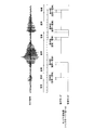
- FIG. 1 shows the determination result when the BGM signal, the signal component of each frame (speech or music), and the hangover value is 2 (that is, 2 frames forcibly use the previous determination result).
- the determination result is not switched immediately because there is a hangover. For this reason, there is a problem that an erroneous determination occurs and the sound quality deteriorates.
- An object of the present invention is to provide an encoding device and an encoding method that improve the accuracy of voice / music determination for a BGM signal and suppress deterioration in sound quality.
- the encoding apparatus includes a processing delay determining unit that determines a delay time allowed for encoding processing of an input signal, and determines whether the input signal is in a voice signal or music signal mode for each predetermined section. Comparing the mode of the previous section and the mode of the current section determined by the mode determination means, the mode determination means for performing, the hangover length determination means for determining the hangover length according to the delay time, and the comparison And a hangover means for determining the mode of the current section using the result and the hangover length, and an encoding means for encoding the input signal by an encoding method according to the determined mode. Take the configuration.
- the encoding method of the present invention includes a processing delay determination step for determining a delay time allowed for encoding processing of an input signal, and determines whether the input signal is in a voice signal mode or a music signal mode for each predetermined section. Comparing the mode determination step, the hangover length determination step for determining the hangover length according to the delay time, the mode of the previous section determined in the mode determination step and the mode of the current section, and the comparison And a hangover step for determining the mode of the current section using the hangover length and an encoding step for encoding the input signal by an encoding method according to the determined mode. I did it.
- the present invention it is possible to improve the accuracy of voice / music determination for a BGM signal and suppress deterioration in sound quality.
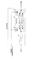
- FIG. 1 is a block diagram showing a configuration of an encoding apparatus according to Embodiment 1 of the present invention.
- the block diagram which shows the internal structure of the input signal determination part shown in FIG. Diagram showing correspondence between energy information and hangover length The block diagram which shows the internal structure of the hangover part shown in FIG.
- the flowchart which shows the process sequence of the process delay determination part shown in FIG.
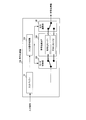
- FIG. 2 is a block diagram showing a configuration of coding apparatus 100 according to Embodiment 1 of the present invention.
- the configuration of the encoding apparatus 100 will be described with reference to FIG.
- the input buffer 101 outputs the input signal to the input signal determination unit 102, temporarily stores the input signal, and outputs it to the mode switching unit 103.
- the input signal determination unit 102 determines whether the input signal output from the input buffer 101 is an audio signal or a music signal, and outputs the determination result to the mode switching unit 103 and the output selection unit 105 as mode information. Note that. Details of the input signal determination unit 102 will be described later.
- the mode switching unit 103 Based on the mode information output from the input signal determination unit 102, the mode switching unit 103 connects the changeover switch to the encoding mode 1 or the encoding mode 2 of the encoding unit core 104, and is output from the input buffer 101. The input signal is output to encoding mode 1 or encoding mode 2 connected. Specifically, the mode switching unit 103 connects the changeover switch to the encoding mode 1 when the mode information indicates an audio signal, and sets the changeover switch to the encoding mode when the mode information indicates a music signal. Connect to 2.
- the encoding unit core 104 includes encoding modes 1 and 2, and the encoding mode 1 is, for example, G.
- the encoding mode 2 is an encoding method suitable for a music signal such as MP3 (MPEG Audio Layer-3) or AAC (Advanced Audio Coding).
- the encoding unit core 104 encodes the input signal output from the input buffer 101 in the encoding mode 1 or the encoding mode 2, and outputs the encoded information to the output selection unit 105.
- information indicating which one of the encoding mode 1 and the encoding mode 2 is used for encoding may be output as part of the encoding information. In this case, the decoding process can be performed only from the encoded information.
- the output selection unit 105 Based on the mode information output from the input signal determination unit 102, the output selection unit 105 connects to the encoding mode 1 or the encoding mode 2 of the encoding unit core 104, and from the encoding mode 1 or the encoding mode 2 The output encoded information is set as an output of the encoding apparatus 100.
- FIG. 3 is a block diagram showing an internal configuration of the input signal determination unit 102 shown in FIG.
- the internal configuration of the input signal determination unit 102 will be described with reference to FIG.
- an input signal (framed input signal) divided by a predetermined time length is input to the mode determination unit 201 and the energy calculation unit 202.
- the mode determination unit 201 analyzes an input signal using an existing method to calculate a feature parameter, and determines whether the input signal is in a voice signal or music signal mode using the feature parameter.
- the mode determination unit 201 outputs a determination result (mode information) to the energy calculation unit 202 and the hangover unit 204.
- the energy calculation unit 202 calculates the average energy (or energy information) of the input signal included in the frame determined by the mode determination unit 201 as the music signal, and outputs the energy information to the hangover length determination unit 203.
- the following processing is performed.
- the energy calculation unit 202 has a buffer for storing the average energy of past frames determined as music signals, and when the current frame is determined as a music signal, the energy calculation unit 202 stores the energy of the current frame in the buffer. Update the stored value. The update is performed according to the following equation (1).
- E avg represents the average energy of past frames determined to be music signals stored in the buffer.
- E n represents the energy of the signal current frame is included in the current frame when it is determined that the music signal.
- the energy calculation unit 202 outputs the average energy E avg calculated in this way to the hangover length determination unit 203 as energy information.
- the hangover length determination unit 203 compares the energy information output from the energy calculation unit 202 with a predetermined threshold, and if the energy information is larger than the threshold, the hangover length is increased and output to the hangover unit 204. To do. On the other hand, when the energy information is smaller than the threshold value, the hangover length determination unit 203 shortens the hangover length and outputs it to the hangover unit 204.
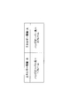
- the hangover length As a specific value of the hangover length, for example, as shown in FIG. 4, when the energy information is large, the hangover length is 2 frames. When the energy information is small, the hangover length is 1 frame. And so on.
- the hangover unit 204 stores the mode information determined in the previous frame, the mode information of the previous frame, the mode information of the current frame output from the mode determination unit 201, and the hangover length determination unit 203.
- the mode information of the current frame output from the mode determination unit 201 is determined and output using the hangover length.
- FIG. 5 is a block diagram showing an internal configuration of the hangover unit 204 shown in FIG.
- the storage unit 301 stores the mode information output from the hangover unit 204 in the previous frame, and the mode information of the previous frame is output to the determination unit 302.
- the determination unit 302 compares the mode information of the previous frame output from the storage unit 301 with the mode information of the current frame output from the mode determination unit 201.
- the counter built in the determination unit 302 is reset to zero, and the switches 303 and 304 are switched so that the path (B) becomes valid.
- the path (B) is a path for outputting the mode information output from the mode determination unit 201 as it is. For this reason, the mode information output from the mode determination unit 201 is output from the hangover unit 204 without any processing.
- the determination unit 302 compares the counter value with the hangover length output from the hangover length determination unit 203. When the counter value is equal to or smaller than the hangover length, the determination unit 302 switches the switches 303 and 304 so that the hangover process is valid, that is, the path (A) is valid.
- the path (A) is a path in which mode information output from the mode determination unit 201 is corrected by the mode information correction unit 305 and output from the hangover unit 204. If the counter value exceeds the hangover length, the determination unit 302 resets the counter to zero and switches the switches 303 and 304 so that the path (B) is valid.
- the mode information correction unit 305 operates only when the path (A) is valid, replaces the mode information output from the mode determination unit 201 with the mode information of the previous frame stored in the storage unit 301, and outputs it. .
- the mode information of the current frame that is output from the hangover unit 204 through the path (A) or the path (B) is stored in the storage unit 301, thereby replacing the mode information that has been stored so far. Prepare for the processing of the next frame.
- FIG. 6 is a diagram illustrating the effect of the encoding device 100 described above.
- the same BGM signal as in FIG. 1 is input.
- the hangover length is fixed to 2
- the energy information calculated by the energy calculation unit 202 is obtained from the threshold value. For this reason, the state when the hangover length is 1 is shown.
- the hangover length is shortened so that the voice / music determination can be performed in a short section. It is possible to improve the accuracy of voice / music determination with respect to the BGM signal and suppress deterioration in sound quality.
- the audio signal is usually used in conversation with the other party, that is, in bidirectional communication. Therefore, since the conversation does not hold when the delay becomes long, it is necessary to encode the audio signal with a short delay (hereinafter referred to as “low delay”).
- the sound signal has a characteristic that the characteristics of the signal greatly change in a relatively short time, such as a silent interval, an unvoiced interval, and a voiced interval. Therefore, even if a long time signal is stored in the encoding buffer (that is, a long delay (hereinafter referred to as “high delay”)) and analyzed, the encoding efficiency is unlikely to be high. For this reason, low delay is suitable for encoding audio signals.
- the signal characteristics of a music signal rarely change significantly in a short time like an audio signal. For this reason, encoding efficiency is greatly improved by storing and analyzing a long time signal in the encoding analysis buffer.
- a streaming signal for transmitting data in one direction from a server to a terminal is a main application, a one-way communication is less demanding on delay than two-way communication. For this reason, it can be said that high delay is suitable for encoding music signals.
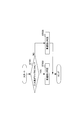
- FIG. 7 is a block diagram showing a configuration of coding apparatus 400 according to Embodiment 2 of the present invention.
- the configuration of encoding apparatus 400 will be described with reference to FIG.
- the user interface 401 is, for example, a keyboard, a touch panel, or the like, and an input source, that is, an input source switching signal for switching the ON operation of the microphone 402 and the data storage unit 403 to the microphone 402, the data storage unit 403, and the input source specifying unit 404. Output.
- the microphone 402 inputs sound according to the input source switching signal output from the user interface 401, converts the input sound into a sound signal, and outputs the sound signal to the encoding unit 406.
- the data storage unit 403 stores data such as a holding tone or a message, and outputs the stored data to the encoding unit 406 in accordance with the input source switching signal output from the user interface 401.
- the input source specifying unit 404 specifies an input source based on the input source switching signal output from the user interface 401, and outputs input source information indicating the specified input source to the processing delay determination unit 405.
- the processing delay determination unit 405 determines a delay time allowed for the encoding process according to the input source information output from the input source specifying unit 404. Specifically, as shown in FIG. 8, when the input source is a microphone (ST501: YES), the processing delay determination unit 405 determines that the data to be encoded is bidirectional, such as a voice call. It is determined that the data requires real-time processing, and the processing delay is determined to be low delay (ST502). On the other hand, when the input source is the data storage unit 403 (ST501: NO), the processing delay determination unit 405 does not need the bidirectional real-time processing such as hold tone or message for the data to be encoded. It is determined that the data is data, and the processing delay is determined to be a high delay (ST503). The processing delay determination unit 405 outputs the determination result (delay information) to the encoding unit 406.
- the encoding unit 406 Based on the delay information output from the processing delay determination unit 405, the encoding unit 406 converts the audio signal output from the microphone 402 or the data output from the data storage unit 403 by an encoding method suitable for each characteristic. Encode and output encoded information.
- FIG. 9 is a block diagram showing an internal configuration of the encoding unit 406 shown in FIG.
- the internal configuration of the encoding unit 406 will be described with reference to FIG.
- the encoding unit 406 in FIG. 9 deletes the input signal determination unit 102 from the encoding device 100 in FIG. 2, changes the mode switching unit 103 to the mode switching unit 601, and outputs the output selection unit 105. The difference is that the selection unit 602 is changed.
- the mode switching unit 601 Based on the delay information output from the processing delay determination unit 405, the mode switching unit 601 connects the changeover switch to the encoding mode 1 or the encoding mode 2 of the encoding unit core 104 and is output from the input buffer 101.
- the input signal is output to encoding mode 1 or encoding mode 2 connected.
- the mode switching unit 601 connects to the encoding mode 1 when the delay information indicates a low delay, and connects to the encoding mode 2 when the delay information indicates a high delay.
- the encoding mode 1 is, for example, G.
- the encoding mode 2 is an encoding method suitable for an audio signal such as 729, and the encoding mode 2 is an encoding method suitable for a music signal such as MP3 or AAC.
- the output selection unit 602 Based on the delay information output from the processing delay determination unit 405, the output selection unit 602 connects to the encoding mode 1 or the encoding mode 2 of the encoding unit core 104, and from the encoding mode 1 or the encoding mode 2 The output encoded information is set as an output of the encoding apparatus 400.
- the processing delay allowed for the encoding process is determined according to the input source, and the input signal is switched by changing the encoding method according to the delay information indicating the determination result.
- the hangover length is controlled according to the energy information of the input signal.
- the hangover length may be controlled according to the processing delay allowed for the encoding process. Good.
- the input signal can be stored in the buffer for a long time, so future data can be referenced. For this reason, the voice / music determination performance itself is improved. In this case, a long hangover is unnecessary, and the hangover length is shortened. As a result, it is possible to avoid deterioration in sound quality due to hangover and improve the overall sound quality.
- the hangover length may be increased when the frame length of the encoding method is short (for example, 10 msec or less), or when speech / music determination performance is poor because noise is superimposed on the input signal. Further, when the frame length of the encoding method is long (for example, 40 msec or more), the hangover length may be shortened.
- each functional block used in the description of each of the above embodiments is typically realized as an LSI which is an integrated circuit. These may be individually made into one chip, or may be made into one chip so as to include a part or all of them.
- the name used here is LSI, but it may also be called IC, system LSI, super LSI, or ultra LSI depending on the degree of integration.
- the method of circuit integration is not limited to LSI, and may be realized by a dedicated circuit or a general-purpose processor.
- An FPGA Field Programmable Gate Array
- a reconfigurable processor that can reconfigure the connection and setting of circuit cells inside the LSI may be used.
- the encoding device and the encoding method according to the present invention can be applied to a communication terminal such as a mobile phone having a call function, for example.
Abstract
Provided are an encoding device and encoding method capable of improving the accuracy of determining whether a BGM signal is in a voice signal mode or a music signal mode and minimizing degradation in sound quality. A mode determination unit (201) determines whether an input signal is in a voice signal mode or music signal mode, and an energy calculation unit (202) calculates the average energy of the input signal included in a frame determined to be a music signal. A hangover length determination unit (203) increases the hangover length when the amount of calculated energy information is large, and decreases the hangover length when the amount of calculated energy information is small. A hangover unit (204) uses the mode information of the previous frame, the mode information of the present frame, and the determined hangover length and corrects the mode information for the present frame when a prescribed condition is satisfied.
Description
本発明は、音声信号及び音楽信号を符号化する符号化装置及び符号化方法に関する。
The present invention relates to an encoding device and an encoding method for encoding an audio signal and a music signal.
現在、3GPP(3rd Generation Partnership Project)において、EPS(Evolved Packet System)に適した音声コーデックであるEVS(Enhanced Voice Service)の標準化が行われている。非特許文献1には、EVSに対する要求条件が、近年の携帯端末を用いた通話サービスを意識して決められている。例えば、携帯端末の保留音が音楽付き音声であること、または、コールセンターからのBGM付き音声案内を携帯端末で聞きながら処理することを想定しているため、音楽も良い品質で再生することが求められている。
Currently, 3GPP (3rd Generation Partnership Project) is standardizing EVS (Enhanced Voice Service), which is a speech codec suitable for EPS (Evolved Packet System). In Non-Patent Document 1, the requirements for EVS are determined in consideration of recent telephone service using portable terminals. For example, it is assumed that the hold sound of the mobile terminal is a voice with music, or the voice guidance with BGM from the call center is processed while listening to the mobile terminal, so the music is also required to be reproduced with good quality. It has been.
音楽を良い品質で再生する技術として、特許文献1には、VSELP(Vector Sum Excited Linear Prediction)を用いた携帯端末において、保留が指示された際にはVOX(Voice Operated Transmission)制御をオフにする方法が開示されている。また、特許文献2には、携帯端末へ音楽を提供する場合に、同時に送出する周波数の数である和音数の異なる複数の音源ファイルを携帯端末が予め蓄積しておき、使用するコーデックに応じた音源ファイルを選択する方法が開示されている。
As a technique for reproducing music with good quality, Patent Document 1 discloses that VOX (Voice Operated Transmission) control is turned off when a hold is instructed in a portable terminal using VSELP (Vector Sum Excited Linear Prediction). A method is disclosed. Also, in Patent Document 2, when music is provided to a mobile terminal, the mobile terminal stores in advance a plurality of sound source files having different numbers of chords, which are the number of frequencies to be transmitted simultaneously, according to the codec used. A method for selecting a sound source file is disclosed.
また、音声信号の符号化に適するよう設計された音声符号化部と、音楽信号の符号化に適するよう設計された音楽符号化部とを、入力信号に応じてフレーム単位で切り替える技術は、非特許文献2に開示の音声/音楽汎用符号化方式(USAC: Unified Speech and Audio Coding)に代表されるように、音声信号及び音楽信号を高音質に符号化できる有望な技術として知られている。このとき、フレーム単位で符号化方式を切り替えるため、切り替え方法の性能が音質に与える影響が大きい。なお、フレーム長は、符号化方式によって異なるが、多くの場合20msecが用いられている。
In addition, a technology for switching between a speech encoding unit designed to be suitable for encoding a speech signal and a music encoding unit designed to be suitable for encoding a music signal in units of frames according to an input signal is not available. As represented by the speech / music universal coding system (USAC: “Unified Speech and Audio Audio Coding” disclosed in Patent Document 2, it is known as a promising technique capable of encoding speech signals and music signals with high sound quality. At this time, since the coding method is switched in units of frames, the performance of the switching method has a great influence on the sound quality. Although the frame length varies depending on the encoding method, in many cases, 20 msec is used.
一方で、音声/音楽の判定をフレーム単位で行う方式がG.720.1(または、GSAD: Generic Sound Activity Detector)としてITU-Tにて標準化されている(非特許文献3参照)。GSADでは、フレーム単位に特徴パラメータを使って音声/音楽の判定を行うが、判定結果が不安定となり、音声/音楽の頻繁な切り替えが生じてしまう場合がある。このような頻繁な切り替えを避けるため、ハングオーバーと呼ばれる技術が適用される。ハングオーバーとは、前フレームで選択された判定結果を規定回数だけ強制的に使用する技術であり、これにより頻繁な切り替えを避けることが可能となる。
On the other hand, G. is a method for performing voice / music determination in units of frames. It is standardized by ITU-T as 720.1 (or GSAD: “Generic Sound Activity Detector”) (see Non-Patent Document 3). In GSAD, voice / music determination is performed using feature parameters for each frame, but the determination result becomes unstable, and frequent switching between voice / music may occur. In order to avoid such frequent switching, a technique called hangover is applied. Hangover is a technique for forcibly using the determination result selected in the previous frame a specified number of times, and thus frequent switching can be avoided.
ハングオーバーは、音声/音楽の頻繁な切り替えを避けるために有効な技術であるが、音楽が背景で流れている環境で音声通話を行う場合に問題がある。以後、このような信号をBGM信号と呼ぶ。BGM信号は、非音声区間では音楽が流れており、音声区間では音声に音楽が重畳している。
Hangover is an effective technique for avoiding frequent voice / music switching, but there is a problem when making a voice call in an environment where music is flowing in the background. Hereinafter, such a signal is referred to as a BGM signal. In the BGM signal, music flows in the non-voice section, and music is superimposed on the voice in the voice section.
図1にBGM信号、各フレームの信号成分(音声または音楽)、ハングオーバー値が2(すなわち、2フレームは前回の判定結果を強制的に使用)の場合における判定結果を示す。図1に示すように、信号成分が切り替わるときに、ハングオーバーがあるために、すぐには判定結果が切り替わらない。そのため誤判定となってしまい、音質が劣化するという問題がある。
FIG. 1 shows the determination result when the BGM signal, the signal component of each frame (speech or music), and the hangover value is 2 (that is, 2 frames forcibly use the previous determination result). As shown in FIG. 1, when the signal component is switched, the determination result is not switched immediately because there is a hangover. For this reason, there is a problem that an erroneous determination occurs and the sound quality deteriorates.
この現象は、例えば、背景が無音の場合(クリーン信号)、及び背景雑音がなっている場合(背景雑音信号)には、通常、音声と判定されるため、問題とはならない。このように、音楽が背景で流れている場合に音楽と判定してしまうため、上述したハングオーバーの問題はBGM信号特有のものである。
This phenomenon is not a problem because, for example, when the background is silent (clean signal) and when background noise is present (background noise signal), it is usually determined as speech. Thus, since music is determined as music when it is flowing in the background, the above-described hangover problem is peculiar to the BGM signal.
本発明の目的は、BGM信号に対する音声/音楽判定の精度を向上させ、音質劣化を抑制する符号化装置及び符号化方法を提供することである。
An object of the present invention is to provide an encoding device and an encoding method that improve the accuracy of voice / music determination for a BGM signal and suppress deterioration in sound quality.
本発明の符号化装置は、入力信号の符号化処理に許容される遅延時間を判定する処理遅延判定手段と、前記入力信号が音声信号又は音楽信号のいずれのモードかを所定の区間毎に判定するモード判定手段と、前記遅延時間に応じて、ハングオーバー長を決定するハングオーバー長決定手段と、前記モード判定手段によって判定された前区間のモードと現区間のモードとを比較し、前記比較の結果及び前記ハングオーバー長を用いて、前記現区間のモードを確定するハングオーバー手段と、確定されたモードに応じた符号化方式によって前記入力信号を符号化する符号化手段と、を具備する構成を採る。
The encoding apparatus according to the present invention includes a processing delay determining unit that determines a delay time allowed for encoding processing of an input signal, and determines whether the input signal is in a voice signal or music signal mode for each predetermined section. Comparing the mode of the previous section and the mode of the current section determined by the mode determination means, the mode determination means for performing, the hangover length determination means for determining the hangover length according to the delay time, and the comparison And a hangover means for determining the mode of the current section using the result and the hangover length, and an encoding means for encoding the input signal by an encoding method according to the determined mode. Take the configuration.
本発明の符号化方法は、入力信号の符号化処理に許容される遅延時間を判定する処理遅延判定工程と、前記入力信号が音声信号又は音楽信号のいずれのモードかを所定の区間毎に判定するモード判定工程と、前記遅延時間に応じて、ハングオーバー長を決定するハングオーバー長決定工程と、前記モード判定工程において判定された前区間のモードと現区間のモードとを比較し、前記比較の結果及び前記ハングオーバー長を用いて、前記現区間のモードを確定するハングオーバー工程と、確定されたモードに応じた符号化方式によって前記入力信号を符号化する符号化工程と、を具備するようにした。
The encoding method of the present invention includes a processing delay determination step for determining a delay time allowed for encoding processing of an input signal, and determines whether the input signal is in a voice signal mode or a music signal mode for each predetermined section. Comparing the mode determination step, the hangover length determination step for determining the hangover length according to the delay time, the mode of the previous section determined in the mode determination step and the mode of the current section, and the comparison And a hangover step for determining the mode of the current section using the hangover length and an encoding step for encoding the input signal by an encoding method according to the determined mode. I did it.
本発明によれば、BGM信号に対する音声/音楽判定の精度を向上させ、音質劣化を抑制することができる。
According to the present invention, it is possible to improve the accuracy of voice / music determination for a BGM signal and suppress deterioration in sound quality.
以下、本発明の実施の形態について、図面を参照して詳細に説明する。ただし、実施の形態において、同一機能を有する構成には、同一符号を付し、重複する説明は省略する。
Hereinafter, embodiments of the present invention will be described in detail with reference to the drawings. However, in the embodiment, components having the same function are denoted by the same reference numerals, and redundant description is omitted.
(実施の形態1)
図2は、本発明の実施の形態1に係る符号化装置100の構成を示すブロック図である。以下、符号化装置100の構成について図2を用いて説明する。 (Embodiment 1)
FIG. 2 is a block diagram showing a configuration of coding apparatus 100 according to Embodiment 1 of the present invention. Hereinafter, the configuration of the encoding apparatus 100 will be described with reference to FIG.
入力バッファ101は、入力信号を入力信号判定部102に出力すると共に、入力信号を一時記憶して、モード切替部103に出力する。
The input buffer 101 outputs the input signal to the input signal determination unit 102, temporarily stores the input signal, and outputs it to the mode switching unit 103.
入力信号判定部102は、入力バッファ101から出力された入力信号が音声信号か音楽信号かを判定し、判定結果をモード情報としてモード切替部103及び出力選択部105に出力する。なお。入力信号判定部102の詳細については後述する。
The input signal determination unit 102 determines whether the input signal output from the input buffer 101 is an audio signal or a music signal, and outputs the determination result to the mode switching unit 103 and the output selection unit 105 as mode information. Note that. Details of the input signal determination unit 102 will be described later.
モード切替部103は、入力信号判定部102から出力されたモード情報に基づいて、切替スイッチを符号化部コア104の符号化モード1又は符号化モード2に接続し、入力バッファ101から出力された入力信号を接続した符号化モード1または符号化モード2に出力する。具体的には、モード切替部103は、モード情報が音声信号を示す場合には、切替スイッチを符号化モード1に接続し、モード情報が音楽信号を示す場合には、切替スイッチを符号化モード2に接続する。
Based on the mode information output from the input signal determination unit 102, the mode switching unit 103 connects the changeover switch to the encoding mode 1 or the encoding mode 2 of the encoding unit core 104, and is output from the input buffer 101. The input signal is output to encoding mode 1 or encoding mode 2 connected. Specifically, the mode switching unit 103 connects the changeover switch to the encoding mode 1 when the mode information indicates an audio signal, and sets the changeover switch to the encoding mode when the mode information indicates a music signal. Connect to 2.
符号化部コア104は、符号化モード1と符号化モード2の符号化方式を備え、符号化モード1は、例えば、G.729などの音声信号に適した符号化方式であり、符号化モード2は、例えば、MP3(MPEG Audio Layer-3)またはAAC(Advanced Audio Coding)などの音楽信号に適した符号化方式である。符号化部コア104は、入力バッファ101から出力された入力信号を符号化モード1または符号化モード2によって符号化し、符号化情報を出力選択部105に出力する。なお、符号化モード1と符号化モード2のいずれを用いて符号化したかを示す情報も符号化情報の一部として出力してもよい。この場合、符号化情報のみから復号処理が可能である。
The encoding unit core 104 includes encoding modes 1 and 2, and the encoding mode 1 is, for example, G. The encoding mode 2 is an encoding method suitable for a music signal such as MP3 (MPEG Audio Layer-3) or AAC (Advanced Audio Coding). The encoding unit core 104 encodes the input signal output from the input buffer 101 in the encoding mode 1 or the encoding mode 2, and outputs the encoded information to the output selection unit 105. Note that information indicating which one of the encoding mode 1 and the encoding mode 2 is used for encoding may be output as part of the encoding information. In this case, the decoding process can be performed only from the encoded information.
出力選択部105は、入力信号判定部102から出力されたモード情報に基づいて、符号化部コア104の符号化モード1又は符号化モード2に接続し、符号化モード1又は符号化モード2から出力された符号化情報を符号化装置100の出力とする。
Based on the mode information output from the input signal determination unit 102, the output selection unit 105 connects to the encoding mode 1 or the encoding mode 2 of the encoding unit core 104, and from the encoding mode 1 or the encoding mode 2 The output encoded information is set as an output of the encoding apparatus 100.
図3は、図2に示した入力信号判定部102の内部構成を示すブロック図である。以下、入力信号判定部102の内部構成について図3を用いて説明する。図3において、予め定められた時間長によって区切られた入力信号(フレーム化された入力信号)がモード判定部201及びエネルギー算出部202に入力される。
FIG. 3 is a block diagram showing an internal configuration of the input signal determination unit 102 shown in FIG. Hereinafter, the internal configuration of the input signal determination unit 102 will be described with reference to FIG. In FIG. 3, an input signal (framed input signal) divided by a predetermined time length is input to the mode determination unit 201 and the energy calculation unit 202.
モード判定部201は、既存の手法により入力信号の分析を行って特徴パラメータを算出し、特徴パラメータを用いて入力信号が音声信号又は音楽信号のいずれのモードかを判定する。モード判定部201は、判定結果(モード情報)をエネルギー算出部202及びハングオーバー部204に出力する。
The mode determination unit 201 analyzes an input signal using an existing method to calculate a feature parameter, and determines whether the input signal is in a voice signal or music signal mode using the feature parameter. The mode determination unit 201 outputs a determination result (mode information) to the energy calculation unit 202 and the hangover unit 204.
エネルギー算出部202は、モード判定部201において音楽信号と判定されたフレームに含まれる入力信号の平均エネルギー(またはエネルギー情報)を算出し、エネルギー情報をハングオーバー長決定部203に出力する。エネルギー情報の算出方法としては、例えば、次のような処理を行う。
The energy calculation unit 202 calculates the average energy (or energy information) of the input signal included in the frame determined by the mode determination unit 201 as the music signal, and outputs the energy information to the hangover length determination unit 203. As a method for calculating energy information, for example, the following processing is performed.
エネルギー算出部202は、音楽信号と判定された過去のフレームの平均エネルギーを記憶するバッファを有し、現フレームが音楽信号と判定されたときに、現フレームのエネルギーを反映するように、バッファに記憶されている値を更新する。更新は次の式(1)に従って行われる。

The energy calculation unit 202 has a buffer for storing the average energy of past frames determined as music signals, and when the current frame is determined as a music signal, the energy calculation unit 202 stores the energy of the current frame in the buffer. Update the stored value. The update is performed according to the following equation (1).
ここで、Eavgは、バッファに記憶されている音楽信号と判定された過去のフレームの平均エネルギーを表す。また、Enは、現フレームが音楽信号と判定されたときの現フレームに含まれる信号のエネルギーを表す。さらに、αは、更新速度を制御する0以上1未満の係数を表し、例えばα=0.95などの数値を用いる。現フレームが音声信号と判定された場合には、このバッファの更新は行われない。これにより、音楽信号の平均的なエネルギーを算出することができる。
Here, E avg represents the average energy of past frames determined to be music signals stored in the buffer. Also, E n represents the energy of the signal current frame is included in the current frame when it is determined that the music signal. Furthermore, α represents a coefficient that is greater than or equal to 0 and less than 1 that controls the update rate, and a numerical value such as α = 0.95 is used, for example. If it is determined that the current frame is an audio signal, the buffer is not updated. Thereby, the average energy of the music signal can be calculated.
エネルギー算出部202は、このように算出した平均エネルギーEavgをエネルギー情報として、ハングオーバー長決定部203に出力する。
The energy calculation unit 202 outputs the average energy E avg calculated in this way to the hangover length determination unit 203 as energy information.
ハングオーバー長決定部203は、エネルギー算出部202から出力されたエネルギー情報と所定の閾値とを比較し、エネルギー情報が閾値より大きい場合には、ハングオーバー長を長くしてハングオーバー部204に出力する。一方、エネルギー情報が閾値より小さい場合には、ハングオーバー長決定部203は、ハングオーバー長を短くしてハングオーバー部204に出力する。ハングオーバー長の具体的な値としては、例えば、図4に示すように、エネルギー情報が大きい場合には、ハングオーバー長を2フレームとし、エネルギー情報が小さい場合には、ハングオーバー長を1フレームなどとする。
The hangover length determination unit 203 compares the energy information output from the energy calculation unit 202 with a predetermined threshold, and if the energy information is larger than the threshold, the hangover length is increased and output to the hangover unit 204. To do. On the other hand, when the energy information is smaller than the threshold value, the hangover length determination unit 203 shortens the hangover length and outputs it to the hangover unit 204. As a specific value of the hangover length, for example, as shown in FIG. 4, when the energy information is large, the hangover length is 2 frames. When the energy information is small, the hangover length is 1 frame. And so on.
このように、BGM信号における非音声区間の音楽信号のエネルギー情報が小さい場合には、音声/音楽判定の誤判定が起きにくく、判定の精度が向上するため、ハングオーバー長を短くしても、ハングオーバーに起因する音声/音楽判定の誤判定を低減することができる。一方、BGM信号における音声区間(音声信号)のエネルギー情報が大きい場合には、音声/音楽判定の誤判定が起こりやすく、判定の精度が劣化するため、ハングオーバー長を長くすることにより、音声/音楽判定の誤判定を低減することができる。
As described above, when the energy information of the music signal in the non-speech section in the BGM signal is small, erroneous determination of the voice / music determination is less likely to occur, and the determination accuracy is improved. It is possible to reduce erroneous voice / music judgment due to hangover. On the other hand, when the energy information of the voice section (voice signal) in the BGM signal is large, erroneous determination of voice / music determination is likely to occur, and the accuracy of the determination deteriorates. Therefore, by increasing the hangover length, Misjudgment of music judgment can be reduced.
ハングオーバー部204は、前フレームで決定したモード情報を記憶しており、前フレームのモード情報と、モード判定部201から出力された現フレームのモード情報と、ハングオーバー長決定部203から出力されたハングオーバー長とを用いて、モード判定部201から出力された現フレームのモード情報を確定して出力する。
The hangover unit 204 stores the mode information determined in the previous frame, the mode information of the previous frame, the mode information of the current frame output from the mode determination unit 201, and the hangover length determination unit 203. The mode information of the current frame output from the mode determination unit 201 is determined and output using the hangover length.
図5は、図3に示したハングオーバー部204の内部構成を示すブロック図である。以下、ハングオーバー部204の内部構成について図5を用いて説明する。記憶部301には、前フレームにてハングオーバー部204から出力されたモード情報が記憶されており、前フレームのモード情報が判定部302に出力される。
FIG. 5 is a block diagram showing an internal configuration of the hangover unit 204 shown in FIG. Hereinafter, the internal configuration of the hangover unit 204 will be described with reference to FIG. The storage unit 301 stores the mode information output from the hangover unit 204 in the previous frame, and the mode information of the previous frame is output to the determination unit 302.
判定部302は、記憶部301から出力された前フレームのモード情報と、モード判定部201から出力された現フレームのモード情報とを比較する。前フレームのモード情報と現フレームのモード情報とが一致する場合、判定部302に内蔵されているカウンタをゼロにリセットし、パス(B)が有効となるようにスイッチ303、304を切り替える。パス(B)は、モード判定部201から出力されたモード情報をそのまま出力する経路である。このため、モード判定部201から出力されたモード情報は、何ら処理されることなくハングオーバー部204から出力される。
The determination unit 302 compares the mode information of the previous frame output from the storage unit 301 with the mode information of the current frame output from the mode determination unit 201. When the mode information of the previous frame matches the mode information of the current frame, the counter built in the determination unit 302 is reset to zero, and the switches 303 and 304 are switched so that the path (B) becomes valid. The path (B) is a path for outputting the mode information output from the mode determination unit 201 as it is. For this reason, the mode information output from the mode determination unit 201 is output from the hangover unit 204 without any processing.
一方、前フレームのモード情報と現フレームのモード情報とが一致しない場合、判定部302に内蔵されているカウンタをインクリメントする。判定部302は、カウンタ値とハングオーバー長決定部203から出力されたハングオーバー長とを比較する。カウンタ値がハングオーバー長以下の場合、判定部302は、ハングオーバー処理が有効、すなわち、パス(A)が有効となるようにスイッチ303、304を切り替える。パス(A)は、モード判定部201から出力されたモード情報をモード情報修正部305において修正して、ハングオーバー部204から出力する経路である。また、カウンタ値がハングオーバー長を超えている場合、判定部302は、カウンタをゼロにリセットすると共に、パス(B)が有効となるようにスイッチ303、304を切り替える。
On the other hand, if the mode information of the previous frame does not match the mode information of the current frame, the counter built in the determination unit 302 is incremented. The determination unit 302 compares the counter value with the hangover length output from the hangover length determination unit 203. When the counter value is equal to or smaller than the hangover length, the determination unit 302 switches the switches 303 and 304 so that the hangover process is valid, that is, the path (A) is valid. The path (A) is a path in which mode information output from the mode determination unit 201 is corrected by the mode information correction unit 305 and output from the hangover unit 204. If the counter value exceeds the hangover length, the determination unit 302 resets the counter to zero and switches the switches 303 and 304 so that the path (B) is valid.
モード情報修正部305は、パス(A)が有効なときにのみ動作し、モード判定部201から出力されたモード情報を、記憶部301に記憶されている前フレームのモード情報に置き換え、出力する。
The mode information correction unit 305 operates only when the path (A) is valid, replaces the mode information output from the mode determination unit 201 with the mode information of the previous frame stored in the storage unit 301, and outputs it. .
パス(A)またはパス(B)を通過してハングオーバー部204から出力される現フレームのモード情報は、記憶部301に記憶されることにより、それまで記憶されていたモード情報と置き換えられ、次のフレームの処理に備える。
The mode information of the current frame that is output from the hangover unit 204 through the path (A) or the path (B) is stored in the storage unit 301, thereby replacing the mode information that has been stored so far. Prepare for the processing of the next frame.
図6は、上述した符号化装置100の効果を示す図である。図6では、図1と同一のBGM信号が入力されており、図1ではハングオーバー長が2と固定されているのに対し、図6ではエネルギー算出部202で算出されたエネルギー情報が閾値より小さく、そのため、ハングオーバー長を1としたときの様子を示している。
FIG. 6 is a diagram illustrating the effect of the encoding device 100 described above. In FIG. 6, the same BGM signal as in FIG. 1 is input. In FIG. 1, the hangover length is fixed to 2, whereas in FIG. 6, the energy information calculated by the energy calculation unit 202 is obtained from the threshold value. For this reason, the state when the hangover length is 1 is shown.
図6から分かるように、ハングオーバーに起因する誤判定の長さが、図1に比べて半分になっている。このため、上述した符号化装置100では音質を改善することが可能となる。
As can be seen from FIG. 6, the length of misjudgment caused by hangover is half that of FIG. For this reason, it is possible to improve the sound quality in the encoding apparatus 100 described above.
このように、実施の形態1によれば、入力信号のエネルギーを算出し、算出したエネルギーが小さい場合に、ハングオーバー長を短くすることにより、音声/音楽判定を短い区間で行うことができ、BGM信号に対する音声/音楽判定の精度を向上させ、音質劣化を抑制することができる。
As described above, according to the first embodiment, when the energy of the input signal is calculated and the calculated energy is small, the hangover length is shortened so that the voice / music determination can be performed in a short section. It is possible to improve the accuracy of voice / music determination with respect to the BGM signal and suppress deterioration in sound quality.
(実施の形態2)
音声信号は、通常、相手との会話、すなわち双方向通信にて使用される。そのため、遅延が長くなると会話が成り立たなくなるので、音声信号を短い遅延(以下、「低遅延」という)で符号化する必要がある。また、音声信号は、無音区間、無声区間及び有声区間というように、比較的短時間に信号の特性が大きく変わるという特徴がある。このため、符号化用のバッファに長い時間信号を格納(すなわち、長い遅延(以下、「高遅延」という))して分析しても符号化効率は高くなりにくい。このような理由により、音声信号の符号化には低遅延が向いている。 (Embodiment 2)
The audio signal is usually used in conversation with the other party, that is, in bidirectional communication. Therefore, since the conversation does not hold when the delay becomes long, it is necessary to encode the audio signal with a short delay (hereinafter referred to as “low delay”). In addition, the sound signal has a characteristic that the characteristics of the signal greatly change in a relatively short time, such as a silent interval, an unvoiced interval, and a voiced interval. Therefore, even if a long time signal is stored in the encoding buffer (that is, a long delay (hereinafter referred to as “high delay”)) and analyzed, the encoding efficiency is unlikely to be high. For this reason, low delay is suitable for encoding audio signals.
一方、音楽信号は、音声信号のように信号特性が短時間で大きく変わることは稀である。そのため、符号化用の分析バッファに長い時間信号を格納して分析することにより、符号化効率が大きく向上する。また、音楽信号は、通常、サーバーから端末に片方向にデータを伝送するストリーミングが主要なアプリケーションとなるため、片方向通信は双方向通信より遅延の要求が厳しくない。このような理由により、音楽信号の符号化には高遅延が適しているといえる。
On the other hand, the signal characteristics of a music signal rarely change significantly in a short time like an audio signal. For this reason, encoding efficiency is greatly improved by storing and analyzing a long time signal in the encoding analysis buffer. In addition, since a streaming signal for transmitting data in one direction from a server to a terminal is a main application, a one-way communication is less demanding on delay than two-way communication. For this reason, it can be said that high delay is suitable for encoding music signals.
以下、上述した音声信号と音楽信号の特徴を踏まえ、本発明の実施の形態2について説明する。図7は、本発明の実施の形態2に係る符号化装置400の構成を示すブロック図である。以下、符号化装置400の構成について図7を用いて説明する。
Hereinafter, the second embodiment of the present invention will be described based on the characteristics of the audio signal and the music signal described above. FIG. 7 is a block diagram showing a configuration of coding apparatus 400 according to Embodiment 2 of the present invention. Hereinafter, the configuration of encoding apparatus 400 will be described with reference to FIG.
ユーザインタフェース401は、例えば、キーボード、タッチパネル等であり、入力源、すなわち、マイクロフォン402及びデータ蓄積部403のON動作を切り替える入力源切替信号をマイクロフォン402、データ蓄積部403及び入力源特定部404に出力する。
The user interface 401 is, for example, a keyboard, a touch panel, or the like, and an input source, that is, an input source switching signal for switching the ON operation of the microphone 402 and the data storage unit 403 to the microphone 402, the data storage unit 403, and the input source specifying unit 404. Output.
マイクロフォン402は、ユーザインタフェース401から出力された入力源切替信号に従って、音声を入力し、入力した音声を音声信号に変換して、符号化部406に出力する。また、データ蓄積部403は、保留音又はメッセージ等のデータを蓄積し、ユーザインタフェース401から出力された入力源切替信号に従って、蓄積したデータを符号化部406に出力する。
The microphone 402 inputs sound according to the input source switching signal output from the user interface 401, converts the input sound into a sound signal, and outputs the sound signal to the encoding unit 406. In addition, the data storage unit 403 stores data such as a holding tone or a message, and outputs the stored data to the encoding unit 406 in accordance with the input source switching signal output from the user interface 401.
入力源特定部404は、ユーザインタフェース401から出力された入力源切替信号によって入力源を特定し、特定した入力源を示す入力源情報を処理遅延判定部405に出力する。
The input source specifying unit 404 specifies an input source based on the input source switching signal output from the user interface 401, and outputs input source information indicating the specified input source to the processing delay determination unit 405.
処理遅延判定部405は、入力源特定部404から出力された入力源情報に応じて、符号化処理に許容される遅延時間を判定する。具体的には、図8に示すように、入力源がマイクロフォンであった場合(ST501:YES)、処理遅延判定部405は、符号化処理の対象となるデータが、音声通話等の双方向のリアルタイム処理が必要なデータであると判断し、処理遅延を低遅延と判定する(ST502)。一方、入力源がデータ蓄積部403であった場合(ST501:NO)、処理遅延判定部405は、符号化処理の対象となるデータが、保留音またはメッセージ等の双方向リアルタイム処理の必要のないデータであると判断し、処理遅延を高遅延と判定する(ST503)。処理遅延判定部405は、判定結果(遅延情報)を符号化部406に出力する。
The processing delay determination unit 405 determines a delay time allowed for the encoding process according to the input source information output from the input source specifying unit 404. Specifically, as shown in FIG. 8, when the input source is a microphone (ST501: YES), the processing delay determination unit 405 determines that the data to be encoded is bidirectional, such as a voice call. It is determined that the data requires real-time processing, and the processing delay is determined to be low delay (ST502). On the other hand, when the input source is the data storage unit 403 (ST501: NO), the processing delay determination unit 405 does not need the bidirectional real-time processing such as hold tone or message for the data to be encoded. It is determined that the data is data, and the processing delay is determined to be a high delay (ST503). The processing delay determination unit 405 outputs the determination result (delay information) to the encoding unit 406.
符号化部406は、処理遅延判定部405から出力された遅延情報に基づいて、マイクロフォン402から出力された音声信号又はデータ蓄積部403から出力されたデータをそれぞれの特性に適した符号化方式によって符号化し、符号化情報を出力する。
Based on the delay information output from the processing delay determination unit 405, the encoding unit 406 converts the audio signal output from the microphone 402 or the data output from the data storage unit 403 by an encoding method suitable for each characteristic. Encode and output encoded information.
図9は、図7に示した符号化部406の内部構成を示すブロック図である。以下、符号化部406の内部構成について図9を用いて説明する。ただし、図9の符号化部406は、図2の符号化装置100に対して、入力信号判定部102を削除し、モード切替部103をモード切替部601に変更し、出力選択部105を出力選択部602に変更した点が異なる。
FIG. 9 is a block diagram showing an internal configuration of the encoding unit 406 shown in FIG. Hereinafter, the internal configuration of the encoding unit 406 will be described with reference to FIG. However, the encoding unit 406 in FIG. 9 deletes the input signal determination unit 102 from the encoding device 100 in FIG. 2, changes the mode switching unit 103 to the mode switching unit 601, and outputs the output selection unit 105. The difference is that the selection unit 602 is changed.
モード切替部601は、処理遅延判定部405から出力された遅延情報に基づいて、切替スイッチを符号化部コア104の符号化モード1または符号化モード2に接続し、入力バッファ101から出力された入力信号を接続した符号化モード1または符号化モード2に出力する。具体的には、モード切替部601は、遅延情報が低遅延を示す場合には、符号化モード1に接続し、遅延情報が高遅延を示す場合には、符号化モード2に接続する。なお、符号化モード1は、例えば、G.729などの音声信号に適した符号化方式であり、符号化モード2は、例えば、MP3又はAACなどの音楽信号に適した符号化方式である。
Based on the delay information output from the processing delay determination unit 405, the mode switching unit 601 connects the changeover switch to the encoding mode 1 or the encoding mode 2 of the encoding unit core 104 and is output from the input buffer 101. The input signal is output to encoding mode 1 or encoding mode 2 connected. Specifically, the mode switching unit 601 connects to the encoding mode 1 when the delay information indicates a low delay, and connects to the encoding mode 2 when the delay information indicates a high delay. The encoding mode 1 is, for example, G. The encoding mode 2 is an encoding method suitable for an audio signal such as 729, and the encoding mode 2 is an encoding method suitable for a music signal such as MP3 or AAC.
出力選択部602は、処理遅延判定部405から出力された遅延情報に基づいて、符号化部コア104の符号化モード1または符号化モード2に接続し、符号化モード1または符号化モード2から出力された符号化情報を符号化装置400の出力とする。
Based on the delay information output from the processing delay determination unit 405, the output selection unit 602 connects to the encoding mode 1 or the encoding mode 2 of the encoding unit core 104, and from the encoding mode 1 or the encoding mode 2 The output encoded information is set as an output of the encoding apparatus 400.
このように、実施の形態2によれば、入力源に応じて、符号化処理に許容される処理遅延を判定し、判定結果を示す遅延情報に応じて、符号化方式を切り替えて入力信号を符号化することにより、精度良く符号化することができ、音質劣化を抑制することができる。
As described above, according to the second embodiment, the processing delay allowed for the encoding process is determined according to the input source, and the input signal is switched by changing the encoding method according to the delay information indicating the determination result. By encoding, it is possible to encode with high accuracy and to suppress deterioration in sound quality.
なお、実施の形態1では、入力信号のエネルギー情報に応じて、ハングオーバー長を制御する場合について説明したが、符号化処理に許容される処理遅延に応じて、ハングオーバー長を制御してもよい。
In the first embodiment, the case where the hangover length is controlled according to the energy information of the input signal has been described. However, the hangover length may be controlled according to the processing delay allowed for the encoding process. Good.
高遅延では、入力信号を長い時間バッファに格納できるので、未来のデータまで参照可能である。このため、音声/音楽判定の性能自体が高くなる。この場合、長いハングオーバーは不要であり、ハングオーバー長を短くする。これにより、ハングオーバーに起因する音質劣化を回避することができ、全体的な音質を改善することができる。
• With high delay, the input signal can be stored in the buffer for a long time, so future data can be referenced. For this reason, the voice / music determination performance itself is improved. In this case, a long hangover is unnecessary, and the hangover length is shortened. As a result, it is possible to avoid deterioration in sound quality due to hangover and improve the overall sound quality.
一方、低遅延では、入力信号を短い時間しかバッファに格納できないので、未来のデータを参照することができない。このため、現在のデータしか分析に使用することができない。この場合、音声/音楽判定の判定性能が低下してしまうので、ハングオーバー長を長くし、性能の低い音声/音楽判定による頻繁な切り替えの発生を防ぎ、音質劣化を回避する。図10は、低遅延の場合には、ハングオーバー長を長く(ハングオーバー長=2)、高遅延の場合には、ハングオーバー長を短く(ハングオーバー長=1)したときの例を示している。
On the other hand, with low delay, the input signal can only be stored in the buffer for a short time, so future data cannot be referenced. For this reason, only current data can be used for analysis. In this case, since the determination performance of voice / music determination is lowered, the hangover length is lengthened, frequent switching due to low-performance voice / music determination is prevented, and deterioration of sound quality is avoided. FIG. 10 shows an example in which the hangover length is long (hangover length = 2) in the case of low delay and the hangover length is short (hangover length = 1) in the case of high delay. Yes.
図4及び図10では、ハングオーバー長が1~2フレームの場合について説明しているが、本発明はこれに限定されるものではない。符号化方式のフレーム長が短い場合(例えば、10msec以下)、または入力信号に雑音が重畳しているため音声/音楽判定性能が悪い場合に、ハングオーバー長を長くしてもよい。また、符号化方式のフレーム長が長い場合(例えば、40msec以上)には、ハングオーバー長を短くしてもよい。
4 and 10 describe the case where the hangover length is 1 to 2 frames, but the present invention is not limited to this. The hangover length may be increased when the frame length of the encoding method is short (for example, 10 msec or less), or when speech / music determination performance is poor because noise is superimposed on the input signal. Further, when the frame length of the encoding method is long (for example, 40 msec or more), the hangover length may be shortened.
なお、上記各実施の形態では、本発明をハードウェアで構成する場合を例にとって説明したが、本発明はハードウェアとの連携においてソフトウェアによって実現することも可能である。
Note that although cases have been described with the above embodiments as examples where the present invention is configured by hardware, the present invention can also be realized by software in cooperation with hardware.
また、上記各実施の形態の説明に用いた各機能ブロックは、典型的には集積回路であるLSIとして実現される。これらは個別に1チップ化されてもよいし、一部又は全てを含むように1チップ化されてもよい。ここでは、LSIとしたが、集積度の違いにより、IC、システムLSI、スーパーLSI、ウルトラLSIと呼称されることもある。
Further, each functional block used in the description of each of the above embodiments is typically realized as an LSI which is an integrated circuit. These may be individually made into one chip, or may be made into one chip so as to include a part or all of them. The name used here is LSI, but it may also be called IC, system LSI, super LSI, or ultra LSI depending on the degree of integration.
また、集積回路化の手法はLSIに限るものではなく、専用回路又は汎用プロセッサで実現してもよい。LSI製造後に、プログラムすることが可能なFPGA(Field Programmable Gate Array)、またはLSI内部の回路セルの接続及び設定を再構成可能なリコンフィギュラブル・プロセッサを利用してもよい。
Also, the method of circuit integration is not limited to LSI, and may be realized by a dedicated circuit or a general-purpose processor. An FPGA (Field Programmable Gate Array) that can be programmed after manufacturing the LSI or a reconfigurable processor that can reconfigure the connection and setting of circuit cells inside the LSI may be used.
さらには、半導体技術の進歩又は派生する別技術によりLSIに置き換わる集積回路化の技術が登場すれば、当然、その技術を用いて機能ブロックの集積化を行ってもよい。バイオ技術の適用等が可能性としてありえる。
Furthermore, if integrated circuit technology that replaces LSI emerges as a result of advances in semiconductor technology or other derived technology, it is naturally also possible to integrate functional blocks using this technology. Biotechnology can be applied.
2012年7月9日出願の特願2012-153563の日本出願に含まれる明細書、図面及び要約書の開示内容は、すべて本願に援用される。
The disclosure of the specification, drawings and abstract contained in the Japanese application of Japanese Patent Application No. 2012-153563 filed on July 9, 2012 is incorporated herein by reference.
本発明にかかる符号化装置及び符号化方法は、例えば、通話機能を備えた携帯電話等の通信端末に適用できる。
The encoding device and the encoding method according to the present invention can be applied to a communication terminal such as a mobile phone having a call function, for example.
101 入力バッファ
102 入力信号判定部
103、601 モード切替部
104 符号化部コア
105、602 出力選択部
201 モード判定部
202 エネルギー算出部
203 ハングオーバー長決定部
204 ハングオーバー部
301 記憶部
302 判定部
303、304 スイッチ
305 モード情報修正部
401 ユーザインタフェース
402 マイクロフォン
403 データ蓄積部
404 入力源特定部
405 処理遅延判定部
406 符号化部
DESCRIPTION OFSYMBOLS 101 Input buffer 102 Input signal determination part 103,601 Mode switching part 104 Coding part core 105,602 Output selection part 201 Mode determination part 202 Energy calculation part 203 Hangover length determination part 204 Hangover part 301 Storage part 302 Determination part 303 , 304 switch 305 mode information correction unit 401 user interface 402 microphone 403 data storage unit 404 input source identification unit 405 processing delay determination unit 406 encoding unit
102 入力信号判定部
103、601 モード切替部
104 符号化部コア
105、602 出力選択部
201 モード判定部
202 エネルギー算出部
203 ハングオーバー長決定部
204 ハングオーバー部
301 記憶部
302 判定部
303、304 スイッチ
305 モード情報修正部
401 ユーザインタフェース
402 マイクロフォン
403 データ蓄積部
404 入力源特定部
405 処理遅延判定部
406 符号化部
DESCRIPTION OF
Claims (8)
- 入力信号の符号化処理に許容される遅延時間を判定する処理遅延判定手段と、
前記入力信号が音声信号又は音楽信号のいずれのモードかを所定の区間毎に判定するモード判定手段と、
前記遅延時間に応じて、ハングオーバー長を決定するハングオーバー長決定手段と、
前記モード判定手段によって判定された前区間のモードと現区間のモードとを比較し、前記比較の結果及び前記ハングオーバー長を用いて、前記現区間のモードを確定するハングオーバー手段と、
確定されたモードに応じた符号化方式によって前記入力信号を符号化する符号化手段と、
を具備する符号化装置。 Processing delay determination means for determining a delay time allowed for encoding processing of the input signal;
Mode determination means for determining whether the input signal is in a sound signal or music signal mode for each predetermined section;
Hangover length determining means for determining a hangover length according to the delay time;
Hangover means for comparing the mode of the previous section determined by the mode determination means and the mode of the current section, and using the result of the comparison and the hangover length, to determine the mode of the current section;
Encoding means for encoding the input signal by an encoding method according to a determined mode;
An encoding device comprising: - 前記ハングオーバー長決定手段は、前記遅延時間が短い低遅延の場合、前記ハングオーバー長を長くし、前記遅延時間が長い高遅延の場合、前記ハングオーバー長を短くする、
請求項1に記載の符号化装置。 The hangover length determination means lengthens the hangover length when the delay time is low and low delay, and shortens the hangover length when the delay time is high and high delay.
The encoding device according to claim 1. - 音楽信号と判定された区間に含まれる前記入力信号のエネルギーを算出するエネルギー算出手段を具備し、
前記ハングオーバー長決定手段は、前記エネルギーに応じて、ハングオーバー長を決定する、
請求項1に記載の符号化装置。 Energy calculating means for calculating the energy of the input signal included in the section determined to be a music signal;
The hangover length determining means determines a hangover length according to the energy.
The encoding device according to claim 1. - 前記ハングオーバー長決定手段は、前記エネルギーが大きい場合、前記ハングオーバー長を長くし、前記エネルギーが小さい場合、前記ハングオーバー長を短くする、
請求項3に記載の符号化装置。 The hangover length determination means lengthens the hangover length when the energy is large, and shortens the hangover length when the energy is small.
The encoding device according to claim 3. - 前記入力信号の入力源を特定する入力源特定手段を具備し、
前記処理遅延判定手段は、前記入力源に応じて、前記遅延時間を判定する、
請求項1に記載の符号化装置。 Comprising input source specifying means for specifying an input source of the input signal;
The processing delay determination means determines the delay time according to the input source.
The encoding device according to claim 1. - 前記入力源は、マイクロフォン及び蓄積されたデータである、
請求項5に記載の符号化装置。 The input source is a microphone and stored data;
The encoding device according to claim 5. - 前記処理遅延判定手段は、前記入力源がマイクロフォンである場合、前記遅延時間が低遅延であると判定し、前記入力源が蓄積されたデータである場合、前記遅延時間が高遅延であると判定する、
請求項6に記載の符号化装置。 The processing delay determination means determines that the delay time is low delay when the input source is a microphone, and determines that the delay time is high delay when the input source is stored data. To
The encoding device according to claim 6. - 入力信号の符号化処理に許容される遅延時間を判定する処理遅延判定工程と、
前記入力信号が音声信号又は音楽信号のいずれのモードかを所定の区間毎に判定するモード判定工程と、
前記遅延時間に応じて、ハングオーバー長を決定するハングオーバー長決定工程と、
前記モード判定工程において判定された前区間のモードと現区間のモードとを比較し、前記比較の結果及び前記ハングオーバー長を用いて、前記現区間のモードを確定するハングオーバー工程と、
確定されたモードに応じた符号化方式によって前記入力信号を符号化する符号化工程と、
を具備する符号化方法。 A processing delay determination step for determining a delay time allowed for the encoding process of the input signal;
A mode determination step for determining, for each predetermined section, whether the input signal is a voice signal or a music signal;
A hangover length determination step for determining a hangover length according to the delay time;
A hangover step of comparing the mode of the previous section determined in the mode determination step with the mode of the current section, and using the result of the comparison and the hangover length to determine the mode of the current section;
An encoding step of encoding the input signal by an encoding method according to a determined mode;
An encoding method comprising:
Applications Claiming Priority (2)
| Application Number | Priority Date | Filing Date | Title |
|---|---|---|---|
| JP2012-153563 | 2012-07-09 | ||
| JP2012153563 | 2012-07-09 |
Publications (1)
| Publication Number | Publication Date |
|---|---|
| WO2014010175A1 true WO2014010175A1 (en) | 2014-01-16 |
Family
ID=49915660
Family Applications (1)
| Application Number | Title | Priority Date | Filing Date |
|---|---|---|---|
| PCT/JP2013/003814 WO2014010175A1 (en) | 2012-07-09 | 2013-06-19 | Encoding device and encoding method |
Country Status (1)
| Country | Link |
|---|---|
| WO (1) | WO2014010175A1 (en) |
Cited By (2)
| Publication number | Priority date | Publication date | Assignee | Title |
|---|---|---|---|---|
| US20140188465A1 (en) * | 2012-11-13 | 2014-07-03 | Samsung Electronics Co., Ltd. | Coding mode determination method and apparatus, audio encoding method and apparatus, and audio decoding method and apparatus |
| KR20160125397A (en) * | 2014-02-24 | 2016-10-31 | 삼성전자주식회사 | Signal classifying method and device, and audio encoding method and device using same |
Citations (4)
| Publication number | Priority date | Publication date | Assignee | Title |
|---|---|---|---|---|
| US5410632A (en) * | 1991-12-23 | 1995-04-25 | Motorola, Inc. | Variable hangover time in a voice activity detector |
| US6202046B1 (en) * | 1997-01-23 | 2001-03-13 | Kabushiki Kaisha Toshiba | Background noise/speech classification method |
| JP2004301907A (en) * | 2003-03-28 | 2004-10-28 | Matsushita Electric Ind Co Ltd | Speech encoding device |
| WO2008121035A1 (en) * | 2007-03-29 | 2008-10-09 | Telefonaktiebolaget Lm Ericsson (Publ) | Method and speech encoder with length adjustment of dtx hangover period |
-
2013
- 2013-06-19 WO PCT/JP2013/003814 patent/WO2014010175A1/en active Application Filing
Patent Citations (4)
| Publication number | Priority date | Publication date | Assignee | Title |
|---|---|---|---|---|
| US5410632A (en) * | 1991-12-23 | 1995-04-25 | Motorola, Inc. | Variable hangover time in a voice activity detector |
| US6202046B1 (en) * | 1997-01-23 | 2001-03-13 | Kabushiki Kaisha Toshiba | Background noise/speech classification method |
| JP2004301907A (en) * | 2003-03-28 | 2004-10-28 | Matsushita Electric Ind Co Ltd | Speech encoding device |
| WO2008121035A1 (en) * | 2007-03-29 | 2008-10-09 | Telefonaktiebolaget Lm Ericsson (Publ) | Method and speech encoder with length adjustment of dtx hangover period |
Cited By (14)
| Publication number | Priority date | Publication date | Assignee | Title |
|---|---|---|---|---|
| US10468046B2 (en) | 2012-11-13 | 2019-11-05 | Samsung Electronics Co., Ltd. | Coding mode determination method and apparatus, audio encoding method and apparatus, and audio decoding method and apparatus |
| US11004458B2 (en) | 2012-11-13 | 2021-05-11 | Samsung Electronics Co., Ltd. | Coding mode determination method and apparatus, audio encoding method and apparatus, and audio decoding method and apparatus |
| US20140188465A1 (en) * | 2012-11-13 | 2014-07-03 | Samsung Electronics Co., Ltd. | Coding mode determination method and apparatus, audio encoding method and apparatus, and audio decoding method and apparatus |
| US10504540B2 (en) | 2014-02-24 | 2019-12-10 | Samsung Electronics Co., Ltd. | Signal classifying method and device, and audio encoding method and device using same |
| US10090004B2 (en) | 2014-02-24 | 2018-10-02 | Samsung Electronics Co., Ltd. | Signal classifying method and device, and audio encoding method and device using same |
| EP3109861A4 (en) * | 2014-02-24 | 2017-11-01 | Samsung Electronics Co., Ltd. | Signal classifying method and device, and audio encoding method and device using same |
| JP2017511905A (en) * | 2014-02-24 | 2017-04-27 | サムスン エレクトロニクス カンパニー リミテッド | Signal classification method and apparatus, and audio encoding method and apparatus using the same |
| CN110992965A (en) * | 2014-02-24 | 2020-04-10 | 三星电子株式会社 | Signal classification method and apparatus and audio encoding method and apparatus using the same |
| KR20160125397A (en) * | 2014-02-24 | 2016-10-31 | 삼성전자주식회사 | Signal classifying method and device, and audio encoding method and device using same |
| KR102354331B1 (en) | 2014-02-24 | 2022-01-21 | 삼성전자주식회사 | Signal classifying method and device, and audio encoding method and device using same |
| KR20220013009A (en) * | 2014-02-24 | 2022-02-04 | 삼성전자주식회사 | Signal classifying method and device, and audio encoding method and device using same |
| KR102457290B1 (en) | 2014-02-24 | 2022-10-20 | 삼성전자주식회사 | Signal classifying method and device, and audio encoding method and device using same |
| KR20220148302A (en) * | 2014-02-24 | 2022-11-04 | 삼성전자주식회사 | Signal classifying method and device, and audio encoding method and device using same |
| KR102552293B1 (en) | 2014-02-24 | 2023-07-06 | 삼성전자주식회사 | Signal classifying method and device, and audio encoding method and device using same |
Similar Documents
| Publication | Publication Date | Title |
|---|---|---|
| TWI499247B (en) | Systems, methods, apparatus, and computer-readable media for criticality threshold control | |
| JP6386376B2 (en) | Frame loss concealment for multi-rate speech / audio codecs | |
| KR101036965B1 (en) | Voice mixing method, multipoint conference server using the method, and program | |
| ES2343862T3 (en) | METHODS AND PROVISIONS FOR AN ISSUER AND RECEIVER OF CONVERSATION / AUDIO. | |
| JP6077011B2 (en) | Device for redundant frame encoding and decoding | |
| US7996217B2 (en) | Method for adaptive codebook pitch-lag computation in audio transcoders | |
| US20230037845A1 (en) | Truncateable predictive coding | |
| US9373332B2 (en) | Coding device, decoding device, and methods thereof | |
| KR101427863B1 (en) | Audio signal coding method and apparatus | |
| US20090099851A1 (en) | Adaptive bit pool allocation in sub-band coding | |
| WO2021103778A1 (en) | Voice processing method and apparatus, computer-readable storage medium and computer device | |
| JPWO2007116809A1 (en) | Stereo speech coding apparatus, stereo speech decoding apparatus, and methods thereof | |
| JPWO2007063910A1 (en) | Scalable encoding apparatus and scalable encoding method | |
| KR20170082901A (en) | Playout delay adjustment method and Electronic apparatus thereof | |
| KR20080054057A (en) | Adaptive multi rate codec mode decoding method and apparatus thereof | |
| WO2014010175A1 (en) | Encoding device and encoding method | |
| US20130155924A1 (en) | Coded-domain echo control | |
| US10242683B2 (en) | Optimized mixing of audio streams encoded by sub-band encoding | |
| US7584096B2 (en) | Method and apparatus for encoding speech | |
| US8509460B2 (en) | Sound mixing apparatus and method and multipoint conference server | |
| US20140114653A1 (en) | Pitch estimator | |
| RU2394284C1 (en) | Method of compressing and reconstructing speech signals for coding system with variable transmission speed | |
| KR101551236B1 (en) | Adaptive muting method on packet loss concealment | |
| EP3252763A1 (en) | Low-delay audio coding | |
| JP2013054282A (en) | Communication device and communication method |
Legal Events
| Date | Code | Title | Description |
|---|---|---|---|
| 121 | Ep: the epo has been informed by wipo that ep was designated in this application |
Ref document number: 13817145 Country of ref document: EP Kind code of ref document: A1 |
|
| NENP | Non-entry into the national phase |
Ref country code: DE |
|
| 122 | Ep: pct application non-entry in european phase |
Ref document number: 13817145 Country of ref document: EP Kind code of ref document: A1 |