WO2013141351A1 - Automatic injection device - Google Patents
Automatic injection device Download PDFInfo
- Publication number
- WO2013141351A1 WO2013141351A1 PCT/JP2013/058263 JP2013058263W WO2013141351A1 WO 2013141351 A1 WO2013141351 A1 WO 2013141351A1 JP 2013058263 W JP2013058263 W JP 2013058263W WO 2013141351 A1 WO2013141351 A1 WO 2013141351A1
- Authority
- WO
- WIPO (PCT)
- Prior art keywords
- puncture
- syringe
- unit
- injection
- speed
- Prior art date
Links
Images


Classifications
-
- A—HUMAN NECESSITIES
- A61—MEDICAL OR VETERINARY SCIENCE; HYGIENE
- A61M—DEVICES FOR INTRODUCING MEDIA INTO, OR ONTO, THE BODY; DEVICES FOR TRANSDUCING BODY MEDIA OR FOR TAKING MEDIA FROM THE BODY; DEVICES FOR PRODUCING OR ENDING SLEEP OR STUPOR
- A61M5/00—Devices for bringing media into the body in a subcutaneous, intra-vascular or intramuscular way; Accessories therefor, e.g. filling or cleaning devices, arm-rests
- A61M5/46—Devices for bringing media into the body in a subcutaneous, intra-vascular or intramuscular way; Accessories therefor, e.g. filling or cleaning devices, arm-rests having means for controlling depth of insertion
-
- A—HUMAN NECESSITIES
- A61—MEDICAL OR VETERINARY SCIENCE; HYGIENE
- A61B—DIAGNOSIS; SURGERY; IDENTIFICATION
- A61B5/00—Measuring for diagnostic purposes; Identification of persons
- A61B5/24—Detecting, measuring or recording bioelectric or biomagnetic signals of the body or parts thereof
- A61B5/316—Modalities, i.e. specific diagnostic methods
- A61B5/389—Electromyography [EMG]
- A61B5/395—Details of stimulation, e.g. nerve stimulation to elicit EMG response
-
- A—HUMAN NECESSITIES
- A61—MEDICAL OR VETERINARY SCIENCE; HYGIENE
- A61B—DIAGNOSIS; SURGERY; IDENTIFICATION
- A61B5/00—Measuring for diagnostic purposes; Identification of persons
- A61B5/48—Other medical applications
- A61B5/4824—Touch or pain perception evaluation
- A61B5/4827—Touch or pain perception evaluation assessing touch sensitivity, e.g. for evaluation of pain threshold
-
- A—HUMAN NECESSITIES
- A61—MEDICAL OR VETERINARY SCIENCE; HYGIENE
- A61M—DEVICES FOR INTRODUCING MEDIA INTO, OR ONTO, THE BODY; DEVICES FOR TRANSDUCING BODY MEDIA OR FOR TAKING MEDIA FROM THE BODY; DEVICES FOR PRODUCING OR ENDING SLEEP OR STUPOR
- A61M5/00—Devices for bringing media into the body in a subcutaneous, intra-vascular or intramuscular way; Accessories therefor, e.g. filling or cleaning devices, arm-rests
- A61M5/14—Infusion devices, e.g. infusing by gravity; Blood infusion; Accessories therefor
- A61M5/142—Pressure infusion, e.g. using pumps
- A61M5/145—Pressure infusion, e.g. using pumps using pressurised reservoirs, e.g. pressurised by means of pistons
- A61M5/1452—Pressure infusion, e.g. using pumps using pressurised reservoirs, e.g. pressurised by means of pistons pressurised by means of pistons
-
- A—HUMAN NECESSITIES
- A61—MEDICAL OR VETERINARY SCIENCE; HYGIENE
- A61M—DEVICES FOR INTRODUCING MEDIA INTO, OR ONTO, THE BODY; DEVICES FOR TRANSDUCING BODY MEDIA OR FOR TAKING MEDIA FROM THE BODY; DEVICES FOR PRODUCING OR ENDING SLEEP OR STUPOR
- A61M5/00—Devices for bringing media into the body in a subcutaneous, intra-vascular or intramuscular way; Accessories therefor, e.g. filling or cleaning devices, arm-rests
- A61M5/14—Infusion devices, e.g. infusing by gravity; Blood infusion; Accessories therefor
- A61M5/158—Needles for infusions; Accessories therefor, e.g. for inserting infusion needles, or for holding them on the body
-
- A—HUMAN NECESSITIES
- A61—MEDICAL OR VETERINARY SCIENCE; HYGIENE
- A61M—DEVICES FOR INTRODUCING MEDIA INTO, OR ONTO, THE BODY; DEVICES FOR TRANSDUCING BODY MEDIA OR FOR TAKING MEDIA FROM THE BODY; DEVICES FOR PRODUCING OR ENDING SLEEP OR STUPOR
- A61M5/00—Devices for bringing media into the body in a subcutaneous, intra-vascular or intramuscular way; Accessories therefor, e.g. filling or cleaning devices, arm-rests
- A61M5/14—Infusion devices, e.g. infusing by gravity; Blood infusion; Accessories therefor
- A61M5/168—Means for controlling media flow to the body or for metering media to the body, e.g. drip meters, counters ; Monitoring media flow to the body
- A61M5/172—Means for controlling media flow to the body or for metering media to the body, e.g. drip meters, counters ; Monitoring media flow to the body electrical or electronic
-
- A—HUMAN NECESSITIES
- A61—MEDICAL OR VETERINARY SCIENCE; HYGIENE
- A61M—DEVICES FOR INTRODUCING MEDIA INTO, OR ONTO, THE BODY; DEVICES FOR TRANSDUCING BODY MEDIA OR FOR TAKING MEDIA FROM THE BODY; DEVICES FOR PRODUCING OR ENDING SLEEP OR STUPOR
- A61M5/00—Devices for bringing media into the body in a subcutaneous, intra-vascular or intramuscular way; Accessories therefor, e.g. filling or cleaning devices, arm-rests
- A61M5/178—Syringes
- A61M5/20—Automatic syringes, e.g. with automatically actuated piston rod, with automatic needle injection, filling automatically
-
- A—HUMAN NECESSITIES
- A61—MEDICAL OR VETERINARY SCIENCE; HYGIENE
- A61B—DIAGNOSIS; SURGERY; IDENTIFICATION
- A61B2503/00—Evaluating a particular growth phase or type of persons or animals
- A61B2503/40—Animals
-
- A—HUMAN NECESSITIES
- A61—MEDICAL OR VETERINARY SCIENCE; HYGIENE
- A61B—DIAGNOSIS; SURGERY; IDENTIFICATION
- A61B2503/00—Evaluating a particular growth phase or type of persons or animals
- A61B2503/42—Evaluating a particular growth phase or type of persons or animals for laboratory research
-
- A—HUMAN NECESSITIES
- A61—MEDICAL OR VETERINARY SCIENCE; HYGIENE
- A61B—DIAGNOSIS; SURGERY; IDENTIFICATION
- A61B5/00—Measuring for diagnostic purposes; Identification of persons
- A61B5/24—Detecting, measuring or recording bioelectric or biomagnetic signals of the body or parts thereof
- A61B5/316—Modalities, i.e. specific diagnostic methods
- A61B5/389—Electromyography [EMG]
-
- A—HUMAN NECESSITIES
- A61—MEDICAL OR VETERINARY SCIENCE; HYGIENE
- A61B—DIAGNOSIS; SURGERY; IDENTIFICATION
- A61B5/00—Measuring for diagnostic purposes; Identification of persons
- A61B5/48—Other medical applications
- A61B5/4848—Monitoring or testing the effects of treatment, e.g. of medication
-
- A—HUMAN NECESSITIES
- A61—MEDICAL OR VETERINARY SCIENCE; HYGIENE
- A61M—DEVICES FOR INTRODUCING MEDIA INTO, OR ONTO, THE BODY; DEVICES FOR TRANSDUCING BODY MEDIA OR FOR TAKING MEDIA FROM THE BODY; DEVICES FOR PRODUCING OR ENDING SLEEP OR STUPOR
- A61M5/00—Devices for bringing media into the body in a subcutaneous, intra-vascular or intramuscular way; Accessories therefor, e.g. filling or cleaning devices, arm-rests
- A61M5/14—Infusion devices, e.g. infusing by gravity; Blood infusion; Accessories therefor
- A61M5/158—Needles for infusions; Accessories therefor, e.g. for inserting infusion needles, or for holding them on the body
- A61M2005/1585—Needle inserters
-
- A—HUMAN NECESSITIES
- A61—MEDICAL OR VETERINARY SCIENCE; HYGIENE
- A61M—DEVICES FOR INTRODUCING MEDIA INTO, OR ONTO, THE BODY; DEVICES FOR TRANSDUCING BODY MEDIA OR FOR TAKING MEDIA FROM THE BODY; DEVICES FOR PRODUCING OR ENDING SLEEP OR STUPOR
- A61M5/00—Devices for bringing media into the body in a subcutaneous, intra-vascular or intramuscular way; Accessories therefor, e.g. filling or cleaning devices, arm-rests
- A61M5/178—Syringes
- A61M5/20—Automatic syringes, e.g. with automatically actuated piston rod, with automatic needle injection, filling automatically
- A61M2005/206—With automatic needle insertion
-
- A—HUMAN NECESSITIES
- A61—MEDICAL OR VETERINARY SCIENCE; HYGIENE
- A61M—DEVICES FOR INTRODUCING MEDIA INTO, OR ONTO, THE BODY; DEVICES FOR TRANSDUCING BODY MEDIA OR FOR TAKING MEDIA FROM THE BODY; DEVICES FOR PRODUCING OR ENDING SLEEP OR STUPOR
- A61M5/00—Devices for bringing media into the body in a subcutaneous, intra-vascular or intramuscular way; Accessories therefor, e.g. filling or cleaning devices, arm-rests
- A61M5/178—Syringes
- A61M5/31—Details
- A61M5/315—Pistons; Piston-rods; Guiding, blocking or restricting the movement of the rod or piston; Appliances on the rod for facilitating dosing ; Dosing mechanisms
- A61M5/31565—Administration mechanisms, i.e. constructional features, modes of administering a dose
- A61M5/31576—Constructional features or modes of drive mechanisms for piston rods
- A61M2005/31588—Constructional features or modes of drive mechanisms for piston rods electrically driven
-
- A—HUMAN NECESSITIES
- A61—MEDICAL OR VETERINARY SCIENCE; HYGIENE
- A61M—DEVICES FOR INTRODUCING MEDIA INTO, OR ONTO, THE BODY; DEVICES FOR TRANSDUCING BODY MEDIA OR FOR TAKING MEDIA FROM THE BODY; DEVICES FOR PRODUCING OR ENDING SLEEP OR STUPOR
- A61M2205/00—General characteristics of the apparatus
- A61M2205/10—General characteristics of the apparatus with powered movement mechanisms
- A61M2205/103—General characteristics of the apparatus with powered movement mechanisms rotating
-
- A—HUMAN NECESSITIES
- A61—MEDICAL OR VETERINARY SCIENCE; HYGIENE
- A61M—DEVICES FOR INTRODUCING MEDIA INTO, OR ONTO, THE BODY; DEVICES FOR TRANSDUCING BODY MEDIA OR FOR TAKING MEDIA FROM THE BODY; DEVICES FOR PRODUCING OR ENDING SLEEP OR STUPOR
- A61M2205/00—General characteristics of the apparatus
- A61M2205/50—General characteristics of the apparatus with microprocessors or computers
-
- A—HUMAN NECESSITIES
- A61—MEDICAL OR VETERINARY SCIENCE; HYGIENE
- A61M—DEVICES FOR INTRODUCING MEDIA INTO, OR ONTO, THE BODY; DEVICES FOR TRANSDUCING BODY MEDIA OR FOR TAKING MEDIA FROM THE BODY; DEVICES FOR PRODUCING OR ENDING SLEEP OR STUPOR
- A61M5/00—Devices for bringing media into the body in a subcutaneous, intra-vascular or intramuscular way; Accessories therefor, e.g. filling or cleaning devices, arm-rests
- A61M5/178—Syringes
- A61M5/31—Details
- A61M5/315—Pistons; Piston-rods; Guiding, blocking or restricting the movement of the rod or piston; Appliances on the rod for facilitating dosing ; Dosing mechanisms
- A61M5/31533—Dosing mechanisms, i.e. setting a dose
- A61M5/31545—Setting modes for dosing
- A61M5/31546—Electrically operated dose setting, e.g. input via touch screen or plus/minus buttons
-
- A—HUMAN NECESSITIES
- A61—MEDICAL OR VETERINARY SCIENCE; HYGIENE
- A61M—DEVICES FOR INTRODUCING MEDIA INTO, OR ONTO, THE BODY; DEVICES FOR TRANSDUCING BODY MEDIA OR FOR TAKING MEDIA FROM THE BODY; DEVICES FOR PRODUCING OR ENDING SLEEP OR STUPOR
- A61M5/00—Devices for bringing media into the body in a subcutaneous, intra-vascular or intramuscular way; Accessories therefor, e.g. filling or cleaning devices, arm-rests
- A61M5/178—Syringes
- A61M5/31—Details
- A61M5/32—Needles; Details of needles pertaining to their connection with syringe or hub; Accessories for bringing the needle into, or holding the needle on, the body; Devices for protection of needles
- A61M5/3205—Apparatus for removing or disposing of used needles or syringes, e.g. containers; Means for protection against accidental injuries from used needles
- A61M5/321—Means for protection against accidental injuries by used needles
- A61M5/3243—Means for protection against accidental injuries by used needles being axially-extensible, e.g. protective sleeves coaxially slidable on the syringe barrel
- A61M5/326—Fully automatic sleeve extension, i.e. in which triggering of the sleeve does not require a deliberate action by the user
-
- A—HUMAN NECESSITIES
- A61—MEDICAL OR VETERINARY SCIENCE; HYGIENE
- A61M—DEVICES FOR INTRODUCING MEDIA INTO, OR ONTO, THE BODY; DEVICES FOR TRANSDUCING BODY MEDIA OR FOR TAKING MEDIA FROM THE BODY; DEVICES FOR PRODUCING OR ENDING SLEEP OR STUPOR
- A61M5/00—Devices for bringing media into the body in a subcutaneous, intra-vascular or intramuscular way; Accessories therefor, e.g. filling or cleaning devices, arm-rests
- A61M5/48—Devices for bringing media into the body in a subcutaneous, intra-vascular or intramuscular way; Accessories therefor, e.g. filling or cleaning devices, arm-rests having means for varying, regulating, indicating or limiting injection pressure
- A61M5/482—Varying injection pressure, e.g. by varying speed of injection
Definitions
- the present invention relates to an automatic injection apparatus for automatically performing puncture / injection by moving a syringe held in a main body at high speed.
- Patent Document 1 includes a drive assembly and a syringe assembly attached to the drive assembly.
- the drive assembly includes a drive rod, a drive device releasably coupled to the drive rod, and the drive rod. And a constant force spring biasing toward the.
- This device urges a drive rod and drive device, with springs coupled along the axis of the device, to puncture the skin with the needle of the syringe assembly, then the drive rod is removed from the drive device and the spring is By continuing to urge the drive rod in the axial direction, the drive rod engages with the piston in the syringe assembly to push out the medicament inside and automatically make an injection.
- Patent Document 2 is configured to include a drug container therein, and surrounds a contact portion for application to an injection site and a needle disposed in the drug container and extends at least by the length of the needle.
- a needle cover that, when actuated, pushes the needle through the end of the needle cover and can actuate the drug container to deliver the drug dose, and the spring means is pressurized
- An apparatus is described that includes a housing that includes a first locking means that can be locked in a state and a first actuating means that, when manually operated, can release the spring means for injection. .
- a syringe equipped with a spring is activated, and a medicine is automatically injected.
- Patent Document 3 discloses an elongated housing, a container containing a drug to be injected through a needle, and acting on the container, and in operation, the container and the needle are moved for puncture, and then the drug is passed through the needle.
- An apparatus comprising a pressurizing means that can be discharged and an actuating means arranged to actuate the pressurizing means.
- the actuating means includes a needle shield slidably disposed with respect to the housing, and a foldable retaining member connected to the inner end of the needle shield, thereby allowing movement of the needle shield. The folding holding member will fold when a certain force is applied by the needle shield so that further movement of the needle shield will actuate the actuating means, which in turn will release the pressurizing means. Start the drug infusion.
- Patent Documents 1 to 3 can automatically perform a series of operations such as piercing an injection needle, injecting a liquid medicine, and then pulling out the injection needle. It does not relieve the pain associated with.
- a device that automatically executes puncture and injection of a drug solution by pressing a syringe and a plunger using a spring results in high-speed puncture due to the repulsive force of the spring.
- puncturing there is an impact on the skin (vibration, pressure, impact sound, etc.), which gives the patient anxiety and fear of injection.
- puncture and injection are performed with the same spring, it is difficult to set conditions in detail for the puncture speed, the puncture depth, and the liquid injection speed according to the patient and the type of drug.
- an electric injector that automatically injects a chemical solution at a constant speed is used as a device for administering an anesthetic.
- the needle is punctured by an operator, and the puncture is performed. Is not automatic.
- an injection needle with a reduced diameter has been developed and used clinically.
- injection resistance increases for large doses and high-viscosity drugs. It takes a long time.
- the object of the present invention is to eliminate the above-mentioned problems of the prior art and perform puncture automatically, and can set puncture conditions according to the thickness of the injection needle, the puncture depth, etc.
- An object of the present invention is to provide an automatic injection device that can reduce pain at the time of injection, reduce impact at the time of puncture, and reduce anxiety and fear of a patient.
- Another object of the present invention is to provide an automatic injection apparatus that can perform puncture automatically at a puncture speed that is very painless with very little puncture pain.
- the present invention is an automatic injection device that performs puncture by advancing a syringe having an injection needle disposed at the tip, and a syringe holding unit that holds the syringe detachably, and holds the syringe
- an automatic injection device having a first drive unit that advances the syringe holding unit and performs puncture with an injection needle, and a control unit that controls the first drive unit to control the puncture speed.
- the first drive unit includes a first electric motor and a first motion conversion unit that converts the rotational motion of the first electric motor into a linear motion and advances the syringe holding unit.
- the thickness of the injection needle of the syringe is in the range of 18G to 34G, and the puncture speed when the first drive unit punctures the injection needle preferably satisfies 10 to 500 mm / s.
- the syringe has a syringe filled with a drug solution, and a plunger for injecting the drug solution in the syringe tube from the punctured syringe needle into the subject.
- a 2nd drive part is provided with the 2nd motion conversion part which converts the rotational motion of a 2nd electric motor and a 2nd electric motor into a linear motion.
- a 1st drive part moves a 2nd drive part integrally with a syringe holding part.
- the control unit controls the injection rate of the chemical solution by the second driving unit to 1 to 1000 ⁇ L / s.
- control unit controls the first drive unit so that the puncture depth when the first drive unit advances the syringe holding unit to puncture the injection needle is 1 to 50 mm. preferable. Moreover, it is preferable that the control unit controls the first driving unit so that the syringe holding unit is retracted and the injection needle is pulled out after a predetermined stop time has elapsed after the liquid injection by the second driving unit. . In addition, it is preferable that the control unit variably controls the speed during the puncture in the puncture of the injection needle by the first drive unit.
- puncture conditions when performing puncture automatically, puncture conditions can be set according to the thickness of the injection needle, the puncture depth, etc., reducing pain during puncture and reducing impact during puncture. And alleviate the patient's anxiety and fear.
- the puncture speed at the time of puncture by the first drive unit satisfies 10 to 500 mm / s, Puncture pain is very small, and puncture can be performed automatically at a nearly painless puncture speed.
- FIG. 1 It is sectional drawing which shows notionally one Embodiment of the automatic injection apparatus of this invention. It is a front view of the automatic injection apparatus shown in FIG. It is sectional drawing of the automatic injection apparatus of the state by which the syringe is not mounted
- (A)-(C) are figures for demonstrating operation
- (A) is a graph showing the relationship between puncture speed and puncture resistance
- (B) is a graph showing the relationship between puncture speed and myoelectric reaction amount.
- (A) is a graph showing the relationship between puncture speed and puncture resistance
- (B) is a graph showing the relationship between puncture speed and myoelectric reaction amount.
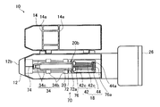
- FIG. 1 is a cross-sectional view showing an outline of an automatic injection apparatus according to the present invention
- FIG. 2 is a front view of the automatic injection apparatus 10 shown in FIG.
- FIG. 3 is a schematic cross-sectional view of the automatic injection device 10 with the syringe 70 removed.
- the syringe 70 attached to the automatic injection device 10 is disposed at the tip of the cylindrical syringe 72 and the syringe barrel 72 filled with a chemical solution, and is inserted into the body of the subject (patient).
- This is a normal syringe having a plunger 76 for discharging the liquid medicine from the injection needle 74.
- a flange 72 a that is locked to a locking groove 20 b of a syringe holding unit 20 described later is provided on the proximal end side of the syringe barrel 72.
- a flange 76a is provided on the proximal end side of the plunger 76 so as to be locked in a locking groove 44a of a pressing member 44 described later.
- the syringe 70 may be one in which the surgeon fills the chemical solution, or may be a prefilled syringe pre-filled with the chemical solution.
- the automatic injection device 10 is a device that mounts the syringe 70 in the housing 12 and automatically performs injection, and the housing 12, the cover 14, and a first drive unit for performing puncture with the injection needle 74 of the syringe 70.
- a second drive unit 18 for injecting a chemical solution by the syringe 70
- a syringe holding unit 20 for controlling the first drive unit 16 and the second drive unit 18, an operation unit 26,
- a battery 28 for supplying power to each unit.
- the syringe holding unit 20 is a part that holds the syringe 70 by making the longitudinal direction of the syringe 70 coincide with the driving direction of the first driving unit 16 described later.
- the syringe holding unit 20 includes a recess 20 a having a semicircular cross section perpendicular to the longitudinal direction corresponding to the shape of the syringe barrel 72 of the syringe 70 along the longitudinal direction of the syringe 70.
- a locking groove 20b for locking the flange 72a of the syringe barrel 72 is formed on the proximal end side (plunger 76 side) of the recess 20a.
- the syringe holding unit 20 is formed integrally with a block 34b and a base 36 of the first drive unit 16 described later.
- the first drive unit 16 moves the syringe holding unit 20 on which the syringe 70 is placed to the injection needle 74 side in the longitudinal direction of the syringe 70 to puncture the puncture needle 74 disposed at the distal end of the syringe 70. It is a part of. In the following description, a case where the syringe holding part 20 when the syringe 70 is placed is moved to the injection needle 74 side is a forward movement, and a case where the syringe holding part 20 is moved to the plunger 76 side is a backward movement.
- the first drive unit 16 includes a first motor 32, a first motion conversion unit 34, and a base 36.
- the first motor 32 is a normal stepping motor that operates according to supplied electric power, and can control the rotation speed and the rotation amount.
- the first motor 32 rotates a predetermined rotation amount at a predetermined rotation speed in a direction in which the syringe holding unit 20 moves forward (hereinafter referred to as a positive direction). After that, after stopping the operation for a predetermined time, a control described later is performed so that a predetermined rotation amount is rotated at a predetermined rotation speed in a direction in which the syringe holding unit 20 is retracted (hereinafter referred to as a reverse direction). Controlled by the unit 22.
- the first motor 32 is first input by the operation unit 26 and has a predetermined value corresponding to the preset operating conditions of the puncture speed and puncture depth. It is controlled by the control unit 22 so as to rotate the predetermined rotation amount in the positive direction at the rotation speed. After rotating a predetermined amount of rotation, the operation is temporarily stopped. Since the second drive unit 18 described later operates while the first motor 32 is once stopped, the stopped state is maintained until the operation of the second drive unit 18 is completed. After the operation of the second drive unit 18 is completed and a predetermined stop time has elapsed, a predetermined rotation amount is reversed in a reverse direction at a predetermined rotation speed according to a preset reverse speed (drawing speed) condition. It is controlled to rotate and return to its original position.
- the first motor 32 is connected to the screw shaft 34a of the first motion converter 34, and rotates the screw shaft 34a.
- the first motion conversion unit 34 is a so-called ball screw, and is a part for converting the rotational motion of the first motor 32 into a linear motion and moving the base 36 of the syringe holding unit 20 forward / backward.
- the first motion converter 34 includes a screw shaft 34a having a screw groove formed on the peripheral surface, two guide shafts 34c arranged symmetrically across the screw shaft 34a, a screw groove of the screw shaft 34a, and a plurality of screw grooves.
- An internal thread that is screwed through a ball is formed, and two blocks 34b are formed in which two guide holes are formed through which the two guide shafts 34c are inserted.
- the screw shaft 34a is rotatably supported by bearings formed on the housing 12 at both ends.
- Both ends of the guide shaft 34c are supported by the housing 12. Further, since the first motion conversion unit 34 is arranged such that the axis of the screw shaft 34a coincides with the longitudinal direction of the syringe 70 (injection needle 74), the injection needle 74 can be moved in the puncture direction. Further, the two blocks 34b are arranged in the longitudinal direction of the syringe 70 with a predetermined interval.
- a ball screw is used as the first motion converter 34.
- various known rotations such as a feed screw mechanism, a rack and pinion mechanism, and a crank mechanism can be used.
- a conversion mechanism between motion and linear motion may be used.
- a linear motor may be used instead of the first motor 32 and the first motion converter 34.
- the 1st motion conversion part 34 was set as the structure which has the two blocks 34b, it is not limited to this, It is good also as a structure which has the one block 34b. By disposing the two blocks 34b at a predetermined interval, the base 36 can be prevented from tilting and swinging in the front-rear direction.
- the base 36 is a base for mounting the syringe holding unit 20 and the second drive unit 18, and is fixed to the block 34 b of the first motion conversion unit 34. Since the base 36 is fixed to the block 34b of the first motion converter 34, when the first motor 32 is driven, the base 36 is moved forward / backward along the screw shaft 34a. That is, when the first motor 34 is driven, the syringe holding unit 20 and the second driving unit 18 are moved forward / backward integrally. As described above, in the illustrated example, the base 36 is formed integrally with the syringe holding unit 20 and the block 34b.
- the first motor 32 rotates a predetermined rotation amount at a predetermined rotation speed in accordance with conditions such as a puncture speed and a puncture depth set in advance by an input from the operation unit 26. As described above, it is controlled by the control unit 22. Therefore, first, when the first motor 32 rotates in the forward direction, the syringe holding unit 20 moves linearly to a predetermined position at a predetermined forward speed. Thereby, puncture is performed by the injection needle 74 of the syringe 70 to the set puncture depth at the set puncture speed. Next, while the first motor 32 is stopped, the base 36 maintains the stopped state. Thereafter, when the first motor rotates in the reverse direction, the base 36 moves linearly to the original position at a predetermined backward speed. Thereby, the injection needle 74 of the syringe 70 is extracted at a predetermined extraction speed.
- the puncture is performed automatically by pressing the syringe using the repulsive force of the spring. Therefore, the impact on the skin at the time of puncture (vibration, pressure, impact sound, etc.) There was a problem of giving fear and fear to the patient.
- the puncture and the injection are performed with the same spring, it is difficult to set detailed conditions for the puncture speed and the puncture depth according to the thickness of the injection needle, the type of medicine, the patient, and the like. It was.
- the first drive unit 16 that drives the syringe holding unit 20 is constituted by the first motor 32 and the first motion conversion unit 34 and has a syringe needle 74.
- 70 is held in the syringe holding unit 20, and the first driving unit 16 rotates according to the puncture speed and puncture depth set in advance, and the first motor 32 is rotated via the first motion conversion unit 34. Since the syringe holding unit 20 is advanced to puncture the injection needle 74, the puncture conditions such as the puncture speed can be set according to the thickness of the injection needle, the puncture depth, the patient, etc., and the puncture can be performed at an appropriate puncture speed.
- the advance speed when the first drive unit 16 advances the syringe holding unit 20 to perform puncture depends on the thickness of the injection needle 74, the puncture depth, the sensitivity of the patient, the injection site, or the like. Accordingly, it may be set appropriately.
- the puncture speed is preferably in the range of 10 mm / s to 500 mm / s, and preferably in the range of 25 mm / s to 500 mm / s. A range of 75 mm / s to 500 mm / s is preferable.
- the puncture speed By setting the puncture speed to 10 mm / s or more, the pain at the time of puncture can be reduced, and puncture can be performed with almost no pain, and when the puncture speed is set to 500 mm / s or less, Impact and recoil can be reduced, and patient anxiety and fear can be reduced.
- the range By setting the range from 25 mm / s to 500 mm / s, it is possible to perform almost painless puncture, and by setting the range from 75 mm / s to 500 mm / s, the pain during puncture can be reliably ensured. Painless puncture that does not feel.
- a preferable range of puncture speed will be described in detail later.
- the retracting speed when the first driving unit 16 retracts the syringe holding unit 20 and pulls out the injection needle 74 is not particularly limited, but is preferably in the range of 1 to 500 mm / s. . If the extraction speed is constant within the range of 1 to 500 mm / s, stimulation of the painful nerves caused by vibration of the needle already inserted and friction with the insertion site can be reduced, and the pain that occurs during extraction is minimized. It is preferable in that it can be made.
- the first drive unit 16 is configured so that a predetermined stop time elapses after the injection of the chemical liquid by the second drive unit 18 is completed based on the control of the control unit 22. Then, the syringe holding part 20 is retracted, and the injection needle 74 is pulled out. If the injection needle 74 is withdrawn immediately after the injection of the chemical solution, the chemical solution may not spread sufficiently and the chemical solution may leak. Therefore, after a predetermined stop time has elapsed from the completion of the injection of the chemical solution, Drawing is preferably performed. In the present embodiment, the operator can input and set the stop time until the injection needle 74 is pulled out from the operation unit 26.
- the first drive unit 16 not only automatically performs an operation for puncture in response to an input signal from the start button 26a, but can advance / retreat at a low speed according to the operation of the operation unit 26. it can. That is, the operator can move the first drive unit 16 forward / backward manually by operating the operation unit 26. Thereby, after setting the syringe 70 to the syringe holding
- the second drive unit 18 controls the control unit 22 to push the plunger 76 of the syringe 70 in the direction of the injection needle 74 and advance it to discharge the drug solution in the syringe barrel 72 from the tip of the injection needle 74. It is.
- the second drive unit 18 includes a second motor 40, a second motion conversion unit 42, and a pressing member 44.
- the second motor 40 is a normal stepping motor that operates according to the supplied electric power, and can control the rotation speed and the rotation amount.
- the second motor 40 temporarily stops the operation of the medicinal solution injection speed and injection amount set in advance by the input from the operation unit 26. It is controlled by the control unit 22 so as to rotate a predetermined rotation amount in the positive direction at a predetermined speed according to the conditions.
- the second motor 40 is connected to the screw shaft 42a of the second motion converter 42, and rotates the screw shaft 42a.
- the second motion conversion unit 42 is a ball screw, is a part that converts the rotational motion of the second motor 40 into a linear motion, and is a plunger 76 that is locked to the pressing member 44.
- the second motion conversion unit 42 includes a screw shaft 42a having a thread groove formed on the peripheral surface, and two guide shafts 42c arranged symmetrically across the screw shaft 42a. And a block 42b in which a female screw that is screwed into the screw groove of the screw shaft 42a via a plurality of balls is formed, and two guide holes are formed through which the two guide shafts 42c are respectively inserted.
- the screw shaft 42a is supported by a bearing formed on the base 36 so as to be rotatable at both ends. Both ends of the guide shaft 42c are supported by the base 36.
- the second motion conversion unit 42 is arranged with the axis of the screw shaft 42 a aligned with the longitudinal directions of the syringe 70 and the injection needle 74.
- the screw shaft 42a connected to the second motor 40 rotates.
- the block 42b screwed with the screw shaft 42a advances / retreats along the axis of the screw shaft 42a.
- the guide shaft 42c is inserted through the guide hole of the block 42b, when the screw shaft 42a rotates, the block 42b does not rotate around the screw shaft 42a, but linearly extends along the screw shaft 42a.
- a pressing member 44 is fixed to the block 42 b of the second motion conversion unit 42.
- the pressing member 44 is a member for pressing and moving the plunger 76 of the syringe 70, and is fixed to the block 42 b of the second motion conversion unit 42.
- the pressing member 44 is formed with a locking groove 44 a for locking the flange 76 a of the plunger 76. Since the pressing member 44 is fixed to the block 42b of the second motion converter 42, when the second motor 40 is driven, the pressing member 44 is moved forward / backward along the screw shaft 42a.
- the second motor 40 rotates a predetermined rotation amount at a predetermined rotation speed in accordance with conditions such as an injection speed and an injection amount set in advance by an input from the operation unit 26. In addition, it is controlled by the control unit 22. Therefore, when the second motor 40 rotates in the forward direction, the pressing member 44 is linearly moved to a predetermined position at a predetermined advance speed. Thereby, the plunger 76 of the syringe 70 is pressed, and a set amount of the drug solution is discharged from the tip of the injection needle 74 at a preset injection speed.
- the set puncture speed and puncture depth are provided by providing the second drive unit 18 for injecting the drug solution independently of the first drive unit 16 for performing the puncture. Regardless of this, since the injection rate and the injection amount can be set, the chemical solution can be injected at the optimum injection rate, and the discomfort associated with the injection of the chemical solution can be reduced. In addition, since the puncture speed by the first drive unit 16 can be set independently of the second drive unit 18, puncture can be performed at an optimum puncture speed, reducing puncture pain and at the time of puncture. Can reduce the impact.
- the injection speed when the second drive unit 18 advances the pressing member 44 and injects the chemical solution depends on the thickness and puncture depth of the injection needle 74 or the type and injection amount of the chemical solution. It can be set as appropriate. It is known that there is a correlation between the infusion rate of the drug solution and pain, and the slower the infusion rate, the less pain.
- the actual injection rate is optimal depending on the type of drug to be injected, the amount to be injected, the site to be injected, etc., but Nagasawa et al. Administer the rat oral mucosa by changing the injection rate of physiological saline.
- the injection rate is preferably in the range of 1 to 1000 ⁇ L / s.
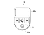
- FIG. 4 is a schematic view of the operation unit 26 of the automatic injection device 10 shown in FIG.
- the operation unit 26 is for an operator to perform an input operation.
- a start button 26a for starting the operation of the automatic injection device 10 and a display unit 26b for displaying input values and the like are provided.
- the configuration of the operation unit 26 is not limited to this, and may include a trackball or the like, or may be formed by a touch panel.
- the operation unit 26 supplies an input signal to the control unit 22 in response to an input operation.
- the control unit 22 controls each unit of the automatic injection device 10 based on an instruction input from the operation unit 26 by the operator.
- the control unit 22 controls the first drive unit 16 according to the puncture speed, puncture depth, stop time, and withdrawal speed that are set by inputting from the operation unit 26.
- the second drive unit is controlled according to the injection speed and the injection amount.
- the control unit 22 has a memory that stores operating conditions such as a set puncture speed, and controls each unit of the automatic injection device 10 according to the operating conditions stored in the memory. When a new operation condition is input from the operation unit 26, the operation condition stored in the memory is overwritten, and the automatic injection device 10 is controlled under the new operation condition. If there is no input, control is performed under the operating conditions already stored in the memory.
- the battery 28 supplies power to each part of the automatic injection device 10 such as the first motor 32, the second motor 40, the control unit 22, and the display unit 26b.
- the housing 12 includes a substantially cylindrical housing that accommodates and supports the first drive unit 16, the second drive unit 18, the syringe holding unit 20, the control unit 22, and the battery 28 therein. Is the body.
- Each of the first drive unit 16 and the second drive unit 18 is disposed in the housing 12 with the drive direction (the axial direction of the screw shafts (34 a, 42 a)) aligned with the longitudinal direction of the housing 12. Further, an insertion hole 12a through which the injection needle 74 is inserted when the syringe 70 is advanced is formed on one end surface of the housing 12.
- An operation unit 26 is disposed on the end surface of the housing 12 opposite to the contact surface 12b.
- the operation portion 26 is disposed so as to be inclined with respect to the contact portion 12 b of the housing 12.
- a part of the peripheral surface of the housing 12 is open, and a cover 14 is disposed in the open part so as to be openable and closable.
- the housing 12 and the cover 14 are connected by a hinge so as to be opened and closed.
- the cover 14 when the cover 14 is closed, the syringe barrel 72 of the syringe 70 is prevented from moving outside the longitudinal direction of the syringe 70, and the syringe 70 is detached from the syringe holding unit 20.
- a pressing portion 14a that prevents this is formed.
- 5A to 5C are schematic cross-sectional views for explaining the operation of the automatic injection device 10.
- the cover 12 is opened, and the syringe 70 filled with the drug solution in the syringe barrel 72 is set in the syringe holding unit 20 and the cover 12 is closed (FIG. 5A).
- the operation unit 26 is operated to adjust the position of the syringe holding unit 20 (the tip of the injection needle 74).
- a puncture speed, a puncture depth, an injection speed of a chemical solution, and the like are input and set from the operation unit 26 (stored in a memory). These operating conditions may be set in advance.
- the set puncture is performed under the control of the control unit 22.
- the first drive unit 16 operates according to the speed and the puncture depth, and the syringe holding unit 20 and the second drive unit 18 are advanced to a predetermined position (FIG. 5B).
- the injection needle 74 of the syringe 70 held by the syringe holding unit 20 protrudes from the insertion hole 12a and is punctured at the injection site of the patient.
- the 1st drive part 16 is comprised from the 1st motor 32 and the 1st motion conversion part 34, and is comprised so that an operation condition can be set
- maintenance part 20 is advanced at the set puncture speed.
- the needle can be punctured at an appropriate puncture speed according to the thickness of the injection needle, the puncture depth, the patient, etc., reducing pain during puncture and reducing impact during puncture. Can alleviate patient anxiety and fear.
- the first driving unit that performs puncturing is configured independently of the second driving unit 18 that injects the chemical solution, an appropriate puncturing speed (puncturing condition) regardless of the operating conditions of the second driving unit 18. Can be set.
- the first drive unit 16 After the puncturing operation by the first drive unit 16, the first drive unit 16 temporarily stops operating, and the control of the control unit 22 causes the second drive unit 18 to perform a predetermined amount at the set injection speed.
- the pressing member 44 is advanced so as to inject the chemical solution (FIG. 5C).
- the control unit 22 operates the first drive unit 16 after the predetermined stop time has elapsed, and moves the syringe holding unit 20 and the second drive unit 18 to the original ones. Withdrawn to position, the needle 74 is withdrawn from the patient.
- a display indicating the end of the operation may be displayed on the display unit 26b or the completion may be notified by voice.
- the automatic injection device 10 can automatically puncture the injection needle 74, inject the drug solution, and pull out the injection needle 74.
- the second drive unit 18 is placed on the base 36 of the first drive unit 16 and moved integrally with the syringe holding unit 20.
- the invention is not limited to this, and the second drive unit 18 may be fixed to the housing 12.
- the second drive unit 18 moves the syringe holding unit 20 forward when the syringe driving unit 20 is moved by the first drive unit 16.
- the pressing member 44 may be moved at the same speed as (or the reverse speed).
- the second drive unit 18 first advances the pressing member 44 at the same speed as the puncture speed simultaneously with the operation of the first drive unit 16 during the puncture operation by the first drive unit 16, and then While the operation of the first drive unit 16 is stopped, the pressing member 44 is advanced so as to inject the chemical at a predetermined injection speed, and after the predetermined stop time has elapsed, the pulling operation by the first drive unit 16 is performed. At the same time, simultaneously with the operation of the first drive unit 16, the pressing member 44 is retracted at the same speed as the drawing speed.
- the pressing member 44 only presses the flange 76a of the plunger 76 without forming the locking groove 44a in the pressing member 44. It is good also as a structure which does not stop.
- the second driving unit 18 moves the pressing member 44 to the position of the flange 76 a of the plunger 76. After that, the pressing member 44 is advanced so as to inject the chemical at a predetermined injection speed. Thereafter, after the second drive unit 18 retracts the pressing member 44 to the original position, the extraction operation by the first drive unit 16 is performed.
- the second drive unit 18 when the second drive unit 18 is fixed to the housing 12 and does not move, the mass of the moving object moved by the first drive unit 16 is reduced, and thus the reaction during puncture is reduced. Moreover, the output of the 1st motor 32 can be made small and it can reduce in weight using a small motor. On the other hand, when the second drive unit 18 is placed on the base 36 of the first drive unit 16 and moves integrally with the syringe holding unit 20, the control of the operation can be simplified.
- the chemical liquid is automatically injected by the second driving unit 18, but the present invention is not limited to this, and the second driving unit 18 does not have the second driving unit 18.
- Only one puncture operation by the one drive unit 16 may be automatically performed.
- only puncture may be performed automatically.
- the cover 14 has the pressing portion 14a, and the pressing portion 14a presses the syringe 70 to prevent the syringe 70 from being detached from the syringe holding portion 20.
- the syringe holding unit 20 may have a fixture for fixing the syringe 70.
- the first drive unit 16 retracts the syringe holding unit 20 and pulls out the injection needle 74.
- the time after the first driving unit 16 completes the puncture with the injection needle 74 by moving the syringe holding unit 20 forward is defined as a predetermined stop time. It is good also as a structure which retracts the syringe holding
- the first drive unit 16 is not limited to a configuration in which the extraction operation is performed after a predetermined stop time has elapsed, and the injection pressure related to the chemical injection by the second drive unit 18 is measured, and the injection pressure is set to a predetermined threshold value.
- the configuration may be such that the extraction operation by the first drive unit 16 is performed when the following occurs.
- a pressure sensor that measures the pressure applied from the plunger 76 is disposed on the pressing member 44, and the pressure applied to the pressure sensor is measured. Since it takes some time for the chemical solution injected into the body to spread in the body, the pressure applied from the chemical solution to the plunger 76 is high immediately after the injection of the chemical solution.
- the drug solution spreads in the body, and the pressure applied to the plunger 76 from the drug solution gradually decreases. Therefore, when the injection pressure measured by the pressure sensor is equal to or lower than a predetermined threshold value, by performing an extraction operation by the first drive unit 16, it is possible to prevent leakage of the chemical liquid when the injection needle 74 is extracted. Can do.
- a chemical solution is not injected into a subcutaneous tissue, muscle, or a predetermined site in a blood vessel but is accidentally injected into another tissue, a pressure abnormality occurs, and this can be detected to prevent erroneous administration. .
- the housing 12 is integrally formed with the distal end portion including the insertion hole 12a through which the injection needle 74 is inserted.
- the present invention is not limited to this, and the distal end portion including the insertion hole 12a is formed.
- the separate member may be configured to be replaceable.
- the distal end portion of the housing 12 is a portion that comes into contact with the patient's injection site, and since the injection needle 74 is inserted, there is a possibility that leaked chemical liquid or blood that has bleeds adheres, causing infection and the like. There is a fear. Therefore, by configuring the tip including the insertion hole 12a as a separate member from the housing 12, the tip contacting the patient's injection site can be kept clean and preventing infection and the like. Can do.
- the position adjustment of the tip position of the injection needle 74 when the syringe 70 is set in the automatic injection device 10 is performed manually by the operator by operating the operation unit 26.
- the present invention is not limited to this, and the tip position of the injection needle 74 may be automatically adjusted.
- the optical sensor is disposed at the distal end portion in the housing 12, the distal end position of the injection needle 74 is measured, and the first drive unit 16 is moved forward / backward according to the measurement result to adjust the position. Also good.
- the range of the position of the tip of the injection needle 74 (the distance from the contact surface 12b (insertion hole 12a) of the housing 12) in a state where the syringe 70 is set in the automatic injection device 10 is not particularly limited.
- the puncture set until the tip of the injection needle 74 reaches the patient's skin surface and puncture is started. It is preferable to have a sufficient distance to be accelerated to speed.
- the first drive unit 16 is configured to be controlled by the control unit 22 so as to perform puncture at a set constant puncture speed.
- the present invention is not limited to this, and the puncture is performed.
- the speed may be changed on the way.
- the puncture speed may be variably controlled so that puncture is performed at a high puncture speed until the skin dermis layer, and thereafter, the puncture is performed at a low puncture speed.
- a syringe 70 containing the same type of liquid medicine is basically used for one patient, first, the puncture speed, the puncture depth, the liquid medicine It is only necessary to set operating conditions such as the injection amount and stop time, and it is not necessary to set operating conditions for each injection.
- a detailed setting mode in which operation conditions such as a puncture speed, a puncture depth, a liquid injection amount, an injection speed, and a stop time can be set in detail, and a simple setting in which only the puncture speed can be set. It is good also as a structure which has a mode.
- the doctor sets the operating conditions in detail in the detailed setting mode, and in subsequent injections, only the puncture speed is reset in the simple setting mode according to the patient's preference. You may make it do.
- the setting of the puncture speed is not limited to numerical value input.
- the puncture speed may be selected from five puncture speeds set in advance by displaying “1” to “5”. It may be.
- the automatic injection device 10 is directly brought into contact with the puncture site at the contact surface 12b. However, the automatic injection device only needs to be able to specify the distance between the puncture needle 74 and the puncture site. A fixing aid for determining the relative position between the puncture site and the injection needle 74 may be disposed between 10 and the puncture site.
- the inventors of the present application show that the puncture resistance decreases depending on the puncture speed, and the pain reaction is suppressed in rat myoelectricity, and the puncture speed exceeds a certain puncture speed. Then, it was discovered that the pain response by puncture disappears. It is unclear how such an effect occurs in the pain sensory nerve of the skin, but Na ion channels and Ca that transmit excitement for stimulating the nerve ending, which is the skin pain sensory nerve, by high-speed puncture. It is considered that no action potential was generated in the ion channel or the like.
- the inventors of the present application have created a puncture device that can perform puncture similar to the automatic injection device 10 and measured the relationship between the puncture speed, puncture resistance, and myoelectricity using this puncture device. Then, a suitable range of puncture speed without pain response was determined.
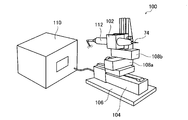
- FIG. 6 shows the puncture device 100.
- the puncture device 100 is an experimental device created to determine the relationship between the puncture speed and the myoelectric reaction, and can be equipped with various injection needles at the tip, and the puncture depth, puncture speed, withdrawal speed, etc. can be set The puncture is performed at the set puncture speed.
- the puncture device 100 basically has the same function as the device according to the present invention.
- the puncture device 100 includes a holding unit 102 that holds a load meter 112 with an injection needle 74 attached to the tip, a linear actuator 104 that advances the holding unit 102 to perform puncturing, and a holding unit 102 and a linear actuator 104.
- An X table 108 a and a Z table 108 b that are arranged to adjust the position of the holding unit 102, a controller 110 that controls the operation of the linear actuator 104, and a pedestal 106 on which the linear actuator 104 is placed.
- the linear actuator 104 includes a stepping motor and a ball screw.
- the puncture apparatus 100 performs puncture by causing the controller 110 to advance the linear actuator 104 at a set puncture speed.
- a puncture target rat a 7-8 week old SD male rat was purchased from Nippon Charles River Co., Ltd. and subjected to an experiment after an acclimatization period of 1 week.
- the body weight of the animals at the time of the experiment was 273 to 314 g.
- Rats were anesthetized by inhalation of isoflurane (Escaine from Mylan Pharmaceutical).
- the concentration with respect to air at the time of induction of anesthesia was 4% / Air, and the concentration at the time of recording measurement was 1.4 to 1.6% / Air.
- the body temperature was kept constant by heating to 42 ° C. with a heat insulating mat.
- puncture was performed using the puncture device 100, and the muscle action potential and puncture resistance were measured.
- 6 rats were punctured a total of 4 times with slightly different puncture positions on the soles of the feet. The needle was changed after every use.
- the puncture resistance was measured using a micro load meter (RX-1 / CPM-N manufactured by Aiko Engineering Co., Ltd.) as the load meter 112.
- the state of the puncture was observed at a speed of 4000 frames / second using a high speed microscope (VW-9000, manufactured by KEYENCE) and the state where the injection needle 74 was inserted into the skin of the rat sole. Marking the position 3 mm from the tip of the injection needle 74 so that the embedding position in the skin can be discriminated, and measuring the moving distance of the needle per unit time from the image of the high-speed microscope, the actual puncture speed was calculated.
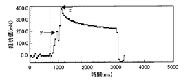
- FIG. 7 shows a graph of puncture resistance measured when a 27G needle was punctured at a puncture speed of 15 mm / s.
- the horizontal axis is time [ms]
- the vertical axis is resistance value (piercing resistance) [mN].
- the time when the tip of the injection needle 74 was in contact with the skin was read from the image of the high speed microscope and indicated by a dotted line in FIG.
- the time when the jaw part of the needle blade surface of the injection needle 74 reaches the skin surface is read and is indicated by an arrow y in FIG. 7, and the time when the puncture of the injection needle 74 is completed (when the puncture depth is 3 mm).
- FIG. 8A shows the resistance value when the puncture of the injection needle 74 is completed (puncture depth 3 mm) (arrow z).
- the recording of the muscle action potential is a high sensitivity bioelectric amplifier (CYGNUS TECHNOLOGY) with a needle-shaped bipolar electrode as a recording electrode, and after removing the chest skin, aluminum foil is attached as a ground electrode.
- CYGNUS TECHNOLOGY high sensitivity bioelectric amplifier
- the low-pass filter and high-pass filter of the high-sensitivity bioelectric amplifier were set to 3 kHz and 300 Hz, respectively.
- the rat was held with the paw extended as much as possible.
- a clip-type stimulation electrode (Unique Medical TH207-123) is used, the back and back of the rat hind limb is sandwiched, and the electrical stimulation device (DASIN BSI- Pain electrical stimulation (pulse condition: 40 Hz, 2 ms, 5 mA) was applied by a 950 Biphasic Stimulus Isolator. An incision was made by drawing a line of about 1 cm on the part where the muscle contracted.
- the muscle was exposed, and the painful electrical stimulation was applied again, and the recording electrode needle was securely placed in the contracted portion of the muscle. Thereafter, pain electrical stimulation was performed again, and the anesthetic depth of the rat was finely adjusted from the reaction intensity of the action potential (maximum amplitude value) of myoelectricity.
- the reaction of muscle activity induced by electrical stimulation and pressure stimulation was recorded on a recording device (PowerLab manufactured by ADInstruments) at a sampling interval of 0.1 ms.
- the recorded data was subjected to a 30-Hz high-pass digital filter processing with a recording device to remove the influence of body movement caused by electrical stimulation and pressure stimulation.
- FIG. 8A an average value of measured resistance values and a standard error are shown.
- FIG. 8B shows the average value of the measured total power and the standard error.
- the myoelectric reaction amount was measured using a rat, but it is considered that the same tendency as that of a rat is basically exhibited in the case of a human body.
- Example 2 Except for changing the puncture speed to 15 mm / s, the puncture resistance and the amount of myoelectric reaction were determined in the same manner as in Example 1.
- the resistance value at the time (arrow z) when the puncture of the injection needle 74 is completed (puncture depth 3 mm) is shown in FIG. 8 (A), and the myoelectric reaction amount (Total Power) is shown in FIG. 8 (B).
- Example 3 Penetration resistance and myoelectric reaction amount were determined in the same manner as in Example 1 except that the puncture speed was changed to 75 mm / s.
- the resistance value at the time (arrow z) when the puncture of the injection needle 74 is completed (puncture depth 3 mm) is shown in FIG. 8 (A), and the myoelectric reaction amount (Total Power) is shown in FIG. 8 (B).
- Example 4 The penetration resistance and myoelectric reaction amount were determined in the same manner as in Example 1 except that the thickness of the injection needle 74 was changed to 31G (Microfine Plus ⁇ 0.25 ⁇ 5 mm manufactured by Becton Dickinson). The resistance value at the time (arrow z) when the puncture of the injection needle 74 is completed (puncture depth 3 mm) is shown in FIG. 9 (A), and the myoelectric reaction amount (Total Power) is shown in FIG. 9 (B).
- Example 5 Penetration resistance and myoelectric reaction amount were determined in the same manner as in Example 4 except that the puncture speed was changed to 15 mm / s.
- the resistance value at the time (arrow z) when the puncture of the injection needle 74 is completed (puncture depth 3 mm) is shown in FIG. 9 (A), and the myoelectric reaction amount (Total Power) is shown in FIG. 9 (B).
- Example 6 The puncture resistance and myoelectric reaction amount were determined in the same manner as in Example 4 except that the puncture speed was changed to 75 mm / s.
- the resistance value at the time (arrow z) when the puncture of the injection needle 74 is completed (puncture depth 3 mm) is shown in FIG. 9 (A), and the myoelectric reaction amount (Total Power) is shown in FIG. 9 (B).
- the puncture resistance increases in resistance as the injection needle 74 is embedded in the skin, and shows a first peak (arrow y) where the jaw portion of the needle blade surface has reached. Recognize. Thereafter, the resistance value once decreases, rises again as the cannula portion of the needle enters, and shows the maximum value when the puncture is stopped (puncture depth 3 mm, arrow z). After that, while the movement of the injection needle 74 is stopped (for 2 seconds), the resistance value changes at a constant value. When the extraction of the injection needle 74 is started, the resistance value decreases rapidly. You can see that
- the resistance value at the time of puncture is higher for the 31G injection needle than for 27G, that is, the thinner the needle is. It turns out that it becomes small. Further, it can be seen that in both the 27G and 31G injection needles, the resistance value at the time of puncture decreases as the puncture speed increases in proportion to the puncture speed. 8 shows the resistance value and myoelectric reaction amount of 27G, and FIG. 9 shows the resistance value and myoelectric reaction amount of 31G.
- the thickness 31G of the injection needle 74 is half the amount of myoelectric reaction compared to 27G. It turns out that it is the following. Further, it can be seen that in both cases of the thicknesses 31G and 27G of the injection needle 74, when the puncture speed is 15 mm / s, the myoelectric reaction amount is greatly reduced as compared with the puncture speed of 3 mm / s. Further, when the puncture speed was 75 mm / s, no myoelectric reaction appeared regardless of the thickness of the injection needle 74. The measured values are shown as an average value and standard error when 6 rats were punctured 4 times, respectively, and a statistical significance test was performed using a one-way analysis of variance (**: p ⁇ 0.01). ).
- the puncture speed is set to 10 mm / s or more, so that the amount of myoelectric reaction is greatly reduced and the puncture can be performed with almost no pain. You can see that it can be done. It can also be seen that by setting the puncture speed to 25 m / s or more, the myoelectric reaction can be made almost zero and the puncture can be performed almost painlessly. Furthermore, it can be seen that, by setting the puncture speed to 75 m / s or more, it is possible to perform puncture without pain without causing a myoelectric reaction.
Abstract
Description
皮下、静脈内、筋肉内投与など注射針による投与は、現在、一般的な投与方法であるが、注射針を刺して薬液を注入するため針が皮膚を貫く際の痛みを伴う。そのため、注射器を使用して薬液を投与される患者に、注射針を刺した時の痛みや薬液の注入時の不快感に対して恐怖心が生じて、薬物治療を拒否したり否定的になってしまうことがあり、このことが治療の遅れに繋がっている。特に、インスリン注射が必要な糖尿病患者や、成長ホルモン注射が必要な成長不全患者には、小児が多く、注射時の痛みや不快感がその後の「注射恐怖症」(Needle phobia)を生む原因ともなっている。
そこで、このような小児の患者を含めて、注射時の操作が簡便で痛みを伴わず、また、注射針やシリンジに直接触れることなく自動的に注射ができる装置が望まれている。 Currently, the use of protein preparations such as molecular targeted drugs, vaccines, and hormones such as insulin, etc., has rapidly increased as drugs, and devices that can easily administer these drugs are required. Since these drugs are high molecular weight proteins or peptides and are not absorbed into the body by oral administration, they must be administered subcutaneously or intravascularly with an injection needle.
Administration by an injection needle such as subcutaneous, intravenous, or intramuscular administration is currently a common administration method, but it is accompanied by pain when the needle penetrates the skin because a medical solution is injected through the injection needle. For this reason, patients who are given medicinal solutions using syringes are terrified of the pain of sticking needles and the discomfort of injecting medicinal solutions, refusing or negative drug treatment. This can lead to delays in treatment. In particular, there are many children in diabetic patients who need insulin injections and growth failure patients who need growth hormone injections, and pain and discomfort at the time of injection may cause subsequent “needle phobia”. ing.
Therefore, there is a demand for a device including such a pediatric patient that can be easily injected at the time of injection without causing pain and automatically injecting without directly touching the injection needle or syringe.
例えば、特許文献1には、駆動アセンブリと同駆動アセンブリに取り付けられた注射器アセンブリとを含み、駆動アセンブリが、駆動ロッドと、駆動ロッドに解除自在に結合された駆動装置と、駆動ロッドを注射器アセンブリに向けて付勢する一定力のばねとを含む装置が記載されている。この装置は、ばねが装置の軸線に沿って結合された駆動ロッドと駆動装置とを付勢して、注射器アセンブリの針によって皮膚を穿刺し、次いで、駆動ロッドが駆動装置から外され、ばねが駆動ロッドを軸線方向に付勢し続けることによって、駆動ロッドが注射器アセンブリ内のピストンと係合して内部の薬剤を押し出すことによって、自動的に注射を行う。 On the other hand, as an automatic injection device capable of easily administering a drug solution by an individual patient, a syringe (syringe) and a pusher (plunger) of the syringe are pressed by a spring force to automatically perform puncture and injection. A device has been proposed.
For example, Patent Document 1 includes a drive assembly and a syringe assembly attached to the drive assembly. The drive assembly includes a drive rod, a drive device releasably coupled to the drive rod, and the drive rod. And a constant force spring biasing toward the. This device urges a drive rod and drive device, with springs coupled along the axis of the device, to puncture the skin with the needle of the syringe assembly, then the drive rod is removed from the drive device and the spring is By continuing to urge the drive rod in the axial direction, the drive rod engages with the piston in the syringe assembly to push out the medicament inside and automatically make an injection.
また、穿刺時の痛みを軽減するために、径を細くした注射針が開発され、臨床で使われてきたが、大量の投与や、粘度の高い薬剤の投与には、注入抵抗が大きくなり、長時間を要する。 In the dental field, an electric injector that automatically injects a chemical solution at a constant speed is used as a device for administering an anesthetic. However, the needle is punctured by an operator, and the puncture is performed. Is not automatic.
In order to reduce pain at the time of puncture, an injection needle with a reduced diameter has been developed and used clinically. However, injection resistance increases for large doses and high-viscosity drugs. It takes a long time.
また、本発明の別の目的は、穿刺の痛みが非常に少なく、ほぼ無痛の穿刺速度で自動的に穿刺を行うことができる自動注射装置を提供することにある。 The object of the present invention is to eliminate the above-mentioned problems of the prior art and perform puncture automatically, and can set puncture conditions according to the thickness of the injection needle, the puncture depth, etc. An object of the present invention is to provide an automatic injection device that can reduce pain at the time of injection, reduce impact at the time of puncture, and reduce anxiety and fear of a patient.
Another object of the present invention is to provide an automatic injection apparatus that can perform puncture automatically at a puncture speed that is very painless with very little puncture pain.
また、シリンジの注射針の太さは、18G~34Gの範囲にあり、第1駆動部による注射針の穿刺の際の穿刺速度は、10~500mm/sを満たすのが好ましい。 Here, it is preferable that the first drive unit includes a first electric motor and a first motion conversion unit that converts the rotational motion of the first electric motor into a linear motion and advances the syringe holding unit.
The thickness of the injection needle of the syringe is in the range of 18G to 34G, and the puncture speed when the first drive unit punctures the injection needle preferably satisfies 10 to 500 mm / s.
また、第1駆動部は、第2駆動部をシリンジ保持部と一体的に移動させるのが好ましい。
また、制御部は、第2駆動部による薬液の注入速度を、1~1000μL/sに制御するのが好ましい。 Furthermore, it is preferable that a 2nd drive part is provided with the 2nd motion conversion part which converts the rotational motion of a 2nd electric motor and a 2nd electric motor into a linear motion.
Moreover, it is preferable that a 1st drive part moves a 2nd drive part integrally with a syringe holding part.
Further, it is preferable that the control unit controls the injection rate of the chemical solution by the second driving unit to 1 to 1000 μL / s.
また、制御部は、第2駆動部による薬液注入の後、所定の停止時間が経過した後に、シリンジ保持部を後退させて、注射針を引き抜くように、第1駆動部を制御するのが好ましい。
また、制御部は、第1駆動部による注射針の穿刺において、穿刺途中の速度を可変に制御するのが好ましい。 Further, the control unit controls the first drive unit so that the puncture depth when the first drive unit advances the syringe holding unit to puncture the injection needle is 1 to 50 mm. preferable.
Moreover, it is preferable that the control unit controls the first driving unit so that the syringe holding unit is retracted and the injection needle is pulled out after a predetermined stop time has elapsed after the liquid injection by the second driving unit. .
In addition, it is preferable that the control unit variably controls the speed during the puncture in the puncture of the injection needle by the first drive unit.
また、本発明の好ましい態様によれば、注射針の太さが、18G~34Gの範囲の場合に、第1駆動部による穿刺の際の穿刺速度が、10~500mm/sを満たすことで、穿刺の痛みが非常に少なく、ほぼ無痛の穿刺速度で自動的に穿刺を行うことができる。 According to the present invention, when performing puncture automatically, puncture conditions can be set according to the thickness of the injection needle, the puncture depth, etc., reducing pain during puncture and reducing impact during puncture. And alleviate the patient's anxiety and fear.
According to a preferred aspect of the present invention, when the thickness of the injection needle is in the range of 18G to 34G, the puncture speed at the time of puncture by the first drive unit satisfies 10 to 500 mm / s, Puncture pain is very small, and puncture can be performed automatically at a nearly painless puncture speed.
図1は、本発明に係る自動注射装置の概略を示す断面図であり、図2は、図1に示した自動注射装置10のカバー14を開いた状態の正面図である。
また、図3は、シリンジ70を外した状態の自動注射装置10の概略断面図である。 The automatic injection device according to the present invention will be described in detail below based on a preferred embodiment shown in the accompanying drawings.
FIG. 1 is a cross-sectional view showing an outline of an automatic injection apparatus according to the present invention, and FIG. 2 is a front view of the
FIG. 3 is a schematic cross-sectional view of the
図示例においては、注射筒72の基端側には、後述するシリンジ保持部20の係止溝20bに係止されるフランジ72aが設けられている。
また、プランジャ76の基端側には、後述する押圧部材44の係止溝44aに係止されるフランジ76aが設けられている。 The
In the illustrated example, a
A
図2および図3に示すように、シリンジ保持部20は、シリンジ70の長手方向に沿って、シリンジ70の注射筒72の形状に対応した、長手方向に垂直な断面が半円形の凹部20aを有している。また、凹部20aの基端側(プランジャ76側)には、注射筒72のフランジ72aが係止されるための係止溝20bが形成されている。 The
As shown in FIG. 2 and FIG. 3, the
なお、以下の説明においては、シリンジ70を載置したときのシリンジ保持部20を注射針74側に移動させる場合を前進とし、シリンジ保持部20をプランジャ76側に移動させる場合を後退とする。
第1駆動部16は、第1モータ32と、第1運動変換部34と、ベース36とを有する。 The
In the following description, a case where the
The
第1モータ32は、シリンジ保持部20を前進させる方向(以下、正方向とする)に、所定の回転速度で所定の回転量を回転する。その後、所定の時間の間、動作を停止した後に、シリンジ保持部20を後退させる方向(以下、逆方向とする)に、所定の回転速度で所定の回転量を回転するように、後述する制御部22によって制御される。 The
The
第1モータ32は、第1運動変換部34のねじ軸34aと接続されており、ねじ軸34aを回転させる。 Specifically, when the
The
第1運動変換部34は、周面にねじ溝が形成されたねじ軸34aと、ねじ軸34aを挟んで対称に配置される2本の案内軸34cと、ねじ軸34aのねじ溝と複数のボール(玉)を介して螺合する雌ねじが形成され、かつ、2本の案内軸34cがそれぞれ挿通される2つの案内孔が形成された2つのブロック34bとを有する。
ねじ軸34aは、両端部側で、ハウジング12に形成された軸受に回転可能に支持されている。また、案内軸34cは、両端部がハウジング12に支持されている。
また、第1運動変換部34は、ねじ軸34aの軸を、シリンジ70(注射針74)の長手方向と一致させて配置されているので、注射針74を穿刺方向に移動させることができる。
また、2つのブロック34bは、シリンジ70の長手方向に、所定の間隔を持って配置される。 The first
The
The
Further, since the first
Further, the two
第1運動変換部34の2つのブロック34bには、ベース36が固定されている。 When the
A
あるいは、第1モータ32および第1運動変換部34に変えて、リニアモータを用いてもよい。
なお、位置精度が高く制御性が良い点や摩擦損失が少なくエネルギ効率が高い点で、第1運動変換部34として、ボールねじを用いることが好ましい。
また、第1運動変換部34は、2つのブロック34bを有する構成としたが、これに限定はされず、1つのブロック34bを有する構成としてもよい。2つのブロック34bを所定の間隔で配置することにより、ベース36が前後方向に傾いて揺動することを防止できる。 In the illustrated example, a ball screw is used as the
Alternatively, a linear motor may be used instead of the
In addition, it is preferable to use a ball screw as the first
Moreover, although the 1st
ベース36は、第1運動変換部34のブロック34bに固定されているので、第1モータ32が駆動すると、ねじ軸34aに沿って前進/後退される。すなわち、第1モータ34が駆動すると、シリンジ保持部20および第2駆動部18が、一体的に前進/後退される。
なお、前述のとおり、図示例においては、ベース36は、シリンジ保持部20およびブロック34bと一体に形成されている。 The
Since the
As described above, in the illustrated example, the
次に、第1モータ32が停止している間、ベース36は停止した状態を維持する。その後、第1モータが逆方向に回転することにより、ベース36は、所定の後退速度で、元の位置まで直線的に移動する。これにより、シリンジ70の注射針74は、所定の引抜速度で引き抜かれる。 Here, as described above, the
Next, while the
また、穿刺を行う第1駆動部が、薬液の注入を行う第2駆動部18とは独立に構成されるので、第2駆動部18の動作条件に係らず、適切な穿刺速度を設定することができる。 On the other hand, in the
In addition, since the first driving unit that performs puncturing is configured independently of the
また、25mm/s~500mm/sの範囲とすることにより、ほぼ無痛の穿刺を行うことができ、さらに、75mm/s~500mm/sの範囲とすることにより、確実に穿刺の際の痛みを感じさせない無痛の穿刺を行うことができる。
好ましい穿刺速度の範囲については後に詳述する。 By setting the puncture speed to 10 mm / s or more, the pain at the time of puncture can be reduced, and puncture can be performed with almost no pain, and when the puncture speed is set to 500 mm / s or less, Impact and recoil can be reduced, and patient anxiety and fear can be reduced.
In addition, by setting the range from 25 mm / s to 500 mm / s, it is possible to perform almost painless puncture, and by setting the range from 75 mm / s to 500 mm / s, the pain during puncture can be reliably ensured. Painless puncture that does not feel.
A preferable range of puncture speed will be described in detail later.
引抜速度を1~500mm/sの範囲内で一定速度とすると、既に刺入されている針の振動や刺入部位との摩擦による痛覚神経への刺激を軽減でき、引き抜き時に生じる痛みを最小限にできる点で好ましい。 Further, the retracting speed when the
If the extraction speed is constant within the range of 1 to 500 mm / s, stimulation of the painful nerves caused by vibration of the needle already inserted and friction with the insertion site can be reduced, and the pain that occurs during extraction is minimized. It is preferable in that it can be made.
本実施例においては、注射針74を引き抜くまでの停止時間についても、操作者が操作部26から入力して設定することができる。 Moreover, in this embodiment, as a preferable aspect, the
In the present embodiment, the operator can input and set the stop time until the
第2駆動部18は、第2モータ40と、第2運動変換部42と、押圧部材44とを有する。 The
The
第2モータ40は、第1駆動部16が穿刺の動作を行った後、一旦、動作を停止している間に、操作部26からの入力によって予め設定された薬液の注入速度および注入量の条件に応じた所定の速度で、所定の回転量を正方向に回転するように、制御部22によって制御される。
第2モータ40は、第2運動変換部42のねじ軸42aと接続されており、ねじ軸42aを回転させる。 Similar to the
After the
The
第2運動変換部42は、第1運動変換部34と同様に、周面にねじ溝が形成されたねじ軸42aと、ねじ軸42aを挟んで対称に配置される2本の案内軸42cと、ねじ軸42aのねじ溝に複数のボールを介して螺合する雌ねじが形成され、かつ、2本の案内軸42cがそれぞれ挿通される2つの案内孔が形成されたブロック42bとを有する。
ねじ軸42aは、ベース36に形成された軸受に両端部側で回転可能に支持されている。また、案内軸42cは、両端部がベース36に支持されている。
また、第2運動変換部42は、ねじ軸42aの軸を、シリンジ70および注射針74の長手方向と一致させて配置される。 Similar to the first
Similarly to the first
The
The second
第2運動変換部42のブロック42bには、押圧部材44が固定されている。 When the
A pressing
押圧部材44には、プランジャ76のフランジ76aを係止するための係止溝44aが形成されている。
押圧部材44は、第2運動変換部42のブロック42bに固定されているので、第2モータ40が駆動すると、ねじ軸42aに沿って、前進/後退される。 The pressing
The pressing
Since the pressing
薬液の注入速度を1~1000μL/sの範囲とすることにより、薬液の注入に伴う痛みや不快感を低減することができる。 Here, the injection speed when the
By setting the injection rate of the chemical solution in the range of 1 to 1000 μL / s, pain and discomfort associated with the injection of the chemical solution can be reduced.
操作部26は、操作者が入力操作を行うためのものである。図示例においては、動作条件を入力するための十字キー、決定ボタン等に加えて、自動注射装置10の動作を開始させるためのスタートボタン26a、および、入力値等を表示する表示部26bを有する。
なお、操作部26の構成はこれに限定はされず、トラックボール等を有してもよく、あるいはタッチパネルにより形成されてもよい。
操作部26は、入力操作に応じで、入力信号を制御部22に供給する。 FIG. 4 is a schematic view of the
The
The configuration of the
The
例えば、穿刺速度のみが入力される構成とし、穿刺深さ、薬液の注入速度、薬液の注入量、および、薬液注入後の停止時間は予め設定されていてもよい。
また、穿刺速度を直接入力する構成にも限定はされず、注射針74の太さ、薬液の種類、穿刺深さ、薬液の注入量、穿刺部位の少なくとも1つが操作部26から入力され、入力された値に応じて、制御部22が最適な穿刺速度を自動的に選択する構成としてもよい。 In the illustrated example, as operating conditions, a puncture speed, a puncture depth, a size of an attached syringe, a liquid injection speed, a liquid injection amount, and a stop time after liquid injection are input from the
For example, only the puncture speed may be input, and the puncture depth, the injection rate of the chemical solution, the injection amount of the chemical solution, and the stop time after the injection of the chemical solution may be set in advance.
Further, the configuration for directly inputting the puncture speed is not limited, and at least one of the thickness of the
本実施例においては、制御部22は、操作部26から入力され設定された穿刺速度、穿刺深さ、停止時間、引抜速度に応じて、第1駆動部16を制御し、また、設定された注入速度、注入量に応じて、第2駆動部を制御する。
また、制御部22は、設定された穿刺速度等の動作条件を記憶するメモリを有し、メモリに記憶された動作条件に応じて、自動注射装置10の各部の制御を行う。また、操作部26から新たな動作条件が入力された場合には、メモリに記憶された動作条件を上書きし、新たな動作条件で、自動注射装置10の制御を行う。また、入力がない場合には、すでにメモリに記憶されている動作条件で制御を行う。 The
In the present embodiment, the
In addition, the
第1駆動部16および第2駆動部18はそれぞれ、駆動方向(ねじ軸(34a、42a)の軸方向)をハウジング12の長手方向に一致させて、ハウジング12内に配置される。また、ハウジング12の一方の端面には、シリンジ70が前進された際に注射針74が挿通する挿通孔12aが形成されている。さらに、ハウジング12の挿通孔12aが形成されている部分はその外面で皮膚などの穿刺対象部位と当接する当接面12bとなっている。自動注射装置10で薬液を投与する際には、動作条件を確認した後、当接面12bを皮膚などの穿刺対象部位に当接させ、投与操作を開始するので、注射針74の先端が挿通孔12aから突出した長さが、そのまま穿刺深さとなる。 As shown in FIGS. 2 and 3, the
Each of the
なお、図示例においては、操作部26は、ハウジング12の当接部12bに対して傾斜されて配置されている。操作部26を傾斜させて配置することにより、患者が自動注射装置10を操作する際に、操作部26の表示部26bを視認しやすくなる。 An
In the illustrated example, the
また、カバー14の内側面には、カバー14を閉じた際に、シリンジ70の注射筒72を、シリンジ70の長手方向以外に移動することを抑制し、シリンジ70がシリンジ保持部20から離脱することを防止する押さえ部14aが形成されている。 Further, a part of the peripheral surface of the
Further, on the inner side surface of the
図5(A)~(C)は、自動注射装置10の動作を説明するための概略断面図である。
まず、カバー12が開放され、注射筒72内に薬液が充填されたシリンジ70が、シリンジ保持部20にセットされて、カバー12が閉じられる(図5(A))。このとき、必要であれば、操作部26を操作して、シリンジ保持部20(注射針74先端)の位置調整を行う。
次に、操作部26から穿刺速度、穿刺深さ、薬液の注入速度等が入力され設定される(メモリに記憶される)。なお、これらの動作条件は事前に設定されていてもよい。 Next, the operation of the
5A to 5C are schematic cross-sectional views for explaining the operation of the
First, the
Next, a puncture speed, a puncture depth, an injection speed of a chemical solution, and the like are input and set from the operation unit 26 (stored in a memory). These operating conditions may be set in advance.
ここで、第1駆動部16は、第1モータ32と第1運動変換部34とから構成され、動作条件を設定可能に構成されるので、設定された穿刺速度でシリンジ保持部20を前進させて穿刺を行うことができ、注射針の太さや穿刺深さ、患者等に応じて、適切な穿刺速度で穿刺することができ、穿刺時の痛みを低減すると共に、穿刺時の衝撃を低減し、患者の不安や恐怖を軽減することができる。
また、穿刺を行う第1駆動部が、薬液の注入を行う第2駆動部18とは独立に構成されるので、第2駆動部18の動作条件に係らず、適切な穿刺速度(穿刺条件)を設定することができる。 When the
Here, since the
In addition, since the first driving unit that performs puncturing is configured independently of the
第2駆動部18による薬液の注入動作が終了すると、制御部22は、所定の停止時間が経過の後に、第1駆動部16を動作させ、シリンジ保持部20および第2駆動部18を元の位置まで後退させて、注射針74を患者から引き抜く。
なお、第1駆動部16の引抜動作が終了した後に、動作終了を示す表示を表示部26bに表示したり、音声で完了を知らせるようにしてもよい。
以上のように、本発明に係る自動注射装置10は、注射針74の穿刺、薬液の注入および注射針74の引き抜きを自動で行うことができる。 After the puncturing operation by the
When the injection operation of the chemical solution by the
In addition, after the pulling-out operation of the
As described above, the
第2駆動部18をハウジング12に固定する構成とした場合には、例えば、第2駆動部18は、第1駆動部16によるシリンジ保持部20の移動の際に、シリンジ保持部20の前進速度(あるいは後退速度)と同じ速度で押圧部材44を移動させればよい。
すなわち、第2駆動部18は、まず、第1駆動部16による穿刺動作の際に、第1駆動部16の動作と同時に、穿刺速度と同じ速度で押圧部材44を前進させ、次に、第1駆動部16の動作が停止している間に、所定の注入速度で薬液を注入するように押圧部材44を前進させ、所定の停止時間が経過した後に、第1駆動部16による引抜動作の際に、第1駆動部16の動作と同時に、引抜速度と同じ速度で押圧部材44を後退させる。 Here, in the
When the
That is, the
この場合は、第1駆動部16によってシリンジ70が載置されたシリンジ保持部が移動し穿刺がされた後に、第2駆動部18が、押圧部材44をプランジャ76のフランジ76aの位置まで移動させた後に、所定の注入速度で薬液を注入するように押圧部材44を前進させる。その後、第2駆動部18が押圧部材44を元の位置まで後退させてから、第1駆動部16のよる引抜動作が行われる。 Alternatively, as another example of the configuration in which the
In this case, after the syringe holding unit on which the
一方、第2駆動部18を、第1駆動部16のベース36上に載置し、シリンジ保持部20と一体的に移動する構成とすると、動作の制御を単純にすることができる。 As described above, when the
On the other hand, when the
具体的には、押圧部材44に、プランジャ76からかかる圧力を測定する圧力センサを配置して、圧力センサにかかる圧力を測定する。体内に注入された薬液が、体内に広がるまでには、ある程度時間がかかるため、薬液の注入直後は、薬液からプランジャ76にかかる圧力は高くなっている。時間が経つにつれ、薬液が体内に広がり、薬液からプランジャ76にかかる圧力が徐々に低くなっていく。したがって、圧力センサで測定した注入圧力が、所定の閾値以下となった場合に、第1駆動部16による引き抜き動作を行うことにより、注射針74を引き抜いた際の、薬液の漏れを防止することができる。また、薬液が皮下組織や筋肉、血管内の所定の部位に注入されず、誤って別組織に注入された場合は、圧異常が生じるため、これを感知し未然に誤投与を防ぐことができる。 The
Specifically, a pressure sensor that measures the pressure applied from the
ハウジング12の先端部は、患者の注射部位と接触する部位であり、また、注射針74が挿通するため、漏れた薬液や、出血した血が付着する可能性があり、感染等が問題となるおそれがある。そのため、挿通孔12aを含む先端部を、ハウジング12とは別部材として、交換可能に構成することにより、患者の注射部位と接触する先端部を清潔に保つことができ、感染等を予防することができる。 In the illustrated example, the
The distal end portion of the
なお、シリンジ70を自動注射装置10にセットした状態の注射針74の先端の位置(ハウジング12の当接面12b(挿通孔12a)からの距離)の範囲については特に限定はないが、第1駆動部16の性能や、シリンジ保持部20と第2駆動部18の質量等に応じて、注射針74の先端が患者の皮膚表面に到達し、穿刺が開始されるまでに、設定された穿刺速度まで加速されるために十分な距離を有するのが好ましい。 In the above embodiment, the position adjustment of the tip position of the
The range of the position of the tip of the injection needle 74 (the distance from the
また、操作部26から入力を行うに際し、穿刺速度、穿刺深さ、薬液の注入量、注入速度、停止時間等の動作条件を詳細に設定できる詳細設定モードと、穿刺速度のみを設定できる簡易設定モードとを有する構成としてもよい。自動注射装置を初めて使用する際に、医師が詳細設定モードで動作条件を詳細に設定し、以降の注射の際には、簡易設定モードで、患者の好みに応じて、穿刺速度のみを再設定するようにしてもよい。また、簡易設定モードでは、穿刺速度の設定は、数値入力に限定はされず、例えば、「1」~「5」などの表示によって5段階に予め設定された穿刺速度から選択して設定するようにしてもよい。
また、上記実施例においては、自動注射装置10を当接面12bで直接、穿刺部位に当接させるものとしたが、穿刺針74と穿刺部位との間の距離が特定できればよく、自動注射装置10と穿刺部位との間に、穿刺部位と注射針74との相対的な位置を定める固定補助具を配置してもよい。 In addition, when such an automatic injection device is used, since a
In addition, when performing an input from the
In the above embodiment, the
そこで、本願発明者らは、自動注射装置10と同様の穿刺を行うことができる穿刺装置を作成して、この穿刺装置を用いて、穿刺速度と、刺通抵抗および筋電との関係を測定し、疼痛反応がない好適な穿刺速度の範囲を求めた。 When performing puncture with an injection needle, the inventors of the present application show that the puncture resistance decreases depending on the puncture speed, and the pain reaction is suppressed in rat myoelectricity, and the puncture speed exceeds a certain puncture speed. Then, it was discovered that the pain response by puncture disappears. It is unclear how such an effect occurs in the pain sensory nerve of the skin, but Na ion channels and Ca that transmit excitement for stimulating the nerve ending, which is the skin pain sensory nerve, by high-speed puncture. It is considered that no action potential was generated in the ion channel or the like.
Therefore, the inventors of the present application have created a puncture device that can perform puncture similar to the
穿刺装置100は、穿刺速度と筋電反応との関係を求めるために作製した実験用の装置であり、先端に種々の注射針を装着でき、穿刺深さ、穿刺速度、引抜速度等を設定可能に構成され、設定された穿刺速度で穿刺を行うものである。なお、この穿刺装置100は、基本的に、本発明に係る装置と同様の機能を有する。 FIG. 6 shows the
The
ここで、リニアアクチュエータ104は、ステッピングモータと、ボールねじからなるものである。
穿刺装置100は、コントローラ110が、リニアアクチュエータ104を設定された穿刺速度で前進させることにより、穿刺を行う。 The
Here, the
The
実施例1として、穿刺装置100を用いてラットの足裏に穿刺を行った。
穿刺装置100の穿刺速度は、3mm/sとし、穿刺深さは、3mmとし、停止時間は、2秒とし、引抜速度は、20mm/sとした。
また、注射針74として、太さが27Gの注射針(27Gネオラス針 Φ0.40×19mm、テルモ株式会社製)を用いた。
また、動作開始前の注射針74の先端と、穿刺部位との間の距離は3mmとした。すなわち、穿刺装置100は、注射針を6mm前進させる構成とした。 [Example 1]
As Example 1, a
The puncture speed of the
Further, as the
The distance between the tip of the
ラットを、イソフルラン(マイラン製薬社製 エスカイン)吸入により麻酔した。麻酔導入時の空気に対する濃度を、4%/Airとし、記録測定時の濃度を、1.4~1.6%/Airとした。また、麻酔中は、保温マットにより、42℃に加温し、体温を一定に保った。 In addition, as a puncture target rat, a 7-8 week old SD male rat was purchased from Nippon Charles River Co., Ltd. and subjected to an experiment after an acclimatization period of 1 week. The body weight of the animals at the time of the experiment was 273 to 314 g.
Rats were anesthetized by inhalation of isoflurane (Escaine from Mylan Pharmaceutical). The concentration with respect to air at the time of induction of anesthesia was 4% / Air, and the concentration at the time of recording measurement was 1.4 to 1.6% / Air. During anesthesia, the body temperature was kept constant by heating to 42 ° C. with a heat insulating mat.
また、穿刺の様子を、ハイスピードマイクロスコープ(キーエンス製 VW-9000)を用い、ラット足裏の皮膚に注射針74が刺入する様子を4000コマ/秒の速度で観察した。
注射針74の先端から3mmの位置にマーキングして、皮膚への埋入位置が判別できるようにして、ハイスピードマイクロスコープの画像から単位時間当たりの針の移動距離を計測して実際の穿刺速度を算出した。 The puncture resistance was measured using a micro load meter (RX-1 / CPM-N manufactured by Aiko Engineering Co., Ltd.) as the
The state of the puncture was observed at a speed of 4000 frames / second using a high speed microscope (VW-9000, manufactured by KEYENCE) and the state where the
Marking the position 3 mm from the tip of the
また、注射針74の穿刺が終了(穿刺深さ3mm)した時点(矢印z)での、抵抗値を図8(A)に示す。 FIG. 7 shows a graph of puncture resistance measured when a 27G needle was punctured at a puncture speed of 15 mm / s. Here, in FIG. 7, the horizontal axis is time [ms], and the vertical axis is resistance value (piercing resistance) [mN]. Further, the time when the tip of the
Further, FIG. 8A shows the resistance value when the puncture of the
大腿部皮膚切開前に、筋肉の収縮を確認するため、クリップ型刺激電極(ユニークメディカル製 TH207-123)を使用し、ラット後肢の甲と裏を挟み込み、電気刺激装置(DAGAN社製 BSI-950 Biphasic Stimulus Isolator)により、痛覚電気刺激(パルス条件:40Hz、2ms、5mA)を与えた。
筋肉が収縮した部分に約1cmの線を引き、切開した。筋肉を露出させ、再び痛覚電気刺激を与えて、筋肉が収縮した部分に確実に記録電極針を留置した。その後、再び痛覚電気刺激を行い、筋電の活動電位(最大振幅値)の反応強度からラットの麻酔深度を微調整した。
電気刺激及び圧刺激で誘発される筋活動の反応は、0.1msのサンプリング間隔で記録装置(ADInstruments製 PowerLab)に記録した。
記録したデータは、記録装置で30Hzの高帯域通過のデジタルフィルタ処理を行い、電気刺激及び圧刺激による体動の影響を除去した。 In order to facilitate the retraction of the paw (spinal spinal reflex), the rat was held with the paw extended as much as possible.
In order to confirm the contraction of the muscles before incision of the thigh skin, a clip-type stimulation electrode (Unique Medical TH207-123) is used, the back and back of the rat hind limb is sandwiched, and the electrical stimulation device (DASIN BSI- Pain electrical stimulation (pulse condition: 40 Hz, 2 ms, 5 mA) was applied by a 950 Biphasic Stimulus Isolator.
An incision was made by drawing a line of about 1 cm on the part where the muscle contracted. The muscle was exposed, and the painful electrical stimulation was applied again, and the recording electrode needle was securely placed in the contracted portion of the muscle. Thereafter, pain electrical stimulation was performed again, and the anesthetic depth of the rat was finely adjusted from the reaction intensity of the action potential (maximum amplitude value) of myoelectricity.
The reaction of muscle activity induced by electrical stimulation and pressure stimulation was recorded on a recording device (PowerLab manufactured by ADInstruments) at a sampling interval of 0.1 ms.
The recorded data was subjected to a 30-Hz high-pass digital filter processing with a recording device to remove the influence of body movement caused by electrical stimulation and pressure stimulation.
図8(A)に27G針を穿刺速度3mm/sで穿刺した場合の抵抗値を、図8(B)に、測定した筋電反応量(Total Power)を示す。なお、図8(A)においては、測定した抵抗値の平均値と、標準誤差とを示している。同様に、図8(B)においては、測定したTotal Powerの平均値と、標準誤差を示している。
ここで、本実施例においては、ラットを用いて筋電反応量を測定したが、人体の場合にも、基本的にラットと同様の傾向を示すものと考えられる。 For the recorded muscle action potential data, after full-wave rectification of the data, check the needle insertion position into the skin with a high-speed microscope, and insert 3 mm from the point where the needle tip touched the skin (start of insertion). The range up to the point (pause insertion stop) was integrated, and the amount of myoelectric reaction was calculated as Total Power (μV · sec). The integrated value of the action potential was determined based on the method of Ando et al. (Ando R, et al., Br. J. Anaesth., 95: 384, 2005).
FIG. 8A shows the resistance value when the 27G needle is punctured at a puncture speed of 3 mm / s, and FIG. 8B shows the measured myoelectric reaction amount (Total Power). In FIG. 8A, an average value of measured resistance values and a standard error are shown. Similarly, FIG. 8B shows the average value of the measured total power and the standard error.
Here, in this example, the myoelectric reaction amount was measured using a rat, but it is considered that the same tendency as that of a rat is basically exhibited in the case of a human body.
穿刺速度を15mm/sに変えた以外は、実施例1と同様にして刺入抵抗および筋電反応量を求めた。
注射針74の穿刺が終了(穿刺深さ3mm)した時点(矢印z)での、抵抗値を図8(A)に示し、筋電反応量(Total Power)を図8(B)に示す。 [Example 2]
Except for changing the puncture speed to 15 mm / s, the puncture resistance and the amount of myoelectric reaction were determined in the same manner as in Example 1.
The resistance value at the time (arrow z) when the puncture of the
穿刺速度を75mm/sに変えた以外は、実施例1と同様にして刺入抵抗および筋電反応量を求めた。
注射針74の穿刺が終了(穿刺深さ3mm)した時点(矢印z)での、抵抗値を図8(A)に示し、筋電反応量(Total Power)を図8(B)に示す。 [Example 3]
Penetration resistance and myoelectric reaction amount were determined in the same manner as in Example 1 except that the puncture speed was changed to 75 mm / s.
The resistance value at the time (arrow z) when the puncture of the
注射針74の太さを31G(ベクトンディッキンソン社製 マイクロファインプラス Φ0.25×5mm)に変えた以外は、実施例1と同様にして刺入抵抗および筋電反応量を求めた。
注射針74の穿刺が終了(穿刺深さ3mm)した時点(矢印z)での、抵抗値を図9(A)に示し、筋電反応量(Total Power)を図9(B)に示す。 [Example 4]
The penetration resistance and myoelectric reaction amount were determined in the same manner as in Example 1 except that the thickness of the
The resistance value at the time (arrow z) when the puncture of the
穿刺速度を15mm/sに変えた以外は、実施例4と同様にして刺入抵抗および筋電反応量を求めた。
注射針74の穿刺が終了(穿刺深さ3mm)した時点(矢印z)での、抵抗値を図9(A)に示し、筋電反応量(Total Power)を図9(B)に示す。 [Example 5]
Penetration resistance and myoelectric reaction amount were determined in the same manner as in Example 4 except that the puncture speed was changed to 15 mm / s.
The resistance value at the time (arrow z) when the puncture of the
穿刺速度を75mm/sに変えた以外は、実施例4と同様にして刺通抵抗および筋電反応量を求めた。
注射針74の穿刺が終了(穿刺深さ3mm)した時点(矢印z)での、抵抗値を図9(A)に示し、筋電反応量(Total Power)を図9(B)に示す。 [Example 6]
The puncture resistance and myoelectric reaction amount were determined in the same manner as in Example 4 except that the puncture speed was changed to 75 mm / s.
The resistance value at the time (arrow z) when the puncture of the
また、27G、31Gいずれの注射針の場合も、穿刺速度に比例して、穿刺速度が速くなるほど、穿刺時の抵抗値が小さくなることがわかる。
なお、図8は27Gの抵抗値と筋電反応量を、図9は31Gの抵抗値と筋電反応量を示す。 Further, from FIGS. 8A and 9A, regardless of the puncture speed, the resistance value at the time of puncture is higher for the 31G injection needle than for 27G, that is, the thinner the needle is. It turns out that it becomes small.
Further, it can be seen that in both the 27G and 31G injection needles, the resistance value at the time of puncture decreases as the puncture speed increases in proportion to the puncture speed.
8 shows the resistance value and myoelectric reaction amount of 27G, and FIG. 9 shows the resistance value and myoelectric reaction amount of 31G.
また、注射針74の太さ31G、27Gいずれの場合も、穿刺速度を15mm/sとすると、穿刺速度3mm/sと比較して筋電反応量が大きく減少していることがわかる。さらに、穿刺速度を75mm/sとすると、注射針74の太さに係らず、筋電反応が全く現れなかった。
測定値はラット6匹に夫々4回穿刺した場合の平均値と標準誤差で示し、1元配置分散分析法を用いて統計学的な有意差検定を行なった(**:p<0.01)。 8B and 9B, when the puncture speed is 3 mm / s or 15 mm / s, the thickness 31G of the
Further, it can be seen that in both cases of the thicknesses 31G and 27G of the
The measured values are shown as an average value and standard error when 6 rats were punctured 4 times, respectively, and a statistical significance test was performed using a one-way analysis of variance (**: p <0.01). ).
12 ハウジング
12a 挿通孔
12b 当接面
14 カバー
14a 押さえ部
16 第1駆動部
18 第2駆動部
20 シリンジ保持部
20a 凹部
20b 係止溝
22 制御部
26 操作部
26a スタートボタン
26b 表示部
28 バッテリ
32 第1モータ
34 第1運動変換部
34a、42a ねじ軸
34b、42b ブロック
34c、42c 案内軸
36 ベース
40 第2モータ
42 第2運動変換部
44 押圧部材
70 シリンジ
72 注射筒
72a、76a フランジ
74 注射針
76 プランジャ
100 穿刺装置
102 保持部
104 リニアアクチュエータ
106 台座
108a Xテーブル
108b Zテーブル
110 コントローラ
112 荷重計 DESCRIPTION OF
Claims (10)
- 先端に注射針が配置されたシリンジを前進させて穿刺を行う自動注射装置であって、
前記シリンジを着脱可能に保持するシリンジ保持部と、
前記シリンジを保持した前記シリンジ保持部を前進させて、前記注射針による穿刺を行う第1駆動部と、
前記第1駆動部を制御して、穿刺速度を制御する制御部とを有する自動注射装置。 An automatic injection device for performing puncture by advancing a syringe having an injection needle disposed at the tip,
A syringe holding unit for detachably holding the syringe;
A first drive unit for advancing the syringe holding unit holding the syringe to puncture with the injection needle;
An automatic injection device comprising: a control unit that controls the first drive unit to control a puncture speed. - 第1駆動部は、第1の電動モータ、および、前記第1の電動モータの回転運動を直線運動に変換し、前記シリンジ保持部を前進させる第1の運動変換部を備える請求項1に記載の自動注射装置。 2. The first drive unit includes a first electric motor and a first motion conversion unit that converts a rotational motion of the first electric motor into a linear motion and advances the syringe holding unit. Automatic injection device.
- 前記シリンジの注射針の太さは、18G~34Gの範囲にあり、
前記第1駆動部による前記注射針の穿刺の際の穿刺速度は、10~500mm/sを満たす請求項1または2に記載の自動注射装置。 The thickness of the injection needle of the syringe is in the range of 18G to 34G,
The automatic injection device according to claim 1 or 2, wherein a puncture speed when the injection needle is punctured by the first drive unit satisfies 10 to 500 mm / s. - 前記シリンジは、前記注射針に加え、薬液が充填された注射筒、および、前記注射筒内の薬液を穿刺された前記注射針から被検体内に注入するためのプランジャを有するものであり、
前記自動注射装置は、前記プランジャを前進させて、薬液を注入する第2駆動部を有し、
前記第1駆動部による穿刺の後に、薬液を所定の注入速度で注入するように、前記制御部が前記第2駆動部を制御する請求項1~3のいずれかに記載の自動注射装置。 In addition to the injection needle, the syringe has a syringe filled with a drug solution, and a plunger for injecting the drug solution in the syringe tube from the punctured needle into the subject.
The automatic injection device has a second drive unit that advances the plunger and injects a liquid medicine,
The automatic injection device according to any one of claims 1 to 3, wherein the control unit controls the second driving unit so that a drug solution is injected at a predetermined injection rate after puncturing by the first driving unit. - 前記第2駆動部は、第2の電動モータ、および、前記第2の電動モータの回転運動を直線運動に変換する第2の運動変換部を備える請求項4に記載の自動注射装置。 The automatic injection device according to claim 4, wherein the second drive unit includes a second electric motor and a second motion conversion unit that converts a rotational motion of the second electric motor into a linear motion.
- 前記第1駆動部は、前記第2駆動部を前記シリンジ保持部と一体的に移動させる請求項4または5に記載の自動注射装置。 The automatic injection device according to claim 4 or 5, wherein the first driving unit moves the second driving unit integrally with the syringe holding unit.
- 前記制御部は、前記第2駆動部による前記薬液の注入速度を、1~1000μL/sに制御する請求項4~6のいずれかに記載の自動注射装置。 The automatic injection device according to any one of claims 4 to 6, wherein the control unit controls an injection speed of the chemical solution by the second driving unit to 1 to 1000 μL / s.
- 前記制御部は、前記第1駆動部が前記シリンジ保持部を前進させて前記注射針の穿刺を行う際の穿刺深さが、1~50mmの深さとなるように、前記第1駆動部を制御する請求項1~7のいずれかに記載の自動注射装置。 The control unit controls the first drive unit so that a puncture depth when the first drive unit advances the syringe holding unit to puncture the injection needle is 1 to 50 mm. The automatic injection device according to any one of claims 1 to 7.
- 前記制御部は、前記第2駆動部による薬液注入の後、所定の停止時間が経過した後に、前記シリンジ保持部を後退させて、前記注射針を引き抜くように、前記第1駆動部を制御する請求項4~8のいずれかに記載の自動注射装置。 The control unit controls the first driving unit to retract the syringe holding unit and pull out the injection needle after a predetermined stop time has elapsed after the liquid injection by the second driving unit. The automatic injection device according to any one of claims 4 to 8.
- 前記制御部は、前記第1駆動部による注射針の穿刺において、穿刺途中の速度を可変に制御する請求項1~9のいずれかに記載の自動注射装置。 The automatic injection device according to any one of claims 1 to 9, wherein the control unit variably controls a speed during the puncture in the puncture of the injection needle by the first drive unit.
Priority Applications (3)
| Application Number | Priority Date | Filing Date | Title |
|---|---|---|---|
| US14/389,148 US20150151048A1 (en) | 2012-03-22 | 2013-03-22 | Automatic injection device |
| EP13763919.1A EP2829291A4 (en) | 2012-03-22 | 2013-03-22 | Automatic injection device |
| US14/985,952 US10426900B2 (en) | 2012-03-22 | 2015-12-31 | Automatic injection device |
Applications Claiming Priority (2)
| Application Number | Priority Date | Filing Date | Title |
|---|---|---|---|
| JP2012065373 | 2012-03-22 | ||
| JP2012-065373 | 2012-03-22 |
Related Child Applications (2)
| Application Number | Title | Priority Date | Filing Date |
|---|---|---|---|
| US14/389,148 A-371-Of-International US20150151048A1 (en) | 2012-03-22 | 2013-03-22 | Automatic injection device |
| US14/985,952 Continuation US10426900B2 (en) | 2012-03-22 | 2015-12-31 | Automatic injection device |
Publications (1)
| Publication Number | Publication Date |
|---|---|
| WO2013141351A1 true WO2013141351A1 (en) | 2013-09-26 |
Family
ID=49222800
Family Applications (1)
| Application Number | Title | Priority Date | Filing Date |
|---|---|---|---|
| PCT/JP2013/058263 WO2013141351A1 (en) | 2012-03-22 | 2013-03-22 | Automatic injection device |
Country Status (4)
| Country | Link |
|---|---|
| US (2) | US20150151048A1 (en) |
| EP (2) | EP2829291A4 (en) |
| JP (2) | JPWO2013141351A1 (en) |
| WO (1) | WO2013141351A1 (en) |
Cited By (8)
| Publication number | Priority date | Publication date | Assignee | Title |
|---|---|---|---|---|
| CN105056347A (en) * | 2015-07-21 | 2015-11-18 | 于正鹏 | Automatic drug injector |
| JP2016116626A (en) * | 2014-12-19 | 2016-06-30 | テルモ株式会社 | Pain evaluation method of liquid medicine administration, and selection method of liquid medicine administration |
| CN106061386A (en) * | 2014-01-29 | 2016-10-26 | 贝克顿·迪金森公司 | Wearable electronic device for enhancing visualization during insertion of an invasive device |
| JP2017508507A (en) * | 2014-02-21 | 2017-03-30 | ネステク ソシエテ アノニム | Infusion pump with graphic user interface |
| KR20170041776A (en) * | 2014-08-06 | 2017-04-17 | 리플리셀 라이프 사이언시스 인크. | Injection devices |
| WO2017149745A1 (en) * | 2016-03-04 | 2017-09-08 | テルモ株式会社 | Method for assessing pain caused by administration of drug solution, and method for selecting drug solution administration |
| KR20210088502A (en) * | 2019-07-26 | 2021-07-14 | 주식회사 림사이언스 | Apparatus for applying pressure to a medical needle |
| JP2022504334A (en) * | 2018-10-05 | 2022-01-13 | フィリップス - メディサイズ エー/エス | Automatic syringe with effective insertion system |
Families Citing this family (11)
| Publication number | Priority date | Publication date | Assignee | Title |
|---|---|---|---|---|
| BR102015028826B1 (en) * | 2015-11-17 | 2022-07-12 | Augusto Darwin Moreira De Araújo Lima | IMPROVEMENT INTRODUCED IN AUTOMATIC INJECTION APPLICATOR |
| CN105769144A (en) * | 2016-02-01 | 2016-07-20 | 河南科技大学第附属医院 | Anesthesia vital sign monitoring and controlling system |
| CN106267473A (en) * | 2016-09-23 | 2017-01-04 | 河北工业大学 | Hand back vein injection instrument based on infrared imagery technique |
| CN110869072B (en) | 2017-05-30 | 2021-12-10 | 西部制药服务有限公司(以色列) | Modular drive mechanism for a wearable injector |
| US11202858B2 (en) * | 2017-05-30 | 2021-12-21 | West Pharma. Services IL, Ltd. | Vertical assembly of PCB |
| KR102037471B1 (en) * | 2018-04-03 | 2019-10-28 | 진세훈 | Automated rejuvenation apparatus for wrinkle of skin |
| CN111544297A (en) * | 2019-03-20 | 2020-08-18 | 华中科技大学同济医学院附属协和医院 | Medical hand-held type electron syringe that dispenses |
| TWI715254B (en) * | 2019-10-18 | 2021-01-01 | 美商康華全球生技股份有限公司 | Smart medicine injection device |
| CN112890946B (en) * | 2021-01-19 | 2022-02-01 | 中国医学科学院肿瘤医院 | Handheld puncturing device and control method |
| US11696793B2 (en) * | 2021-03-19 | 2023-07-11 | Crossfire Medical Inc | Vascular ablation |
| WO2022272271A1 (en) * | 2021-06-22 | 2022-12-29 | University Of Florida Research Foundation, Inc. | Motorized end-cut biopsy device with disposable syringe and reusable handpiece |
Citations (4)
| Publication number | Priority date | Publication date | Assignee | Title |
|---|---|---|---|---|
| US5478316A (en) | 1994-02-02 | 1995-12-26 | Becton, Dickinson And Company | Automatic self-injection device |
| EP1349590A1 (en) | 2000-12-14 | 2003-10-08 | SHL Medical AB | Auto-injector |
| JP2010521260A (en) | 2007-03-23 | 2010-06-24 | エス・ホー・エル・グループ・アクチボラゲット | Automatic syringe |
| JP2012050847A (en) * | 2004-02-18 | 2012-03-15 | Ares Trading Sa | Hand-held electronically controlled injection device for injecting liquid medications |
Family Cites Families (12)
| Publication number | Priority date | Publication date | Assignee | Title |
|---|---|---|---|---|
| JPS62192141A (en) * | 1986-02-17 | 1987-08-22 | ジヨン イ−.バルサ | Method and apparatus for judging closure of passage of sensory system |
| US5387231A (en) * | 1992-07-21 | 1995-02-07 | Sporer; Patsy | Electrotherapy method |
| US6629963B2 (en) * | 1996-06-20 | 2003-10-07 | Becton, Dickinson And Company | Syringe and needle shield assembly and method of sterilizing such assembly |
| US6356783B1 (en) * | 1997-11-20 | 2002-03-12 | David R. Hubbard, Jr. | Multi-electrode and needle injection device for diagnosis and treatment of muscle injury and pain |
| US5911711A (en) * | 1998-06-29 | 1999-06-15 | Becton, Dickinson And Company | Lubricant system for hypodermic needles and method for its application |
| GB9817662D0 (en) | 1998-08-13 | 1998-10-07 | Crocker Peter J | Substance delivery |
| JP4549079B2 (en) * | 2004-03-05 | 2010-09-22 | パナソニック株式会社 | Medical dosing device |
| JP4957202B2 (en) | 2006-11-17 | 2012-06-20 | 横浜ゴム株式会社 | Method for selecting highly sensitive skeletal muscle, device for selecting highly sensitive skeletal muscle, method for evaluating stress during work, and system for evaluating stress during work |
| JP4923109B2 (en) * | 2007-09-28 | 2012-04-25 | 泉株式会社 | Lancet assembly and lancing device |
| US8753314B2 (en) * | 2008-02-11 | 2014-06-17 | Ivar Mendez | Injection delivery system |
| CA2724641C (en) * | 2008-05-20 | 2020-03-24 | Avant Medical Corp. | Autoinjector system |
| IL211800A (en) * | 2010-03-21 | 2014-03-31 | Isaac Zukier | Device for injecting fluids or gels |
-
2013
- 2013-03-22 EP EP13763919.1A patent/EP2829291A4/en not_active Withdrawn
- 2013-03-22 US US14/389,148 patent/US20150151048A1/en not_active Abandoned
- 2013-03-22 EP EP15168572.4A patent/EP2946729B1/en active Active
- 2013-03-22 JP JP2014506295A patent/JPWO2013141351A1/en active Pending
- 2013-03-22 WO PCT/JP2013/058263 patent/WO2013141351A1/en active Application Filing
-
2015
- 2015-03-26 JP JP2015065129A patent/JP6181692B2/en active Active
- 2015-12-31 US US14/985,952 patent/US10426900B2/en active Active
Patent Citations (4)
| Publication number | Priority date | Publication date | Assignee | Title |
|---|---|---|---|---|
| US5478316A (en) | 1994-02-02 | 1995-12-26 | Becton, Dickinson And Company | Automatic self-injection device |
| EP1349590A1 (en) | 2000-12-14 | 2003-10-08 | SHL Medical AB | Auto-injector |
| JP2012050847A (en) * | 2004-02-18 | 2012-03-15 | Ares Trading Sa | Hand-held electronically controlled injection device for injecting liquid medications |
| JP2010521260A (en) | 2007-03-23 | 2010-06-24 | エス・ホー・エル・グループ・アクチボラゲット | Automatic syringe |
Non-Patent Citations (3)
| Title |
|---|
| ANDO R ET AL., BR. J. ANAESTH., vol. 95, 2005, pages 384 |
| IKUKO NAGASAWA ET AL., J. JPN. DENT. SOC. ANESTHESIOL., vol. 31, 2003, pages 497 |
| See also references of EP2829291A4 |
Cited By (15)
| Publication number | Priority date | Publication date | Assignee | Title |
|---|---|---|---|---|
| CN106061386A (en) * | 2014-01-29 | 2016-10-26 | 贝克顿·迪金森公司 | Wearable electronic device for enhancing visualization during insertion of an invasive device |
| US10387624B2 (en) | 2014-02-21 | 2019-08-20 | Nestec S.A. | Infusion pump with graphic user interface |
| JP2017508507A (en) * | 2014-02-21 | 2017-03-30 | ネステク ソシエテ アノニム | Infusion pump with graphic user interface |
| JP7159386B2 (en) | 2014-08-06 | 2022-10-24 | レプリセル ライフ サイエンシーズ インコーポレイテッド | injection device |
| KR20170041776A (en) * | 2014-08-06 | 2017-04-17 | 리플리셀 라이프 사이언시스 인크. | Injection devices |
| KR102463624B1 (en) * | 2014-08-06 | 2022-11-04 | 리플리셀 라이프 사이언시스 인크. | Injection devices |
| JP2021119988A (en) * | 2014-08-06 | 2021-08-19 | レプリセル ライフ サイエンシーズ インコーポレイテッド | Injection devices |
| JP2016116626A (en) * | 2014-12-19 | 2016-06-30 | テルモ株式会社 | Pain evaluation method of liquid medicine administration, and selection method of liquid medicine administration |
| CN105056347A (en) * | 2015-07-21 | 2015-11-18 | 于正鹏 | Automatic drug injector |
| WO2017149745A1 (en) * | 2016-03-04 | 2017-09-08 | テルモ株式会社 | Method for assessing pain caused by administration of drug solution, and method for selecting drug solution administration |
| US11284835B2 (en) | 2016-03-04 | 2022-03-29 | Terumo Kabushiki Kaisha | Method for assessing pain caused by administration of drug solution, and method for selecting drug solution administration |
| JP7137004B2 (en) | 2018-10-05 | 2022-09-13 | フィリップス - メディサイズ エー/エス | Auto-injector with efficient insertion system |
| JP2022504334A (en) * | 2018-10-05 | 2022-01-13 | フィリップス - メディサイズ エー/エス | Automatic syringe with effective insertion system |
| KR20210088502A (en) * | 2019-07-26 | 2021-07-14 | 주식회사 림사이언스 | Apparatus for applying pressure to a medical needle |
| KR102497351B1 (en) * | 2019-07-26 | 2023-02-08 | 주식회사 림사이언스 | Apparatus for applying pressure to a medical needle |
Also Published As
| Publication number | Publication date |
|---|---|
| EP2946729A1 (en) | 2015-11-25 |
| US20150151048A1 (en) | 2015-06-04 |
| US20160193430A1 (en) | 2016-07-07 |
| EP2829291A4 (en) | 2015-11-25 |
| EP2946729B1 (en) | 2018-07-04 |
| JPWO2013141351A1 (en) | 2015-08-03 |
| US10426900B2 (en) | 2019-10-01 |
| EP2829291A1 (en) | 2015-01-28 |
| JP2015144850A (en) | 2015-08-13 |
| JP6181692B2 (en) | 2017-08-16 |
Similar Documents
| Publication | Publication Date | Title |
|---|---|---|
| JP6181692B2 (en) | Pain amount measuring method and measuring apparatus | |
| RU2581253C2 (en) | Disposable multi-needle head for injections and pre-filled syringe | |
| US6966899B2 (en) | Hand-piece for injection device with a retractable and rotating needle | |
| US9452261B2 (en) | Low volume accurate injector | |
| WO2008139303A2 (en) | A novel device for intradermal injection | |
| KR20130143280A (en) | Pressure sensitive automatic injection system | |
| JP2003508164A (en) | Retractable needle device | |
| JP2006523518A (en) | Controlled volume injection / aspiration device | |
| JP6463748B2 (en) | Anesthesia applicator / injector for dental and other applications and methods of use | |
| AU2011274341A1 (en) | Preservative-free follicle stimulating hormone solution delivery device | |
| JPH03505286A (en) | anesthesia injection device | |
| US20170290985A1 (en) | Revolving multi-cartridge hypodermic syringe and method of use | |
| US20080119797A1 (en) | System with a syringe device and a needle device | |
| US20130006218A1 (en) | Assisted Injection Device | |
| US11717612B1 (en) | Multi-purpose automatic injector | |
| US20210030951A1 (en) | Infusion Set Having Reduced Patient Pain | |
| CN217138863U (en) | Indwelling needle injector for intramuscular injection | |
| CN220276125U (en) | Anesthetic individuation dosing device | |
| CN216319288U (en) | Prevent insulin pen needle of stabbing | |
| Ebenezer et al. | Advancements In Local Anaesthesia-A Review | |
| Ebenezer et al. | Advancements in local anaesthesia. | |
| RU160804U1 (en) | DEVICE FOR ADMINISTRATION OF MEDICINES | |
| CN115970094A (en) | Boosting type anesthesia injection device with injection threshold value adjusting function | |
| DK200200304U3 (en) | Needle unit and medical dispenser | |
| CN107041983A (en) | A kind of minimally invasive anesthetic needle head |
Legal Events
| Date | Code | Title | Description |
|---|---|---|---|
| 121 | Ep: the epo has been informed by wipo that ep was designated in this application |
Ref document number: 13763919 Country of ref document: EP Kind code of ref document: A1 |
|
| NENP | Non-entry into the national phase |
Ref country code: DE |
|
| ENP | Entry into the national phase |
Ref document number: 2014506295 Country of ref document: JP Kind code of ref document: A |
|
| REEP | Request for entry into the european phase |
Ref document number: 2013763919 Country of ref document: EP |
|
| WWE | Wipo information: entry into national phase |
Ref document number: 2013763919 Country of ref document: EP |
|
| WWE | Wipo information: entry into national phase |
Ref document number: 14389148 Country of ref document: US |