WO2013046314A1 - Power supply system and method for controlling same - Google Patents
Power supply system and method for controlling same Download PDFInfo
- Publication number
- WO2013046314A1 WO2013046314A1 PCT/JP2011/071987 JP2011071987W WO2013046314A1 WO 2013046314 A1 WO2013046314 A1 WO 2013046314A1 JP 2011071987 W JP2011071987 W JP 2011071987W WO 2013046314 A1 WO2013046314 A1 WO 2013046314A1
- Authority
- WO
- WIPO (PCT)
- Prior art keywords
- voltage
- power
- current
- control
- storage device
- Prior art date
Links
Images


Classifications
-
- B—PERFORMING OPERATIONS; TRANSPORTING
- B60—VEHICLES IN GENERAL
- B60L—PROPULSION OF ELECTRICALLY-PROPELLED VEHICLES; SUPPLYING ELECTRIC POWER FOR AUXILIARY EQUIPMENT OF ELECTRICALLY-PROPELLED VEHICLES; ELECTRODYNAMIC BRAKE SYSTEMS FOR VEHICLES IN GENERAL; MAGNETIC SUSPENSION OR LEVITATION FOR VEHICLES; MONITORING OPERATING VARIABLES OF ELECTRICALLY-PROPELLED VEHICLES; ELECTRIC SAFETY DEVICES FOR ELECTRICALLY-PROPELLED VEHICLES
- B60L58/00—Methods or circuit arrangements for monitoring or controlling batteries or fuel cells, specially adapted for electric vehicles
- B60L58/10—Methods or circuit arrangements for monitoring or controlling batteries or fuel cells, specially adapted for electric vehicles for monitoring or controlling batteries
- B60L58/12—Methods or circuit arrangements for monitoring or controlling batteries or fuel cells, specially adapted for electric vehicles for monitoring or controlling batteries responding to state of charge [SoC]
-
- B—PERFORMING OPERATIONS; TRANSPORTING
- B60—VEHICLES IN GENERAL
- B60L—PROPULSION OF ELECTRICALLY-PROPELLED VEHICLES; SUPPLYING ELECTRIC POWER FOR AUXILIARY EQUIPMENT OF ELECTRICALLY-PROPELLED VEHICLES; ELECTRODYNAMIC BRAKE SYSTEMS FOR VEHICLES IN GENERAL; MAGNETIC SUSPENSION OR LEVITATION FOR VEHICLES; MONITORING OPERATING VARIABLES OF ELECTRICALLY-PROPELLED VEHICLES; ELECTRIC SAFETY DEVICES FOR ELECTRICALLY-PROPELLED VEHICLES
- B60L15/00—Methods, circuits, or devices for controlling the traction-motor speed of electrically-propelled vehicles
- B60L15/20—Methods, circuits, or devices for controlling the traction-motor speed of electrically-propelled vehicles for control of the vehicle or its driving motor to achieve a desired performance, e.g. speed, torque, programmed variation of speed
- B60L15/2009—Methods, circuits, or devices for controlling the traction-motor speed of electrically-propelled vehicles for control of the vehicle or its driving motor to achieve a desired performance, e.g. speed, torque, programmed variation of speed for braking
-
- B—PERFORMING OPERATIONS; TRANSPORTING
- B60—VEHICLES IN GENERAL
- B60L—PROPULSION OF ELECTRICALLY-PROPELLED VEHICLES; SUPPLYING ELECTRIC POWER FOR AUXILIARY EQUIPMENT OF ELECTRICALLY-PROPELLED VEHICLES; ELECTRODYNAMIC BRAKE SYSTEMS FOR VEHICLES IN GENERAL; MAGNETIC SUSPENSION OR LEVITATION FOR VEHICLES; MONITORING OPERATING VARIABLES OF ELECTRICALLY-PROPELLED VEHICLES; ELECTRIC SAFETY DEVICES FOR ELECTRICALLY-PROPELLED VEHICLES
- B60L50/00—Electric propulsion with power supplied within the vehicle
- B60L50/10—Electric propulsion with power supplied within the vehicle using propulsion power supplied by engine-driven generators, e.g. generators driven by combustion engines
- B60L50/16—Electric propulsion with power supplied within the vehicle using propulsion power supplied by engine-driven generators, e.g. generators driven by combustion engines with provision for separate direct mechanical propulsion
-
- B—PERFORMING OPERATIONS; TRANSPORTING
- B60—VEHICLES IN GENERAL
- B60L—PROPULSION OF ELECTRICALLY-PROPELLED VEHICLES; SUPPLYING ELECTRIC POWER FOR AUXILIARY EQUIPMENT OF ELECTRICALLY-PROPELLED VEHICLES; ELECTRODYNAMIC BRAKE SYSTEMS FOR VEHICLES IN GENERAL; MAGNETIC SUSPENSION OR LEVITATION FOR VEHICLES; MONITORING OPERATING VARIABLES OF ELECTRICALLY-PROPELLED VEHICLES; ELECTRIC SAFETY DEVICES FOR ELECTRICALLY-PROPELLED VEHICLES
- B60L50/00—Electric propulsion with power supplied within the vehicle
- B60L50/50—Electric propulsion with power supplied within the vehicle using propulsion power supplied by batteries or fuel cells
- B60L50/60—Electric propulsion with power supplied within the vehicle using propulsion power supplied by batteries or fuel cells using power supplied by batteries
- B60L50/61—Electric propulsion with power supplied within the vehicle using propulsion power supplied by batteries or fuel cells using power supplied by batteries by batteries charged by engine-driven generators, e.g. series hybrid electric vehicles
-
- B—PERFORMING OPERATIONS; TRANSPORTING
- B60—VEHICLES IN GENERAL
- B60L—PROPULSION OF ELECTRICALLY-PROPELLED VEHICLES; SUPPLYING ELECTRIC POWER FOR AUXILIARY EQUIPMENT OF ELECTRICALLY-PROPELLED VEHICLES; ELECTRODYNAMIC BRAKE SYSTEMS FOR VEHICLES IN GENERAL; MAGNETIC SUSPENSION OR LEVITATION FOR VEHICLES; MONITORING OPERATING VARIABLES OF ELECTRICALLY-PROPELLED VEHICLES; ELECTRIC SAFETY DEVICES FOR ELECTRICALLY-PROPELLED VEHICLES
- B60L7/00—Electrodynamic brake systems for vehicles in general
- B60L7/10—Dynamic electric regenerative braking
- B60L7/14—Dynamic electric regenerative braking for vehicles propelled by ac motors
-
- H—ELECTRICITY
- H02—GENERATION; CONVERSION OR DISTRIBUTION OF ELECTRIC POWER
- H02J—CIRCUIT ARRANGEMENTS OR SYSTEMS FOR SUPPLYING OR DISTRIBUTING ELECTRIC POWER; SYSTEMS FOR STORING ELECTRIC ENERGY
- H02J1/00—Circuit arrangements for dc mains or dc distribution networks
- H02J1/08—Three-wire systems; Systems having more than three wires
- H02J1/082—Plural DC voltage, e.g. DC supply voltage with at least two different DC voltage levels
-
- H—ELECTRICITY
- H02—GENERATION; CONVERSION OR DISTRIBUTION OF ELECTRIC POWER
- H02J—CIRCUIT ARRANGEMENTS OR SYSTEMS FOR SUPPLYING OR DISTRIBUTING ELECTRIC POWER; SYSTEMS FOR STORING ELECTRIC ENERGY
- H02J1/00—Circuit arrangements for dc mains or dc distribution networks
- H02J1/10—Parallel operation of dc sources
-
- H—ELECTRICITY
- H02—GENERATION; CONVERSION OR DISTRIBUTION OF ELECTRIC POWER
- H02M—APPARATUS FOR CONVERSION BETWEEN AC AND AC, BETWEEN AC AND DC, OR BETWEEN DC AND DC, AND FOR USE WITH MAINS OR SIMILAR POWER SUPPLY SYSTEMS; CONVERSION OF DC OR AC INPUT POWER INTO SURGE OUTPUT POWER; CONTROL OR REGULATION THEREOF
- H02M3/00—Conversion of dc power input into dc power output
- H02M3/02—Conversion of dc power input into dc power output without intermediate conversion into ac
- H02M3/04—Conversion of dc power input into dc power output without intermediate conversion into ac by static converters
- H02M3/10—Conversion of dc power input into dc power output without intermediate conversion into ac by static converters using discharge tubes with control electrode or semiconductor devices with control electrode
- H02M3/145—Conversion of dc power input into dc power output without intermediate conversion into ac by static converters using discharge tubes with control electrode or semiconductor devices with control electrode using devices of a triode or transistor type requiring continuous application of a control signal
- H02M3/155—Conversion of dc power input into dc power output without intermediate conversion into ac by static converters using discharge tubes with control electrode or semiconductor devices with control electrode using devices of a triode or transistor type requiring continuous application of a control signal using semiconductor devices only
- H02M3/156—Conversion of dc power input into dc power output without intermediate conversion into ac by static converters using discharge tubes with control electrode or semiconductor devices with control electrode using devices of a triode or transistor type requiring continuous application of a control signal using semiconductor devices only with automatic control of output voltage or current, e.g. switching regulators
- H02M3/158—Conversion of dc power input into dc power output without intermediate conversion into ac by static converters using discharge tubes with control electrode or semiconductor devices with control electrode using devices of a triode or transistor type requiring continuous application of a control signal using semiconductor devices only with automatic control of output voltage or current, e.g. switching regulators including plural semiconductor devices as final control devices for a single load
- H02M3/1582—Buck-boost converters
-
- B—PERFORMING OPERATIONS; TRANSPORTING
- B60—VEHICLES IN GENERAL
- B60L—PROPULSION OF ELECTRICALLY-PROPELLED VEHICLES; SUPPLYING ELECTRIC POWER FOR AUXILIARY EQUIPMENT OF ELECTRICALLY-PROPELLED VEHICLES; ELECTRODYNAMIC BRAKE SYSTEMS FOR VEHICLES IN GENERAL; MAGNETIC SUSPENSION OR LEVITATION FOR VEHICLES; MONITORING OPERATING VARIABLES OF ELECTRICALLY-PROPELLED VEHICLES; ELECTRIC SAFETY DEVICES FOR ELECTRICALLY-PROPELLED VEHICLES
- B60L2210/00—Converter types
- B60L2210/10—DC to DC converters
- B60L2210/12—Buck converters
-
- B—PERFORMING OPERATIONS; TRANSPORTING
- B60—VEHICLES IN GENERAL
- B60L—PROPULSION OF ELECTRICALLY-PROPELLED VEHICLES; SUPPLYING ELECTRIC POWER FOR AUXILIARY EQUIPMENT OF ELECTRICALLY-PROPELLED VEHICLES; ELECTRODYNAMIC BRAKE SYSTEMS FOR VEHICLES IN GENERAL; MAGNETIC SUSPENSION OR LEVITATION FOR VEHICLES; MONITORING OPERATING VARIABLES OF ELECTRICALLY-PROPELLED VEHICLES; ELECTRIC SAFETY DEVICES FOR ELECTRICALLY-PROPELLED VEHICLES
- B60L2210/00—Converter types
- B60L2210/10—DC to DC converters
- B60L2210/14—Boost converters
-
- B—PERFORMING OPERATIONS; TRANSPORTING
- B60—VEHICLES IN GENERAL
- B60L—PROPULSION OF ELECTRICALLY-PROPELLED VEHICLES; SUPPLYING ELECTRIC POWER FOR AUXILIARY EQUIPMENT OF ELECTRICALLY-PROPELLED VEHICLES; ELECTRODYNAMIC BRAKE SYSTEMS FOR VEHICLES IN GENERAL; MAGNETIC SUSPENSION OR LEVITATION FOR VEHICLES; MONITORING OPERATING VARIABLES OF ELECTRICALLY-PROPELLED VEHICLES; ELECTRIC SAFETY DEVICES FOR ELECTRICALLY-PROPELLED VEHICLES
- B60L2210/00—Converter types
- B60L2210/30—AC to DC converters
-
- B—PERFORMING OPERATIONS; TRANSPORTING
- B60—VEHICLES IN GENERAL
- B60L—PROPULSION OF ELECTRICALLY-PROPELLED VEHICLES; SUPPLYING ELECTRIC POWER FOR AUXILIARY EQUIPMENT OF ELECTRICALLY-PROPELLED VEHICLES; ELECTRODYNAMIC BRAKE SYSTEMS FOR VEHICLES IN GENERAL; MAGNETIC SUSPENSION OR LEVITATION FOR VEHICLES; MONITORING OPERATING VARIABLES OF ELECTRICALLY-PROPELLED VEHICLES; ELECTRIC SAFETY DEVICES FOR ELECTRICALLY-PROPELLED VEHICLES
- B60L2210/00—Converter types
- B60L2210/40—DC to AC converters
-
- B—PERFORMING OPERATIONS; TRANSPORTING
- B60—VEHICLES IN GENERAL
- B60L—PROPULSION OF ELECTRICALLY-PROPELLED VEHICLES; SUPPLYING ELECTRIC POWER FOR AUXILIARY EQUIPMENT OF ELECTRICALLY-PROPELLED VEHICLES; ELECTRODYNAMIC BRAKE SYSTEMS FOR VEHICLES IN GENERAL; MAGNETIC SUSPENSION OR LEVITATION FOR VEHICLES; MONITORING OPERATING VARIABLES OF ELECTRICALLY-PROPELLED VEHICLES; ELECTRIC SAFETY DEVICES FOR ELECTRICALLY-PROPELLED VEHICLES
- B60L2220/00—Electrical machine types; Structures or applications thereof
- B60L2220/10—Electrical machine types
- B60L2220/14—Synchronous machines
-
- B—PERFORMING OPERATIONS; TRANSPORTING
- B60—VEHICLES IN GENERAL
- B60L—PROPULSION OF ELECTRICALLY-PROPELLED VEHICLES; SUPPLYING ELECTRIC POWER FOR AUXILIARY EQUIPMENT OF ELECTRICALLY-PROPELLED VEHICLES; ELECTRODYNAMIC BRAKE SYSTEMS FOR VEHICLES IN GENERAL; MAGNETIC SUSPENSION OR LEVITATION FOR VEHICLES; MONITORING OPERATING VARIABLES OF ELECTRICALLY-PROPELLED VEHICLES; ELECTRIC SAFETY DEVICES FOR ELECTRICALLY-PROPELLED VEHICLES
- B60L2240/00—Control parameters of input or output; Target parameters
- B60L2240/40—Drive Train control parameters
- B60L2240/42—Drive Train control parameters related to electric machines
- B60L2240/421—Speed
-
- B—PERFORMING OPERATIONS; TRANSPORTING
- B60—VEHICLES IN GENERAL
- B60L—PROPULSION OF ELECTRICALLY-PROPELLED VEHICLES; SUPPLYING ELECTRIC POWER FOR AUXILIARY EQUIPMENT OF ELECTRICALLY-PROPELLED VEHICLES; ELECTRODYNAMIC BRAKE SYSTEMS FOR VEHICLES IN GENERAL; MAGNETIC SUSPENSION OR LEVITATION FOR VEHICLES; MONITORING OPERATING VARIABLES OF ELECTRICALLY-PROPELLED VEHICLES; ELECTRIC SAFETY DEVICES FOR ELECTRICALLY-PROPELLED VEHICLES
- B60L2240/00—Control parameters of input or output; Target parameters
- B60L2240/40—Drive Train control parameters
- B60L2240/42—Drive Train control parameters related to electric machines
- B60L2240/423—Torque
-
- B—PERFORMING OPERATIONS; TRANSPORTING
- B60—VEHICLES IN GENERAL
- B60L—PROPULSION OF ELECTRICALLY-PROPELLED VEHICLES; SUPPLYING ELECTRIC POWER FOR AUXILIARY EQUIPMENT OF ELECTRICALLY-PROPELLED VEHICLES; ELECTRODYNAMIC BRAKE SYSTEMS FOR VEHICLES IN GENERAL; MAGNETIC SUSPENSION OR LEVITATION FOR VEHICLES; MONITORING OPERATING VARIABLES OF ELECTRICALLY-PROPELLED VEHICLES; ELECTRIC SAFETY DEVICES FOR ELECTRICALLY-PROPELLED VEHICLES
- B60L2240/00—Control parameters of input or output; Target parameters
- B60L2240/40—Drive Train control parameters
- B60L2240/42—Drive Train control parameters related to electric machines
- B60L2240/429—Current
-
- B—PERFORMING OPERATIONS; TRANSPORTING
- B60—VEHICLES IN GENERAL
- B60L—PROPULSION OF ELECTRICALLY-PROPELLED VEHICLES; SUPPLYING ELECTRIC POWER FOR AUXILIARY EQUIPMENT OF ELECTRICALLY-PROPELLED VEHICLES; ELECTRODYNAMIC BRAKE SYSTEMS FOR VEHICLES IN GENERAL; MAGNETIC SUSPENSION OR LEVITATION FOR VEHICLES; MONITORING OPERATING VARIABLES OF ELECTRICALLY-PROPELLED VEHICLES; ELECTRIC SAFETY DEVICES FOR ELECTRICALLY-PROPELLED VEHICLES
- B60L2240/00—Control parameters of input or output; Target parameters
- B60L2240/40—Drive Train control parameters
- B60L2240/54—Drive Train control parameters related to batteries
- B60L2240/547—Voltage
-
- B—PERFORMING OPERATIONS; TRANSPORTING
- B60—VEHICLES IN GENERAL
- B60L—PROPULSION OF ELECTRICALLY-PROPELLED VEHICLES; SUPPLYING ELECTRIC POWER FOR AUXILIARY EQUIPMENT OF ELECTRICALLY-PROPELLED VEHICLES; ELECTRODYNAMIC BRAKE SYSTEMS FOR VEHICLES IN GENERAL; MAGNETIC SUSPENSION OR LEVITATION FOR VEHICLES; MONITORING OPERATING VARIABLES OF ELECTRICALLY-PROPELLED VEHICLES; ELECTRIC SAFETY DEVICES FOR ELECTRICALLY-PROPELLED VEHICLES
- B60L2240/00—Control parameters of input or output; Target parameters
- B60L2240/40—Drive Train control parameters
- B60L2240/54—Drive Train control parameters related to batteries
- B60L2240/549—Current
-
- B—PERFORMING OPERATIONS; TRANSPORTING
- B60—VEHICLES IN GENERAL
- B60L—PROPULSION OF ELECTRICALLY-PROPELLED VEHICLES; SUPPLYING ELECTRIC POWER FOR AUXILIARY EQUIPMENT OF ELECTRICALLY-PROPELLED VEHICLES; ELECTRODYNAMIC BRAKE SYSTEMS FOR VEHICLES IN GENERAL; MAGNETIC SUSPENSION OR LEVITATION FOR VEHICLES; MONITORING OPERATING VARIABLES OF ELECTRICALLY-PROPELLED VEHICLES; ELECTRIC SAFETY DEVICES FOR ELECTRICALLY-PROPELLED VEHICLES
- B60L2270/00—Problem solutions or means not otherwise provided for
- B60L2270/20—Inrush current reduction, i.e. avoiding high currents when connecting the battery
-
- H—ELECTRICITY
- H02—GENERATION; CONVERSION OR DISTRIBUTION OF ELECTRIC POWER
- H02J—CIRCUIT ARRANGEMENTS OR SYSTEMS FOR SUPPLYING OR DISTRIBUTING ELECTRIC POWER; SYSTEMS FOR STORING ELECTRIC ENERGY
- H02J2310/00—The network for supplying or distributing electric power characterised by its spatial reach or by the load
- H02J2310/40—The network being an on-board power network, i.e. within a vehicle
- H02J2310/48—The network being an on-board power network, i.e. within a vehicle for electric vehicles [EV] or hybrid vehicles [HEV]
-
- Y—GENERAL TAGGING OF NEW TECHNOLOGICAL DEVELOPMENTS; GENERAL TAGGING OF CROSS-SECTIONAL TECHNOLOGIES SPANNING OVER SEVERAL SECTIONS OF THE IPC; TECHNICAL SUBJECTS COVERED BY FORMER USPC CROSS-REFERENCE ART COLLECTIONS [XRACs] AND DIGESTS
- Y02—TECHNOLOGIES OR APPLICATIONS FOR MITIGATION OR ADAPTATION AGAINST CLIMATE CHANGE
- Y02T—CLIMATE CHANGE MITIGATION TECHNOLOGIES RELATED TO TRANSPORTATION
- Y02T10/00—Road transport of goods or passengers
- Y02T10/60—Other road transportation technologies with climate change mitigation effect
- Y02T10/62—Hybrid vehicles
-
- Y—GENERAL TAGGING OF NEW TECHNOLOGICAL DEVELOPMENTS; GENERAL TAGGING OF CROSS-SECTIONAL TECHNOLOGIES SPANNING OVER SEVERAL SECTIONS OF THE IPC; TECHNICAL SUBJECTS COVERED BY FORMER USPC CROSS-REFERENCE ART COLLECTIONS [XRACs] AND DIGESTS
- Y02—TECHNOLOGIES OR APPLICATIONS FOR MITIGATION OR ADAPTATION AGAINST CLIMATE CHANGE
- Y02T—CLIMATE CHANGE MITIGATION TECHNOLOGIES RELATED TO TRANSPORTATION
- Y02T10/00—Road transport of goods or passengers
- Y02T10/60—Other road transportation technologies with climate change mitigation effect
- Y02T10/64—Electric machine technologies in electromobility
-
- Y—GENERAL TAGGING OF NEW TECHNOLOGICAL DEVELOPMENTS; GENERAL TAGGING OF CROSS-SECTIONAL TECHNOLOGIES SPANNING OVER SEVERAL SECTIONS OF THE IPC; TECHNICAL SUBJECTS COVERED BY FORMER USPC CROSS-REFERENCE ART COLLECTIONS [XRACs] AND DIGESTS
- Y02—TECHNOLOGIES OR APPLICATIONS FOR MITIGATION OR ADAPTATION AGAINST CLIMATE CHANGE
- Y02T—CLIMATE CHANGE MITIGATION TECHNOLOGIES RELATED TO TRANSPORTATION
- Y02T10/00—Road transport of goods or passengers
- Y02T10/60—Other road transportation technologies with climate change mitigation effect
- Y02T10/70—Energy storage systems for electromobility, e.g. batteries
-
- Y—GENERAL TAGGING OF NEW TECHNOLOGICAL DEVELOPMENTS; GENERAL TAGGING OF CROSS-SECTIONAL TECHNOLOGIES SPANNING OVER SEVERAL SECTIONS OF THE IPC; TECHNICAL SUBJECTS COVERED BY FORMER USPC CROSS-REFERENCE ART COLLECTIONS [XRACs] AND DIGESTS
- Y02—TECHNOLOGIES OR APPLICATIONS FOR MITIGATION OR ADAPTATION AGAINST CLIMATE CHANGE
- Y02T—CLIMATE CHANGE MITIGATION TECHNOLOGIES RELATED TO TRANSPORTATION
- Y02T10/00—Road transport of goods or passengers
- Y02T10/60—Other road transportation technologies with climate change mitigation effect
- Y02T10/7072—Electromobility specific charging systems or methods for batteries, ultracapacitors, supercapacitors or double-layer capacitors
-
- Y—GENERAL TAGGING OF NEW TECHNOLOGICAL DEVELOPMENTS; GENERAL TAGGING OF CROSS-SECTIONAL TECHNOLOGIES SPANNING OVER SEVERAL SECTIONS OF THE IPC; TECHNICAL SUBJECTS COVERED BY FORMER USPC CROSS-REFERENCE ART COLLECTIONS [XRACs] AND DIGESTS
- Y02—TECHNOLOGIES OR APPLICATIONS FOR MITIGATION OR ADAPTATION AGAINST CLIMATE CHANGE
- Y02T—CLIMATE CHANGE MITIGATION TECHNOLOGIES RELATED TO TRANSPORTATION
- Y02T10/00—Road transport of goods or passengers
- Y02T10/60—Other road transportation technologies with climate change mitigation effect
- Y02T10/72—Electric energy management in electromobility
Abstract
Description
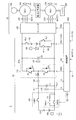
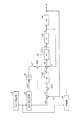
図1は、本発明の実施の形態に従う電源システムが適用される電動車両の概略構成図である。 [Basic configuration of vehicle]
FIG. 1 is a schematic configuration diagram of an electric vehicle to which a power supply system according to an embodiment of the present invention is applied.
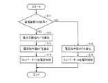
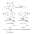
以上のように、本発明の実施の形態による電源システム20では、蓄電装置150が使用される第1のモードと、蓄電装置150が不使用とされる第2のモードとが選択される。この第1および第2のモードのそれぞれについて、制御装置300は、コンバータ110での電圧変換動作を以下のように制御する。 (Converter voltage conversion control)
As described above, in
Pb1+Pb2=Pg+Pm ・・・(1)
蓄電装置100,150が並列に使用される状態では、コンバータ110による蓄電装置100の充放電制御に付随して、蓄電装置150の充放電電力Pb2が定まる。すなわち、蓄電装置150の充放電電力Pb2は成り行きで定まる。そのため、第1のモードでは、制御装置300は、電源システム20から負荷10に供給される電力のうち、蓄電装置100が分担する電力(充放電電力Pb1)を所定の電力目標値Pb1*となるように、コンバータ110を制御する。これにより、蓄電装置100の充放電電力Pb1を任意に調整できるため、間接的に蓄電装置150の充放電電力Pb2についても制御することができる。その結果、蓄電装置100,150を協調的に使用して、モータジェネレータMG1,MG2に電力を供給することが可能となる。 Here, in the first mode in which
Pb1 + Pb2 = Pg + Pm (1)
In a state where
ILfb=ILfb(P)+ILfb(I)
=Kp・ΔIL+Σ(Ki・ΔIL) ・・・(2)
式(2)において、ILfb(P)は比例項であり、ILfb(I)は積分項である。また、ΔILは、今回の制御周期における電流偏差であり、Kp,Kiはフィードバックゲインである。 Specifically, in the control block of FIG. 5, the
ILfb = ILfb (P) + ILfb (I)
= Kp · ΔIL + Σ (Ki · ΔIL) (2)
In Expression (2), ILfb (P) is a proportional term, and ILfb (I) is an integral term. ΔIL is a current deviation in the current control cycle, and Kp and Ki are feedback gains.
Claims (6)
- 負荷(10)に電力を供給する電源システム(20)であって、
第1の蓄電装置(100)と、
第2の蓄電装置(150)と、
前記負荷(10)に対して入出力される電力を伝達するための電力線(HPL)と、
前記第1の蓄電装置(100)と前記電力線(HPL)との間で双方向の直流電圧変換を実行するためのコンバータ(110)と、
前記第2の蓄電装置(150)と前記電力線(HPL)との間に接続された開閉器(RL1)と、
前記開閉器(RL1)のオンオフおよび前記コンバータ(110)を制御する制御装置(300)とを備え、
前記制御装置(300)は、前記開閉器(RL1)のオフ時には、前記電力線(HPL)の電圧値が電圧指令値となるように前記コンバータ(110)を電圧制御する一方で、前記開閉器(RL1)のオン時には、前記第1の蓄電装置(100)の電流値が電流指令値となるように前記コンバータ(110)を電流制御する、電源システム。 A power supply system (20) for supplying power to a load (10),
A first power storage device (100);
A second power storage device (150);
A power line (HPL) for transmitting power to and from the load (10);
A converter (110) for performing bidirectional DC voltage conversion between the first power storage device (100) and the power line (HPL);
A switch (RL1) connected between the second power storage device (150) and the power line (HPL);
A controller (300) for controlling on / off of the switch (RL1) and the converter (110);
When the switch (RL1) is off, the control device (300) controls the voltage of the converter (110) so that the voltage value of the power line (HPL) becomes a voltage command value, while the switch (300) A power supply system that controls the current of the converter (110) so that the current value of the first power storage device (100) becomes a current command value when RL1) is on. - 前記制御装置(300)は、
前記負荷(10)の動作状態に応じて、前記開閉器(RL1)のオンオフを切替える切替部と、
前記電圧指令値に対する前記電力線(HPL)の電圧値の偏差を積分する積分要素を少なくとも含む電圧フィードバック制御要素(24)の出力に応じて、前記コンバータ(110)を電圧制御する電圧制御部と、
前記電流指令値に対する前記第1の蓄電装置(100)の電流値の偏差を積分する積分要素を少なくとも含む電流フィードバック制御要素(16)の出力に応じて、前記コンバータ(110)を電流制御する電流制御部とを含み、
前記電圧制御部は、前記開閉器(RL1)をオンからオフに切替えるときには、前記電圧フィードバック制御要素(24)における積分要素の初期値として、前記電流フィードバック制御要素(16)における積分要素の出力を、前記電流制御部から引き継ぐ、請求項1に記載の電源システム。 The control device (300)
A switching unit that switches on and off of the switch (RL1) according to an operating state of the load (10);
A voltage control unit that controls the voltage of the converter (110) according to an output of a voltage feedback control element (24) including at least an integration element that integrates a deviation of a voltage value of the power line (HPL) with respect to the voltage command value;
A current for controlling the current of the converter (110) according to an output of a current feedback control element (16) including at least an integral element for integrating a deviation of a current value of the first power storage device (100) with respect to the current command value Including a control unit,
When the voltage control unit switches the switch (RL1) from on to off, the output of the integration element in the current feedback control element (16) is used as an initial value of the integration element in the voltage feedback control element (24). The power supply system according to claim 1, taking over from the current control unit. - 前記電流制御部は、前記開閉器(RL1)をオフからオンに切替えるときには、前記電流フィードバック制御要素(16)における積分要素の初期値として、前記電圧フィードバック制御要素(24)における積分要素の出力を、前記電圧制御部から引き継ぐ、請求項2に記載の電源システム。 When switching the switch (RL1) from off to on, the current control unit outputs an output of the integration element in the voltage feedback control element (24) as an initial value of the integration element in the current feedback control element (16). The power supply system according to claim 2, taking over from the voltage control unit.
- 前記電圧制御部は、
前記電圧指令値に対する前記電力線(HPL)の電圧値の偏差を比例積分演算し、算出した制御量を前記電流指令値として出力する電圧制御演算部(440)と、
前記電圧制御演算部(440)から出力される前記電流指令値に対する前記第1の蓄電装置(100)の電流値の偏差を比例積分演算し、算出した制御量を前記コンバータ(110)へのデューティ比指令値として出力する電流制御演算部(442)とを含み、
前記電流制御演算部(442)は、前記開閉器(RL1)のオン時には、前記電圧制御演算部(440)から出力される前記電流指令値に代えて、前記第1の蓄電装置(100)が分担すべき電力目標値に応じて設定された前記電流指令値を受けるように構成されることにより、前記電流制御部として機能する、請求項2または3に記載の電源システム。 The voltage controller is
A voltage control calculation unit (440) that performs a proportional integral calculation of a deviation of the voltage value of the power line (HPL) with respect to the voltage command value, and outputs the calculated control amount as the current command value;
The deviation of the current value of the first power storage device (100) with respect to the current command value output from the voltage control calculation unit (440) is proportional-integral calculated, and the calculated control amount is a duty to the converter (110). A current control calculation unit (442) that outputs as a ratio command value,
When the switch (RL1) is on, the current control calculation unit (442) replaces the current command value output from the voltage control calculation unit (440) with the first power storage device (100). 4. The power supply system according to claim 2, wherein the power supply system functions as the current control unit by being configured to receive the current command value set according to a power target value to be shared. - 前記負荷(10)は、前記電源システム(20)から供給される電力を受けて車両駆動力を発生する電動機(MG2)を含み、
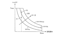
前記電圧制御部は、前記電動機(MG2)のトルクおよび回転数に応じて前記電力線(HPL)の必要最低電圧を算出するとともに、前記必要最低電圧以上の範囲で前記電圧指令値を設定し、
前記電流制御部は、前記電動機(MG2)のトルクおよび回転数に応じて前記電動機(MG2)の必要電力を算出するとともに、前記電動機(MG2)の必要電力に応じて前記第1の蓄電装置(100)が分担すべき電力目標値を決定し、かつ、前記電力目標値を前記第1の蓄電装置(100)の電圧で除算することにより記電流目標値を設定する、請求項1に記載の電源システム。 The load (10) includes an electric motor (MG2) that receives electric power supplied from the power supply system (20) and generates vehicle driving force,
The voltage control unit calculates a necessary minimum voltage of the power line (HPL) according to the torque and rotation speed of the electric motor (MG2), and sets the voltage command value in a range equal to or more than the necessary minimum voltage.
The current control unit calculates the required power of the electric motor (MG2) according to the torque and rotation speed of the electric motor (MG2), and also calculates the first power storage device (MG2) according to the required electric power of the electric motor (MG2). 100) determines a power target value to be shared, and sets the current target value by dividing the power target value by the voltage of the first power storage device (100). Power system. - 負荷(10)に電力を供給する電源システム(20)の制御方法であって、
前記電源システム(20)は、
第1の蓄電装置(100)と、
第2の蓄電装置(150)と、
前記負荷(10)に対して入出力される電力を伝達するための電力線(HPL)と、
前記第1の蓄電装置(100)と前記電力線(HPL)との間で双方向の直流電圧変換を実行するためのコンバータ(110)と、
前記2の蓄電装置(150)と前記電力線(HPL)との間に接続された開閉器(RL1)とを含み、
前記制御方法は、
前記開閉器(RL1)のオフ時には、前記電力線(HPL)の電圧値が電圧指令値となるように前記コンバータ(110)を電圧制御するステップと、
前記開閉器(RL1)のオン時には、前記第1の蓄電装置(100)の電流値が電流指令値となるように前記コンバータ(110)を電流制御するステップとを備える、電源システムの制御方法。 A control method for a power supply system (20) for supplying power to a load (10), comprising:
The power supply system (20)
A first power storage device (100);
A second power storage device (150);
A power line (HPL) for transmitting power to and from the load (10);
A converter (110) for performing bidirectional DC voltage conversion between the first power storage device (100) and the power line (HPL);
A switch (RL1) connected between the second power storage device (150) and the power line (HPL);
The control method is:
Voltage-controlling the converter (110) so that the voltage value of the power line (HPL) becomes a voltage command value when the switch (RL1) is off;
And a step of controlling the current of the converter (110) so that the current value of the first power storage device (100) becomes a current command value when the switch (RL1) is on.
Priority Applications (5)
| Application Number | Priority Date | Filing Date | Title |
|---|---|---|---|
| PCT/JP2011/071987 WO2013046314A1 (en) | 2011-09-27 | 2011-09-27 | Power supply system and method for controlling same |
| EP11873344.3A EP2763270B1 (en) | 2011-09-27 | 2011-09-27 | Power supply system and method for controlling same |
| US14/347,102 US9236736B2 (en) | 2011-09-27 | 2011-09-27 | Power supply system and method for controlling the same |
| CN201180073644.8A CN103828173B (en) | 2011-09-27 | 2011-09-27 | Power-supply system and control method thereof |
| JP2013535673A JP5751334B2 (en) | 2011-09-27 | 2011-09-27 | Power supply system and control method thereof |
Applications Claiming Priority (1)
| Application Number | Priority Date | Filing Date | Title |
|---|---|---|---|
| PCT/JP2011/071987 WO2013046314A1 (en) | 2011-09-27 | 2011-09-27 | Power supply system and method for controlling same |
Publications (1)
| Publication Number | Publication Date |
|---|---|
| WO2013046314A1 true WO2013046314A1 (en) | 2013-04-04 |
Family
ID=47994431
Family Applications (1)
| Application Number | Title | Priority Date | Filing Date |
|---|---|---|---|
| PCT/JP2011/071987 WO2013046314A1 (en) | 2011-09-27 | 2011-09-27 | Power supply system and method for controlling same |
Country Status (5)
| Country | Link |
|---|---|
| US (1) | US9236736B2 (en) |
| EP (1) | EP2763270B1 (en) |
| JP (1) | JP5751334B2 (en) |
| CN (1) | CN103828173B (en) |
| WO (1) | WO2013046314A1 (en) |
Cited By (4)
| Publication number | Priority date | Publication date | Assignee | Title |
|---|---|---|---|---|
| WO2015104200A1 (en) * | 2014-01-10 | 2015-07-16 | Robert Bosch Gmbh | Electrochemical composite storage system |
| KR20150109523A (en) * | 2014-03-19 | 2015-10-02 | 삼성전기주식회사 | Power supply device |
| JP2016039675A (en) * | 2014-08-06 | 2016-03-22 | 株式会社デンソー | DCDC converter |
| JP2016111730A (en) * | 2014-12-02 | 2016-06-20 | トヨタ自動車株式会社 | Power supply system |
Families Citing this family (15)
| Publication number | Priority date | Publication date | Assignee | Title |
|---|---|---|---|---|
| US9190899B2 (en) * | 2011-09-28 | 2015-11-17 | General Electric Company | Power factor correction (PFC) circuit configured to control high pulse load current and inrush current |
| US10234830B2 (en) * | 2014-08-08 | 2019-03-19 | Toyo System Co., Ltd. | Feedback control device |
| US9762164B2 (en) * | 2015-09-18 | 2017-09-12 | Faraday & Future Inc. | Methods and apparatus for generating current commands for an interior permanent magnet (IPM) motor |
| US9768719B2 (en) * | 2015-09-18 | 2017-09-19 | Faraday&Future Inc. | Methods and apparatus for generating current commands for an interior permanent magnet (IPM) motor |
| DE102015220223A1 (en) * | 2015-10-16 | 2017-04-20 | Zf Friedrichshafen Ag | Limitation of the current gradient during load shedding |
| JP6458756B2 (en) * | 2016-03-22 | 2019-01-30 | トヨタ自動車株式会社 | Automobile |
| JP6399045B2 (en) * | 2016-06-16 | 2018-10-03 | トヨタ自動車株式会社 | Voltage control system, fuel cell system, and voltage control system control method |
| US10141855B2 (en) | 2017-04-12 | 2018-11-27 | Accion Systems, Inc. | System and method for power conversion |
| JP6790980B2 (en) * | 2017-04-12 | 2020-11-25 | トヨタ自動車株式会社 | Hybrid vehicle and its control method |
| CN111226364B (en) * | 2017-10-17 | 2022-06-28 | 株式会社村田制作所 | Power supply device, power control device, and relay determination method for power supply device |
| WO2019244343A1 (en) * | 2018-06-22 | 2019-12-26 | 三菱電機株式会社 | Drive control device and drive device for railroad cars |
| JP7163714B2 (en) * | 2018-10-18 | 2022-11-01 | トヨタ自動車株式会社 | vehicle power supply |
| US20220014018A1 (en) * | 2019-05-10 | 2022-01-13 | Mitsubishi Electric Corporation | Dc power supply and distribution system |
| US11545351B2 (en) | 2019-05-21 | 2023-01-03 | Accion Systems, Inc. | Apparatus for electrospray emission |
| JP7436783B2 (en) * | 2019-09-30 | 2024-02-22 | ダイキン工業株式会社 | power converter |
Citations (6)
| Publication number | Priority date | Publication date | Assignee | Title |
|---|---|---|---|---|
| JP2007135375A (en) * | 2005-11-14 | 2007-05-31 | Nissan Motor Co Ltd | Controller for dc-dc converter |
| JP2009089536A (en) * | 2007-10-01 | 2009-04-23 | Toyota Motor Corp | Power supply system |
| JP2009159663A (en) | 2007-12-25 | 2009-07-16 | Toyota Motor Corp | Motor drive device, electric vehicle, and method of controlling motor drive devices |
| JP2010206912A (en) | 2009-03-03 | 2010-09-16 | Hitachi Koki Co Ltd | Charger |
| JP2010288346A (en) | 2009-06-10 | 2010-12-24 | Toyota Motor Corp | Power supply system for electric vehicle, and the electric vehicle |
| JP2011125144A (en) * | 2009-12-10 | 2011-06-23 | Toyota Motor Corp | Control device of converter |
Family Cites Families (7)
| Publication number | Priority date | Publication date | Assignee | Title |
|---|---|---|---|---|
| JPH08223907A (en) | 1995-02-06 | 1996-08-30 | Internatl Business Mach Corp <Ibm> | Power unit and power supply supplying method |
| JP4978082B2 (en) * | 2006-03-31 | 2012-07-18 | トヨタ自動車株式会社 | Power supply system and vehicle equipped with the same |
| JP4569603B2 (en) | 2007-01-04 | 2010-10-27 | トヨタ自動車株式会社 | Power supply system, vehicle including the same, and control method thereof |
| JP4380772B2 (en) * | 2007-10-16 | 2009-12-09 | トヨタ自動車株式会社 | POWER SUPPLY DEVICE, VEHICLE EQUIPPED WITH THE SAME, CONTROL METHOD FOR POWER SUPPLY DEVICE, AND COMPUTER-READABLE RECORDING MEDIUM CONTAINING PROGRAM FOR CAUSING COMPUTER TO EXECUTE THE CONTROL METHOD |
| US8544576B2 (en) * | 2007-12-26 | 2013-10-01 | Sumitomo Heavy Industries, Ltd. | Hybrid construction machine and method of controlling hybrid construction machine |
| JP2010068576A (en) | 2008-09-09 | 2010-03-25 | Toyota Motor Corp | Converter control device |
| US8723490B2 (en) * | 2010-08-30 | 2014-05-13 | Intersil Americas Inc. | Controlling a bidirectional DC-to-DC converter |
-
2011
- 2011-09-27 US US14/347,102 patent/US9236736B2/en active Active
- 2011-09-27 CN CN201180073644.8A patent/CN103828173B/en active Active
- 2011-09-27 WO PCT/JP2011/071987 patent/WO2013046314A1/en active Application Filing
- 2011-09-27 JP JP2013535673A patent/JP5751334B2/en active Active
- 2011-09-27 EP EP11873344.3A patent/EP2763270B1/en active Active
Patent Citations (6)
| Publication number | Priority date | Publication date | Assignee | Title |
|---|---|---|---|---|
| JP2007135375A (en) * | 2005-11-14 | 2007-05-31 | Nissan Motor Co Ltd | Controller for dc-dc converter |
| JP2009089536A (en) * | 2007-10-01 | 2009-04-23 | Toyota Motor Corp | Power supply system |
| JP2009159663A (en) | 2007-12-25 | 2009-07-16 | Toyota Motor Corp | Motor drive device, electric vehicle, and method of controlling motor drive devices |
| JP2010206912A (en) | 2009-03-03 | 2010-09-16 | Hitachi Koki Co Ltd | Charger |
| JP2010288346A (en) | 2009-06-10 | 2010-12-24 | Toyota Motor Corp | Power supply system for electric vehicle, and the electric vehicle |
| JP2011125144A (en) * | 2009-12-10 | 2011-06-23 | Toyota Motor Corp | Control device of converter |
Non-Patent Citations (1)
| Title |
|---|
| See also references of EP2763270A4 * |
Cited By (7)
| Publication number | Priority date | Publication date | Assignee | Title |
|---|---|---|---|---|
| WO2015104200A1 (en) * | 2014-01-10 | 2015-07-16 | Robert Bosch Gmbh | Electrochemical composite storage system |
| CN105873794A (en) * | 2014-01-10 | 2016-08-17 | 罗伯特·博世有限公司 | Electrochemical composite storage system |
| US10232728B2 (en) | 2014-01-10 | 2019-03-19 | Robert Bosch Gmbh | Electrochemical composite storage system |
| KR20150109523A (en) * | 2014-03-19 | 2015-10-02 | 삼성전기주식회사 | Power supply device |
| KR101864466B1 (en) * | 2014-03-19 | 2018-06-05 | 한국과학기술원 | Power supply device |
| JP2016039675A (en) * | 2014-08-06 | 2016-03-22 | 株式会社デンソー | DCDC converter |
| JP2016111730A (en) * | 2014-12-02 | 2016-06-20 | トヨタ自動車株式会社 | Power supply system |
Also Published As
| Publication number | Publication date |
|---|---|
| EP2763270A1 (en) | 2014-08-06 |
| JP5751334B2 (en) | 2015-07-22 |
| CN103828173B (en) | 2016-05-04 |
| CN103828173A (en) | 2014-05-28 |
| EP2763270B1 (en) | 2016-05-25 |
| EP2763270A4 (en) | 2015-02-25 |
| US20140225430A1 (en) | 2014-08-14 |
| US9236736B2 (en) | 2016-01-12 |
| JPWO2013046314A1 (en) | 2015-03-26 |
Similar Documents
| Publication | Publication Date | Title |
|---|---|---|
| JP5751334B2 (en) | Power supply system and control method thereof | |
| US8659182B2 (en) | Power supply system and electric powered vehicle including power supply system, and method for controlling power supply system | |
| US7859201B2 (en) | Charge control apparatus, electrically powered vehicle and electric storage charge control method | |
| US7486034B2 (en) | Power supply device for vehicle and method of controlling the same | |
| US9166515B2 (en) | Electrically powered vehicle and method for controlling the same | |
| US7755306B2 (en) | Electric power control device, electric powered vehicle including the same, and method for controlling electric power of electric vehicle | |
| US8674637B2 (en) | Vehicle | |
| US7969039B2 (en) | Method of controlling fuel cell vehicle and method of controlling DC/DC converter apparatus | |
| US20090314558A1 (en) | Voltage Conversion Apparatus and Vehicle Including the Same | |
| US20120049774A1 (en) | Control device for voltage converter, vehicle equipped with the same, and control method for voltage converter | |
| WO2007026942A1 (en) | Charge controller and electric vehicle | |
| JP2007290483A (en) | Stop control device and stop control method of internal combustion engine | |
| JP5320988B2 (en) | Power supply system and power balance control method thereof | |
| JP2011166990A (en) | Power supply system | |
| JP2013051831A (en) | Power source control device of electric vehicle | |
| JP2019054673A (en) | Power supply apparatus | |
| JP2012110189A (en) | Electric system for motor-driven vehicle and control method therefor | |
| CN108482102B (en) | Hybrid power driving system | |
| JP4590960B2 (en) | Electric motor drive | |
| JP2013055853A (en) | Power supply control device of electric vehicle | |
| JP2013090410A (en) | Electric vehicle | |
| EP2080662B1 (en) | Fuel cell vehicle and DC/DC converter apparatus | |
| JP2017171159A (en) | Hybrid vehicle | |
| JP2013059164A (en) | Power supply control device of electric vehicle | |
| JP2012065479A (en) | Motor drive device and vehicle equipped with the same |
Legal Events
| Date | Code | Title | Description |
|---|---|---|---|
| WWE | Wipo information: entry into national phase |
Ref document number: 201180073644.8 Country of ref document: CN |
|
| 121 | Ep: the epo has been informed by wipo that ep was designated in this application |
Ref document number: 11873344 Country of ref document: EP Kind code of ref document: A1 |
|
| ENP | Entry into the national phase |
Ref document number: 2013535673 Country of ref document: JP Kind code of ref document: A |
|
| WWE | Wipo information: entry into national phase |
Ref document number: 14347102 Country of ref document: US |
|
| NENP | Non-entry into the national phase |
Ref country code: DE |
|
| WWE | Wipo information: entry into national phase |
Ref document number: 2011873344 Country of ref document: EP |