WO2012147760A1 - Inkjet recording device - Google Patents
Inkjet recording device Download PDFInfo
- Publication number
- WO2012147760A1 WO2012147760A1 PCT/JP2012/061024 JP2012061024W WO2012147760A1 WO 2012147760 A1 WO2012147760 A1 WO 2012147760A1 JP 2012061024 W JP2012061024 W JP 2012061024W WO 2012147760 A1 WO2012147760 A1 WO 2012147760A1
- Authority
- WO
- WIPO (PCT)
- Prior art keywords
- recording medium
- ink
- suction hole
- temperature
- holding layer
- Prior art date
Links
Images


Classifications
-
- B—PERFORMING OPERATIONS; TRANSPORTING
- B41—PRINTING; LINING MACHINES; TYPEWRITERS; STAMPS
- B41J—TYPEWRITERS; SELECTIVE PRINTING MECHANISMS, i.e. MECHANISMS PRINTING OTHERWISE THAN FROM A FORME; CORRECTION OF TYPOGRAPHICAL ERRORS
- B41J11/00—Devices or arrangements of selective printing mechanisms, e.g. ink-jet printers or thermal printers, for supporting or handling copy material in sheet or web form
- B41J11/0085—Using suction for maintaining printing material flat
-
- B—PERFORMING OPERATIONS; TRANSPORTING
- B41—PRINTING; LINING MACHINES; TYPEWRITERS; STAMPS
- B41J—TYPEWRITERS; SELECTIVE PRINTING MECHANISMS, i.e. MECHANISMS PRINTING OTHERWISE THAN FROM A FORME; CORRECTION OF TYPOGRAPHICAL ERRORS
- B41J11/00—Devices or arrangements of selective printing mechanisms, e.g. ink-jet printers or thermal printers, for supporting or handling copy material in sheet or web form
- B41J11/0015—Devices or arrangements of selective printing mechanisms, e.g. ink-jet printers or thermal printers, for supporting or handling copy material in sheet or web form for treating before, during or after printing or for uniform coating or laminating the copy material before or after printing
- B41J11/002—Curing or drying the ink on the copy materials, e.g. by heating or irradiating
- B41J11/0021—Curing or drying the ink on the copy materials, e.g. by heating or irradiating using irradiation
- B41J11/00214—Curing or drying the ink on the copy materials, e.g. by heating or irradiating using irradiation using UV radiation
-
- B—PERFORMING OPERATIONS; TRANSPORTING
- B41—PRINTING; LINING MACHINES; TYPEWRITERS; STAMPS
- B41J—TYPEWRITERS; SELECTIVE PRINTING MECHANISMS, i.e. MECHANISMS PRINTING OTHERWISE THAN FROM A FORME; CORRECTION OF TYPOGRAPHICAL ERRORS
- B41J11/00—Devices or arrangements of selective printing mechanisms, e.g. ink-jet printers or thermal printers, for supporting or handling copy material in sheet or web form
- B41J11/02—Platens
- B41J11/06—Flat page-size platens or smaller flat platens having a greater size than line-size platens
Definitions
- the present invention relates to an ink jet recording apparatus.
- inkjet recording methods are capable of recording high-definition images with a relatively simple apparatus, and have been rapidly developed in various fields.
- a recording medium or ink suitable for each purpose is used.
- the recording speed has been greatly improved, and development of an ink jet recording apparatus having performance capable of withstanding light printing applications is also progressing.
- the ink preferably has a relatively low viscosity.
- ink having a relatively low viscosity is emitted and landed on a recording medium, there is the following problem of image quality degradation.
- the ink has temperature sensitivity, and a temperature difference is provided between the ink jet recording head and the recording medium.
- a temperature-sensitive thickening type ink that attempts to prevent bleeding, beading, feathering, and the like while ensuring high emissivity when landing on a recording medium.
- a technique has been developed in which an ink made of a substance that forms a solid resinous material by cooling after being heated at room temperature and the nozzles of the recording head are heated above the temperature at which the ink solidifies. (For example, refer to Patent Document 1).
- the present invention has been made in view of the above problems in the prior art, and is an adsorption hole that contacts a recording medium in an ink jet recording apparatus using an ink that changes in phase from a gel state or a solid state to a liquid state depending on temperature.
- a recording medium fixing means for adsorbing and fixing a recording medium by air suction via a suction hole it is an object to prevent the pattern of the suction holes from being raised in the image.
- the invention according to claim 1 is an ink jet recording apparatus using an ink that changes in phase between a gel or a solid and a liquid depending on a temperature.
- a recording medium fixing means for adsorbing and fixing the recording medium by air suction through an adsorption hole in contact with the recording medium; Negative pressure generating means for generating a negative pressure for air suction;
- An ink jet recording head for discharging the liquid ink to the recording medium;
- the recording medium fixing means includes A recording medium holding layer in which the suction hole is formed and the ink is held at a temperature at which the ink becomes a gel or solid;
- a support layer that includes at least one layer that supports the recording medium holding layer, and has a suction hole that communicates with the suction hole.
- an opening area of an opening end of the suction hole in contact with the recording medium is smaller than an opening area of an opening end of the suction hole in contact with the recording medium holding layer.
- the diameter D of the maximum circle that fits within the opening of the suction hole that is in contact with the recording medium satisfies the relationship of D ⁇ 4t with respect to the thickness t of the recording medium.
- the invention described in claim 3 is characterized in that an aperture ratio represented by an opening area of the suction hole occupying a surface area of the recording medium holding layer in contact with the recording medium is 5% or more and 75% or less.
- the thickness of the recording medium holding layer is 0.05 mm or more and 0.4 mm or less, and the ink jet recording apparatus according to any one of the first to third aspects. It is.
- the invention according to claim 5 is the ink jet recording apparatus according to any one of claims 1 to 4, wherein a material of the recording medium holding layer is stainless steel.
- the invention according to claim 6 is the ink jet recording apparatus according to any one of claims 1 to 5, further comprising heating means for heating the recording medium fixing means to a predetermined temperature.
- the invention according to claim 7 is the ink jet recording apparatus according to any one of claims 1 to 6, wherein the recording medium has a thickness of 0.15 mm or less.
- the perforation diameter depends on the thickness in the perforation direction, and the smaller the thickness, the smaller the hole can be perforated, but the rigidity of the member decreases.
- FIG. 1 is a schematic diagram illustrating a main configuration of an ink jet recording apparatus according to an embodiment of the present invention.
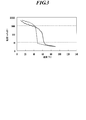
- FIG. 2 is a schematic diagram illustrating a recording medium fixing unit, a suction pump, and a pipe connecting the recording medium fixing unit and the suction pump included in the ink jet recording apparatus according to the embodiment of the present invention, including the recording medium. It is a graph which shows an example of the temperature-viscosity characteristic of gelled ink.
- FIG. 3 is a partial plan view illustrating a part of the recording medium holding layer and the support layer according to an embodiment of the present invention.
- FIG. 3 is a cross-sectional view taken along line AA of a partial plan view showing a part of the recording medium holding layer and the support layer according to an embodiment of the present invention.
- FIG. 6 is a cross-sectional view taken along line BB of a partial plan view in which a part of the region showing a recording medium holding layer and a support layer according to a comparative example is extracted and drawn. It is a graph which shows the temperature change of the ink surface which concerns on a comparative example. It is a graph which shows the temperature change of the ink surface which concerns on an example of this invention. It is a top view which shows the example of a planar shape of the suction hole applicable to this invention.
- FIG. 5 is a partial plan view illustrating a part of a recording medium holding layer and a support layer according to another embodiment of the present invention.
- FIG. 6 is a cross-sectional view taken along line CC of a partial plan view illustrating a part of the recording medium holding layer and the support layer according to another embodiment of the present invention.
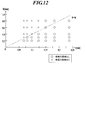
- 5 is a graph showing whether or not a suction hole pattern is generated, with the horizontal axis representing the thickness t of the recording medium and the vertical axis representing the diameter D of the maximum circle that fits within the opening at the opening end of the suction hole contacting the recording medium.
- 5 is a graph showing whether or not a suction hole pattern is generated, with the horizontal axis representing the thickness t of the recording medium and the vertical axis representing the diameter D of the maximum circle that fits within the opening at the opening end of the suction hole contacting the recording medium.
- FIG. 3 is a partial cross-sectional view of a recording medium, a recording medium holding layer, and a support layer, schematically showing air flow paths during suction with arrows.
- the ink jet recording apparatus 1 uses a temperature-sensitive and thick ink that changes in phase from gel or solid to liquid according to temperature.
- an ink jet recording apparatus 1 according to this embodiment includes a recording medium fixing means 2 for adsorbing and fixing a recording medium M, a suction pump 3 as a negative pressure generating means, an ink jet recording head 41, and a light irradiation means.
- a paper feed tray 51 for storing the recording medium M for storing the recording medium M
- a moving device 53 for the recording medium fixing means 2 for the recording medium fixing means 2
- a recording medium A transport device 54 that transports the recording medium M from the fixing means 2 to the paper discharge tray 55, a suction operation of the paper discharge tray 55 and the suction pump 3, a recording operation of the ink jet recording head 41, lighting of the light irradiation means 42, a transport device 52 and 54 and a control device (not shown) for controlling the entire apparatus including the transfer operation of the moving device 53.
- FIG. 2 shows a schematic diagram of the recording medium M, the recording medium fixing means 2, the suction pump 3, and the piping 31 connecting them.
- the recording medium M, the recording medium fixing means 2 and the pipe 31 are shown in cross section.
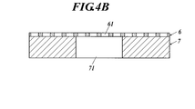
- the recording medium fixing means 2 supports the recording medium holding layer 6 and the recording medium holding layer 6 in which the suction holes 61 are formed and the ink is held at a temperature at which the ink becomes gel or solid.
- As the recording medium holding layer 6, a thin plate having a suction hole 61 perforated is mainly used.
- the support layer 7 has a structure having an internal space 72, and the support layer 7 is formed with suction holes 71 that communicate with the suction holes 61 from the internal space 72.
- the internal space 72 is connected to the suction pump 3 via the pipe 31.
- the recording medium M is sucked through the pipe 31, the internal space 72, and further the suction hole 71 and the suction hole 61, and the recording medium M is sucked into the suction hole on the surface of the recording medium holding layer 6.
- the temperature of the ink in the inkjet recording head 41 is adjusted so as to maintain a liquid state. Further, heating means for heating the recording medium fixing means 2 to a predetermined temperature is provided. This is to change the temperature of the ink that has landed on the recording medium M on the recording medium fixing means 2 to a gel or solid state.
- a heater such as a heating wire arranged in contact with the recording medium fixing means 2 or an infrared lamp for heating in a non-contact manner is used.
- an image is formed by ejecting liquid ink from the inkjet recording head 41 to the recording medium M adsorbed and fixed on the recording medium holding layer 6.
- the ink ejected from the ink jet recording head 41 is landed on the recording medium M, and becomes gelled or solidified and fixed on the recording medium M by lowering the temperature from the temperature at the time of ejection.
- An example of the temperature-viscosity characteristics of the gelled ink that gels at this time is shown in FIG.
- This gelled ink has a viscosity of 10 [mPa seconds] or less at an ink temperature of 80 ° C. or higher, but once it drops to a room temperature level (20 to 30 ° C.), the viscosity becomes several thousand [mPa seconds].
- the recording medium holding layer 6 in which a number of minute suction holes 61 are formed from the suction holes 71 of the support layer 7 contributes to the effect of preventing the pattern of the suction holes from appearing in the image.
- one suction hole 61 formed in the recording medium holding layer 6 has an opening area (upper end in FIG. 4B) in contact with the recording medium M, and the recording medium holding of one suction hole 71. The opening area is smaller than the opening area in contact with the layer 6.
- a large number of such minute suction holes 61 are formed in the recording medium holding layer 6 at substantially equal intervals.
- a region overlapping the suction hole 71 and a peripheral region of the suction hole 71 are included. Distributed.
- a large number of suction holes 71 are also distributed in the vertical and horizontal directions, and the structure shown in FIG.
- a member that forms the suction hole 61 and a member that forms the suction hole 71 may be overlapped, or a portion that becomes the recording medium holding layer 6 and the support layer 7 from before the suction hole 61 and the suction hole 71 are processed. Is formed by forming a relatively small hole as the suction hole 61 on one surface in contact with the recording medium M and forming a large hole as the suction hole 71 from the opposite surface. Good.
- the adsorption force on the surface on which the recording medium M in which the adsorption hole 61 is opened can be expressed by (total opening area) ⁇ (adsorption pressure).
- the suction force can be increased by increasing the ratio of the area occupied by the suction holes 61 in the region covered with the recording medium M, that is, the aperture ratio.
- increasing the area of each suction hole 61 makes it easier for the pattern of the suction hole to appear in the image, so that it is possible to increase the suction force while preventing the pattern of the suction hole from appearing in the image. It is necessary to form a larger number of fine suction holes and arrange them at high density.
- the recording medium holding layer 6 and the support layer 7 are separated, the following advantages are obtained. For example, it is highly difficult to form a large number of micro holes of less than ⁇ 1.0 mm, specifically ⁇ 0.4 mm, on an aluminum plate having a thickness of 5 mm. Since the adsorption force is determined by the aperture ratio and the adsorption pressure, it is necessary to increase the number of holes as the hole diameter is smaller in order to ensure an appropriate aperture ratio. When drilling micro holes in the support layer 7 having a thickness of about 5 mm, the micro holes must be drilled one by one, and a burr treatment is required for each hole. It will take.
- the recording medium holding layer 6 is made of a thin plate, specifically, a stainless steel having a thickness of 0.1 mm, it is possible to make a large number of ⁇ 0.4 mm or even smaller holes by etching at the same time, and no burr treatment is required. Can be manufactured at cost.
- the support layer 7 in which the suction hole 71 of ⁇ 1.0 mm is opened in 5 mm thick aluminum Furthermore, an OK top coat with a thickness of 0.056 mm (basis weight 73.3 gsm) is applied to the recording medium fixing means in which the recording medium holding layer 6 having a ⁇ 1.0 mm suction hole 62 is provided on 0.1 mm thick stainless steel.
- the graph of FIG. 6 shows the temperature change of the ink surface when an image is formed by ink jetting with + (Oji Paper) adsorbed as a recording medium.
- FIG. 6 shows the change in the ink surface temperature (contact portion, solid line graph) located at a position sufficiently away from the ⁇ 1.0 hole, in this example, 2 mm away.
- the recording medium M and the recording medium fixing means are heated to 45 ° C. in order to obtain a suitable gloss.
- the temperature difference between the hole (dashed line) and the contact (solid line) reaches 4.0 ° C. at the maximum.
- the difference in ink temperature decrease history between the hole and the contact portion is that there is no suction hole 62 below the recording medium M in the contact portion, and a member such as a metal having good thermal conductivity around the suction hole 62.
- a member such as a metal having good thermal conductivity around the suction hole 62.
- the ink temperature is difficult to escape because air is below the recording medium M in the hole.
- the difference in thermal conductivity between the hole (that is, air) and the contact portion (that is, metal) is 640 times even in the case of SUS304, which is sufficiently large.
- the recording medium holding layer 6 is made of stainless steel, carbon steel, or aluminum, the difference in ink temperature drop between the hole and the contact portion is the same.
- the support layer 7 having a suction hole 71 of ⁇ 1.0 mm in aluminum having a thickness of 5 mm is adsorbed by ⁇ 0.4 mm to a stainless steel having a thickness of 0.1 mm.
- an OK top coat + (Oji Paper) having a thickness of 0.056 mm (basis weight 73.3 gsm) is adsorbed as the recording medium.
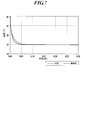
- FIG. 7 is a graph showing temperature changes on the ink surface when an image is formed by inkjet. Other conditions are the same as in the graph of FIG. As shown in the graph of FIG.
- the maximum temperature difference between the hole and the contact portion is 1.4 ° C., and it can be seen that the temperature difference between the hole and the contact portion is smaller than that in the graph of FIG.
- the difference between the graphs in FIGS. 6 and 7 is due to the difference in the suction hole diameter of the recording medium holding layer 6.
- the suction hole diameter of the recording medium holding layer 6 is ⁇ 1.0 mm, the pattern of the suction hole appears in the formed image, but when the suction hole diameter of the recording medium holding layer 6 is ⁇ 0.4 mm, it is formed. There is no suction hole pattern in the image.
- the opening shape of the suction hole formed in the recording medium holding layer 6 is not limited to the circle shown in FIG.
- the shape may be a square, hexagon, cross, or the like. However, it is preferable to satisfy the following conditions.
- the diameter D is defined with reference to FIG. Since the suction hole 61a shown in FIG. 8A has a circular shape, the diameter D of the circle with the largest area that can be accommodated in the opening is equal to the diameter of the suction hole 61a.
- the suction hole is not circular, for example, in the suction hole 61b shown in FIG. 8B and the suction hole 61c shown in FIG.
- the circle indicated by the alternate long and short dash line is the maximum circle that can be accommodated inside the opening.
- the diameter of the circle is defined as D.
- the opening shape of the suction hole is preferably a shape in which the corner portion is rounded because stress concentrates on the corner portion if there is a corner shape.
- the cross-sectional shape of the suction hole is not limited to a columnar shape.
- the cross-sectional shape is a straight hole shape with a constant diameter like the suction hole 61a shown in FIG. 9A, or a tapered shape like the suction hole 61d shown in FIG. 9B.
- Various shapes such as a shape that expands at both ends, such as the suction hole 61e shown, can be adopted. In the case of the suction holes 61d and 61e, it is the diameter D of the maximum circle that fits in the opening at the opening end that contacts the recording medium.
- the suction hole 71 of the support layer 7 is not limited to the one having only the straight hole shown in FIG. 4, and the suction hole 71b in contact with the lower hole 71a and the recording medium holding layer 6 as shown in FIG.
- the structure which consists of can also be taken.
- the opening area of the suction hole 71 provided in the support layer 7 is the surface of the support layer 7 in contact with the recording medium holding layer 6. It refers to the opening area of the suction groove 71b that opens.
- FIGS. 11 and 12 show the suction hole pattern when the recording medium holding layer 6 is made of stainless steel having a thickness of 0.1 mm, and the suction holes 61 are arranged at a pitch of 1.5D and a 60 ° staggered arrangement (aperture ratio 40.3%). It is an evaluation result of the presence or absence of occurrence.
- OK top coat + (Oji Paper) was used as the recording medium M.
- npi fine quality (Nippon Paper Industries) was used as the recording medium M.
- the generation of the suction hole pattern can be prevented when the diameter D satisfies the relationship of D ⁇ 4t. . This is to reduce the temperature unevenness that occurs in the ink between the hole and the contact portion by reducing the distance from the hole on the center of the suction hole 61 of the recording medium M to the contact portion with the recording medium holding layer 6.
- the thinner the recording medium the smaller the distance between the recording medium holding layer 6 and the ink on the recording medium M, and the more likely the temperature unevenness occurs. Therefore, the thinner the recording medium, the smaller the diameter D needs to be.
- the thicker the recording medium M the greater the distance between the recording medium holding layer 6 and the ink on the recording medium M and the greater the heat insulation effect of the recording medium M, so that the ink temperature unevenness is reduced.
- the present invention can be effectively applied to an ink jet recording apparatus in which the thickness of the recording medium M is 0.15 mm or less.
- the opening ratio of the suction holes 61 can be set by the suction hole diameter, hole shape, hole pitch, and hole arrangement. It is preferable to determine the opening ratio represented by the opening area of the suction holes 61 occupying the surface area of the recording medium holding layer 6 in contact with the recording medium M within a range of 5% to 75%. If the aperture ratio is less than 5%, the recording medium cannot be adsorbed with a sufficient adsorbing force. If the aperture ratio exceeds 75%, the adsorbing force can be secured, but the recording medium holding layer is deformed due to insufficient rigidity. This is because there is a concern that temperature unevenness between the hole portion and the contact portion may not be sufficiently reduced because the contact portion is less than 25% and becomes local. More preferably, the aperture ratio is 10% or more and 50% or less.
- the arrangement of the suction holes 61 is not particularly limited, but a 60 ° staggered arrangement is preferable in order to arrange a large number of suction holes 61 at a high density.
- the adsorptive power was measured as follows. Thickness in which holes of ⁇ 1.0 mm are opened in a 60 ° staggered arrangement with a pitch of 6 mm as suction holes 71 and holes of ⁇ 0.2 mm are opened in a 60 ° staggered arrangement with a pitch of 0.3 mm as suction holes 71.
- a stainless steel recording medium holding layer 6 having a thickness of 0.1 mm was placed, and when a 100 mm ⁇ 297 mm size paper as the recording medium M was adsorbed at a negative pressure of 50 kPa, the paper peeling force was measured with a pull gauge. The measurement result of the peeling force was 180N.
- the peeling force was measured to be 112 N.
- the aperture ratio with respect to the recording medium decreases.
- the suction force increases when the recording medium holding layer 6 is inserted.
- the suction hole 61 that does not overlap the suction hole 71 of the support layer 7 also exerts an action of adsorbing the recording medium M due to an air leak between the recording medium holding layer 6 and the support layer 7. It is thought that it was because.
- the recording medium holding layer 6 is not integrated with the support layer 7, and the recording medium holding layer 6 is laminated on the support layer 7 between these layers. In order to obtain a high adsorption force, it is effective that the air leakage is enabled by the suction by the suction pump 3.
- the suction holes 61 As a method of forming the suction holes 61, since it is required to make a large number of small suction holes 61, it is preferable to manufacture them by etching or laser processing in consideration of productivity. In the case of etching processing, since it is basically impossible to make a hole with a pattern smaller than the plate thickness, it is necessary to make the plate thickness smaller than the suction hole diameter. Since the suction hole diameter of the recording medium holding layer 6 is preferably 0.4 mm or less, the plate thickness is preferably 0.4 mm or less. In the case of laser processing, when the plate thickness increases, drilling becomes difficult, and even when the hole is drilled, the taper becomes tight and the aperture ratio of the suction hole 61 cannot be increased.
- the thickness of the recording medium holding layer 6 needs to be 0.05 mm or more.
- the rigidity may be insufficient even if the opening ratio of the suction holes 61 is low.
- the heat capacity of the recording medium holding layer 6 is insufficient, and the temperature change of the recording medium holding layer 6 during ink jet recording becomes large, resulting in a temperature difference between the hole and the contact portion. There is a concern that it may expand and cause a suction hole pattern.
- the ratio of the heat capacity per unit area between the recording medium and the recording medium holding layer is preferably about 1: 4 to 1:10.
- the heat capacity per unit area is 1862 [J / (m 2 ⁇ K)] at a thickness of 0.4 mm, and the heat capacity per unit area is 204 [J / (m) at a thickness of 0.05 mm. 2 ⁇ K)].
- the heat capacity per unit area is 102 [J / (m 2 ⁇ K)].
- the material of the recording medium holding layer 6 is preferably stainless steel from the viewpoint of ensuring the rigidity of the recording medium holding layer 6 while realizing an appropriate suction hole shape and aperture ratio.
- the suction hole shape, the hole area ratio, and the thickness are set in consideration of the flexibility and rigidity of the material used and the fatigue limit.
- Aluminum A5052 has a tensile strength of 230 [N / mm 2 ]
- stainless steel SUS304 has a tensile strength of 520 [N / mm 2 ]. Since the recording medium holding layer 6 repeatedly adsorbs and discharges the recording medium M, it is necessary to pay attention to a decrease in mechanical strength due to repeated stress.
- Stainless steel has a fatigue limit for repeated stress, but aluminum does not have a clear fatigue limit. If the number of repeated stresses is increased, the breaking stress decreases. Therefore, from this point of view, the recording medium holding layer 6 is made of stainless steel. Is preferred.
- the present invention is not limited to the case where the recording medium holding layer 6 and the support layer 7 are flat, and the effect can be obtained even if the recording medium holding layer 6 and the support layer 7 are curved.
- the effect of the present invention can also be obtained by applying a drum for holding and transporting a recording medium and forming the peripheral surface of the drum with the recording medium holding layer 6 to carry out the present invention.
- an actinic ray curable ink that cures when irradiated with energy rays can be suitably applied.
- This actinic ray curable ink contains 1% by mass or more and less than 10% by mass of a gelling agent, and is characterized by reversible sol-gel phase transition depending on temperature.
- the sol-gel phase transition is a solution state with fluidity at high temperatures, but when cooled below the gelation temperature, the entire liquid gels and changes to a state in which it loses fluidity, and conversely loses fluidity at low temperatures. This refers to a phenomenon that returns to a fluid state with fluidity when heated to a temperature equal to or higher than the solation temperature.
- gelation is an interaction such as a lamellar structure, a polymer network formed by non-covalent bonds or hydrogen bonds, a polymer network formed by a physical aggregation state, and an aggregate structure of fine particles.
- solification refers to a state in which the interaction formed by the gelation is eliminated and the liquid state is changed to a fluid state.
- the solation temperature is a temperature at which fluidity develops when the gelled ink is heated, and the gelation temperature is when the ink in the sol state is cooled.
- the sol-gel phase transition actinic ray curable ink is in a liquid state at a high temperature, it can be ejected by an ink jet recording head.
- the ink is quickly cooled by natural cooling due to the temperature difference, and as a result, adjacent dots are coalesced. Can prevent image quality deterioration.
- the solidification force of the ink droplet is strong, the dots are isolated, resulting in unevenness in the image area, which may lead to an uneven glossiness such as an extremely low glossiness or an unnatural sparkle.
- an ink containing 0.1% by mass or more and less than 10% by mass of a gelling agent uses an ink having a viscosity at 25 ° C.
- the temperature control range of the medium corresponds to 42 to 48 ° C.
- the said base material temperature range is used by using the ink in which the viscosity in 25 degreeC of the ink containing 0.1 mass% or more and less than 10 mass% of gelling agents is 10 ⁇ 2 > mPa * s or more and less than 10 ⁇ 5 > mPa * s.
- Viscosity control is possible, and both image quality and natural gloss can be achieved. The reason is presumed as follows. With an ink having a viscosity at 25 ° C. of less than 10 2 mPa ⁇ s, the viscosity is insufficient to prevent liquid coalescence, and the image quality deteriorates in the above temperature range. In addition, with an ink having a viscosity at 25 ° C.
- the viscosity after gelation is high, and the viscosity tends to increase greatly during the cooling process, and the viscosity is controlled to an appropriate level in the above temperature range. This makes it difficult to achieve gloss reduction.
- it becomes a viscous gel with an appropriate viscosity after gelation it is possible to suppress the solidification force of dots more appropriately, and as a result, it is thought that an image with more natural gloss can be obtained. Yes.
- the gloss homogeneity does not mean an absolute gloss value, for example, a 60-degree specular gloss value, but an unnatural glitter or unnecessary gloss caused by a microscopic gloss difference on the image.
- actinic ray curable ink the difference between the ink gel temperature (Tgel) and the surface temperature (Ts) of the recording medium is adjusted to 5 to 15 ° C. An image with excellent sharpness and natural glossiness can be formed, but a better image can be formed by adjusting the temperature of the recording medium in the range of 5 to 10 ° C. It becomes.
- Gelation refers to interactions such as lamellar structures, polymer networks formed by non-covalent bonds and hydrogen bonds, polymer networks formed by physical aggregation, and aggregated structures of fine particles. It refers to a structure in which substances lose their independent movement due to action or the like, and indicate a solidified, semi-solidified, or thickened state with a sudden increase in viscosity or elasticity.
- a gel becomes a fluid solution (sometimes called a sol) by heating, and a thermoreversible gel that returns to the original gel when cooled. There is a heat irreversible gel that does not return.
- the gel formed by the oil gelling agent is preferably a thermoreversible gel from the viewpoint of preventing clogging in the head.
- the gelation temperature (phase transition temperature) of the ink is preferably 40 ° C. or higher and lower than 100 ° C., more preferably 45 ° C. or higher and 70 ° C. or lower.
- the phase transition temperature of the ink is 40 ° C. or higher, stable ejection characteristics can be obtained without being affected by the printing environment temperature when ejecting ink droplets from the recording head. If the temperature is less than 90 ° C., it is not necessary to heat the inkjet recording apparatus to an excessively high temperature, and the load on the head of the inkjet recording apparatus and the members of the ink supply system can be reduced.
- the gelation temperature refers to the temperature at which the viscosity suddenly changes from a fluid solution state to a gel state.
- Gel transition temperature, gel dissolution temperature, phase transition temperature, sol-gel phase transition temperature, gel It is synonymous with a term called a conversion point.
- the method for measuring the gelation temperature of the ink is, for example, using various rheometers (for example, a stress control type rheometer using a cone plate, Physica MCR series, manufactured by Anton Paar), and hot ink in a sol state at a low shear rate. It can be determined from a viscosity curve obtained while changing the temperature and a viscoelastic curve obtained by measuring the temperature change of dynamic viscoelasticity.
- a method in which a small iron piece sealed in a glass tube is placed in a dilatometer and a phase transition point is defined as a point at which the ink liquid does not naturally fall in response to a temperature change J. Polym. Sci., 21, 57 (1956)
- a method of measuring the temperature at which an aluminum cylinder naturally falls when an aluminum cylinder is placed on the ink and changing the gel temperature as a gelation temperature Journal of Japanese Society of Rheology, Vol. 17, 86 ( 1989)
- a gel-like test piece is placed on a heat plate, the heat plate is heated, the temperature at which the shape of the test piece collapses is measured, and this can be obtained as the gelation temperature.
- the gelation temperature (phase transition temperature) of the ink can be adjusted by changing the type of gelling agent used, the amount of gelling agent added, and the type of actinic ray curable monomer.
- the viscosity at 25 ° C. of the ink is preferably 10 2 mPa ⁇ s or more and less than 10 5 mPa ⁇ s, more preferably 10 3 mPa ⁇ s or more and less than 10 4 mPa ⁇ s. is there. If the ink viscosity is 10 2 mPa ⁇ s or more, deterioration of image quality due to dot coalescence can be prevented, and if it is less than 10 5 mPa ⁇ s, by controlling the surface temperature of the recording medium upon ink landing, A uniform gloss can be obtained by appropriate leveling.
- the viscosity of the ink can be appropriately adjusted by changing the type of gelling agent used, the amount of gelling agent added, and the type of actinic ray curable monomer.
- the ink viscosity was measured at a shear rate of 11.7 s ⁇ 1 using a stress-controlled rheometer using a cone plate, Physica MCR series, manufactured by Anton Paar).
- the gelling agent used in the ink may be a high molecular compound or a low molecular compound, but a low molecular compound is preferable from the viewpoint of ink jetting properties.
- the gelling agent that can be used in the ink according to the present invention are shown below, but the present invention is not limited only to these compounds.
- Specific examples of the polymer compound preferably used in the present invention include fatty acid inulins such as inulin stearate, fatty acid dextrins such as dextrin palmitate and dextrin myristate (available from Chiba Flour as the Leopard series), eicosane behenate Examples include glyceryl diacid, eicosane behenate polyglyceryl (available from Nisshin Oilio as Nomcoat series), and the like.
- low molecular weight compound preferably used in the present invention include, for example, low molecular weight oil gelling agents described in JP-A-2005-126507, JP-A-2005-255821 and JP-A-2010-1111790, N -Lauroyl-L-glutamic acid dibutylamide, N-2 ethylhexanoyl-L-glutamic acid dibutylamide and other amide compounds (available from Ajinomoto Finetechno), 1,3: 2,4-bis-O-benzylidene-D -Dibenzylidene sorbitols such as Glucitol (available from Gelol D Shin Nippon Rika), petroleum waxes such as paraffin wax, microcrystalline wax, petrolactam, candelilla wax, carnauba wax, rice wax, wood wax, Jojoba oil, jojoba solid wax, ho Plant waxes such as hover esters, animal waxes such as beeswax, lanolin and whale
- the ink contains a gelling agent, the ink immediately enters the gel state after being ejected from the ink jet recording head, and the mixing of dots and the coalescence of dots are suppressed.
- Image quality can be formed, and then cured by irradiation with actinic rays to be fixed on the recording medium to form a strong image film.
- content of a gelatinizer 1 mass% or more and less than 10 mass% are preferable, and 2 mass% or more and less than 7 mass% are more preferable.
- the actinic ray curable ink contains an actinic ray curable composition that cures with actinic rays together with a gelling agent and a coloring material.
- This actinic ray curable composition (hereinafter also referred to as a photopolymerizable compound) will be described.
- actinic rays include electron beams, ultraviolet rays, ⁇ rays, ⁇ rays, and X-rays.
- An electron beam is preferred. In the present invention, ultraviolet rays are particularly preferable.
- the photopolymerizable compound that is crosslinked or polymerized by irradiation with actinic rays can be used without particular limitation, but among them, a photocationic polymerizable compound or a photoradical polymerizable compound is preferably used.
- Photo cationic polymerizable compound As the photo cationic polymerizable monomer, various known cationic polymerizable monomers can be used. For example, JP-A-6-9714, JP-A-2001-31892, JP-A-2001-40068, JP-A-2001-55507, JP-A-2001-310938, JP-A-2001-310937, JP-A-2001-220526 Epoxy compounds, vinyl ether compounds, oxetane compounds and the like exemplified in each of the above publications.
- the present invention for the purpose of suppressing shrinkage of the recording medium during ink curing, it contains at least one oxetane compound as a photopolymerizable compound and at least one compound selected from an epoxy compound and a vinyl ether compound. Is preferred.
- a preferable aromatic epoxide is a di- or polyglycidyl ether produced by the reaction of a polyhydric phenol having at least one aromatic nucleus or an alkylene oxide adduct thereof and epichlorohydrin, such as bisphenol A or an alkylene oxide thereof.
- examples thereof include di- or polyglycidyl ethers of adducts, di- or polyglycidyl ethers of hydrogenated bisphenol A or its alkylene oxide adducts, and novolak-type epoxy resins.
- examples of the alkylene oxide include ethylene oxide and propylene oxide.
- cyclohexene oxide or cyclopentene obtained by epoxidizing a compound having at least one cycloalkane ring such as cyclohexene or cyclopentene ring with an appropriate oxidizing agent such as hydrogen peroxide or peracid.
- Oxide-containing compounds are preferred.
- Preferred examples of the aliphatic epoxides include di- or polyglycidyl ethers of aliphatic polyhydric alcohols or alkylene oxide adducts thereof, and typical examples thereof include diglycidyl ether of ethylene glycol, diglycidyl ether of propylene glycol or Diglycidyl ether of alkylene glycol such as diglycidyl ether of 1,6-hexanediol, polyglycidyl ether of polyhydric alcohol such as di- or triglycidyl ether of glycerin or its alkylene oxide adduct, polyethylene glycol or its alkylene oxide adduct Of polyalkylene glycols such as diglycidyl ether, polypropylene glycol or diglycidyl ether of its alkylene oxide adduct Glycidyl ether, and the like.
- examples of the alkylene oxide include ethylene oxide and propylene oxide.
- these epoxides in view of fast curability, aromatic epoxides and alicyclic epoxides are preferable, and alicyclic epoxides are particularly preferable.
- one of the above epoxides may be used alone, or two or more may be used in appropriate combination.
- vinyl ether compound examples include ethylene glycol divinyl ether, diethylene glycol divinyl ether, triethylene glycol divinyl ether, propylene glycol divinyl ether, dipropylene glycol divinyl ether, butanediol divinyl ether, hexanediol divinyl ether, cyclohexanedimethanol divinyl ether, Di- or trivinyl ether compounds such as methylolpropane trivinyl ether, ethyl vinyl ether, n-butyl vinyl ether, isobutyl vinyl ether, octadecyl vinyl ether, cyclohexyl vinyl ether, hydroxybutyl vinyl ether, 2-ethylhexyl vinyl ether, cyclohexane dimethanol monovinyl ether, n-propyl Pills vinyl ether, isopropyl vinyl ether, isopropenyl ether -o- propy
- vinyl ether compounds in consideration of curability, adhesion, and surface hardness, di- or trivinyl ether compounds are preferable, and divinyl ether compounds are particularly preferable.
- one of the above vinyl ether compounds may be used alone, or two or more thereof may be used in appropriate combination.
- the oxetane compound referred to in the present invention is a compound having an oxetane ring, and any known oxetane compound as described in JP-A Nos. 2001-220526 and 2001-310937 can be used.
- the viscosity of the ink composition becomes high, which makes handling difficult, and the glass transition temperature of the ink composition is high. Therefore, the tackiness of the obtained cured product may not be sufficient.
- the compound having an oxetane ring used in the present invention is preferably a compound having 1 to 4 oxetane rings.
- Examples of the compound having an oxetane ring that can be preferably used in the present invention include compounds represented by general formula (1) described in paragraph No. (0089) of JP-A No. 2005-255821 and the same publication.
- the general formula (2), the general formula (7) of the paragraph number (0107), the general formula (8) of the paragraph number (0109), and the general formula of the paragraph number (0166) described in the paragraph number (0092) of The compound represented by (9) etc. can be mentioned.
- Specific examples thereof include the exemplified compounds 1 to 6 described in paragraph numbers (0104) to (0119) and the compounds described in paragraph number (0121) of the publication.
- radically polymerizable monomers can be used as the photoradical polymerizable monomer.
- photocurable materials using photopolymerizable compositions described in JP-A-7-159983, JP-B-7-31399, JP-A-8-224982, and JP-A-10-863 and Cationic polymerization photocurable resins are known.
- photocationic polymerization photocurable resins sensitized to a long wavelength region longer than visible light are disclosed in, for example, JP-A-6-43633. It is disclosed in the Kaihei 8-324137 publication.
- the radical polymerizable compound is a compound having an ethylenically unsaturated bond capable of radical polymerization, and may be any compound as long as it has at least one ethylenically unsaturated bond capable of radical polymerization in the molecule. , Oligomers, polymers and the like having a chemical form. Only one kind of radically polymerizable compound may be used, or two or more kinds thereof may be used in combination at an arbitrary ratio in order to improve desired properties.
- Examples of compounds having an ethylenically unsaturated bond capable of radical polymerization include unsaturated carboxylic acids such as acrylic acid, methacrylic acid, itaconic acid, crotonic acid, isocrotonic acid, maleic acid and their salts, esters, urethanes, amides. And radically polymerizable compounds such as various anhydrides, acrylonitrile, styrene, various unsaturated polyesters, unsaturated polyethers, unsaturated polyamides, and unsaturated urethanes. Any known (meth) acrylate monomer and / or oligomer can be used as the radical polymerizable compound.
- the term “and / or” as used herein means that it may be a monomer or an oligomer, and may further include both. The same applies to the items described below.
- Examples of the compound having a (meth) acrylate group include isoamyl acrylate, stearyl acrylate, lauryl acrylate, octyl acrylate, decyl acrylate, isomyristyl acrylate, isostearyl acrylate, 2-ethylhexyl-diglycol acrylate, and 2-hydroxybutyl acrylate.
- 2-acryloyloxyethyl hexahydrophthalic acid butoxyethyl acrylate, ethoxydiethylene glycol acrylate, methoxydiethylene glycol acrylate, methoxypolyethylene glycol acrylate, methoxypropylene glycol acrylate, phenoxyethyl acrylate, tetrahydrofurfuryl acrylate, isobornyl acrylate, 2- Hydroxyethyl Aqua 2-hydroxypropyl acrylate, 2-hydroxy-3-phenoxypropyl acrylate, 2-acryloyloxyethyl succinic acid, 2-acryloyloxyethyl phthalic acid, 2-acryloyloxyethyl-2-hydroxyethyl-phthalic acid , Lactone-modified flexible acrylate, monofunctional monomer such as t-butylcyclohexyl acrylate, triethylene glycol diacrylate, tetraethylene glycol diacrylate, polyethylene glycol diacrylate,
- polymerizable oligomers can be blended in the same manner as the monomer.
- examples of the polymerizable oligomer include epoxy acrylate, aliphatic urethane acrylate, aromatic urethane acrylate, polyester acrylate, and linear acrylic oligomer.
- isoamyl acrylate, stearyl acrylate, lauryl acrylate, octyl acrylate, decyl acrylate, isomyristyl acrylate are particularly preferred from the viewpoints of sensitization, skin irritation, eye irritation, mutagenicity, toxicity, etc.
- stearyl acrylate lauryl acrylate, isostearyl acrylate, ethoxydiethylene glycol acrylate, isobornyl acrylate, tetraethylene glycol diacrylate, glycerin propoxy triacrylate, cowprolactone-modified trimethylolpropane triacrylate, caprolactam-modified dipenta Erythritol hexaacrylate is particularly preferred.
- a vinyl ether monomer and / or oligomer and a (meth) acrylate monomer and / or oligomer may be used in combination as the polymerizable compound.
- the vinyl ether monomer include ethylene glycol divinyl ether, diethylene glycol divinyl ether, triethylene glycol divinyl ether, propylene glycol divinyl ether, dipropylene glycol divinyl ether, butanediol divinyl ether, hexanediol divinyl ether, cyclohexanedimethanol divinyl ether, Di- or trivinyl ether compounds such as methylolpropane trivinyl ether, ethyl vinyl ether, n-butyl vinyl ether, isobutyl vinyl ether, octadecyl vinyl ether, cyclohexyl vinyl ether, hydroxybutyl vinyl ether, 2-ethylhexyl
- a bifunctional vinyl ether compound having a molecular weight of 300 to 1000 and having 2 to 3 ester groups in the molecule is preferable.
- compounds available as VEctomer series of ALDRICH, VEctomer 4010, VEctomer 4020, VEctomer 4040 , VEctomer 4060, VEctomer 5015 and the like are preferable, but not limited thereto.
- various vinyl ether compounds and maleimide compounds can be used in combination as the polymerizable compound.
- maleimide compounds include N-methylmaleimide, N-propylmaleimide, N-hexylmaleimide, N-laurylmaleimide, N-cyclohexylmaleimide, N-phenylmaleimide, N, N'-methylenebismaleimide, polypropylene glycol-bis (3-maleimidopropyl) ether, tetraethylene glycol-bis (3-maleimidopropyl) ether, bis (2-maleimidoethyl) carbonate, N, N '-(4,4'-diphenylmethane) bismaleimide, N, N' -2,4-tolylene bismaleimide or a polyfunctional maleimide compound which is an ester compound of maleimide carboxylic acid and various polyols disclosed in JP-A-11-124403.
- the addition amount of the cationic polymerizable compound and the radical polymerizable compound is preferably 1 to 97% by mass, more preferably 30 to 95%
- each component of ink As the color material constituting the ink, a dye or a pigment can be used without limitation, but it is preferable to use a pigment having good dispersion stability with respect to the ink component and excellent weather resistance. Although it does not necessarily limit as a pigment, For example, the organic or inorganic pigment of the following number described in a color index can be used for this invention. Examples of red or magenta pigments include Pigment Red 3, 5, 19, 22, 31, 38, 43, 48: 1, 48: 2, 48: 3, 48: 4, 48: 5, 49: 1, and 53: 1.
- Examples of green pigments include Pigment Green 7, 26, 36, 50, As the yellow pigment, Pigment Yellow 1, 3, 12, 13, 14, 17, 34, 35, 37, 55, 74, 81, 83, 93, 94, 95, 97, 108, 109, 110, 137, 138 139, 153, 154, 155, 157, 166, 167, 168, 180, 185, 193,
- Pigment Black 7, 28, 26 and the like can be used according to the purpose.
- Specific product names include, for example, chromo fine yellow 2080, 5900, 5930, AF-1300, 2700L, chromo fine orange 3700L, 6730, chromo fine scarlet 6750, chromo fine magenta 6880, 6886, 6891N, 6790, 6887.
- Chromofine Violet RE Chromofine Red 6820, 6830, Chromofine Blue HS-3, 5187, 5108, 5197, 5085N, SR-5020, 5026, 5050, 4920, 4927, 4937, 4824, 4933GN-EP, 4940, 4973, 5205, 5208, 5214, 5221, 5000P, Chromofine Green 2GN, 2GO, 2G-550D, 5310, 5370, 6830, Black Fine Black A-1103, Seika Fast Yellow 10GH, A-3, 2035, 2054, 2200, 2270, 2300, 2400 (B), 2500, 2600, ZAY-260, 2700 (B), 2770, Seika Fast Red 8040, C405 (F), CA120, LR-116, 1531B, 8060R, 1547, ZAW-262, 1537B, GY, 4R-4016, 3820, 3891, ZA-215, Seika Fast Carmine 6B1476T-7, 1483LT, 3840
- a ball mill, sand mill, attritor, roll mill, agitator, Henschel mixer, colloid mill, ultrasonic homogenizer, pearl mill, wet jet mill, paint shaker, or the like can be used.
- a dispersing agent can be added when dispersing the pigment.
- a polymer dispersant is preferably used. Examples of the polymer dispersant include Avecia's Solsperse series and Ajinomoto Fine-Techno's PB series. Furthermore, the following are mentioned.
- the pigment dispersant examples include a hydroxyl group-containing carboxylic acid ester, a salt of a long chain polyaminoamide and a high molecular weight acid ester, a salt of a high molecular weight polycarboxylic acid, a salt of a long chain polyaminoamide and a polar acid ester, a high molecular weight unsaturated acid ester, Polymer copolymer, modified polyurethane, modified polyacrylate, polyether ester type anionic activator, naphthalene sulfonic acid formalin condensate salt, aromatic sulfonic acid formalin condensate salt, polyoxyethylene alkyl phosphate ester, polyoxyethylene nonyl Examples thereof include phenyl ether, stearylamine acetate, and pigment derivatives.
- Anti-Terra-U polyaminoamide phosphate
- Anti-Terra-203 / 204 high molecular weight polycarboxylate
- Disbyk-101 polyaminoamide phosphate manufactured by BYK Chemie.
- Efka CHEMICALS “Efka 44, 46, 47, 48, 49, 54, 63, 64, 65, 66, 71, 701, 764, 766”, “Efka Polymer 100 (modified polyacrylate), 150 (aliphatic) System modified polymer), 400, 401, 402, 403, 450, 451, 452, 453 (modified polyacrylate), 745 (copper phthalocyanine system) ”;“ Floren TG-710 (urethane oligomer) ”manufactured by Kyoei Chemical Co., Ltd.,“ “Flonon SH-290, SP-1000”, “Polyflow No. 50E, No.
- pigment dispersants are preferably contained in the ink in the range of 0.1 to 20% by mass.
- a synergist according to various pigments as a dispersion aid.
- These dispersants and dispersion aids are preferably added in an amount of 1 to 50 parts by mass with respect to 100 parts by mass of the pigment.
- the dispersion medium is used using a solvent or a polymerizable compound.
- the ink is reacted and cured after printing, it is preferably solventless. If the solvent remains in the cured image, the solvent resistance deteriorates and the VOC of the remaining solvent arises.
- the dispersion medium is not a solvent but a polymerizable compound, and among them, a monomer having the lowest viscosity is selected.
- the pigment is preferably dispersed so that the average particle diameter of the pigment particles is 0.08 to 0.5 ⁇ m, and the maximum particle diameter is 0.3 to 10 ⁇ m, preferably 0.3 to 3 ⁇ m.
- the selection of the dispersion medium, the dispersion conditions, and the filtration conditions are appropriately set. By controlling the particle size, clogging of the nozzles of the recording head can be suppressed, and ink storage stability, ink transparency, and curing sensitivity can be maintained.
- oil-soluble dyes preferably oil-soluble dyes
- specific examples of oil-soluble dyes that can be used in the present invention are given below, but the present invention is not limited to these.
- Magnetic dye MS Magenta VP, MS Magenta HM-1450, MS Magenta HSo-147 (manufactured by Mitsui Toatsu Co., Ltd.), AIZENSOT Red-1, AIZEN SOT Red-2, AIZEN SOTRed-3, AIZEN SOT Pink-1, SPERON Red GE SPECIAL (above, manufactured by Hodogaya Chemical Co., Ltd.), RESOLIN Red FB 200%, MACROLEX Red Violet R, MACROLEX ROT5B (above, manufactured by Bayer Japan), KAYASET Red B, KAYASET Red 130, KAYASET Red Japan 802 ), PHLOXIN, ROSE BENGAL, ACID Red (above, made by Daiwa Kasei Co., Ltd.), HSR-31, DIARESIN Red K (below) , Manufactured by Mitsubishi Kasei Co., Ltd.), Oil Red (manufactured by BASF Japan Co., Ltd.).
- Blue GL-5 200 Light Blue BGL-5 200 (manufactured by Nippon Kayaku Co., Ltd.), DAIWA Blue 7000, Olesol Fast Blue GL (manufactured by Daiwa Kasei Co., Ltd.), DIARESIN Blue P (manufactured by Mitsubishi Kasei), SUDAN Blue 670, NEOPEN Blue 808, ZAPON Blue 806 (above, manufactured by BASF Japan).
- Black dye MS Black VPC (Mitsui Toatsu Co., Ltd.), AIZEN SOT Black-1, AIZEN SOT Black-5 (above, Hodogaya Chemical Co., Ltd.), RESORIN Black GSN 200%, RESOLIN Black BS (above, Bayer Japan, Inc.), KAYASET Black A-N (manufactured by Nippon Kayaku Co., Ltd.), DAIWA Black MSC (manufactured by Daiwa Kasei Co., Ltd.), HSB-202 (manufactured by Mitsubishi Kasei Co., Ltd.), NEPTUNE Black X60, NEOPEN Black X58 (manufactured by BASF Japan) .
- the amount of pigment or oil-soluble dye added is preferably 0.1 to 20% by mass, more preferably 0.4 to 10% by mass. If it is 0.1% by mass or more, good image quality can be obtained, and if it is 20% by mass or less, an appropriate ink viscosity in ink ejection can be obtained. In addition, two or more kinds of colorants can be mixed as appropriate for color adjustment.
- Photopolymerization initiator When ultraviolet rays or the like are used as the actinic rays, it is preferable to contain at least one photopolymerization initiator. However, in the case where an electron beam is used as the actinic ray, a photopolymerization initiator is not required in many cases.
- Photopolymerization initiators can be broadly classified into two types: intramolecular bond cleavage type and intramolecular hydrogen abstraction type. Examples of the intramolecular bond cleavage type photopolymerization initiator include diethoxyacetophenone, 2-hydroxy-2-methyl-1-phenylpropan-1-one, benzyldimethyl ketal, and 1- (4-isopropylphenyl) -2.
- examples of the intramolecular hydrogen abstraction type photopolymerization initiator include benzophenone, methyl 4-phenylbenzophenone, 4,4'-dichlorobenzophenone, hydroxybenzophenone, 4-benzoyl-4'-methyl, o-benzoylbenzoate.
- Benzophenones such as diphenyl sulfide, acrylated benzophenone, 3,3 ′, 4,4′-tetra (t-butylperoxycarbonyl) benzophenone, 3,3′-dimethyl-4-methoxybenzophenone; 2-isopropylthioxanthone, 2 Thioxanthone series such as 1,4-dimethylthioxanthone, 2,4-diethylthioxanthone, 2,4-dichlorothioxanthone; Michler-ketone, aminobenzophenone series such as 4,4'-diethylaminobenzophenone; 10-butyl- - chloro acridone, 2-ethyl anthraquinone, 9,10-phenanthrenequinone, camphorquinone, and the like.
- the blending amount is preferably in the range of 0.01 to 10% by mass of the actinic ray curable composition.
- the radical polymerization initiator include triazine derivatives described in JP-B-59-1281, JP-B-61-9621, JP-A-60-60104, JP-A-59-1504, and JP-A-59-1504.
- polymerization initiators are preferably contained in the range of 0.01 to 10 parts by mass with respect to 100 parts by mass of the compound having an ethylenically unsaturated bond capable of radical polymerization.
- a photoacid generator can also be used as a photopolymerization initiator.
- the photoacid generator for example, a chemically amplified photoresist or a compound used for photocationic polymerization is used (edited by Organic Electronics Materials Research Group, “Organic Materials for Imaging”, Bunshin Publishing (1993), 187. See page 192).
- Examples of compounds suitable for the present invention are listed below.
- B (C 6 F 5 ) 4 ⁇ , PF 6 ⁇ , AsF 6 ⁇ , SbF 6 ⁇ , and CF 3 SO 3 — salts of aromatic onium compounds such as diazonium, ammonium, iodonium, sulfonium, and phosphonium are listed. be able to.
- Specific examples of the onium compound that can be used in the present invention include compounds described in paragraph No.
- JP-A No. 2005-255821 Specific examples of the sulfonated compound that generates sulfonic acid include compounds described in paragraph No. (0136) of JP-A No. 2005-255821.
- halides that generate hydrogen halide can also be used, and specific examples thereof include compounds described in paragraph No. (0138) of JP-A No. 2005-255821. it can.
- an iron allene complex described in paragraph No. (0140) of JP-A-2005-255821 can be mentioned.
- additives can be used for the actinic ray curable ink.
- surfactants leveling additives, matting agents, polyester resins for adjusting film properties, polyurethane resins, vinyl resins, acrylic resins, rubber resins, and waxes
- any known basic compound can be used for the purpose of improving storage stability. Typical examples include basic organic compounds such as basic alkali metal compounds, basic alkaline earth metal compounds, and amines. Etc.
- the pigment dispersion used in the following ink composition contains 5 parts of Solspers 32000 (manufactured by Lubrizol) and 80 parts of HD-N (1,6-hexanediol dimethacrylate: Shin-Nakamura Chemical Co., Ltd.). After stirring and dissolving in a stainless steel beaker and cooling it to room temperature, add 15 parts of carbon black (# 56: manufactured by Mitsubishi Chemical Corporation), seal it in a glass bottle with 0.5 mm zirconia beads, and put it in a paint shaker. Then, after 10 hours of dispersion treatment, zirconia beads were removed.
- the ink jet recording apparatus may be used in the field of image formation using ink that changes phase according to temperature.
Abstract
Description
インクジェット記録ヘッドの微細なノズルから円滑にインクを出射するために、インクは比較的低い粘度であることが好ましい。
しかし、比較的低い粘度のインクを出射し記録媒体に着弾させると次のような画質低下の問題がある。
まず、インク吸収性の低い記録媒体の場合、異色間で色が混ざってしまうブリードと呼ばれる現象や、同色間で色の濃淡が数珠状になって見えるビーディングと呼ばれる現象が発生し、画質を落とす原因になっている。
インク吸収速度の速い普通紙等の紙媒体の場合、紙の繊維に沿って不規則な滲みが発生するフェザリングと呼ばれる現象などが起こるとともに、インクが裏面まで浸透してしまう裏抜けと呼ばれる現象が発生し、普通紙でも画質低下の大きな原因になっている。 In recent years, inkjet recording methods are capable of recording high-definition images with a relatively simple apparatus, and have been rapidly developed in various fields. In addition, since there are various uses, a recording medium or ink suitable for each purpose is used. In particular, in recent years, the recording speed has been greatly improved, and development of an ink jet recording apparatus having performance capable of withstanding light printing applications is also progressing.
In order to smoothly eject the ink from the fine nozzles of the ink jet recording head, the ink preferably has a relatively low viscosity.
However, when ink having a relatively low viscosity is emitted and landed on a recording medium, there is the following problem of image quality degradation.
First, in the case of a recording medium with low ink absorbency, a phenomenon called bleed, in which colors mix between different colors, and a phenomenon called beading in which the shades of colors appear bead-like between the same colors occur, resulting in improved image quality. It is a cause of dropping.
In the case of paper media such as plain paper with a high ink absorption speed, a phenomenon called feathering that causes irregular bleeding along the fiber of the paper occurs, and a phenomenon called back-through in which the ink penetrates to the back side This is a major cause of image quality degradation even with plain paper.
例えば、常温で液状であって加熱後冷却することによって固形樹脂状物を形成する物質よりなるインクを用い、このインクが固化する温度以上に記録ヘッドのノズルが加熱される技術が開発されている(例えば特許文献1参照)。 In order to prevent this, various methods have been proposed. Among them, the ink has temperature sensitivity, and a temperature difference is provided between the ink jet recording head and the recording medium. There has been an attempt to use a temperature-sensitive thickening type ink that attempts to prevent bleeding, beading, feathering, and the like while ensuring high emissivity when landing on a recording medium.
For example, a technique has been developed in which an ink made of a substance that forms a solid resinous material by cooling after being heated at room temperature and the nozzles of the recording head are heated above the temperature at which the ink solidifies. (For example, refer to Patent Document 1).
記録媒体に接する吸着穴を介したエア吸引により当該記録媒体を吸着固定する記録媒体固定手段と、
前記エア吸引のための負圧を発生するための負圧発生手段と、
前記記録媒体に対して液状の前記インクを吐出するインクジェット記録ヘッドと、
を備え、
前記記録媒体固定手段は、
前記吸着穴が形成され、前記インクがゲル状又は固体状となる温度に保持される記録媒体保持層と、
前記記録媒体保持層を支持する少なくとも1つの層から構成され、前記吸着穴に連通する吸引孔が形成された支持層と、を有し、
前記吸着穴の前記記録媒体に接する開口端の開口面積が、前記吸引孔の前記記録媒体保持層に接する開口端の開口面積より小さいことを特徴とするインクジェット記録装置である。 The invention according to
A recording medium fixing means for adsorbing and fixing the recording medium by air suction through an adsorption hole in contact with the recording medium;
Negative pressure generating means for generating a negative pressure for air suction;
An ink jet recording head for discharging the liquid ink to the recording medium;
With
The recording medium fixing means includes
A recording medium holding layer in which the suction hole is formed and the ink is held at a temperature at which the ink becomes a gel or solid;
A support layer that includes at least one layer that supports the recording medium holding layer, and has a suction hole that communicates with the suction hole.
In the ink jet recording apparatus, an opening area of an opening end of the suction hole in contact with the recording medium is smaller than an opening area of an opening end of the suction hole in contact with the recording medium holding layer.
本発明によれば、記録媒体を吸着する吸着面の定形性を確保するための剛性を有した支持層と、これとは別に、記録媒体に接する吸着穴が形成された記録媒体保持層が設けられているので、容易に吸着穴の微細化を進めることができ、吸着穴の記録媒体に接する開口端の開口面積が吸引孔の記録媒体保持層に接する開口端の開口面積より小さくなるまで微細化されていることによって、記録媒体に着弾したインクがゲル状又は固体状態へ変化する冷却過程において、吸着穴上と吸着穴周囲の部材上とでの温度ムラが低減し、吸着穴の模様が画像に浮き出ることを防止することができる。 When a member is perforated, the perforation diameter depends on the thickness in the perforation direction, and the smaller the thickness, the smaller the hole can be perforated, but the rigidity of the member decreases.
According to the present invention, there is provided a support layer having rigidity for ensuring the regularity of the suction surface for sucking the recording medium, and a recording medium holding layer having suction holes in contact with the recording medium. Therefore, it is possible to easily reduce the size of the suction holes, and fine until the opening area of the opening end in contact with the recording medium of the suction hole becomes smaller than the opening area of the suction hole in contact with the recording medium holding layer. As a result, in the cooling process in which the ink landed on the recording medium changes to a gel or solid state, temperature unevenness between the suction holes and the members around the suction holes is reduced, and the pattern of the suction holes is reduced. It is possible to prevent the image from appearing on the image.
図1に示すように本実施形態のインクジェット記録装置1は、記録媒体Mを吸着固定する記録媒体固定手段2と、負圧発生手段としての吸引ポンプ3と、インクジェット記録ヘッド41と、光照射手段42と、記録媒体Mを格納する給紙トレイ51と、給紙トレイ51から記録媒体固定手段2へ記録媒体Mを搬送する搬送装置52と、記録媒体固定手段2の移動装置53と、記録媒体固定手段2から排紙トレイ55に記録媒体Mを搬送する搬送装置54と、排紙トレイ55と、吸引ポンプ3の吸引動作、インクジェット記録ヘッド41の記録動作、光照射手段42の点灯、搬送装置52,54及び移動装置53の搬送動作を含めて本装置全体を制御する制御装置(図示せず)と、を備えて構成される。 The ink
As shown in FIG. 1, an ink
図2に示すように、記録媒体固定手段2は、吸着穴61が形成され、インクがゲル状又は固体状となる温度に保持される記録媒体保持層6と、記録媒体保持層6を支持する支持層7とを有する。
記録媒体保持層6は、主に薄板に吸着穴61を穿孔したものが適用される。
支持層7は内部空間72を有する構造で、支持層7には、内部空間72から吸着穴61に連通する吸引孔71が形成されている。一方、内部空間72は配管31を介して吸引ポンプ3に接続される。
吸引ポンプ3のエア吸引駆動により、配管31、内部空間72、さらには吸引孔71及び吸着穴61を介して記録媒体Mを吸引し、記録媒体Mを記録媒体保持層6の表面上の吸着穴61の開口に吸着して固定する。 FIG. 2 shows a schematic diagram of the recording medium M, the recording medium fixing means 2, the
As shown in FIG. 2, the recording medium fixing means 2 supports the recording
As the recording
The
By the air suction drive of the
この時、ゲル状化するゲル化インクの温度-粘度特性の一例を図3に示す。このゲル化インクは、インク温度が80℃以上では粘度は10[mPa秒]以下だが、一旦室温レベル(20~30℃)まで下がると、粘度は数千[mPa秒]となる。 As described above, an image is formed by ejecting liquid ink from the
An example of the temperature-viscosity characteristics of the gelled ink that gels at this time is shown in FIG. This gelled ink has a viscosity of 10 [mPa seconds] or less at an ink temperature of 80 ° C. or higher, but once it drops to a room temperature level (20 to 30 ° C.), the viscosity becomes several thousand [mPa seconds].
図4に示すように、記録媒体保持層6に形成される一つの吸着穴61は、記録媒体Mに接する開口端(図4Bにおいて上端)の開口面積が、一つの吸引孔71の記録媒体保持層6に接する開口端の開口面積より小さくされている。
記録媒体保持層6にはこのような微小な吸着穴61が略均等間隔で多数形成されており、図4に示すように吸引孔71に重なる領域と、吸引孔71の周辺領域とを含めて分散配置される。吸引孔71も、縦横に分散して多数設けられており、図4に示す構造が繰り返し連続して構成されている。 In the ink jet recording described above, the recording
As shown in FIG. 4, one
A large number of such minute suction holes 61 are formed in the recording
たとえば厚さ5mmのアルミ板にφ1.0mm未満、具体的にはφ0.4mmの微小穴を多数あけることは加工難度が高い。吸着力は開口率と、吸着圧力によって決まるため、適切な開口率を確保するためには、穴径が小さいほど穴数を多くする必要がある。5mm程度の厚みをもつ支持層7に微小穴をあける場合、微小穴はドリル加工等により1個ずつあけることになり、しかもそれぞれの穴に対しバリ処理も必要になるため、製作に膨大なコストがかかってしまう。
記録媒体保持層6を薄板、具体的には厚さ0.1mmのステンレスにすると、エッチングによりφ0.4mmあるいはさらに微小な穴を一度に多数あけることができ、しかもバリ処理も不要なため、低コストで製作可能である。 In relation to the above matters, when the recording
For example, it is highly difficult to form a large number of micro holes of less than φ1.0 mm, specifically φ0.4 mm, on an aluminum plate having a thickness of 5 mm. Since the adsorption force is determined by the aperture ratio and the adsorption pressure, it is necessary to increase the number of holes as the hole diameter is smaller in order to ensure an appropriate aperture ratio. When drilling micro holes in the
If the recording
記録媒体Mと記録媒体固定手段の温度を45℃、インクの射出温度を90℃としたとき、上記φ1.0穴の中心の上部にあるインク表面温度(穴部、一点鎖線のグラフ)の変化と、φ1.0孔から十分離れた位置、この例では2mm離れた位置の上部にあるインク表面温度(接触部、実線のグラフ)の変化を図6のグラフに示してある。記録媒体Mと記録媒体固定手段は、好適な光沢を得るために45℃に加熱している。
図6に示した2つのグラフを比較すると、穴部(一点鎖線)と接触部(実線)でインク温度低下の履歴に大きな違いが生じることが分かる。図6では、穴部(一点鎖線)と接触部(実線)の温度差は最大4.0℃に達する。穴部と接触部のインク温度低下履歴に違いが生じるのは、接触部にあっては記録媒体Mの下に吸着穴62がなく、吸着穴62の周りの熱伝導性の良い金属等の部材があるためインク温度が逃げやすいが、穴部にあっては記録媒体Mの下が空気であるのでインク温度が逃げにくいことが原因と考えられる。 In order to confirm the effect of making the
When the temperature of the recording medium M and the recording medium fixing means is 45 ° C., and the ink ejection temperature is 90 ° C., the change in the ink surface temperature (hole, dot-dash line graph) at the top of the center of the φ1.0 hole. FIG. 6 shows the change in the ink surface temperature (contact portion, solid line graph) located at a position sufficiently away from the φ1.0 hole, in this example, 2 mm away. The recording medium M and the recording medium fixing means are heated to 45 ° C. in order to obtain a suitable gloss.
When the two graphs shown in FIG. 6 are compared, it can be seen that there is a large difference in the history of ink temperature decrease between the hole portion (dashed line) and the contact portion (solid line). In FIG. 6, the temperature difference between the hole (dashed line) and the contact (solid line) reaches 4.0 ° C. at the maximum. The difference in ink temperature decrease history between the hole and the contact portion is that there is no
空気の熱伝導率0.026[W/(m・K)]に対し、ステンレスSUS304の熱伝導率は16.8[W/(m・K)]、炭素鋼SS400の熱伝導率は51.6[W/(m・K)]、アルミA5052の熱伝導率は235[W/(m・K)]と640~9000倍の違いがある。記録媒体保持層6として金属を適用すれば、穴部(つまり空気)と接触部(つまり金属)の熱伝導率の差はSUS304の場合でも640倍であり、十分大きい。
記録媒体保持層6の材質がステンレスでも炭素鋼でもアルミでも、穴部と接触部のインク温度低下の履歴は同じように大きな違いが生じる。 When an image is formed using ink that changes in phase to a liquid state, such as gel or fixed depending on temperature, if a difference in temperature history occurs in the same image as shown in FIG. The resulting suction hole pattern appears.
While the thermal conductivity of air is 0.026 [W / (m · K)], the thermal conductivity of stainless steel SUS304 is 16.8 [W / (m · K)], and the thermal conductivity of carbon steel SS400 is 51.6 [W / (m・ K)], aluminum A5052 has a thermal conductivity of 235 [W / (m · K)], which is 640 to 9000 times different. If a metal is applied as the recording
Regardless of whether the recording
図6と図7のグラフで生じた違いは記録媒体保持層6の吸着穴径の違いによる。記録媒体保持層6の吸着穴径がφ1.0mmのときは、形成された画像に吸着穴の模様が浮き出るが、記録媒体保持層6の吸着穴径がφ0.4mmのときは、形成された画像に吸着穴の模様は発生しない。 On the other hand, in accordance with the structure of the embodiment of the present invention shown in FIG. 4, the
The difference between the graphs in FIGS. 6 and 7 is due to the difference in the suction hole diameter of the recording
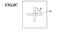
ここで、直径Dについて図8を参照して定義する。図8Aに示す吸着穴61aは円形状のため、開口の内部に収まる最大面積の円の直径D=吸着穴61aの直径である。吸着穴が円形状でない場合、たとえば図8Bに示す吸着穴61b、図8Cに示す吸着穴61cにあっては、その内側に一点鎖線で示す円は、開口の内部に収まる最大円であり、この円の直径をDと定義する。
なお、吸着穴の開口形状は、角形状があると角部に応力が集中するので、角部を丸めた形状にすることが好ましい。 As described above, in order to obtain the effect of preventing the generation of the suction hole pattern, the opening shape of the suction hole formed in the recording
Here, the diameter D is defined with reference to FIG. Since the
Note that the opening shape of the suction hole is preferably a shape in which the corner portion is rounded because stress concentrates on the corner portion if there is a corner shape.
支持層7の記録媒体保持層6と接する面に吸着溝71bが開口する場合、支持層7に設けられている吸引孔71の開口面積は、支持層7の記録媒体保持層6に接する面に開口する吸着溝71bの開口面積を指す。 Further, the
When the
記録媒体Mの厚さtと、吸着穴61の記録媒体に接する開口端の開口内に収まる最大円の直径Dをパラメータとして、吸着穴模様の発生の有無を調べた。
図11及び図12は、記録媒体保持層6が厚さ0.1mmのステンレスで、吸着穴61の配置はピッチ1.5Dの60°千鳥配置(開孔率40.3%)のときの吸着穴模様の発生の有無の評価結果である。図11の評価結果を出すに当たって記録媒体MとしてOKトップコート+(王子製紙)を使用した。図12の評価結果を出すに当たっては、記録媒体Mとしてnpi上質(日本製紙)を使用した。
図11及び図12に示されるように、薄い記録媒体でも吸着穴模様の発生を防ぐためには、直径Dが、D≦4tの関係を満足することで、吸着穴模様の発生を防ぐことができる。これは、記録媒体Mの吸着穴61の中心上の穴部から記録媒体保持層6との接触部までの距離を小さくすることで、穴部と接触部でインクに生じる温度ムラを低減することができるからであり、記録媒体が薄いほど記録媒体保持層6と記録媒体M上のインクとの距離が小さく温度ムラが生じやすいことから、記録媒体が薄いほど直径Dを小さくする必要がある。
記録媒体Mが厚くなるほど記録媒体保持層6と記録媒体M上のインクとの距離が大きく記録媒体Mによる断熱作用も大きくなるから、インクの温度ムラは緩和される。図12に示されるように、記録媒体Mの厚さが0.15mmを越える場合は、直径Dによらず吸着穴模様が発生しにくい。したがって、特に記録媒体Mの厚さが0.15mm以下であるインクジェット記録装置においては、本発明を効果的に適用することができる。 If the adsorption pressure is insufficient, the recording medium M may be displaced due to insufficient adsorption force, and if the adsorption pressure is excessive, the recording medium M may be deformed.
Using the thickness t of the recording medium M and the diameter D of the maximum circle that fits within the opening at the opening end of the
FIGS. 11 and 12 show the suction hole pattern when the recording
As shown in FIGS. 11 and 12, in order to prevent the generation of the suction hole pattern even in a thin recording medium, the generation of the suction hole pattern can be prevented when the diameter D satisfies the relationship of D ≦ 4t. . This is to reduce the temperature unevenness that occurs in the ink between the hole and the contact portion by reducing the distance from the hole on the center of the
The thicker the recording medium M, the greater the distance between the recording
吸引孔71としてφ1.0mmの孔がピッチ6mmの60°千鳥配置で開いている支持層7に、吸着穴61としてφ0.2mmの孔がピッチ0.3mmの60°千鳥配置で開いている厚さ0.1mmのステンレスの記録媒体保持層6を載せ、記録媒体Mとして100mm×297mmサイズの用紙を50kPaの負圧で吸着させたときの用紙の引き剥がし力をプルゲージで測定した。
この引き剥がし力の測定結果は180Nとなった。
記録媒体保持層6を排して支持層7に直接用紙を置いてその他は同じ条件で行ったところ、引き剥がし力は112Nと測定された。
以上の条件によれば、記録媒体保持層6を排した場合に対して記録媒体保持層6を挿入した場合は、記録媒体に対する開口率は減少する。
しかし、以上の測定結果のとおり吸着力は、記録媒体保持層6を挿入した方が増している。これは、図13に示すように、支持層7の吸引孔71と重なっていない吸着穴61も、記録媒体保持層6と支持層7との間のエアリークによって記録媒体Mを吸着する作用を発揮したためと考えられる。
したがって、吸引孔71に直接連通しない吸着穴61がある場合には、記録媒体保持層6とを支持層7と一体化せず、支持層7に記録媒体保持層6を積層してこの層間に吸引ポンプ3による吸引によってエアリークが可能に構成することが、高い吸着力を得るために有効である。 The adsorptive power was measured as follows.
Thickness in which holes of φ1.0 mm are opened in a 60 ° staggered arrangement with a pitch of 6 mm as suction holes 71 and holes of φ0.2 mm are opened in a 60 ° staggered arrangement with a pitch of 0.3 mm as suction holes 71. A stainless steel recording
The measurement result of the peeling force was 180N.
When the recording
According to the above conditions, when the recording
However, as shown in the above measurement results, the suction force increases when the recording
Therefore, when there is the
記録媒体保持層6の板厚が薄いと、吸着穴61の開口率が低くても剛性不足に陥る懸念がある。
また、記録媒体保持層6の板厚が薄いと記録媒体保持層6の熱容量が不十分で、インクジェット記録時の記録媒体保持層6の温度変化が大きくなって穴部と接触部の温度差が拡大し、吸引穴模様を発生させてしまう懸念がある。
記録媒体と記録媒体保持層の単位面積あたり熱容量の比率は1:4~1:10程度が好ましい。
記録媒体保持層6がSUS304のとき、厚さ0.4mmでは単位面積あたり熱容量は1862[J/(m2・K)]、厚さ0.05mmでは単位面積あたり熱容量は204[J/(m2・K)]である。記録媒体が0.06mmの上質紙のとき、単位面積あたり熱容量は102[J/(m2・K)]である。 The thickness of the recording
When the plate thickness of the recording
Further, if the plate thickness of the recording
The ratio of the heat capacity per unit area between the recording medium and the recording medium holding layer is preferably about 1: 4 to 1:10.
When the recording
アルミA5052の引張強さは230[N/mm2]、ステンレスSUS304の引張強さは520[N/mm2]である。
記録媒体保持層6は、記録媒体Mの吸着、排出を繰り返すため、繰り返し応力による機械的強度の低下に注意する必要がある。
ステンレスは繰り返し応力に対する疲労限度が存在するが、アルミは明確な疲労限度を持たず、繰り返し応力の回数を多くすると破断応力が低下することから、この観点からも記録媒体保持層6の材質はステンレスが好ましい。 The material of the recording
Aluminum A5052 has a tensile strength of 230 [N / mm 2 ], and stainless steel SUS304 has a tensile strength of 520 [N / mm 2 ].
Since the recording
Stainless steel has a fatigue limit for repeated stress, but aluminum does not have a clear fatigue limit. If the number of repeated stresses is increased, the breaking stress decreases. Therefore, from this point of view, the recording
インクとしてはエネルギー線(活性光線)が照射されることで硬化する活性光線硬化型インクを好適に適用できる。この活性光線硬化型インクは、ゲル化剤を1質量%以上10質量%未満含有しており、温度により可逆的にゾルゲル相転移することを特徴とする。ゾルゲル相転移とは、高温では流動性を持つ溶液状態であるが、ゲル化温度以下に冷却することで液全体がゲル化し流動性を失った状態に変化し、逆に低温で流動性を失った状態であるが、ゾル化温度以上に加熱することで、流動性を持つ液体状態に戻る現象を指す。 The ink that can be suitably applied to the ink will be described in detail below.
As the ink, an actinic ray curable ink that cures when irradiated with energy rays (active rays) can be suitably applied. This actinic ray curable ink contains 1% by mass or more and less than 10% by mass of a gelling agent, and is characterized by reversible sol-gel phase transition depending on temperature. The sol-gel phase transition is a solution state with fluidity at high temperatures, but when cooled below the gelation temperature, the entire liquid gels and changes to a state in which it loses fluidity, and conversely loses fluidity at low temperatures. This refers to a phenomenon that returns to a fluid state with fluidity when heated to a temperature equal to or higher than the solation temperature.
前記ゾルゲル相転移する活性光線硬化型インクは、高温では液体状態であるため、インクジェット記録ヘッドによる吐出が可能となる。この高温状態の活性光線硬化型インクを用いて記録すると、インク滴が記録媒体に着弾した後、温度差により自然冷却されることで速やかにインクが固化し、結果として隣り合うドット同士の合一を防いで画質劣化を防止できる。しかし、インク滴の固化力が強い場合には、ドット同士が孤立することで画像部に凹凸が生じ、極端な光沢低下や不自然なキラキラ感といった、光沢不均質感を招く場合があった。発明者らが鋭意検討した結果、インク滴の固化力、インクのゲル化温度、および記録媒体の温度を以下の範囲にすることで、インク滴同士の合一を防止して画質劣化を防ぐことができ、さらに最も自然な光沢感が得られることを見出した。すなわち、ゲル化剤を0.1質量%以上10質量%未満含有したインクの25℃における粘度が102mPa・s以上105mPa・s未満であるインクを用い、かつ該ゲル化剤によるインクのゲル化温度(Tgel)と記録媒体の表面温度(Ts)の差を5~15℃に制御して印字することで、インク液滴合一の防止による高画質と自然な光沢感の両立が可能となる。なおこの場合、媒体の調温範囲は42~48℃に相当する。 Here, gelation is an interaction such as a lamellar structure, a polymer network formed by non-covalent bonds or hydrogen bonds, a polymer network formed by a physical aggregation state, and an aggregate structure of fine particles. Refers to a structure in which substances lose their independent movement due to crystal interaction, etc., and indicate a solidified, semi-solidified, or thickened state with a sudden increase in viscosity or elasticity. . In addition, solification refers to a state in which the interaction formed by the gelation is eliminated and the liquid state is changed to a fluid state. In addition, the solation temperature is a temperature at which fluidity develops when the gelled ink is heated, and the gelation temperature is when the ink in the sol state is cooled. , Refers to the temperature at which the fluidity decreases due to gelation.
Since the sol-gel phase transition actinic ray curable ink is in a liquid state at a high temperature, it can be ejected by an ink jet recording head. When recording using this high-temperature actinic ray curable ink, after the ink droplets have landed on the recording medium, the ink is quickly cooled by natural cooling due to the temperature difference, and as a result, adjacent dots are coalesced. Can prevent image quality deterioration. However, when the solidification force of the ink droplet is strong, the dots are isolated, resulting in unevenness in the image area, which may lead to an uneven glossiness such as an extremely low glossiness or an unnatural sparkle. As a result of intensive studies by the inventors, by setting the solidification force of the ink droplets, the gelation temperature of the ink, and the temperature of the recording medium within the following ranges, it is possible to prevent the ink droplets from coalescing and to prevent image quality deterioration. And found that the most natural glossiness can be obtained. That is, an ink containing 0.1% by mass or more and less than 10% by mass of a gelling agent uses an ink having a viscosity at 25 ° C. of 10 2 mPa · s or more and less than 10 5 mPa · s, and the ink using the gelling agent By controlling the difference between the gelation temperature (Tgel) and the surface temperature (Ts) of the recording medium to 5 to 15 ° C, it is possible to achieve both high image quality and natural glossiness by preventing ink droplet coalescence. It becomes possible. In this case, the temperature control range of the medium corresponds to 42 to 48 ° C.
活性光線硬化型インクを用いて、インクのゲル化温度(Tgel)と記録媒体の表面温度(Ts)の差を5~15℃に調温することで、画質劣化がなく、文字などの細線の尖鋭性に優れ、自然な光沢感を持った画像を形成することが可能となるが、記録媒体の温度を5~10℃の範囲に調温することでより優れた画像を形成することが可能となる。 Note that the gloss homogeneity does not mean an absolute gloss value, for example, a 60-degree specular gloss value, but an unnatural glitter or unnecessary gloss caused by a microscopic gloss difference on the image. A state in which the gloss is not uniform in a part of the image, such as reduction or streaky gloss unevenness, is not observed, and the gloss of the entire surface of the image, particularly the solid print portion, is uniform.
Using actinic ray curable ink, the difference between the ink gel temperature (Tgel) and the surface temperature (Ts) of the recording medium is adjusted to 5 to 15 ° C. An image with excellent sharpness and natural glossiness can be formed, but a better image can be formed by adjusting the temperature of the recording medium in the range of 5 to 10 ° C. It becomes.
(ゲル化剤)
ゲル化とは、ラメラ構造、非共有結合や水素結合により形成される高分子網目、物理的な凝集状態によって形成される高分子網目、微粒子の凝集構造などの相互作用、析出した微結晶の相互作用などにより、物質が独立した運動を失って集合した構造を指しており、急激な粘度上昇や弾性増加を伴って固化した、または半固化した、または増粘した状態のことを指す。
一般に、ゲルには、加熱により流動性のある溶液(ゾルと呼ばれる場合もある)となり、冷却すると元のゲルに戻る熱可逆性ゲルと、一旦ゲル化してしまえば加熱しても、ふたたび溶液には戻らない熱不可逆性ゲルがある。オイルゲル化剤によって形成されるゲルは、ヘッド内の目詰まり防止の観点からは、熱可逆性ゲルであることが好ましい。
活性光線硬化型インクにおいては、インクのゲル化温度(相転移温度)が、40℃以上、100℃未満であることが好ましく、より好ましくは45℃以上、70℃以下である。夏場環境での気温を考慮すると、インクの相転移温度が40℃以上であれば、記録ヘッドからインク液滴を吐出する際に、印字環境温度に影響されることなく安定した出射性を得ることができ、また90℃未満であれば、インクジェット記録装置を過度の高温に加熱する必要がなく、インクジェット記録装置のヘッドやインク供給系の部材への負荷を低減することができる。 Hereinafter, the ink composition of the actinic ray curable ink applicable to the present invention will be sequentially described.
(Gelling agent)
Gelation refers to interactions such as lamellar structures, polymer networks formed by non-covalent bonds and hydrogen bonds, polymer networks formed by physical aggregation, and aggregated structures of fine particles. It refers to a structure in which substances lose their independent movement due to action or the like, and indicate a solidified, semi-solidified, or thickened state with a sudden increase in viscosity or elasticity.
In general, a gel becomes a fluid solution (sometimes called a sol) by heating, and a thermoreversible gel that returns to the original gel when cooled. There is a heat irreversible gel that does not return. The gel formed by the oil gelling agent is preferably a thermoreversible gel from the viewpoint of preventing clogging in the head.
In the actinic ray curable ink, the gelation temperature (phase transition temperature) of the ink is preferably 40 ° C. or higher and lower than 100 ° C., more preferably 45 ° C. or higher and 70 ° C. or lower. Considering the temperature in the summer environment, if the phase transition temperature of the ink is 40 ° C. or higher, stable ejection characteristics can be obtained without being affected by the printing environment temperature when ejecting ink droplets from the recording head. If the temperature is less than 90 ° C., it is not necessary to heat the inkjet recording apparatus to an excessively high temperature, and the load on the head of the inkjet recording apparatus and the members of the ink supply system can be reduced.
インクのゲル化温度の測定方法は、例えば、各種レオメータ(例えばコーンプレートを使用したストレス制御型レオメータ、PhysicaMCRシリーズ、Anton Paar社製)を用いて、ゾル状態にある高温のインクを低剪断速度で温度変化をさせながら得られる粘度曲線、動的粘弾性の温度変化を測定することで得られる粘弾性曲線から求めることができる。また、ガラス管に封じ込めた小鉄片を膨張計の中にいれ、温度変化に対してインク液中を自然落下しなくなった時点を相転移点とする方法(J.Polym.Sci.,21,57(1956))、インク上にアルミニウム製シリンダーを置き、ゲル温度を変化させた時に、アルミニウム製シリンダーが自然落下する温度を、ゲル化温度として測定する方法(日本レオロジー学会誌 Vol.17,86(1989))が挙げられる。また、簡便な方法としては、ヒートプレート上にゲル状の試験片を置き、ヒートプレートを加熱していき、試験片の形状が崩れる温度を測定し、これをゲル化温度として求めることができる。なお、使用するゲル化剤の種類、ゲル化剤の添加量、活性光線硬化型モノマーの種類を変えることで、インクのゲル化温度(相転移温度)は調整可能である。 The gelation temperature refers to the temperature at which the viscosity suddenly changes from a fluid solution state to a gel state. Gel transition temperature, gel dissolution temperature, phase transition temperature, sol-gel phase transition temperature, gel It is synonymous with a term called a conversion point.
The method for measuring the gelation temperature of the ink is, for example, using various rheometers (for example, a stress control type rheometer using a cone plate, Physica MCR series, manufactured by Anton Paar), and hot ink in a sol state at a low shear rate. It can be determined from a viscosity curve obtained while changing the temperature and a viscoelastic curve obtained by measuring the temperature change of dynamic viscoelasticity. In addition, a method in which a small iron piece sealed in a glass tube is placed in a dilatometer and a phase transition point is defined as a point at which the ink liquid does not naturally fall in response to a temperature change (J. Polym. Sci., 21, 57 (1956)), a method of measuring the temperature at which an aluminum cylinder naturally falls when an aluminum cylinder is placed on the ink and changing the gel temperature as a gelation temperature (Journal of Japanese Society of Rheology, Vol. 17, 86 ( 1989)). As a simple method, a gel-like test piece is placed on a heat plate, the heat plate is heated, the temperature at which the shape of the test piece collapses is measured, and this can be obtained as the gelation temperature. The gelation temperature (phase transition temperature) of the ink can be adjusted by changing the type of gelling agent used, the amount of gelling agent added, and the type of actinic ray curable monomer.
インクで用いられるゲル化剤は、高分子化合物であっても、低分子化合物であってもよいが、インクジェット射出性の観点から低分子化合物が好ましい。 In the ink applied to the present invention, the viscosity at 25 ° C. of the ink is preferably 10 2 mPa · s or more and less than 10 5 mPa · s, more preferably 10 3 mPa · s or more and less than 10 4 mPa · s. is there. If the ink viscosity is 10 2 mPa · s or more, deterioration of image quality due to dot coalescence can be prevented, and if it is less than 10 5 mPa · s, by controlling the surface temperature of the recording medium upon ink landing, A uniform gloss can be obtained by appropriate leveling. The viscosity of the ink can be appropriately adjusted by changing the type of gelling agent used, the amount of gelling agent added, and the type of actinic ray curable monomer. The ink viscosity was measured at a shear rate of 11.7 s −1 using a stress-controlled rheometer using a cone plate, Physica MCR series, manufactured by Anton Paar).
The gelling agent used in the ink may be a high molecular compound or a low molecular compound, but a low molecular compound is preferable from the viewpoint of ink jetting properties.
本発明で好ましく用いられる高分子化合物の具体例としては、ステアリン酸イヌリンなどの脂肪酸イヌリンや、パルミチン酸デキストリン、ミリスチン酸デキストリンなどの脂肪酸デキストリン(レオパールシリーズとして千葉製粉より入手可能)や、ベヘン酸エイコサン二酸グリセリル、ベヘン酸エイコサン二酸ポリグリセリル(ノムコートシリーズとして日清オイリオより入手可能)などが挙げられる。
本発明で好ましく用いられる低分子化合物の具体例としては、例えば特開2005-126507号や特開2005-255821号や特開2010-111790号の各公報に記載の低分子オイルゲル化剤や、N-ラウロイル-L-グルタミン酸ジブチルアミド、N-2エチルヘキサノイル-L-グルタミン酸ジブチルアミドなどのアミド化合物(味の素ファインテクノより入手可能)や、1,3:2,4-ビス-O-ベンジリデン-D-グルシトール(ゲルオールD 新日本理化より入手可能)などのジベンジリデンソルビトール類や、パラフィンワックス、マイクロクリスタリンワックス、ペトロラクタムなどの石油系ワックスや、キャンデリラワックス、カルナウバワックス、ライスワックス、木ロウ、ホホバ油、ホホバ固体ロウ、ホホバエステルなどの植物系ワックスや、ミツロウ、ラノリン、鯨ロウなどの動物系ワックスや、モンタンワックス、水素化ワックスなどの鉱物系ワックスや、硬化ヒマシ油または硬化ヒマシ油誘導体や、モンタンワックス誘導体,パラフィンワックス誘導体,マイクロクリスタリンワックス誘導体またはポリエチレンワックス誘導体などの変性ワックスや、ベヘン酸、アラキジン酸、ステアリン酸、パルミチン酸、ミリスチン酸、ラウリン酸、オレイン酸、エルカ酸などの高級脂肪酸や、ステアリルアルコ-ル、ベヘニルアルコ-ルなどの高級アルコ-ルや、12-ヒドロキシステアリン酸などのヒドロキシステアリン酸や、12-ヒドロキシステアリン酸誘導体や、ラウリン酸アミド、ステアリン酸アミド、ベヘン酸アミド、オレイン酸アミド、エルカ酸アミド、リシノ-ル酸アミド、12-ヒドロキシステアリン酸アミドなどの脂肪酸アミド(例えば、ニッカアマイドシリーズ 日本化成社製や、ITOWAXシリーズ 伊藤製油社製や、FATTYAMIDシリーズ 花王社製)や、N-ステアリルステアリン酸アミド、N-オレイルパルミチン酸アミドなどのN-置換脂肪酸アミドや、N,N´-エチレンビスステアリルアミド、N,N′-エチレンビス12-ヒドロキシステアリルアミド、N,N′-キシリレンビスステアリルアミドなどの特殊脂肪酸アミドや、ドデシルアミン、テトラデシルアミンまたはオクタデシルアミンなどの高級アミンや、ステアリルステアリン酸、オレイルパルミチン酸、グリセリン脂肪酸エステル、ソルビタン脂肪酸エステル、プロピレングリコ-ル脂肪酸エステル、エチレングリコ-ル脂肪酸エステル、ポリオキシエチレン脂肪酸エステルなどの脂肪酸エステル化合物(例えばEMALLEXシリーズ 日本エマルジョン社製や、リケマールシリーズ 理研ビタミン社製や、ポエムシリーズ 理研ビタミン社製)や、ショ糖ステアリン酸、ショ糖パルミチン酸などのショ糖脂肪酸エステル(例えばリョートーシュガーエステルシリーズ 三菱化学フーズ社製)や、ポリエチレンワックス、α-オレフィン無水マレイン酸共重合体ワックスなどの合成ワックスや、重合性ワックス(UNILINシリーズ Baker-Petrolite社製)や、ダイマー酸、ダイマージオール(PRIPORシリーズ CRODA社製)などが挙げられる。また、上記のゲル化剤は、単独で用いてもよいし、2種以上混合して用いてもよい。 Specific examples of the gelling agent that can be used in the ink according to the present invention are shown below, but the present invention is not limited only to these compounds.
Specific examples of the polymer compound preferably used in the present invention include fatty acid inulins such as inulin stearate, fatty acid dextrins such as dextrin palmitate and dextrin myristate (available from Chiba Flour as the Leopard series), eicosane behenate Examples include glyceryl diacid, eicosane behenate polyglyceryl (available from Nisshin Oilio as Nomcoat series), and the like.
Specific examples of the low molecular weight compound preferably used in the present invention include, for example, low molecular weight oil gelling agents described in JP-A-2005-126507, JP-A-2005-255821 and JP-A-2010-1111790, N -Lauroyl-L-glutamic acid dibutylamide, N-2 ethylhexanoyl-L-glutamic acid dibutylamide and other amide compounds (available from Ajinomoto Finetechno), 1,3: 2,4-bis-O-benzylidene-D -Dibenzylidene sorbitols such as Glucitol (available from Gelol D Shin Nippon Rika), petroleum waxes such as paraffin wax, microcrystalline wax, petrolactam, candelilla wax, carnauba wax, rice wax, wood wax, Jojoba oil, jojoba solid wax, ho Plant waxes such as hover esters, animal waxes such as beeswax, lanolin and whale wax, mineral waxes such as montan wax and hydrogenated wax, hardened castor oil or hardened castor oil derivatives, montan wax derivatives, paraffin wax Derivatives, modified waxes such as microcrystalline wax derivatives or polyethylene wax derivatives, higher fatty acids such as behenic acid, arachidic acid, stearic acid, palmitic acid, myristic acid, lauric acid, oleic acid, erucic acid, stearyl alcohol, Higher alcohols such as behenyl alcohol, hydroxystearic acid such as 12-hydroxystearic acid, 12-hydroxystearic acid derivatives, lauric acid amide, stearic acid amide, behenic acid amide, oleic acid acid Fatty acid amides such as nicotinic acid amide, ricinoleic acid amide, 12-hydroxystearic acid amide (for example, Nikka Amide series manufactured by Nippon Kasei Co., Ltd., ITOWAX series manufactured by Ito Oil Co., Ltd., FATTYAMID series manufactured by Kao Corporation) N-substituted fatty acid amides such as N-stearyl stearamide, N-oleyl palmitate, N, N'-ethylenebisstearylamide, N, N'-ethylenebis12-hydroxystearylamide, N, N'- Special fatty acid amides such as xylylene bisstearyl amide, higher amines such as dodecylamine, tetradecylamine or octadecylamine, stearyl stearic acid, oleyl palmitic acid, glycerin fatty acid ester, sorbitan fatty acid ester, propylene glycol Fatty acid ester compounds such as fatty acid esters, ethylene glycol fatty acid esters, polyoxyethylene fatty acid esters (for example, EMALLEX series manufactured by Nihon Emulsion, Rikumar series manufactured by RIKEN VITAMIN, POEM series manufactured by RIKEN VITAMIN), sucrose Synthetic waxes such as stearic acid and sucrose palmitic acid (eg, Ryoto Sugar Ester series manufactured by Mitsubishi Chemical Foods), polyethylene wax, α-olefin maleic anhydride copolymer wax, and polymerizable wax (UNILIN series Baker-Petrolite), dimer acid, dimer diol (PRIPOR series CRODA) and the like. Moreover, said gelling agent may be used independently and may be used in mixture of 2 or more types.
活性光線硬化型インクは、ゲル化剤、色材と共に、活性光線で硬化する活性光線硬化型組成物を含有する。
この活性光線硬化型組成物(以下、光重合性化合物ともいう)について説明する。
活性光線とは、例えば、電子線、紫外線、α線、γ線、エックス線等が挙げられるが、人体への危険性や、取り扱いが容易で、工業的にもその利用が普及している紫外線または電子線が好ましい。本発明では特に紫外線が好ましい。
本発明において、活性光線の照射により架橋または重合する光重合性化合物としては、特に制限なく用いることができるが、中でも光カチオン重合性化合物または光ラジカル重合性化合物を用いることが好ましい。 (Actinic ray curable composition)
The actinic ray curable ink contains an actinic ray curable composition that cures with actinic rays together with a gelling agent and a coloring material.
This actinic ray curable composition (hereinafter also referred to as a photopolymerizable compound) will be described.
Examples of actinic rays include electron beams, ultraviolet rays, α rays, γ rays, and X-rays. However, there are dangers to the human body, easy handling, and ultraviolet rays that are widely used industrially. An electron beam is preferred. In the present invention, ultraviolet rays are particularly preferable.
In the present invention, the photopolymerizable compound that is crosslinked or polymerized by irradiation with actinic rays can be used without particular limitation, but among them, a photocationic polymerizable compound or a photoradical polymerizable compound is preferably used.
光カチオン重合性モノマーとしては、各種公知のカチオン重合性のモノマーが使用できる。例えば、特開平6-9714号、特開2001-31892号、特開2001-40068号、特開2001-55507号、特開2001-310938号、特開2001-310937号、特開2001-220526号の各公報に例示されているエポキシ化合物、ビニルエーテル化合物、オキセタン化合物などが挙げられる。
本発明においては、インク硬化の際の記録媒体の収縮を抑える目的で、光重合性化合物として少なくとも1種のオキセタン化合物と、エポキシ化合物及びビニルエーテル化合物から選ばれる少なくとも1種の化合物とを含有することが好ましい。 (Cationically polymerizable compound)
As the photo cationic polymerizable monomer, various known cationic polymerizable monomers can be used. For example, JP-A-6-9714, JP-A-2001-31892, JP-A-2001-40068, JP-A-2001-55507, JP-A-2001-310938, JP-A-2001-310937, JP-A-2001-220526 Epoxy compounds, vinyl ether compounds, oxetane compounds and the like exemplified in each of the above publications.
In the present invention, for the purpose of suppressing shrinkage of the recording medium during ink curing, it contains at least one oxetane compound as a photopolymerizable compound and at least one compound selected from an epoxy compound and a vinyl ether compound. Is preferred.
脂環式エポキシドとしては、少なくとも1個のシクロヘキセンまたはシクロペンテン環等のシクロアルカン環を有する化合物を、過酸化水素、過酸等の適当な酸化剤でエポキシ化することにより得られる、シクロヘキセンオキサイドまたはシクロペンテンオキサイド含有化合物が好ましい。
脂肪族エポキシドの好ましいものとしては、脂肪族多価アルコールあるいはそのアルキレンオキサイド付加体のジまたはポリグリシジルエーテル等があり、その代表例としては、エチレングリコールのジグリシジルエーテル、プロピレングリコールのジグリシジルエーテルまたは1,6-ヘキサンジオールのジグリシジルエーテル等のアルキレングリコールのジグリシジルエーテル、グリセリンあるいはそのアルキレンオキサイド付加体のジまたはトリグリシジルエーテル等の多価アルコールのポリグリシジルエーテル、ポリエチレングリコールあるいはそのアルキレンオキサイド付加体のジグリシジルエーテル、ポリプロピレングリコールあるいはそのアルキレンオキサイド付加体のジグリシジルエーテル等のポリアルキレングリコールのジグリシジルエーテル等が挙げられる。ここでアルキレンオキサイドとしては、エチレンオキサイドおよびプロピレンオキサイド等が挙げられる。
これらのエポキシドのうち、速硬化性を考慮すると、芳香族エポキシドおよび脂環式エポキシドが好ましく、特に脂環式エポキシドが好ましい。本発明では、上記エポキシドの1種を単独で使用してもよいが、2種以上を適宜組み合わせて使用してもよい。
ビニルエーテル化合物としては、例えば、エチレングリコールジビニルエーテル、ジエチレングリコールジビニルエーテル、トリエチレングリコールジビニルエーテル、プロピレングリコールジビニルエーテル、ジプロピレングリコールジビニルエーテル、ブタンジオールジビニルエーテル、ヘキサンジオールジビニルエーテル、シクロヘキサンジメタノールジビニルエーテル、トリメチロールプロパントリビニルエーテル等のジ又はトリビニルエーテル化合物、エチルビニルエーテル、n-ブチルビニルエーテル、イソブチルビニルエーテル、オクタデシルビニルエーテル、シクロヘキシルビニルエーテル、ヒドロキシブチルビニルエーテル、2-エチルヘキシルビニルエーテル、シクロヘキサンジメタノールモノビニルエーテル、n-プロピルビニルエーテル、イソプロピルビニルエーテル、イソプロペニルエーテル-o-プロピレンカーボネート、ドデシルビニルエーテル、ジエチレングリコールモノビニルエーテル、オクタデシルビニルエーテル等のモノビニルエーテル化合物等が挙げられる。
これらのビニルエーテル化合物のうち、硬化性、密着性、表面硬度を考慮すると、ジ又はトリビニルエーテル化合物が好ましく、特にジビニルエーテル化合物が好ましい。本発明では、上記ビニルエーテル化合物の1種を単独で使用してもよいが、2種以上を適宜組み合わせて使用してもよい。 A preferable aromatic epoxide is a di- or polyglycidyl ether produced by the reaction of a polyhydric phenol having at least one aromatic nucleus or an alkylene oxide adduct thereof and epichlorohydrin, such as bisphenol A or an alkylene oxide thereof. Examples thereof include di- or polyglycidyl ethers of adducts, di- or polyglycidyl ethers of hydrogenated bisphenol A or its alkylene oxide adducts, and novolak-type epoxy resins. Here, examples of the alkylene oxide include ethylene oxide and propylene oxide.
As the alicyclic epoxide, cyclohexene oxide or cyclopentene obtained by epoxidizing a compound having at least one cycloalkane ring such as cyclohexene or cyclopentene ring with an appropriate oxidizing agent such as hydrogen peroxide or peracid. Oxide-containing compounds are preferred.
Preferred examples of the aliphatic epoxides include di- or polyglycidyl ethers of aliphatic polyhydric alcohols or alkylene oxide adducts thereof, and typical examples thereof include diglycidyl ether of ethylene glycol, diglycidyl ether of propylene glycol or Diglycidyl ether of alkylene glycol such as diglycidyl ether of 1,6-hexanediol, polyglycidyl ether of polyhydric alcohol such as di- or triglycidyl ether of glycerin or its alkylene oxide adduct, polyethylene glycol or its alkylene oxide adduct Of polyalkylene glycols such as diglycidyl ether, polypropylene glycol or diglycidyl ether of its alkylene oxide adduct Glycidyl ether, and the like. Here, examples of the alkylene oxide include ethylene oxide and propylene oxide.
Among these epoxides, in view of fast curability, aromatic epoxides and alicyclic epoxides are preferable, and alicyclic epoxides are particularly preferable. In the present invention, one of the above epoxides may be used alone, or two or more may be used in appropriate combination.
Examples of the vinyl ether compound include ethylene glycol divinyl ether, diethylene glycol divinyl ether, triethylene glycol divinyl ether, propylene glycol divinyl ether, dipropylene glycol divinyl ether, butanediol divinyl ether, hexanediol divinyl ether, cyclohexanedimethanol divinyl ether, Di- or trivinyl ether compounds such as methylolpropane trivinyl ether, ethyl vinyl ether, n-butyl vinyl ether, isobutyl vinyl ether, octadecyl vinyl ether, cyclohexyl vinyl ether, hydroxybutyl vinyl ether, 2-ethylhexyl vinyl ether, cyclohexane dimethanol monovinyl ether, n-propyl Pills vinyl ether, isopropyl vinyl ether, isopropenyl ether -o- propylene carbonate, dodecyl vinyl ether, diethylene glycol monovinyl ether, and octadecyl vinyl ether.
Among these vinyl ether compounds, in consideration of curability, adhesion, and surface hardness, di- or trivinyl ether compounds are preferable, and divinyl ether compounds are particularly preferable. In the present invention, one of the above vinyl ether compounds may be used alone, or two or more thereof may be used in appropriate combination.
本発明で用いることのできるオキセタン化合物において、オキセタン環を5個以上有する化合物を使用すると、インク組成物の粘度が高くなるため、取扱いが困難になること、またインク組成物のガラス転移温度が高くなるため、得られる硬化物の粘着性が十分でなくなることがある。本発明で使用するオキセタン環を有する化合物は、オキセタン環を1~4個有する化合物が好ましい。
本発明で好ましく用いることのできるオキセタン環を有する化合物としては、特開2005-255821号公報の段落番号(0089)に記載されている、一般式(1)で表される化合物、同じく同号公報の段落番号(0092)に記載されている、一般式(2)、段落番号(0107)の一般式(7)、段落番号(0109)の一般式(8)、段落番号(0166)の一般式(9)等で表される化合物を挙げることができる。
具体的には、同号公報の段落番号(0104)~(0119)に記載されている例示化合物1~6及び段落番号(0121)に記載されている化合物を挙げることができる。 The oxetane compound referred to in the present invention is a compound having an oxetane ring, and any known oxetane compound as described in JP-A Nos. 2001-220526 and 2001-310937 can be used.
In the oxetane compound that can be used in the present invention, if a compound having 5 or more oxetane rings is used, the viscosity of the ink composition becomes high, which makes handling difficult, and the glass transition temperature of the ink composition is high. Therefore, the tackiness of the obtained cured product may not be sufficient. The compound having an oxetane ring used in the present invention is preferably a compound having 1 to 4 oxetane rings.
Examples of the compound having an oxetane ring that can be preferably used in the present invention include compounds represented by general formula (1) described in paragraph No. (0089) of JP-A No. 2005-255821 and the same publication. The general formula (2), the general formula (7) of the paragraph number (0107), the general formula (8) of the paragraph number (0109), and the general formula of the paragraph number (0166) described in the paragraph number (0092) of The compound represented by (9) etc. can be mentioned.
Specific examples thereof include the exemplified
次いで、ラジカル重合性化合物について説明する。
光ラジカル重合性モノマーとしては、各種公知のラジカル重合性のモノマーが使用できる。例えば、特開平7-159983号、特公平7-31399号、特開平8-224982号、特開平10-863号の各公報に記載されている光重合性組成物を用いた光硬化型材料と、カチオン重合系の光硬化性樹脂が知られており、最近では可視光以上の長波長域に増感された光カチオン重合系の光硬化性樹脂も例えば、特開平6-43633号公報、特開平8-324137公報等に公開されている。
ラジカル重合性化合物は、ラジカル重合可能なエチレン性不飽和結合を有する化合物であり、分子中にラジカル重合可能なエチレン性不飽和結合を少なくとも1つ有する化合物であればどの様なものでもよく、モノマー、オリゴマー、ポリマー等の化学形態をもつものが含まれる。ラジカル重合性化合物は1種のみ用いてもよく、また目的とする特性を向上するために任意の比率で2種以上を併用してもよい。
ラジカル重合可能なエチレン性不飽和結合を有する化合物の例としては、アクリル酸、メタクリル酸、イタコン酸、クロトン酸、イソクロトン酸、マレイン酸等の不飽和カルボン酸及びそれらの塩、エステル、ウレタン、アミドや無水物、アクリロニトリル、スチレン、更に種々の不飽和ポリエステル、不飽和ポリエーテル、不飽和ポリアミド、不飽和ウレタン等のラジカル重合性化合物が挙げられる。
ラジカル重合性化合物としては、公知のあらゆる(メタ)アクリレートモノマー及び/またはオリゴマーを用いることができる。ここでいう「および/または」は、モノマーであっても、オリゴマーであっても良く、更に両方を含んでも良いことを意味する。また、以下に述べる事項に関しても同様である。 (Radically polymerizable compound)
Next, the radical polymerizable compound will be described.
Various known radically polymerizable monomers can be used as the photoradical polymerizable monomer. For example, photocurable materials using photopolymerizable compositions described in JP-A-7-159983, JP-B-7-31399, JP-A-8-224982, and JP-A-10-863 and Cationic polymerization photocurable resins are known. Recently, photocationic polymerization photocurable resins sensitized to a long wavelength region longer than visible light are disclosed in, for example, JP-A-6-43633. It is disclosed in the Kaihei 8-324137 publication.
The radical polymerizable compound is a compound having an ethylenically unsaturated bond capable of radical polymerization, and may be any compound as long as it has at least one ethylenically unsaturated bond capable of radical polymerization in the molecule. , Oligomers, polymers and the like having a chemical form. Only one kind of radically polymerizable compound may be used, or two or more kinds thereof may be used in combination at an arbitrary ratio in order to improve desired properties.
Examples of compounds having an ethylenically unsaturated bond capable of radical polymerization include unsaturated carboxylic acids such as acrylic acid, methacrylic acid, itaconic acid, crotonic acid, isocrotonic acid, maleic acid and their salts, esters, urethanes, amides. And radically polymerizable compounds such as various anhydrides, acrylonitrile, styrene, various unsaturated polyesters, unsaturated polyethers, unsaturated polyamides, and unsaturated urethanes.
Any known (meth) acrylate monomer and / or oligomer can be used as the radical polymerizable compound. The term “and / or” as used herein means that it may be a monomer or an oligomer, and may further include both. The same applies to the items described below.
更に、これらの中でも、ステアリルアクリレート、ラウリルアクリレート、イソステアリルアクリレート、エトキシジエチレングリコールアクリレート、イソボルニルアクリレート、テトラエチレングリコールジアクリレート、グリセリンプロポキシトリアクリレート、カウプロラクトン変性トリメチロールプロパントリアクリレート、カプロラクタム変性ジペンタエリスリトールヘキサアクリレートが特に好ましい。 Among the above monomers, isoamyl acrylate, stearyl acrylate, lauryl acrylate, octyl acrylate, decyl acrylate, isomyristyl acrylate are particularly preferred from the viewpoints of sensitization, skin irritation, eye irritation, mutagenicity, toxicity, etc. , Isostearyl acrylate, ethoxydiethylene glycol acrylate, methoxypolyethylene glycol acrylate, methoxypropylene glycol acrylate, isobornyl acrylate, lactone-modified flexible acrylate, tetraethylene glycol diacrylate, polyethylene glycol diacrylate, polypropylene glycol diacrylate, dipentaerythritol Hexaacrylate, ditrimethylolpropane tetraacrylate, glycerin Po carboxymethyl triacrylate, caprolactone modified trimethylolpropane triacrylate, pentaerythritol tetraacrylate, caprolactam modified dipentaerythritol hexaacrylate preferred.
Furthermore, among these, stearyl acrylate, lauryl acrylate, isostearyl acrylate, ethoxydiethylene glycol acrylate, isobornyl acrylate, tetraethylene glycol diacrylate, glycerin propoxy triacrylate, cowprolactone-modified trimethylolpropane triacrylate, caprolactam-modified dipenta Erythritol hexaacrylate is particularly preferred.
また本発明においては、重合性化合物として各種ビニルエーテル化合物とマレイミド化合物を併用して用いることも可能である。マレイミド化合物としては、例えば、N-メチルマレイミド、N-プロピルマレイミド、N-ヘキシルマレイミド、N-ラウリルマレイミド、N-シクロヘキシルマレイミド、N-フェニルマレイミド、N,N′-メチレンビスマレイミド、ポリプロピレングリコール-ビス(3-マレイミドプロピル)エーテル、テトラエチレングリコール-ビス(3-マレイミドプロピル)エーテル、ビス(2-マレイミドエチル)カーボネート、N,N′-(4,4′-ジフェニルメタン)ビスマレイミド、N,N′-2,4-トリレンビスマレイミド、あるいは、また特開平11-124403号公報に開示されているマレイミドカルボン酸と種々のポリオール類とのエステル化合物である多官能マレイミド化合物などが挙げられるが、この限りではない。
上記カチオン重合性化合物及びラジカル重合性化合物の添加量は好ましくは1~97質量%であり、より好ましくは30~95質量%である。 In the present invention, a vinyl ether monomer and / or oligomer and a (meth) acrylate monomer and / or oligomer may be used in combination as the polymerizable compound. Examples of the vinyl ether monomer include ethylene glycol divinyl ether, diethylene glycol divinyl ether, triethylene glycol divinyl ether, propylene glycol divinyl ether, dipropylene glycol divinyl ether, butanediol divinyl ether, hexanediol divinyl ether, cyclohexanedimethanol divinyl ether, Di- or trivinyl ether compounds such as methylolpropane trivinyl ether, ethyl vinyl ether, n-butyl vinyl ether, isobutyl vinyl ether, octadecyl vinyl ether, cyclohexyl vinyl ether, hydroxybutyl vinyl ether, 2-ethylhexyl vinyl ether, cyclohexane dimethanol monovinyl ether, n- B pills vinyl ether, isopropyl vinyl ether, isopropenyl ether -o- propylene carbonate, dodecyl vinyl ether, diethylene glycol monovinyl ether, and octadecyl vinyl ether. When a vinyl ether oligomer is used, a bifunctional vinyl ether compound having a molecular weight of 300 to 1000 and having 2 to 3 ester groups in the molecule is preferable. For example, compounds available as VEctomer series of ALDRICH, VEctomer 4010, VEctomer 4020, VEctomer 4040 , VEctomer 4060, VEctomer 5015 and the like are preferable, but not limited thereto.
In the present invention, various vinyl ether compounds and maleimide compounds can be used in combination as the polymerizable compound. Examples of maleimide compounds include N-methylmaleimide, N-propylmaleimide, N-hexylmaleimide, N-laurylmaleimide, N-cyclohexylmaleimide, N-phenylmaleimide, N, N'-methylenebismaleimide, polypropylene glycol-bis (3-maleimidopropyl) ether, tetraethylene glycol-bis (3-maleimidopropyl) ether, bis (2-maleimidoethyl) carbonate, N, N '-(4,4'-diphenylmethane) bismaleimide, N, N' -2,4-tolylene bismaleimide or a polyfunctional maleimide compound which is an ester compound of maleimide carboxylic acid and various polyols disclosed in JP-A-11-124403. As far as There.
The addition amount of the cationic polymerizable compound and the radical polymerizable compound is preferably 1 to 97% by mass, more preferably 30 to 95% by mass.
次いで、本発明に適用できるインクについて、上記項目を除いた各構成要素について説明する。
(色材)
インクを構成する色材としては、染料あるいは顔料を制限なく用いることができるが、インク成分に対し良好な分散安定性を有し、かつ耐候性に優れた顔料を用いることが好ましい。顔料としては、特に限定されるわけではないが、本発明には、例えば、カラーインデックスに記載される下記の番号の有機又は無機顔料が使用できる。
赤或いはマゼンタ顔料としては、Pigment Red 3、5、19、22、31、38、43、48:1、48:2、48:3、48:4、48:5、49:1、53:1、57:1、57:2、58:4、63:1、81、81:1、81:2、81:3、81:4、88、104、108、112、122、123、144、146、149、166、168、169、170、177、178、179、184、185、208、216、226、257、Pigment Violet 3、19、23、29、30、37、50、88、Pigment Orange 13、16、20、36、
青又はシアン顔料としては、Pigment Blue 1、15、15:1、15:2、15:3、15:4、15:6、16、17-1、22、27、28、29、36、60、
緑顔料としては、Pigment Green 7、26、36、50、
黄顔料としては、Pigment Yellow 1、3、12、13、14、17、34、35、37、55、74、81、83、93、94,95、97、108、109、110、137、138、139、153、154、155、157、166、167、168、180、185、193、 (Each component of ink)
Next, regarding the ink applicable to the present invention, each component excluding the above items will be described.
(Coloring material)
As the color material constituting the ink, a dye or a pigment can be used without limitation, but it is preferable to use a pigment having good dispersion stability with respect to the ink component and excellent weather resistance. Although it does not necessarily limit as a pigment, For example, the organic or inorganic pigment of the following number described in a color index can be used for this invention.
Examples of red or magenta pigments include
Examples of blue or cyan pigments include
Examples of green pigments include
As the yellow pigment,
具体的に商品名を示すと、例えば、クロモファインイエロー2080、5900、5930、AF-1300、2700L、クロモファインオレンジ3700L、6730、クロモファインスカーレット6750、クロモファインマゼンタ6880、6886、6891N、6790、6887、クロモファインバイオレットRE、クロモファインレッド6820、6830、クロモファインブルーHS-3、5187、5108、5197、5085N、SR-5020、5026、5050、4920、4927、4937、4824、4933GN-EP、4940、4973、5205、5208、5214、5221、5000P、クロモファイングリーン2GN、2GO、2G-550D、5310、5370、6830、クロモファインブラックA-1103、セイカファストエロー10GH、A-3、2035、2054、2200、2270、2300、2400(B)、2500、2600、ZAY-260、2700(B)、2770、セイカファストレッド8040、C405(F)、CA120、LR-116、1531B、8060R、1547、ZAW-262、1537B、GY、4R-4016、3820、3891、ZA-215、セイカファストカーミン6B1476T-7、1483LT、3840、3870、セイカファストボルドー10B-430、セイカライトローズR40、セイカライトバイオレットB800、7805、セイカファストマルーン460N、セイカファストオレンジ900、2900、セイカライトブルーC718、A612、シアニンブルー4933M、4933GN-EP、4940、4973(大日精化工業製)、KET Yellow 401、402、403、404、405、406、416、424、KET Orange 501、KET Red 301、302、303、304、305、306、307、308、309、310、336、337、338、346、KET Blue 101、102、103、104、105、106、111、118、124、KET Green 201(大日本インキ化学製)、Colortex Yellow 301、314、315、316、P-624、314、U10GN、U3GN、UNN、UA-414、U263、Finecol Yellow T-13、T-05、Pigment Yellow1705、Colortex Orange 202、Colortex Red101、103、115、116、D3B、P-625、102、H-1024、105C、UFN、UCN、UBN、U3BN、URN、UGN、UG276、U456、U457、105C、USN、Colortex Maroon601、Colortex BrownB610N、Colortex Violet600、Pigment Red 122、Colortex Blue516、517、518、519、A818、P-908、510、Colortex Green402、403、Colortex Black 702、U905(山陽色素製)、Lionol Yellow1405G、Lionol Blue FG7330、FG7350、FG7400G、FG7405G、ES、ESP-S(東洋インキ製)、Toner Magenta E02、Permanent RubinF6B、Toner Yellow HG、Permanent Yellow GG-02、Hostapeam BlueB2G(ヘキストインダストリ製)、Novoperm P-HG、Hostaperm Pink E、Hostaperm Blue B2G(クラリアント製)、カーボンブラック#2600、#2400、#2350、#2200、#1000、#990、#980、#970、#960、#950、#850、MCF88、#750、#650、MA600、MA7、MA8、MA11、MA100、MA100R、MA77、#52、#50、#47、#45、#45L、#40、#33、#32、#30、#25、#20、#10、#5、#44、CF9(三菱化学製)などが挙げられる。 As the black pigment,
Specific product names include, for example, chromo fine yellow 2080, 5900, 5930, AF-1300, 2700L, chromo fine orange 3700L, 6730, chromo fine scarlet 6750, chromo fine magenta 6880, 6886, 6891N, 6790, 6887. , Chromofine Violet RE, Chromofine Red 6820, 6830, Chromofine Blue HS-3, 5187, 5108, 5197, 5085N, SR-5020, 5026, 5050, 4920, 4927, 4937, 4824, 4933GN-EP, 4940, 4973, 5205, 5208, 5214, 5221, 5000P, Chromofine Green 2GN, 2GO, 2G-550D, 5310, 5370, 6830, Black Fine Black A-1103, Seika Fast Yellow 10GH, A-3, 2035, 2054, 2200, 2270, 2300, 2400 (B), 2500, 2600, ZAY-260, 2700 (B), 2770, Seika Fast Red 8040, C405 (F), CA120, LR-116, 1531B, 8060R, 1547, ZAW-262, 1537B, GY, 4R-4016, 3820, 3891, ZA-215, Seika Fast Carmine 6B1476T-7, 1483LT, 3840, 3870, Seika Fast Bordeaux 10B-430, Seika Light Rose R40, Seika Light Violet B800, 7805, Seika Fast Maroon 460N, Seika Fast Orange 900, 2900, Seika Light Blue C7 8, A612, cyanine blue 4933M, 4933GN-EP, 4940, 4973 (manufactured by Dainichi Seikagaku), KET Yellow 401, 402, 403, 404, 405, 406, 416, 424, KET Orange 501, KET Red 301, 302 , 303, 304, 305, 306, 307, 308, 309, 310, 336, 337, 338, 346, KET Blue 101, 102, 103, 104, 105, 106, 111, 118, 124, KET Green 201 (large (Manufactured by Nippon Ink Chemical), Colortex Yellow 301, 314, 315, 316, P-624, 314, U10GN, U3GN, UNN, UA-414, U263, Finecol Yellow T-13, T-05, Pigment Yellow 1705, Colortex Orange 202, Colortex Red 101, 103, 115, 116, D3B, P-625, 102, H-1024, 105C, UFN, UCN, UBN, U3BN, URN, UGN, UG276, U456, U457, 105C, USN , Colortex Maron601, Colortex BrownB610N, Colortex violet600, Pigment Red 122, Colortex Blue516, 517, 518, 519, A818, P-908, 510, Color5, 402, 403, Col70, Col90, Col90, Col90 Lionol Blue FG7330 FG7350, FG7400G, FG7405G, ES, ESP-S (manufactured by Toyo Ink), Toner Magenta E02, Permanent RubinF6B, Toner Yellow HG, Permanent Yellow MG-02, Hostape BlueBH E, Hostaperm Blue B2G (manufactured by Clariant), carbon black # 2600, # 2400, # 2350, # 2200, # 1000, # 990, # 980, # 970, # 960, # 950, # 850, MCF88, # 750, # 650, MA600, MA7, MA8, MA11, MA100, MA100R, MA77, # 52, # 50, # 47, # 4 , # 45L, # 40, # 33, # 32, # 30, # 25, # 20, # 10, # 5, # 44, CF9 (manufactured by Mitsubishi Chemical) and the like.
また、顔料の分散を行う際に、分散剤を添加することも可能である。分散剤としては、高分子分散剤を用いることが好ましく、高分子分散剤としては、例えば、Avecia社のSolsperseシリーズや、味の素ファインテクノ社のPBシリーズが挙げられる。更には、下記のものが挙げられる。
顔料分散剤としては、水酸基含有カルボン酸エステル、長鎖ポリアミノアマイドと高分子量酸エステルの塩、高分子量ポリカルボン酸の塩、長鎖ポリアミノアマイドと極性酸エステルの塩、高分子量不飽和酸エステル、高分子共重合物、変性ポリウレタン、変性ポリアクリレート、ポリエーテルエステル型アニオン系活性剤、ナフタレンスルホン酸ホルマリン縮合物塩、芳香族スルホン酸ホルマリン縮合物塩、ポリオキシエチレンアルキル燐酸エステル、ポリオキシエチレンノニルフェニルエーテル、ステアリルアミンアセテート、顔料誘導体等を挙げることができる。 For the dispersion of the pigment, for example, a ball mill, sand mill, attritor, roll mill, agitator, Henschel mixer, colloid mill, ultrasonic homogenizer, pearl mill, wet jet mill, paint shaker, or the like can be used.
In addition, a dispersing agent can be added when dispersing the pigment. As the dispersant, a polymer dispersant is preferably used. Examples of the polymer dispersant include Avecia's Solsperse series and Ajinomoto Fine-Techno's PB series. Furthermore, the following are mentioned.
Examples of the pigment dispersant include a hydroxyl group-containing carboxylic acid ester, a salt of a long chain polyaminoamide and a high molecular weight acid ester, a salt of a high molecular weight polycarboxylic acid, a salt of a long chain polyaminoamide and a polar acid ester, a high molecular weight unsaturated acid ester, Polymer copolymer, modified polyurethane, modified polyacrylate, polyether ester type anionic activator, naphthalene sulfonic acid formalin condensate salt, aromatic sulfonic acid formalin condensate salt, polyoxyethylene alkyl phosphate ester, polyoxyethylene nonyl Examples thereof include phenyl ether, stearylamine acetate, and pigment derivatives.
また、Efka CHEMICALS社製「エフカ44、46、47、48、49、54、63、64、65、66、71、701、764、766」、「エフカポリマー100(変性ポリアクリレート)、150(脂肪族系変性ポリマー)、400、401、402、403、450、451、452、453(変性ポリアクリレート)、745(銅フタロシアニン系)」;共栄化学社製「フローレンTG-710(ウレタンオリゴマー)」、「フローノンSH-290、SP-1000」、「ポリフローNo.50E、No.300(アクリル系共重合物)」;楠本化成社製「ディスパロンKS-860、873SN、874(高分子分散剤)、#2150(脂肪族多価カルボン酸)、#7004(ポリエーテルエステル型)」等が挙げられる。
更には、花王社製「デモールRN、N(ナフタレンスルホン酸ホルマリン縮合物ナトリウム塩)、MS、C、SN-B(芳香族スルホン酸ホルマリン縮合物ナトリウム塩)、EP」、「ホモゲノールL-18(ポリカルボン酸型高分子)」、「エマルゲン920、930、931、935、950、985(ポリオキシエチレンノニルフェニルエーテル)」、「アセタミン24(ココナッツアミンアセテート)、86(ステアリルアミンアセテート)」;ゼネカ社製「ソルスパーズ5000(フタロシアニンアンモニウム塩系)、13240、13940(ポリエステルアミン系)、17000(脂肪酸アミン系)、24000、32000」;日光ケミカル社製「ニッコールT106(ポリオキシエチレンソルビタンモノオレート)、MYS-IEX(ポリオキシエチレンモノステアレート)、Hexagline4-0(ヘキサグリセリルテトラオレート)」等が挙げられる。 Specific examples include “Anti-Terra-U (polyaminoamide phosphate)”, “Anti-Terra-203 / 204 (high molecular weight polycarboxylate)”, “Disperbyk-101 (polyaminoamide phosphate) manufactured by BYK Chemie. And acid ester), 107 (hydroxyl group-containing carboxylic acid ester), 110 (copolymer containing an acid group), 130 (polyamide), 161, 162, 163, 164, 165, 166, 170 (polymer copolymer) ”,“ 400 ”,“ Bykumen ”(high molecular weight unsaturated acid ester),“ BYK-P104, P105 (high molecular weight unsaturated acid polycarboxylic acid) ”,“ P104S, 240S (high molecular weight unsaturated acid polycarboxylic acid and Silicone) ”,“ Lactimon (long-chain amine, unsaturated polycarboxylic acid and silico) ) ”.
Also, “Efka CHEMICALS” “
Furthermore, “Demol RN, N (Naphthalenesulfonic acid formalin condensate sodium salt), MS, C, SN-B (aromatic sulfonic acid formalin condensate sodium salt), EP”, “Homogenol L-18 (made by Kao Co., Ltd.) Polycarboxylic acid type polymer) "," Emulgen 920, 930, 931, 935, 950, 985 (polyoxyethylene nonylphenyl ether) "," acetamine 24 (coconut amine acetate), 86 (stearyl amine acetate) ";"Solspers 5000 (phthalocyanine ammonium salt type), 13240, 13940 (polyesteramine type), 17000 (fatty acid amine type), 24000, 32000"; Nikko Chemical's "Nikkor T106 (polyoxyethylene sorbitan monooleate), MY" -IEX (polyoxyethylene monostearate), Hexagline4-0 (hexaglyceryl ruthenate Huwei rate) ", and the like.
顔料の分散は、顔料粒子の平均粒径を0.08~0.5μmとすることが好ましく、最大粒径は0.3~10μm、好ましくは0.3~3μmとなるよう、顔料、分散剤、分散媒体の選定、分散条件、ろ過条件を適宜設定する。この粒径管理によって、記録ヘッドのノズルの詰まりを抑制し、インクの保存安定性、インク透明性および硬化感度を維持することができる。 These pigment dispersants are preferably contained in the ink in the range of 0.1 to 20% by mass. Moreover, it is also possible to use a synergist according to various pigments as a dispersion aid. These dispersants and dispersion aids are preferably added in an amount of 1 to 50 parts by mass with respect to 100 parts by mass of the pigment. The dispersion medium is used using a solvent or a polymerizable compound. However, since the ink is reacted and cured after printing, it is preferably solventless. If the solvent remains in the cured image, the solvent resistance deteriorates and the VOC of the remaining solvent arises. Therefore, it is preferable in view of dispersibility that the dispersion medium is not a solvent but a polymerizable compound, and among them, a monomer having the lowest viscosity is selected.
The pigment is preferably dispersed so that the average particle diameter of the pigment particles is 0.08 to 0.5 μm, and the maximum particle diameter is 0.3 to 10 μm, preferably 0.3 to 3 μm. The selection of the dispersion medium, the dispersion conditions, and the filtration conditions are appropriately set. By controlling the particle size, clogging of the nozzles of the recording head can be suppressed, and ink storage stability, ink transparency, and curing sensitivity can be maintained.
MS Magenta VP、MS Magenta HM-1450、MS Magenta HSo-147(以上、三井東圧社製)、AIZENSOT Red-1、AIZEN SOT Red-2、AIZEN SOTRed-3、AIZEN SOT Pink-1、SPIRON Red GEH SPECIAL(以上、保土谷化学社製)、RESOLIN Red FB 200%、MACROLEX Red Violet R、MACROLEX ROT5B(以上、バイエルジャパン社製)、KAYASET Red B、KAYASET Red 130、KAYASET Red 802(以上、日本化薬社製)、PHLOXIN、ROSE BENGAL、ACID Red(以上、ダイワ化成社製)、HSR-31、DIARESIN Red K(以上、三菱化成社製)、Oil Red(BASFジャパン社製)。 (Magenta dye)
MS Magenta VP, MS Magenta HM-1450, MS Magenta HSo-147 (manufactured by Mitsui Toatsu Co., Ltd.), AIZENSOT Red-1, AIZEN SOT Red-2, AIZEN SOTRed-3, AIZEN SOT Pink-1, SPERON Red GE SPECIAL (above, manufactured by Hodogaya Chemical Co., Ltd.), RESOLIN Red FB 200%, MACROLEX Red Violet R, MACROLEX ROT5B (above, manufactured by Bayer Japan), KAYASET Red B, KAYASET Red 130, KAYASET Red Japan 802 ), PHLOXIN, ROSE BENGAL, ACID Red (above, made by Daiwa Kasei Co., Ltd.), HSR-31, DIARESIN Red K (below) , Manufactured by Mitsubishi Kasei Co., Ltd.), Oil Red (manufactured by BASF Japan Co., Ltd.).
MS Cyan HM-1238、MS Cyan HSo-16、Cyan HSo-144、MS Cyan VPG(以上、三井東圧社製)、AIZEN SOT Blue-4(保土谷化学社製)、RESOLIN BR.Blue BGLN 200%、MACROLEX Blue RR、CERES Blue GN、SIRIUS SUPRATURQ.Blue Z-BGL、SIRIUS SUPRA TURQ.Blue FB-LL 330%(以上、バイエルジャパン社製)、KAYASET Blue FR、KAYASET Blue N、KAYASET Blue 814、Turq.Blue GL-5 200、Light Blue BGL-5 200(以上、日本化薬社製)、DAIWA Blue 7000、Oleosol Fast Blue GL(以上、ダイワ化成社製)、DIARESIN Blue P(三菱化成社製)、SUDAN Blue 670、NEOPEN Blue 808、ZAPON Blue 806(以上、BASFジャパン社製)。 (Cyan dye)
MS Cyan HM-1238, MS Cyan HSo-16, Cyan HSo-144, MS Cyan VPG (manufactured by Mitsui Toatsu), AIZEN SOT Blue-4 (manufactured by Hodogaya Chemical Co., Ltd.), RESOLIN BR. Blue BGLN 200%, MACROLEX Blue RR, CERES Blue GN, SIRIUS SUPRATURQ. Blue Z-BGL, SIRIUS SUTRA TURQ. Blue FB-LL 330% (manufactured by Bayer Japan Co., Ltd.), KAYASET Blue FR, KAYASET Blue N, KAYASET Blue 814, Turq. Blue GL-5 200, Light Blue BGL-5 200 (manufactured by Nippon Kayaku Co., Ltd.), DAIWA Blue 7000, Olesol Fast Blue GL (manufactured by Daiwa Kasei Co., Ltd.), DIARESIN Blue P (manufactured by Mitsubishi Kasei), SUDAN Blue 670, NEOPEN Blue 808, ZAPON Blue 806 (above, manufactured by BASF Japan).
MS Yellow HSm-41、Yellow KX-7、Yellow EX-27(三井東圧)、AIZEN SOT Yellow-1、AIZEN SOT YelloW-3、AIZEN SOT Yellow-6(以上、保土谷化学社製)、MACROLEX Yellow 6G、MACROLEX FLUOR.Yellow 10GN(以上、バイエルジャパン社製)、KAYASET Yellow SF-G、KAYASET Yellow2G、KAYASET Yellow A-G、KAYASET Yellow E-G(以上、日本化薬社製)、DAIWA Yellow 330HB(ダイワ化成社製)、HSY-68(三菱化成社製)、SUDAN Yellow 146、NEOPEN Yellow 075(以上、BASFジャパン社製)。 (Yellow dye)
MS Yellow HSm-41, Yellow KX-7, Yellow EX-27 (Mitsui Toatsu), AIZEN SOT Yellow-1, AIZEN SOT YellowW-3, AIZEN SOT Yellow-6 (above, manufactured by Hodogaya Chemical Co., Ltd.), MACROLEX Yellow 6G, MACROLEX FLUOR. Yellow 10GN (above, manufactured by Bayer Japan), KAYASET Yellow SF-G, KAYASET Yellow 2G, KAYASET Yellow AG, KAYASET Yellow EG (above, manufactured by Nippon Kayaku Co., Ltd.), DAIWA YELLOW 330H HSY-68 (manufactured by Mitsubishi Kasei Co., Ltd.), SUDAN Yellow 146, NEOPEN Yellow 075 (above, manufactured by BASF Japan).
MS Black VPC(三井東圧社製)、AIZEN SOT Black-1、AIZEN SOT Black-5(以上、保土谷化学社製)、RESORIN Black GSN 200%、RESOLIN BlackBS(以上、バイエルジャパン社製)、KAYASET Black A-N(日本化薬社製)、DAIWA Black MSC(ダイワ化成社製)、HSB-202(三菱化成社製)、NEPTUNE Black X60、NEOPEN Black X58(以上、BASFジャパン社製)等である。 (Black dye)
MS Black VPC (Mitsui Toatsu Co., Ltd.), AIZEN SOT Black-1, AIZEN SOT Black-5 (above, Hodogaya Chemical Co., Ltd.), RESORIN Black GSN 200%, RESOLIN Black BS (above, Bayer Japan, Inc.), KAYASET Black A-N (manufactured by Nippon Kayaku Co., Ltd.), DAIWA Black MSC (manufactured by Daiwa Kasei Co., Ltd.), HSB-202 (manufactured by Mitsubishi Kasei Co., Ltd.), NEPTUNE Black X60, NEOPEN Black X58 (manufactured by BASF Japan) .
活性光線として紫外線等を用いる場合には、少なくとも1種の光重合開始剤を含有することが好ましい。だたし、活性光線として電子線を用いる場合には、多くの場合、光重合開始剤を必要としない。
光重合開始剤は、分子内結合開裂型と分子内水素引き抜き型の2種に大別できる。
分子内結合開裂型の光重合開始剤としては、例えば、ジエトキシアセトフェノン、2-ヒドロキシ-2-メチル-1-フェニルプロパン-1-オン、ベンジルジメチルケタール、1-(4-イソプロピルフェニル)-2-ヒドロキシ-2-メチルプロパン-1-オン、4-(2-ヒドロキシエトキシ)フェニル-(2-ヒドロキシ-2-プロピル)ケトン、1-ヒドロキシシクロヘキシル-フェニルケトン、2-メチル-2-モルホリノ(4-チオメチルフェニル)プロパン-1-オン、2-ベンジル-2-ジメチルアミノ-1-(4-モルホリノフェニル)-ブタノンの如きアセトフェノン系;ベンゾイン、ベンゾインメチルエーテル、ベンゾインイソプロピルエーテルの如きベンゾイン類;2,4,6-トリメチルベンゾインジフェニルホスフィンオキシドの如きアシルホスフィンオキシド系;ベンジル、メチルフェニルグリオキシエステル、などが挙げられる。
一方、分子内水素引き抜き型の光重合開始剤としては、例えば、ベンゾフェノン、o-ベンゾイル安息香酸メチル-4-フェニルベンゾフェノン、4,4′-ジクロロベンゾフェノン、ヒドロキシベンゾフェノン、4-ベンゾイル-4′-メチル-ジフェニルサルファイド、アクリル化ベンゾフェノン、3,3′,4,4′-テトラ(t-ブチルペルオキシカルボニル)ベンゾフェノン、3,3′-ジメチル-4-メトキシベンゾフェノンの如きベンゾフェノン系;2-イソプロピルチオキサントン、2,4-ジメチルチオキサントン、2,4-ジエチルチオキサントン、2,4-ジクロロチオキサントンの如きチオキサントン系;ミヒラ-ケトン、4,4′-ジエチルアミノベンゾフェノンの如きアミノベンゾフェノン系;10-ブチル-2-クロロアクリドン、2-エチルアンスラキノン、9,10-フェナンスレンキノン、カンファーキノン、などが挙げられる。 (Photopolymerization initiator)
When ultraviolet rays or the like are used as the actinic rays, it is preferable to contain at least one photopolymerization initiator. However, in the case where an electron beam is used as the actinic ray, a photopolymerization initiator is not required in many cases.
Photopolymerization initiators can be broadly classified into two types: intramolecular bond cleavage type and intramolecular hydrogen abstraction type.
Examples of the intramolecular bond cleavage type photopolymerization initiator include diethoxyacetophenone, 2-hydroxy-2-methyl-1-phenylpropan-1-one, benzyldimethyl ketal, and 1- (4-isopropylphenyl) -2. -Hydroxy-2-methylpropan-1-one, 4- (2-hydroxyethoxy) phenyl- (2-hydroxy-2-propyl) ketone, 1-hydroxycyclohexyl-phenylketone, 2-methyl-2-morpholino (4 Acetophenones such as -thiomethylphenyl) propan-1-one, 2-benzyl-2-dimethylamino-1- (4-morpholinophenyl) -butanone; benzoins such as benzoin, benzoin methyl ether, benzoin isopropyl ether; 2 , 4,6-Trimethylbenzoindiphenyl Scan fins oxides such acylphosphine oxide of benzil, methyl phenylglyoxylate esters.
On the other hand, examples of the intramolecular hydrogen abstraction type photopolymerization initiator include benzophenone, methyl 4-phenylbenzophenone, 4,4'-dichlorobenzophenone, hydroxybenzophenone, 4-benzoyl-4'-methyl, o-benzoylbenzoate. Benzophenones such as diphenyl sulfide, acrylated benzophenone, 3,3 ′, 4,4′-tetra (t-butylperoxycarbonyl) benzophenone, 3,3′-dimethyl-4-methoxybenzophenone; 2-isopropylthioxanthone, 2 Thioxanthone series such as 1,4-dimethylthioxanthone, 2,4-diethylthioxanthone, 2,4-dichlorothioxanthone; Michler-ketone, aminobenzophenone series such as 4,4'-diethylaminobenzophenone; 10-butyl- - chloro acridone, 2-ethyl anthraquinone, 9,10-phenanthrenequinone, camphorquinone, and the like.
また、ラジカル重合開始剤としては、特公昭59-1281号、特公昭61-9621号、及び特開昭60-60104号等の各公報記載のトリアジン誘導体、特開昭59-1504号及び特開昭61-243807号等の各公報に記載の有機過酸化物、特公昭43-23684号、特公昭44-6413号、特公昭44-6413号及び特公昭47-1604号等の各公報並びに米国特許第3,567,453号明細書に記載のジアゾニウム化合物、米国特許第2,848,328号、同第2,852,379号及び同2,940,853号各明細書に記載の有機アジド化合物、特公昭36-22062号、特公昭37-13109号、特公昭38-18015号、特公昭45-9610号等の各公報に記載のオルト-キノンジアジド類、特公昭55-39162号、特開昭59-14023号等の各公報及び「マクロモレキュルス(Macromolecules)、第10巻、第1307頁(1977年)に記載の各種オニウム化合物、特開昭59-142205号公報に記載のアゾ化合物、特開平1-54440号公報、ヨーロッパ特許第109,851号、ヨーロッパ特許第126,712号等の各明細書、「ジャーナル・オブ・イメージング・サイエンス」(J.Imag.Sci.)」、第30巻、第174頁(1986年)に記載の金属アレン錯体、特許第2711491号及び特許第2803454号明細書に記載の(オキソ)スルホニウム有機ホウ素錯体、特開昭61-151197号公報に記載のチタノセン類、「コーディネーション・ケミストリー・レビュー(Coordination Chemistry Review)」、第84巻、第85~第277頁(1988年)及び特開平2-182701号公報に記載のルテニウム等の遷移金属を含有する遷移金属錯体、特開平3-209477号公報に記載の2,4,5-トリアリールイミダゾール二量体、四臭化炭素や特開昭59-107344号公報記載の有機ハロゲン化合物等が挙げられる。これらの重合開始剤はラジカル重合可能なエチレン不飽和結合を有する化合物100質量部に対して0.01から10質量部の範囲で含有されるのが好ましい。
また、光重合開始剤として、光酸発生剤も用いることができる。 When the photopolymerization initiator is used, the blending amount is preferably in the range of 0.01 to 10% by mass of the actinic ray curable composition.
Examples of the radical polymerization initiator include triazine derivatives described in JP-B-59-1281, JP-B-61-9621, JP-A-60-60104, JP-A-59-1504, and JP-A-59-1504. Organic peroxides described in JP-A-61-243807, JP-B-43-23684, JP-B-44-6413, JP-B-44-6413, JP-B-47-1604, etc., and the United States Diazonium compounds described in Japanese Patent No. 3,567,453, organic azides described in US Pat. Nos. 2,848,328, 2,852,379 and 2,940,853 Compounds, ortho-quinonediazides described in JP-B 36-22062, JP-B 37-13109, JP-B 38-18015, JP-B 45-9610, and the like; Various onium compounds described in JP-A-55-39162, JP-A-59-14023 and the like, and “Macromolecules, Vol. 10, page 1307 (1977); No. 142205, JP-A-1-54440, European Patent No. 109,851, European Patent No. 126,712, etc., “Journal of Imaging Science” (J. Imag. Sci.), Vol. 30, page 174 (1986), (oxo) sulfonium organoboron complexes described in Japanese Patent Nos. 2711491 and 2803454, 61-151197, titanocenes, “Coordination Chemistry Levi” (Coordination Chemistry Review), Vol. 84, 85-277 (1988) and JP-A-2-182701, transition metal complexes containing transition metals such as ruthenium, JP-A-3-209477 And 2,4,5-triarylimidazole dimer, carbon tetrabromide, and organic halogen compounds described in JP-A-59-107344. These polymerization initiators are preferably contained in the range of 0.01 to 10 parts by mass with respect to 100 parts by mass of the compound having an ethylenically unsaturated bond capable of radical polymerization.
A photoacid generator can also be used as a photopolymerization initiator.
第1に、ジアゾニウム、アンモニウム、ヨードニウム、スルホニウム、ホスホニウムなどの芳香族オニウム化合物のB(C6F5)4 -、PF6 -、AsF6 -、SbF6 -、CF3SO3 -塩を挙げることができる。
本発明で用いることのできるオニウム化合物の具体的な例としては、特開2005-255821号公報の段落番号(0132)に記載されている化合物を挙げることができる。
第2に挙げられる、スルホン酸を発生するスルホン化物の具体的な化合物としては、特開2005-255821号公報の段落番号(0136)に記載されている化合物を挙げることができる。
第2に、ハロゲン化水素を光発生するハロゲン化物も用いることができ、その具体的な化合物としては、特開2005-255821号公報の段落番号(0138)に記載されている化合物を挙げることができる。
第3に、特開2005-255821号公報の段落番号(0140)に記載されている鉄アレン錯体を挙げることができる。 As the photoacid generator, for example, a chemically amplified photoresist or a compound used for photocationic polymerization is used (edited by Organic Electronics Materials Research Group, “Organic Materials for Imaging”, Bunshin Publishing (1993), 187. See page 192). Examples of compounds suitable for the present invention are listed below.
First, B (C 6 F 5 ) 4 − , PF 6 − , AsF 6 − , SbF 6 − , and CF 3 SO 3 — salts of aromatic onium compounds such as diazonium, ammonium, iodonium, sulfonium, and phosphonium are listed. be able to.
Specific examples of the onium compound that can be used in the present invention include compounds described in paragraph No. (0132) of JP-A No. 2005-255821.
Specific examples of the sulfonated compound that generates sulfonic acid include compounds described in paragraph No. (0136) of JP-A No. 2005-255821.
Secondly, halides that generate hydrogen halide can also be used, and specific examples thereof include compounds described in paragraph No. (0138) of JP-A No. 2005-255821. it can.
Thirdly, an iron allene complex described in paragraph No. (0140) of JP-A-2005-255821 can be mentioned.
活性光線硬化型インクには、上記説明した以外に様々な添加剤を用いることができる。例えば、界面活性剤、レベリング添加剤、マット剤、膜物性を調整するためのポリエステル系樹脂、ポリウレタン系樹脂、ビニル系樹脂、アクリル系樹脂、ゴム系樹脂、ワックス類を添加することができる。また、保存安定性を改良する目的で公知のあらゆる塩基性化合物を用いることができるが、代表的なものとして、塩基性アルカリ金属化合物、塩基性アルカリ土類金属化合物、アミンなどの塩基性有機化合物などが挙げられる。 (Other additives)
In addition to the above description, various additives can be used for the actinic ray curable ink. For example, surfactants, leveling additives, matting agents, polyester resins for adjusting film properties, polyurethane resins, vinyl resins, acrylic resins, rubber resins, and waxes can be added. In addition, any known basic compound can be used for the purpose of improving storage stability. Typical examples include basic organic compounds such as basic alkali metal compounds, basic alkaline earth metal compounds, and amines. Etc.
なお、以下のインク組成物において用いられる顔料分散体は、ソルスパーズ32000(ルーブリゾール社製)5部と、HD-N(1,6-ヘキサンジオールジメタクリレート:新中村化学社製)80部とをステンレスビーカーに入れ加熱撹拌溶解し、これを室温まで冷却した後、カーボンブラック(#56:三菱化学社製)15部を加えて、0.5mmのジルコニアビーズとともにガラスビンに入れ密栓し、ペイントシェーカーにて10時間分散処理してから、ジルコニアビーズを除去したものである。 Hereinafter, specific examples of the ink used in the present embodiment will be listed.
In addition, the pigment dispersion used in the following ink composition contains 5 parts of Solspers 32000 (manufactured by Lubrizol) and 80 parts of HD-N (1,6-hexanediol dimethacrylate: Shin-Nakamura Chemical Co., Ltd.). After stirring and dissolving in a stainless steel beaker and cooling it to room temperature, add 15 parts of carbon black (# 56: manufactured by Mitsubishi Chemical Corporation), seal it in a glass bottle with 0.5 mm zirconia beads, and put it in a paint shaker. Then, after 10 hours of dispersion treatment, zirconia beads were removed.

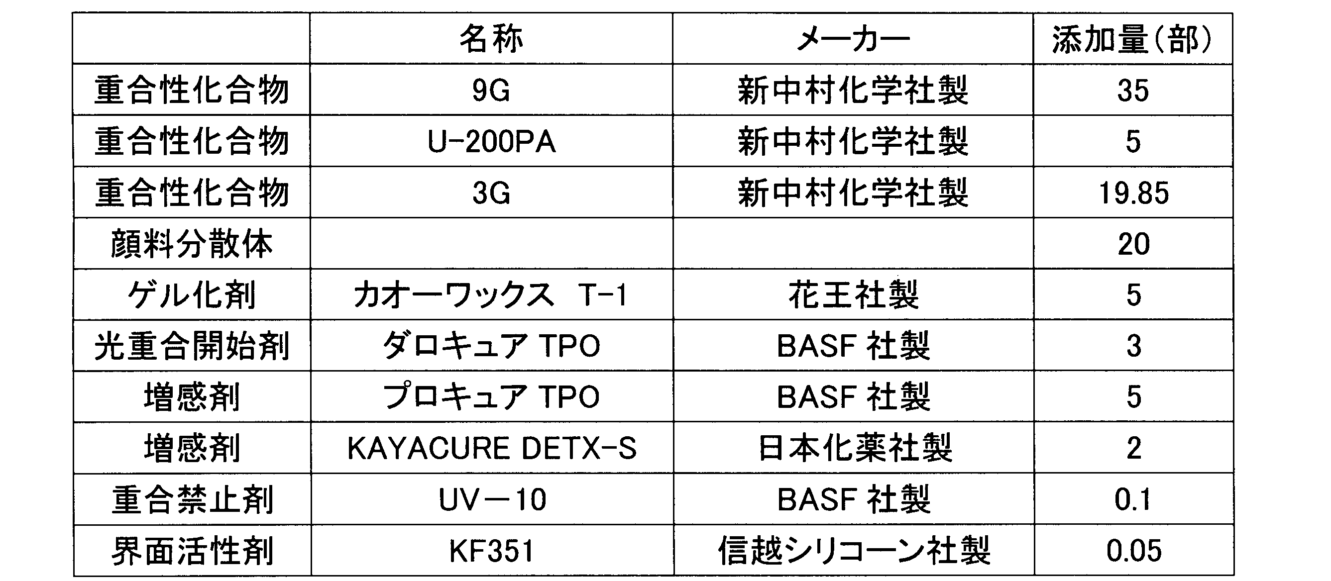
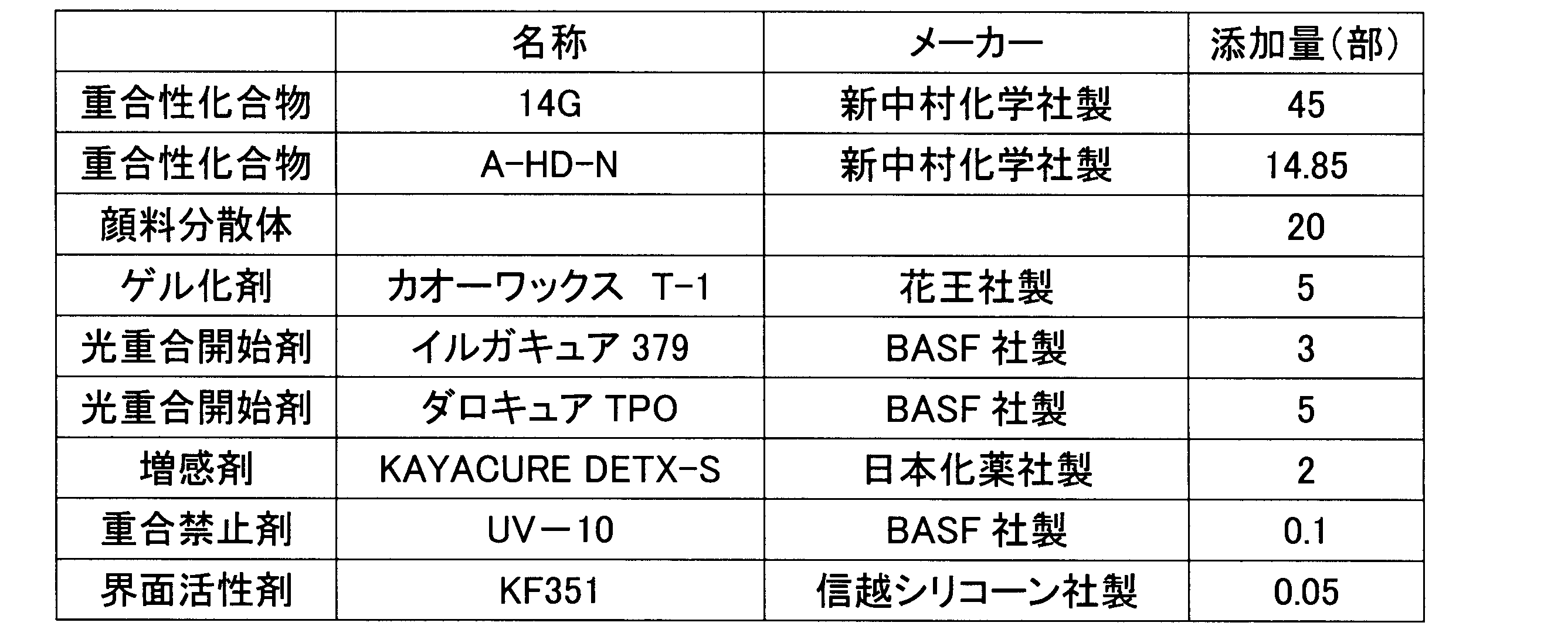


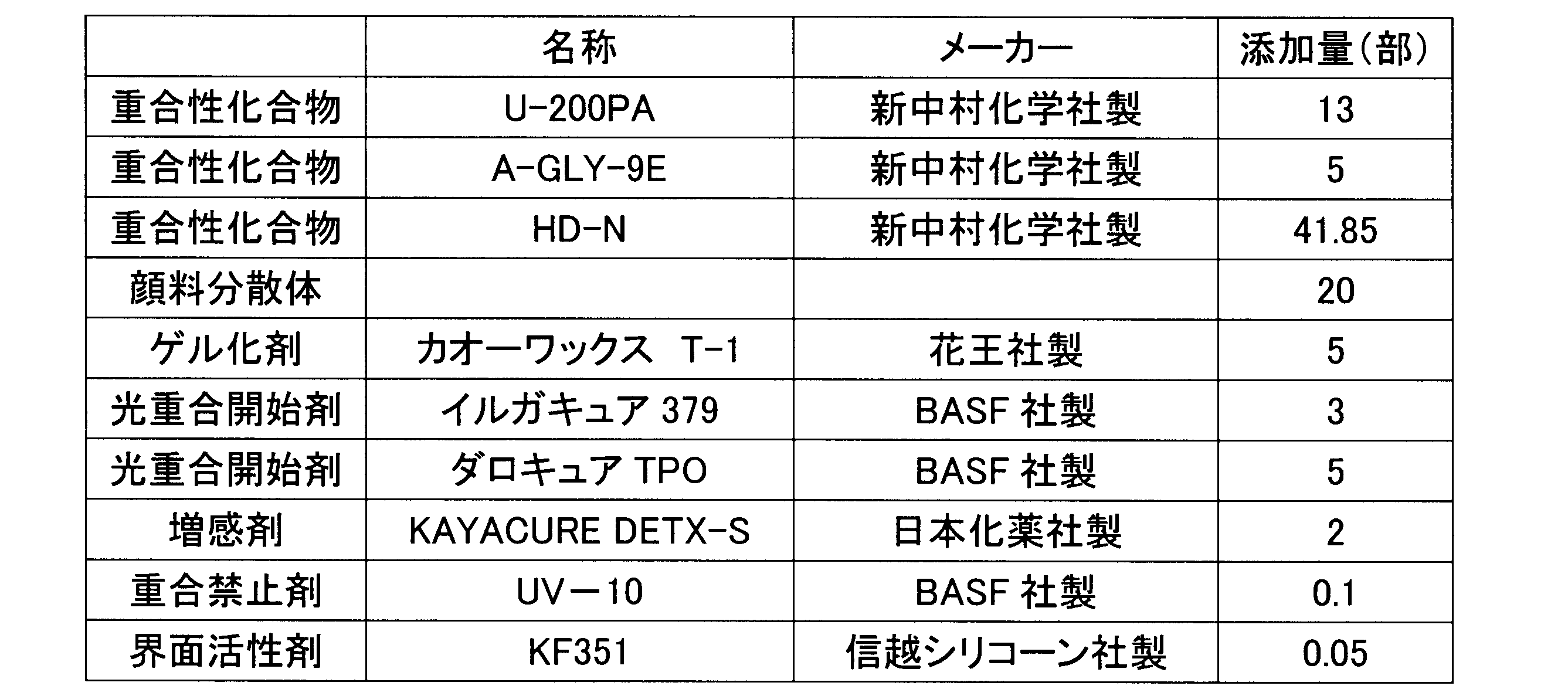
2 記録媒体固定手段
3 吸引ポンプ
41 インクジェット記録ヘッド
6 記録媒体保持層
61 吸着穴
7 支持層
71 吸引孔
M 記録媒体 DESCRIPTION OF
Claims (7)
- 温度によってゲル状又は固体状と、液状とに相変化するインクを用いたインクジェット記録装置であって、
記録媒体に接する吸着穴を介したエア吸引により当該記録媒体を吸着固定する記録媒体固定手段と、
前記エア吸引のための負圧を発生するための負圧発生手段と、
前記記録媒体に対して液状の前記インクを吐出するインクジェット記録ヘッドと、
を備え、
前記記録媒体固定手段は、
前記吸着穴が形成され、前記インクがゲル状又は固体状となる温度に保持される記録媒体保持層と、
前記記録媒体保持層を支持する少なくとも1つの層から構成され、前記吸着穴に連通する吸引孔が形成された支持層と、を有し、
前記吸着穴の前記記録媒体に接する開口端の開口面積が、前記吸引孔の前記記録媒体保持層に接する開口端の開口面積より小さいことを特徴とするインクジェット記録装置。 An ink jet recording apparatus using an ink that changes in phase from a gel or a solid to a liquid according to temperature,
A recording medium fixing means for adsorbing and fixing the recording medium by air suction through an adsorption hole in contact with the recording medium;
Negative pressure generating means for generating a negative pressure for air suction;
An ink jet recording head for discharging the liquid ink to the recording medium;
With
The recording medium fixing means includes
A recording medium holding layer in which the suction hole is formed and the ink is held at a temperature at which the ink becomes a gel or solid;
A support layer that includes at least one layer that supports the recording medium holding layer, and has a suction hole that communicates with the suction hole.
An ink jet recording apparatus, wherein an opening area of an opening end of the suction hole in contact with the recording medium is smaller than an opening area of an opening end of the suction hole in contact with the recording medium holding layer. - 前記記録媒体の厚さtに対し、前記吸着穴の前記記録媒体に接する開口端の開口内に収まる最大円の直径Dが、D≦4tの関係を満足することを特徴とする請求項1に記載のインクジェット記録装置。 The diameter D of the maximum circle that can be accommodated in the opening at the opening end of the suction hole in contact with the recording medium with respect to the thickness t of the recording medium satisfies a relationship of D ≦ 4t. The ink jet recording apparatus described.
- 前記記録媒体に接する前記記録媒体保持層の表面領域を占める前記吸着穴の開口面積で表される開口率が、5%以上75%以下であることを特徴とする請求項1又は請求項2に記載のインクジェット記録装置。 3. The aperture ratio represented by an opening area of the suction hole that occupies the surface area of the recording medium holding layer in contact with the recording medium is 5% or more and 75% or less. The ink jet recording apparatus described.
- 前記記録媒体保持層の厚さが0.05mm以上0.4mm以下であることを特徴とする請求項1から請求項3のうちいずれか一に記載のインクジェット記録装置。 The inkjet recording apparatus according to any one of claims 1 to 3, wherein a thickness of the recording medium holding layer is 0.05 mm or more and 0.4 mm or less.
- 前記記録媒体保持層の材質がステンレスであることを特徴とする請求項1から請求項4のうちいずれか一に記載のインクジェット記録装置。 The ink jet recording apparatus according to claim 1, wherein a material of the recording medium holding layer is stainless steel.
- 前記記録媒体固定手段を所定の温度に加熱する加熱手段を備えることを特徴とする請求項1から請求項5のうちいずれか一に記載のインクジェット記録装置。 The inkjet recording apparatus according to claim 1, further comprising a heating unit that heats the recording medium fixing unit to a predetermined temperature.
- 前記記録媒体の厚さが0.15mm以下であることを特徴とする請求項1から請求項6のうちいずれか一に記載のインクジェット記録装置。 The inkjet recording apparatus according to claim 1, wherein the recording medium has a thickness of 0.15 mm or less.
Priority Applications (4)
| Application Number | Priority Date | Filing Date | Title |
|---|---|---|---|
| US14/113,621 US20140049590A1 (en) | 2011-04-27 | 2012-04-25 | Inkjet recording device |
| CN201280019857.7A CN103502015B (en) | 2011-04-27 | 2012-04-25 | Ink-jet recording apparatus |
| EP12777114.5A EP2703173A4 (en) | 2011-04-27 | 2012-04-25 | Inkjet recording device |
| JP2013512386A JP5954317B2 (en) | 2011-04-27 | 2012-04-25 | Inkjet recording device |
Applications Claiming Priority (2)
| Application Number | Priority Date | Filing Date | Title |
|---|---|---|---|
| JP2011099562 | 2011-04-27 | ||
| JP2011-099562 | 2011-04-27 |
Publications (1)
| Publication Number | Publication Date |
|---|---|
| WO2012147760A1 true WO2012147760A1 (en) | 2012-11-01 |
Family
ID=47072278
Family Applications (1)
| Application Number | Title | Priority Date | Filing Date |
|---|---|---|---|
| PCT/JP2012/061024 WO2012147760A1 (en) | 2011-04-27 | 2012-04-25 | Inkjet recording device |
Country Status (5)
| Country | Link |
|---|---|
| US (1) | US20140049590A1 (en) |
| EP (1) | EP2703173A4 (en) |
| JP (1) | JP5954317B2 (en) |
| CN (1) | CN103502015B (en) |
| WO (1) | WO2012147760A1 (en) |
Cited By (4)
| Publication number | Priority date | Publication date | Assignee | Title |
|---|---|---|---|---|
| WO2015015483A1 (en) * | 2013-07-28 | 2015-02-05 | Hewlett-Packard Industrial Printing Ltd. | Media support |
| JP2018176496A (en) * | 2017-04-07 | 2018-11-15 | セイコーエプソン株式会社 | Liquid discharge device |
| US20220088949A1 (en) * | 2018-12-20 | 2022-03-24 | Kateeva, Inc. | Inkjet printer with temperature controlled substrate support |
| JP7457346B2 (en) | 2019-11-27 | 2024-03-28 | アジア・ラゲージ株式会社 | inkjet printing equipment |
Families Citing this family (6)
| Publication number | Priority date | Publication date | Assignee | Title |
|---|---|---|---|---|
| US20140208970A1 (en) * | 2011-08-22 | 2014-07-31 | Windmoeller & Hoelscher Kg | Machine and method for printing material webs |
| WO2013026792A1 (en) * | 2011-08-22 | 2013-02-28 | Windmöller & Hölscher Kg | Machine and method for printing webs of material |
| JP6277624B2 (en) * | 2013-08-05 | 2018-02-14 | セイコーエプソン株式会社 | Recording device |
| JP6672825B2 (en) * | 2016-01-20 | 2020-03-25 | セイコーエプソン株式会社 | Printing equipment |
| FR3051718A1 (en) * | 2016-05-27 | 2017-12-01 | Mgi Digital Tech | DEVICE AND METHOD FOR MAINTAINING / TRANSPORTING SUBSTRATES IN A PRINTING MACHINE |
| WO2023211452A1 (en) * | 2022-04-28 | 2023-11-02 | Hewlett-Packard Development Company, L.P. | Printing on a garment |
Citations (49)
| Publication number | Priority date | Publication date | Assignee | Title |
|---|---|---|---|---|
| US2848328A (en) | 1954-06-16 | 1958-08-19 | Eastman Kodak Co | Light sensitive diazo compound and binder composition |
| US2852379A (en) | 1955-05-04 | 1958-09-16 | Eastman Kodak Co | Azide resin photolithographic composition |
| US2940853A (en) | 1958-08-21 | 1960-06-14 | Eastman Kodak Co | Azide sensitized resin photographic resist |
| JPS3622062B1 (en) | 1960-01-14 | 1961-11-15 | ||
| JPS3713109B1 (en) | 1960-01-14 | 1962-09-06 | ||
| JPS3818015B1 (en) | 1960-11-11 | 1963-09-12 | ||
| JPS4323684B1 (en) | 1965-04-01 | 1968-10-12 | ||
| JPS446413B1 (en) | 1965-06-28 | 1969-03-19 | ||
| JPS459610B1 (en) | 1965-07-19 | 1970-04-07 | ||
| US3567453A (en) | 1967-12-26 | 1971-03-02 | Eastman Kodak Co | Light sensitive compositions for photoresists and lithography |
| JPS471604B1 (en) | 1968-12-06 | 1972-01-17 | ||
| JPS5539162B2 (en) | 1975-05-02 | 1980-10-08 | ||
| JPS591504A (en) | 1982-06-26 | 1984-01-06 | Nippon Oil & Fats Co Ltd | Photopolymerization initiator composition |
| JPS591281B2 (en) | 1971-09-03 | 1984-01-11 | ミネソタ マイニング アンド マニュファクチュアリング コンパニ− | Hikarijiyugokaishizai |
| JPS5914023A (en) | 1982-07-15 | 1984-01-24 | Chugoku Denki Seizo Kk | Method for controlling suppressing device of flicker |
| EP0109851A2 (en) | 1982-11-22 | 1984-05-30 | Minnesota Mining And Manufacturing Company | Energy polymerizable compositions containing organometallic initiators |
| JPS59107344A (en) | 1982-12-13 | 1984-06-21 | Hitachi Chem Co Ltd | Photosensitive resin composition |
| JPS59142205A (en) | 1983-02-02 | 1984-08-15 | Nippon Oil & Fats Co Ltd | Highly sensitive photoinitiator composition |
| EP0126712A1 (en) | 1983-05-18 | 1984-11-28 | Ciba-Geigy Ag | Curable composition and use thereof |
| JPS6060104A (en) | 1983-09-12 | 1985-04-06 | Fuji Photo Film Co Ltd | Photopolymerizable composition |
| JPS619621B2 (en) | 1978-05-18 | 1986-03-25 | Fuji Photo Film Co Ltd | |
| JPS61151197A (en) | 1984-12-20 | 1986-07-09 | チバ‐ガイギー アーゲー | Titanocenes and radiation-curable composition containing same |
| JPS61243807A (en) | 1985-04-23 | 1986-10-30 | Nippon Oil & Fats Co Ltd | Photopolymerization initiator |
| JPS6454440A (en) | 1987-08-24 | 1989-03-01 | Toyo Boseki | Photopolymerizable composition |
| JPH02182701A (en) | 1988-11-08 | 1990-07-17 | Mead Corp:The | Photosensitive composition containing transition metal coodination complex cation and borate anion, and photosensitive material made by using it |
| JPH0371850A (en) | 1989-08-11 | 1991-03-27 | Fuji Xerox Co Ltd | Print recording |
| JPH03209477A (en) | 1989-10-13 | 1991-09-12 | Fuji Photo Film Co Ltd | Aluminate complex and photopolymerizable composition using this complex |
| JPH069714A (en) | 1992-06-29 | 1994-01-18 | Sumitomo Chem Co Ltd | Photopolymerizable composition and production of light control board |
| JPH0643633A (en) | 1992-05-06 | 1994-02-18 | Kyowa Hakko Kogyo Co Ltd | Chemical amplification type resist composition |
| JPH0731399B2 (en) | 1984-12-21 | 1995-04-10 | 三菱化学株式会社 | Photopolymerizable composition |
| JPH07159983A (en) | 1993-12-03 | 1995-06-23 | Fuji Photo Film Co Ltd | Photosensitive printing plate |
| JPH08224982A (en) | 1995-02-22 | 1996-09-03 | Konica Corp | Transfer foil and id card using the same |
| JPH08324137A (en) | 1996-07-01 | 1996-12-10 | Konica Corp | Image recording material and production thereof |
| JP2711491B2 (en) | 1992-02-07 | 1998-02-10 | 東洋インキ製造株式会社 | Sulfonium complex or oxosulfonium complex |
| JP2803454B2 (en) | 1992-03-13 | 1998-09-24 | 東洋インキ製造株式会社 | Sulfonium complex or oxosulfonium complex |
| JPH11124403A (en) | 1997-05-16 | 1999-05-11 | Dainippon Ink & Chem Inc | Activating energy ray curing composition containing maleimide derivative and curing of the same composition |
| JP2001031892A (en) | 1999-07-23 | 2001-02-06 | Toyo Ink Mfg Co Ltd | Ultraviolet light-curable type coating composition and its use |
| JP2001040068A (en) | 1999-07-27 | 2001-02-13 | Asahi Denka Kogyo Kk | Photopolymerizable composition |
| JP2001055507A (en) | 1999-08-19 | 2001-02-27 | Kansai Paint Co Ltd | Active energy ray curing composition and method of its coating film formation |
| JP2001220526A (en) | 2000-02-09 | 2001-08-14 | Brother Ind Ltd | Energy ray-curable composition for ink jet recording system |
| JP2001310937A (en) | 2000-04-27 | 2001-11-06 | Hitachi Chem Co Ltd | Curable oxetane composition, its curing method and cured product obtained by the same |
| JP2001310938A (en) | 2000-04-28 | 2001-11-06 | Showa Denko Kk | Polymerizable composition, its cured product and production method |
| JP2003182168A (en) * | 2001-12-25 | 2003-07-03 | Mutoh Ind Ltd | Inkjet recorder |
| JP2005126507A (en) | 2003-10-22 | 2005-05-19 | Konica Minolta Holdings Inc | Ink for inkjet and inkjet recording method using the same |
| JP2005255821A (en) | 2004-03-11 | 2005-09-22 | Konica Minolta Holdings Inc | Activated light-curable type inkjet ink and inkjet recording method using the same |
| JP2010111790A (en) | 2008-11-07 | 2010-05-20 | Konica Minolta Holdings Inc | Active ray-curable inkjet ink and inkjet recording method using the same |
| JP2010264624A (en) * | 2009-05-13 | 2010-11-25 | Mimaki Engineering Co Ltd | Suction device and method for manufacturing the same |
| JP2011020377A (en) | 2009-07-16 | 2011-02-03 | Fujifilm Corp | Ink-jet recording device and ink-jet recording method |
| JP2011032036A (en) | 2009-07-31 | 2011-02-17 | Fujifilm Corp | Medium fixing device and image forming device |
Family Cites Families (12)
| Publication number | Priority date | Publication date | Assignee | Title |
|---|---|---|---|---|
| US6315404B1 (en) * | 1999-12-21 | 2001-11-13 | Hewlett-Packard Company | Heated vacuum platen |
| US6497522B2 (en) * | 2000-04-17 | 2002-12-24 | Hewlett-Packard Company | Edge lift reduction for belt type transports |
| JP2002221616A (en) * | 2000-11-21 | 2002-08-09 | Seiko Epson Corp | Method and device for manufacturing color filter, method and device for manufacturing liquid crystal device, method and device for manufacturing el device, device for controlling inkjet head, method and device for discharging material and electronic instrument |
| EP1428667B1 (en) * | 2002-12-11 | 2009-03-25 | Konica Minolta Holdings, Inc. | Ink jet printer and image recording method |
| JP4849673B2 (en) * | 2006-07-06 | 2012-01-11 | 株式会社ミマキエンジニアリング | Printing apparatus, conveying apparatus, and printing method |
| JP4600483B2 (en) * | 2008-01-28 | 2010-12-15 | セイコーエプソン株式会社 | Droplet discharge device, discharge method, color filter manufacturing method, organic EL device manufacturing method |
| JP5239827B2 (en) * | 2008-03-25 | 2013-07-17 | セイコーエプソン株式会社 | Recording device |
| JP5125678B2 (en) * | 2008-03-27 | 2013-01-23 | セイコーエプソン株式会社 | Recording device |
| JP5482012B2 (en) * | 2008-09-19 | 2014-04-23 | セイコーエプソン株式会社 | Target support device, target transport mechanism, and liquid ejection device |
| CN102712198B (en) * | 2010-01-13 | 2015-06-10 | 株式会社御牧工程 | Inkjet printer, and method for transferring media |
| JP5747463B2 (en) * | 2010-08-20 | 2015-07-15 | セイコーエプソン株式会社 | Recording device and workpiece work material removal method |
| JP5708076B2 (en) * | 2011-03-15 | 2015-04-30 | セイコーエプソン株式会社 | Recording device |
-
2012
- 2012-04-25 EP EP12777114.5A patent/EP2703173A4/en not_active Ceased
- 2012-04-25 WO PCT/JP2012/061024 patent/WO2012147760A1/en active Application Filing
- 2012-04-25 JP JP2013512386A patent/JP5954317B2/en not_active Expired - Fee Related
- 2012-04-25 CN CN201280019857.7A patent/CN103502015B/en active Active
- 2012-04-25 US US14/113,621 patent/US20140049590A1/en not_active Abandoned
Patent Citations (49)
| Publication number | Priority date | Publication date | Assignee | Title |
|---|---|---|---|---|
| US2848328A (en) | 1954-06-16 | 1958-08-19 | Eastman Kodak Co | Light sensitive diazo compound and binder composition |
| US2852379A (en) | 1955-05-04 | 1958-09-16 | Eastman Kodak Co | Azide resin photolithographic composition |
| US2940853A (en) | 1958-08-21 | 1960-06-14 | Eastman Kodak Co | Azide sensitized resin photographic resist |
| JPS3622062B1 (en) | 1960-01-14 | 1961-11-15 | ||
| JPS3713109B1 (en) | 1960-01-14 | 1962-09-06 | ||
| JPS3818015B1 (en) | 1960-11-11 | 1963-09-12 | ||
| JPS4323684B1 (en) | 1965-04-01 | 1968-10-12 | ||
| JPS446413B1 (en) | 1965-06-28 | 1969-03-19 | ||
| JPS459610B1 (en) | 1965-07-19 | 1970-04-07 | ||
| US3567453A (en) | 1967-12-26 | 1971-03-02 | Eastman Kodak Co | Light sensitive compositions for photoresists and lithography |
| JPS471604B1 (en) | 1968-12-06 | 1972-01-17 | ||
| JPS591281B2 (en) | 1971-09-03 | 1984-01-11 | ミネソタ マイニング アンド マニュファクチュアリング コンパニ− | Hikarijiyugokaishizai |
| JPS5539162B2 (en) | 1975-05-02 | 1980-10-08 | ||
| JPS619621B2 (en) | 1978-05-18 | 1986-03-25 | Fuji Photo Film Co Ltd | |
| JPS591504A (en) | 1982-06-26 | 1984-01-06 | Nippon Oil & Fats Co Ltd | Photopolymerization initiator composition |
| JPS5914023A (en) | 1982-07-15 | 1984-01-24 | Chugoku Denki Seizo Kk | Method for controlling suppressing device of flicker |
| EP0109851A2 (en) | 1982-11-22 | 1984-05-30 | Minnesota Mining And Manufacturing Company | Energy polymerizable compositions containing organometallic initiators |
| JPS59107344A (en) | 1982-12-13 | 1984-06-21 | Hitachi Chem Co Ltd | Photosensitive resin composition |
| JPS59142205A (en) | 1983-02-02 | 1984-08-15 | Nippon Oil & Fats Co Ltd | Highly sensitive photoinitiator composition |
| EP0126712A1 (en) | 1983-05-18 | 1984-11-28 | Ciba-Geigy Ag | Curable composition and use thereof |
| JPS6060104A (en) | 1983-09-12 | 1985-04-06 | Fuji Photo Film Co Ltd | Photopolymerizable composition |
| JPS61151197A (en) | 1984-12-20 | 1986-07-09 | チバ‐ガイギー アーゲー | Titanocenes and radiation-curable composition containing same |
| JPH0731399B2 (en) | 1984-12-21 | 1995-04-10 | 三菱化学株式会社 | Photopolymerizable composition |
| JPS61243807A (en) | 1985-04-23 | 1986-10-30 | Nippon Oil & Fats Co Ltd | Photopolymerization initiator |
| JPS6454440A (en) | 1987-08-24 | 1989-03-01 | Toyo Boseki | Photopolymerizable composition |
| JPH02182701A (en) | 1988-11-08 | 1990-07-17 | Mead Corp:The | Photosensitive composition containing transition metal coodination complex cation and borate anion, and photosensitive material made by using it |
| JPH0371850A (en) | 1989-08-11 | 1991-03-27 | Fuji Xerox Co Ltd | Print recording |
| JPH03209477A (en) | 1989-10-13 | 1991-09-12 | Fuji Photo Film Co Ltd | Aluminate complex and photopolymerizable composition using this complex |
| JP2711491B2 (en) | 1992-02-07 | 1998-02-10 | 東洋インキ製造株式会社 | Sulfonium complex or oxosulfonium complex |
| JP2803454B2 (en) | 1992-03-13 | 1998-09-24 | 東洋インキ製造株式会社 | Sulfonium complex or oxosulfonium complex |
| JPH0643633A (en) | 1992-05-06 | 1994-02-18 | Kyowa Hakko Kogyo Co Ltd | Chemical amplification type resist composition |
| JPH069714A (en) | 1992-06-29 | 1994-01-18 | Sumitomo Chem Co Ltd | Photopolymerizable composition and production of light control board |
| JPH07159983A (en) | 1993-12-03 | 1995-06-23 | Fuji Photo Film Co Ltd | Photosensitive printing plate |
| JPH08224982A (en) | 1995-02-22 | 1996-09-03 | Konica Corp | Transfer foil and id card using the same |
| JPH08324137A (en) | 1996-07-01 | 1996-12-10 | Konica Corp | Image recording material and production thereof |
| JPH11124403A (en) | 1997-05-16 | 1999-05-11 | Dainippon Ink & Chem Inc | Activating energy ray curing composition containing maleimide derivative and curing of the same composition |
| JP2001031892A (en) | 1999-07-23 | 2001-02-06 | Toyo Ink Mfg Co Ltd | Ultraviolet light-curable type coating composition and its use |
| JP2001040068A (en) | 1999-07-27 | 2001-02-13 | Asahi Denka Kogyo Kk | Photopolymerizable composition |
| JP2001055507A (en) | 1999-08-19 | 2001-02-27 | Kansai Paint Co Ltd | Active energy ray curing composition and method of its coating film formation |
| JP2001220526A (en) | 2000-02-09 | 2001-08-14 | Brother Ind Ltd | Energy ray-curable composition for ink jet recording system |
| JP2001310937A (en) | 2000-04-27 | 2001-11-06 | Hitachi Chem Co Ltd | Curable oxetane composition, its curing method and cured product obtained by the same |
| JP2001310938A (en) | 2000-04-28 | 2001-11-06 | Showa Denko Kk | Polymerizable composition, its cured product and production method |
| JP2003182168A (en) * | 2001-12-25 | 2003-07-03 | Mutoh Ind Ltd | Inkjet recorder |
| JP2005126507A (en) | 2003-10-22 | 2005-05-19 | Konica Minolta Holdings Inc | Ink for inkjet and inkjet recording method using the same |
| JP2005255821A (en) | 2004-03-11 | 2005-09-22 | Konica Minolta Holdings Inc | Activated light-curable type inkjet ink and inkjet recording method using the same |
| JP2010111790A (en) | 2008-11-07 | 2010-05-20 | Konica Minolta Holdings Inc | Active ray-curable inkjet ink and inkjet recording method using the same |
| JP2010264624A (en) * | 2009-05-13 | 2010-11-25 | Mimaki Engineering Co Ltd | Suction device and method for manufacturing the same |
| JP2011020377A (en) | 2009-07-16 | 2011-02-03 | Fujifilm Corp | Ink-jet recording device and ink-jet recording method |
| JP2011032036A (en) | 2009-07-31 | 2011-02-17 | Fujifilm Corp | Medium fixing device and image forming device |
Non-Patent Citations (11)
| Title |
|---|
| "Kakyozai Handobukku", 1981, TAISEISHA |
| "Organic materials for imaging", 1993, BUNSHIN, pages: 187 - 192 |
| "UV-EB Koukagijyutsu no Ouyo to Shijyo", 1989, CMC PUBLISHING CO., LTD., pages: 79 |
| COORDINATION CHEMISTRY REVIEW, vol. 84, 1988, pages 85 - 277 |
| EIICHIRO TAKIYAMA: "Poriesuteru Jyushi Handbook", 1988, NIKKAN KOGYO SHIMBUN LTD. |
| J.IMAG.SCI., vol. 30, 1986, pages 174 |
| J.POLYM.SCI., vol. 21, 1956, pages 57 |
| KIYOMI KATO: "UV·EB Kouka Handobukku", vol. 185, KOUBUNSHI KANKOUKAI |
| MACROMOLECULES, vol. 10, 1977, pages 1307 |
| NIHON REOROJ I GAKKAISHI, vol. 17, 1989, pages 86 |
| See also references of EP2703173A4 |
Cited By (19)
| Publication number | Priority date | Publication date | Assignee | Title |
|---|---|---|---|---|
| CN105745081B (en) * | 2013-07-28 | 2019-10-25 | 惠普工业印刷有限公司 | Media support apparatus |
| US10549555B2 (en) | 2013-07-28 | 2020-02-04 | Hp Scitex Ltd. | Media support |
| US10252550B2 (en) | 2013-07-28 | 2019-04-09 | Hp Scitex Ltd. | Media support |
| CN105705338A (en) * | 2013-07-28 | 2016-06-22 | 惠普工业印刷有限公司 | Medium support device |
| CN105745081A (en) * | 2013-07-28 | 2016-07-06 | 惠普工业印刷有限公司 | Media support |
| CN105745080A (en) * | 2013-07-28 | 2016-07-06 | 惠普工业印刷有限公司 | Media support |
| US10022987B2 (en) | 2013-07-28 | 2018-07-17 | Hp Scitex Ltd. | Media support |
| US10105967B2 (en) | 2013-07-28 | 2018-10-23 | Hp Scitex Ltd. | Media support |
| WO2015015482A1 (en) * | 2013-07-28 | 2015-02-05 | Hewlett-Packard Industrial Printing Ltd. | Media support |
| US10828916B2 (en) | 2013-07-28 | 2020-11-10 | Hp Scitex Ltd. | Media support |
| US10300715B2 (en) | 2013-07-28 | 2019-05-28 | Hp Scitex Ltd. | Media support |
| US10259237B2 (en) | 2013-07-28 | 2019-04-16 | Hp Scitex Ltd. | Media support |
| WO2015015483A1 (en) * | 2013-07-28 | 2015-02-05 | Hewlett-Packard Industrial Printing Ltd. | Media support |
| WO2015015481A1 (en) * | 2013-07-28 | 2015-02-05 | Hewlett-Packard Industrial Printing Ltd. | Media support |
| JP2018176496A (en) * | 2017-04-07 | 2018-11-15 | セイコーエプソン株式会社 | Liquid discharge device |
| US20220088949A1 (en) * | 2018-12-20 | 2022-03-24 | Kateeva, Inc. | Inkjet printer with temperature controlled substrate support |
| US11660891B2 (en) * | 2018-12-20 | 2023-05-30 | Kateeva, Inc. | Inkjet printer with temperature controlled substrate support |
| US11932030B2 (en) | 2018-12-20 | 2024-03-19 | Kateeva, Inc. | Inkjet printer with temperature controlled substrate support |
| JP7457346B2 (en) | 2019-11-27 | 2024-03-28 | アジア・ラゲージ株式会社 | inkjet printing equipment |
Also Published As
| Publication number | Publication date |
|---|---|
| CN103502015A (en) | 2014-01-08 |
| JPWO2012147760A1 (en) | 2014-07-28 |
| CN103502015B (en) | 2016-07-06 |
| EP2703173A4 (en) | 2014-10-01 |
| EP2703173A1 (en) | 2014-03-05 |
| US20140049590A1 (en) | 2014-02-20 |
| JP5954317B2 (en) | 2016-07-20 |
Similar Documents
| Publication | Publication Date | Title |
|---|---|---|
| JP5954317B2 (en) | Inkjet recording device | |
| JP5659619B2 (en) | Inkjet recording method | |
| JP5573485B2 (en) | Inkjet recording method and inkjet recording apparatus | |
| JP6013461B2 (en) | Image forming apparatus | |
| JP5867585B2 (en) | Inkjet recording method | |
| WO2012023368A1 (en) | Active ray-curable ink and active ray-curable inkjet recording method | |
| US9340693B2 (en) | Actinic ray curable inkjet ink and image recording method using same | |
| JP5880244B2 (en) | Image forming method | |
| WO2013157271A1 (en) | Inkjet ink set, and method for forming image using same | |
| JP6038831B2 (en) | Inkjet recording method | |
| JP5888145B2 (en) | Image forming apparatus | |
| JP5867277B2 (en) | Inkjet recording device | |
| WO2015137498A1 (en) | Ink-jet recording method | |
| JP6187588B2 (en) | Recording head unit and image forming apparatus | |
| JP5605199B2 (en) | Inkjet recording apparatus and inkjet recording method | |
| JP6183455B2 (en) | Image forming apparatus | |
| JP5867274B2 (en) | Ink channel unit | |
| JP5811101B2 (en) | Inkjet recording device | |
| JP5874518B2 (en) | Inkjet recording device | |
| JP5673055B2 (en) | Inkjet recording device | |
| JP5900517B2 (en) | Image forming method using actinic ray curable inkjet ink | |
| JP2013230632A (en) | Ink supply unit | |
| JP2013230630A (en) | Inkjet recording device | |
| JP2012121286A (en) | Inkjet image forming drum and inkjet recording device | |
| JP2014148684A (en) | Active ray-curable ink and inkjet recording method |
Legal Events
| Date | Code | Title | Description |
|---|---|---|---|
| 121 | Ep: the epo has been informed by wipo that ep was designated in this application |
Ref document number: 12777114 Country of ref document: EP Kind code of ref document: A1 |
|
| ENP | Entry into the national phase |
Ref document number: 2013512386 Country of ref document: JP Kind code of ref document: A |
|
| WWE | Wipo information: entry into national phase |
Ref document number: 2012777114 Country of ref document: EP |
|
| WWE | Wipo information: entry into national phase |
Ref document number: 14113621 Country of ref document: US |
|
| NENP | Non-entry into the national phase |
Ref country code: DE |