WO2012147568A1 - Organic electroluminescent element - Google Patents
Organic electroluminescent element Download PDFInfo
- Publication number
- WO2012147568A1 WO2012147568A1 PCT/JP2012/060374 JP2012060374W WO2012147568A1 WO 2012147568 A1 WO2012147568 A1 WO 2012147568A1 JP 2012060374 W JP2012060374 W JP 2012060374W WO 2012147568 A1 WO2012147568 A1 WO 2012147568A1
- Authority
- WO
- WIPO (PCT)
- Prior art keywords
- group
- general formula
- represented
- atom
- compound
- Prior art date
Links
- 150000001875 compounds Chemical class 0.000 claims abstract description 108
- -1 arylamine compound Chemical class 0.000 claims abstract description 80
- 238000002347 injection Methods 0.000 claims abstract description 50
- 239000007924 injection Substances 0.000 claims abstract description 50
- IVCGJOSPVGENCT-UHFFFAOYSA-N 1h-pyrrolo[2,3-f]quinoline Chemical group N1=CC=CC2=C(NC=C3)C3=CC=C21 IVCGJOSPVGENCT-UHFFFAOYSA-N 0.000 claims abstract description 44
- 125000005577 anthracene group Chemical group 0.000 claims abstract description 32
- 125000006617 triphenylamine group Chemical group 0.000 claims abstract description 23
- 125000002029 aromatic hydrocarbon group Chemical group 0.000 claims description 38
- 125000004432 carbon atom Chemical group C* 0.000 claims description 34
- 125000006615 aromatic heterocyclic group Chemical group 0.000 claims description 33
- 125000000217 alkyl group Chemical group 0.000 claims description 28
- 230000005525 hole transport Effects 0.000 claims description 28
- 229910052805 deuterium Inorganic materials 0.000 claims description 25
- 125000004431 deuterium atom Chemical group 0.000 claims description 24
- 229910052757 nitrogen Inorganic materials 0.000 claims description 23
- 229910052801 chlorine Inorganic materials 0.000 claims description 19
- 125000001309 chloro group Chemical group Cl* 0.000 claims description 19
- 229910052731 fluorine Inorganic materials 0.000 claims description 19
- 125000001153 fluoro group Chemical group F* 0.000 claims description 19
- 125000002023 trifluoromethyl group Chemical group FC(F)(F)* 0.000 claims description 19
- 125000004093 cyano group Chemical group *C#N 0.000 claims description 18
- 125000004435 hydrogen atom Chemical group [H]* 0.000 claims description 18
- 125000001997 phenyl group Chemical group [H]C1=C([H])C([H])=C(*)C([H])=C1[H] 0.000 claims description 18
- 125000004433 nitrogen atom Chemical group N* 0.000 claims description 17
- 125000004429 atom Chemical group 0.000 claims description 10
- 229910052799 carbon Inorganic materials 0.000 claims description 10
- 125000003118 aryl group Chemical group 0.000 claims description 9
- 238000005401 electroluminescence Methods 0.000 claims description 8
- 150000001721 carbon Chemical group 0.000 claims description 6
- OKTJSMMVPCPJKN-UHFFFAOYSA-N Carbon Chemical compound [C] OKTJSMMVPCPJKN-UHFFFAOYSA-N 0.000 claims description 4
- 125000005017 substituted alkenyl group Chemical group 0.000 claims description 4
- 125000001183 hydrocarbyl group Chemical group 0.000 claims 2
- 239000010410 layer Substances 0.000 description 133
- YXFVVABEGXRONW-UHFFFAOYSA-N Toluene Chemical compound CC1=CC=CC=C1 YXFVVABEGXRONW-UHFFFAOYSA-N 0.000 description 63
- 239000000463 material Substances 0.000 description 42
- 125000001424 substituent group Chemical group 0.000 description 28
- VLKZOEOYAKHREP-UHFFFAOYSA-N n-Hexane Chemical compound CCCCCC VLKZOEOYAKHREP-UHFFFAOYSA-N 0.000 description 24
- 239000012043 crude product Substances 0.000 description 18
- 239000000203 mixture Substances 0.000 description 17
- IJGRMHOSHXDMSA-UHFFFAOYSA-N Atomic nitrogen Chemical compound N#N IJGRMHOSHXDMSA-UHFFFAOYSA-N 0.000 description 16
- OKKJLVBELUTLKV-UHFFFAOYSA-N Methanol Chemical compound OC OKKJLVBELUTLKV-UHFFFAOYSA-N 0.000 description 15
- 239000012074 organic phase Substances 0.000 description 14
- 230000000903 blocking effect Effects 0.000 description 12
- 239000000843 powder Substances 0.000 description 12
- NFHFRUOZVGFOOS-UHFFFAOYSA-N palladium;triphenylphosphane Chemical compound [Pd].C1=CC=CC=C1P(C=1C=CC=CC=1)C1=CC=CC=C1.C1=CC=CC=C1P(C=1C=CC=CC=1)C1=CC=CC=C1.C1=CC=CC=C1P(C=1C=CC=CC=1)C1=CC=CC=C1.C1=CC=CC=C1P(C=1C=CC=CC=1)C1=CC=CC=C1 NFHFRUOZVGFOOS-UHFFFAOYSA-N 0.000 description 11
- 150000002430 hydrocarbons Chemical group 0.000 description 10
- 239000000758 substrate Substances 0.000 description 10
- 238000003786 synthesis reaction Methods 0.000 description 10
- 125000003342 alkenyl group Chemical group 0.000 description 9
- 239000012298 atmosphere Substances 0.000 description 9
- 238000006243 chemical reaction Methods 0.000 description 9
- 238000005259 measurement Methods 0.000 description 9
- RFFLAFLAYFXFSW-UHFFFAOYSA-N 1,2-dichlorobenzene Chemical compound ClC1=CC=CC=C1Cl RFFLAFLAYFXFSW-UHFFFAOYSA-N 0.000 description 8
- VYPSYNLAJGMNEJ-UHFFFAOYSA-N Silicium dioxide Chemical compound O=[Si]=O VYPSYNLAJGMNEJ-UHFFFAOYSA-N 0.000 description 8
- 230000015572 biosynthetic process Effects 0.000 description 8
- 125000001624 naphthyl group Chemical group 0.000 description 8
- 239000000741 silica gel Substances 0.000 description 8
- 229910002027 silica gel Inorganic materials 0.000 description 8
- 238000003756 stirring Methods 0.000 description 8
- 238000007740 vapor deposition Methods 0.000 description 8
- 238000005160 1H NMR spectroscopy Methods 0.000 description 7
- CSNNHWWHGAXBCP-UHFFFAOYSA-L Magnesium sulfate Chemical compound [Mg+2].[O-][S+2]([O-])([O-])[O-] CSNNHWWHGAXBCP-UHFFFAOYSA-L 0.000 description 7
- 238000005481 NMR spectroscopy Methods 0.000 description 7
- 238000004440 column chromatography Methods 0.000 description 7
- 239000003480 eluent Substances 0.000 description 7
- 229910052739 hydrogen Inorganic materials 0.000 description 7
- 239000001257 hydrogen Substances 0.000 description 7
- 239000012046 mixed solvent Substances 0.000 description 7
- LFQSCWFLJHTTHZ-UHFFFAOYSA-N Ethanol Chemical compound CCO LFQSCWFLJHTTHZ-UHFFFAOYSA-N 0.000 description 6
- 125000003983 fluorenyl group Chemical group C1(=CC=CC=2C3=CC=CC=C3CC12)* 0.000 description 6
- 229910052751 metal Inorganic materials 0.000 description 6
- 239000002184 metal Substances 0.000 description 6
- 238000000034 method Methods 0.000 description 6
- TYJJADVDDVDEDZ-UHFFFAOYSA-M potassium hydrogencarbonate Chemical compound [K+].OC([O-])=O TYJJADVDDVDEDZ-UHFFFAOYSA-M 0.000 description 6
- 125000005504 styryl group Chemical group 0.000 description 6
- 239000010409 thin film Substances 0.000 description 6
- XLYOFNOQVPJJNP-UHFFFAOYSA-N water Substances O XLYOFNOQVPJJNP-UHFFFAOYSA-N 0.000 description 6
- 229910052782 aluminium Inorganic materials 0.000 description 5
- XAGFODPZIPBFFR-UHFFFAOYSA-N aluminium Chemical compound [Al] XAGFODPZIPBFFR-UHFFFAOYSA-N 0.000 description 5
- 125000005428 anthryl group Chemical group [H]C1=C([H])C([H])=C2C([H])=C3C(*)=C([H])C([H])=C([H])C3=C([H])C2=C1[H] 0.000 description 5
- SIKJAQJRHWYJAI-UHFFFAOYSA-N benzopyrrole Natural products C1=CC=C2NC=CC2=C1 SIKJAQJRHWYJAI-UHFFFAOYSA-N 0.000 description 5
- 230000000052 comparative effect Effects 0.000 description 5
- 239000011521 glass Substances 0.000 description 5
- 125000003454 indenyl group Chemical group C1(C=CC2=CC=CC=C12)* 0.000 description 5
- 125000005561 phenanthryl group Chemical group 0.000 description 5
- CSCPPACGZOOCGX-UHFFFAOYSA-N Acetone Chemical compound CC(C)=O CSCPPACGZOOCGX-UHFFFAOYSA-N 0.000 description 4
- PCLIMKBDDGJMGD-UHFFFAOYSA-N N-bromosuccinimide Chemical compound BrN1C(=O)CCC1=O PCLIMKBDDGJMGD-UHFFFAOYSA-N 0.000 description 4
- 125000004062 acenaphthenyl group Chemical group C1(CC2=CC=CC3=CC=CC1=C23)* 0.000 description 4
- 125000000641 acridinyl group Chemical group C1(=CC=CC2=NC3=CC=CC=C3C=C12)* 0.000 description 4
- 125000001164 benzothiazolyl group Chemical group S1C(=NC2=C1C=CC=C2)* 0.000 description 4
- 125000000609 carbazolyl group Chemical group C1(=CC=CC=2C3=CC=CC=C3NC12)* 0.000 description 4
- PQXKHYXIUOZZFA-UHFFFAOYSA-M lithium fluoride Chemical compound [Li+].[F-] PQXKHYXIUOZZFA-UHFFFAOYSA-M 0.000 description 4
- 125000003226 pyrazolyl group Chemical group 0.000 description 4
- 125000001725 pyrenyl group Chemical group 0.000 description 4
- 125000004076 pyridyl group Chemical group 0.000 description 4
- 125000000714 pyrimidinyl group Chemical group 0.000 description 4
- 125000005493 quinolyl group Chemical group 0.000 description 4
- 125000001567 quinoxalinyl group Chemical group N1=C(C=NC2=CC=CC=C12)* 0.000 description 4
- RYHBNJHYFVUHQT-UHFFFAOYSA-N 1,4-Dioxane Chemical compound C1COCCO1 RYHBNJHYFVUHQT-UHFFFAOYSA-N 0.000 description 3
- NJBMMMJOXRZENQ-UHFFFAOYSA-N 6H-pyrrolo[2,3-f]quinoline Chemical compound c1cc2ccc3[nH]cccc3c2n1 NJBMMMJOXRZENQ-UHFFFAOYSA-N 0.000 description 3
- JVTSVIDRWDOUAF-UHFFFAOYSA-N 8-(4-bromonaphthalen-1-yl)-5-phenylpyrido[4,3-b]indole Chemical compound BrC1=CC=C(C2=CC=CC=C12)C1=CC=2C3=C(N(C2C=C1)C1=CC=CC=C1)C=CN=C3 JVTSVIDRWDOUAF-UHFFFAOYSA-N 0.000 description 3
- CPELXLSAUQHCOX-UHFFFAOYSA-M Bromide Chemical compound [Br-] CPELXLSAUQHCOX-UHFFFAOYSA-M 0.000 description 3
- 108091006149 Electron carriers Proteins 0.000 description 3
- KFZMGEQAYNKOFK-UHFFFAOYSA-N Isopropanol Chemical compound CC(C)O KFZMGEQAYNKOFK-UHFFFAOYSA-N 0.000 description 3
- ZMXDDKWLCZADIW-UHFFFAOYSA-N N,N-Dimethylformamide Chemical compound CN(C)C=O ZMXDDKWLCZADIW-UHFFFAOYSA-N 0.000 description 3
- REAYFGLASQTHKB-UHFFFAOYSA-N [2-[3-(1H-pyrazol-4-yl)phenoxy]-6-(trifluoromethyl)pyridin-4-yl]methanamine Chemical compound N1N=CC(=C1)C=1C=C(OC2=NC(=CC(=C2)CN)C(F)(F)F)C=CC=1 REAYFGLASQTHKB-UHFFFAOYSA-N 0.000 description 3
- 150000004982 aromatic amines Chemical class 0.000 description 3
- 125000003785 benzimidazolyl group Chemical group N1=C(NC2=C1C=CC=C2)* 0.000 description 3
- 125000000499 benzofuranyl group Chemical group O1C(=CC2=C1C=CC=C2)* 0.000 description 3
- 125000004196 benzothienyl group Chemical group S1C(=CC2=C1C=CC=C2)* 0.000 description 3
- ZADPBFCGQRWHPN-UHFFFAOYSA-N boronic acid Chemical compound OBO ZADPBFCGQRWHPN-UHFFFAOYSA-N 0.000 description 3
- 150000001716 carbazoles Chemical class 0.000 description 3
- 238000001816 cooling Methods 0.000 description 3
- XCJYREBRNVKWGJ-UHFFFAOYSA-N copper(II) phthalocyanine Chemical compound [Cu+2].C12=CC=CC=C2C(N=C2[N-]C(C3=CC=CC=C32)=N2)=NC1=NC([C]1C=CC=CC1=1)=NC=1N=C1[C]3C=CC=CC3=C2[N-]1 XCJYREBRNVKWGJ-UHFFFAOYSA-N 0.000 description 3
- 125000004988 dibenzothienyl group Chemical group C1(=CC=CC=2SC3=C(C21)C=CC=C3)* 0.000 description 3
- 239000010408 film Substances 0.000 description 3
- 238000001914 filtration Methods 0.000 description 3
- 125000002541 furyl group Chemical group 0.000 description 3
- 125000005842 heteroatom Chemical group 0.000 description 3
- PZOUSPYUWWUPPK-UHFFFAOYSA-N indole Natural products CC1=CC=CC2=C1C=CN2 PZOUSPYUWWUPPK-UHFFFAOYSA-N 0.000 description 3
- RKJUIXBNRJVNHR-UHFFFAOYSA-N indolenine Natural products C1=CC=C2CC=NC2=C1 RKJUIXBNRJVNHR-UHFFFAOYSA-N 0.000 description 3
- 125000001041 indolyl group Chemical group 0.000 description 3
- 125000005956 isoquinolyl group Chemical group 0.000 description 3
- 239000007788 liquid Substances 0.000 description 3
- 125000004593 naphthyridinyl group Chemical group N1=C(C=CC2=CC=CN=C12)* 0.000 description 3
- 125000004625 phenanthrolinyl group Chemical group N1=C(C=CC2=CC=C3C=CC=NC3=C12)* 0.000 description 3
- 125000003367 polycyclic group Chemical group 0.000 description 3
- 150000004322 quinolinols Chemical class 0.000 description 3
- 239000002994 raw material Substances 0.000 description 3
- 125000001544 thienyl group Chemical group 0.000 description 3
- YGVDBZMVEURVOW-UHFFFAOYSA-N (10-naphthalen-2-ylanthracen-9-yl)boronic acid Chemical compound C12=CC=CC=C2C(B(O)O)=C(C=CC=C2)C2=C1C1=CC=C(C=CC=C2)C2=C1 YGVDBZMVEURVOW-UHFFFAOYSA-N 0.000 description 2
- 125000001637 1-naphthyl group Chemical group [H]C1=C([H])C([H])=C2C(*)=C([H])C([H])=C([H])C2=C1[H] 0.000 description 2
- STTGYIUESPWXOW-UHFFFAOYSA-N 2,9-dimethyl-4,7-diphenyl-1,10-phenanthroline Chemical compound C=12C=CC3=C(C=4C=CC=CC=4)C=C(C)N=C3C2=NC(C)=CC=1C1=CC=CC=C1 STTGYIUESPWXOW-UHFFFAOYSA-N 0.000 description 2
- 125000001622 2-naphthyl group Chemical group [H]C1=C([H])C([H])=C2C([H])=C(*)C([H])=C([H])C2=C1[H] 0.000 description 2
- AJZDHLHTTJRNQJ-UHFFFAOYSA-N 3-[4-(aminomethyl)-6-(trifluoromethyl)pyridin-2-yl]oxy-N-[2-(tetrazol-1-yl)ethyl]benzamide Chemical compound N1(N=NN=C1)CCNC(C1=CC(=CC=C1)OC1=NC(=CC(=C1)CN)C(F)(F)F)=O AJZDHLHTTJRNQJ-UHFFFAOYSA-N 0.000 description 2
- AWXGSYPUMWKTBR-UHFFFAOYSA-N 4-carbazol-9-yl-n,n-bis(4-carbazol-9-ylphenyl)aniline Chemical compound C12=CC=CC=C2C2=CC=CC=C2N1C1=CC=C(N(C=2C=CC(=CC=2)N2C3=CC=CC=C3C3=CC=CC=C32)C=2C=CC(=CC=2)N2C3=CC=CC=C3C3=CC=CC=C32)C=C1 AWXGSYPUMWKTBR-UHFFFAOYSA-N 0.000 description 2
- RDMFHRSPDKWERA-UHFFFAOYSA-N 5H-Pyrido[4,3-b]indole Chemical compound C1=NC=C2C3=CC=CC=C3NC2=C1 RDMFHRSPDKWERA-UHFFFAOYSA-N 0.000 description 2
- IJVYZIORZFIROI-UHFFFAOYSA-N 8-(9,10-dinaphthalen-2-ylanthracen-2-yl)-5-phenylpyrido[4,3-b]indole Chemical compound C1=CC=CC=C1N1C2=CC=C(C=3C=C4C(C=5C=C6C=CC=CC6=CC=5)=C5C=CC=CC5=C(C=5C=C6C=CC=CC6=CC=5)C4=CC=3)C=C2C2=CN=CC=C21 IJVYZIORZFIROI-UHFFFAOYSA-N 0.000 description 2
- FUMWVRHAEZHBRD-UHFFFAOYSA-N 8-(9,10-diphenylanthracen-2-yl)-5-phenylpyrido[4,3-b]indole Chemical compound C1=CC=CC=C1C(C1=CC=C(C=C11)C=2C=C3C4=CN=CC=C4N(C=4C=CC=CC=4)C3=CC=2)=C(C=CC=C2)C2=C1C1=CC=CC=C1 FUMWVRHAEZHBRD-UHFFFAOYSA-N 0.000 description 2
- BAPYRHACCQQMBK-UHFFFAOYSA-N 8-[4-(10-naphthalen-2-ylanthracen-9-yl)naphthalen-1-yl]-5-phenylpyrido[4,3-b]indole Chemical compound C1=CC=CC=C1N1C2=CC=C(C=3C4=CC=CC=C4C(C=4C5=CC=CC=C5C(C=5C=C6C=CC=CC6=CC=5)=C5C=CC=CC5=4)=CC=3)C=C2C2=CN=CC=C21 BAPYRHACCQQMBK-UHFFFAOYSA-N 0.000 description 2
- CZZLHOWUECFBMS-UHFFFAOYSA-N 8-bromo-5-phenylpyrido[4,3-b]indole Chemical compound C12=CC=NC=C2C2=CC(Br)=CC=C2N1C1=CC=CC=C1 CZZLHOWUECFBMS-UHFFFAOYSA-N 0.000 description 2
- VFUDMQLBKNMONU-UHFFFAOYSA-N 9-[4-(4-carbazol-9-ylphenyl)phenyl]carbazole Chemical group C12=CC=CC=C2C2=CC=CC=C2N1C1=CC=C(C=2C=CC(=CC=2)N2C3=CC=CC=C3C3=CC=CC=C32)C=C1 VFUDMQLBKNMONU-UHFFFAOYSA-N 0.000 description 2
- HEDRZPFGACZZDS-UHFFFAOYSA-N Chloroform Chemical compound ClC(Cl)Cl HEDRZPFGACZZDS-UHFFFAOYSA-N 0.000 description 2
- IAZDPXIOMUYVGZ-UHFFFAOYSA-N Dimethylsulphoxide Chemical compound CS(C)=O IAZDPXIOMUYVGZ-UHFFFAOYSA-N 0.000 description 2
- 101000837344 Homo sapiens T-cell leukemia translocation-altered gene protein Proteins 0.000 description 2
- OAICVXFJPJFONN-UHFFFAOYSA-N Phosphorus Chemical compound [P] OAICVXFJPJFONN-UHFFFAOYSA-N 0.000 description 2
- JUJWROOIHBZHMG-UHFFFAOYSA-N Pyridine Chemical compound C1=CC=NC=C1 JUJWROOIHBZHMG-UHFFFAOYSA-N 0.000 description 2
- 102100028692 T-cell leukemia translocation-altered gene protein Human genes 0.000 description 2
- HCHKCACWOHOZIP-UHFFFAOYSA-N Zinc Chemical compound [Zn] HCHKCACWOHOZIP-UHFFFAOYSA-N 0.000 description 2
- LJHFUFVRZNYVMK-CYBMUJFWSA-N [3-[4-(aminomethyl)-6-(trifluoromethyl)pyridin-2-yl]oxyphenyl]-[(3R)-3-hydroxypyrrolidin-1-yl]methanone Chemical compound NCC1=CC(=NC(=C1)C(F)(F)F)OC=1C=C(C=CC=1)C(=O)N1C[C@@H](CC1)O LJHFUFVRZNYVMK-CYBMUJFWSA-N 0.000 description 2
- LJHFUFVRZNYVMK-ZDUSSCGKSA-N [3-[4-(aminomethyl)-6-(trifluoromethyl)pyridin-2-yl]oxyphenyl]-[(3S)-3-hydroxypyrrolidin-1-yl]methanone Chemical compound NCC1=CC(=NC(=C1)C(F)(F)F)OC=1C=C(C=CC=1)C(=O)N1C[C@H](CC1)O LJHFUFVRZNYVMK-ZDUSSCGKSA-N 0.000 description 2
- 150000004945 aromatic hydrocarbons Chemical class 0.000 description 2
- 125000004541 benzoxazolyl group Chemical group O1C(=NC2=C1C=CC=C2)* 0.000 description 2
- 229910052790 beryllium Inorganic materials 0.000 description 2
- ATBAMAFKBVZNFJ-UHFFFAOYSA-N beryllium atom Chemical compound [Be] ATBAMAFKBVZNFJ-UHFFFAOYSA-N 0.000 description 2
- DIKBFYAXUHHXCS-UHFFFAOYSA-N bromoform Chemical compound BrC(Br)Br DIKBFYAXUHHXCS-UHFFFAOYSA-N 0.000 description 2
- UHOVQNZJYSORNB-UHFFFAOYSA-N c1ccccc1 Chemical compound c1ccccc1 UHOVQNZJYSORNB-UHFFFAOYSA-N 0.000 description 2
- XJHCXCQVJFPJIK-UHFFFAOYSA-M caesium fluoride Chemical compound [F-].[Cs+] XJHCXCQVJFPJIK-UHFFFAOYSA-M 0.000 description 2
- 238000006880 cross-coupling reaction Methods 0.000 description 2
- 238000002425 crystallisation Methods 0.000 description 2
- 230000008025 crystallization Effects 0.000 description 2
- 239000002019 doping agent Substances 0.000 description 2
- 239000007772 electrode material Substances 0.000 description 2
- 125000001495 ethyl group Chemical group [H]C([H])([H])C([H])([H])* 0.000 description 2
- 239000000706 filtrate Substances 0.000 description 2
- RBTKNAXYKSUFRK-UHFFFAOYSA-N heliogen blue Chemical compound [Cu].[N-]1C2=C(C=CC=C3)C3=C1N=C([N-]1)C3=CC=CC=C3C1=NC([N-]1)=C(C=CC=C3)C3=C1N=C([N-]1)C3=CC=CC=C3C1=N2 RBTKNAXYKSUFRK-UHFFFAOYSA-N 0.000 description 2
- 230000001771 impaired effect Effects 0.000 description 2
- 125000000959 isobutyl group Chemical group [H]C([H])([H])C([H])(C([H])([H])[H])C([H])([H])* 0.000 description 2
- 125000001972 isopentyl group Chemical group [H]C([H])([H])C([H])(C([H])([H])[H])C([H])([H])C([H])([H])* 0.000 description 2
- 125000001449 isopropyl group Chemical group [H]C([H])([H])C([H])(*)C([H])([H])[H] 0.000 description 2
- 238000004519 manufacturing process Methods 0.000 description 2
- 125000002496 methyl group Chemical group [H]C([H])([H])* 0.000 description 2
- 125000001570 methylene group Chemical group [H]C([H])([*:1])[*:2] 0.000 description 2
- 125000004108 n-butyl group Chemical group [H]C([H])([H])C([H])([H])C([H])([H])C([H])([H])* 0.000 description 2
- 125000001280 n-hexyl group Chemical group C(CCCCC)* 0.000 description 2
- 125000000740 n-pentyl group Chemical group [H]C([H])([H])C([H])([H])C([H])([H])C([H])([H])C([H])([H])* 0.000 description 2
- 125000004123 n-propyl group Chemical group [H]C([H])([H])C([H])([H])C([H])([H])* 0.000 description 2
- 125000001971 neopentyl group Chemical group [H]C([*])([H])C(C([H])([H])[H])(C([H])([H])[H])C([H])([H])[H] 0.000 description 2
- 150000004866 oxadiazoles Chemical class 0.000 description 2
- 125000004430 oxygen atom Chemical group O* 0.000 description 2
- 125000000843 phenylene group Chemical group C1(=C(C=CC=C1)*)* 0.000 description 2
- BASFCYQUMIYNBI-UHFFFAOYSA-N platinum Chemical compound [Pt] BASFCYQUMIYNBI-UHFFFAOYSA-N 0.000 description 2
- BWHMMNNQKKPAPP-UHFFFAOYSA-L potassium carbonate Chemical compound [K+].[K+].[O-]C([O-])=O BWHMMNNQKKPAPP-UHFFFAOYSA-L 0.000 description 2
- 239000002244 precipitate Substances 0.000 description 2
- 239000007787 solid Substances 0.000 description 2
- 229910052717 sulfur Inorganic materials 0.000 description 2
- 125000004434 sulfur atom Chemical group 0.000 description 2
- 229940042055 systemic antimycotics triazole derivative Drugs 0.000 description 2
- 125000000999 tert-butyl group Chemical group [H]C([H])([H])C(*)(C([H])([H])[H])C([H])([H])[H] 0.000 description 2
- 125000005259 triarylamine group Chemical group 0.000 description 2
- 150000003918 triazines Chemical class 0.000 description 2
- LWIHDJKSTIGBAC-UHFFFAOYSA-K tripotassium phosphate Chemical compound [K+].[K+].[K+].[O-]P([O-])([O-])=O LWIHDJKSTIGBAC-UHFFFAOYSA-K 0.000 description 2
- 229910052725 zinc Inorganic materials 0.000 description 2
- 239000011701 zinc Substances 0.000 description 2
- ASQXKNXJNDLXQV-UHFFFAOYSA-N (10-naphthalen-1-ylanthracen-9-yl)boronic acid Chemical compound C12=CC=CC=C2C(B(O)O)=C(C=CC=C2)C2=C1C1=CC=CC2=CC=CC=C12 ASQXKNXJNDLXQV-UHFFFAOYSA-N 0.000 description 1
- RVPCPPWNSMAZKR-UHFFFAOYSA-N (10-phenylanthracen-9-yl)boronic acid Chemical compound C12=CC=CC=C2C(B(O)O)=C2C=CC=CC2=C1C1=CC=CC=C1 RVPCPPWNSMAZKR-UHFFFAOYSA-N 0.000 description 1
- MVUDLJXJTYSUGF-UHFFFAOYSA-N (9,10-diphenylanthracen-2-yl)boronic acid Chemical compound C=12C=CC=CC2=C(C=2C=CC=CC=2)C2=CC(B(O)O)=CC=C2C=1C1=CC=CC=C1 MVUDLJXJTYSUGF-UHFFFAOYSA-N 0.000 description 1
- FLBAYUMRQUHISI-UHFFFAOYSA-N 1,8-naphthyridine Chemical group N1=CC=CC2=CC=CN=C21 FLBAYUMRQUHISI-UHFFFAOYSA-N 0.000 description 1
- XNCMQRWVMWLODV-UHFFFAOYSA-N 1-phenylbenzimidazole Chemical compound C1=NC2=CC=CC=C2N1C1=CC=CC=C1 XNCMQRWVMWLODV-UHFFFAOYSA-N 0.000 description 1
- YBYIRNPNPLQARY-UHFFFAOYSA-N 1H-indene Natural products C1=CC=C2CC=CC2=C1 YBYIRNPNPLQARY-UHFFFAOYSA-N 0.000 description 1
- MEKOFIRRDATTAG-UHFFFAOYSA-N 2,2,5,8-tetramethyl-3,4-dihydrochromen-6-ol Chemical compound C1CC(C)(C)OC2=C1C(C)=C(O)C=C2C MEKOFIRRDATTAG-UHFFFAOYSA-N 0.000 description 1
- GEQBRULPNIVQPP-UHFFFAOYSA-N 2-[3,5-bis(1-phenylbenzimidazol-2-yl)phenyl]-1-phenylbenzimidazole Chemical compound C1=CC=CC=C1N1C2=CC=CC=C2N=C1C1=CC(C=2N(C3=CC=CC=C3N=2)C=2C=CC=CC=2)=CC(C=2N(C3=CC=CC=C3N=2)C=2C=CC=CC=2)=C1 GEQBRULPNIVQPP-UHFFFAOYSA-N 0.000 description 1
- 125000004974 2-butenyl group Chemical group C(C=CC)* 0.000 description 1
- NSMJMUQZRGZMQC-UHFFFAOYSA-N 2-naphthalen-1-yl-1H-imidazo[4,5-f][1,10]phenanthroline Chemical compound C12=CC=CN=C2C2=NC=CC=C2C2=C1NC(C=1C3=CC=CC=C3C=CC=1)=N2 NSMJMUQZRGZMQC-UHFFFAOYSA-N 0.000 description 1
- VQGHOUODWALEFC-UHFFFAOYSA-N 2-phenylpyridine Chemical compound C1=CC=CC=C1C1=CC=CC=N1 VQGHOUODWALEFC-UHFFFAOYSA-N 0.000 description 1
- 125000003903 2-propenyl group Chemical group [H]C([*])([H])C([H])=C([H])[H] 0.000 description 1
- GOLORTLGFDVFDW-UHFFFAOYSA-N 3-(1h-benzimidazol-2-yl)-7-(diethylamino)chromen-2-one Chemical compound C1=CC=C2NC(C3=CC4=CC=C(C=C4OC3=O)N(CC)CC)=NC2=C1 GOLORTLGFDVFDW-UHFFFAOYSA-N 0.000 description 1
- FJXNABNMUQXOHX-UHFFFAOYSA-N 4-(9h-carbazol-1-yl)-n,n-bis[4-(9h-carbazol-1-yl)phenyl]aniline Chemical compound C12=CC=CC=C2NC2=C1C=CC=C2C(C=C1)=CC=C1N(C=1C=CC(=CC=1)C=1C=2NC3=CC=CC=C3C=2C=CC=1)C(C=C1)=CC=C1C1=C2NC3=CC=CC=C3C2=CC=C1 FJXNABNMUQXOHX-UHFFFAOYSA-N 0.000 description 1
- IVKNSPAIPHOOSK-UHFFFAOYSA-N 5-phenyl-8-[4-(10-phenylanthracen-9-yl)naphthalen-1-yl]pyrido[4,3-b]indole Chemical compound C1=CC=CC=C1C(C1=CC=CC=C11)=C(C=CC=C2)C2=C1C(C1=CC=CC=C11)=CC=C1C1=CC=C(N(C=2C=CC=CC=2)C=2C3=CN=CC=2)C3=C1 IVKNSPAIPHOOSK-UHFFFAOYSA-N 0.000 description 1
- NTEHSMCNSXIYEW-UHFFFAOYSA-N 5-phenylpyrido[4,3-b]indole Chemical compound C1=CC=CC=C1N1C2=CC=NC=C2C2=CC=CC=C21 NTEHSMCNSXIYEW-UHFFFAOYSA-N 0.000 description 1
- HUVNFEGSYFEVRB-UHFFFAOYSA-N 8-(3-chlorophenyl)-5-phenylpyrido[4,3-b]indole Chemical compound ClC=1C=C(C=CC1)C1=CC=2C3=C(N(C2C=C1)C1=CC=CC=C1)C=CN=C3 HUVNFEGSYFEVRB-UHFFFAOYSA-N 0.000 description 1
- GLYMTAHWUGZWAW-UHFFFAOYSA-N 8-(4-bromophenyl)-5-phenylpyrido[4,3-b]indole Chemical compound C1=CC(Br)=CC=C1C1=CC=C(N(C=2C=CC=CC=2)C=2C3=CN=CC=2)C3=C1 GLYMTAHWUGZWAW-UHFFFAOYSA-N 0.000 description 1
- RQMVKBBFELLRQI-UHFFFAOYSA-N 8-[3-(10-naphthalen-2-ylanthracen-9-yl)phenyl]-5-phenylpyrido[4,3-b]indole Chemical compound C1=CC=CC=C1N1C2=CC=C(C=3C=C(C=CC=3)C=3C4=CC=CC=C4C(C=4C=C5C=CC=CC5=CC=4)=C4C=CC=CC4=3)C=C2C2=CN=CC=C21 RQMVKBBFELLRQI-UHFFFAOYSA-N 0.000 description 1
- FKXQOFCACGZZOL-UHFFFAOYSA-N 8-[4-(10-naphthalen-1-ylanthracen-9-yl)naphthalen-1-yl]-5-phenylpyrido[4,3-b]indole Chemical compound C1=CC=CC=C1N1C2=CC=C(C=3C4=CC=CC=C4C(C=4C5=CC=CC=C5C(C=5C6=CC=CC=C6C=CC=5)=C5C=CC=CC5=4)=CC=3)C=C2C2=CN=CC=C21 FKXQOFCACGZZOL-UHFFFAOYSA-N 0.000 description 1
- APGQFMPEUBWKLI-UHFFFAOYSA-N 8-[4-(10-naphthalen-2-ylanthracen-9-yl)phenyl]-5-phenylpyrido[4,3-b]indole Chemical compound C1=CC=CC=C1N1C2=CC=C(C=3C=CC(=CC=3)C=3C4=CC=CC=C4C(C=4C=C5C=CC=CC5=CC=4)=C4C=CC=CC4=3)C=C2C2=CN=CC=C21 APGQFMPEUBWKLI-UHFFFAOYSA-N 0.000 description 1
- MZYDBGLUVPLRKR-UHFFFAOYSA-N 9-(3-carbazol-9-ylphenyl)carbazole Chemical compound C12=CC=CC=C2C2=CC=CC=C2N1C1=CC(N2C3=CC=CC=C3C3=CC=CC=C32)=CC=C1 MZYDBGLUVPLRKR-UHFFFAOYSA-N 0.000 description 1
- FOUNKDBOYUMWNP-UHFFFAOYSA-N 9-[4-[2-(4-carbazol-9-ylphenyl)-2-adamantyl]phenyl]carbazole Chemical compound C12=CC=CC=C2C2=CC=CC=C2N1C(C=C1)=CC=C1C1(C=2C=CC(=CC=2)N2C3=CC=CC=C3C3=CC=CC=C32)C(C2)CC3CC1CC2C3 FOUNKDBOYUMWNP-UHFFFAOYSA-N 0.000 description 1
- GFEWJHOBOWFNRV-UHFFFAOYSA-N 9-[4-[9-(4-carbazol-9-ylphenyl)fluoren-9-yl]phenyl]carbazole Chemical compound C12=CC=CC=C2C2=CC=CC=C2N1C(C=C1)=CC=C1C1(C=2C=CC(=CC=2)N2C3=CC=CC=C3C3=CC=CC=C32)C2=CC=CC=C2C2=CC=CC=C12 GFEWJHOBOWFNRV-UHFFFAOYSA-N 0.000 description 1
- 229910001316 Ag alloy Inorganic materials 0.000 description 1
- 238000006443 Buchwald-Hartwig cross coupling reaction Methods 0.000 description 1
- CSHZVZDIIZFBTA-UHFFFAOYSA-N C1(=CC=CC=C1)C1=C2C=CC=CC2=C(C2=CC=CC=C12)C1=CC=C(C2=CC=CC=C12)C1=NC=CC=2N(C=3C=CC=CC3C21)C2=CC=CC=C2 Chemical compound C1(=CC=CC=C1)C1=C2C=CC=CC2=C(C2=CC=CC=C12)C1=CC=C(C2=CC=CC=C12)C1=NC=CC=2N(C=3C=CC=CC3C21)C2=CC=CC=C2 CSHZVZDIIZFBTA-UHFFFAOYSA-N 0.000 description 1
- RYGMFSIKBFXOCR-UHFFFAOYSA-N Copper Chemical compound [Cu] RYGMFSIKBFXOCR-UHFFFAOYSA-N 0.000 description 1
- YZCKVEUIGOORGS-OUBTZVSYSA-N Deuterium Chemical compound [2H] YZCKVEUIGOORGS-OUBTZVSYSA-N 0.000 description 1
- 229910000846 In alloy Inorganic materials 0.000 description 1
- 229910000861 Mg alloy Inorganic materials 0.000 description 1
- CTQNGGLPUBDAKN-UHFFFAOYSA-N O-Xylene Chemical compound CC1=CC=CC=C1C CTQNGGLPUBDAKN-UHFFFAOYSA-N 0.000 description 1
- 0 Oc(c(*(c(cc1)ccc1-c1ccc(*(c(cc2)ccc2-c2ccccc2)c(cc2)ccc2-c2ccccc2)cc1)c(cc1)ccc1-c1ccc(*(c(cc2)ccc2-c2ccccc2)c(cc2)ccc2-c2ccccc2)cc1)c(c(O)c1O)O)c1O Chemical compound Oc(c(*(c(cc1)ccc1-c1ccc(*(c(cc2)ccc2-c2ccccc2)c(cc2)ccc2-c2ccccc2)cc1)c(cc1)ccc1-c1ccc(*(c(cc2)ccc2-c2ccccc2)c(cc2)ccc2-c2ccccc2)cc1)c(c(O)c1O)O)c1O 0.000 description 1
- CBENFWSGALASAD-UHFFFAOYSA-N Ozone Chemical compound [O-][O+]=O CBENFWSGALASAD-UHFFFAOYSA-N 0.000 description 1
- NRCMAYZCPIVABH-UHFFFAOYSA-N Quinacridone Chemical compound N1C2=CC=CC=C2C(=O)C2=C1C=C1C(=O)C3=CC=CC=C3NC1=C2 NRCMAYZCPIVABH-UHFFFAOYSA-N 0.000 description 1
- 238000006069 Suzuki reaction reaction Methods 0.000 description 1
- 239000007983 Tris buffer Substances 0.000 description 1
- 238000006887 Ullmann reaction Methods 0.000 description 1
- YQYBUJYBXOVWQW-UHFFFAOYSA-N [3-[4-(aminomethyl)-6-(trifluoromethyl)pyridin-2-yl]oxyphenyl]-(3,4-dihydro-1H-isoquinolin-2-yl)methanone Chemical compound NCC1=CC(=NC(=C1)C(F)(F)F)OC=1C=C(C=CC=1)C(=O)N1CC2=CC=CC=C2CC1 YQYBUJYBXOVWQW-UHFFFAOYSA-N 0.000 description 1
- FUHDUDFIRJUPIV-UHFFFAOYSA-N [4-[9-(4-carbazol-9-ylphenyl)fluoren-9-yl]phenyl]-triphenylsilane Chemical compound C1=CC=CC=C1[Si](C=1C=CC(=CC=1)C1(C2=CC=CC=C2C2=CC=CC=C21)C=1C=CC(=CC=1)N1C2=CC=CC=C2C2=CC=CC=C21)(C=1C=CC=CC=1)C1=CC=CC=C1 FUHDUDFIRJUPIV-UHFFFAOYSA-N 0.000 description 1
- JHYLKGDXMUDNEO-UHFFFAOYSA-N [Mg].[In] Chemical compound [Mg].[In] JHYLKGDXMUDNEO-UHFFFAOYSA-N 0.000 description 1
- CUJRVFIICFDLGR-UHFFFAOYSA-N acetylacetonate Chemical compound CC(=O)[CH-]C(C)=O CUJRVFIICFDLGR-UHFFFAOYSA-N 0.000 description 1
- 230000002411 adverse Effects 0.000 description 1
- 229910052783 alkali metal Inorganic materials 0.000 description 1
- 229910052784 alkaline earth metal Inorganic materials 0.000 description 1
- 125000003545 alkoxy group Chemical group 0.000 description 1
- 229910045601 alloy Inorganic materials 0.000 description 1
- 239000000956 alloy Substances 0.000 description 1
- REDXJYDRNCIFBQ-UHFFFAOYSA-N aluminium(3+) Chemical compound [Al+3] REDXJYDRNCIFBQ-UHFFFAOYSA-N 0.000 description 1
- SNAAJJQQZSMGQD-UHFFFAOYSA-N aluminum magnesium Chemical compound [Mg].[Al] SNAAJJQQZSMGQD-UHFFFAOYSA-N 0.000 description 1
- 150000001454 anthracenes Chemical class 0.000 description 1
- YCOXTKKNXUZSKD-UHFFFAOYSA-N as-o-xylenol Natural products CC1=CC=C(O)C=C1C YCOXTKKNXUZSKD-UHFFFAOYSA-N 0.000 description 1
- HFACYLZERDEVSX-UHFFFAOYSA-N benzidine Chemical group C1=CC(N)=CC=C1C1=CC=C(N)C=C1 HFACYLZERDEVSX-UHFFFAOYSA-N 0.000 description 1
- 150000001556 benzimidazoles Chemical class 0.000 description 1
- 150000001562 benzopyrans Chemical class 0.000 description 1
- HTJWUNNIRKDDIV-UHFFFAOYSA-N bis(1-adamantyl)-butylphosphane Chemical compound C1C(C2)CC(C3)CC2CC13P(CCCC)C1(C2)CC(C3)CC2CC3C1 HTJWUNNIRKDDIV-UHFFFAOYSA-N 0.000 description 1
- UFVXQDWNSAGPHN-UHFFFAOYSA-K bis[(2-methylquinolin-8-yl)oxy]-(4-phenylphenoxy)alumane Chemical compound [Al+3].C1=CC=C([O-])C2=NC(C)=CC=C21.C1=CC=C([O-])C2=NC(C)=CC=C21.C1=CC([O-])=CC=C1C1=CC=CC=C1 UFVXQDWNSAGPHN-UHFFFAOYSA-K 0.000 description 1
- 229950005228 bromoform Drugs 0.000 description 1
- PLPQYJNGHKRHLB-UHFFFAOYSA-N c(cc1)ccc1-c(cc1)ccc1-c1c(cccc2)c2c(-c(cc2)cc(c3cc(-c4ncccc4)ncc33)c2[n]3-c2ccccc2)c2c1cccc2 Chemical compound c(cc1)ccc1-c(cc1)ccc1-c1c(cccc2)c2c(-c(cc2)cc(c3cc(-c4ncccc4)ncc33)c2[n]3-c2ccccc2)c2c1cccc2 PLPQYJNGHKRHLB-UHFFFAOYSA-N 0.000 description 1
- BLOIVBKYASFIQI-UHFFFAOYSA-N c(cc1)ccc1-c(cc1)ccc1-c1c(cccc2)c2c(-c(cc2)ccc2-c2ccccc2)c2c1ccc(-c(cc1)cc(c3cc(-c4ncccc4)ncc33)c1[n]3-c1ccccc1)c2 Chemical compound c(cc1)ccc1-c(cc1)ccc1-c1c(cccc2)c2c(-c(cc2)ccc2-c2ccccc2)c2c1ccc(-c(cc1)cc(c3cc(-c4ncccc4)ncc33)c1[n]3-c1ccccc1)c2 BLOIVBKYASFIQI-UHFFFAOYSA-N 0.000 description 1
- 150000001718 carbodiimides Chemical class 0.000 description 1
- 239000000969 carrier Substances 0.000 description 1
- 238000010549 co-Evaporation Methods 0.000 description 1
- 239000011248 coating agent Substances 0.000 description 1
- 238000000576 coating method Methods 0.000 description 1
- 238000006482 condensation reaction Methods 0.000 description 1
- 239000000470 constituent Substances 0.000 description 1
- 150000004696 coordination complex Chemical class 0.000 description 1
- 230000008878 coupling Effects 0.000 description 1
- 238000010168 coupling process Methods 0.000 description 1
- 238000005859 coupling reaction Methods 0.000 description 1
- 125000000113 cyclohexyl group Chemical group [H]C1([H])C([H])([H])C([H])([H])C([H])(*)C([H])([H])C1([H])[H] 0.000 description 1
- 125000001511 cyclopentyl group Chemical group [H]C1([H])C([H])([H])C([H])([H])C([H])(*)C1([H])[H] 0.000 description 1
- 230000003247 decreasing effect Effects 0.000 description 1
- 125000004663 dialkyl amino group Chemical group 0.000 description 1
- 125000004427 diamine group Chemical group 0.000 description 1
- 230000001747 exhibiting effect Effects 0.000 description 1
- YLQWCDOCJODRMT-UHFFFAOYSA-N fluoren-9-one Chemical group C1=CC=C2C(=O)C3=CC=CC=C3C2=C1 YLQWCDOCJODRMT-UHFFFAOYSA-N 0.000 description 1
- PCHJSUWPFVWCPO-UHFFFAOYSA-N gold Chemical compound [Au] PCHJSUWPFVWCPO-UHFFFAOYSA-N 0.000 description 1
- 229910052737 gold Inorganic materials 0.000 description 1
- 239000010931 gold Substances 0.000 description 1
- 150000004820 halides Chemical class 0.000 description 1
- 238000010438 heat treatment Methods 0.000 description 1
- 150000002391 heterocyclic compounds Chemical class 0.000 description 1
- 125000000623 heterocyclic group Chemical group 0.000 description 1
- 125000002887 hydroxy group Chemical group [H]O* 0.000 description 1
- AMGQUBHHOARCQH-UHFFFAOYSA-N indium;oxotin Chemical compound [In].[Sn]=O AMGQUBHHOARCQH-UHFFFAOYSA-N 0.000 description 1
- SNHMUERNLJLMHN-UHFFFAOYSA-N iodobenzene Chemical compound IC1=CC=CC=C1 SNHMUERNLJLMHN-UHFFFAOYSA-N 0.000 description 1
- 229910052741 iridium Inorganic materials 0.000 description 1
- GKOZUEZYRPOHIO-UHFFFAOYSA-N iridium atom Chemical compound [Ir] GKOZUEZYRPOHIO-UHFFFAOYSA-N 0.000 description 1
- 125000000555 isopropenyl group Chemical group [H]\C([H])=C(\*)C([H])([H])[H] 0.000 description 1
- 125000002183 isoquinolinyl group Chemical group C1(=NC=CC2=CC=CC=C12)* 0.000 description 1
- 238000010030 laminating Methods 0.000 description 1
- 239000004973 liquid crystal related substance Substances 0.000 description 1
- ORUIBWPALBXDOA-UHFFFAOYSA-L magnesium fluoride Chemical compound [F-].[F-].[Mg+2] ORUIBWPALBXDOA-UHFFFAOYSA-L 0.000 description 1
- 229910001635 magnesium fluoride Inorganic materials 0.000 description 1
- SJCKRGFTWFGHGZ-UHFFFAOYSA-N magnesium silver Chemical compound [Mg].[Ag] SJCKRGFTWFGHGZ-UHFFFAOYSA-N 0.000 description 1
- 229910044991 metal oxide Inorganic materials 0.000 description 1
- 150000004706 metal oxides Chemical class 0.000 description 1
- 150000002739 metals Chemical class 0.000 description 1
- 125000002950 monocyclic group Chemical group 0.000 description 1
- 125000000449 nitro group Chemical group [O-][N+](*)=O 0.000 description 1
- 239000011368 organic material Substances 0.000 description 1
- 150000007978 oxazole derivatives Chemical class 0.000 description 1
- TWNQGVIAIRXVLR-UHFFFAOYSA-N oxo(oxoalumanyloxy)alumane Chemical compound O=[Al]O[Al]=O TWNQGVIAIRXVLR-UHFFFAOYSA-N 0.000 description 1
- YJVFFLUZDVXJQI-UHFFFAOYSA-L palladium(ii) acetate Chemical compound [Pd+2].CC([O-])=O.CC([O-])=O YJVFFLUZDVXJQI-UHFFFAOYSA-L 0.000 description 1
- 125000002080 perylenyl group Chemical group C1(=CC=C2C=CC=C3C4=CC=CC5=CC=CC(C1=C23)=C45)* 0.000 description 1
- CSHWQDPOILHKBI-UHFFFAOYSA-N peryrene Natural products C1=CC(C2=CC=CC=3C2=C2C=CC=3)=C3C2=CC=CC3=C1 CSHWQDPOILHKBI-UHFFFAOYSA-N 0.000 description 1
- YNPNZTXNASCQKK-UHFFFAOYSA-N phenanthrene Chemical group C1=CC=C2C3=CC=CC=C3C=CC2=C1 YNPNZTXNASCQKK-UHFFFAOYSA-N 0.000 description 1
- XEXYATIPBLUGSF-UHFFFAOYSA-N phenanthro[9,10-b]pyridine-2,3,4,5,6,7-hexacarbonitrile Chemical group N1=C(C#N)C(C#N)=C(C#N)C2=C(C(C#N)=C(C(C#N)=C3)C#N)C3=C(C=CC=C3)C3=C21 XEXYATIPBLUGSF-UHFFFAOYSA-N 0.000 description 1
- 150000005041 phenanthrolines Chemical class 0.000 description 1
- 229920003023 plastic Polymers 0.000 description 1
- 229910052697 platinum Inorganic materials 0.000 description 1
- 229920000139 polyethylene terephthalate Polymers 0.000 description 1
- 239000005020 polyethylene terephthalate Substances 0.000 description 1
- 239000002861 polymer material Substances 0.000 description 1
- 150000004032 porphyrins Chemical class 0.000 description 1
- 229910000027 potassium carbonate Inorganic materials 0.000 description 1
- 125000005581 pyrene group Chemical group 0.000 description 1
- 150000003220 pyrenes Chemical class 0.000 description 1
- UMJSCPRVCHMLSP-UHFFFAOYSA-N pyridine Natural products COC1=CC=CN=C1 UMJSCPRVCHMLSP-UHFFFAOYSA-N 0.000 description 1
- 238000010791 quenching Methods 0.000 description 1
- 230000000171 quenching effect Effects 0.000 description 1
- 125000002943 quinolinyl group Chemical group N1=C(C=CC2=CC=CC=C12)* 0.000 description 1
- 125000004151 quinonyl group Chemical group 0.000 description 1
- 150000003254 radicals Chemical class 0.000 description 1
- 229910052761 rare earth metal Inorganic materials 0.000 description 1
- 150000002910 rare earth metals Chemical class 0.000 description 1
- 238000005215 recombination Methods 0.000 description 1
- 230000006798 recombination Effects 0.000 description 1
- 238000001953 recrystallisation Methods 0.000 description 1
- PYWVYCXTNDRMGF-UHFFFAOYSA-N rhodamine B Chemical class [Cl-].C=12C=CC(=[N+](CC)CC)C=C2OC2=CC(N(CC)CC)=CC=C2C=1C1=CC=CC=C1C(O)=O PYWVYCXTNDRMGF-UHFFFAOYSA-N 0.000 description 1
- 238000007363 ring formation reaction Methods 0.000 description 1
- 125000006413 ring segment Chemical group 0.000 description 1
- YYMBJDOZVAITBP-UHFFFAOYSA-N rubrene Chemical compound C1=CC=CC=C1C(C1=C(C=2C=CC=CC=2)C2=CC=CC=C2C(C=2C=CC=CC=2)=C11)=C(C=CC=C2)C2=C1C1=CC=CC=C1 YYMBJDOZVAITBP-UHFFFAOYSA-N 0.000 description 1
- 150000003967 siloles Chemical class 0.000 description 1
- 239000002356 single layer Substances 0.000 description 1
- HPALAKNZSZLMCH-UHFFFAOYSA-M sodium;chloride;hydrate Chemical class O.[Na+].[Cl-] HPALAKNZSZLMCH-UHFFFAOYSA-M 0.000 description 1
- 238000004528 spin coating Methods 0.000 description 1
- 239000000126 substance Substances 0.000 description 1
- 230000002194 synthesizing effect Effects 0.000 description 1
- 150000004867 thiadiazoles Chemical class 0.000 description 1
- 150000007979 thiazole derivatives Chemical class 0.000 description 1
- TVIVIEFSHFOWTE-UHFFFAOYSA-K tri(quinolin-8-yloxy)alumane Chemical compound [Al+3].C1=CN=C2C([O-])=CC=CC2=C1.C1=CN=C2C([O-])=CC=CC2=C1.C1=CN=C2C([O-])=CC=CC2=C1 TVIVIEFSHFOWTE-UHFFFAOYSA-K 0.000 description 1
- 239000013638 trimer Substances 0.000 description 1
- XQKGOOYAZCXERG-UHFFFAOYSA-N triphenyl-(2-triphenylsilylphenyl)silane Chemical compound C1=CC=CC=C1[Si](C=1C(=CC=CC=1)[Si](C=1C=CC=CC=1)(C=1C=CC=CC=1)C=1C=CC=CC=1)(C=1C=CC=CC=1)C1=CC=CC=C1 XQKGOOYAZCXERG-UHFFFAOYSA-N 0.000 description 1
- DETFWTCLAIIJRZ-UHFFFAOYSA-N triphenyl-(4-triphenylsilylphenyl)silane Chemical compound C1=CC=CC=C1[Si](C=1C=CC(=CC=1)[Si](C=1C=CC=CC=1)(C=1C=CC=CC=1)C=1C=CC=CC=1)(C=1C=CC=CC=1)C1=CC=CC=C1 DETFWTCLAIIJRZ-UHFFFAOYSA-N 0.000 description 1
- ODHXBMXNKOYIBV-UHFFFAOYSA-N triphenylamine Chemical group C1=CC=CC=C1N(C=1C=CC=CC=1)C1=CC=CC=C1 ODHXBMXNKOYIBV-UHFFFAOYSA-N 0.000 description 1
- 229910000404 tripotassium phosphate Inorganic materials 0.000 description 1
- 235000019798 tripotassium phosphate Nutrition 0.000 description 1
- 238000004506 ultrasonic cleaning Methods 0.000 description 1
- 238000007738 vacuum evaporation Methods 0.000 description 1
- 125000000391 vinyl group Chemical group [H]C([*])=C([H])[H] 0.000 description 1
- 239000008096 xylene Substances 0.000 description 1
Images
Classifications
-
- H—ELECTRICITY
- H10—SEMICONDUCTOR DEVICES; ELECTRIC SOLID-STATE DEVICES NOT OTHERWISE PROVIDED FOR
- H10K—ORGANIC ELECTRIC SOLID-STATE DEVICES
- H10K85/00—Organic materials used in the body or electrodes of devices covered by this subclass
- H10K85/60—Organic compounds having low molecular weight
- H10K85/615—Polycyclic condensed aromatic hydrocarbons, e.g. anthracene
-
- C—CHEMISTRY; METALLURGY
- C07—ORGANIC CHEMISTRY
- C07D—HETEROCYCLIC COMPOUNDS
- C07D471/00—Heterocyclic compounds containing nitrogen atoms as the only ring hetero atoms in the condensed system, at least one ring being a six-membered ring with one nitrogen atom, not provided for by groups C07D451/00 - C07D463/00
- C07D471/02—Heterocyclic compounds containing nitrogen atoms as the only ring hetero atoms in the condensed system, at least one ring being a six-membered ring with one nitrogen atom, not provided for by groups C07D451/00 - C07D463/00 in which the condensed system contains two hetero rings
- C07D471/04—Ortho-condensed systems
-
- H—ELECTRICITY
- H10—SEMICONDUCTOR DEVICES; ELECTRIC SOLID-STATE DEVICES NOT OTHERWISE PROVIDED FOR
- H10K—ORGANIC ELECTRIC SOLID-STATE DEVICES
- H10K50/00—Organic light-emitting devices
- H10K50/10—OLEDs or polymer light-emitting diodes [PLED]
- H10K50/11—OLEDs or polymer light-emitting diodes [PLED] characterised by the electroluminescent [EL] layers
-
- H—ELECTRICITY
- H10—SEMICONDUCTOR DEVICES; ELECTRIC SOLID-STATE DEVICES NOT OTHERWISE PROVIDED FOR
- H10K—ORGANIC ELECTRIC SOLID-STATE DEVICES
- H10K50/00—Organic light-emitting devices
- H10K50/10—OLEDs or polymer light-emitting diodes [PLED]
- H10K50/14—Carrier transporting layers
- H10K50/15—Hole transporting layers
-
- H—ELECTRICITY
- H10—SEMICONDUCTOR DEVICES; ELECTRIC SOLID-STATE DEVICES NOT OTHERWISE PROVIDED FOR
- H10K—ORGANIC ELECTRIC SOLID-STATE DEVICES
- H10K50/00—Organic light-emitting devices
- H10K50/10—OLEDs or polymer light-emitting diodes [PLED]
- H10K50/14—Carrier transporting layers
- H10K50/16—Electron transporting layers
-
- H—ELECTRICITY
- H10—SEMICONDUCTOR DEVICES; ELECTRIC SOLID-STATE DEVICES NOT OTHERWISE PROVIDED FOR
- H10K—ORGANIC ELECTRIC SOLID-STATE DEVICES
- H10K85/00—Organic materials used in the body or electrodes of devices covered by this subclass
- H10K85/60—Organic compounds having low molecular weight
- H10K85/631—Amine compounds having at least two aryl rest on at least one amine-nitrogen atom, e.g. triphenylamine
-
- H—ELECTRICITY
- H10—SEMICONDUCTOR DEVICES; ELECTRIC SOLID-STATE DEVICES NOT OTHERWISE PROVIDED FOR
- H10K—ORGANIC ELECTRIC SOLID-STATE DEVICES
- H10K85/00—Organic materials used in the body or electrodes of devices covered by this subclass
- H10K85/60—Organic compounds having low molecular weight
- H10K85/649—Aromatic compounds comprising a hetero atom
- H10K85/657—Polycyclic condensed heteroaromatic hydrocarbons
- H10K85/6572—Polycyclic condensed heteroaromatic hydrocarbons comprising only nitrogen in the heteroaromatic polycondensed ring system, e.g. phenanthroline or carbazole
-
- H—ELECTRICITY
- H10—SEMICONDUCTOR DEVICES; ELECTRIC SOLID-STATE DEVICES NOT OTHERWISE PROVIDED FOR
- H10K—ORGANIC ELECTRIC SOLID-STATE DEVICES
- H10K50/00—Organic light-emitting devices
- H10K50/10—OLEDs or polymer light-emitting diodes [PLED]
- H10K50/17—Carrier injection layers
Definitions
- the present invention relates to an organic electroluminescence element which is a self-luminous element suitable for various display devices, and more specifically, a plurality of arylamine compounds are used as a hole injection material and an anthracene ring skeleton and a pyridoindole
- the present invention relates to an organic electroluminescence device (hereinafter, sometimes abbreviated as an organic EL device) in which a compound having a ring skeleton is used as an electron transport material.
- the organic EL element is a self-luminous element, it has been actively researched because it is brighter and more visible than a liquid crystal element and has a clear display.
- organic EL element is formed by laminating a phosphor capable of transporting electrons and an organic substance capable of transporting holes, and injects both charges into the phosphor layer. By emitting light, a high luminance of 1000 cd / m 2 or more can be obtained at a voltage of 10 V or less.
- the light injected from both electrodes is recombined in the light emitting layer to obtain light emission.
- the driving voltage reduces the driving voltage
- phthalocyanines such as copper phthalocyanine (CuPc) were proposed at the beginning (see, for example, Patent Document 1).
- a material having a diamine structure has been widely used (see Patent Document 2).
- arylamine materials containing a benzidine skeleton have been used as the hole transport material (see Patent Document 3).
- the hole mobility of a generally used hole transport material is In contrast, the electron mobility of Alq 3 is low, and the work function of Alq 3 is 5.8 eV, which is not a sufficient hole blocking capability. There is a problem in that a part of the hole passes through the light emitting layer and efficiency is lowered.
- the ionization potential value and electron affinity value of the material are set in stages, and the hole injection layer and the electron injection layer respectively.
- Patent Document 4 a device in which two or more layers are stacked has been developed (see Patent Document 4), it cannot be said that the materials used are sufficient in any of light emission efficiency, drive voltage, and device life.
- the object of the present invention is to combine various materials for organic EL elements having excellent hole and electron injection / transport performance, thin film stability and durability, so that the characteristics of each material can be effectively expressed.
- an object of the present invention is to provide an organic EL element with high efficiency, low driving voltage, and long life.
- the present inventors pay attention to the fact that the arylamine-based material is excellent in hole injection and transport capability, and stability and durability of the thin film. Selected from these arylamine compounds and combined so that holes can be efficiently injected and transported into the light-emitting layer, the compound having an anthracene ring skeleton and pyridoindole ring skeleton can be used for electron injection and transport, thin film stability, Focusing on the fact that it is excellent in durability, the present invention has been completed by applying it to an element in which the above-mentioned combination of arylamine compounds is used as an electron transport material.
- the hole injection layer includes an arylamine compound ( ⁇ ) having a molecular structure in which three or more triphenylamine skeletons are bonded by a single bond or a divalent hydrocarbon group
- the hole transport layer includes an arylamine compound ( ⁇ ) having a molecular structure in which two triphenylamine skeletons are bonded by a single bond or a divalent hydrocarbon group
- the electron transport layer contains an electron transport compound having an anthracene ring skeleton and a pyridoindole ring skeleton represented by the following general formula (1) or the following general formula (2);
- An electron transporting compound of the general formula (1) In general formula (1), p represents the number of divalent groups A and is an integer of 0 to 4, A represents a divalent unsubstituted or substituted aromatic hydrocarbon ring group or an aromatic complex ring group, provided that when p is 2 or more, a plurality of A may be different from each other, and p is 0. In some cases, A does not exist, and the anthracene ring and the pyridoindole ring are bonded via a single bond.
- Ar 1 represents an unsubstituted or substituted aromatic hydrocarbon group or aromatic heterocyclic group
- Ar 2 represents an unsubstituted or substituted aromatic hydrocarbon group
- R 1 to R 7 are each a hydrogen atom, a deuterium atom, a fluorine atom, a chlorine atom, a cyano group, a trifluoromethyl group, an unsubstituted alkyl group having 1 to 6 carbon atoms, an unsubstituted or substituted aromatic carbon Represents a hydrogen group or an aromatic heterocyclic group
- R 8 represents a deuterium atom, a fluorine atom, a chlorine atom, a cyano group, a trifluoromethyl group, or an unsubstituted alkyl group having 1 to 6 carbon atoms, when r 8 is a number of 2 or more, the plurality of R 8 may be the same or different from each other; W,
- An electron transporting compound of the general formula (2) In general formula (2), q represents the number of divalent groups B and is an integer of 0 to 4, B represents a divalent unsubstituted or substituted aromatic hydrocarbon ring group or an aromatic complex ring group, provided that when q is 2 or more, a plurality of B may be different from each other, and q is 0. In some cases, B does not exist, and the anthracene ring and the pyridoindole ring are bonded via a single bond.
- Ar 3 represents an unsubstituted or substituted aromatic hydrocarbon group or aromatic heterocyclic group
- Ar 4 and Ar 5 represent an unsubstituted or substituted aromatic hydrocarbon group
- R 9 to R 15 are each a hydrogen atom, a deuterium atom, a fluorine atom, a chlorine atom, a cyano group, a trifluoromethyl group, an unsubstituted alkyl group having 1 to 6 carbon atoms, an unsubstituted or substituted aromatic carbonized carbon
- R 16 indicating the number of R 16 represents an integer of 0-7
- R 16 represents a deuterium atom, a fluorine atom, a chlorine atom, a cyano group, a trifluoromethyl group, or an unsubstituted alkyl group having 1 to 6 carbon atoms
- r 16 is a number of 2 or more, a plurality of R 16 may be the same or
- the arylamine compound ( ⁇ ) used in the hole injection layer that is, a molecule in which three or more triphenylamine skeletons are bonded by a single bond or a divalent hydrocarbon group.
- the arylamine compound ( ⁇ ) having a structure those represented by the following general formula (3) are suitable.
- r 17 to r 28 indicate the numbers of R 17 to R 28 , respectively.
- r 17 , r 18 , r 21 , r 24 , r 27 and r 28 are: R represents an integer of 0 to 5, r 19 , r 20 , r 22 , r 23 , r 25 and r 26 represent an integer of 0 to 4;
- R 17 to R 28 are each a deuterium atom, a fluorine atom, a chlorine atom, Cyano group, trifluoromethyl group, unsubstituted alkyl group having 1 to 6 carbon atoms, unsubstituted or substituted alkenyl group having 2 to 6 carbon atoms, unsubstituted or substituted aromatic hydrocarbon group or aromatic heterocyclic group Among these groups, those bonded to the same benzene ring may be bonded to each other to form a ring, E 1 to E 3 are each a
- the arylamine compound ( ⁇ ) used in the hole transport layer that is, two triphenylamine skeletons are bonded by a single bond or a divalent hydrocarbon group.
- the arylamine compound ( ⁇ ) having a molecular structure those represented by the following general formula (4) are suitable.
- R 32 to R 37 indicating the number of R 32 to R 37 , r 32 and r 33 , R 36 , r 37 represent an integer of 0 to 5, r 34 and r 35 represent an integer of 0 to 4, R 32 to R 37 are each a deuterium atom, a fluorine atom, a chlorine atom, Cyano group, trifluoromethyl group, unsubstituted alkyl group having 1 to 6 carbon atoms, unsubstituted or substituted alkenyl group having 2 to 6 carbon atoms, unsubstituted or substituted aromatic hydrocarbon group or aromatic heterocyclic group Among these groups, those bonded to the same benzene ring may be bonded to each other to form a ring, E 4 represents a single bond or the following formula: Where n1 represents an integer of 1 to 3, R 29 indicating the number of R 29, R 30 and R 31, r 30, r 31 are their respective represents an
- an arylamine compound ( ⁇ ) having three or more triphenylamine skeletons in the molecule is used for the hole injection layer, and an arylamine compound having two triphenylamine skeletons in the molecule ( ⁇ ) is used for the hole transport layer, and an electron transport compound having an anthracene ring skeleton and a pyridoindole ring skeleton represented by the general formula (1) or (2) described above is further included in the electron transport layer. It is a remarkable feature that it is used. In other words, in the present invention, materials that have excellent hole and electron injection / transport properties and excellent thin film stability and durability are combined in consideration of the carrier balance.
- the organic EL of the present invention exhibits high luminous efficiency, low driving voltage, and excellent durability.
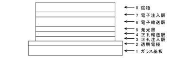
- FIG. 6 is a view showing a laminated structure of organic EL elements produced in Examples 8 to 14 and Comparative Examples 1 and 2.
- an electron transporting compound having an anthracene ring skeleton and a pyridoindole ring skeleton is used for forming an electron transporting layer.
- an electron transporting compound having an anthracene ring skeleton and a pyridoindole ring skeleton is used for forming an electron transporting layer.
- the compound of general formula (1) and the compound of general formula (2) differ only in the bonding position of the anthracene ring to which the pyridoindole ring is linked, In this respect, both have substantially the same structure. That is, the compound of the general formula (1) has a pyridoindole ring linked to the 9th or 10th position of the anthracene ring, whereas the compound of the general formula (2) has a 9th and 10th position of the anthracene ring. It has a structure in which a pyridoindole ring is linked to a position other than the position.
- p and divalent group A in general formula (1) correspond to q and divalent group B in general formula (2)
- Ar 1 and Ar 2 in general formula (1) are represented by general formula ( This corresponds to Ar 3 , Ar 4 and Ar 5 in 2).
- R 1 to R 8 in the general formula (1) correspond to R 9 to R 16 in the general formula (2)
- r 8 in the general formula (1) corresponds to r 16 in the general formula (2).
- p and q represent the number of divalent groups A and B, and are integers of 0 to 4. That is, these electron transporting compounds have a structure in which an anthracene ring and a pyridoindole ring are bonded by a divalent group A or B.
- p or q is zero, the divalent group A or B does not exist, and the anthracene ring and the pyridoindole ring are directly bonded by a single bond.
- the plurality of groups A or B are It may be different.
- Such divalent groups A and B are aromatic hydrocarbon ring groups or aromatic heterocyclic groups, and these ring groups may have a monocyclic structure or a condensed polycyclic structure. You may have.
- examples of the aromatic hydrocarbon ring forming the above ring group include a benzene ring, a naphthalene ring, an anthracene ring, a phenanthrene ring, an indene ring, and a pyrene ring
- examples of the aromatic heterocyclic ring include pyridine And a ring, a pyrimidine ring, a quinoline ring, an isoquinoline ring, a benzimidazole ring, a pyrazole ring, a carbazole ring, a naphthyridine ring, a phenatridine ring, and an acridine ring.
- the above aromatic hydrocarbon ring group and aromatic heterocyclic group may have a substituent as long as the electron transport property of the compound is not impaired, and such a substituent includes deuterium.
- a substituent includes deuterium. Examples thereof include an atom, a fluorine atom, a chlorine atom, a cyano group, a trifluoromethyl group, an alkyl group having 1 to 6 carbon atoms, an aromatic hydrocarbon group, and an aromatic heterocyclic group.
- the alkyl group having 1 to 6 carbon atoms may be linear or branched, and specific examples thereof include a methyl group, an ethyl group, an n-propyl group, Examples thereof include isopropyl group, n-butyl group, isobutyl group, tert-butyl group, n-pentyl group, isopentyl group, neopentyl group, n-hexyl group and the like.
- aromatic hydrocarbon group examples include a phenyl group, a biphenylyl group, a terphenylyl group, a tetrakisphenyl group, a styryl group, a naphthyl group, an anthryl group, an acenaphthenyl group, a fluorenyl group, and a phenanthryl group. it can.
- said substituent may have a substituent further.
- a quinone structure may be formed.
- the fluorenone ring may be a divalent group A or B.
- Ar 1 in the general formula (1) and Ar 3 in the general formula (2) represent an aromatic hydrocarbon group or an aromatic heterocyclic group (these are monovalent groups), and these groups are all It may have a condensed polycyclic structure.
- the aromatic hydrocarbon group include a phenyl group, a biphenylyl group, a terphenylyl group, a tetrakisphenyl group, a styryl group, a naphthyl group, an anthryl group, an acenaphthenyl group, a fluorenyl group, and a phenanthryl group.
- aromatic heterocyclic group examples include indenyl group, pyrenyl group, pyridyl group, pyrimidyl group, furanyl group, pyronyl group, thienyl group, quinolyl group, isoquinolyl group, benzofuranyl group, benzothienyl group, indolyl group, carbazolyl group, A benzoxazolyl group, a benzothiazolyl group, a quinoxalyl group, a benzimidazolyl group, a pyrazolyl group, a dibenzofuranyl group, a dibenzothienyl group, a naphthyridinyl group, a phenanthrolinyl group, an acridinyl group, and the like can be given.
- aromatic hydrocarbon groups and aromatic heterocyclic groups may have a substituent as long as they do not adversely affect the electron transport property.
- substituents include a deuterium atom, a fluorine atom, a chlorine atom, a cyano group, a trifluoromethyl group, a hydroxyl group, a nitro group, a linear or branched alkyl group having 1 to 6 carbon atoms, and a cyclopentyl group.
- Cyclohexyl group linear or branched alkoxy group having 1 to 6 carbon atoms, dialkylamino group substituted with linear or branched alkyl group having 1 to 6 carbon atoms, phenyl group, naphthyl group , Anthryl group, fluorenyl group, styryl group, pyridyl group, pyridoindolyl group, quinolyl group, and benzothiazolyl group, and these substituents may be further substituted.
- Ar 2 in the general formula (1) and Ar 4 and Ar 5 in the general formula (2) each represent an aromatic hydrocarbon group, and this aromatic hydrocarbon group may also have a condensed polycyclic structure.
- aromatic hydrocarbon groups are the same as those exemplified for Ar 1 and Ar 3 above, for example, phenyl group, biphenylyl group, terphenylyl group, tetrakisphenyl group, styryl group, naphthyl group, anthryl group, acenaphthenyl group. Group, fluorenyl group, phenanthryl group and the like.
- these aromatic hydrocarbon groups may also have the same substituents as those exemplified for Ar 1 and Ar 3 above, and these substituents may further have a substituent.
- R 1 to R 7 and R 9 to R 15 are each a hydrogen atom, deuterium atom, fluorine atom, chlorine atom, cyano group, trifluoromethyl group, unsubstituted alkyl group having 1 to 6 carbon atoms, A substituted or substituted aromatic hydrocarbon group or an aromatic heterocyclic group is represented.
- R 9 to R 15 in the general formula (2) are the same as R 1 to R 7 .
- the unsubstituted alkyl group having 1 to 6 carbon atoms is the same as the alkyl group mentioned as the substituent that the divalent group A may have.
- the aromatic hydrocarbon group and the aromatic heterocyclic group are the same groups as those described above with respect to Ar 1 , and the substituents that these groups may have have also been described with respect to Ar 1 . It is the same as that.
- R 8 of the general formula (1) represents the number of R 8 capable of binding to the anthracene ring, it represents an integer of 0-8.
- r 16 in the general formula (2) represents the number of R 8 that can be bonded to the anthracene ring of R 16 and represents an integer of 0 to 7.
- R 8 and R 16 represent a deuterium atom, a fluorine atom, a chlorine atom, a cyano group, a trifluoromethyl group, or an unsubstituted alkyl group having 1 to 6 carbon atoms, and r 8 and r 16 are When the number is 2 or more, the plurality of R 8 and R 16 may be the same as or different from each other.
- the unsubstituted alkyl group is the same as the alkyl group mentioned as the substituent that the above-described divalent groups A and B may have.
- the atoms W, X, Y, and Z that form part of the pyridoindole ring are the nitrogen atoms in any one of the general formulas (1) and (2). And the others are carbon atoms.
- Y is a carbon atom
- W, X, and Z are nitrogen atoms.
- any of the groups R 1 to R 4 (including a hydrogen atom) is bonded to the carbon atom constituting the ring, but the groups R 1 to R 4 are not bonded to the nitrogen atom. Neither hydrogen atom is bonded.
- a suitable electron transporting compound of the general formula (1) for example, in the electron transporting compound represented by the general formula (1), for example, the position where the anthracene ring is bonded to the pyridoindole ring is fixed at the position represented by the following formula (1a). Preferably it is.
- Y is preferably a nitrogen atom, and the anthracene ring and the pyridoindole ring are connected by a single bond.
- Suitable electron transporting compounds having such a structure are represented, for example, by the following general formulas (1b) to (1g).
- a suitable electron transporting compound of the general formula (2) in the electron transporting compound represented by the general formula (2) described above, a pyridoindole ring is bonded to the 2-position of the anthracene ring, for example, as shown in the following formula (2a). Further, it is preferable that the position where the anthracene ring is bonded to the pyridoindole ring is fixed at the position represented by the following formula (2b).
- B, Ar 3 to Ar 5 , R 9 to R 16 , q and r 16 , W, X, Y and Z are as described in the general formula (2).
- Y is a nitrogen atom among the ring constituent atoms W to Z, and the anthracene ring and the pyridoindole ring are connected by a single bond.
- Q 0
- Suitable electron transporting compounds having such a structure are represented, for example, by the following general formulas (2c) to (2e).
- Ar 3 to Ar 5 , R 9 , R 10 , and R 12 to R 15 are as described in the general formula (2).
- the electron transporting compound represented by the general formula (1) or (2) described above is a novel compound, and these compounds can be synthesized, for example, as follows.
- a corresponding pyridoindole derivative is synthesized by subjecting a corresponding halogenoanilinopyridine to a palladium-catalyzed cyclization reaction (see, for example, J. Chem. Soc., Perkin Trans. 1, 1505 (1999)).
- an aryl group (Ar 1 , Ar 3 ) is present at the corresponding 5-position by performing a condensation reaction such as an Ullmann reaction or Buchwald-Hartwig reaction with various aromatic hydrocarbon compounds or halides of aromatic heterocyclic compounds.
- the introduced pyridoindole derivative can be synthesized.
- the pyridoindole derivative thus synthesized can be brominated using N-bromosuccinimide or the like to synthesize the corresponding bromo compound.
- a bromo compound of such a pyridoindole derivative and a boronic acid or boronic acid ester having an anthracene ring structure synthesized by a known method (see, for example, J. Org.
- the above-described electron transporting compound having an anthracene ring skeleton and a pyridoindole ring skeleton can be synthesized.
- a cross-coupling reaction such as coupling
- the above-described electron transporting compound having an anthracene ring skeleton and a pyridoindole ring skeleton can be synthesized.
- a corresponding boronic acid or boronic acid ester from the bromo form of the above pyridoindole derivative, and reacting this with a dihalide of an aromatic hydrocarbon or an aromatic heterocyclic ring, a halogenated aryl group was bonded.
- the aforementioned anthracene ring skeleton and pyridoindole ring skeleton can also be obtained by performing a cross-coupling reaction such as Suzuki coupling on the boronic acid or boronic acid ester having the anthracene ring structure after the pyridoindole derivative is obtained.
- the electron transporting compound can be synthesized.
- ⁇ Arylamine compound ( ⁇ )> an arylamine compound having a molecular structure in which three or more triphenylamine skeletons are bonded by a single bond or a divalent hydrocarbon group (that is, a divalent group not containing a hetero atom) ( ⁇ ) To form a hole injection layer.
- This arylamine compound ( ⁇ ) has a higher hole mobility than the arylamine compound ( ⁇ ) described later.
- Such an arylamine compound ( ⁇ ) is, for example, a trimer or a tetramer of various triphenylamines, and has four triphenylamine skeletons particularly in terms of high hole mobility. Is preferred.
- Examples of the arylamine having four triphenylamine skeletons include those represented by the following general formula (3).
- r 17 to r 28 indicate the number of groups R 17 to R 28 that can be bonded to each benzene ring in the molecule, and of these, r 17 , r 18 , r 21 , r 24 , r 27 and r 28 each represents an integer of 0 to 5.
- R 19 , r 20 , r 22 , r 23 , r 25 and r 26 each represents an integer of 0 to 4. That is, a value of r 17 to r 28 of 0 means that the groups R 17 to R 28 are not bonded to the benzene ring.
- R 17 to R 28 are each a deuterium atom, a fluorine atom, a chlorine atom, a cyano group, a trifluoromethyl group, an unsubstituted alkyl group having 1 to 6 carbon atoms, an unsubstituted or substituted group having 2 to 6 carbon atoms
- the unsubstituted alkyl group having 1 to 6 carbon atoms may be linear or branched, and examples thereof include a methyl group, an ethyl group, an n-propyl group, an isopropyl group, Examples thereof include n-butyl group, isobutyl group, tert-butyl group, n-pentyl group, isopentyl group, neopentyl group, n-hexyl group and the like.
- the unsubstituted alkenyl group having 2 to 6 carbon atoms may be linear or branched, and examples thereof include a vinyl group, an allyl group, an isopropenyl group, and a 2-butenyl group.
- aromatic hydrocarbon group examples include phenyl group, biphenylyl group, terphenylyl group, tetrakisphenyl group, styryl group, naphthyl group, anthryl group, acenaphthenyl group, fluorenyl group, phenanthryl group and the like.
- Aromatic heterocyclic groups include indenyl, pyrenyl, pyridyl, pyrimidyl, furanyl, pyronyl, thienyl, quinolyl, isoquinolyl, benzofuranyl, benzothienyl, indolyl, carbazolyl, benzox Examples include zolyl group, benzothiazolyl group, quinoxalyl group, benzimidazolyl group, pyrazolyl group, dibenzofuranyl group, dibenzothienyl group, naphthyridinyl group, phenanthrolinyl group, acridinyl group and the like.
- any of the above alkenyl groups, aromatic hydrocarbon groups and aromatic heterocyclic groups may have a substituent.
- substituents include deuterium atom, fluorine atom, chlorine atom, trifluoromethyl group, alkyl group having 1 to 6 carbon atoms, phenyl group, biphenylyl group, terphenylyl group, tetrakisphenyl group, styryl group, naphthyl group.
- a fluorenyl group, a phenanthryl group, an indenyl group, and a pyrenyl group, and these substituents may further have a substituent.
- R 17 to R 28 when a plurality of R 17 to R 28 are bonded to each other to form a ring, they may be bonded to each other via a single bond to form a ring, or have a substituent.
- the ring may be bonded to each other via a methylene group, an oxygen atom or a sulfur atom which may be present. In particular, it is preferable that they are bonded to each other via a dimethylmethylene group to form a ring.
- At least one of R 17 to R 28 is a deuterium atom, or a group containing a deuterium atom, for example, an alkenyl group, an aromatic hydrocarbon group or an aromatic group having a deuterium atom as a substituent. It is preferably a heterocyclic group.
- E 1 to E 3 correspond to the bonding portion between the triphenylamine skeletons and represent a single bond or a divalent hydrocarbon group.
- Examples of the divalent hydrocarbon group, that is, a divalent group not containing a hetero atom include the following formula:
- n1 represents an integer of 1 ⁇ 3
- r 29, r 30, r 31 indicating the number of R 29, R 30 and R 31 are each, 0 ⁇ Represents an integer of 4.
- R 29 , R 30 and R 31 each represent the same atom or group as R 17 to R 28 .
- arylamine compound ( ⁇ ) of the general formula (3) Specific examples of the arylamine compound ( ⁇ ) of the general formula (3); Specific examples of the arylamine compound ( ⁇ ) represented by the general formula (3) described above include, but are not limited to, the following compounds (3-1) to (3-23): Among these, the triarylamine (having four triphenylamine skeletons) represented by the general formula (3) described above is particularly preferable.
- triphenylamine skeleton as shown by the following (3′-1) to (3′-7) is not included, although it does not have four triphenylamine skeletons represented by the general formula (3).
- a compound having three of these can also be suitably used for forming a hole injection layer as an arylamine compound ( ⁇ ).
- ⁇ Arylamine compound ( ⁇ )> two triphenylamine skeletons are bonded by a single bond or a divalent hydrocarbon group (that is, a divalent group not containing a hetero atom) as a compound that forms a hole transport layer.
- An arylamine compound ( ⁇ ) having a molecular structure is used.
- Such an arylamine compound ( ⁇ ) is represented, for example, by the following general formula (4).
- r 32 to r 37 indicate the number of groups R 32 to R 37 that can be bonded to the benzene ring in the molecule, and r 32 , r 33 , r 36 , and r 37 are , 0 to 5 and r 34 and r 35 each represents an integer of 0 to 4. That is, when the values of r 32 to r 37 are 0, it means that the groups R 32 to R 37 are not bonded to the benzene ring.
- R 32 to R 37 are each a deuterium atom, a fluorine atom, a chlorine atom, a cyano group, a trifluoromethyl group, an unsubstituted alkyl group having 1 to 6 carbon atoms, an unsubstituted or substituted group having 1 to 6 carbon atoms An alkenyl group, an unsubstituted or substituted aromatic hydrocarbon group, or an unsubstituted or substituted aromatic heterocyclic group; Further, those having a plurality of R 32 to R 37 (when r 32 to r 37 is 2 or more) may be bonded to each other to form a ring.
- the unsubstituted alkyl group having 1 to 6 carbon atoms or the unsubstituted alkenyl group having 2 to 6 carbon atoms may be linear or branched. Examples thereof include the same alkyl group and alkenyl group as those exemplified for R 17 to R 28 in (3). Specific examples of the aromatic hydrocarbon group or aromatic heterocyclic group include the same groups as in R 17 to R 28 .
- alkenyl group, aromatic hydrocarbon group and aromatic heterocyclic group may have a substituent, and such a substituent may be the same as the substituents listed for R 17 to R 28. Can be mentioned.
- a plurality of groups R 32 to R 37 when bonded to each other to form a ring, they may be bonded to each other via a single bond to form a ring or have a substituent. And may be bonded to each other via a methylene group, an oxygen atom or a sulfur atom which may be formed to form a ring. In particular, it is preferable that they are bonded to each other via a dimethylmethylene group to form a ring.
- At least one of R 32 to R 37 is a deuterium atom or a substituent containing a deuterium atom (for example, an alkenyl group having a deuterium atom as a substituent, an aromatic hydrocarbon group and an aromatic heterocyclic group). ) Is preferable.
- E 4 are the same as E 1 ⁇ E 3 in the general formula (3) described above, a single bond or a divalent hydrocarbon group.
- This divalent hydrocarbon group has the following formula as described for E 1 to E 3 above: It is represented by
- n1 represents an integer of 1 to 3
- r 29 , r 30 and r 31 representing the numbers of R 29 , R 30 and R 31 represent an integer of 0 to 4, respectively.
- R 29 , R 30 and R 31 each represent the same atom or group as R 17 to R 28 .
- arylamine compound ( ⁇ ) of the general formula (4) Specific examples of the arylamine compound ( ⁇ ) of the general formula (4); Specific examples of the arylamine compound ( ⁇ ) represented by the general formula (4) described above are not limited thereto, but examples thereof include the following compounds (4-1) to (4-23): Can be mentioned.
- compounds having two triphenylamine skeletons as shown in the following (4′-1) and (4′-2) are also arylamine compounds ( ⁇ ) can be suitably used for forming a hole transport layer.
- the organic EL device of the present invention has a basic structure in which a hole injection layer, a hole transport layer, a light emitting layer, and an electron transport layer are formed in this order between an anode and a cathode.
- the hole injection layer is formed of an arylamine compound ( ⁇ ) having a triphenylamine skeleton
- the hole transport layer is formed of an arylamine compound ( ⁇ ) having a triphenylamine skeleton
- the transport layer has a structure in which the transport layer is formed of the electron transporting compound represented by the general formula (1) or (2).
- each layer which comprises this organic EL element is demonstrated.
- the anode is provided by vapor deposition on a transparent substrate such as a transparent plastic substrate (for example, a polyethylene terephthalate substrate) or a glass substrate, and an electrode material having a large work function such as ITO or gold. It is formed by.
- a transparent substrate such as a transparent plastic substrate (for example, a polyethylene terephthalate substrate) or a glass substrate
- an electrode material having a large work function such as ITO or gold. It is formed by.
- a metal having a low work function such as aluminum, or an alloy having a lower work function such as a magnesium silver alloy, a magnesium indium alloy, or an aluminum magnesium alloy is used as an electrode material.
- the hole injection layer is formed of the above-described arylamine compound ( ⁇ ), that is, a compound having three or more triphenylamine skeletons in the molecule. That is, the arylamine compound ( ⁇ ) has a very high hole mobility and can maintain a thin film state stably. Therefore, by forming the hole injection layer using such a compound, it is possible to improve the light emission efficiency, reduce the driving voltage, and extend the life.
- arylamine compound ( ⁇ ) that is, a compound having three or more triphenylamine skeletons in the molecule. That is, the arylamine compound ( ⁇ ) has a very high hole mobility and can maintain a thin film state stably. Therefore, by forming the hole injection layer using such a compound, it is possible to improve the light emission efficiency, reduce the driving voltage, and extend the life.
- hole injection layer forming materials for example, porphyrins typified by copper phthalocyanine, as long as performance such as luminous efficiency, driving voltage, and durability are not impaired.
- a compound; an acceptor heterocyclic compound such as hexacyanoazatriphenylene; another coating type (organic solvent-soluble) polymer material or the like may be used in combination with the arylamine compound ( ⁇ ).
- Such other compounds can form a hole injection layer in the form of a mixture with the arylamine compound ( ⁇ ), and in this case, the amount should be a small amount of 50% by weight or less per the arylamine compound ( ⁇ ). It is.
- one or a plurality of layers of other compounds can be provided in the form of being laminated on the layer formed of the arylamine compound ( ⁇ ).
- the hole transport layer provided adjacent to the hole injection layer is formed of the arylamine compound ( ⁇ ) and the compound having two triphenylamine skeletons in the molecule.
- This hole transport layer may also be used in combination with another hole transport compound other than the arylamine compound ( ⁇ ), similarly to the hole injection layer described above.
- Such other compounds can form the hole transport layer in the form of a mixture with the arylamine compound ( ⁇ ), and in this case, the amount is within a range that does not impair the performance of the organic EL device of the present invention. (For example, 50% by weight or less per arylamine compound ( ⁇ )) should be used in combination.
- one or more layers of other hole transporting compounds can be provided in the form of being laminated on the layer formed of the arylamine compound ( ⁇ ).
- the light emitting layer is the same as that used in conventionally known organic EL elements, for example, metal complexes of quinolinol derivatives such as Alq 3 , complexes of various metals such as zinc, beryllium, and aluminum, anthracene derivatives,
- the light-emitting layer can be formed using a light-emitting material such as a bisstyrylbenzene derivative, a pyrene derivative, an oxazole derivative, or a polyparaphenylene vinylene derivative.
- the light emitting layer can be formed using a compound having an anthracene skeleton and a pyridoindole skeleton represented by the general formula (1) or (2).
- the light emitting layer can be formed using a host material and a dopant material (guest material).
- a host material a thiazole derivative, a benzimidazole derivative, a polydialkylfluorene derivative, or the like can be used in addition to the above light emitting material.
- a dopant material quinacridone, coumarin, rubrene, perylene and derivatives thereof, benzopyran derivatives, rhodamine derivatives, aminostyryl derivatives, and the like can be used.
- a phosphorescent emitter can be used as the guest material.
- a phosphorescent emitter of a metal complex such as iridium or platinum can be used.
- a green phosphorescent emitter such as Ir (ppy) 3
- a blue phosphorescent emitter such as FIrpic or FIr6
- a red phosphorescent emitter such as Btp 2 Ir (acac)
- a hole injecting / transporting host material such as 4,4′-di (N-carbazolyl) biphenyl (CBP), carbazole derivatives such as TCTA, mCP and the like can be used.
- Electron transport properties such as bis (triphenylsilyl) benzene (UGH2), 2,2 ′, 2 ′′-(1,3,5-phenylene) -tris (1-phenyl-1H-benzimidazole) (TPBI)
- UHM2 bis (triphenylsilyl) benzene
- TPBI 1,3,5-phenylene
- Host materials can also be used. By using such a host material, a high-performance organic EL element can be produced.
- the host material of the phosphorescent emitter is preferably doped by co-evaporation in the range of 1 to 30 weight percent with respect to the entire light emitting layer.
- the light emitting layer is not limited to a single layer structure, and may have a laminated structure in which layers formed using the various compounds described above are laminated.
- the electron transport layer is formed using the electron transport compound represented by the general formula (1) or the general formula (2) described above. That is, this electron transporting compound has an anthracene skeleton and a pyridoindole skeleton, and by forming an electron transporting layer using the electron transporting compound having such a structure, the hole injection layer described above is formed. In addition, a balance with the hole injection / transport characteristics of the hole transport layer can be secured, and an organic EL element exhibiting excellent performance in terms of light emission efficiency, drive voltage, and durability (long life) can be obtained.
- the electron transport layer in addition to the electron transport compounds described above, for example, metal complexes of quinolinol derivatives such as Alq 3 , various metal complexes such as zinc, beryllium, and aluminum, triazole derivatives, triazine derivatives , Known electron transporting materials such as oxadiazole derivatives, thiadiazole derivatives, carbodiimide derivatives, quinoxaline derivatives, phenanthroline derivatives, and silole derivatives can be used in combination. Such other electron transporting material can form an electron transporting layer in the form of a mixture with the electron transporting compound of the general formula (1) or the general formula (2).
- the amount of the electron transporting material used should be a small amount within the range that does not impair the excellent characteristics obtained in the present invention, and is 50% by weight per electron transporting compound of the general formula (1) or the general formula (2). The following is recommended.
- one or more layers of other electron transporting materials can be provided in the form of being stacked on the layer formed of the electron transporting compound of the general formula (1) or the general formula (2).
- the hole injection layer, the hole transport layer, and the electron transport layer are formed using the specific compound described above, other layers may be provided as necessary. it can.
- an electron blocking layer can be provided between the hole transport layer and the light emitting layer
- a hole blocking layer can be provided between the light emitting layer and the electron transport layer
- An electron injection layer can be provided between the cathode and the cathode.
- Electron blocking layer is provided to prevent injected electrons from passing through the light emitting layer.
- various compounds having an electron blocking property can be used, and the following carbazole derivatives are typical. 4,4 ′, 4 ′′ -tri (N-carbazolyl) triphenylamine (TCTA); 9,9-bis [4- (carbazol-9-yl) phenyl] fluorene; 1,3-bis (carbazol-9-yl) benzene (mCP); 2,2-bis (4-carbazol-9-ylphenyl) adamantane (Ad-Cz);
- TCTA N-carbazolyl triphenylamine
- mCP 1,3-bis (carbazol-9-yl) benzene
- Ad-Cz 2,2-bis (4-carbazol-9-ylphenyl) adamantane
- a triphenylsilyl group represented by 9- [4- (carbazol-9-yl) phenyl] -9- [
- the hole blocking layer is provided to prevent injected holes from passing through the light emitting layer, and includes a phenanthroline derivative such as bathocuproine (BCP), aluminum (III) bis (2-methyl- In addition to metal complexes of quinolinol derivatives such as 8-quinolinato) -4-phenylphenolate (BAlq), various rare earth complexes, triazole derivatives, triazine derivatives, oxadiazole derivatives, etc.
- BCP bathocuproine
- BAlq aluminum (III) bis (2-methyl-
- quinolinol derivatives such as 8-quinolinato) -4-phenylphenolate (BAlq)
- various rare earth complexes such as triazole derivatives, triazine derivatives, oxadiazole derivatives, etc.
- Electron injection layer can be formed using an alkali metal salt such as lithium fluoride or cesium fluoride, an alkaline earth metal salt such as magnesium fluoride, or a metal oxide such as aluminum oxide.
- an alkali metal salt such as lithium fluoride or cesium fluoride
- an alkaline earth metal salt such as magnesium fluoride
- a metal oxide such as aluminum oxide.
- the organic EL device of the present invention having the structure described above includes, for example, an anode, a cathode, a hole injection layer between the anode and the cathode, a hole transport layer, a light emitting layer, an electron transport layer, and an electron blocking layer provided as appropriate.
- a hole blocking layer, an electron injection layer, and the like can be produced by forming a film on a transparent substrate by a known method such as a vapor deposition method, a spin coating method, or an ink jet method, depending on the type of the material.
- Example 1 Synthesis of 8- (9,10-diphenylanthracen-2-yl) -5-phenyl-5H-pyrido [4,3-b] indole [compound (2-1)]; In a reaction vessel purged with nitrogen, 43.0 ml of iodobenzene, 5H-pyrido [4,3-b] indole 50.0 g, 1.9 g of copper powder, 82.2g of potassium carbonate, 2.1 ml of dimethyl sulfoxide, The mixture was heated and stirred at 170 ° C. for 3 hours.
- the organic phase was dehydrated with anhydrous magnesium sulfate and then concentrated under reduced pressure to obtain a crude product.
- the crude product was purified by column chromatography (carrier: NH silica gel, eluent: toluene / hexane), and 8- (9,10-diphenylanthracen-2-yl) -5-phenyl-5H-pyrido [4,3- b] 3.0 g (yield 61%) of a yellow powder of indole [compound (2-1)] was obtained.
- Example 2 Synthesis of 8- [9,10-di (naphthalen-2-yl) -anthracen-2-yl] -5-phenyl-5H-pyrido [4,3-b] indole [compound (2-2)]; Using the bromide of pyridoindole obtained in Example 1 (8-bromo-5-phenyl-5H-pyrido [4,3-b] indole, synthesis was performed as follows.
- Example 3 Synthesis of 8- [4- [10- (naphthalen-2-yl) anthracen-9-yl] phenyl] -5-phenyl-5H-pyrido [4,3-b] indole [compound (1-6)]; 8- (4-Bromophenyl) -5-phenyl-5H-pyrido [4,3-b] indole was synthesized and this pyridoindole derivative was used as a raw material.
- Example 4 Synthesis of 8- [3- [10- (naphthalen-2-yl) anthracen-9-yl] phenyl] -5-phenyl-5H-pyrido [4,3-b] indole [compound (1-11)]; In the same manner as in Example 3, 8- (3-chlorophenyl) -5-phenyl-5H-pyrido [4,3-b] indole was synthesized and this pyridoindole derivative was used as a raw material.
- the crude product was purified by column chromatography (carrier: NH silica gel, eluent: toluene / hexane) and 8- [3- [10- (naphthalen-2-yl) anthracen-9-yl] phenyl] -5-phenyl 1.81 g (yield 36.2%) of a yellowish white powder of -5H-pyrido [4,3-b] indole [compound (1-11)] was obtained.
- Example 5 Synthesis of 8- [4- [10-phenylanthracen-9-yl] naphthalen-1-yl] -5-phenyl-5H-pyrido [4,3-b] indole [compound (1-15)]; In the same manner as in Example 3, 8- (4-bromonaphthalen-1-yl) -5-phenyl-5H-pyrido [4,3-b] indole) was synthesized, and this pyridoindole derivative was used as a raw material.
- Example 6 8- [4- [10- (Naphthalen-1-yl) anthracen-9-yl] naphthalen-1-yl] -5-phenyl-5H-pyrido [4,3-b] indole [compound (1-17) ] Synthesis; As in Example 5, the following synthesis reaction was performed using a pyridoindole derivative (8- (4-bromonaphthalen-1-yl) -5-phenyl-5H-pyrido [4,3-b] indole). It was.
- the crude product was crystallized with a mixed solvent of toluene and hexane, adsorbed and purified with silica gel, washed with methanol, crystallized with a mixed solvent of toluene and hexane, and crystallized with a mixed solvent of toluene and methanol.
- Example 7 8- [4- [10- (Naphthalen-2-yl) anthracen-9-yl] naphthalen-1-yl] -5-phenyl-5H-pyrido [4,3-b] indole [compound (1-18) ] Synthesis; As in Example 5, the following synthesis reaction was performed using a pyridoindole derivative (8- (4-bromonaphthalen-1-yl) -5-phenyl-5H-pyrido [4,3-b] indole). It was.
- the crude product is purified by column chromatography (carrier: NH silica gel, eluent: toluene / hexane), then crystallized with a mixed solvent of toluene and hexane, washed with methanol, and crystallized with a mixed solvent of acetone and methanol.
- Example 8 The organic EL element having the structure shown in FIG. 1 was produced by the following procedure. That is, this organic EL element is formed on a glass substrate 1 with a transparent anode 2 (ITO electrode), a hole injection layer 3, a hole transport layer 4, a light emitting layer 5, an electron transport layer 6, an electron injection layer 7, a cathode (aluminum). Electrode) 8 has a structure provided in order by vapor deposition.
- ITO electrode transparent anode 2
- Electrode 8 has a structure provided in order by vapor deposition.
- the glass substrate 1 on which a 150 nm-thick ITO (Indium Tin Oxide) film is formed is subjected to ultrasonic cleaning in isopropyl alcohol for 20 minutes and then dried on a hot plate heated to 200 ° C. for 10 minutes. It was. Then, after performing UV ozone treatment for 5 minutes, this glass substrate with ITO was attached in a vacuum evaporation machine, and pressure was reduced to 0.001 Pa or less. Subsequently, a hole injection layer 3 having a thickness of 20 nm was formed so as to cover the transparent anode 2 by vapor deposition using the following compound (3-1).
- ITO Indium Tin Oxide
- a hole transport layer 4 having a thickness of 40 nm was formed by vapor deposition using the following compound (4-1).
- the following compound (5) and the following compound (6) are subjected to binary vapor deposition at a vapor deposition rate of 5:95 to form a light emitting layer 5 having a thickness of 30 nm. did.
- An electron transport layer 6 having a thickness of 30 nm was formed on the light emitting layer 5 by vapor deposition using the following compound (2-1).
- lithium fluoride was deposited as an electron injection layer 7 so as to have a film thickness of 0.5 nm. Finally, 150 nm of aluminum was deposited to form the cathode 8.
- Table 1 summarizes the measurement results of the light emission characteristics when a DC voltage was applied to the produced organic EL element.
- Example 9 An organic EL device was produced under the same conditions as in Example 8, except that Compound 2-2 having the following structural formula was used instead of Compound 2-1 to form an electron transport layer 6 having a thickness of 30 nm.
- Table 1 summarizes the measurement results of the light emission characteristics when a DC voltage was applied to the produced organic EL element.
- Example 10 An organic EL device was produced under the same conditions as in Example 8 except that the compound 1-6 having the following structural formula was used in place of the compound 2-1, and the electron transport layer 6 having a thickness of 30 nm was formed.
- Table 1 summarizes the measurement results of the light emission characteristics when a DC voltage was applied to the produced organic EL element.
- Example 11 An organic EL device was produced under the same conditions as in Example 8, except that Compound 1-11 having the following structural formula was used instead of Compound 2-1, and an electron transport layer 6 having a thickness of 30 nm was formed.
- Table 1 summarizes the measurement results of the light emission characteristics when a DC voltage was applied to the produced organic EL element.
- Example 12 An organic EL device was produced under the same conditions as in Example 8, except that Compound 1-15 having the following structural formula was used in place of Compound 2-1 to form an electron transport layer 6 having a thickness of 30 nm.
- Table 1 summarizes the measurement results of the light emission characteristics when a DC voltage was applied to the produced organic EL element.
- Example 13 An organic EL device was produced under the same conditions as in Example 8, except that Compound 1-17 having the following structural formula was used instead of Compound 2-1 to form an electron transport layer 6 having a thickness of 30 nm.
- Table 1 summarizes the measurement results of the light emission characteristics when a DC voltage was applied to the produced organic EL element.
- Example 14 An organic EL device was produced under the same conditions as in Example 8 except that Compound 1-18 having the following structural formula was used instead of Compound 2-1 to form an electron transport layer 6 having a thickness of 30 nm.
- Table 1 summarizes the measurement results of the light emission characteristics when a DC voltage was applied to the produced organic EL element.
- Example 1 For comparison, an organic EL device was produced under the same conditions as in Example 8 except that Alq 3 was used instead of Compound 2-1 to form a 30 nm-thick electron transport layer 6. About the produced organic EL element, various characteristics were measured at normal temperature in air
- Example 2 For comparison, an organic EL device was produced under the same conditions as in Example 8 except that CuPc was used instead of compound 3-1 to form a 20 nm-thick hole injection layer 3. About the produced organic EL element, various characteristics were measured at normal temperature in air
- the organic EL element of the present invention can improve luminous efficiency and drive voltage can be reduced, thereby improving the durability of the organic EL element. For example, it can be used for home appliances and lighting applications. became.
Abstract
Description
また発光効率の更なる向上を目的として三重項励起子の利用が試みられ、燐光発光性化合物の利用も検討されている。 To date, many improvements have been made for practical application of organic EL elements. For example, various roles of the laminated structure are further subdivided, and a structure in which an anode, a hole injection layer, a hole transport layer, a light emitting layer, an electron transport layer, an electron injection layer, and a cathode are provided in this order on a substrate High efficiency and durability have been achieved with such devices.
Further, the use of triplet excitons has been attempted for the purpose of further improving the light emission efficiency, and the use of phosphorescent compounds has also been studied.
一方、正孔輸送材料としては、ベンジジン骨格を含むアリールアミン系材料が用いられてきた(特許文献3参照)。 As hole injection materials used in organic EL elements, phthalocyanines such as copper phthalocyanine (CuPc) were proposed at the beginning (see, for example, Patent Document 1). A material having a diamine structure has been widely used (see Patent Document 2).
On the other hand, arylamine materials containing a benzidine skeleton have been used as the hole transport material (see Patent Document 3).
前記正孔注入層が、3個以上のトリフェニルアミン骨格が単結合または2価の炭化水素基で結合されている分子構造を有するアリールアミン化合物(α)を含み、
前記正孔輸送層が、2個のトリフェニルアミン骨格が単結合または2価の炭化水素基で結合されている分子構造を有するアリールアミン化合物(β)を含み、
前記電子輸送層が、下記一般式(1)または下記一般式(2)で表されるアントラセン環骨格とピリドインドール環骨格を有する電子輸送性化合物を含有すること、
を特徴とする有機エレクトロルミネッセンス素子が提供される。 According to the present invention, in an organic electroluminescence device in which a hole injection layer, a hole transport layer, a light emitting layer, and an electron transport layer are provided between an anode and a cathode,
The hole injection layer includes an arylamine compound (α) having a molecular structure in which three or more triphenylamine skeletons are bonded by a single bond or a divalent hydrocarbon group,
The hole transport layer includes an arylamine compound (β) having a molecular structure in which two triphenylamine skeletons are bonded by a single bond or a divalent hydrocarbon group;
The electron transport layer contains an electron transport compound having an anthracene ring skeleton and a pyridoindole ring skeleton represented by the following general formula (1) or the following general formula (2);
An organic electroluminescence device is provided.

pは、2価の基Aの数を示し、0~4の整数であり、
Aは、2価の無置換または置換芳香族炭化水素環基もしくは芳香族複
素環基を示し、但し、pが2以上であるとき、複数のAは互いに異なっ
ていてよく、pが0であるときは、Aは存在せず、アントラセン環とピ
リドインドール環とが単結合を介して結合しているものとし、
Ar1は、無置換または置換芳香族炭化水素基もしくは芳香族複素環
基を示し、
Ar2は、無置換または置換芳香族炭化水素基を示し、
R1~R7は、それぞれ、水素原子、重水素原子、フッ素原子、塩素
原子、シアノ基、トリフルオロメチル基、炭素原子数1ないし6の無置
換アルキル基、無置換または置換芳香族炭化水素基もしくは芳香族複素
環基を表し、
R8の数を示すr8は、0~8の整数を表し、
R8は、重水素原子、フッ素原子、塩素原子、シアノ基、トリフルオ
ロメチル基、または炭素原子数1ないし6の無置換アルキル基を表し、
r8が2以上の数であるとき複数のR8は互いに同一でも異なっていて
もよく、
W、X、Y及びZは、それぞれ、炭素原子または窒素原子を表すが、
そのいずれか1つのみが窒素原子であるものとし、この場合の窒素原子
にはR1~R4が結合していないものとする。 An electron transporting compound of the general formula (1);
p represents the number of divalent groups A and is an integer of 0 to 4,
A represents a divalent unsubstituted or substituted aromatic hydrocarbon ring group or an aromatic complex ring group, provided that when p is 2 or more, a plurality of A may be different from each other, and p is 0. In some cases, A does not exist, and the anthracene ring and the pyridoindole ring are bonded via a single bond.
Ar 1 represents an unsubstituted or substituted aromatic hydrocarbon group or aromatic heterocyclic group,
Ar 2 represents an unsubstituted or substituted aromatic hydrocarbon group,
R 1 to R 7 are each a hydrogen atom, a deuterium atom, a fluorine atom, a chlorine atom, a cyano group, a trifluoromethyl group, an unsubstituted alkyl group having 1 to 6 carbon atoms, an unsubstituted or substituted aromatic carbon Represents a hydrogen group or an aromatic heterocyclic group,
R 8 indicating the number of R 8 represents an integer of 0 to 8,
R 8 represents a deuterium atom, a fluorine atom, a chlorine atom, a cyano group, a trifluoromethyl group, or an unsubstituted alkyl group having 1 to 6 carbon atoms,
when r 8 is a number of 2 or more, the plurality of R 8 may be the same or different from each other;
W, X, Y and Z each represent a carbon atom or a nitrogen atom,
It is assumed that only one of them is a nitrogen atom, and in this case, R 1 to R 4 are not bonded to the nitrogen atom.
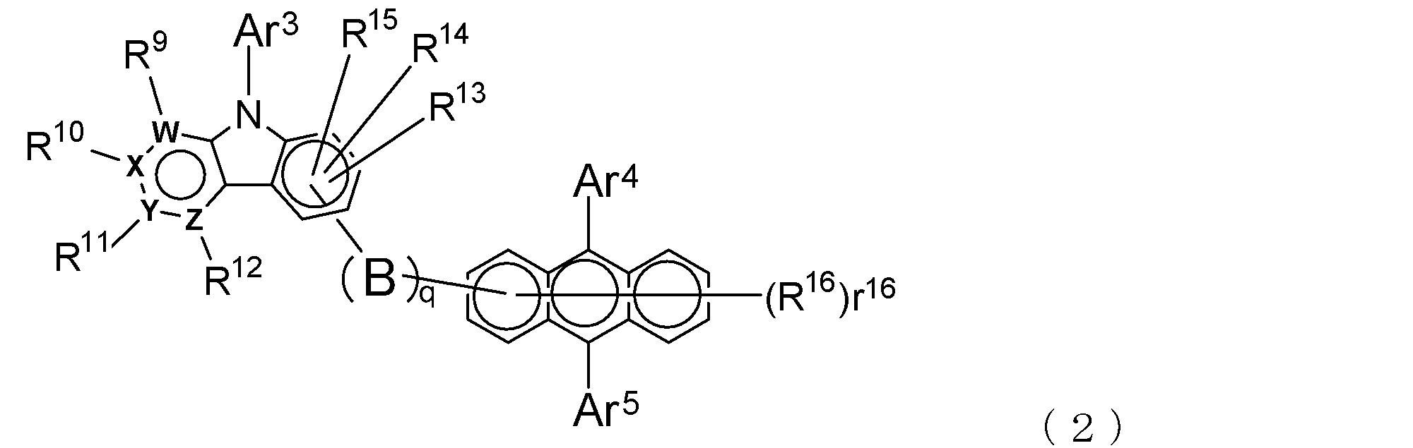
qは、2価の基Bの数を示し、0~4の整数であり、
Bは、2価の無置換または置換芳香族炭化水素環基もしくは芳香族複
素環基を示し、但し、qが2以上であるとき、複数のBは互いに異なっ
ていてよく、qが0であるときは、Bは存在せず、アントラセン環とピ
リドインドール環とが単結合を介して結合しているものとし、
Ar3は、無置換または置換芳香族炭化水素基もしくは芳香族複素環
基を示し、
Ar4及びAr5は、無置換または置換芳香族炭化水素基を示し、
R9~R15は、それぞれ、水素原子、重水素原子、フッ素原子、塩
素原子、シアノ基、トリフルオロメチル基、炭素原子数1ないし6の
無置換アルキル基、無置換または置換芳香族炭化水素基もしくは芳香
族複素環基を表し、
R16の数を示すr16は、0~7の整数を表し、
R16は、重水素原子、フッ素原子、塩素原子、シアノ基、トリフル
オロメチル基、または炭素原子数1ないし6の無置換アルキル基を表し
、r16が2以上の数であるとき、複数のR16は互いに同一でも異な
っていてもよく、
W、X、Y及びZは、それぞれ、炭素原子または窒素原子を表すが、
そのいずれか1つのみが窒素原子であるものとし、この場合の窒素原子
にはR9~R12が結合していないものとする。 An electron transporting compound of the general formula (2);
q represents the number of divalent groups B and is an integer of 0 to 4,
B represents a divalent unsubstituted or substituted aromatic hydrocarbon ring group or an aromatic complex ring group, provided that when q is 2 or more, a plurality of B may be different from each other, and q is 0. In some cases, B does not exist, and the anthracene ring and the pyridoindole ring are bonded via a single bond.
Ar 3 represents an unsubstituted or substituted aromatic hydrocarbon group or aromatic heterocyclic group,
Ar 4 and Ar 5 represent an unsubstituted or substituted aromatic hydrocarbon group,
R 9 to R 15 are each a hydrogen atom, a deuterium atom, a fluorine atom, a chlorine atom, a cyano group, a trifluoromethyl group, an unsubstituted alkyl group having 1 to 6 carbon atoms, an unsubstituted or substituted aromatic carbonized carbon Represents a hydrogen group or an aromatic heterocyclic group,
R 16 indicating the number of R 16 represents an integer of 0-7,
R 16 represents a deuterium atom, a fluorine atom, a chlorine atom, a cyano group, a trifluoromethyl group, or an unsubstituted alkyl group having 1 to 6 carbon atoms, and when r 16 is a number of 2 or more, a plurality of R 16 may be the same or different from each other,
W, X, Y and Z each represent a carbon atom or a nitrogen atom,
It is assumed that only one of them is a nitrogen atom, and in this case, R 9 to R 12 are not bonded to the nitrogen atom.

r17~r28は、それぞれR17~R28の数を示すものであり、
これらの内、r17、r18、r21、r24、r27及びr28は、
0~5の整数を表し、r19、r20、r22、r23、r25及び
r26は、0~4の整数を表し、
R17~R28は、それぞれ、重水素原子、フッ素原子、塩素原子、
シアノ基、トリフルオロメチル基、炭素原子数1ないし6の無置換ア
ルキル基、炭素原子数2ないし6の無置換もしくは置換アルケニル基
、無置換または置換芳香族炭化水素基もしくは芳香族複素環基であり
、これらの基の中で同一のベンゼン環に結合しているもの同士は、互
いに結合して環を形成していてもよく、
E1~E3は、それぞれ、単結合或いは下記式;
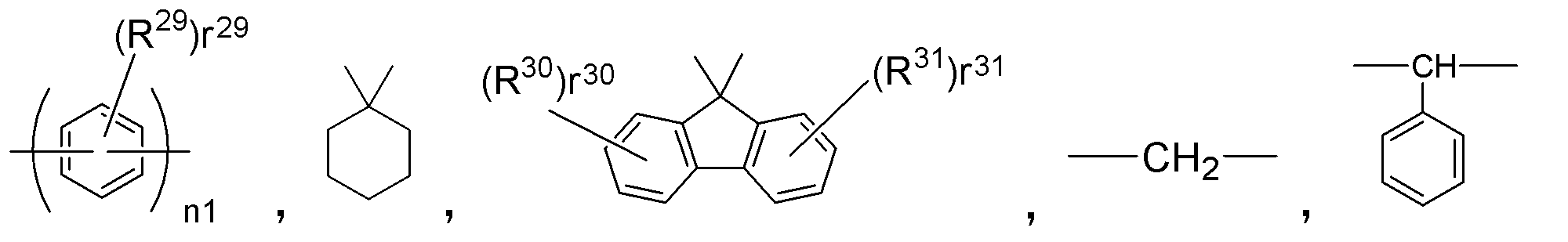
n1は、1~3の整数を表し、
R29、R30及びR31の数を示すr29、r30、r31は、そ
れぞれ、0~4の整数を表し、
R29、R30及びR31は、それぞれ、前記R17~R28と同様
の原子もしくは基を示す、
の何れかで表される2価の基を表す。 An arylamine compound (α) of the general formula (3);
r 17 to r 28 indicate the numbers of R 17 to R 28 , respectively.
Of these, r 17 , r 18 , r 21 , r 24 , r 27 and r 28 are:
R represents an integer of 0 to 5, r 19 , r 20 , r 22 , r 23 , r 25 and r 26 represent an integer of 0 to 4;
R 17 to R 28 are each a deuterium atom, a fluorine atom, a chlorine atom,
Cyano group, trifluoromethyl group, unsubstituted alkyl group having 1 to 6 carbon atoms, unsubstituted or substituted alkenyl group having 2 to 6 carbon atoms, unsubstituted or substituted aromatic hydrocarbon group or aromatic heterocyclic group Among these groups, those bonded to the same benzene ring may be bonded to each other to form a ring,
E 1 to E 3 are each a single bond or the following formula:
n1 represents an integer of 1 to 3,
R 29 indicating the number of R 29, R 30 and R 31, r 30, r 31 are their respective represents an integer of 0 to 4,
R 29 , R 30 and R 31 each represent the same atom or group as R 17 to R 28 .
It represents a divalent group represented by any of the above.

R32~R37の数を示すr32~r37において、r32、r33
、r36、r37は、0~5の整数を表し、
r34、r35は0~4の整数を表し、
R32~R37は、それぞれ、重水素原子、フッ素原子、塩素原子、
シアノ基、トリフルオロメチル基、炭素原子数1ないし6の無置換
アルキル基、炭素原子数2ないし6の無置換もしくは置換アルケニ
ル基、無置換または置換芳香族炭化水素基もしくは芳香族複素環基
であり、これらの基の中で同一のベンゼン環に結合しているもの同
士は、互いに結合して環を形成していてもよく、
E4は、単結合或いは下記式;

n1は、1~3の整数を表し、
R29、R30及びR31の数を示すr29、r30、r31は、そ
れぞれ、0~4の整数を表し、
R29、R30及びR31は、それぞれ、前記R17~R28と同様
の原子もしくは基を示す、
の何れかで表される2価の基を表す。 An arylamine compound of general formula (4) (β);
In r 32 to r 37 indicating the number of R 32 to R 37 , r 32 and r 33
, R 36 , r 37 represent an integer of 0 to 5,
r 34 and r 35 represent an integer of 0 to 4,
R 32 to R 37 are each a deuterium atom, a fluorine atom, a chlorine atom,
Cyano group, trifluoromethyl group, unsubstituted alkyl group having 1 to 6 carbon atoms, unsubstituted or substituted alkenyl group having 2 to 6 carbon atoms, unsubstituted or substituted aromatic hydrocarbon group or aromatic heterocyclic group Among these groups, those bonded to the same benzene ring may be bonded to each other to form a ring,
E 4 represents a single bond or the following formula:
n1 represents an integer of 1 to 3,
R 29 indicating the number of R 29, R 30 and R 31, r 30, r 31 are their respective represents an integer of 0 to 4,
R 29 , R 30 and R 31 each represent the same atom or group as R 17 to R 28 .
It represents a divalent group represented by any of the above.
即ち、本発明においては、正孔及び電子の注入・輸送性に優れ、しかも薄膜の安定性や耐久性に優れている材料を、キャリヤバランスを考慮しながら組み合わせているため、正孔注入層への正孔注入効率や正孔輸送層から発光層への正孔輸送効率及び電子輸送層から発光層への電子輸送効率が、バランスよく向上している。この結果、本発明の有機ELは、高い発光効率を示し、駆動電圧も低く、優れた耐久性を示す。
このように本発明によれば、有機EL素子の発光効率の向上、駆動電圧の低減及び長寿命化を実現できる。 In the organic EL device of the present invention, an arylamine compound (α) having three or more triphenylamine skeletons in the molecule is used for the hole injection layer, and an arylamine compound having two triphenylamine skeletons in the molecule ( β) is used for the hole transport layer, and an electron transport compound having an anthracene ring skeleton and a pyridoindole ring skeleton represented by the general formula (1) or (2) described above is further included in the electron transport layer. It is a remarkable feature that it is used.
In other words, in the present invention, materials that have excellent hole and electron injection / transport properties and excellent thin film stability and durability are combined in consideration of the carrier balance. The hole injection efficiency, the hole transport efficiency from the hole transport layer to the light emitting layer, and the electron transport efficiency from the electron transport layer to the light emitting layer are improved in a well-balanced manner. As a result, the organic EL of the present invention exhibits high luminous efficiency, low driving voltage, and excellent durability.
As described above, according to the present invention, it is possible to improve the light emission efficiency of the organic EL element, reduce the driving voltage, and extend the lifetime.
本発明においては、アントラセン環骨格とピリドインドール環骨格とを有する電子輸送性化合物を電子輸送層の形成に使用するが、この電子輸送性化合物には、先に述べられているように、一般式(1)で表されるものと一般式(2)で表されるものがある。 <Electron transporting compound>
In the present invention, an electron transporting compound having an anthracene ring skeleton and a pyridoindole ring skeleton is used for forming an electron transporting layer. There are one represented by the formula (1) and one represented by the general formula (2).
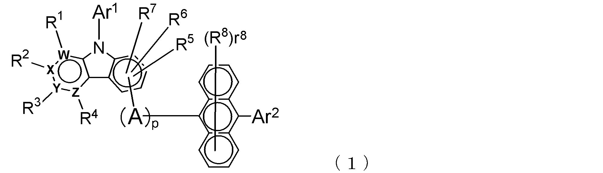

例えば、ピリドインドール環の一部を形成している原子W,X,Y及びZは、両者とも共通している。
また、一般式(1)におけるp及び2価の基Aは、一般式(2)におけるq及び2価の基Bに対応し、一般式(1)におけるAr1及びAr2は、一般式(2)におけるAr3、Ar4及びAr5に対応している。さらに、一般式(1)におけるR1~R8は、一般式(2)におけるR9~R16に対応し、一般式(1)のr8は、一般式(2)におけるr16に対応する。
以下、一般式(1)、(2)中の各基等について説明する。 As understood from the above general formula, the compound of general formula (1) and the compound of general formula (2) differ only in the bonding position of the anthracene ring to which the pyridoindole ring is linked, In this respect, both have substantially the same structure. That is, the compound of the general formula (1) has a pyridoindole ring linked to the 9th or 10th position of the anthracene ring, whereas the compound of the general formula (2) has a 9th and 10th position of the anthracene ring. It has a structure in which a pyridoindole ring is linked to a position other than the position.
For example, the atoms W, X, Y, and Z that form part of the pyridoindole ring are common to both.
In addition, p and divalent group A in general formula (1) correspond to q and divalent group B in general formula (2), and Ar 1 and Ar 2 in general formula (1) are represented by general formula ( This corresponds to Ar 3 , Ar 4 and Ar 5 in 2). Furthermore, R 1 to R 8 in the general formula (1) correspond to R 9 to R 16 in the general formula (2), and r 8 in the general formula (1) corresponds to r 16 in the general formula (2). To do.
Hereinafter, each group etc. in General formula (1), (2) are demonstrated.
上記の一般式(1)、(2)において、p及びqは、2価の基A及びBの数を示し、0~4の整数である。
即ち、これらの電子輸送性化合物は、2価の基A或いはBによってアントラセン環とピリドインドール環が結合された構造を有するが、p或いはqがゼロの場合には、2価の基A或いはBは存在せず、アントラセン環とピリドインドール環とは単結合により直接結合されたものとなっている。また、複数の2価の基A或いはBが連なってアントラセン環とピリドインドール環とを結合している場合(即ち、p或いはqが2以上のとき)、複数の基A或いはBは、互いに異なるものであってもよい。 (Divalent groups A, B and p, q)
In the above general formulas (1) and (2), p and q represent the number of divalent groups A and B, and are integers of 0 to 4.
That is, these electron transporting compounds have a structure in which an anthracene ring and a pyridoindole ring are bonded by a divalent group A or B. When p or q is zero, the divalent group A or B does not exist, and the anthracene ring and the pyridoindole ring are directly bonded by a single bond. Further, when a plurality of divalent groups A or B are linked to bond an anthracene ring and a pyridoindole ring (that is, when p or q is 2 or more), the plurality of groups A or B are It may be different.
例えば、上記の環基を形成する芳香族炭化水素環としては、ベンゼン環、ナフタレン環、アントラセン環、フェナントレン環、インデン環、ピレン環などを例示することができ、芳香族複素環としては、ピリジン環、ピリミジン環、キノリン環、イソキノリン環、ベンゾイミダゾール環、ピラゾール環、カルバゾール環、ナフチリジン環、フェナトリジン環、アクリジン環などを挙げることができる。 Such divalent groups A and B are aromatic hydrocarbon ring groups or aromatic heterocyclic groups, and these ring groups may have a monocyclic structure or a condensed polycyclic structure. You may have.
For example, examples of the aromatic hydrocarbon ring forming the above ring group include a benzene ring, a naphthalene ring, an anthracene ring, a phenanthrene ring, an indene ring, and a pyrene ring, and examples of the aromatic heterocyclic ring include pyridine And a ring, a pyrimidine ring, a quinoline ring, an isoquinoline ring, a benzimidazole ring, a pyrazole ring, a carbazole ring, a naphthyridine ring, a phenatridine ring, and an acridine ring.
上記置換基である芳香族炭化水素基の例としては、フェニル基、ビフェニリル基、ターフェニリル基、テトラキスフェニル基、スチリル基、ナフチル基、アントリル基、アセナフテニル基、フルオレニル基、フェナントリル基等を挙げることができる。
また、上記置換基における芳香族複素環基としては、インデニル基、ピレニル基、ピリジル基、ピリミジル基、フラニル基、ピロニル基、チエニル基、キノリル基、イソキノリル基、ベンゾフラニル基、ベンゾチエニル基、インドリル基、カルバゾリル基、ベンゾオキサゾリル基、ベンゾチアゾリル基、キノキサリル基、ベンゾイミダゾリル基、ピラゾリル基、ジベンゾフラニル基、ジベンゾチエニル基、ナフチリジニル基、フェナントロリニル基、アクリジニル基等を例示することができる。 In such a substituent, the alkyl group having 1 to 6 carbon atoms may be linear or branched, and specific examples thereof include a methyl group, an ethyl group, an n-propyl group, Examples thereof include isopropyl group, n-butyl group, isobutyl group, tert-butyl group, n-pentyl group, isopentyl group, neopentyl group, n-hexyl group and the like.
Examples of the aromatic hydrocarbon group as the substituent include a phenyl group, a biphenylyl group, a terphenylyl group, a tetrakisphenyl group, a styryl group, a naphthyl group, an anthryl group, an acenaphthenyl group, a fluorenyl group, and a phenanthryl group. it can.
As the aromatic heterocyclic group in the above substituent, an indenyl group, pyrenyl group, pyridyl group, pyrimidyl group, furanyl group, pyronyl group, thienyl group, quinolyl group, isoquinolyl group, benzofuranyl group, benzothienyl group, indolyl group Carbazolyl group, benzoxazolyl group, benzothiazolyl group, quinoxalyl group, benzoimidazolyl group, pyrazolyl group, dibenzofuranyl group, dibenzothienyl group, naphthyridinyl group, phenanthrolinyl group, acridinyl group and the like.
さらにキノン構造が形成されているものでもよく、例えば、フルオレノン環も2価の基A或いはBであってよい。 Moreover, said substituent may have a substituent further.
Further, a quinone structure may be formed. For example, the fluorenone ring may be a divalent group A or B.
一般式(1)におけるAr1及び一般式(2)におけるAr3は、芳香族炭化水素基もしくは芳香族複素環基(これらは一価の基である)を示し、これらの基は、何れも縮合多環構造を有していてもよい。
この芳香族炭化水素基としては、フェニル基、ビフェニリル基、ターフェニリル基、テトラキスフェニル基、スチリル基、ナフチル基、アントリル基、アセナフテニル基、フルオレニル基、フェナントリル基等を挙げることができる。
また、芳香族複素環基としては、インデニル基、ピレニル基、ピリジル基、ピリミジル基、フラニル基、ピロニル基、チエニル基、キノリル基、イソキノリル基、ベンゾフラニル基、ベンゾチエニル基、インドリル基、カルバゾリル基、ベンゾオキサゾリル基、ベンゾチアゾリル基、キノキサリル基、ベンゾイミダゾリル基、ピラゾリル基、ジベンゾフラニル基、ジベンゾチエニル基、ナフチリジニル基、フェナントロリニル基、アクリジニル基等を挙げることができる。 (Ar 1 and Ar 3 )
Ar 1 in the general formula (1) and Ar 3 in the general formula (2) represent an aromatic hydrocarbon group or an aromatic heterocyclic group (these are monovalent groups), and these groups are all It may have a condensed polycyclic structure.
Examples of the aromatic hydrocarbon group include a phenyl group, a biphenylyl group, a terphenylyl group, a tetrakisphenyl group, a styryl group, a naphthyl group, an anthryl group, an acenaphthenyl group, a fluorenyl group, and a phenanthryl group.
Examples of the aromatic heterocyclic group include indenyl group, pyrenyl group, pyridyl group, pyrimidyl group, furanyl group, pyronyl group, thienyl group, quinolyl group, isoquinolyl group, benzofuranyl group, benzothienyl group, indolyl group, carbazolyl group, A benzoxazolyl group, a benzothiazolyl group, a quinoxalyl group, a benzimidazolyl group, a pyrazolyl group, a dibenzofuranyl group, a dibenzothienyl group, a naphthyridinyl group, a phenanthrolinyl group, an acridinyl group, and the like can be given.
一般式(1)中のAr2及び一般式(2)中のAr4,Ar5は、芳香族炭化水素基を示し、この芳香族炭化水素基も縮合多環構造を有していてよい。
このような芳香族炭化水素基は、上記Ar1及びAr3に関して例示したものと同様の基、例えば、フェニル基、ビフェニリル基、ターフェニリル基、テトラキスフェニル基、スチリル基、ナフチル基、アントリル基、アセナフテニル基、フルオレニル基、フェナントリル基等を挙げることができる。
さらに、これらの芳香族炭化水素基も、上記のAr1及びAr3に関して例示したものと同様の置換基を有していてもよく、かかる置換基もさらに置換基を有していてもよい。 (Ar 2 and Ar 4 , Ar 5 )
Ar 2 in the general formula (1) and Ar 4 and Ar 5 in the general formula (2) each represent an aromatic hydrocarbon group, and this aromatic hydrocarbon group may also have a condensed polycyclic structure.
Such aromatic hydrocarbon groups are the same as those exemplified for Ar 1 and Ar 3 above, for example, phenyl group, biphenylyl group, terphenylyl group, tetrakisphenyl group, styryl group, naphthyl group, anthryl group, acenaphthenyl group. Group, fluorenyl group, phenanthryl group and the like.
Furthermore, these aromatic hydrocarbon groups may also have the same substituents as those exemplified for Ar 1 and Ar 3 above, and these substituents may further have a substituent.
一般式(1)において、R1~R7は、それぞれ、水素原子、重水素原子、フッ素原子、塩素原子、シアノ基、トリフルオロメチル基、炭素原子数1ないし6の無置換アルキル基、無置換または置換芳香族炭化水素基もしくは芳香族複素環基を表す。また、一般式(2)におけるR9~R15も、これらR1~R7と同じである。
上記の炭素原子数1ないし6の無置換アルキル基は、前述した2価の基Aが有していてよい置換基として挙げたアルキル基と同様のものである。
また、上記の芳香族炭化水素基及び芳香族複素環基は、上記のAr1に関して示したものと同様の基であり、これらの基が有していてよい置換基も、Ar1に関して示したものと同様である。 (R 1 to R 7 and R 9 to R 15 )
In the general formula (1), R 1 to R 7 are each a hydrogen atom, deuterium atom, fluorine atom, chlorine atom, cyano group, trifluoromethyl group, unsubstituted alkyl group having 1 to 6 carbon atoms, A substituted or substituted aromatic hydrocarbon group or an aromatic heterocyclic group is represented. In addition, R 9 to R 15 in the general formula (2) are the same as R 1 to R 7 .
The unsubstituted alkyl group having 1 to 6 carbon atoms is the same as the alkyl group mentioned as the substituent that the divalent group A may have.
In addition, the aromatic hydrocarbon group and the aromatic heterocyclic group are the same groups as those described above with respect to Ar 1 , and the substituents that these groups may have have also been described with respect to Ar 1 . It is the same as that.
一般式(1)中のr8はアントラセン環に結合し得るR8の数を示し、0~8の整数を表す。同様に、一般式(2)中のr16はR16のアントラセン環に結合し得るR8の数を示し、0~7の整数を表す。
また、R8及びR16は、重水素原子、フッ素原子、塩素原子、シアノ基、トリフルオロメチル基、または炭素原子数1ないし6の無置換アルキル基を表し、さらに、r8及びr16が2以上の数であるとき複数のR8及びR16は互いに同一でも異なってもよい。
上記の無置換アルキル基も、前述した2価の基A、Bが有していてよい置換基として挙げたアルキル基と同様のものである。 (R 8 , r 8 and R 16 , r 16 )
R 8 of the general formula (1) represents the number of R 8 capable of binding to the anthracene ring, it represents an integer of 0-8. Similarly, r 16 in the general formula (2) represents the number of R 8 that can be bonded to the anthracene ring of R 16 and represents an integer of 0 to 7.
R 8 and R 16 represent a deuterium atom, a fluorine atom, a chlorine atom, a cyano group, a trifluoromethyl group, or an unsubstituted alkyl group having 1 to 6 carbon atoms, and r 8 and r 16 are When the number is 2 or more, the plurality of R 8 and R 16 may be the same as or different from each other.
The unsubstituted alkyl group is the same as the alkyl group mentioned as the substituent that the above-described divalent groups A and B may have.
ピリドインドール環の一部を形成している原子W,X,Y及びZは、一般式(1)及び一般式(2)の何れの場合においても、これらの何れか一つのみが窒素原子であり、他は炭素原子である。一般的には、これに限定されるものではないが、Yが炭素原子であり、W,X及びZが窒素原子となる。
また、この環を構成する炭素原子には、基R1~R4(水素原子を含む)の何れかが結合しているが、窒素原子には、基R1~R4は結合しておらず、水素原子も結合していない。 (W to Z)
The atoms W, X, Y, and Z that form part of the pyridoindole ring are the nitrogen atoms in any one of the general formulas (1) and (2). And the others are carbon atoms. In general, but not limited to this, Y is a carbon atom, and W, X, and Z are nitrogen atoms.
In addition, any of the groups R 1 to R 4 (including a hydrogen atom) is bonded to the carbon atom constituting the ring, but the groups R 1 to R 4 are not bonded to the nitrogen atom. Neither hydrogen atom is bonded.
本発明において、上記一般式(1)で表される電子輸送性化合物においては、例えば下記式(1a)で示されている位置に、アントラセン環がピリドインドール環に結合する位置が固定されていることが好ましい。 A suitable electron transporting compound of the general formula (1);
In the present invention, in the electron transporting compound represented by the general formula (1), for example, the position where the anthracene ring is bonded to the pyridoindole ring is fixed at the position represented by the following formula (1a). Preferably it is.


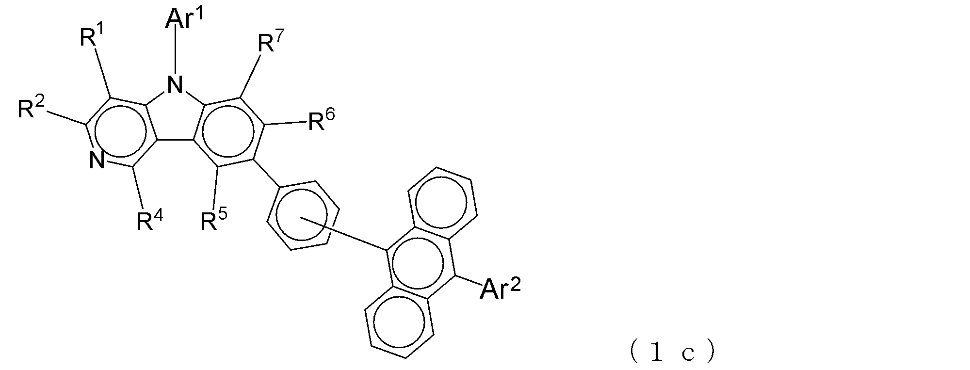


上述した一般式(1)で表される電子輸送性化合物の具体例としては、これに限定されるものではないが、以下のものを例示することができる。 Specific examples of the electron transporting compound of the general formula (1);
Specific examples of the electron transporting compound represented by the general formula (1) described above are not limited thereto, but the following can be exemplified.
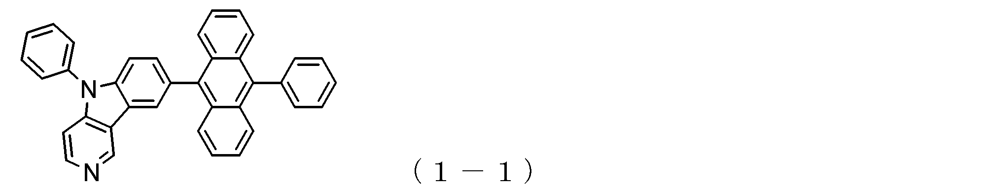

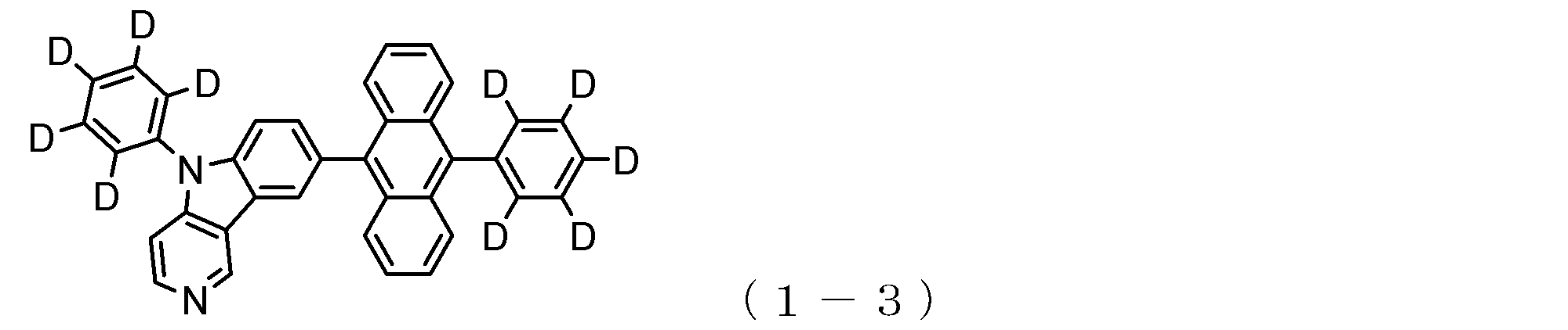
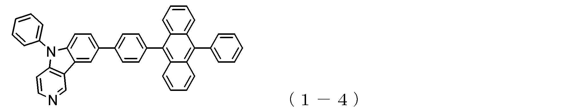


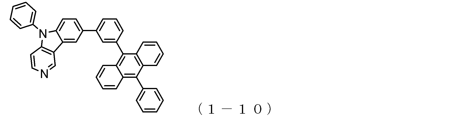


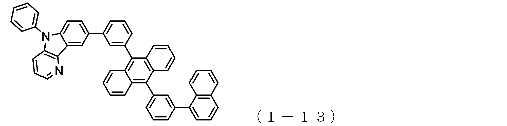


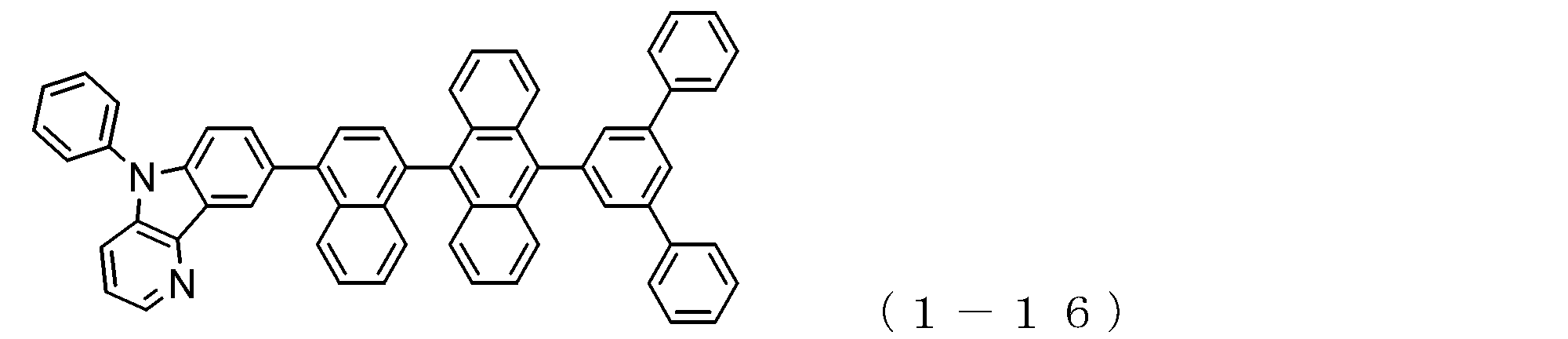

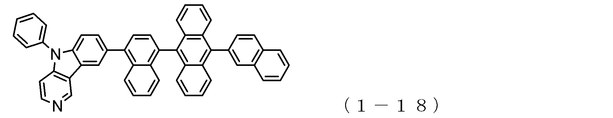


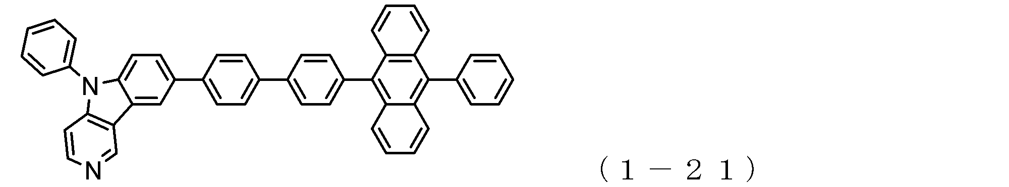
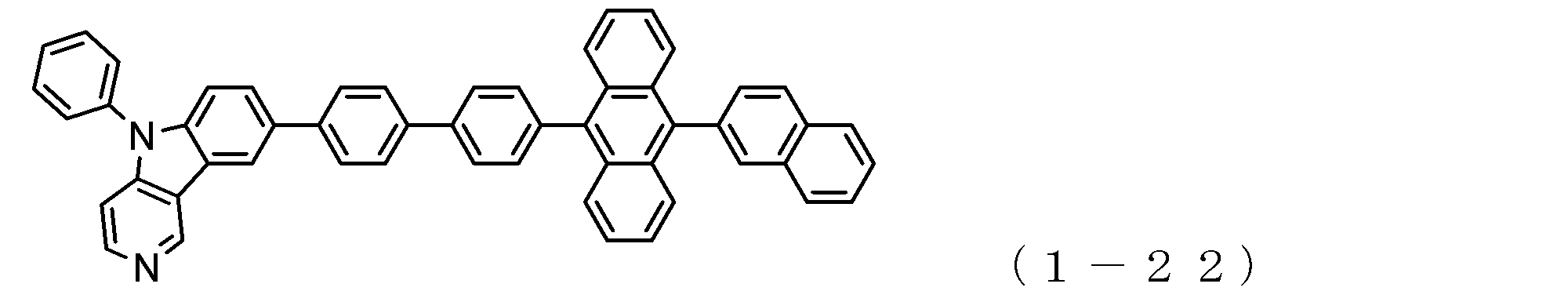


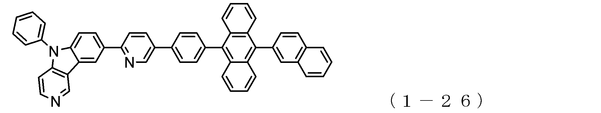


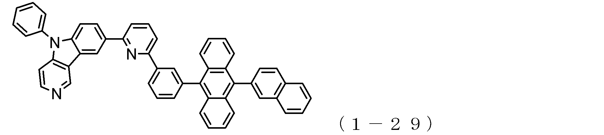
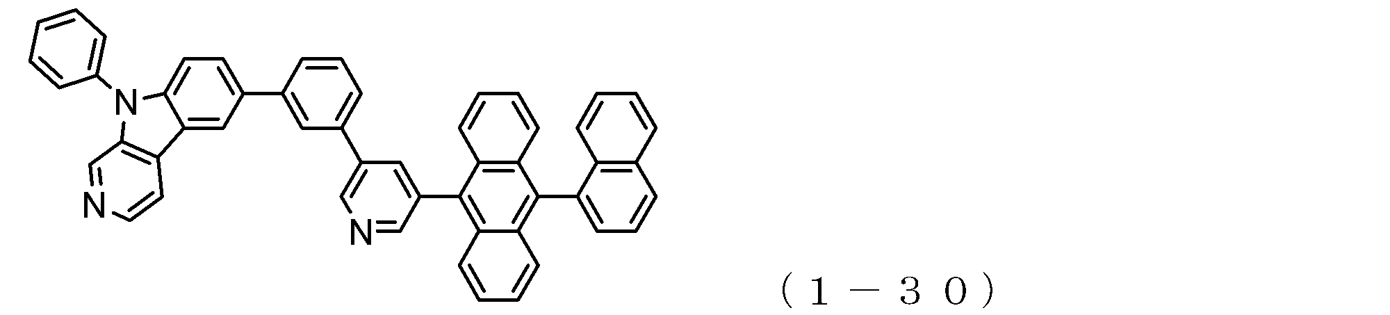
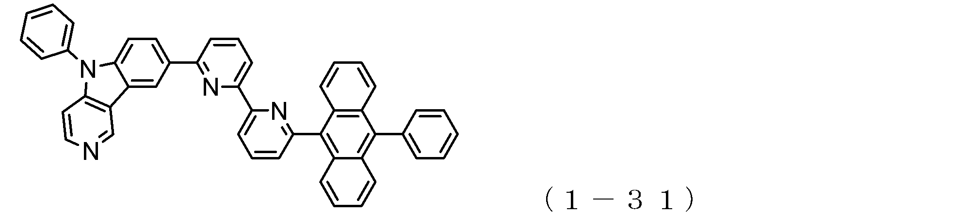
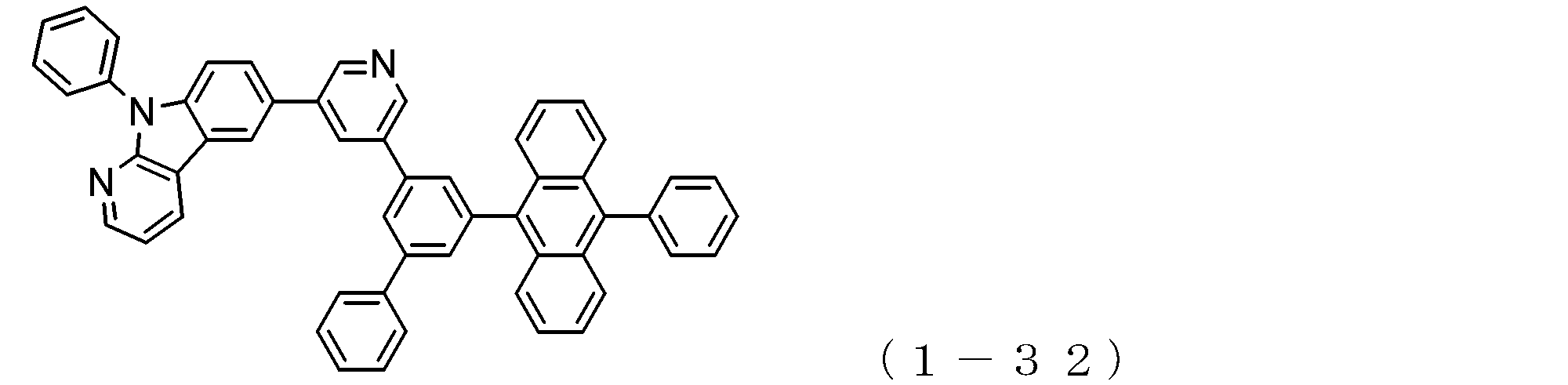


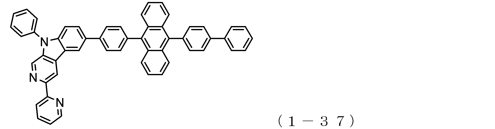

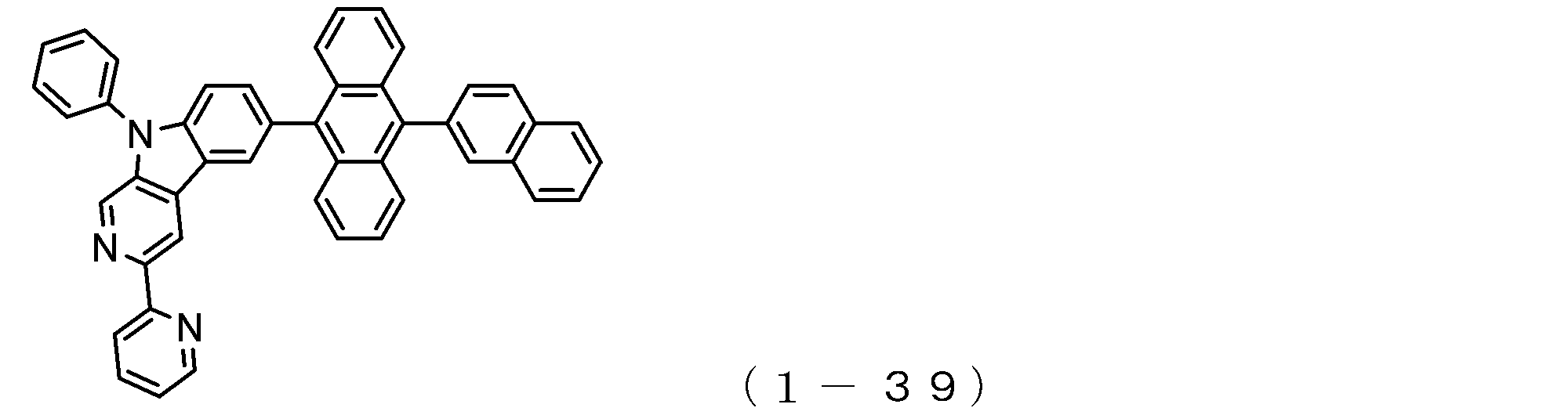
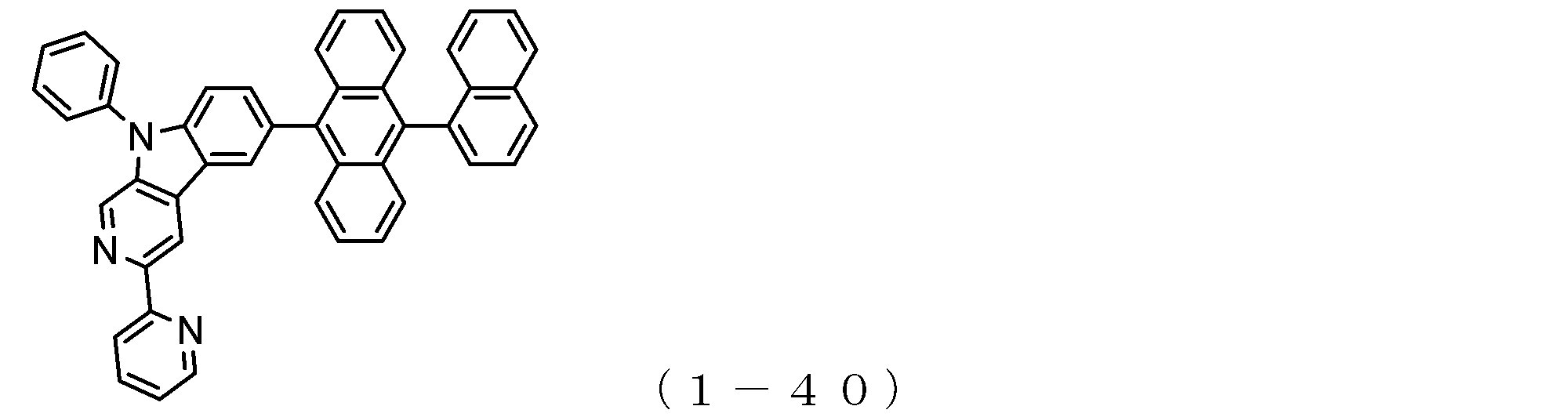
本発明において、前述した一般式(2)で表される電子輸送性化合物においては、例えば下記式(2a)で示されているように、アントラセン環の2位にピリドインドール環が結合していることが好ましく、さらに、下記式(2b)で示されている位置に、アントラセン環がピリドインドール環に結合する位置が固定されていることが好ましい。
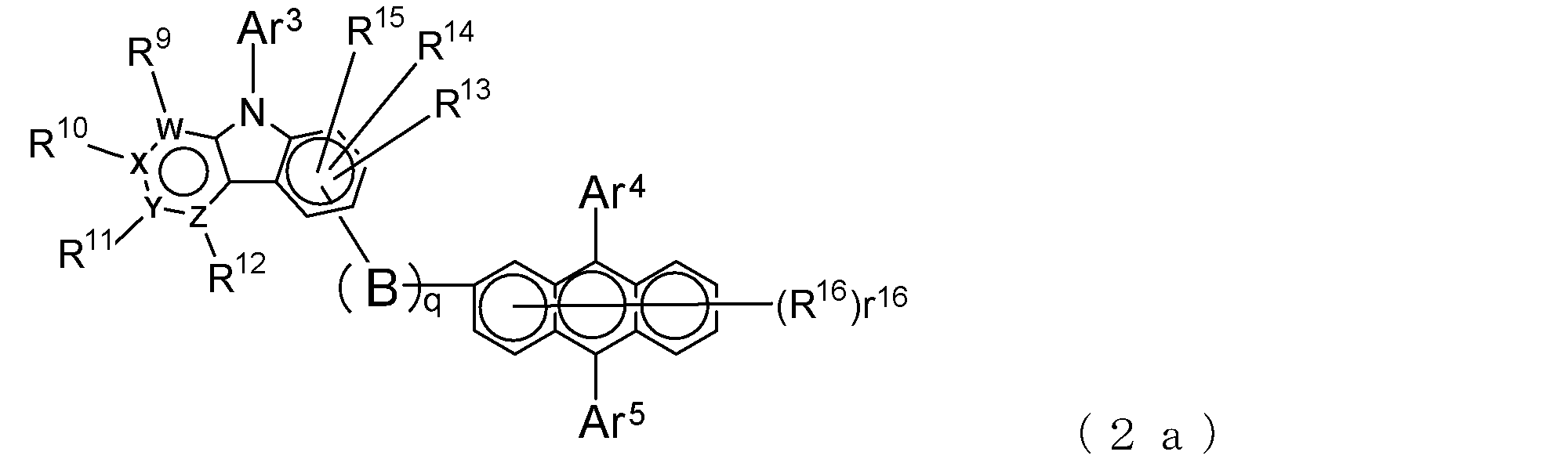

In the present invention, in the electron transporting compound represented by the general formula (2) described above, a pyridoindole ring is bonded to the 2-position of the anthracene ring, for example, as shown in the following formula (2a). Further, it is preferable that the position where the anthracene ring is bonded to the pyridoindole ring is fixed at the position represented by the following formula (2b).
このような構造を有する好適な電子輸送性化合物は、例えば下記一般式(2c)~(2e)で表される。 Also in such an electron transporting compound, it is preferable that Y is a nitrogen atom among the ring constituent atoms W to Z, and the anthracene ring and the pyridoindole ring are connected by a single bond. (Q = 0) or a structure linked by a phenylene group (q = 1) is preferable, and r 16 = 0 is more preferable.
Suitable electron transporting compounds having such a structure are represented, for example, by the following general formulas (2c) to (2e).
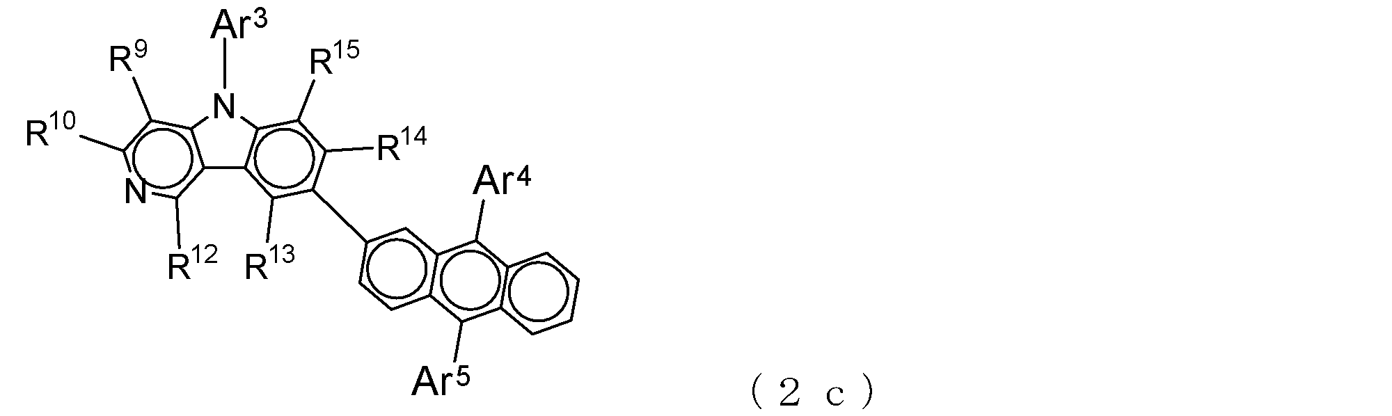


上述した一般式(2)で表される電子輸送性化合物の具体例としては、これに限定されるものではないが、以下のものを例示することができる。 Specific examples of the electron transporting compound of the general formula (2);
Specific examples of the electron transporting compound represented by the general formula (2) described above are not limited thereto, but the following can be exemplified.
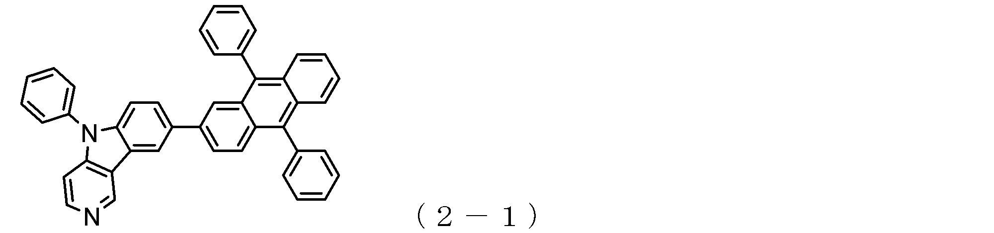


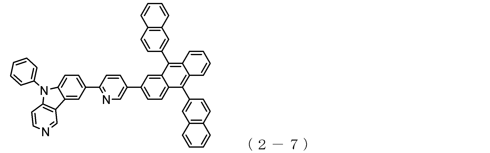
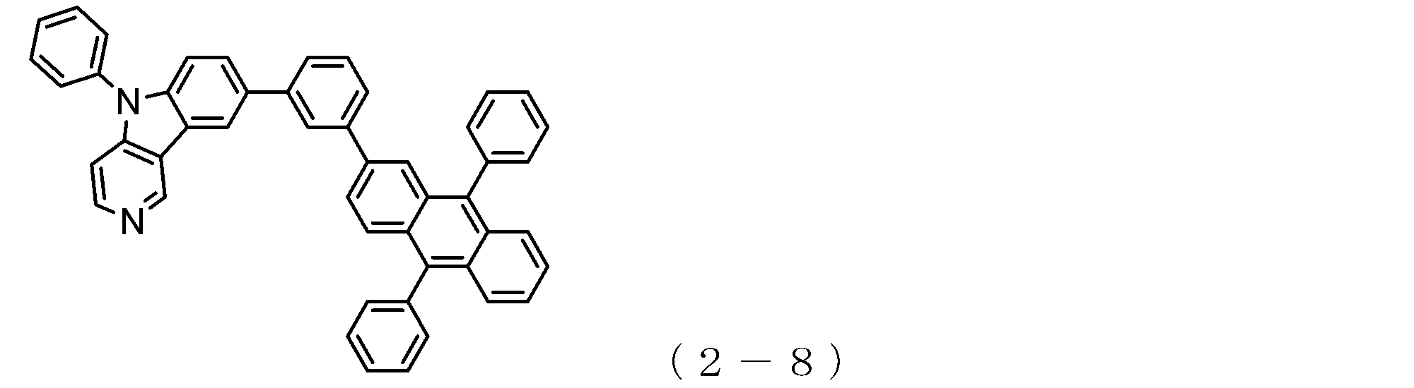


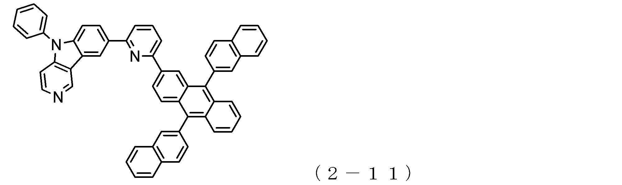
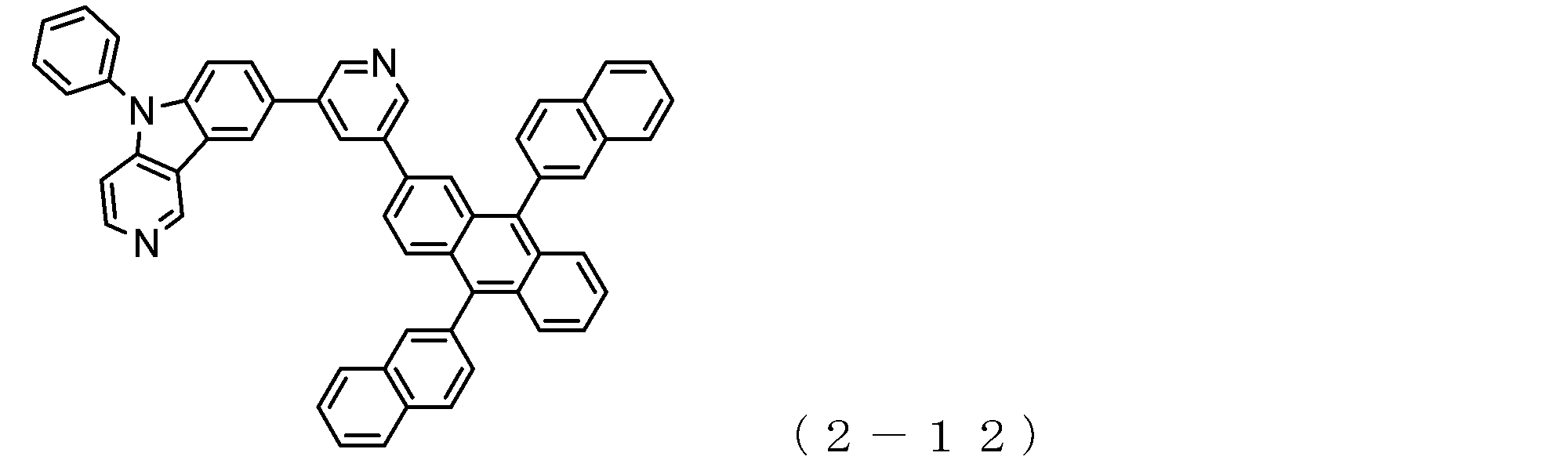
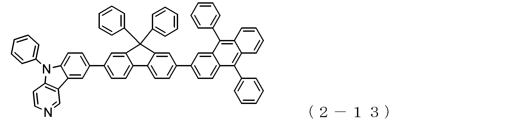
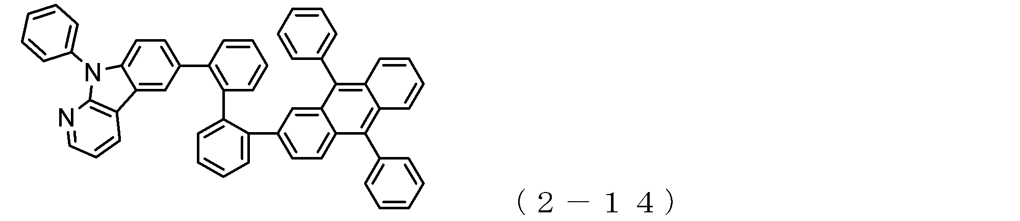
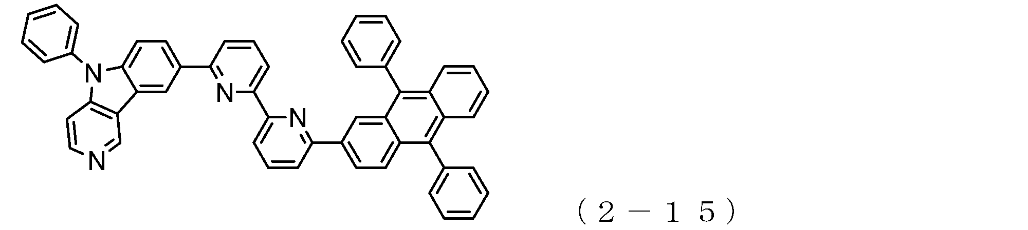


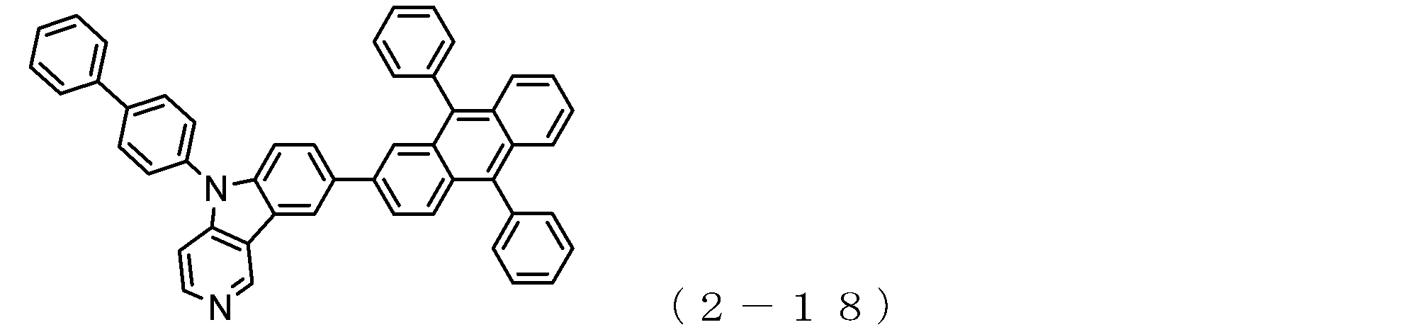
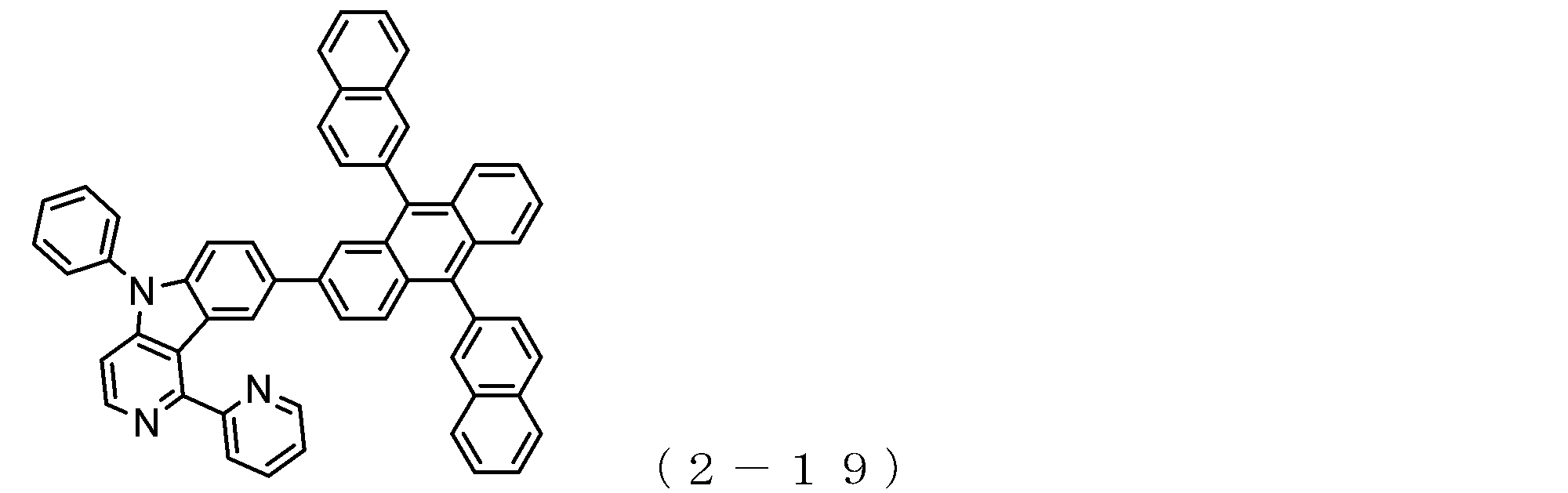

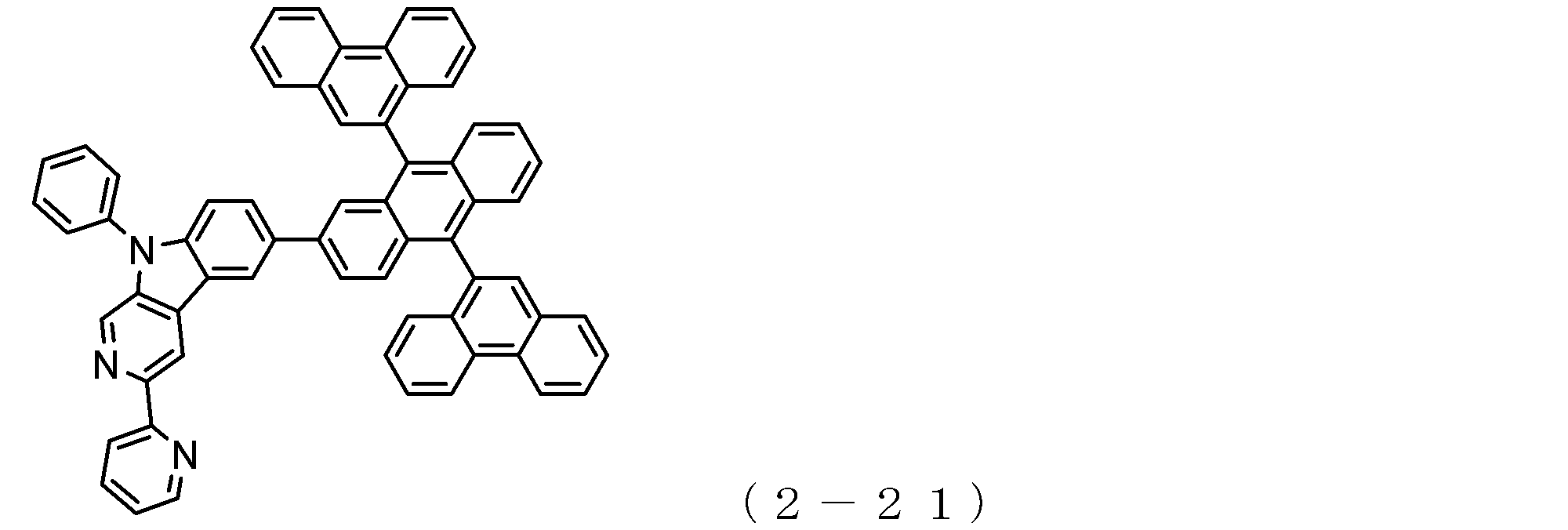

上述した一般式(1)或いは(2)で表される電子輸送性化合物は、新規な化合物であり、これらの化合物は例えば、以下のように合成できる。
まず、相当するハロゲノアニリノピリジンをパラジウム触媒による環化反応を行うことによって相当するピリドインドール誘導体を合成し(例えば、J.Chem.Soc.,Perkin Trans.1,1505(1999)参照)、さらに、種々の芳香族炭化水素化合物もしくは芳香族複素環化合物のハライドとのUllmann反応やBuchwald-Hartwig反応などの縮合反応を行うことによって、相当する5位にアリール基(Ar1、Ar3)が導入されたピリドインドール誘導体を合成することができる。
このようにして合成されたピリドインドール誘導体を、N-ブロモスクシンイミドなど用いてブロモ化し、相当するブロモ体を合成することができる。
このようなピリドインドール誘導体のブロモ体と、既知の方法によって合成したアントラセン環構造を有するボロン酸またはボロン酸エステル(例えば、J.Org.Chem.,60,7508(1995)参照)を、Suzukiカップリングなどのクロスカップリング反応を行うことによって(例えば、非特許文献5参照)、アントラセン環骨格とピリドインドール環骨格とを有する前述した電子輸送性化合物を合成することができる。
また、上記ピリドインドール誘導体のブロモ体から対応するボロン酸またはボロン酸エステルを合成し、これに芳香族炭化水素もしくは芳香族複素環のジハロゲン化物を反応させることによって、ハロゲン化アリール基が結合したピリドインドール誘導体とした後に、上記アントラセン環構造を有するボロン酸またはボロン酸エステルを、Suzukiカップリングなどのクロスカップリング反応を行うことによっても、アントラセン環骨格とピリドインドール環骨格とを有する前述した電子輸送性化合物を合成することができる。 (Production of electron transporting compounds)
The electron transporting compound represented by the general formula (1) or (2) described above is a novel compound, and these compounds can be synthesized, for example, as follows.
First, a corresponding pyridoindole derivative is synthesized by subjecting a corresponding halogenoanilinopyridine to a palladium-catalyzed cyclization reaction (see, for example, J. Chem. Soc., Perkin Trans. 1, 1505 (1999)). Furthermore, an aryl group (Ar 1 , Ar 3 ) is present at the corresponding 5-position by performing a condensation reaction such as an Ullmann reaction or Buchwald-Hartwig reaction with various aromatic hydrocarbon compounds or halides of aromatic heterocyclic compounds. The introduced pyridoindole derivative can be synthesized.
The pyridoindole derivative thus synthesized can be brominated using N-bromosuccinimide or the like to synthesize the corresponding bromo compound.
A bromo compound of such a pyridoindole derivative and a boronic acid or boronic acid ester having an anthracene ring structure synthesized by a known method (see, for example, J. Org. Chem., 60, 7508 (1995)) By performing a cross-coupling reaction such as coupling (for example, see Non-Patent Document 5), the above-described electron transporting compound having an anthracene ring skeleton and a pyridoindole ring skeleton can be synthesized.
In addition, by synthesizing a corresponding boronic acid or boronic acid ester from the bromo form of the above pyridoindole derivative, and reacting this with a dihalide of an aromatic hydrocarbon or an aromatic heterocyclic ring, a halogenated aryl group was bonded. The aforementioned anthracene ring skeleton and pyridoindole ring skeleton can also be obtained by performing a cross-coupling reaction such as Suzuki coupling on the boronic acid or boronic acid ester having the anthracene ring structure after the pyridoindole derivative is obtained. The electron transporting compound can be synthesized.
本発明においては、3個以上のトリフェニルアミン骨格が単結合または2価の炭化水素基(即ち、ヘテロ原子を含まない2価の基)で結合されている分子構造を有するアリールアミン化合物(α)を用いて正孔注入層を形成する。このアリールアミン化合物(α)は、後述するアリールアミン化合物(β)と比較しても正孔移動度が高い。 <Arylamine compound (α)>
In the present invention, an arylamine compound having a molecular structure in which three or more triphenylamine skeletons are bonded by a single bond or a divalent hydrocarbon group (that is, a divalent group not containing a hetero atom) (α ) To form a hole injection layer. This arylamine compound (α) has a higher hole mobility than the arylamine compound (β) described later.

前記一般式(3)において、r17~r28は、それぞれ分子中の各ベンゼン環に結合し得る基R17~R28の数を示すものであり、これらの内、r17、r18、r21、r24、r27及びr28は、0~5の整数を表す。また、r19、r20、r22、r23、r25及びr26は、0~4の整数を表す。即ち、r17~r28の値が0であることは、当該ベンゼン環には基R17~R28が結合していないことを意味する。 (R 17 to R 28 and r 17 to r 28 )
In the general formula (3), r 17 to r 28 indicate the number of groups R 17 to R 28 that can be bonded to each benzene ring in the molecule, and of these, r 17 , r 18 , r 21 , r 24 , r 27 and r 28 each represents an integer of 0 to 5. R 19 , r 20 , r 22 , r 23 , r 25 and r 26 each represents an integer of 0 to 4. That is, a value of r 17 to r 28 of 0 means that the groups R 17 to R 28 are not bonded to the benzene ring.
また、一般式(3)において、E1~E3は、トリフェニルアミン骨格同士の結合部分に相当するものであり、単結合或いは2価の炭化水素基を示す。
この2価の炭化水素基、即ち、ヘテロ原子を含まない2価の基としては、下記式;

In the general formula (3), E 1 to E 3 correspond to the bonding portion between the triphenylamine skeletons and represent a single bond or a divalent hydrocarbon group.
Examples of the divalent hydrocarbon group, that is, a divalent group not containing a hetero atom include the following formula:
また、R29、R30及びR31は、それぞれ、前記R17~R28と同様の原子もしくは基を示すものである。 Incidentally, in the formula which represents a bivalent radical of the, n1 represents an integer of 1 ~ 3, r 29, r 30, r 31 indicating the number of R 29, R 30 and R 31 are each, 0 ~ Represents an integer of 4.
R 29 , R 30 and R 31 each represent the same atom or group as R 17 to R 28 .
上述した一般式(3)で表されるアリールアミン化合物(α)の具体例としては、これに限定されるものではないが、以下の(3-1)~(3-23)の化合物を挙げることができるが、これらの中でも、上述した一般式(3)で表されるトリアリールアミン(トリフェニルアミン骨格を4個有するもの)が特に好ましい。 Specific examples of the arylamine compound (α) of the general formula (3);
Specific examples of the arylamine compound (α) represented by the general formula (3) described above include, but are not limited to, the following compounds (3-1) to (3-23): Among these, the triarylamine (having four triphenylamine skeletons) represented by the general formula (3) described above is particularly preferable.


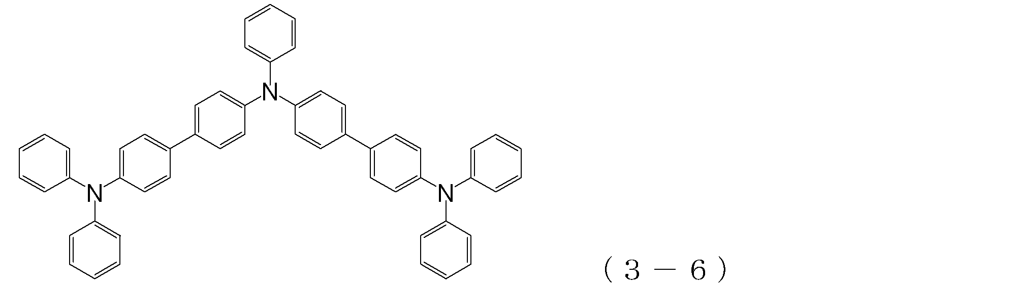


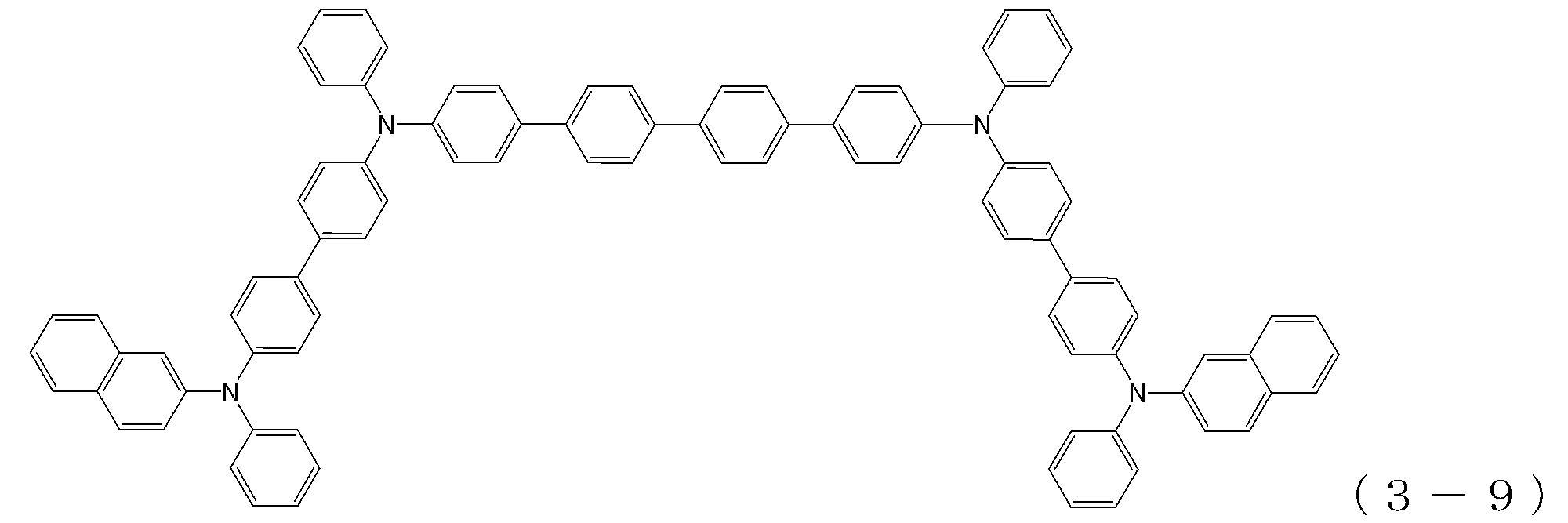

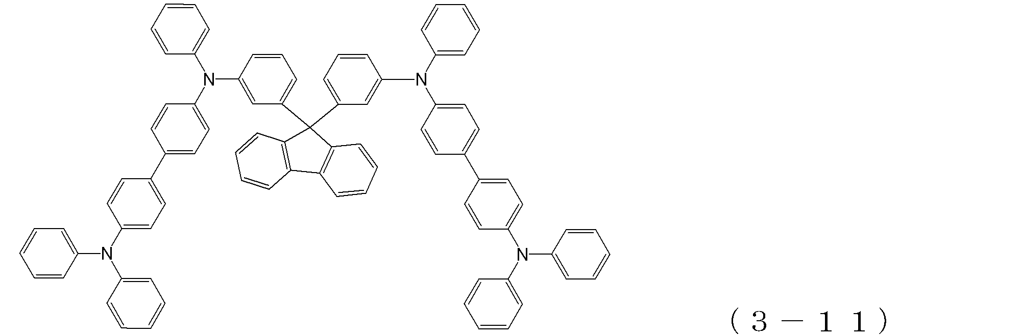
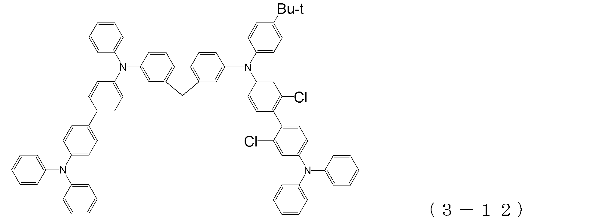
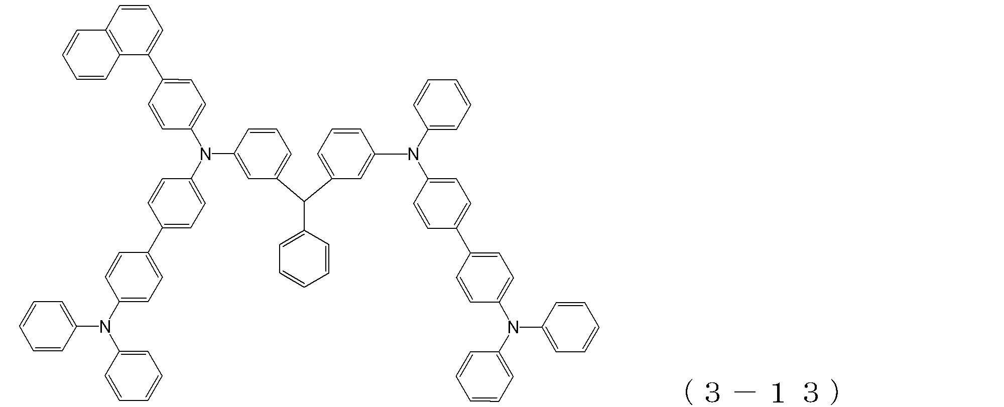

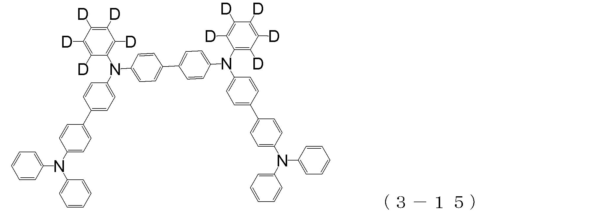


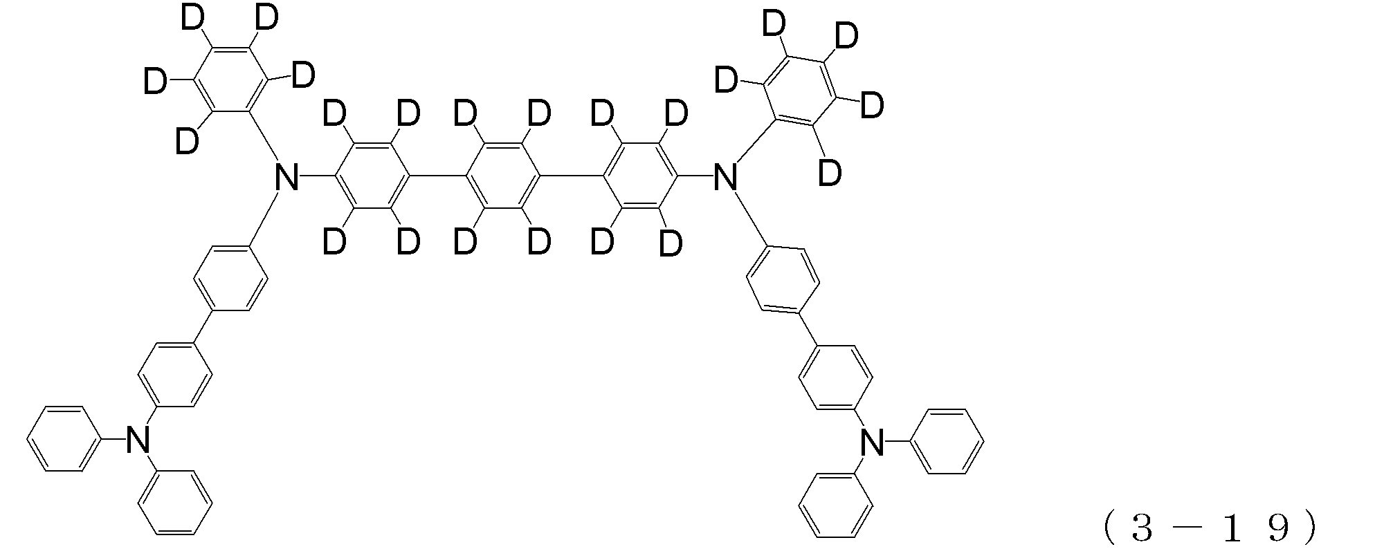
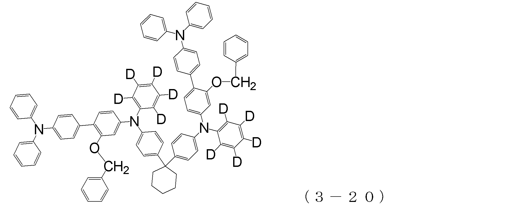
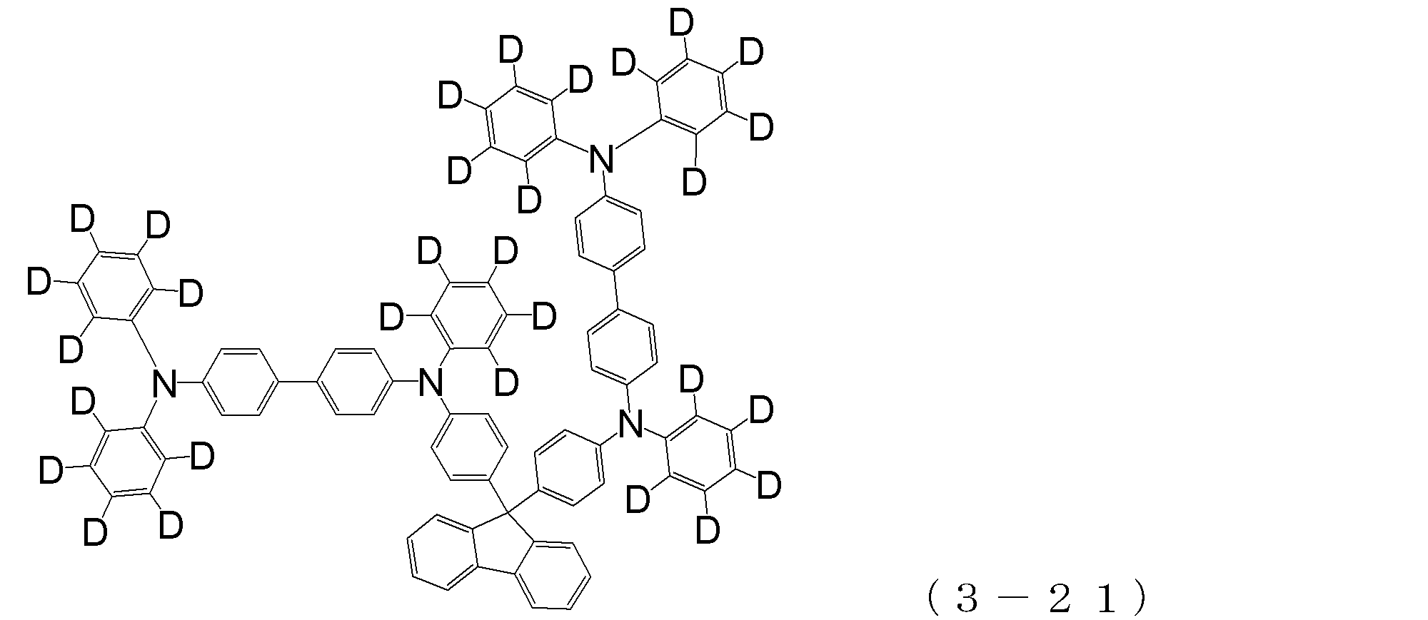
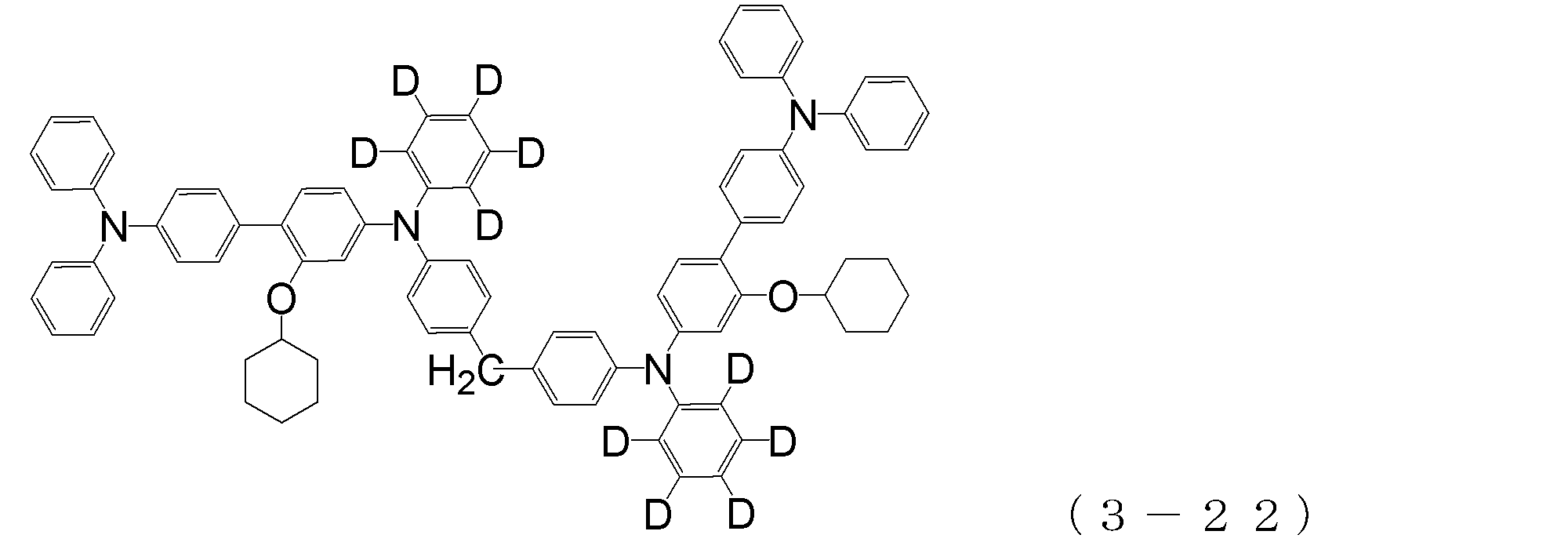
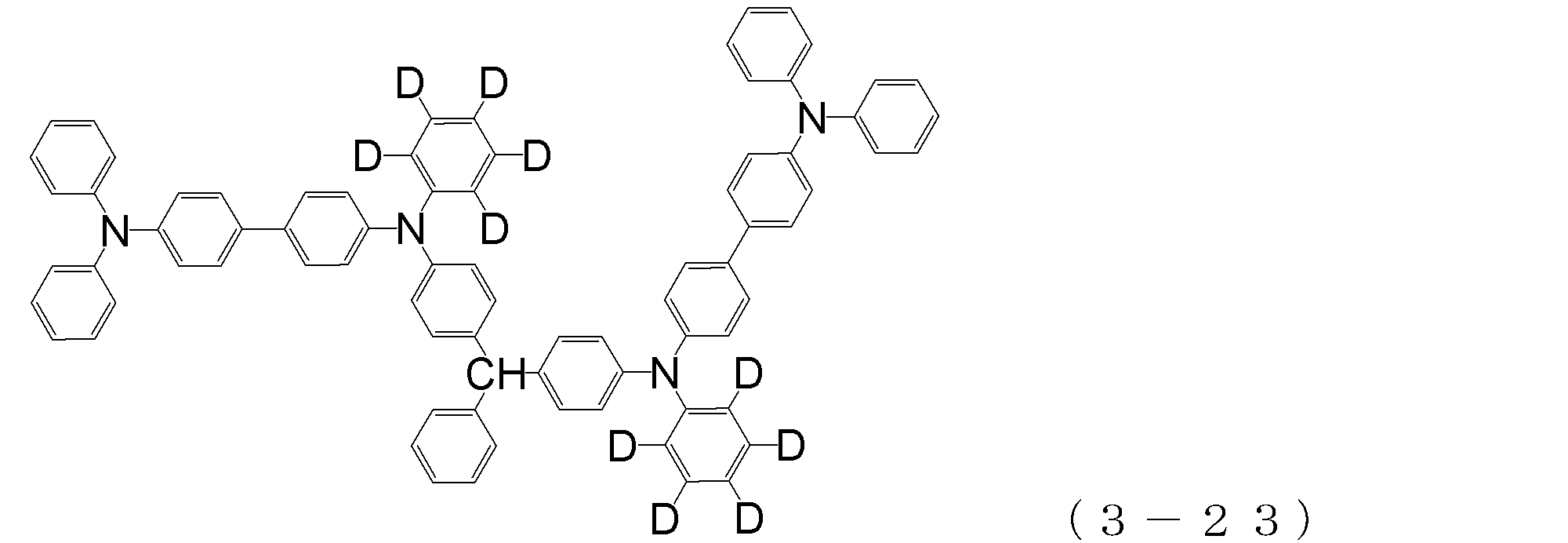
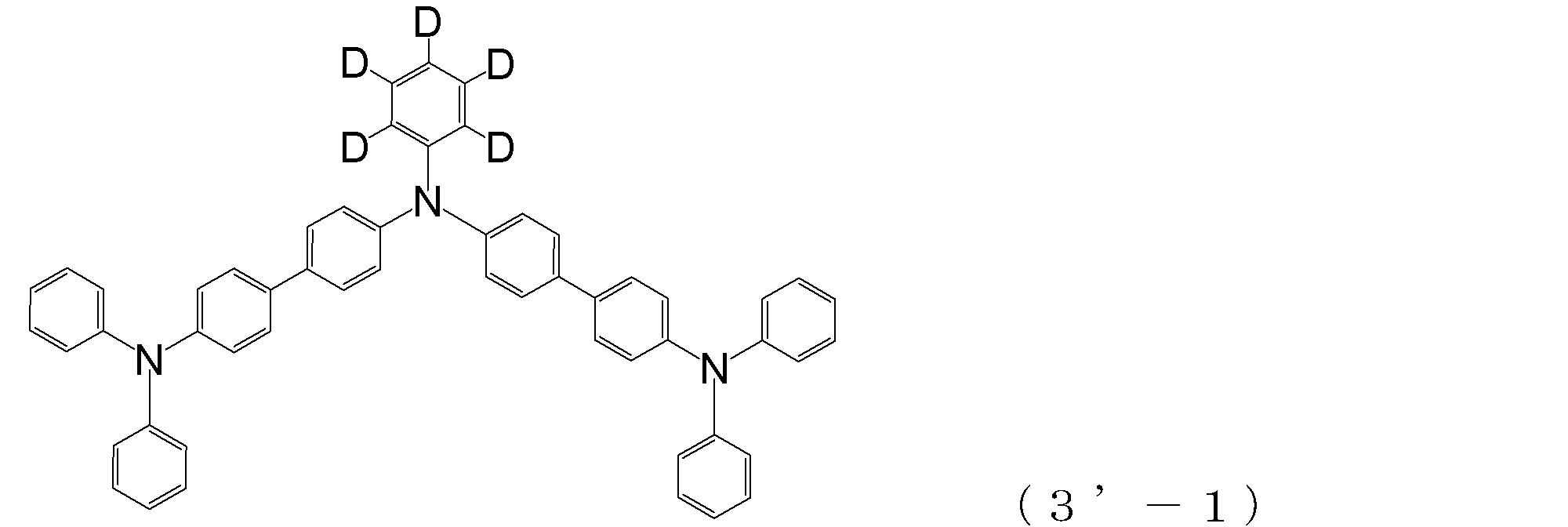
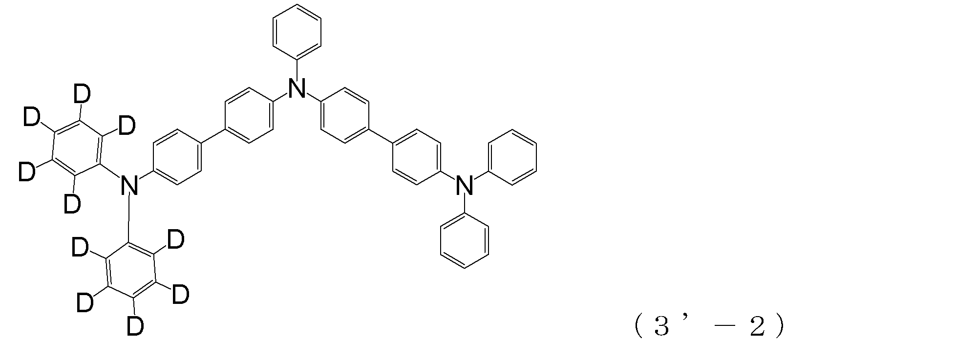


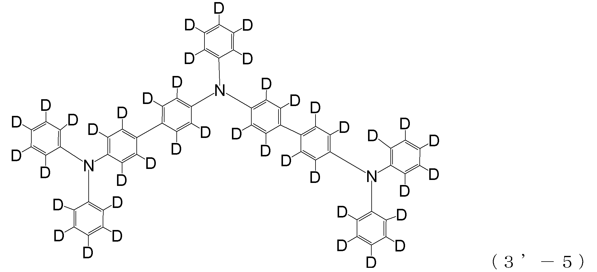

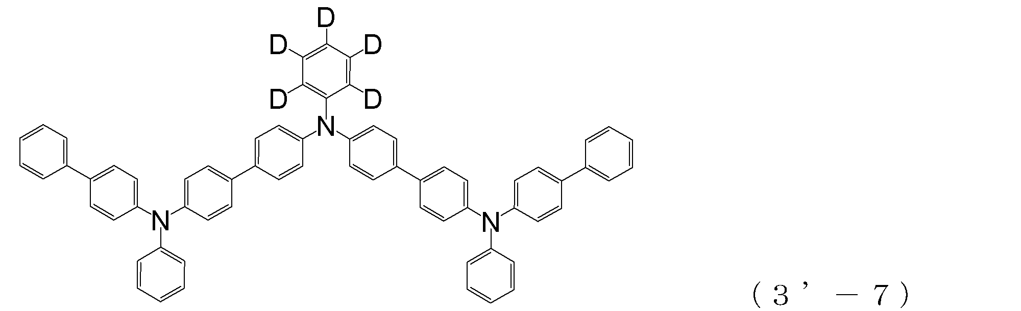
本発明においては、正孔輸送層を形成する化合物として、2個のトリフェニルアミン骨格が単結合または2価の炭化水素基(即ち、ヘテロ原子を含まない2価の基)で結合されている分子構造を有するアリールアミン化合物(β)が使用される。
このようなアリールアミン化合物(β)は、例えば下記の一般式(4)で表わされる。
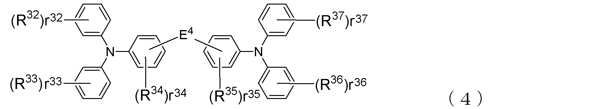
In the present invention, two triphenylamine skeletons are bonded by a single bond or a divalent hydrocarbon group (that is, a divalent group not containing a hetero atom) as a compound that forms a hole transport layer. An arylamine compound (β) having a molecular structure is used.
Such an arylamine compound (β) is represented, for example, by the following general formula (4).
上記一般式(4)において、r32~r37は、分子中のベンゼン環に結合し得る基R32~R37の数を示すものであり、r32、r33、r36、r37は、0~5の整数であり、r34、r35は、0~4の整数を表す。即ち、r32~r37の値が0であるときは、当該ベンゼン環には基R32~R37が結合していないことを意味する。 (R 32 to R 37 and r 32 to r 37 )
In the general formula (4), r 32 to r 37 indicate the number of groups R 32 to R 37 that can be bonded to the benzene ring in the molecule, and r 32 , r 33 , r 36 , and r 37 are , 0 to 5 and r 34 and r 35 each represents an integer of 0 to 4. That is, when the values of r 32 to r 37 are 0, it means that the groups R 32 to R 37 are not bonded to the benzene ring.
芳香族炭化水素基または芳香族複素環基の具体例としては、R17~R28の場合と同様な基をあげることができる。 In the above R 32 to R 37 , the unsubstituted alkyl group having 1 to 6 carbon atoms or the unsubstituted alkenyl group having 2 to 6 carbon atoms may be linear or branched. Examples thereof include the same alkyl group and alkenyl group as those exemplified for R 17 to R 28 in (3).
Specific examples of the aromatic hydrocarbon group or aromatic heterocyclic group include the same groups as in R 17 to R 28 .
また、一般式(4)において、E4は、前述した一般式(3)中のE1~E3と同じであり、単結合或いは2価の炭化水素基を示す。
この2価の炭化水素基は、先のE1~E3について述べたとおり、下記式;

In the general formula (4), E 4 are the same as E 1 ~ E 3 in the general formula (3) described above, a single bond or a divalent hydrocarbon group.
This divalent hydrocarbon group has the following formula as described for E 1 to E 3 above:
上述した一般式(4)で表されるアリールアミン化合物(β)の具体例としては、これに限定されるものではないが、例えば、以下の(4-1)~(4-23)の化合物を挙げることができる。 Specific examples of the arylamine compound (β) of the general formula (4);
Specific examples of the arylamine compound (β) represented by the general formula (4) described above are not limited thereto, but examples thereof include the following compounds (4-1) to (4-23): Can be mentioned.

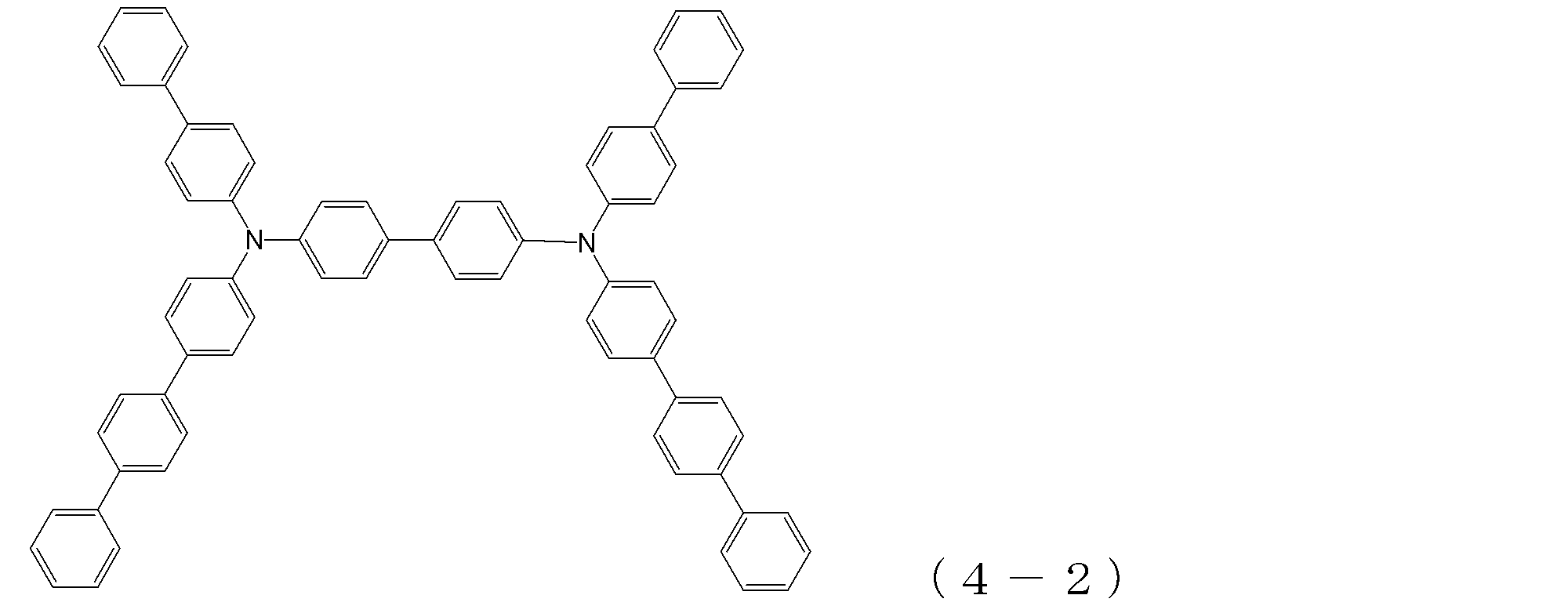
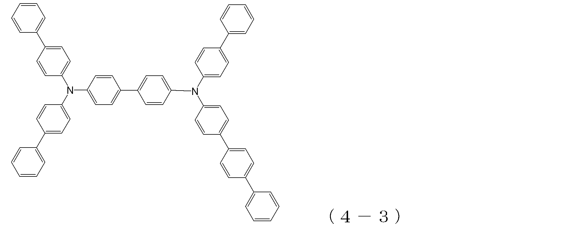
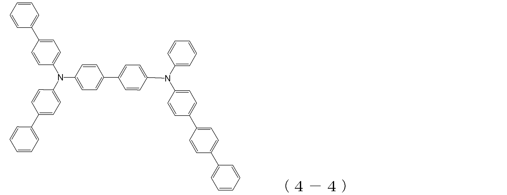
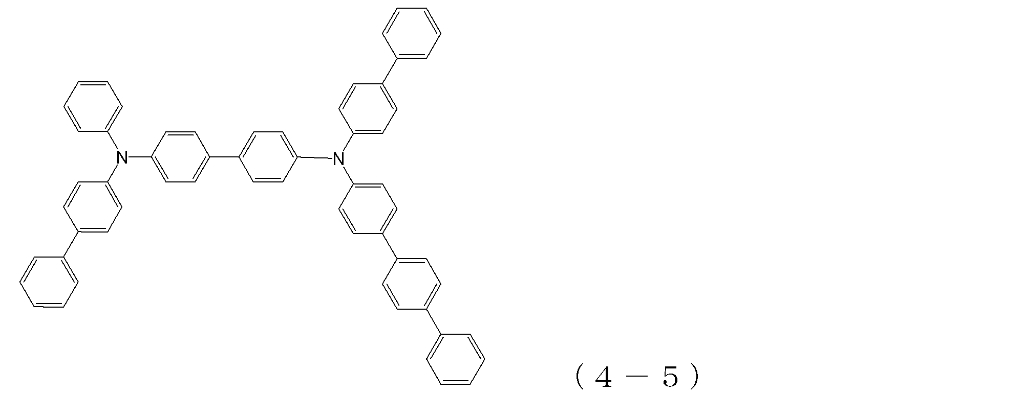
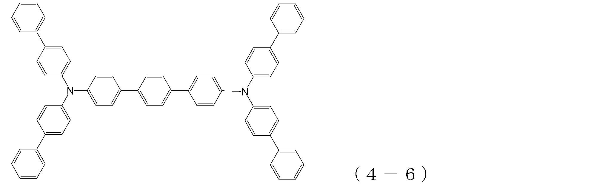
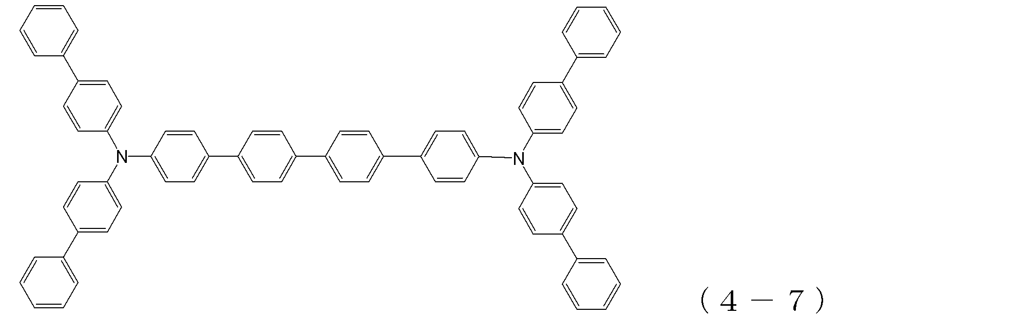
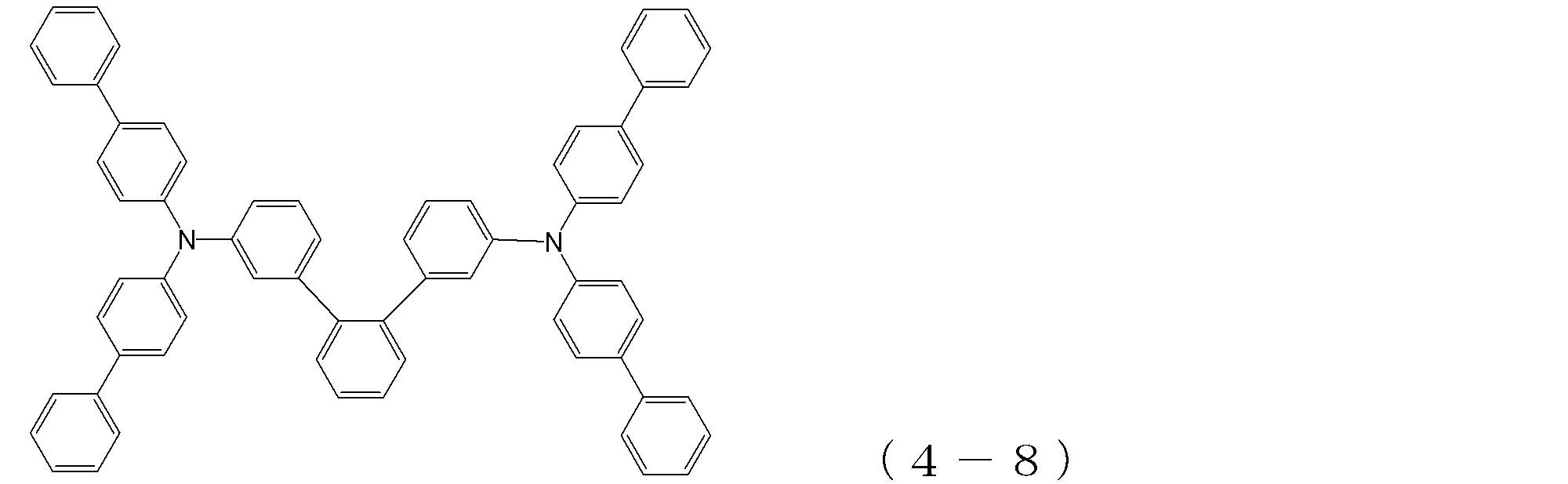

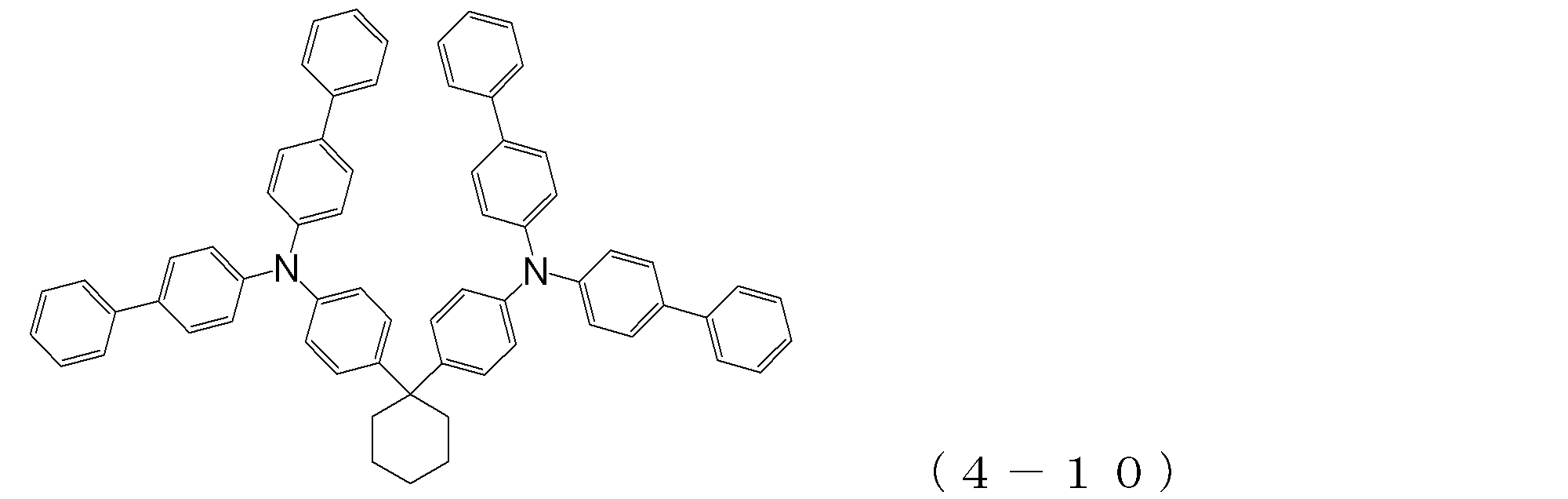


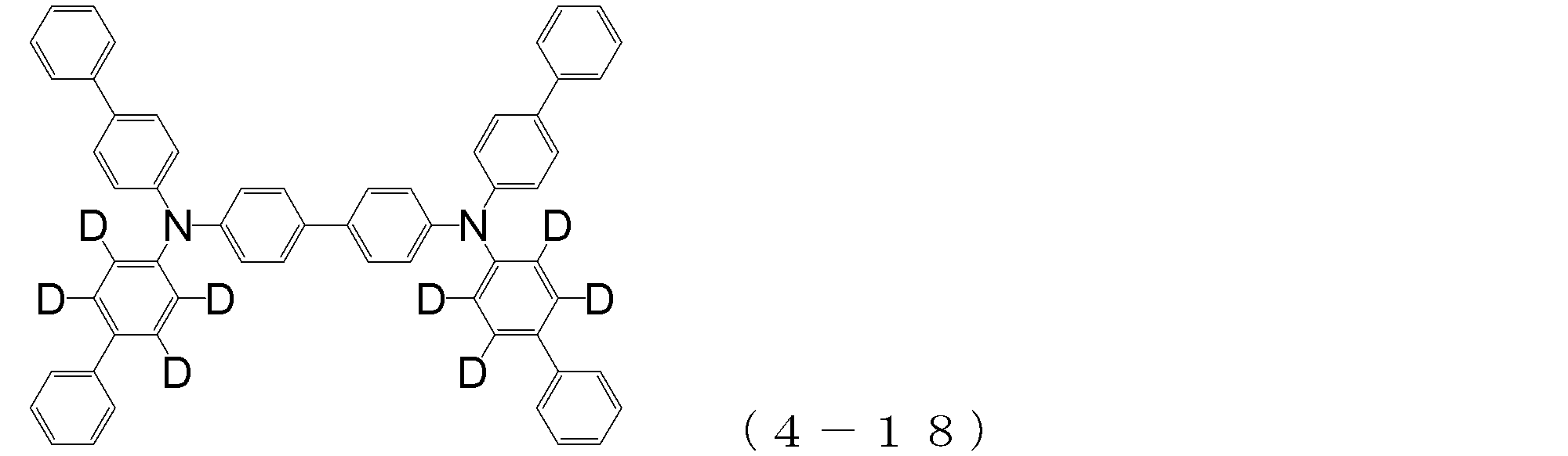

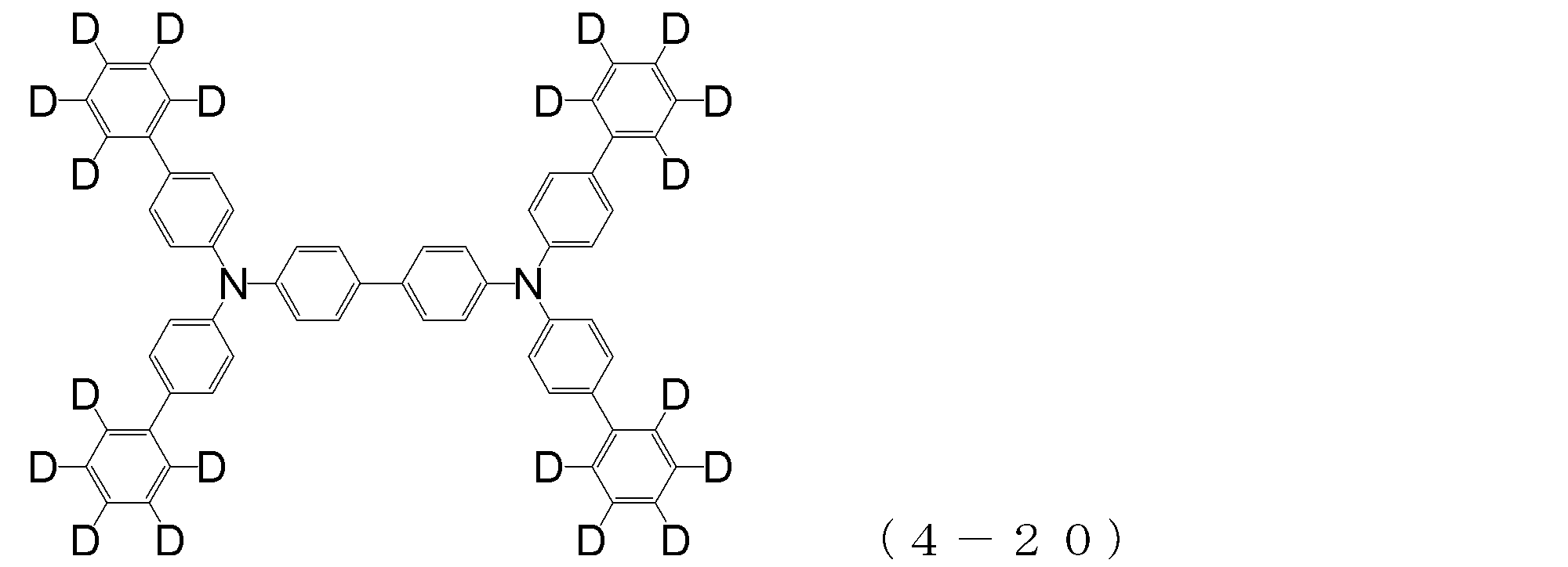

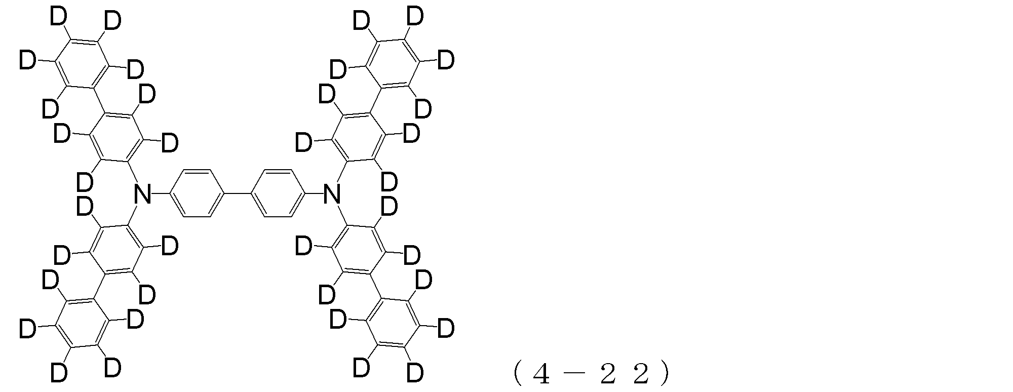
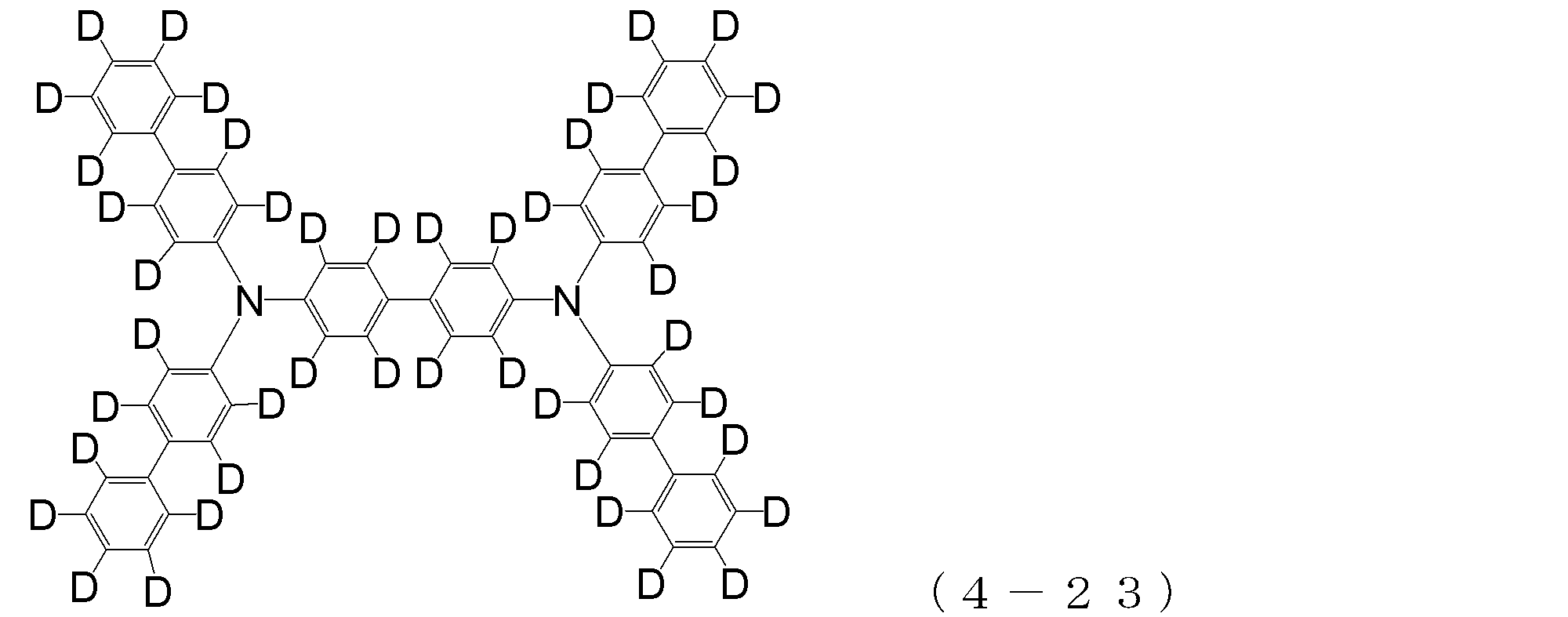

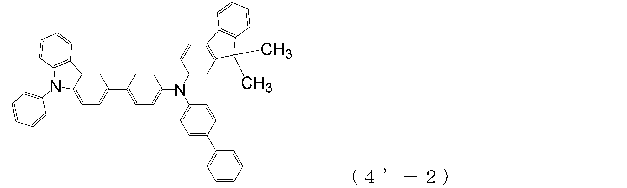
本発明の有機EL素子は、陽極と陰極との間に、正孔注入層、正孔輸送層、発光層及び電子輸送層がこの順に形成されているという基本構造を有しているものであり、特に、正孔注入層が、トリフェニルアミン骨格を有するアリールアミン化合物(α)により形成され、正孔輸送層は、トリフェニルアミン骨格を有するアリールアミン化合物(β)により形成され、さらに、電子輸送層が、前述した一般式(1)或いは(2)の電子輸送性化合物により形成されているという構造を有している。
以下、この有機EL素子を構成する各層について説明する。 <Structure of organic EL element>
The organic EL device of the present invention has a basic structure in which a hole injection layer, a hole transport layer, a light emitting layer, and an electron transport layer are formed in this order between an anode and a cathode. In particular, the hole injection layer is formed of an arylamine compound (α) having a triphenylamine skeleton, the hole transport layer is formed of an arylamine compound (β) having a triphenylamine skeleton, The transport layer has a structure in which the transport layer is formed of the electron transporting compound represented by the general formula (1) or (2).
Hereinafter, each layer which comprises this organic EL element is demonstrated.
本発明の有機EL素子において、陽極は、透明プラスチック基板(例えばポリエチレンテレフタレート基板)やガラス基板などの透明基板上への蒸着により設けられるものであり、ITOや金のような仕事関数の大きな電極材料により形成される。 <Anode and cathode>
In the organic EL device of the present invention, the anode is provided by vapor deposition on a transparent substrate such as a transparent plastic substrate (for example, a polyethylene terephthalate substrate) or a glass substrate, and an electrode material having a large work function such as ITO or gold. It is formed by.
正孔注入層は、前述したアリールアミン化合物(α)、即ち、トリフェニルアミン骨格を分子中に3個以上有する化合物により形成される。即ち、このアリールアミン化合物(α)は、正孔移動度が極めて大きく、しかも薄膜状態が安定に維持できる。従って、このような化合物を用いて正孔注入層を形成することにより、発光効率の向上、駆動電圧の低減及び長寿命化を実現できるのである。 <Hole injection layer>
The hole injection layer is formed of the above-described arylamine compound (α), that is, a compound having three or more triphenylamine skeletons in the molecule. That is, the arylamine compound (α) has a very high hole mobility and can maintain a thin film state stably. Therefore, by forming the hole injection layer using such a compound, it is possible to improve the light emission efficiency, reduce the driving voltage, and extend the life.
正孔注入層に隣接して設けられる正孔輸送層は、前述したアリールアミン化合物(β)、トリフェニルアミン骨格を分子中に2個有する化合物により形成される。
この正孔輸送層も、上述した正孔注入層と同様、アリールアミン化合物(β)以外の他の正孔輸送性化合物が併用されていてもよい。このような他の化合物は、アリールアミン化合物(β)との混合物の形で正孔輸送層を形成することができ、この場合、本発明の有機EL素子の性能が損なわれない範囲の量で(例えばアリールアミン化合物(β)当り50重量%以下)、併用すべきである。また、アリールアミン化合物(β)により形成された層に積層する形で、他の正孔輸送性化合物の層を1層或いは複数層設けることもできる。 <Hole transport layer>
The hole transport layer provided adjacent to the hole injection layer is formed of the arylamine compound (β) and the compound having two triphenylamine skeletons in the molecule.
This hole transport layer may also be used in combination with another hole transport compound other than the arylamine compound (β), similarly to the hole injection layer described above. Such other compounds can form the hole transport layer in the form of a mixture with the arylamine compound (β), and in this case, the amount is within a range that does not impair the performance of the organic EL device of the present invention. (For example, 50% by weight or less per arylamine compound (β)) should be used in combination. In addition, one or more layers of other hole transporting compounds can be provided in the form of being laminated on the layer formed of the arylamine compound (β).
発光層は、従来公知の有機EL素子に使用されているものと同じであり、例えば、Alq3等のキノリノール誘導体の金属錯体のほか、亜鉛、ベリリウム、アルミニウムなどの各種金属の錯体、アントラセン誘導体、ビススチリルベンゼン誘導体、ピレン誘導体、オキサゾール誘導体、ポリパラフェニレンビニレン誘導体などの発光材料を用いて発光層を形成することができる。さらには、前述した一般式(1)或いは一般式(2)で表されるアントラセン骨格とピリドインドール骨格を有する化合物を用いて発光層を形成することもできる。 <Light emitting layer>
The light emitting layer is the same as that used in conventionally known organic EL elements, for example, metal complexes of quinolinol derivatives such as Alq 3 , complexes of various metals such as zinc, beryllium, and aluminum, anthracene derivatives, The light-emitting layer can be formed using a light-emitting material such as a bisstyrylbenzene derivative, a pyrene derivative, an oxazole derivative, or a polyparaphenylene vinylene derivative. Furthermore, the light emitting layer can be formed using a compound having an anthracene skeleton and a pyridoindole skeleton represented by the general formula (1) or (2).
このときのホスト材料としては、4,4’-ジ(N-カルバゾリル)ビフェニル(CBP)、TCTA、mCPなどのカルバゾール誘導体などの正孔注入・輸送性のホスト材料を用いることができ、p-ビス(トリフェニルシリル)ベンゼン(UGH2)、2,2’,2’’-(1,3,5-フェニレン)-トリス(1-フェニル-1H-ベンズイミダゾール)(TPBI)などの電子輸送性のホスト材料も使用することができる。このようなホスト材料を使用することにより高性能の有機EL素子を作製することができる。 Further, a phosphorescent emitter can be used as the guest material. As the phosphorescent emitter, a phosphorescent emitter of a metal complex such as iridium or platinum can be used. For example, a green phosphorescent emitter such as Ir (ppy) 3 , a blue phosphorescent emitter such as FIrpic or FIr6, a red phosphorescent emitter such as Btp 2 Ir (acac), or the like is used.
As the host material at this time, a hole injecting / transporting host material such as 4,4′-di (N-carbazolyl) biphenyl (CBP), carbazole derivatives such as TCTA, mCP and the like can be used. Electron transport properties such as bis (triphenylsilyl) benzene (UGH2), 2,2 ′, 2 ″-(1,3,5-phenylene) -tris (1-phenyl-1H-benzimidazole) (TPBI) Host materials can also be used. By using such a host material, a high-performance organic EL element can be produced.
本発明の有機EL素子において、電子輸送層は、前述した一般式(1)或いは一般式(2)で表される電子輸送性化合物を用いて形成される。即ち、この電子輸送性化合物は、アントラセン骨格とピリドインドール骨格とを有しており、このような構造の電子輸送性化合物を用いて電子輸送層を形成することにより、前述した正孔注入層及び正孔輸送層が有する正孔注入・輸送特性とのバランスを確保でき、発光効率、駆動電圧、耐久性(長寿命)に関して優れた性能を発揮する有機EL素子が得られるのである。 <Electron transport layer>
In the organic EL device of the present invention, the electron transport layer is formed using the electron transport compound represented by the general formula (1) or the general formula (2) described above. That is, this electron transporting compound has an anthracene skeleton and a pyridoindole skeleton, and by forming an electron transporting layer using the electron transporting compound having such a structure, the hole injection layer described above is formed. In addition, a balance with the hole injection / transport characteristics of the hole transport layer can be secured, and an organic EL element exhibiting excellent performance in terms of light emission efficiency, drive voltage, and durability (long life) can be obtained.
本発明の有機EL素子においては、上述した特定の化合物を用いて正孔注入層、正孔輸送層及び電子輸送層が形成されている限りにおいて、必要に応じて、他の層を設けることができる。例えば、正孔輸送層と発光層との間には電子阻止層を設けることができ、発光層と電子輸送層との間には正孔阻止層を設けることができ、さらに、電子輸送層と陰極との間には電子注入層を設けることができる。 <Other layers>
In the organic EL device of the present invention, as long as the hole injection layer, the hole transport layer, and the electron transport layer are formed using the specific compound described above, other layers may be provided as necessary. it can. For example, an electron blocking layer can be provided between the hole transport layer and the light emitting layer, a hole blocking layer can be provided between the light emitting layer and the electron transport layer, and An electron injection layer can be provided between the cathode and the cathode.
電子阻止層は、注入された電子が発光層を通過してしまうことを阻止するために設けられるものである。電子阻止層を形成するための材料としては、電子阻止性を有する種々の化合物を使用することができ、下記のカルバゾール誘導体が代表的である。
4,4’,4’’-トリ(N-カルバゾリル)トリフェニルアミン
(TCTA);
9,9-ビス[4-(カルバゾール-9-イル)フェニル]フルオレン;
1,3-ビス(カルバゾール-9-イル)ベンゼン(mCP);
2,2-ビス(4-カルバゾール-9-イルフェニル)アダマンタン
(Ad-Cz);
また、上記のカルバゾール誘導体以外にも、9-[4-(カルバゾール-9-イル)フェニル]-9-[4-(トリフェニルシリル)フェニル]-9H-フルオレンに代表されるトリフェニルシリル基を有しており且つトリアリールアミン骨格を分子中に有している化合物なども、電子阻止層形成用の材料として使用することができる。 Electron blocking layer;
The electron blocking layer is provided to prevent injected electrons from passing through the light emitting layer. As a material for forming the electron blocking layer, various compounds having an electron blocking property can be used, and the following carbazole derivatives are typical.
4,4 ′, 4 ″ -tri (N-carbazolyl) triphenylamine (TCTA);
9,9-bis [4- (carbazol-9-yl) phenyl] fluorene;
1,3-bis (carbazol-9-yl) benzene (mCP);
2,2-bis (4-carbazol-9-ylphenyl) adamantane (Ad-Cz);
In addition to the above carbazole derivatives, a triphenylsilyl group represented by 9- [4- (carbazol-9-yl) phenyl] -9- [4- (triphenylsilyl) phenyl] -9H-fluorene is also included. A compound having a triarylamine skeleton in the molecule can also be used as a material for forming an electron blocking layer.
正孔阻止層は、注入された正孔が発光層を通過してしまうことを阻止するために設けられるものであり、バソクプロイン(BCP)などのフェナントロリン誘導体、アルミニウム(III)ビス(2-メチル-8-キノリナート)-4-フェニルフェノレート(BAlq)などのキノリノール誘導体の金属錯体の他、各種の希土類錯体、トリアゾール誘導体、トリアジン誘導体、オキサジアゾール誘導体など、正孔阻止作用を有する化合物により形成される。 Hole blocking layer;
The hole blocking layer is provided to prevent injected holes from passing through the light emitting layer, and includes a phenanthroline derivative such as bathocuproine (BCP), aluminum (III) bis (2-methyl- In addition to metal complexes of quinolinol derivatives such as 8-quinolinato) -4-phenylphenolate (BAlq), various rare earth complexes, triazole derivatives, triazine derivatives, oxadiazole derivatives, etc. The
電子注入層は、フッ化リチウム、フッ化セシウムなどのアルカリ金属塩、フッ化マグネシウムなどのアルカリ土類金属塩、酸化アルミニウムなどの金属酸化物などを用いて形成することができる。 Electron injection layer;
The electron injection layer can be formed using an alkali metal salt such as lithium fluoride or cesium fluoride, an alkaline earth metal salt such as magnesium fluoride, or a metal oxide such as aluminum oxide.
上述した構造を有する本発明の有機EL素子は、例えば陽極、陰極、及び陽極と陰極の間の正孔注入層、正孔輸送層、発光層、電子輸送層、及び適宜設けられる電子阻止層、正孔阻止層、電子注入層などを、その材料の種類に応じて、蒸着法、スピンコート法、インクジェット法等の公知の方法によって透明基板上に成膜することによって製造することができる。 <Manufacture of organic EL elements>
The organic EL device of the present invention having the structure described above includes, for example, an anode, a cathode, a hole injection layer between the anode and the cathode, a hole transport layer, a light emitting layer, an electron transport layer, and an electron blocking layer provided as appropriate. A hole blocking layer, an electron injection layer, and the like can be produced by forming a film on a transparent substrate by a known method such as a vapor deposition method, a spin coating method, or an ink jet method, depending on the type of the material.
8-(9,10-ジフェニルアントラセン-2-イル)-5-フェニル-5H-ピリド[4,3-b]インドール[化合物(2-1)]の合成;
窒素置換した反応容器に、
ヨードベンゼン 43.0ml、
5H-ピリド[4,3-b]インドール 50.0g、
銅粉 1.9g、
炭酸カリウム 82.2g、
ジメチルスルホキシド 2.1ml、
を加えて加熱し、170℃で3時間攪拌した。100℃まで冷却し、さらにトルエン500mlを加えて、100℃で1時間攪拌した。不溶物をろ過によって除き、ろ液を減圧下で濃縮することによって粗製物を得た。
粗製物をカラムクロマトグラフ(担体:NHシリカゲル、溶離液:トルエン)によって精製し、5-フェニル-5H-ピリド[4,3-b]インドールの黄色液体69.9g(収率96%)を得た。 <Example 1>
Synthesis of 8- (9,10-diphenylanthracen-2-yl) -5-phenyl-5H-pyrido [4,3-b] indole [compound (2-1)];
In a reaction vessel purged with nitrogen,
43.0 ml of iodobenzene,
5H-pyrido [4,3-b] indole 50.0 g,
1.9 g of copper powder,
82.2g of potassium carbonate,
2.1 ml of dimethyl sulfoxide,
The mixture was heated and stirred at 170 ° C. for 3 hours. The mixture was cooled to 100 ° C., 500 ml of toluene was further added, and the mixture was stirred at 100 ° C. for 1 hour. Insoluble matter was removed by filtration, and the filtrate was concentrated under reduced pressure to obtain a crude product.
The crude product was purified by column chromatography (carrier: NH silica gel, eluent: toluene) to give 69.9 g of 5-phenyl-5H-pyrido [4,3-b] indole as a yellow liquid (yield 96%). It was.
ジメチルホルムアミド 150ml
を窒素置換した反応容器に加え、攪拌しながら、
N-ブロモスクシンイミド 23.8g
を加えて加熱し、50℃で10時間攪拌した。室温まで冷却し、クロロホルム300ml、水300mlを加えた後に攪拌し、その後有機相を分液した。有機相を無水硫酸マグネシウムで脱水した後、減圧下で濃縮することによって粗製物を得た。
この粗製物をカラムクロマトグラフ(担体:NHシリカゲル、溶離液:トルエン/ヘキサン)によって精製し、8-ブロモ-5-フェニル-5H-ピリド[4,3-b]インドールの黄色液体18.0g(収率50%)を得た。 27.2 g of indole compound yellow liquid obtained above
Dimethylformamide 150ml
To a reaction vessel purged with nitrogen and stirring,
N-bromosuccinimide 23.8g
The mixture was heated and stirred at 50 ° C. for 10 hours. After cooling to room temperature, 300 ml of chloroform and 300 ml of water were added and stirred, and then the organic phase was separated. The organic phase was dehydrated with anhydrous magnesium sulfate and then concentrated under reduced pressure to obtain a crude product.
This crude product was purified by column chromatography (carrier: NH silica gel, eluent: toluene / hexane), and 18.0 g of a yellow liquid of 8-bromo-5-phenyl-5H-pyrido [4,3-b] indole ( Yield 50%).
9,10-ジフェニルアントラセン-2-ボロン酸 3.6g、
テトラキス(トリフェニルホスフィン)パラジウム 0.1g、
2M炭酸カリウム水溶液 22ml、
トルエン 60ml、
エタノール 15ml、
を窒素置換した反応容器に加えて加熱し、攪拌しながら16時間還流した。室温まで冷却し、トルエン100ml、飽和食塩水100mlを加えた後に攪拌し、その後有機相を分液した。
この有機相を無水硫酸マグネシウムで脱水した後、減圧下で濃縮することによって粗製物を得た。
粗製物をカラムクロマトグラフ(担体:NHシリカゲル、溶離液:トルエン/ヘキサン)によって精製し、8-(9,10-ジフェニルアントラセン-2-イル)-5-フェニル-5H-ピリド[4,3-b]インドール[化合物(2-1)]の黄色粉体3.0g(収率61%)を得た。 2.8 g of the bromide of pyridoindole obtained above,
3.6 g of 9,10-diphenylanthracene-2-boronic acid,
0.1 g of tetrakis (triphenylphosphine) palladium,
22 ml of 2M aqueous potassium carbonate solution,
60 ml of toluene,
15 ml of ethanol,
Was added to a nitrogen-substituted reaction vessel, heated, and refluxed for 16 hours with stirring. After cooling to room temperature, 100 ml of toluene and 100 ml of saturated brine were added and stirred, and then the organic phase was separated.
The organic phase was dehydrated with anhydrous magnesium sulfate and then concentrated under reduced pressure to obtain a crude product.
The crude product was purified by column chromatography (carrier: NH silica gel, eluent: toluene / hexane), and 8- (9,10-diphenylanthracen-2-yl) -5-phenyl-5H-pyrido [4,3- b] 3.0 g (yield 61%) of a yellow powder of indole [compound (2-1)] was obtained.
1H-NMR(CDCl3)で以下の28個の水素のシグナルを検出した。
δ(ppm)=9.39(1H)
=8.52(1H)
=8.36(1H)
=7.98(1H)
=7.84(1H)
=7.74(3H)
=7.50-7.67(16H)
=7.45(1H)
=7.35(2H)
=7.29(1H) The structure of the obtained yellow powder was identified using NMR.
The following 28 hydrogen signals were detected by 1 H-NMR (CDCl 3 ).
δ (ppm) = 9.39 (1H)
= 8.52 (1H)
= 8.36 (1H)
= 7.98 (1H)
= 7.84 (1H)
= 7.74 (3H)
= 7.50-7.67 (16H)
= 7.45 (1H)
= 7.35 (2H)
= 7.29 (1H)
8-〔9,10-ジ(ナフタレン-2-イル)-アントラセン-2-イル〕-5-フェニル-5H-ピリド[4,3-b]インドール[化合物(2-2)]の合成;
実施例1で得られたピリドインドールのブロモ化物(8-ブロモ-5-フェニル-5H-ピリド[4,3-b]インドールを用いて、次のようにして合成を行った。
上記のピリドインドールのブロモ化物 2.0g
9,10-ジ(ナフタレン-2-イル)アントラセン-2-ボロン酸
3.5g
テトラキス(トリフェニルホスフィン)パラジウム 0.4g
2M炭酸カリウム水溶液 10ml
トルエン 20ml
エタノール 5ml
を窒素置換した反応容器に加えて加熱し、攪拌しながら5.5時間還流した。室温まで冷却し、トルエン50ml、水30mlを加えた後に攪拌し、その後、有機相を分液した。この有機相を無水硫酸マグネシウムで脱水した後、減圧下で濃縮することによって粗製物を得た。
粗製物をカラムクロマトグラフ(担体:NHシリカゲル、溶離液:トルエン)によって精製し、8-〔9,10-ジ(ナフタレン-2-イル)-アントラセン-2-イル〕-5-フェニル-5H-ピリド[4,3-b]インドール[化合物(2-2)]の黄色粉体2.2g(収率53%)を得た。 <Example 2>
Synthesis of 8- [9,10-di (naphthalen-2-yl) -anthracen-2-yl] -5-phenyl-5H-pyrido [4,3-b] indole [compound (2-2)];
Using the bromide of pyridoindole obtained in Example 1 (8-bromo-5-phenyl-5H-pyrido [4,3-b] indole, synthesis was performed as follows.
2.0 g of bromide of pyridoindole
9,10-di (naphthalen-2-yl) anthracene-2-boronic acid 3.5 g
Tetrakis (triphenylphosphine) palladium 0.4g
2M aqueous potassium carbonate solution 10ml
Toluene 20ml
5 ml of ethanol
Was added to a reaction vessel purged with nitrogen, heated, and refluxed for 5.5 hours with stirring. The mixture was cooled to room temperature, 50 ml of toluene and 30 ml of water were added and stirred, and then the organic phase was separated. The organic phase was dehydrated with anhydrous magnesium sulfate and then concentrated under reduced pressure to obtain a crude product.
The crude product was purified by column chromatography (carrier: NH silica gel, eluent: toluene) and 8- [9,10-di (naphthalen-2-yl) -anthracen-2-yl] -5-phenyl-5H- As a result, 2.2 g (yield 53%) of a yellow powder of pyrido [4,3-b] indole [compound (2-2)] was obtained.
1H-NMR(CDCl3)で以下の32個の水素のシグナルを検出した。
δ(ppm)=9.32(1H)
=8.48(1H)
=8.32(1H)
=8.11(2H)
=8.02-8.07(5H)
=7.95(2H)
=7.88(1H)
=7.68-7.78(5H)
=7.58-7.64(7H)
=7.49(3H)
=7.37(1H)
=7.33(2H)
=7.24(1H) The structure of the obtained yellow powder was identified using NMR.
The following 32 hydrogen signals were detected by 1 H-NMR (CDCl 3 ).
δ (ppm) = 9.32 (1H)
= 8.48 (1H)
= 8.32 (1H)
= 8.11 (2H)
= 8.02-8.07 (5H)
= 7.95 (2H)
= 7.88 (1H)
= 7.68-7.78 (5H)
= 7.58-7.64 (7H)
= 7.49 (3H)
= 7.37 (1H)
= 7.33 (2H)
= 7.24 (1H)
8-〔4-[10-(ナフタレン-2-イル)アントラセン-9-イル]フェニル〕-5-フェニル-5H-ピリド[4,3-b]インドール[化合物(1-6)]の合成;
8-(4-ブロモフェニル)-5-フェニル-5H-ピリド[4,3-b]インドールを合成し、このピリドインドール誘導体を原料として用いた。
窒素置換した反応容器に、
上記ピリドインドール誘導体 4.0g
10-(ナフタレン-2-イル)アントラセン-9-ボロン酸
4.1g
テトラキス(トリフェニルホスフィン)パラジウム 0.3g
2M炭酸カリウム水溶液 15ml
トルエン 32ml
エタノール 8ml
を加えて加熱し、攪拌しながら18時間還流した。室温まで冷却し、ろ過により析出物を採取した。析出物を1,2-ジクロロベンゼンに加熱しながら溶解し、不溶物をろ過によって除いた後、ろ液を減圧下で濃縮することによって粗製物を得た。
粗製物を1,2-ジクロロベンゼンによる再結晶によって精製し、8-〔4-(10-ナフタレン-2-イル-アントラセン-9-イル)-フェニル〕-5-フェニル-5H-ピリド[4,3-b]インドール[化合物(1-6)]の黄色粉体2.5g(収率40%)を得た。 <Example 3>
Synthesis of 8- [4- [10- (naphthalen-2-yl) anthracen-9-yl] phenyl] -5-phenyl-5H-pyrido [4,3-b] indole [compound (1-6)];
8- (4-Bromophenyl) -5-phenyl-5H-pyrido [4,3-b] indole was synthesized and this pyridoindole derivative was used as a raw material.
In a reaction vessel purged with nitrogen,
4.0 g of the above pyridoindole derivative
4.1 g of 10- (naphthalen-2-yl) anthracene-9-boronic acid
Tetrakis (triphenylphosphine) palladium 0.3g
2M aqueous potassium carbonate solution 15ml
Toluene 32ml
8 ml of ethanol
The mixture was heated and refluxed for 18 hours with stirring. After cooling to room temperature, the precipitate was collected by filtration. The precipitate was dissolved in 1,2-dichlorobenzene while heating, the insoluble matter was removed by filtration, and the filtrate was concentrated under reduced pressure to obtain a crude product.
The crude product was purified by recrystallization from 1,2-dichlorobenzene to give 8- [4- (10-naphthalen-2-yl-anthracen-9-yl) -phenyl] -5-phenyl-5H-pyrido [4, 2.5 g (yield 40%) of a yellow powder of 3-b] indole [compound (1-6)] was obtained.
1H-NMR(CDCl3)で以下の30個の水素のシグナルを検出した。
δ(ppm)=9.50(1H)
=8.62(1H)
=8.57(1H)
=8.09(1H)
=8.04(1H)
=7.99(3H)
=7.92(2H)
=7.87(2H)
=7.75(2H)
=7.66-7.72(2H)
=7.55-7.66(9H)
=7.30-7.40(5H) The structure of the obtained yellow powder was identified using NMR.
The following 30 hydrogen signals were detected by 1 H-NMR (CDCl 3 ).
δ (ppm) = 9.50 (1H)
= 8.62 (1H)
= 8.57 (1H)
= 8.09 (1H)
= 8.04 (1H)
= 7.9 (3H)
= 7.92 (2H)
= 7.87 (2H)
= 7.75 (2H)
= 7.66-7.72 (2H)
= 7.55-7.66 (9H)
= 7.30-7.40 (5H)
8-〔3-[10-(ナフタレン-2-イル)アントラセン-9-イル]フェニル〕-5-フェニル-5H-ピリド[4,3-b]インドール[化合物(1-11)]の合成;
実施例3と同様、8-(3-クロロフェニル)-5-フェニル-5H-ピリド[4,3-b]インドールを合成し、このピリドインドール誘導体を原料として用いた。
窒素置換した反応容器に、
上記のピリドインドール誘導体 2.85g
10-(ナフタレン-2-イル)アントラセン-9-ボロン酸
3.35g
酢酸パラジウム 0.05g
ブチルジアダマンチルホスフィン 0.17g
りん酸三カリウム 5.11g
キシレン 29ml
を加えて加熱し、攪拌しながら26時間還流した。室温まで冷却し、トルエン50ml、水100mlを加えた後に攪拌し、その後有機相を分液した。有機相を無水硫酸マグネシウムで脱水した後、減圧下で濃縮することによって粗製物を得た。
粗製物をカラムクロマトグラフ(担体:NHシリカゲル、溶離液:トルエン/ヘキサン)によって精製し、8-〔3-[10-(ナフタレン-2-イル)アントラセン-9-イル]フェニル〕-5-フェニル-5H-ピリド[4,3-b]インドール[化合物(1-11)]の黄白色粉体1.81g(収率36.2%)を得た。 <Example 4>
Synthesis of 8- [3- [10- (naphthalen-2-yl) anthracen-9-yl] phenyl] -5-phenyl-5H-pyrido [4,3-b] indole [compound (1-11)];
In the same manner as in Example 3, 8- (3-chlorophenyl) -5-phenyl-5H-pyrido [4,3-b] indole was synthesized and this pyridoindole derivative was used as a raw material.
In a reaction vessel purged with nitrogen,
2.85 g of the above pyridoindole derivative
10.35 g of 10- (naphthalen-2-yl) anthracene-9-boronic acid
Palladium acetate 0.05g
Butyldiadamantylphosphine 0.17 g
Tripotassium phosphate 5.11 g
Xylene 29ml
The mixture was heated and refluxed for 26 hours with stirring. The mixture was cooled to room temperature, 50 ml of toluene and 100 ml of water were added and stirred, and then the organic phase was separated. The organic phase was dehydrated with anhydrous magnesium sulfate and then concentrated under reduced pressure to obtain a crude product.
The crude product was purified by column chromatography (carrier: NH silica gel, eluent: toluene / hexane) and 8- [3- [10- (naphthalen-2-yl) anthracen-9-yl] phenyl] -5-phenyl 1.81 g (yield 36.2%) of a yellowish white powder of -5H-pyrido [4,3-b] indole [compound (1-11)] was obtained.
1H-NMR(CDCl3)で以下の30個の水素のシグナルを検出した。
δ(ppm)=9.41(1H)
=8.52(2H)
=8.08(1H)
=8.02(1H)
=8.00(1H)
=7.93(2H)
=7.90(1H)
=7.87(2H)
=7.83(1H)
=7.76-7.73(3H)
=7.62(5H)
=7.56(2H)
=7.54-7.49(3H)
=7.37(2H)
=7.31(3H) The structure of the obtained yellowish white powder was identified using NMR.
The following 30 hydrogen signals were detected by 1 H-NMR (CDCl 3 ).
δ (ppm) = 9.41 (1H)
= 8.52 (2H)
= 8.08 (1H)
= 8.02 (1H)
= 8.00 (1H)
= 7.93 (2H)
= 7.90 (1H)
= 7.87 (2H)
= 7.83 (1H)
= 7.76-7.73 (3H)
= 7.62 (5H)
= 7.56 (2H)
= 7.54-7.49 (3H)
= 7.37 (2H)
= 7.31 (3H)
8-〔4-[10-フェニルアントラセン-9-イル]ナフタレン-1-イル〕-5-フェニル-5H-ピリド[4,3-b]インドール[化合物(1-15)]の合成;
実施例3と同様、8-(4-ブロモナフタレン-1-イル)-5-フェニル-5H-ピリド[4,3-b]インドール)を合成し、このピリドインドール誘導体を原料として用いた。
窒素置換した反応容器に、
上記のピリドインドール誘導体 4.00g
10-フェニルアントラセン-9-ボロン酸 2.92g
テトラキス(トリフェニルホスフィン)パラジウム 0.51g
2M炭酸カリウム水溶液 8ml
ジオキサン 32ml
を加えて加熱し、攪拌しながら20時間還流した。室温まで冷却し、トルエン、水を加えた後に攪拌し、その後有機相を分液した。この有機相を無水硫酸マグネシウムで脱水した後、減圧下で濃縮することによって粗製物を得た。
粗製物をカラムクロマトグラフ(担体:NHシリカゲル、溶離液:トルエン)によって精製した後、アセトンとメタノールの混合溶媒による晶析、o-ジクロロベンゼンとヘキサンの混合溶媒による晶析を繰り返すことによって、8-〔4-[10-フェニルアントラセン-9-イル]ナフタレン-1-イル〕-5-フェニル-5H-ピリド[4,3-b]インドール[化合物(1-15)]の黄白色粉体3.20g(収率58%)を得た。 <Example 5>
Synthesis of 8- [4- [10-phenylanthracen-9-yl] naphthalen-1-yl] -5-phenyl-5H-pyrido [4,3-b] indole [compound (1-15)];
In the same manner as in Example 3, 8- (4-bromonaphthalen-1-yl) -5-phenyl-5H-pyrido [4,3-b] indole) was synthesized, and this pyridoindole derivative was used as a raw material.
In a reaction vessel purged with nitrogen,
4.00 g of the above pyridoindole derivative
10-phenylanthracene-9-boronic acid 2.92 g
Tetrakis (triphenylphosphine) palladium 0.51g
2M aqueous potassium carbonate solution 8ml
Dioxane 32ml
The mixture was heated and refluxed with stirring for 20 hours. The mixture was cooled to room temperature, stirred after adding toluene and water, and then the organic phase was separated. The organic phase was dehydrated with anhydrous magnesium sulfate and then concentrated under reduced pressure to obtain a crude product.
After the crude product was purified by column chromatography (carrier: NH silica gel, eluent: toluene), crystallization with a mixed solvent of acetone and methanol and crystallization with a mixed solvent of o-dichlorobenzene and hexane were repeated. Yellowish white powder 3 of [4- [10-phenylanthracen-9-yl] naphthalen-1-yl] -5-phenyl-5H-pyrido [4,3-b] indole [compound (1-15)] .20 g (yield 58%) was obtained.
1H-NMR(CDCl3)で以下の30個の水素のシグナルを検出した。
δ(ppm)=9.47(1H)
=8.59(1H)
=8.54(1H)
=8.16(1H)
=7.84-7.55(18H)
=7.46(1H)
=7.39-7.34(3H)
=7.30-7.26(4H) The structure of the obtained yellowish white powder was identified using NMR.
The following 30 hydrogen signals were detected by 1 H-NMR (CDCl 3 ).
δ (ppm) = 9.47 (1H)
= 8.59 (1H)
= 8.54 (1H)
= 8.16 (1H)
= 7.84-7.55 (18H)
= 7.46 (1H)
= 7.39-7.34 (3H)
= 7.30-7.26 (4H)
8-〔4-[10-(ナフタレン-1-イル)アントラセン-9-イル]ナフタレン-1-イル〕-5-フェニル-5H-ピリド[4,3-b]インドール[化合物(1-17)]の合成;
実施例5と同様、ピリドインドール誘導体(8-(4-ブロモナフタレン-1-イル)-5-フェニル-5H-ピリド[4,3-b]インドール)を使用し、次の合成反応を行った。
窒素置換した反応容器に、
上記のピリドインドール誘導体 3.50g
10-(ナフタレン-1-イル)アントラセン-9-ボロン酸
3.26g
テトラキス(トリフェニルホスフィン)パラジウム 0.45g
2M炭酸カリウム水溶液 7ml
ジオキサン 30ml
を加えて加熱し、攪拌しながら20時間還流した。室温まで冷却し、トルエン、水を加えた後に攪拌し、その後有機相を分液した。この有機相を無水硫酸マグネシウムで脱水した後、減圧下で濃縮することによって粗製物を得た。
粗製物をトルエンとヘキサンの混合溶媒による晶析、シリカゲルによる吸着精製、メタノール洗浄、トルエンとヘキサンの混合溶媒による晶析、トルエンとメタノールの混合溶媒による晶析を繰り返すことによって、8-〔4-[10-(ナフタレン-1-イル)アントラセン-9-イル]ナフタレン-1-イル〕-5-フェニル-5H-ピリド[4,3-b]インドール[化合物(1-17)]の白色粉体1.60g(収率31%)を得た。 <Example 6>
8- [4- [10- (Naphthalen-1-yl) anthracen-9-yl] naphthalen-1-yl] -5-phenyl-5H-pyrido [4,3-b] indole [compound (1-17) ] Synthesis;
As in Example 5, the following synthesis reaction was performed using a pyridoindole derivative (8- (4-bromonaphthalen-1-yl) -5-phenyl-5H-pyrido [4,3-b] indole). It was.
In a reaction vessel purged with nitrogen,
3.50 g of the above pyridoindole derivative
10- (Naphthalen-1-yl) anthracene-9-boronic acid 3.26 g
Tetrakis (triphenylphosphine) palladium 0.45g
2M aqueous potassium carbonate solution 7ml
Dioxane 30ml
The mixture was heated and refluxed with stirring for 20 hours. The mixture was cooled to room temperature, stirred after adding toluene and water, and then the organic phase was separated. The organic phase was dehydrated with anhydrous magnesium sulfate and then concentrated under reduced pressure to obtain a crude product.
The crude product was crystallized with a mixed solvent of toluene and hexane, adsorbed and purified with silica gel, washed with methanol, crystallized with a mixed solvent of toluene and hexane, and crystallized with a mixed solvent of toluene and methanol. White powder of [10- (naphthalen-1-yl) anthracen-9-yl] naphthalen-1-yl] -5-phenyl-5H-pyrido [4,3-b] indole [compound (1-17)] 1.60 g (yield 31%) was obtained.
1H-NMR(CDCl3)で以下の32個の水素のシグナルを検出した。
δ(ppm)=9.48(1H)
=8.59-8.56(2H)
=8.19-8.04(3H)
=7.85-7.46(17H)
=7.40-7.25(9H) The structure of the obtained white powder was identified using NMR.
The following 32 hydrogen signals were detected by 1 H-NMR (CDCl 3 ).
δ (ppm) = 9.48 (1H)
= 8.59-8.56 (2H)
= 8.19-8.04 (3H)
= 7.85-7.46 (17H)
= 7.40-7.25 (9H)
8-〔4-[10-(ナフタレン-2-イル)アントラセン-9-イル]ナフタレン-1-イル〕-5-フェニル-5H-ピリド[4,3-b]インドール[化合物(1-18)]の合成;
実施例5と同様、ピリドインドール誘導体(8-(4-ブロモナフタレン-1-イル)-5-フェニル-5H-ピリド[4,3-b]インドール)を使用し、次の合成反応を行った。
窒素置換した反応容器に、
上記のピリドインドール誘導体 2.30g
10-(ナフタレン-2-イル)アントラセン-9-ボロン酸
2.31g
テトラキス(トリフェニルホスフィン)パラジウム 0.30g
2M炭酸カリウム水溶液 5ml
ジオキサン 18ml
を加えて加熱し、攪拌しながら20時間還流した。室温まで冷却し、トルエン、水を加えた後に攪拌し、その後有機相を分液した。この有機相を無水硫酸マグネシウムで脱水した後、減圧下で濃縮することによって粗製物を得た。
粗製物をカラムクロマトグラフ(担体:NHシリカゲル、溶離液:トルエン/ヘキサン)によって精製した後、トルエンとヘキサンの混合溶媒による晶析、メタノール洗浄、アセトンとメタノールの混合溶媒による晶析を繰り返すことによって、8-〔4-[10-(ナフタレン-2-イル)アントラセン-9-イル]ナフタレン-1-イル〕-5-フェニル-5H-ピリド[4,3-b]インドール[化合物(1-18)]の黄色固体0.95g(収率28%)を得た。 <Example 7>
8- [4- [10- (Naphthalen-2-yl) anthracen-9-yl] naphthalen-1-yl] -5-phenyl-5H-pyrido [4,3-b] indole [compound (1-18) ] Synthesis;
As in Example 5, the following synthesis reaction was performed using a pyridoindole derivative (8- (4-bromonaphthalen-1-yl) -5-phenyl-5H-pyrido [4,3-b] indole). It was.
In a reaction vessel purged with nitrogen,
2.30 g of the above pyridoindole derivative
10- (Naphthalen-2-yl) anthracene-9-boronic acid 2.31 g
Tetrakis (triphenylphosphine) palladium 0.30g
2M aqueous potassium carbonate solution 5ml
Dioxane 18ml
The mixture was heated and refluxed with stirring for 20 hours. The mixture was cooled to room temperature, stirred after adding toluene and water, and then the organic phase was separated. The organic phase was dehydrated with anhydrous magnesium sulfate and then concentrated under reduced pressure to obtain a crude product.
The crude product is purified by column chromatography (carrier: NH silica gel, eluent: toluene / hexane), then crystallized with a mixed solvent of toluene and hexane, washed with methanol, and crystallized with a mixed solvent of acetone and methanol. 8- [4- [10- (naphthalen-2-yl) anthracen-9-yl] naphthalen-1-yl] -5-phenyl-5H-pyrido [4,3-b] indole [compound (1-18 )] As a yellow solid (yield 28%).
1H-NMR(CDCl3)で以下の32個の水素のシグナルを検出した。
δ(ppm)=9.47(1H)
=8.59(1H)
=8.55(1H)
=8.17-8.05(4H)
=7.96(1H)
=7.83-7.78(4H)
=7.74-7.58(12H)
=7.45(1H)
=7.38(1H)
=7.34-7.27(6H) The structure of the obtained yellow solid was identified using NMR.
The following 32 hydrogen signals were detected by 1 H-NMR (CDCl 3 ).
δ (ppm) = 9.47 (1H)
= 8.59 (1H)
= 8.55 (1H)
= 8.17-8.05 (4H)
= 7.96 (1H)
= 7.83-7.78 (4H)
= 7.74-7.58 (12H)
= 7.45 (1H)
= 7.38 (1H)
= 7.34-7.27 (6H)
下記の手順で、図1に示す構造の有機EL素子を作製した。即ち、この有機EL素子は、ガラス基板1上に透明陽極2(ITO電極)、正孔注入層3、正孔輸送層4、発光層5、電子輸送層6、電子注入層7、陰極(アルミニウム電極)8が順に蒸着により設けられた構造を有している。 <Example 8>
The organic EL element having the structure shown in FIG. 1 was produced by the following procedure. That is, this organic EL element is formed on a glass substrate 1 with a transparent anode 2 (ITO electrode), a hole injection layer 3, a hole transport layer 4, a light emitting layer 5, an electron transport layer 6, an electron injection layer 7, a cathode (aluminum). Electrode) 8 has a structure provided in order by vapor deposition.
続いて、下記化合物(3-1)を用いての蒸着により、透明陽極2を覆うように膜厚20nmの正孔注入層3を形成した。

Subsequently, a hole injection layer 3 having a thickness of 20 nm was formed so as to cover the transparent anode 2 by vapor deposition using the following compound (3-1).
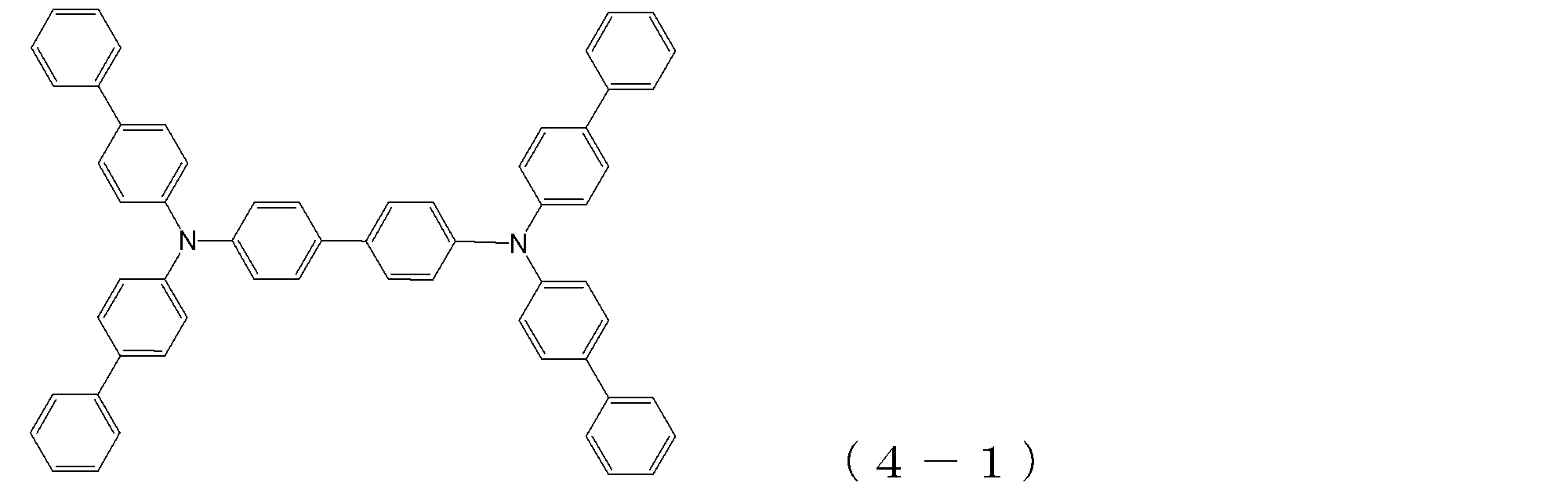


最後に、アルミニウムを150nm蒸着して陰極8を形成した。 On the electron transport layer 6, lithium fluoride was deposited as an electron injection layer 7 so as to have a film thickness of 0.5 nm.
Finally, 150 nm of aluminum was deposited to form the cathode 8.
化合物2-1に代えて下記構造式の化合物2-2を用いて膜厚30nmの電子輸送層6を形成した以外は、実施例8と同様の条件で有機EL素子を作製した。

An organic EL device was produced under the same conditions as in Example 8, except that Compound 2-2 having the following structural formula was used instead of Compound 2-1 to form an electron transport layer 6 having a thickness of 30 nm.
化合物2-1に代えて下記構造式の化合物1-6を用いて膜厚30nmの電子輸送層6を形成した以外は、実施例8と同様の条件で有機EL素子を作製した。

An organic EL device was produced under the same conditions as in Example 8 except that the compound 1-6 having the following structural formula was used in place of the compound 2-1, and the electron transport layer 6 having a thickness of 30 nm was formed.
化合物2-1に代えて下記構造式の化合物1-11を用いて膜厚30nmの電子輸送層6を形成した以外は、実施例8と同様の条件で有機EL素子を作製した。
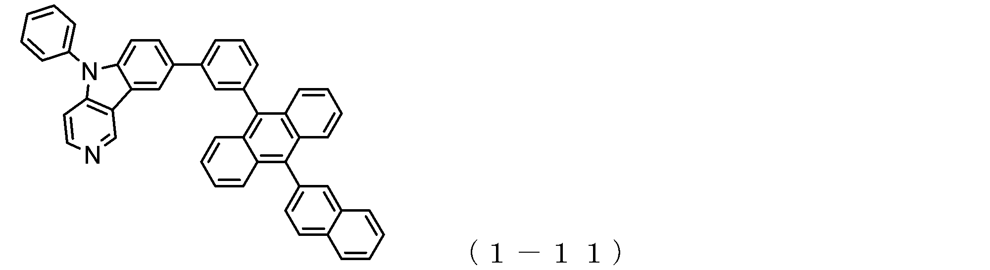
An organic EL device was produced under the same conditions as in Example 8, except that Compound 1-11 having the following structural formula was used instead of Compound 2-1, and an electron transport layer 6 having a thickness of 30 nm was formed.
化合物2-1に代えて下記構造式の化合物1-15を用いて膜厚30nmの電子輸送層6を形成した以外は、実施例8と同様の条件で有機EL素子を作製した。
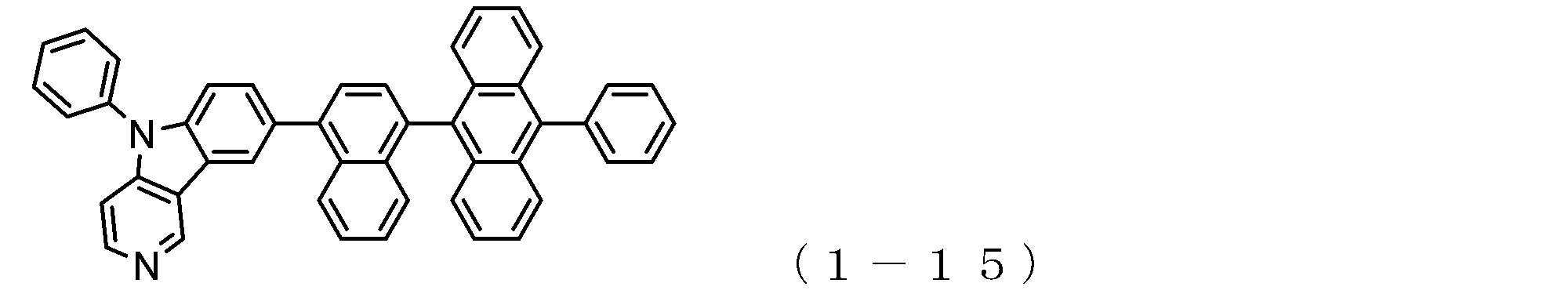
An organic EL device was produced under the same conditions as in Example 8, except that Compound 1-15 having the following structural formula was used in place of Compound 2-1 to form an electron transport layer 6 having a thickness of 30 nm.
化合物2-1に代えて下記構造式の化合物1-17を用いて膜厚30nmの電子輸送層6を形成した以外は、実施例8と同様の条件で有機EL素子を作製した。
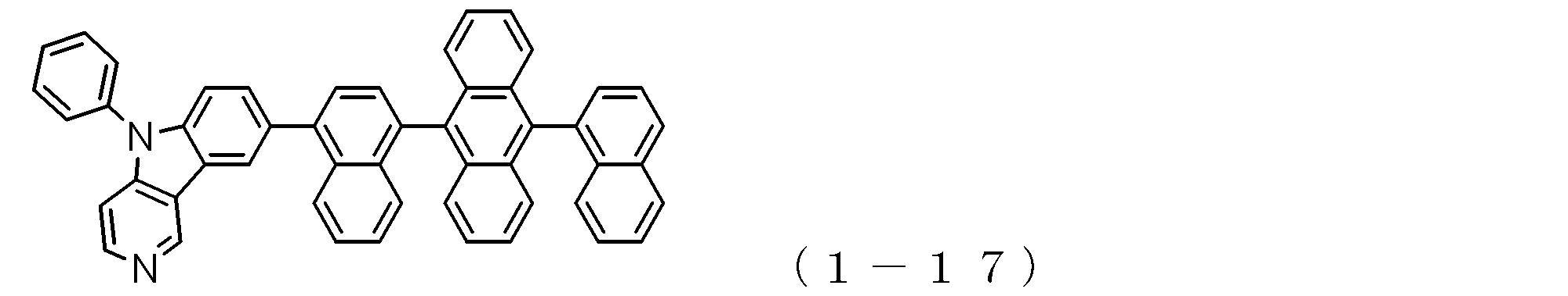
An organic EL device was produced under the same conditions as in Example 8, except that Compound 1-17 having the following structural formula was used instead of Compound 2-1 to form an electron transport layer 6 having a thickness of 30 nm.
化合物2-1に代えて下記構造式の化合物1-18を用いて膜厚30nmの電子輸送層6を形成した以外は、実施例8と同様の条件で有機EL素子を作製した。

An organic EL device was produced under the same conditions as in Example 8 except that Compound 1-18 having the following structural formula was used instead of Compound 2-1 to form an electron transport layer 6 having a thickness of 30 nm.
比較のために、化合物2-1に代えてAlq3を用いて膜厚30nmの電子輸送層6形成した以外は、実施例8と同様の条件で有機EL素子を作製した。
作製した有機EL素子について、大気中、常温で各種の特性を測定した。作製した有機EL素子に直流電圧を印加したときの発光特性の測定結果を表1にまとめて示した。 <Comparative Example 1>
For comparison, an organic EL device was produced under the same conditions as in Example 8 except that Alq 3 was used instead of Compound 2-1 to form a 30 nm-thick electron transport layer 6.
About the produced organic EL element, various characteristics were measured at normal temperature in air | atmosphere. Table 1 summarizes the measurement results of the light emission characteristics when a DC voltage was applied to the produced organic EL element.
比較のために、化合物3-1に代えてCuPcを使用して膜厚20nmの正孔注入層3を形成した以外は、実施例8と同様の条件で有機EL素子を作製した。
作製した有機EL素子について、大気中、常温で各種の特性を測定した。作製した有機EL素子に直流電圧を印加したときの発光特性の測定結果を表1にまとめて示した。 <Comparative Example 2>
For comparison, an organic EL device was produced under the same conditions as in Example 8 except that CuPc was used instead of compound 3-1 to form a 20 nm-thick hole injection layer 3.
About the produced organic EL element, various characteristics were measured at normal temperature in air | atmosphere. Table 1 summarizes the measurement results of the light emission characteristics when a DC voltage was applied to the produced organic EL element.
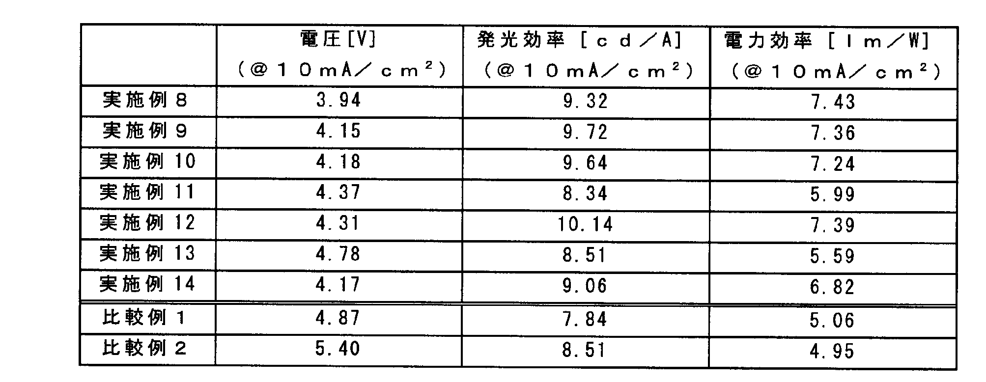
そこで、電子輸送層の化合物を、電子キャリアの輸送速度が速い材料であるアントラセン環構造とピリドインドール環構造を有する化合物(化合物2-1、化合物2-2、化合物1-6、化合物1-11、化合物1-15、化合物1-17、化合物1-18)に代えたところ、実施例8~14に示すように、駆動電圧のさらなる低下と電流効率および電力効率の大幅な向上が確認できた。これは、正孔の移動度が高い材料と電子キャリアの輸送速度が速い材料を組み合わせることにより、正孔キャリアと電子キャリアのキャリアバランスが改善されたことを示している。 From Comparative Example 1 and Comparative Example 2, it was confirmed that when the compound of the hole injection layer was changed from CuPc to Compound 3-1, the driving voltage was lowered but the luminous efficiency was lowered. This was thought to be because the hole mobility of compound 3-1 was too high, hole carriers increased, the carrier balance was lost, and the recombination probability decreased.
Therefore, the compound of the electron transport layer is changed to a compound having an anthracene ring structure and a pyridoindole ring structure (compound 2-1, compound 2-2, compound 1-6, compound 1-6) which is a material having a high electron carrier transport rate. 11 and compound 1-15, compound 1-17, and compound 1-18), as shown in Examples 8 to 14, it was confirmed that the drive voltage was further lowered and the current efficiency and the power efficiency were greatly improved. It was. This indicates that the carrier balance between the hole carrier and the electron carrier is improved by combining a material having a high hole mobility and a material having a high electron carrier transport speed.
2:透明陽極
3:正孔注入層
4:正孔輸送層
5:発光層
6:電子輸送層
7:電子注入層
8:陰極 1: Glass substrate 2: Transparent anode 3: Hole injection layer 4: Hole transport layer 5: Light emitting layer 6: Electron transport layer 7: Electron injection layer 8: Cathode
Claims (15)
- 陽極と陰極との間に、正孔注入層、正孔輸送層、発光層及び電子輸送層が設けられている有機エレクトロルミネッセンス素子において、
前記正孔注入層が、3個以上のトリフェニルアミン骨格が単結合または2価の炭化水素基で結合されている分子構造を有するアリールアミン化合物(α)を含み、
前記正孔輸送層が、2個のトリフェニルアミン骨格が単結合または2価の炭化水素基で結合されている分子構造を有するアリールアミン化合物(β)を含み、
前記電子輸送層が、下記一般式(1)または下記一般式(2)で表されるアントラセン環骨格とピリドインドール環骨格を有する電子輸送性化合物を含有すること、
を特徴とする有機エレクトロルミネッセンス素子;

pは、2価の基Aの数を示し、0~4の整数であり、
Aは、2価の無置換または置換芳香族炭化水素環基もしくは芳
香族複素環基を示し、但し、pが2以上であるとき、複数のAは
互いに異なっていてよく、pが0であるときは、Aは存在せず、
アントラセン環とピリドインドール環とが単結合を介して結合し
ているものとし、
Ar1は、無置換または置換芳香族炭化水素基もしくは芳香族
複素環基を示し、
Ar2は、無置換または置換芳香族炭化水素基を示し、
R1~R7は、それぞれ、水素原子、重水素原子、フッ素原子
、塩素原子、シアノ基、トリフルオロメチル基、炭素原子数1な
いし6の無置換アルキル基、無置換または置換芳香族炭化水素基
もしくは芳香族複素環基を表し、
R8の数を示すr8は、0~8の整数を表し、
R8は、重水素原子、フッ素原子、塩素原子、シアノ基、トリ
フルオロメチル基、または炭素原子数1ないし6の無置換アルキ
ル基を表し、r8が2以上の数であるとき複数のR8は互いに同
一でも異なっていてもよく、
W、X、Y及びZは、それぞれ、炭素原子または窒素原子を表
すが、そのいずれか1つのみが窒素原子であるものとし、この場
合の窒素原子にはR1~R4が結合していないものとする、

qは、2価の基Bの数を示し、0~4の整数であり、
Bは、2価の無置換または置換芳香族炭化水素環基もしくは芳
香族複素環基を示し、但し、qが2以上であるとき、複数のBは
互いに異なっていてよく、qが0であるときは、Bは存在せず、
アントラセン環とピリドインドール環とが単結合を介して結合し
ているものとし、
Ar3は、無置換または置換芳香族炭化水素基もしくは芳香族
複素環基を示し、
Ar4及びAr5は、無置換または置換芳香族炭化水素基を示
し、
R9~R15は、それぞれ、水素原子、重水素原子、フッ素原
子、塩素原子、シアノ基、トリフルオロメチル基、炭素原子数
1ないし6の無置換アルキル基、無置換または置換芳香族炭化
水素基もしくは芳香族複素環基を表し、
R16の数を示すr16は、0~7の整数を表し、
R16は、重水素原子、フッ素原子、塩素原子、シアノ基、ト
リフルオロメチル基、または炭素原子数1ないし6の無置換ア
ルキル基を表し、r16が2以上の数であるとき、複数のR16は
互いに同一でも異なっていてもよく、
W、X、Y及びZは、それぞれ、炭素原子または窒素原子を表
すが、そのいずれか1つのみが窒素原子であるものとし、この場
合の窒素原子にはR9~R12が結合していないものとする。 In the organic electroluminescence device in which a hole injection layer, a hole transport layer, a light emitting layer and an electron transport layer are provided between the anode and the cathode,
The hole injection layer includes an arylamine compound (α) having a molecular structure in which three or more triphenylamine skeletons are bonded by a single bond or a divalent hydrocarbon group,
The hole transport layer includes an arylamine compound (β) having a molecular structure in which two triphenylamine skeletons are bonded by a single bond or a divalent hydrocarbon group;
The electron transport layer contains an electron transport compound having an anthracene ring skeleton and a pyridoindole ring skeleton represented by the following general formula (1) or the following general formula (2);
An organic electroluminescence device characterized by:
p represents the number of divalent groups A and is an integer of 0 to 4,
A represents a divalent unsubstituted or substituted aromatic hydrocarbon ring group or aromatic heterocyclic group, provided that when p is 2 or more, a plurality of A may be different from each other, and p is 0. Sometimes there is no A,
It is assumed that the anthracene ring and the pyridoindole ring are bonded via a single bond,
Ar 1 represents an unsubstituted or substituted aromatic hydrocarbon group or aromatic heterocyclic group,
Ar 2 represents an unsubstituted or substituted aromatic hydrocarbon group,
R 1 to R 7 are each a hydrogen atom, a deuterium atom, a fluorine atom, a chlorine atom, a cyano group, a trifluoromethyl group, an unsubstituted alkyl group having 1 to 6 carbon atoms, an unsubstituted or substituted aromatic carbon Represents a hydrogen group or an aromatic heterocyclic group,
R 8 indicating the number of R 8 represents an integer of 0 to 8,
R 8 represents a deuterium atom, a fluorine atom, a chlorine atom, a cyano group, a trifluoromethyl group, or an unsubstituted alkyl group having 1 to 6 carbon atoms, and when r 8 is a number of 2 or more, R 8 may be the same or different from each other,
W, X, Y and Z each represent a carbon atom or a nitrogen atom, and only one of them is a nitrogen atom, and in this case, R 1 to R 4 are bonded to the nitrogen atom. Suppose you are not
q represents the number of divalent groups B and is an integer of 0 to 4,
B represents a divalent unsubstituted or substituted aromatic hydrocarbon ring group or aromatic heterocyclic group, provided that when q is 2 or more, a plurality of B may be different from each other, and q is 0; Sometimes, B doesn't exist,
It is assumed that the anthracene ring and the pyridoindole ring are bonded via a single bond,
Ar 3 represents an unsubstituted or substituted aromatic hydrocarbon group or aromatic heterocyclic group,
Ar 4 and Ar 5 represent an unsubstituted or substituted aromatic hydrocarbon group,
R 9 to R 15 are each a hydrogen atom, a deuterium atom, a fluorine atom, a chlorine atom, a cyano group, a trifluoromethyl group, an unsubstituted alkyl group having 1 to 6 carbon atoms, an unsubstituted or substituted aromatic carbonized carbon. Represents a hydrogen group or an aromatic heterocyclic group,
R 16 indicating the number of R 16 represents an integer of 0-7,
R 16 represents a deuterium atom, a fluorine atom, a chlorine atom, a cyano group, a trifluoromethyl group, or an unsubstituted alkyl group having 1 to 6 carbon atoms, and when r 16 is a number of 2 or more, a plurality of R 16 may be the same or different from each other,
W, X, Y, and Z each represent a carbon atom or a nitrogen atom, and only one of them is a nitrogen atom, and R 9 to R 12 are bonded to the nitrogen atom in this case. Suppose you have not. - 前記アリールアミン化合物(α)が、下記一般式(3)で表される請求項1記載の有機エレクトロルミネッセンス素子;

r17~r28は、それぞれR17~R28の数を示すもので
あり、これらの内、r17、r18、r21、r24、r27及
びr28は、0~5の整数を表し、r19、r20、r22、
r23、r25及びr26は、0~4の整数を表し、
R17~R28は、それぞれ、重水素原子、フッ素原子、塩素
原子、シアノ基、トリフルオロメチル基、炭素原子数1ないし6
の無置換アルキル基、炭素原子数2ないし6の無置換もしくは置
換アルケニル基、無置換または置換芳香族炭化水素基もしくは芳
香族複素環基であり、これらの基の中で同一のベンゼン環に結合
しているもの同士は、互いに結合して環を形成していてもよく、
E1~E3は、それぞれ、単結合或いは下記式;

n1は、1~3の整数を表し、
R29、R30及びR31の数を示すr29、r30、r31
は、それぞれ、0~4の整数を表し、
R29、R30及びR31は、それぞれ、前記R17~R28
と同様の原子もしくは基を示す、
の何れかで表される2価の基を表す。 The organic electroluminescence device according to claim 1, wherein the arylamine compound (α) is represented by the following general formula (3);
r 17 to r 28 each represent the number of R 17 to R 28 , and of these, r 17 , r 18 , r 21 , r 24 , r 27 and r 28 are integers of 0 to 5 R 19 , r 20 , r 22 ,
r 23 , r 25 and r 26 represent an integer of 0 to 4,
R 17 to R 28 are each a deuterium atom, a fluorine atom, a chlorine atom, a cyano group, a trifluoromethyl group, or 1 to 6 carbon atoms.
An unsubstituted alkyl group, an unsubstituted or substituted alkenyl group having 2 to 6 carbon atoms, an unsubstituted or substituted aromatic hydrocarbon group or an aromatic heterocyclic group, and among these groups, the same benzene ring Those bonded to each other may be bonded to each other to form a ring,
E 1 to E 3 are each a single bond or the following formula:
n1 represents an integer of 1 to 3,
R 29 indicating the number of R 29, R 30 and R 31, r 30, r 31
Each represents an integer from 0 to 4,
R 29 , R 30 and R 31 are respectively R 17 to R 28.
Represents the same atom or group as
It represents a divalent group represented by any of the above. - 前記アリールアミン化合物(β)が、下記一般式(4)で表される請求項1に記載の有機エレクトロルミネッセンス素子;

R32~R37の数を示すr32~r37において、r32、
r33、r36、r37は、0~5の整数を表し、r34、
r35は0~4の整数を表し、
R32~R37は、それぞれ、重水素原子、フッ素原子、塩素
原子、シアノ基、トリフルオロメチル基、炭素原子数1ないし6
の無置換アルキル基、炭素原子数2ないし6の無置換もしくは置
換アルケニル基、無置換または置換芳香族炭化水素基もしくは芳
香族複素環基であり、これらの基の中で同一のベンゼン環に結合
しているもの同士は、互いに結合して環を形成していてもよく、
E4は、単結合或いは下記式;

n1は、1~3の整数を表し、
R29、R30及びR31の数を示すr29、r30、r31
は、それぞれ、0~4の整数を表し、
R29、R30及びR31は、それぞれ、前記R17~R28
と同様の原子もしくは基を示す、
の何れかで表される2価の基を表す。 The organic electroluminescence device according to claim 1, wherein the arylamine compound (β) is represented by the following general formula (4);
In r 32 to r 37 indicating the number of R 32 to R 37 , r 32 ,
r 33 , r 36 and r 37 each represents an integer of 0 to 5, r 34 ,
r 35 represents an integer of 0 to 4,
R 32 to R 37 are each a deuterium atom, a fluorine atom, a chlorine atom, a cyano group, a trifluoromethyl group, or 1 to 6 carbon atoms.
An unsubstituted alkyl group, an unsubstituted or substituted alkenyl group having 2 to 6 carbon atoms, an unsubstituted or substituted aromatic hydrocarbon group or an aromatic heterocyclic group, and among these groups, the same benzene ring Those bonded to each other may be bonded to each other to form a ring,
E 4 represents a single bond or the following formula:
n1 represents an integer of 1 to 3,
R 29 indicating the number of R 29, R 30 and R 31, r 30, r 31
Each represents an integer from 0 to 4,
R 29 , R 30 and R 31 are respectively R 17 to R 28.
Represents the same atom or group as
It represents a divalent group represented by any of the above. - 前記電子輸送性化合物が、下記一般式(1a):

A、Ar1、Ar2、R1~R8、p及びr8、W、X、Y及
びZは、前記一般式(1)で記載したとおりである、
で表される請求項1記載の有機エレクトロルミネッセンス素子。 The electron transporting compound is represented by the following general formula (1a):
A, Ar 1, Ar 2, R 1 ~ R 8, p and r 8, W, X, Y及Beauty Z are as described in Formula (1),
The organic electroluminescent element of Claim 1 represented by these. - 前記電子輸送性化合物が、下記一般式(1b):
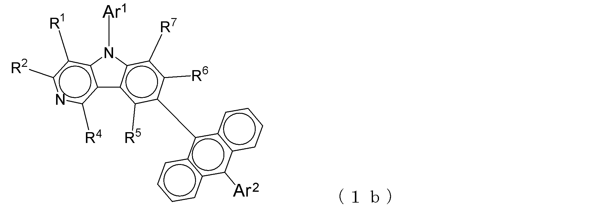
Ar1、Ar2、R1、R2、R4~R7は、前記一般式
(1)で記載したとおりである、
で表される請求項4に記載の有機エレクトロルミネッセンス素子。 The electron transporting compound is represented by the following general formula (1b):
Ar 1 , Ar 2 , R 1 , R 2 , R 4 to R 7 are as described in the general formula (1).
The organic electroluminescent element of Claim 4 represented by these. - 前記電子輸送性化合物が、下記一般式(1c):

Ar1、Ar2、R1、R2、R4~R7は、前記一般式
(1)で記載したとおりである、
で表される請求項4に記載の有機エレクトロルミネッセンス素子。 The electron transporting compound is represented by the following general formula (1c):
Ar 1 , Ar 2 , R 1 , R 2 , R 4 to R 7 are as described in the general formula (1).
The organic electroluminescent element of Claim 4 represented by these. - 前記電子輸送性化合物が、下記一般式(1d):

Ar1、Ar2、R1、R2、R4~R7は、前記一般式
(1)で記載したとおりである、
で表される請求項4に記載の有機エレクトロルミネッセンス素子。 The electron transporting compound is represented by the following general formula (1d):
Ar 1 , Ar 2 , R 1 , R 2 , R 4 to R 7 are as described in the general formula (1).
The organic electroluminescent element of Claim 4 represented by these. - 前記電子輸送性化合物が、下記一般式(1e):
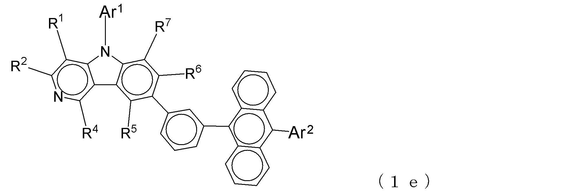
Ar1、Ar2、R1、R2、R4~R7は、前記一般式
(1)で記載したとおりである、
で表される請求項4に記載の有機エレクトロルミネッセンス素子。 The electron transporting compound is represented by the following general formula (1e):
Ar 1 , Ar 2 , R 1 , R 2 , R 4 to R 7 are as described in the general formula (1).
The organic electroluminescent element of Claim 4 represented by these. - 前記電子輸送性化合物が、下記一般式(1f):

Ar1、Ar2、R1、R2、R4~R7は、前記一般式
(1)で記載したとおりである、
で表される請求項4に記載の有機エレクトロルミネッセンス素子。 The electron transporting compound is represented by the following general formula (1f):
Ar 1 , Ar 2 , R 1 , R 2 , R 4 to R 7 are as described in the general formula (1).
The organic electroluminescent element of Claim 4 represented by these. - 前記電子輸送性化合物が、下記一般式(1g):

Ar1、Ar2、R1、R2、R4~R7は、前記一般式
(1)で記載したとおりである、
で表される請求項4に記載の有機エレクトロルミネッセンス素子。 The electron transporting compound has the following general formula (1 g):
Ar 1, Ar 2, R 1 , R 2, R 4 ~ R 7 are as described in Formula (1),
The organic electroluminescent element of Claim 4 represented by these. - 前記電子輸送性化合物が、下記一般式(2a):

B、Ar3~Ar5、R9~R16、q及びr16、W、X、
Y及びZは、前記一般式(2)で記載したとおりである、
で表される請求項1記載の有機エレクトロルミネッセンス素子。 The electron transporting compound is represented by the following general formula (2a):
B, Ar 3 to Ar 5 , R 9 to R 16 , q and r 16 , W, X,
Y and Z are as described in the general formula (2).
The organic electroluminescent element of Claim 1 represented by these. - 前記電子輸送性化合物が、下記一般式(2b):

B、Ar3~Ar5、R9~R16、q及びr16、W、X、
Y及びZは、前記一般式(2)で記載したとおりである、
で表される請求項11記載の有機エレクトロルミネッセンス素子。 The electron transporting compound is represented by the following general formula (2b):
B, Ar 3 to Ar 5 , R 9 to R 16 , q and r 16 , W, X,
Y and Z are as described in the general formula (2).
The organic electroluminescent element of Claim 11 represented by these. - 前記電子輸送性化合物が、下記一般式(2c):

Ar3~Ar5、R9、R10、R12~R15は、前記一般
式(2)で記載したとおりである、
で表される請求項12記載の有機エレクトロルミネッセンス素子。 The electron transporting compound is represented by the following general formula (2c):
Ar 3 to Ar 5 , R 9 , R 10 , R 12 to R 15 are as described in the general formula (2).
The organic electroluminescent element of Claim 12 represented by these. - 前記電子輸送性化合物が、下記一般式(2d):
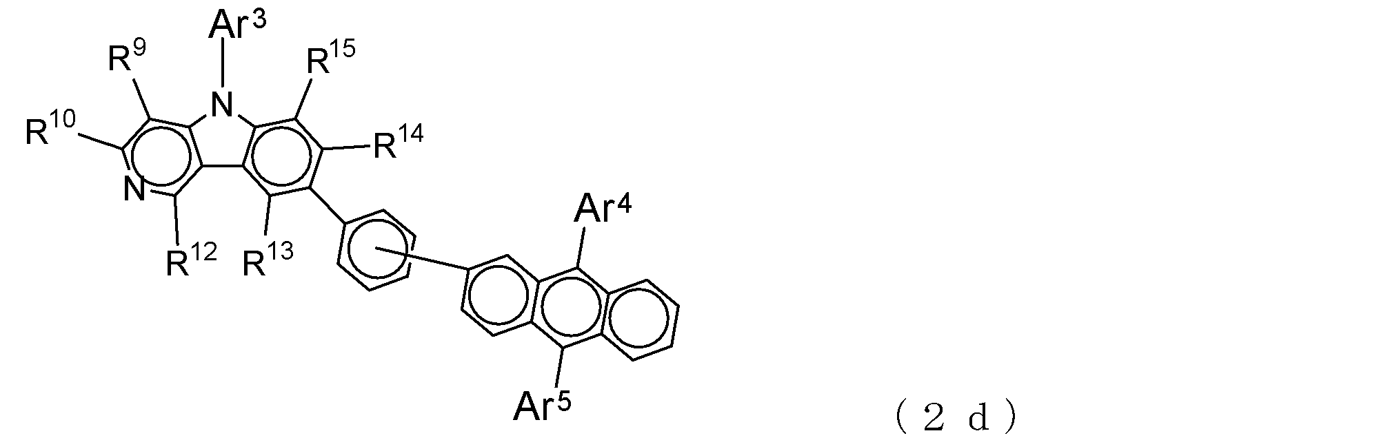
Ar3~Ar5、R9、R10、R12~R15は、前記一般
式(2)で記載したとおりである、
で表される請求項12記載の有機エレクトロルミネッセンス素子。 The electron transporting compound is represented by the following general formula (2d):
Ar 3 to Ar 5 , R 9 , R 10 , R 12 to R 15 are as described in the general formula (2).
The organic electroluminescent element of Claim 12 represented by these. - 前記電子輸送性化合物が、下記一般式(2e):
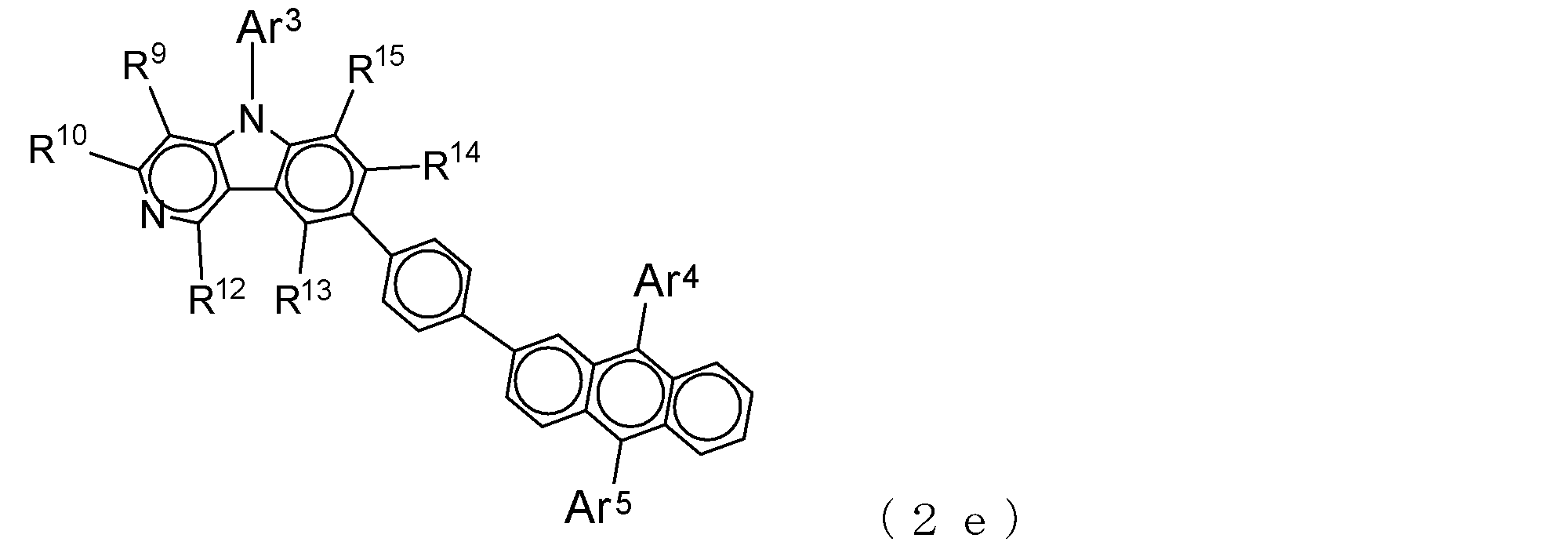
Ar3~Ar5、R9、R10、R12~R15は、前記一般
式(2)で記載したとおりである、
で表される請求項12記載の有機エレクトロルミネッセンス素子。 The electron transporting compound is represented by the following general formula (2e):
Ar 3 to Ar 5 , R 9 , R 10 , R 12 to R 15 are as described in the general formula (2).
The organic electroluminescent element of Claim 12 represented by these.
Priority Applications (6)
| Application Number | Priority Date | Filing Date | Title |
|---|---|---|---|
| EP16001777.8A EP3133665B1 (en) | 2011-04-25 | 2012-04-17 | Organic electroluminescent device |
| JP2013512023A JP6058531B2 (en) | 2011-04-25 | 2012-04-17 | Organic electroluminescence device |
| KR1020137028140A KR101998430B1 (en) | 2011-04-25 | 2012-04-17 | Organic electroluminescent element |
| CN201280019976.2A CN103493239A (en) | 2011-04-25 | 2012-04-17 | Organic electroluminescent element |
| US14/008,708 US9553272B2 (en) | 2011-04-25 | 2012-04-17 | Organic electroluminescent device |
| EP12775988.4A EP2704225B1 (en) | 2011-04-25 | 2012-04-17 | Organic electroluminescent element |
Applications Claiming Priority (2)
| Application Number | Priority Date | Filing Date | Title |
|---|---|---|---|
| JP2011096744 | 2011-04-25 | ||
| JP2011-096744 | 2011-04-25 |
Publications (1)
| Publication Number | Publication Date |
|---|---|
| WO2012147568A1 true WO2012147568A1 (en) | 2012-11-01 |
Family
ID=47072090
Family Applications (1)
| Application Number | Title | Priority Date | Filing Date |
|---|---|---|---|
| PCT/JP2012/060374 WO2012147568A1 (en) | 2011-04-25 | 2012-04-17 | Organic electroluminescent element |
Country Status (7)
| Country | Link |
|---|---|
| US (1) | US9553272B2 (en) |
| EP (2) | EP2704225B1 (en) |
| JP (1) | JP6058531B2 (en) |
| KR (1) | KR101998430B1 (en) |
| CN (1) | CN103493239A (en) |
| TW (1) | TW201308707A (en) |
| WO (1) | WO2012147568A1 (en) |
Families Citing this family (5)
| Publication number | Priority date | Publication date | Assignee | Title |
|---|---|---|---|---|
| JP6348113B2 (en) * | 2013-07-01 | 2018-06-27 | 出光興産株式会社 | COMPOUND, MATERIAL FOR ORGANIC ELECTROLUMINESCENT ELEMENT, ORGANIC ELECTROLUMINESCENT ELEMENT, AND ELECTRONIC DEVICE |
| WO2016017594A1 (en) * | 2014-07-29 | 2016-02-04 | 保土谷化学工業株式会社 | Organic electroluminescent element |
| KR102244800B1 (en) | 2017-12-11 | 2021-04-26 | 주식회사 엘지화학 | Organic light emitting device and method of manufacturing the same |
| US20210319957A1 (en) * | 2018-08-16 | 2021-10-14 | Tokyo Chemical Industry Co., Ltd. | Novel compound, and composition for forming hole transporting layer for perovskite solar cells |
| CN111470984B (en) * | 2020-04-16 | 2022-12-13 | 苏州欧谱科显示科技有限公司 | Hole transport material and preparation method and application thereof |
Citations (9)
| Publication number | Priority date | Publication date | Assignee | Title |
|---|---|---|---|---|
| US4720432A (en) | 1987-02-11 | 1988-01-19 | Eastman Kodak Company | Electroluminescent device with organic luminescent medium |
| JPH06314594A (en) | 1992-12-18 | 1994-11-08 | Ricoh Co Ltd | Organic thin film electroluminescent element having plural carrier injection layer |
| JPH08291115A (en) | 1995-04-21 | 1996-11-05 | Bando Chem Ind Ltd | New triphenylamine compound |
| JP3529735B2 (en) | 2001-02-23 | 2004-05-24 | 松下電器産業株式会社 | Electroluminescent device |
| US20090230857A1 (en) * | 2008-03-14 | 2009-09-17 | Byoung-Ki Choi | Aromatic heterocyclic compound, organic light emitting diode comprising organic layer comprising the same and method of manufacturing the organic light emitting diode |
| WO2009139475A1 (en) * | 2008-05-16 | 2009-11-19 | 保土谷化学工業株式会社 | Organic electroluminescent device |
| WO2010035723A1 (en) * | 2008-09-24 | 2010-04-01 | 保土谷化学工業株式会社 | Compound having substituted anthracene ring structure and pyridoindole ring structure and organic electroluminescence device |
| WO2010114256A2 (en) * | 2009-03-31 | 2010-10-07 | Dow Advanced Display Materials,Ltd. | Novel organic electroluminescent compounds and organic electroluminescent device using the same |
| WO2011059000A1 (en) * | 2009-11-12 | 2011-05-19 | 保土谷化学工業株式会社 | Compound having a substituted anthracene ring structure and pyridoindole ring structure, and organic electroluminescent element |
Family Cites Families (8)
| Publication number | Priority date | Publication date | Assignee | Title |
|---|---|---|---|---|
| JPS529735A (en) | 1975-07-11 | 1977-01-25 | Hitachi Ltd | Pinion stopper device for starter |
| KR101411135B1 (en) * | 2006-08-18 | 2014-06-23 | 호도가야 가가쿠 고교 가부시키가이샤 | Compound having pyridoindole ring structure having substituted pyridyl group attached thereto, and organic electroluminescence element |
| KR100903203B1 (en) | 2006-11-30 | 2009-06-18 | 에스에프씨 주식회사 | Anthracene derivative and organoelectroluminescent device employing the same |
| JP2009209127A (en) * | 2008-02-08 | 2009-09-17 | Toyo Ink Mfg Co Ltd | Compound having carbazolyl group and use thereof |
| KR101513870B1 (en) * | 2008-03-14 | 2015-04-23 | 삼성디스플레이 주식회사 | An aromatic heterocyclic compound an organic light emitting diode comprising an organic layer comprising the same and an method for preparing the organic light emitting diode |
| CN104910064A (en) * | 2008-04-24 | 2015-09-16 | 株式会社半导体能源研究所 | Anthracene derivative, light-emitting element, light-emitting device, and electronic appliance |
| US8716698B2 (en) * | 2008-06-11 | 2014-05-06 | Hodogaya Chemical Co., Ltd. | Organic electroluminescent device containing arylamine compound and bipyridyl compound |
| CN103403909A (en) | 2011-02-28 | 2013-11-20 | 保土谷化学工业株式会社 | Organic electroluminescent element |
-
2012
- 2012-04-17 KR KR1020137028140A patent/KR101998430B1/en active IP Right Grant
- 2012-04-17 US US14/008,708 patent/US9553272B2/en active Active
- 2012-04-17 JP JP2013512023A patent/JP6058531B2/en active Active
- 2012-04-17 WO PCT/JP2012/060374 patent/WO2012147568A1/en active Application Filing
- 2012-04-17 EP EP12775988.4A patent/EP2704225B1/en active Active
- 2012-04-17 CN CN201280019976.2A patent/CN103493239A/en active Pending
- 2012-04-17 EP EP16001777.8A patent/EP3133665B1/en active Active
- 2012-04-24 TW TW101114551A patent/TW201308707A/en unknown
Patent Citations (9)
| Publication number | Priority date | Publication date | Assignee | Title |
|---|---|---|---|---|
| US4720432A (en) | 1987-02-11 | 1988-01-19 | Eastman Kodak Company | Electroluminescent device with organic luminescent medium |
| JPH06314594A (en) | 1992-12-18 | 1994-11-08 | Ricoh Co Ltd | Organic thin film electroluminescent element having plural carrier injection layer |
| JPH08291115A (en) | 1995-04-21 | 1996-11-05 | Bando Chem Ind Ltd | New triphenylamine compound |
| JP3529735B2 (en) | 2001-02-23 | 2004-05-24 | 松下電器産業株式会社 | Electroluminescent device |
| US20090230857A1 (en) * | 2008-03-14 | 2009-09-17 | Byoung-Ki Choi | Aromatic heterocyclic compound, organic light emitting diode comprising organic layer comprising the same and method of manufacturing the organic light emitting diode |
| WO2009139475A1 (en) * | 2008-05-16 | 2009-11-19 | 保土谷化学工業株式会社 | Organic electroluminescent device |
| WO2010035723A1 (en) * | 2008-09-24 | 2010-04-01 | 保土谷化学工業株式会社 | Compound having substituted anthracene ring structure and pyridoindole ring structure and organic electroluminescence device |
| WO2010114256A2 (en) * | 2009-03-31 | 2010-10-07 | Dow Advanced Display Materials,Ltd. | Novel organic electroluminescent compounds and organic electroluminescent device using the same |
| WO2011059000A1 (en) * | 2009-11-12 | 2011-05-19 | 保土谷化学工業株式会社 | Compound having a substituted anthracene ring structure and pyridoindole ring structure, and organic electroluminescent element |
Non-Patent Citations (3)
| Title |
|---|
| J. CHEM. SOC., PERKIN TRANS., vol. 1, 1999, pages 1505 |
| J. ORG. CHEM., vol. 60, 1995, pages 7508 |
| See also references of EP2704225A4 |
Also Published As
| Publication number | Publication date |
|---|---|
| US9553272B2 (en) | 2017-01-24 |
| EP2704225A1 (en) | 2014-03-05 |
| US20140021451A1 (en) | 2014-01-23 |
| EP2704225B1 (en) | 2019-02-06 |
| EP3133665A1 (en) | 2017-02-22 |
| EP3133665B1 (en) | 2020-03-04 |
| KR101998430B1 (en) | 2019-10-17 |
| JPWO2012147568A1 (en) | 2014-07-28 |
| TW201308707A (en) | 2013-02-16 |
| EP2704225A4 (en) | 2016-02-24 |
| CN103493239A (en) | 2014-01-01 |
| JP6058531B2 (en) | 2017-01-11 |
| KR20140027963A (en) | 2014-03-07 |
Similar Documents
| Publication | Publication Date | Title |
|---|---|---|
| JP5719308B2 (en) | Compounds having substituted anthracene ring structure and pyridoindole ring structure and organic electroluminescence device | |
| KR101964435B1 (en) | Hetero-cyclic compound and organic light emitting device comprising the same | |
| JP6184867B2 (en) | Novel benzotriazole derivative and organic electroluminescent device using the derivative | |
| WO2011105373A1 (en) | Substituted pyridyl compound and organic electroluminescent element | |
| JPWO2014087657A1 (en) | Aromatic amine derivative and organic electroluminescence device | |
| JP6182217B2 (en) | COMPOUND, MATERIAL FOR ORGANIC ELECTROLUMINESCENT ELEMENT, ORGANIC ELECTROLUMINESCENT ELEMENT AND ELECTRONIC DEVICE | |
| JP6301919B2 (en) | Novel pyrimidine derivatives and organic electroluminescence devices | |
| JP5683763B1 (en) | Benzopyridindole derivatives and organic electroluminescence devices | |
| JP6058531B2 (en) | Organic electroluminescence device | |
| JP2023525021A (en) | Novel compound and organic light-emitting device using the same | |
| KR20190084855A (en) | Hetero-cyclic compound and organic light emitting device comprising the same | |
| KR20180066855A (en) | Novel amine-based compound and organic light emitting device comprising the same | |
| KR101994448B1 (en) | Novel hetero-cyclic compound and organic light emitting device comprising the same | |
| JP6301729B2 (en) | Compound having indoloquinoxaline ring structure and organic electroluminescence device | |
| JP6389461B2 (en) | Benzotriazole derivatives and organic electroluminescence devices | |
| TW202030307A (en) | Heterocyclic compound and organic light emitting device comprising the same | |
| EP2679582A1 (en) | Compound containing substituted o-terphenyl structure, and organic electroluminescent element | |
| JP6479770B2 (en) | Quinolininotriazole derivatives and organic electroluminescence devices | |
| WO2019039402A1 (en) | Compound having indenobenzoazole-ring structure, and organic electroluminescence element |
Legal Events
| Date | Code | Title | Description |
|---|---|---|---|
| 121 | Ep: the epo has been informed by wipo that ep was designated in this application |
Ref document number: 12775988 Country of ref document: EP Kind code of ref document: A1 |
|
| ENP | Entry into the national phase |
Ref document number: 2013512023 Country of ref document: JP Kind code of ref document: A |
|
| WWE | Wipo information: entry into national phase |
Ref document number: 2012775988 Country of ref document: EP |
|
| WWE | Wipo information: entry into national phase |
Ref document number: 14008708 Country of ref document: US |
|
| ENP | Entry into the national phase |
Ref document number: 20137028140 Country of ref document: KR Kind code of ref document: A |
|
| NENP | Non-entry into the national phase |
Ref country code: DE |