WO2012036298A1 - Bone resection jig used in surgical operation to replace artificial knee joint - Google Patents
Bone resection jig used in surgical operation to replace artificial knee joint Download PDFInfo
- Publication number
- WO2012036298A1 WO2012036298A1 PCT/JP2011/071537 JP2011071537W WO2012036298A1 WO 2012036298 A1 WO2012036298 A1 WO 2012036298A1 JP 2011071537 W JP2011071537 W JP 2011071537W WO 2012036298 A1 WO2012036298 A1 WO 2012036298A1
- Authority
- WO
- WIPO (PCT)
- Prior art keywords
- femur
- resection
- knee joint
- distal end
- reference pin
- Prior art date
Links
Images


Classifications
-
- A—HUMAN NECESSITIES
- A61—MEDICAL OR VETERINARY SCIENCE; HYGIENE
- A61B—DIAGNOSIS; SURGERY; IDENTIFICATION
- A61B17/00—Surgical instruments, devices or methods, e.g. tourniquets
- A61B17/16—Bone cutting, breaking or removal means other than saws, e.g. Osteoclasts; Drills or chisels for bones; Trepans
- A61B17/17—Guides or aligning means for drills, mills, pins or wires
- A61B17/1739—Guides or aligning means for drills, mills, pins or wires specially adapted for particular parts of the body
- A61B17/1764—Guides or aligning means for drills, mills, pins or wires specially adapted for particular parts of the body for the knee
-
- A—HUMAN NECESSITIES
- A61—MEDICAL OR VETERINARY SCIENCE; HYGIENE
- A61B—DIAGNOSIS; SURGERY; IDENTIFICATION
- A61B17/00—Surgical instruments, devices or methods, e.g. tourniquets
- A61B17/02—Surgical instruments, devices or methods, e.g. tourniquets for holding wounds open; Tractors
- A61B17/025—Joint distractors
-
- A—HUMAN NECESSITIES
- A61—MEDICAL OR VETERINARY SCIENCE; HYGIENE
- A61B—DIAGNOSIS; SURGERY; IDENTIFICATION
- A61B17/00—Surgical instruments, devices or methods, e.g. tourniquets
- A61B17/14—Surgical saws ; Accessories therefor
- A61B17/15—Guides therefor
- A61B17/154—Guides therefor for preparing bone for knee prosthesis
- A61B17/155—Cutting femur
-
- A—HUMAN NECESSITIES
- A61—MEDICAL OR VETERINARY SCIENCE; HYGIENE
- A61F—FILTERS IMPLANTABLE INTO BLOOD VESSELS; PROSTHESES; DEVICES PROVIDING PATENCY TO, OR PREVENTING COLLAPSING OF, TUBULAR STRUCTURES OF THE BODY, e.g. STENTS; ORTHOPAEDIC, NURSING OR CONTRACEPTIVE DEVICES; FOMENTATION; TREATMENT OR PROTECTION OF EYES OR EARS; BANDAGES, DRESSINGS OR ABSORBENT PADS; FIRST-AID KITS
- A61F2/00—Filters implantable into blood vessels; Prostheses, i.e. artificial substitutes or replacements for parts of the body; Appliances for connecting them with the body; Devices providing patency to, or preventing collapsing of, tubular structures of the body, e.g. stents
- A61F2/02—Prostheses implantable into the body
- A61F2/30—Joints
- A61F2/46—Special tools or methods for implanting or extracting artificial joints, accessories, bone grafts or substitutes, or particular adaptations therefor
- A61F2/4684—Trial or dummy prostheses
-
- A—HUMAN NECESSITIES
- A61—MEDICAL OR VETERINARY SCIENCE; HYGIENE
- A61B—DIAGNOSIS; SURGERY; IDENTIFICATION
- A61B17/00—Surgical instruments, devices or methods, e.g. tourniquets
- A61B17/02—Surgical instruments, devices or methods, e.g. tourniquets for holding wounds open; Tractors
- A61B17/025—Joint distractors
- A61B2017/0268—Joint distractors for the knee
-
- A—HUMAN NECESSITIES
- A61—MEDICAL OR VETERINARY SCIENCE; HYGIENE
- A61F—FILTERS IMPLANTABLE INTO BLOOD VESSELS; PROSTHESES; DEVICES PROVIDING PATENCY TO, OR PREVENTING COLLAPSING OF, TUBULAR STRUCTURES OF THE BODY, e.g. STENTS; ORTHOPAEDIC, NURSING OR CONTRACEPTIVE DEVICES; FOMENTATION; TREATMENT OR PROTECTION OF EYES OR EARS; BANDAGES, DRESSINGS OR ABSORBENT PADS; FIRST-AID KITS
- A61F2/00—Filters implantable into blood vessels; Prostheses, i.e. artificial substitutes or replacements for parts of the body; Appliances for connecting them with the body; Devices providing patency to, or preventing collapsing of, tubular structures of the body, e.g. stents
- A61F2/02—Prostheses implantable into the body
- A61F2/30—Joints
- A61F2/38—Joints for elbows or knees
- A61F2/389—Tibial components
Definitions
- the present invention relates to a bone resection jig used during artificial knee joint replacement surgery.
- this artificial knee joint is composed of a combination of a femoral member having two inner and outer condyles, and a tibial member having a joint plate for receiving the two condyles in a rotatable manner. It is desirable that the artificial knee joint composed of these condyles and the joint plate move in the same manner as a living knee joint.
- the femur and the tibia are connected by a number of ligaments, and extension and flexion are caused by the tension and relaxation of these ligaments.
- tension it is preferable that the same tension force is generated in the extended position and the bent position, and it is required to move smoothly without pain in the bent position.
- Japanese people often sit straight, deep flexion is also required.
- Patent Document 1 proposes a bone resection jig that sets the bone resection range after confirming that the tension is the same in the extended position and the bent position.
- the invention of this prior art confirms (measures) the tension of the ligament in the extended position and the bent position, so that the operation is troublesome and takes a long operation time.
- the structure is complicated, and there are many movable parts and adjustment parts, and many operations that are complicated and require skill are required. In addition, it is heavy and expensive.
- the present invention proposes a bone resection tool based on the principle that the tension force of the ligament in the extended position and the bent position can be derived from the same tension force if the bone resection range (interval) is the same in both positions. It has a very simple structure and is inexpensive. In addition, skill is not required for operation, and the operation time can be shortened to reduce the burden on the patient.
- the distal end of the femur and the proximal end of the tibia are horizontally dissected in the extended position, and then the femur is in the bent position.
- This jig forms a hollow box with a vertical hole on the other end of the grip.
- a guide hole is formed to guide the reference pin that extends and contacts the resection surface of the distal end of the femur and is inserted from the front and inserted into the resection surface of the distal end of the femur
- the reference pin guide and spacer block leaving the reference pin After being removed from between the femur and tibia, it is inserted using the guide hole of the reference pin as a guide and abuts the resection surface at the distal end of the end of the femur to indicate the rear resection surface of the distal end of the femur
- the present invention provides a bone resection jig for use in artificial knee joint replacement surgery, characterized by comprising an aim provided with an index
- the axis of the grip described in claim 2 passes through the center of the reference spacer portion, and the position around the hollow box of the grip does not interfere with the patella tendon. 4.
- the means according to Item 4 wherein the guide holes are provided horizontally on the left and right sides, and the means according to Item 5, wherein the indicator portion is a through-hole formed in the aim at various levels and angles.
- a means is provided for superimposing one or more additional spacers on the reference spacer portion described above to measure the distance between the distal ends of the femur and tibia resected in the extended position.
- main components are a spacer block inserted in the resection portion of the femur and tibia, a reference pin guide for accurately setting the bending position, and a distal portion of the femur Very little is required, consisting of an aim that sets the ablation range at the rear of the end, and the structure of each component is also simple. Therefore, the number of parts is small, the weight is low, the operation is simple, and skill is not required.
- the hollow box does not obstruct the field of view when the spacer block is inserted.
- the angle between the distal end and the rear end of the knee prosthesis can be adjusted to the shape of the femoral side member, and the femoral side member can be loaded accurately and reliably.
- the reference pin guide can be accurately set in a normal posture that is horizontal.
- the posterior portion of the distal end of the femur can be set at various levels and angles of the resection surface.
- the femur can be bent 90 ° while the reference spacer portion of the spacer block is inserted after the distal end of the femur and the proximal end of the tibia are excised by a predetermined amount.
- FIG. 1 is a perspective view of a spacer block 1 constituting a main part of a bone resection jig (hereinafter, referred to as a jig) used in an artificial knee joint replacement operation according to the present invention
- FIG. 2 is a plan view
- FIG. FIG. 2 is a perspective view of the reference pin guide 2 and the reference pin 3, and may refer to the front and rear, the top and bottom, and the left and right in the following, but this is based on a state in which the standing knee is viewed from the front and the outer side.
- the front part is the front face (patella side) of the knee
- the upper part is the femur side
- the left and right parts are the left knee if it is the left knee.
- the spacer block 1 is inserted into the resected portion of the resected distal end of the femur 4 and the proximal end of the tibia 5 and supports the reference pin guide 2. It consists of a hollow box 7 having a hole 7 a and a reference spacer portion 8.
- the grip 6 is a handle held by the practitioner, and a plurality of vertical holes 6a for alignment with the lower limbs are provided at the center.
- the vertical hole 7a of the hollow box 7 is for inserting the reference pin guide 2, and is formed in a square hole so that the reference pin guide 2 does not rotate.
- the reference pin guide 2 is supported by inserting a leg 2a into the longitudinal hole 7a, and the end of the distal end of the femur 4 is bent by 90 ° with respect to the end of the proximal end of the tibia 5 At the same time, it serves as a guide for inserting the reference pin 3, and a guide hole 9 is formed therefor.
- the axis 6 of the grip 6 passes through the center of the reference spacer portion 8, but the hollow box 7 is set immediately before the knee joint in order to improve aiming of the aim, which will be described later, attached to the grip box 6.
- the grip 6 has a hollow box 7 around the patella tendon so as to hold the patella tendon at a position that does not interfere with visual observation or operation (the patella tendon is held eccentrically outside).
- the reference pin guide 2 is eccentric to the axis side with respect to the leg 2a, and the reference pin guide 2 faces the reference spacer portion 8 when the leg 2a is inserted into the vertical hole 7a.
- a notch 8a is formed at the tip of the reference spacer 8 (the rear from the knee).
- the reference pin 3 is a pin that is inserted into the guide hole 9 of the reference pin guide 2 and inserted into the resection surface of the distal end 4 a of the femur 4.
- the fixing screw 10 which clamps the leg 2a of the reference pin guide 2 is attached to the hollow box 7, it goes without saying that the hollow box 7 and the fixing screw 10 are installed in front of the tibial 5. .
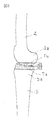
- the knee joint is approximately 180 ° in the extended position (FIG. 4).
- the end portion of the distal end 4a of the femur 4 is excised only by A (FIG. 5). This A is determined by the practitioner in consideration of the degree of damage, age, physique and the like.
- the end of the proximal end 5a of the tibia 5 is excised only by B (FIG. 6). This B depends on the degree of damage, but the B of the artificial knee joint to be loaded in relation to A It is also based on shape and size.
- the resection interval C between the femur 4 side and the tibia 5 side is measured based on the thickness. Whether to apply the artificial knee joint is determined (FIG. 9).
- the reason why the additional spacers are overlapped is that the reference spacer portion 8 alone is insufficient in thickness for the reason described later. If this can be confirmed, the additional spacer 11 is removed, and the femur 4 is brought into the bent position (FIG. 10).
- the reason for removing the additional spacer 11 is that the rear part 4a of the femur 4 is thick at the rear, and the femur 4 cannot be bent when it is attached.
- the reference spacer portion 8 has such a thickness that it can be inserted with a margin in the resection interval C between the femur 4 side and the tibia 5 side, the femur 4 can be bent when removed. Then, the reference pin guide 2 is inserted from above into the vertical hole 7a of the spacer block 1, to the rear surface 2b is in contact with the resected surface F H of the end portion of the distal end of the femur 4 ( Figure 11). This is because the femur 4 is bent at 90 ° with respect to the tibia 5. The bending angle may be 90 ° or more so that deep bending is possible.
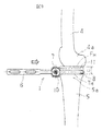
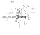
- the angle between the leg 2a and the rear surface 2b of the reference pin guide 2 is set in accordance with this angle. If the above can be set, the reference pin guide 2 is pulled upward while the reference pin 3 remains, and the spacer block 1 is pulled forward (FIG. 12). Then, an aim (sighting device) 12 is inserted into the reference pin 3 from the front (FIG. 13).
- the aim 12 has a frontal viewing angle (FIG. 14), a guide hole 13 into which the reference pin 3 can be inserted is formed, and the rear surface 2b is flat. This surface is formed on the distal end 4a of the femur 4. It abuts the resected surface F H end.
- the aim 12 indicator section 14 which indicates the rear part of the resected surface F R is the next excision site of the distal end 4a of the femur 4 is formed.
- the indicator portion 14 is a small through hole or a horizontally long through hole (slit) into which a cutter, a marking needle, a gauge, a drill, or the like enters. Therefore, this insert a cutter or the like into the slit 14, marks the line as a resected surface F R which is set in advance to a rear portion of the distal end 4a of the femur 4. Then, when cutting the rear and the mark as a reference, the rear is cut at cut surfaces F R.
- the aim 12 is also formed with a slit 15 that serves as an index for cutting the front portion of the distal end 4a of the femur 4 which is the next resection site. That is, holes or oblong holes as described above on top of aim 12 Yes forms, marked here in line to be resected surface F F of the front portion of the distal end 4 by inserting the cutter or the like. The excised with resection plane F F along the mark.
- each resections F H, F F, slits 16 formed of upper and hole or the like formed obliquely downward to the chamfered corner of F R is also formed, to which a mark When the corner is cut, the bone is cut into the polygonal shape shown in FIG. This chamfering is for improving the loadability of the femoral member.
- the femoral member and tibial member are loaded and the operation is completed, but various shapes and sizes are selected for the femoral member and tibial member in consideration of the degree of damage, age, physique, etc. Is as described above.
- the above is the replacement of the artificial joint of the right knee, but in the case of the left knee, the spacer block 1 may be inverted and used.
Landscapes
- Health & Medical Sciences (AREA)
- Life Sciences & Earth Sciences (AREA)
- Surgery (AREA)
- General Health & Medical Sciences (AREA)
- Heart & Thoracic Surgery (AREA)
- Veterinary Medicine (AREA)
- Public Health (AREA)
- Orthopedic Medicine & Surgery (AREA)
- Animal Behavior & Ethology (AREA)
- Engineering & Computer Science (AREA)
- Biomedical Technology (AREA)
- Medical Informatics (AREA)
- Molecular Biology (AREA)
- Nuclear Medicine, Radiotherapy & Molecular Imaging (AREA)
- Oral & Maxillofacial Surgery (AREA)
- Transplantation (AREA)
- Dentistry (AREA)
- Physical Education & Sports Medicine (AREA)
- Cardiology (AREA)
- Vascular Medicine (AREA)
- Surgical Instruments (AREA)
- Prostheses (AREA)
Abstract
Provided is a bone resection jig that can make ligament tension equal at extending and bending positions without any actual measurements when the femur and the tibia are resected during a surgical operation to replace an artificial knee joint. The bone resection jig which is used in a surgical operation to replace an artificial knee joint comprises a spacer block (1), a reference pin guide (2), and an aiming part (12). The spacer block (1) comprises: a hollow box (7) that includes a vertical hole (7a) at the other end of a grip (6); and a reference spacer (8) that extends from the hollow box (7) and is inserted into a resection region between the femur and the tibia. The reference pin guide (2) comprises a guide hole (9) for guiding a reference pin (3). In the bending position when the knee bends, the reference pin (3) is inserted into the vertical hole (7a) and extends on the reference spacer (8) to the other end side to make contact with a resection surface (FH) of the distal end part of the femur, and the reference pin (3) is implanted in the resection surface (FH) of the distal end part of the femur from the front side. The aiming part (12) comprises an index part (14). After the spacer block (1) is removed from between the femur and the tibia with the reference pin (3) remaining, the index part (14) is inserted into a guide hole (13) of the reference pin (3) with the guide hole (13) guiding the index part (14), and the index part (14) comes into contact with the resection surface (FH) at the distal end of the end part of the femur so as to indicate a resection surface (FR) of the rear part at the distal end of the femur.
Description
本発明は、人工膝関節置換手術時に使用される骨切除治具に関するものである。
The present invention relates to a bone resection jig used during artificial knee joint replacement surgery.
膝関節が変形性膝関節症、関節リウマチ、骨腫瘍を罹患したり、外傷等を負った場合には、大腿骨と脛骨の端部の関節部の損傷を受けた部分を切除し、この部分に人工膝関節を置換することが行われている。この人工膝関節は、従来からあるように、内外二つの顆部を有する大腿骨部材と、この二つの顆部をそれぞれ回動可能に収受する関節プレートを有する脛骨部材との組み合わせからなるが、これらの顆部と関節プレートとで構成される人工膝関節は、生体膝関節と同等な動きをするのが望ましい。
ところで、大腿骨と脛骨とは多数の靱帯で繋がっており、伸展、屈曲はこれら靱帯の緊張、弛緩によって引き起こされる。殊に、緊張に際しては、伸展位の場合と屈曲位の場合において同じ緊張力が生ずるのが好ましい上に、屈曲位にする場合に疼痛を伴わないでスムーズに動くことが要求される。また、日本人は正座をすることが多いから、深屈曲も可能になる必要がある。このため、下記特許文献1には、伸展位と屈曲位とで同じ緊張力になることを確認して骨切除範囲を設定する骨切除治具が提案されている。
ところが、この先行技術の発明は、伸展位と屈曲位とで靱帯の緊張力を確認(測定)するため、操作が面倒で手術時間がかかるものになっている。また、構造が複雑で多くの可動部分や調整部分を有しており、煩雑で熟練を要する多くの操作を必要とする。さらに、重量も重く、価格も高いものになっている。 If the knee joint suffers from osteoarthritis of the knee, rheumatoid arthritis, bone tumor, or trauma, etc., remove the damaged part of the joints at the ends of the femur and tibia. It has been done to replace the knee prosthesis. As is conventional, this artificial knee joint is composed of a combination of a femoral member having two inner and outer condyles, and a tibial member having a joint plate for receiving the two condyles in a rotatable manner. It is desirable that the artificial knee joint composed of these condyles and the joint plate move in the same manner as a living knee joint.
By the way, the femur and the tibia are connected by a number of ligaments, and extension and flexion are caused by the tension and relaxation of these ligaments. In particular, in tension, it is preferable that the same tension force is generated in the extended position and the bent position, and it is required to move smoothly without pain in the bent position. Also, since Japanese people often sit straight, deep flexion is also required. For this reason, the following Patent Document 1 proposes a bone resection jig that sets the bone resection range after confirming that the tension is the same in the extended position and the bent position.
However, the invention of this prior art confirms (measures) the tension of the ligament in the extended position and the bent position, so that the operation is troublesome and takes a long operation time. In addition, the structure is complicated, and there are many movable parts and adjustment parts, and many operations that are complicated and require skill are required. In addition, it is heavy and expensive.
本発明は、伸展位と屈曲位での靱帯の緊張力は両位での骨切除範囲(間隔)を同じにすれば、同じ緊張力を派生できるとする原則に基づいた骨切除具を提案するものであり、極めて簡単な構造で安価なものにしたものである。しかも、操作に熟練さを要求されず、手術時間も短くできて患者の負担を軽減するものである。
The present invention proposes a bone resection tool based on the principle that the tension force of the ligament in the extended position and the bent position can be derived from the same tension force if the bone resection range (interval) is the same in both positions. It has a very simple structure and is inexpensive. In addition, skill is not required for operation, and the operation time can be shortened to reduce the burden on the patient.
以上の課題の下、本発明は、請求項1に記載した、伸展位で大腿骨の遠位端の端部と脛骨の近位端の端部を水平に骨切除した後、屈曲位で大腿骨の遠位端の後部を切除する際に用いられる人工膝関節置換手術時に使用される骨切除治具であり、この治具が、グリップの他端側に縦孔を有するホローボックスが形成され、ホローボックスから大腿骨と脛骨との間の切除部分に挿入される基準スペーサ部が延設されたスペーサブロックと、屈曲位のときに縦孔に挿入され、基準スペーサ部上を他端側に延びて大腿骨の遠位端の端部の切除面に接触し、前方から差し込まれて大腿骨の遠位端の端部の切除面に刺入されるリファレンスピンをガイドするガイド孔が形成されたリファレンスピンガイドと、スペーサブロックをリファレンスピンを残して大腿骨と脛骨の間から抜去した後にリファレンスピンのガイド孔をガイドとして挿入され、大腿骨の端部の遠位端の切除面に当接して大腿骨の遠位端の後部の切除面を指標する指標部が設けられたエイムとからなることを特徴とする人工膝関節置換手術時に使用される骨切除治具を提供したものである。
また、本発明は、以上の骨切除治具において、請求項2に記載した、グリップの軸芯が基準スペーサ部の中心を通っているとともに、グリップのホローボックス辺りが膝蓋腱を邪魔にならない位置に交わせるよう軸芯に対してずれている手段、請求項3に記載した、大腿骨の遠位端の端部の切除面と後部の切除面が直角若しくは鈍角又は鋭角に設定される手段、請求項4に記載した、ガイド孔が水平に左右二個設けられている手段、請求項5に記載した、指標部がエイムに種々のレベル・角度で形成される透孔である手段、請求項6に記載した基準スペーサ部上に伸展位における大腿骨と脛骨の遠位端を切除した間隔を測定するために一又は複数の付加スペーサが重ねられる手段を提供する。 Under the above problems, according to the present invention, the distal end of the femur and the proximal end of the tibia are horizontally dissected in the extended position, and then the femur is in the bent position. This is a bone resection jig used for knee replacement surgery used when resecting the rear part of the distal end of the bone. This jig forms a hollow box with a vertical hole on the other end of the grip. A spacer block in which a reference spacer portion to be inserted from the hollow box into a resection portion between the femur and the tibia is extended, and is inserted into a vertical hole in a bent position, and the reference spacer portion is placed on the other end side A guide hole is formed to guide the reference pin that extends and contacts the resection surface of the distal end of the femur and is inserted from the front and inserted into the resection surface of the distal end of the femur The reference pin guide and spacer block leaving the reference pin After being removed from between the femur and tibia, it is inserted using the guide hole of the reference pin as a guide and abuts the resection surface at the distal end of the end of the femur to indicate the rear resection surface of the distal end of the femur The present invention provides a bone resection jig for use in artificial knee joint replacement surgery, characterized by comprising an aim provided with an index portion.
Further, according to the present invention, in the above bone resection jig, the axis of the grip described inclaim 2 passes through the center of the reference spacer portion, and the position around the hollow box of the grip does not interfere with the patella tendon. 4. Means that are offset with respect to the axis so as to intersect with each other, and means according to claim 3, wherein the excision surface at the end of the distal end of the femur and the excision surface at the rear are set at a right angle, an obtuse angle, or an acute angle Item 6. The means according to Item 4, wherein the guide holes are provided horizontally on the left and right sides, and the means according to Item 5, wherein the indicator portion is a through-hole formed in the aim at various levels and angles. A means is provided for superimposing one or more additional spacers on the reference spacer portion described above to measure the distance between the distal ends of the femur and tibia resected in the extended position.
また、本発明は、以上の骨切除治具において、請求項2に記載した、グリップの軸芯が基準スペーサ部の中心を通っているとともに、グリップのホローボックス辺りが膝蓋腱を邪魔にならない位置に交わせるよう軸芯に対してずれている手段、請求項3に記載した、大腿骨の遠位端の端部の切除面と後部の切除面が直角若しくは鈍角又は鋭角に設定される手段、請求項4に記載した、ガイド孔が水平に左右二個設けられている手段、請求項5に記載した、指標部がエイムに種々のレベル・角度で形成される透孔である手段、請求項6に記載した基準スペーサ部上に伸展位における大腿骨と脛骨の遠位端を切除した間隔を測定するために一又は複数の付加スペーサが重ねられる手段を提供する。 Under the above problems, according to the present invention, the distal end of the femur and the proximal end of the tibia are horizontally dissected in the extended position, and then the femur is in the bent position. This is a bone resection jig used for knee replacement surgery used when resecting the rear part of the distal end of the bone. This jig forms a hollow box with a vertical hole on the other end of the grip. A spacer block in which a reference spacer portion to be inserted from the hollow box into a resection portion between the femur and the tibia is extended, and is inserted into a vertical hole in a bent position, and the reference spacer portion is placed on the other end side A guide hole is formed to guide the reference pin that extends and contacts the resection surface of the distal end of the femur and is inserted from the front and inserted into the resection surface of the distal end of the femur The reference pin guide and spacer block leaving the reference pin After being removed from between the femur and tibia, it is inserted using the guide hole of the reference pin as a guide and abuts the resection surface at the distal end of the end of the femur to indicate the rear resection surface of the distal end of the femur The present invention provides a bone resection jig for use in artificial knee joint replacement surgery, characterized by comprising an aim provided with an index portion.
Further, according to the present invention, in the above bone resection jig, the axis of the grip described in
請求項1の発明の骨切除治具によると、主たる構成要素は、大腿骨と脛骨の切除部分に挿入されるスペーサブロックと、屈曲位を正確に設定するリファレンスピンガイドと、大腿骨の遠位端の後部の切除範囲を設定するエイムとからなる極めて少ないもので足り、かつ、それぞれの構成要素の構造も簡単なものになる。したがって、部品点数も少なく、軽量、安価であり、また、操作も簡単で熟練を要しないものになる。
請求項2の手段によると、スペーサブロックの挿入時にホローボックスが視界を妨げない。請求項3の手段によると、人工膝関節の遠位端の端部と後部の角度を大腿骨側部材の形状に合わせたものにでき、大腿骨側部材を正確、確実に装填できる。請求項4の手段によると、リファレンスピンガイドを水平である正規の姿勢に正確にセットできる。請求項5の手段によると、大腿骨の遠位端の後部を種々のレベルや角度の切除面に設定できる。請求項6の手段によれば、大腿骨の遠位端と脛骨の近位端を所定量切除した後、スペーサブロックの基準スペーサ部を挿入したままで大腿骨を90°屈曲できる。 According to the bone resection jig of the invention of claim 1, main components are a spacer block inserted in the resection portion of the femur and tibia, a reference pin guide for accurately setting the bending position, and a distal portion of the femur Very little is required, consisting of an aim that sets the ablation range at the rear of the end, and the structure of each component is also simple. Therefore, the number of parts is small, the weight is low, the operation is simple, and skill is not required.
According to the means ofclaim 2, the hollow box does not obstruct the field of view when the spacer block is inserted. According to the third aspect of the invention, the angle between the distal end and the rear end of the knee prosthesis can be adjusted to the shape of the femoral side member, and the femoral side member can be loaded accurately and reliably. According to the fourth aspect of the present invention, the reference pin guide can be accurately set in a normal posture that is horizontal. According to the means of claim 5, the posterior portion of the distal end of the femur can be set at various levels and angles of the resection surface. According to the sixth aspect of the present invention, the femur can be bent 90 ° while the reference spacer portion of the spacer block is inserted after the distal end of the femur and the proximal end of the tibia are excised by a predetermined amount.
請求項2の手段によると、スペーサブロックの挿入時にホローボックスが視界を妨げない。請求項3の手段によると、人工膝関節の遠位端の端部と後部の角度を大腿骨側部材の形状に合わせたものにでき、大腿骨側部材を正確、確実に装填できる。請求項4の手段によると、リファレンスピンガイドを水平である正規の姿勢に正確にセットできる。請求項5の手段によると、大腿骨の遠位端の後部を種々のレベルや角度の切除面に設定できる。請求項6の手段によれば、大腿骨の遠位端と脛骨の近位端を所定量切除した後、スペーサブロックの基準スペーサ部を挿入したままで大腿骨を90°屈曲できる。 According to the bone resection jig of the invention of claim 1, main components are a spacer block inserted in the resection portion of the femur and tibia, a reference pin guide for accurately setting the bending position, and a distal portion of the femur Very little is required, consisting of an aim that sets the ablation range at the rear of the end, and the structure of each component is also simple. Therefore, the number of parts is small, the weight is low, the operation is simple, and skill is not required.
According to the means of
以下、本発明の実施の形態を図面を参照して説明する。図1は本発明に係る人工膝関節置換手術時に使用される骨切除治具(以下、治具という)の主体をなすスペーサブロック1の斜視図、図2は平面図、図3はスペーサブロック1、リファレンスピンガイド2及びリファレンスピン3の斜視図であるが、以下に前後、上下及び左右という方向を指称することがあるが、これは立ち姿の膝を正面及び外側面から見た状態を基準としたもので、前部とは膝の前面(膝蓋骨側)であり、上部とは大腿骨側であり、左右とは左膝であれば左部は外側のことである。
スペーサブロック1は、切除した大腿骨4の遠位端と脛骨5の近位端の切除部分に挿入するものであってリファレンスピンガイド2を支持するものであり、前方からグリップ6と垂直な縦孔7aを有するホローボックス7及び基準スペーサ部8とからなる。このうち、グリップ6は施術者が持つ把手であり、中心に下肢とのアライメントを図る複数の垂直孔6aが設けられている。ホローボックス7の縦孔7aはリファレンスピンガイド2を挿入するためのものであって、リファレンスピンガイド2が回転しないように角孔に形成されている。リファレンスピンガイド2は、縦孔7aにその脚2aが挿入されて支持されるものであり、大腿骨4の遠位端の端部を脛骨5の近位端の端部に対して90°屈曲させるとともに、リファレンスピン3を挿入するためのガイドとなるものであり、そのためのガイド孔9が形成されているものである。
これにおいて、グリップ6の軸芯6は基準スペーサ部8の中心を通っているが、ホローボックス7は、これに装着される後述するエイムの照準性を高めるために膝関節の直前にセットされていることから、グリップ6のホローボックス7辺りは膝蓋腱を目視や操作の邪魔にならない位置に保持するために軸芯からずらせている(膝蓋腱は偏心外側に保持する)。これに伴い、リファレンスピンガイド2は脚2aに対して軸芯側に偏心しており、脚2aを縦孔7aに挿入すると、リファレンスピンガイド2は基準スペーサ部8に正対するようになっている。
この他、基準スペーサ部8の先端(膝からいえば後部)に切欠部8aを形成している。膝関節を人工膝関節に置換する場合、後十字靱帯(PCL)は正常な状態で残っている場合が多く、この場合は、PCLを温存している。そこで、切欠部8aを設けて、仮にPCLが温存されていても、これと干渉しないようにしているのである。一方、リファレンスピン3はリファレンスピンガイド2のガイド孔9に挿入されて大腿骨4の遠位端4aの端部の切除面に刺入されるピンのことである。なお、ホローボックス7にリファレンスピンガイド2の脚2aをクランプする固定ネジ10を取り付けているが、これらホローボックス7及び固定ネジ10は脛骨5から外れたその前方に設置するのはいうまでもない。
次に、以上の各要素を用いて膝関節に人工膝関節を置換する手術について、図4~図7に従って説明する。膝関節は伸展位のときに略180°になっており(図4)、まず、大腿骨4の遠位端4aの端部をAだけ切除する(図5)。このAは損傷の程度、年齢、体格等を考慮して施術者が決定する。次に、脛骨5の近位端5aの端部をBだけ切除するのであるが(図6)、このBは損傷の程度にもよるが、Aとの関係で装填しようとする人工膝関節の形状・サイズにも基づくものである。以上により、大腿骨4の遠位端4aの端部と脛骨5の近位端5aの端部はA+B=Cの範囲に亘って切除されたことになる(図7)。この場合、大腿骨4側と脛骨5側の切除面FHとTHは水平で平行にするのが通常であるから、切除時に適当な治具(図示省略)を用いることがある。
次いで、この状態で大腿骨4の遠位端4aの端部と脛骨5の近位端5aの端部との切除間隔Cが術前に想定した値になっているかどうか(予定した形状・サイズの人工膝関節を装填できるかどうか或いはどの形状・サイズの人工膝関節を適用するかどうか)を確認する。それには、多くの場合、スペーサブロック1の基準スペーサ部8に一又は複数の付加スペーサ11を重ね(図8)、その厚みをもって大腿骨4側と脛骨5側の切除間隔Cを測定し、予定している人工膝関節の適用の是否を判断する(図9)。ところで、付加スペーサを重ねるのは、後述する理由によって基準スペーサ部8だけでは厚みが足りないからである。
これが確認できたなら、付加スペーサ11を取り除き、大腿骨4を屈曲位にする(図10)。付加スペーサ11を取り除くのは、大腿骨4の遠位端4aの後部は太くなっており、これを取り付けたままでは大腿骨4を屈曲位にできないからである。しかし、基準スペーサ部8は大腿骨4側と脛骨5側の切除間隔Cに余裕をもって挿入できる厚みにしてあるから、これを取り除くと、大腿骨4を屈曲位にできる。次に、リファレンスピンガイド2をスペーサブロック1の縦孔7aに上方から挿入し、その後面2bを大腿骨4の遠位端の端部の切除面FHに接触させる(図11)。これは大腿骨4を脛骨5に対して90°に屈曲させるためである。なお、深屈曲が可能なように屈曲角度を90°以上にすることもある。したがって、リファレンスピンガイド2の脚2aと後面2bとの角度はこの角度に合わせて設定してある。
以上が設定できたなら、リファレンスピン3は残したままでリファレンスピンガイド2を上方に引き抜くとともに、スペーサブロック1を前方に引き抜く(図12)。そして、リファレンスピン3に対してエイム(照準器)12を前方から挿入する(図13)。エイム12は正面視角形をしたもので(図14)、リファレンスピン3が挿入できるガイド孔13が形成され、その後面2bは平坦になっており、この面を大腿骨4の遠位端4aの端部の切除面FHに当接する。エイム12には大腿骨4の遠位端4aの次の切除部位である後部の切除面FRを指標する指標部14が形成されている。
この場合の指標部14はカッター、ケガキ針、ゲージ及びドリル等が入る小さな透孔や横長透孔(スリット)である。そこで、このスリット14にカッター等を挿入し、大腿骨4の遠位端4aの後部に予め設定した切除面FRとなるラインに印を付ける。そして、この印を基準にして後部を切断すれば、後部は切除面FRで切断される。この場合、大腿骨4の遠位端4aの端部の切除面FHと後部の切除面FRとは原則的には直角になるが、人工膝関節の形状・サイズによっては鈍角又は鋭角になることがある。
エイム12には大腿骨4の遠位端4aの更に次の切除部位である前部を切断する指標となるスリット15も形成されている。すなわち、エイム12の上部に上記した透孔や横長透孔が形成してあり、ここからカッター等を挿入して遠位端4の前部の切除面FFとなるラインに印を付ける。そして、この印に沿って切除面FFで切除する。なお、この切除面FFは端部の切除面FHに対して上方がやや高くなるよう(鈍角)に傾斜させている場合が多い。人工膝関節の大腿骨部材への装填性を高めるためである。
さらに、エイム12には、各切除面FH、FF、FRのコーナーを面取りするために上方及び下方に斜めに形成された孔等からなるスリット16も形成されており、これを目印にコーナーを切断すれば、図15に示される多角形の姿に骨切りされる。この面取りは、大腿骨部材に対する装填性を高めるためである。最後に大腿骨部材と脛骨部材を装填して手術は終わるが、このときの大腿骨部材と脛骨部材は、損傷の程度、年齢、体格等を考慮して様々の形状・サイズが選択されるのは上記したとおりである。なお、以上は右膝の人工関節置換であるが、左膝の場合はスペーサブロック1を反転させて使用すればよい。 Hereinafter, embodiments of the present invention will be described with reference to the drawings. FIG. 1 is a perspective view of a spacer block 1 constituting a main part of a bone resection jig (hereinafter, referred to as a jig) used in an artificial knee joint replacement operation according to the present invention, FIG. 2 is a plan view, and FIG. FIG. 2 is a perspective view of thereference pin guide 2 and the reference pin 3, and may refer to the front and rear, the top and bottom, and the left and right in the following, but this is based on a state in which the standing knee is viewed from the front and the outer side. In this case, the front part is the front face (patella side) of the knee, the upper part is the femur side, and the left and right parts are the left knee if it is the left knee.
The spacer block 1 is inserted into the resected portion of the resected distal end of thefemur 4 and the proximal end of the tibia 5 and supports the reference pin guide 2. It consists of a hollow box 7 having a hole 7 a and a reference spacer portion 8. Among these, the grip 6 is a handle held by the practitioner, and a plurality of vertical holes 6a for alignment with the lower limbs are provided at the center. The vertical hole 7a of the hollow box 7 is for inserting the reference pin guide 2, and is formed in a square hole so that the reference pin guide 2 does not rotate. The reference pin guide 2 is supported by inserting a leg 2a into the longitudinal hole 7a, and the end of the distal end of the femur 4 is bent by 90 ° with respect to the end of the proximal end of the tibia 5 At the same time, it serves as a guide for inserting the reference pin 3, and a guide hole 9 is formed therefor.
In this case, theaxis 6 of the grip 6 passes through the center of the reference spacer portion 8, but the hollow box 7 is set immediately before the knee joint in order to improve aiming of the aim, which will be described later, attached to the grip box 6. Therefore, the grip 6 has a hollow box 7 around the patella tendon so as to hold the patella tendon at a position that does not interfere with visual observation or operation (the patella tendon is held eccentrically outside). Accordingly, the reference pin guide 2 is eccentric to the axis side with respect to the leg 2a, and the reference pin guide 2 faces the reference spacer portion 8 when the leg 2a is inserted into the vertical hole 7a.
In addition, anotch 8a is formed at the tip of the reference spacer 8 (the rear from the knee). When replacing a knee joint with an artificial knee joint, the posterior cruciate ligament (PCL) often remains in a normal state, in which case the PCL is preserved. Therefore, a notch 8a is provided to prevent interference with the PCL even if it is preserved. On the other hand, the reference pin 3 is a pin that is inserted into the guide hole 9 of the reference pin guide 2 and inserted into the resection surface of the distal end 4 a of the femur 4. In addition, although the fixing screw 10 which clamps the leg 2a of the reference pin guide 2 is attached to the hollow box 7, it goes without saying that the hollow box 7 and the fixing screw 10 are installed in front of the tibial 5. .
Next, an operation for replacing an artificial knee joint with a knee joint using the above-described elements will be described with reference to FIGS. The knee joint is approximately 180 ° in the extended position (FIG. 4). First, the end portion of thedistal end 4a of the femur 4 is excised only by A (FIG. 5). This A is determined by the practitioner in consideration of the degree of damage, age, physique and the like. Next, the end of the proximal end 5a of the tibia 5 is excised only by B (FIG. 6). This B depends on the degree of damage, but the B of the artificial knee joint to be loaded in relation to A It is also based on shape and size. As described above, the end of the distal end 4a of the femur 4 and the end of the proximal end 5a of the tibia 5 are excised over the range of A + B = C (FIG. 7). In this case, since the resection surfaces F H and T H on the femur 4 side and the tibia 5 side are usually horizontal and parallel, an appropriate jig (not shown) may be used at the time of resection.
Next, in this state, whether the resection interval C between the end of thedistal end 4a of the femur 4 and the end of the proximal end 5a of the tibia 5 is a value assumed before the operation (planned shape / size). Whether or not a prosthetic knee joint can be loaded or which shape and size of the knee prosthesis is applied). In many cases, one or a plurality of additional spacers 11 are overlapped on the reference spacer portion 8 of the spacer block 1 (FIG. 8), and the resection interval C between the femur 4 side and the tibia 5 side is measured based on the thickness. Whether to apply the artificial knee joint is determined (FIG. 9). By the way, the reason why the additional spacers are overlapped is that the reference spacer portion 8 alone is insufficient in thickness for the reason described later.
If this can be confirmed, theadditional spacer 11 is removed, and the femur 4 is brought into the bent position (FIG. 10). The reason for removing the additional spacer 11 is that the rear part 4a of the femur 4 is thick at the rear, and the femur 4 cannot be bent when it is attached. However, since the reference spacer portion 8 has such a thickness that it can be inserted with a margin in the resection interval C between the femur 4 side and the tibia 5 side, the femur 4 can be bent when removed. Then, the reference pin guide 2 is inserted from above into the vertical hole 7a of the spacer block 1, to the rear surface 2b is in contact with the resected surface F H of the end portion of the distal end of the femur 4 (Figure 11). This is because the femur 4 is bent at 90 ° with respect to the tibia 5. The bending angle may be 90 ° or more so that deep bending is possible. Accordingly, the angle between the leg 2a and the rear surface 2b of the reference pin guide 2 is set in accordance with this angle.
If the above can be set, thereference pin guide 2 is pulled upward while the reference pin 3 remains, and the spacer block 1 is pulled forward (FIG. 12). Then, an aim (sighting device) 12 is inserted into the reference pin 3 from the front (FIG. 13). The aim 12 has a frontal viewing angle (FIG. 14), a guide hole 13 into which the reference pin 3 can be inserted is formed, and the rear surface 2b is flat. This surface is formed on the distal end 4a of the femur 4. It abuts the resected surface F H end. The aim 12 indicator section 14 which indicates the rear part of the resected surface F R is the next excision site of the distal end 4a of the femur 4 is formed.
In this case, theindicator portion 14 is a small through hole or a horizontally long through hole (slit) into which a cutter, a marking needle, a gauge, a drill, or the like enters. Therefore, this insert a cutter or the like into the slit 14, marks the line as a resected surface F R which is set in advance to a rear portion of the distal end 4a of the femur 4. Then, when cutting the rear and the mark as a reference, the rear is cut at cut surfaces F R. In this case, although a right angle in principle to the resected surface F H and the rear of the resected surface F R of the end portion of the distal end 4a of the femur 4, the obtuse or acute depending on the shape and size of the prosthetic knee joint May be.
Theaim 12 is also formed with a slit 15 that serves as an index for cutting the front portion of the distal end 4a of the femur 4 which is the next resection site. That is, holes or oblong holes as described above on top of aim 12 Yes forms, marked here in line to be resected surface F F of the front portion of the distal end 4 by inserting the cutter or the like. The excised with resection plane F F along the mark. Note that the resection plane F F is often the upper against resected surface F H of the end portion is inclined slightly higher so as (obtuse). This is for enhancing the loadability of the artificial knee joint to the femoral member.
Furthermore, theaim 12, each resections F H, F F, slits 16 formed of upper and hole or the like formed obliquely downward to the chamfered corner of F R is also formed, to which a mark When the corner is cut, the bone is cut into the polygonal shape shown in FIG. This chamfering is for improving the loadability of the femoral member. Finally, the femoral member and tibial member are loaded and the operation is completed, but various shapes and sizes are selected for the femoral member and tibial member in consideration of the degree of damage, age, physique, etc. Is as described above. The above is the replacement of the artificial joint of the right knee, but in the case of the left knee, the spacer block 1 may be inverted and used.
スペーサブロック1は、切除した大腿骨4の遠位端と脛骨5の近位端の切除部分に挿入するものであってリファレンスピンガイド2を支持するものであり、前方からグリップ6と垂直な縦孔7aを有するホローボックス7及び基準スペーサ部8とからなる。このうち、グリップ6は施術者が持つ把手であり、中心に下肢とのアライメントを図る複数の垂直孔6aが設けられている。ホローボックス7の縦孔7aはリファレンスピンガイド2を挿入するためのものであって、リファレンスピンガイド2が回転しないように角孔に形成されている。リファレンスピンガイド2は、縦孔7aにその脚2aが挿入されて支持されるものであり、大腿骨4の遠位端の端部を脛骨5の近位端の端部に対して90°屈曲させるとともに、リファレンスピン3を挿入するためのガイドとなるものであり、そのためのガイド孔9が形成されているものである。
これにおいて、グリップ6の軸芯6は基準スペーサ部8の中心を通っているが、ホローボックス7は、これに装着される後述するエイムの照準性を高めるために膝関節の直前にセットされていることから、グリップ6のホローボックス7辺りは膝蓋腱を目視や操作の邪魔にならない位置に保持するために軸芯からずらせている(膝蓋腱は偏心外側に保持する)。これに伴い、リファレンスピンガイド2は脚2aに対して軸芯側に偏心しており、脚2aを縦孔7aに挿入すると、リファレンスピンガイド2は基準スペーサ部8に正対するようになっている。
この他、基準スペーサ部8の先端(膝からいえば後部)に切欠部8aを形成している。膝関節を人工膝関節に置換する場合、後十字靱帯(PCL)は正常な状態で残っている場合が多く、この場合は、PCLを温存している。そこで、切欠部8aを設けて、仮にPCLが温存されていても、これと干渉しないようにしているのである。一方、リファレンスピン3はリファレンスピンガイド2のガイド孔9に挿入されて大腿骨4の遠位端4aの端部の切除面に刺入されるピンのことである。なお、ホローボックス7にリファレンスピンガイド2の脚2aをクランプする固定ネジ10を取り付けているが、これらホローボックス7及び固定ネジ10は脛骨5から外れたその前方に設置するのはいうまでもない。
次に、以上の各要素を用いて膝関節に人工膝関節を置換する手術について、図4~図7に従って説明する。膝関節は伸展位のときに略180°になっており(図4)、まず、大腿骨4の遠位端4aの端部をAだけ切除する(図5)。このAは損傷の程度、年齢、体格等を考慮して施術者が決定する。次に、脛骨5の近位端5aの端部をBだけ切除するのであるが(図6)、このBは損傷の程度にもよるが、Aとの関係で装填しようとする人工膝関節の形状・サイズにも基づくものである。以上により、大腿骨4の遠位端4aの端部と脛骨5の近位端5aの端部はA+B=Cの範囲に亘って切除されたことになる(図7)。この場合、大腿骨4側と脛骨5側の切除面FHとTHは水平で平行にするのが通常であるから、切除時に適当な治具(図示省略)を用いることがある。
次いで、この状態で大腿骨4の遠位端4aの端部と脛骨5の近位端5aの端部との切除間隔Cが術前に想定した値になっているかどうか(予定した形状・サイズの人工膝関節を装填できるかどうか或いはどの形状・サイズの人工膝関節を適用するかどうか)を確認する。それには、多くの場合、スペーサブロック1の基準スペーサ部8に一又は複数の付加スペーサ11を重ね(図8)、その厚みをもって大腿骨4側と脛骨5側の切除間隔Cを測定し、予定している人工膝関節の適用の是否を判断する(図9)。ところで、付加スペーサを重ねるのは、後述する理由によって基準スペーサ部8だけでは厚みが足りないからである。
これが確認できたなら、付加スペーサ11を取り除き、大腿骨4を屈曲位にする(図10)。付加スペーサ11を取り除くのは、大腿骨4の遠位端4aの後部は太くなっており、これを取り付けたままでは大腿骨4を屈曲位にできないからである。しかし、基準スペーサ部8は大腿骨4側と脛骨5側の切除間隔Cに余裕をもって挿入できる厚みにしてあるから、これを取り除くと、大腿骨4を屈曲位にできる。次に、リファレンスピンガイド2をスペーサブロック1の縦孔7aに上方から挿入し、その後面2bを大腿骨4の遠位端の端部の切除面FHに接触させる(図11)。これは大腿骨4を脛骨5に対して90°に屈曲させるためである。なお、深屈曲が可能なように屈曲角度を90°以上にすることもある。したがって、リファレンスピンガイド2の脚2aと後面2bとの角度はこの角度に合わせて設定してある。
以上が設定できたなら、リファレンスピン3は残したままでリファレンスピンガイド2を上方に引き抜くとともに、スペーサブロック1を前方に引き抜く(図12)。そして、リファレンスピン3に対してエイム(照準器)12を前方から挿入する(図13)。エイム12は正面視角形をしたもので(図14)、リファレンスピン3が挿入できるガイド孔13が形成され、その後面2bは平坦になっており、この面を大腿骨4の遠位端4aの端部の切除面FHに当接する。エイム12には大腿骨4の遠位端4aの次の切除部位である後部の切除面FRを指標する指標部14が形成されている。
この場合の指標部14はカッター、ケガキ針、ゲージ及びドリル等が入る小さな透孔や横長透孔(スリット)である。そこで、このスリット14にカッター等を挿入し、大腿骨4の遠位端4aの後部に予め設定した切除面FRとなるラインに印を付ける。そして、この印を基準にして後部を切断すれば、後部は切除面FRで切断される。この場合、大腿骨4の遠位端4aの端部の切除面FHと後部の切除面FRとは原則的には直角になるが、人工膝関節の形状・サイズによっては鈍角又は鋭角になることがある。
エイム12には大腿骨4の遠位端4aの更に次の切除部位である前部を切断する指標となるスリット15も形成されている。すなわち、エイム12の上部に上記した透孔や横長透孔が形成してあり、ここからカッター等を挿入して遠位端4の前部の切除面FFとなるラインに印を付ける。そして、この印に沿って切除面FFで切除する。なお、この切除面FFは端部の切除面FHに対して上方がやや高くなるよう(鈍角)に傾斜させている場合が多い。人工膝関節の大腿骨部材への装填性を高めるためである。
さらに、エイム12には、各切除面FH、FF、FRのコーナーを面取りするために上方及び下方に斜めに形成された孔等からなるスリット16も形成されており、これを目印にコーナーを切断すれば、図15に示される多角形の姿に骨切りされる。この面取りは、大腿骨部材に対する装填性を高めるためである。最後に大腿骨部材と脛骨部材を装填して手術は終わるが、このときの大腿骨部材と脛骨部材は、損傷の程度、年齢、体格等を考慮して様々の形状・サイズが選択されるのは上記したとおりである。なお、以上は右膝の人工関節置換であるが、左膝の場合はスペーサブロック1を反転させて使用すればよい。 Hereinafter, embodiments of the present invention will be described with reference to the drawings. FIG. 1 is a perspective view of a spacer block 1 constituting a main part of a bone resection jig (hereinafter, referred to as a jig) used in an artificial knee joint replacement operation according to the present invention, FIG. 2 is a plan view, and FIG. FIG. 2 is a perspective view of the
The spacer block 1 is inserted into the resected portion of the resected distal end of the
In this case, the
In addition, a
Next, an operation for replacing an artificial knee joint with a knee joint using the above-described elements will be described with reference to FIGS. The knee joint is approximately 180 ° in the extended position (FIG. 4). First, the end portion of the
Next, in this state, whether the resection interval C between the end of the
If this can be confirmed, the
If the above can be set, the
In this case, the
The
Furthermore, the
1 スペーサブロック
2 リファレンスピンガイド
2a 〃 の脚
2b 〃 の後面
3 リファレンスピン
4 大腿骨
4a 〃 の遠位端
5 脛骨
5a 〃の近位端
6 グリップ
6a 〃 の孔
7 ホローボックス
7a 〃 の縦孔
8 基準スペーサ部
8a 〃 の切欠部
9 ガイド孔
10 接続軸
11 付加スペーサ
12 エイム
13 挿入孔
14 指標部(スリット)
15 〃
16 〃 DESCRIPTION OF SYMBOLS 1Spacer block 2 Reference pin guide 2a Leg 2b の 後 Rear surface 3 Reference pin 4 Femur 4a Distal end 5 脛 Tibia 5a Proximal end 6 Grip 6a 〃 Hole 7 Hollow box 7a 縦 Vertical hole 8 Reference spacer portion 8a 切 notch 9 guide hole 10 connecting shaft 11 additional spacer 12 aim 13 insertion hole 14 index portion (slit)
15 〃
16 〃
2 リファレンスピンガイド
2a 〃 の脚
2b 〃 の後面
3 リファレンスピン
4 大腿骨
4a 〃 の遠位端
5 脛骨
5a 〃の近位端
6 グリップ
6a 〃 の孔
7 ホローボックス
7a 〃 の縦孔
8 基準スペーサ部
8a 〃 の切欠部
9 ガイド孔
10 接続軸
11 付加スペーサ
12 エイム
13 挿入孔
14 指標部(スリット)
15 〃
16 〃 DESCRIPTION OF SYMBOLS 1
15 〃
16 〃
Claims (6)
- 伸展位で大腿骨の遠位端の端部と脛骨の近位端の端部を水平に骨切除した後、屈曲位で大腿骨の遠位端の後部を切除する際に用いられる人工膝関節置換手術時に使用される骨切除治具であり、この治具が、グリップの他端側に縦孔を有するホローボックスが形成され、ホローボックスから大腿骨と脛骨との間の切除部分に挿入される基準スペーサ部が延設されたスペーサブロックと、屈曲位のときに縦孔に挿入され、基準スペーサ部上を他端側に延びて大腿骨の遠位端の端部の切除面に当接し、前方から差し込まれて大腿骨の遠位端の端部の切除面に刺入されるリファレンスピンをガイドするガイド孔が形成されたリファレンスピンガイドと、スペーサブロックをリファレンスピンを残して大腿骨と脛骨の間から抜去した後にリファレンスピンのガイド孔をガイドとして挿入され、大腿骨の端部の遠位端の切除面に接触して大腿骨の遠位端の後部の切除面を指標する指標部が設けられたエイムとからなることを特徴とする人工膝関節置換手術時に使用される骨切除治具。 Prosthetic knee joint used when the distal end of the femur and the proximal end of the tibia are horizontally resected in the extended position and then the posterior part of the distal end of the femur is resected in the bent position This is a bone resection jig used at the time of replacement surgery, and this jig is formed into a hollow box having a vertical hole on the other end side of the grip, and is inserted into the resection portion between the femur and the tibia from the hollow box. A spacer block with an extended reference spacer portion, and inserted into a vertical hole in the bent position, extends to the other end side on the reference spacer portion, and abuts the resection surface of the distal end of the femur. A reference pin guide formed with a guide hole that guides the reference pin inserted from the front and inserted into the resection surface of the distal end of the femur, and the spacer block with the femur leaving the reference pin Reference after removal from between tibia And an aim member provided with an indicator portion for contacting the resection surface at the distal end of the femur and indicating the resection surface at the rear end of the femur. A bone resection jig used for artificial knee joint replacement surgery.
- グリップの軸芯が基準スペーサ部の中心を通っているとともに、グリップのホローボックス辺りが膝蓋腱を邪魔にならない位置に交わせるよう軸芯に対してずれている請求項1の人工膝関節置換手術時に使用される骨切除治具。 2. The artificial knee joint replacement operation according to claim 1, wherein the grip axis passes through the center of the reference spacer and the grip hollow box is displaced from the axis so that the patella tendon is brought into a position that does not interfere with the patella tendon. Bone resection jig used.
- 大腿骨の遠位端の端部の切除面と後部の切除面が直角若しくは鈍角又は鋭角に設定される請求項1又は2の人工膝関節置換手術時に使用される骨切除治具。 The bone resection jig used at the time of artificial knee joint replacement surgery according to claim 1 or 2, wherein the resection surface at the end of the distal end of the femur and the resection surface at the rear are set at a right angle, an obtuse angle, or an acute angle.
- ガイド孔が水平に左右二個設けられている請求項1~3いずれかの人工膝関節置換手術時に使用される骨切除治具。 The bone resection jig used in the artificial knee joint replacement surgery according to any one of claims 1 to 3, wherein the guide holes are provided in two horizontal directions.
- 指標部がエイムに種々のレベル・角度で形成される透孔である請求項1~4いずれかの人工膝関節置換手術時に使用される骨切除治具。 The bone resection jig used for artificial knee joint replacement surgery according to any one of claims 1 to 4, wherein the indicator portion is a through-hole formed in the aim at various levels and angles.
- 基準スペーサ部上に伸展位における大腿骨と脛骨の遠位端を切除した間隔を測定するために一又は複数の付加スペーサが重ねられる請求項1~5いずれかの人工膝関節置換手術時に使用される骨切除治具。 6. The artificial knee joint replacement surgery according to claim 1, wherein one or a plurality of additional spacers are superposed on the reference spacer portion to measure the distance between the distal ends of the femur and tibia in the extended position. Bone resection jig.
Priority Applications (2)
| Application Number | Priority Date | Filing Date | Title |
|---|---|---|---|
| US13/822,574 US9220519B2 (en) | 2010-09-13 | 2011-09-13 | Bone resection jig used in artificial knee joint replacement surgery |
| EP11825296.4A EP2617376B1 (en) | 2010-09-13 | 2011-09-13 | Bone resection jig used in surgical operation to replace artificial knee joint |
Applications Claiming Priority (2)
| Application Number | Priority Date | Filing Date | Title |
|---|---|---|---|
| JP2010203873A JP5572491B2 (en) | 2010-09-13 | 2010-09-13 | Bone resection jig used for knee replacement surgery |
| JP2010-203873 | 2010-09-13 |
Publications (1)
| Publication Number | Publication Date |
|---|---|
| WO2012036298A1 true WO2012036298A1 (en) | 2012-03-22 |
Family
ID=45831750
Family Applications (1)
| Application Number | Title | Priority Date | Filing Date |
|---|---|---|---|
| PCT/JP2011/071537 WO2012036298A1 (en) | 2010-09-13 | 2011-09-13 | Bone resection jig used in surgical operation to replace artificial knee joint |
Country Status (4)
| Country | Link |
|---|---|
| US (1) | US9220519B2 (en) |
| EP (1) | EP2617376B1 (en) |
| JP (1) | JP5572491B2 (en) |
| WO (1) | WO2012036298A1 (en) |
Families Citing this family (29)
| Publication number | Priority date | Publication date | Assignee | Title |
|---|---|---|---|---|
| JP5888861B2 (en) | 2011-02-24 | 2016-03-22 | 帝人ナカシマメディカル株式会社 | Surgical instruments used during knee replacement surgery |
| FR3011171B1 (en) * | 2013-10-01 | 2018-08-10 | Fournitures Hospitalieres Ind | ANCILLARY FOR THE TENSION OF INTERNAL AND EXTERNAL LATERAL LIGAMENTS OF A KNEE JOINT |
| JP6505985B2 (en) * | 2014-05-30 | 2019-04-24 | アルスロデザイン株式会社 | Knee balancer |
| US20160015426A1 (en) | 2014-07-15 | 2016-01-21 | Treace Medical Concepts, Inc. | Bone positioning and cutting system and method |
| US9687250B2 (en) | 2015-01-07 | 2017-06-27 | Treace Medical Concepts, Inc. | Bone cutting guide systems and methods |
| US10849631B2 (en) | 2015-02-18 | 2020-12-01 | Treace Medical Concepts, Inc. | Pivotable bone cutting guide useful for bone realignment and compression techniques |
| US10653467B2 (en) | 2015-05-06 | 2020-05-19 | Treace Medical Concepts, Inc. | Intra-osseous plate system and method |
| US9622805B2 (en) | 2015-08-14 | 2017-04-18 | Treace Medical Concepts, Inc. | Bone positioning and preparing guide systems and methods |
| US10849663B2 (en) | 2015-07-14 | 2020-12-01 | Treace Medical Concepts, Inc. | Bone cutting guide systems and methods |
| JP6985248B2 (en) | 2015-07-14 | 2021-12-22 | トリース メディカル コンセプツ,インコーポレイティド | Bone positioning guide |
| CA2998727A1 (en) | 2015-08-14 | 2017-02-23 | Treace Medical Concepts, Inc. | Tarsal-metatarsal joint procedure utilizing fulcrum |
| US11278337B2 (en) | 2015-08-14 | 2022-03-22 | Treace Medical Concepts, Inc. | Tarsal-metatarsal joint procedure utilizing fulcrum |
| WO2017049056A1 (en) | 2015-09-18 | 2017-03-23 | Treace Medical Concepts, Inc. | Joint spacer systems and methods |
| US10512470B1 (en) | 2016-08-26 | 2019-12-24 | Treace Medical Concepts, Inc. | Osteotomy procedure for correcting bone misalignment |
| US10582936B1 (en) | 2016-11-11 | 2020-03-10 | Treace Medical Concepts, Inc. | Devices and techniques for performing an osteotomy procedure on a first metatarsal to correct a bone misalignment |
| US10939939B1 (en) | 2017-02-26 | 2021-03-09 | Treace Medical Concepts, Inc. | Fulcrum for tarsal-metatarsal joint procedure |
| US11540928B2 (en) * | 2017-03-03 | 2023-01-03 | Engage Uni Llc | Unicompartmental knee arthroplasty |
| JP6975458B2 (en) | 2018-04-03 | 2021-12-01 | 株式会社ミヤタニ | Bone cutting tool |
| US11596443B2 (en) | 2018-07-11 | 2023-03-07 | Treace Medical Concepts, Inc. | Compressor-distractor for angularly realigning bone portions |
| WO2020014660A1 (en) | 2018-07-12 | 2020-01-16 | Treace Medical Concepts, Inc. | Multi-diameter bone pin for installing and aligning bone fixation plate while minimizing bone damage |
| USD906519S1 (en) * | 2018-10-23 | 2020-12-29 | DePuy Synthes Products, Inc. | Craniosynostosis bone manipulation device |
| US11607250B2 (en) | 2019-02-13 | 2023-03-21 | Treace Medical Concepts, Inc. | Tarsal-metatarsal joint procedure utilizing compressor-distractor and instrument providing sliding surface |
| JP2022543478A (en) | 2019-08-07 | 2022-10-12 | トリース メディカル コンセプツ,インコーポレイティド | Biplanar instruments for osteotomy and joint realignment procedures |
| US11889998B1 (en) | 2019-09-12 | 2024-02-06 | Treace Medical Concepts, Inc. | Surgical pin positioning lock |
| US11890039B1 (en) | 2019-09-13 | 2024-02-06 | Treace Medical Concepts, Inc. | Multi-diameter K-wire for orthopedic applications |
| CA3150081A1 (en) | 2019-09-13 | 2021-03-18 | Adam D. Perler | Patient-specific surgical methods and instrumentation |
| AU2021212261A1 (en) | 2020-01-31 | 2022-08-18 | Treace Medical Concepts, Inc. | Metatarsophalangeal joint preparation and metatarsal realignment for fusion |
| USD1011524S1 (en) | 2022-02-23 | 2024-01-16 | Treace Medical Concepts, Inc. | Compressor-distractor for the foot |
| KR102622418B1 (en) * | 2023-04-04 | 2024-01-08 | 주식회사 셀루메드 | Tibial Template and Handle for Minimally Invasive Total Knee Arthroplasty |
Citations (5)
| Publication number | Priority date | Publication date | Assignee | Title |
|---|---|---|---|---|
| US5520695A (en) * | 1992-02-14 | 1996-05-28 | Johnson & Johnson Professional, Inc. | Instruments for use in knee replacement surgery |
| JPH11313844A (en) * | 1998-03-28 | 1999-11-16 | Howmedica Inc | Correction operation method and tool therefor |
| FR2810227A1 (en) * | 2000-06-19 | 2001-12-21 | Buttet Michel De | System for preparing femoral and tibial sections prior to fitting knee joint prosthesis comprises guide, template, impacter and trial condyle |
| EP1442711A1 (en) * | 2003-01-22 | 2004-08-04 | Biomet Merck Limited | Bone jig |
| JP2007075517A (en) | 2005-09-16 | 2007-03-29 | Biomet Japan Inc | Jig for mounting artificial knee joint |
Family Cites Families (8)
| Publication number | Priority date | Publication date | Assignee | Title |
|---|---|---|---|---|
| US7708741B1 (en) * | 2001-08-28 | 2010-05-04 | Marctec, Llc | Method of preparing bones for knee replacement surgery |
| US6758850B2 (en) * | 2002-03-29 | 2004-07-06 | Depuy Orthopaedics, Inc. | Instruments and methods for flexion gap adjustment |
| ATE327715T1 (en) * | 2003-04-25 | 2006-06-15 | Zimmer Gmbh | DEVICE FOR PREPARING A FEMURAL CONDYLE |
| US8025663B2 (en) * | 2003-12-30 | 2011-09-27 | Depuy Products, Inc. | Augments for surgical instruments |
| DE102004063977A1 (en) * | 2004-10-19 | 2006-06-22 | Mathys Ag Bettlach | Ligament Tension Device, Cutting Guide and Osteotomy Technique |
| US7678115B2 (en) * | 2006-06-21 | 2010-03-16 | Howmedia Osteonics Corp. | Unicondylar knee implants and insertion methods therefor |
| US8721568B2 (en) * | 2009-03-31 | 2014-05-13 | Depuy (Ireland) | Method for performing an orthopaedic surgical procedure |
| KR101973101B1 (en) * | 2009-05-29 | 2019-04-26 | 스미스 앤드 네퓨, 인크. | Methods and apparatus for performing knee arthroplasty |
-
2010
- 2010-09-13 JP JP2010203873A patent/JP5572491B2/en active Active
-
2011
- 2011-09-13 EP EP11825296.4A patent/EP2617376B1/en active Active
- 2011-09-13 US US13/822,574 patent/US9220519B2/en active Active
- 2011-09-13 WO PCT/JP2011/071537 patent/WO2012036298A1/en active Application Filing
Patent Citations (5)
| Publication number | Priority date | Publication date | Assignee | Title |
|---|---|---|---|---|
| US5520695A (en) * | 1992-02-14 | 1996-05-28 | Johnson & Johnson Professional, Inc. | Instruments for use in knee replacement surgery |
| JPH11313844A (en) * | 1998-03-28 | 1999-11-16 | Howmedica Inc | Correction operation method and tool therefor |
| FR2810227A1 (en) * | 2000-06-19 | 2001-12-21 | Buttet Michel De | System for preparing femoral and tibial sections prior to fitting knee joint prosthesis comprises guide, template, impacter and trial condyle |
| EP1442711A1 (en) * | 2003-01-22 | 2004-08-04 | Biomet Merck Limited | Bone jig |
| JP2007075517A (en) | 2005-09-16 | 2007-03-29 | Biomet Japan Inc | Jig for mounting artificial knee joint |
Also Published As
| Publication number | Publication date |
|---|---|
| US20130184714A1 (en) | 2013-07-18 |
| US9220519B2 (en) | 2015-12-29 |
| EP2617376A4 (en) | 2017-09-20 |
| JP2012055597A (en) | 2012-03-22 |
| EP2617376A1 (en) | 2013-07-24 |
| JP5572491B2 (en) | 2014-08-13 |
| EP2617376B1 (en) | 2019-07-03 |
Similar Documents
| Publication | Publication Date | Title |
|---|---|---|
| JP5572491B2 (en) | Bone resection jig used for knee replacement surgery | |
| JP6077043B2 (en) | Method and apparatus for performing knee arthroplasty | |
| EP2623045B1 (en) | Surgical instrumentation set | |
| AU2014201453B2 (en) | Femoral surgical instrument and method of using same | |
| US8353915B2 (en) | AMZ tibial tuberosity transfer system | |
| AU2014201465B2 (en) | Femoral system handle surgical instrument and method of assembling same | |
| EP2983596B1 (en) | Distal femoral jig assembly | |
| US9603723B2 (en) | Femoral orthopaedic surgical instrument including a measurement device and method of use of same | |
| US20060200158A1 (en) | Apparatuses and methods for arthroplastic surgery | |
| US20100222783A1 (en) | Anterior cortex referencing extramedullary femoral cut guide | |
| EP1424042A2 (en) | Apparatus for achieving correct limb alignment in unicondylar knee arthroplasty | |
| EP2679200B1 (en) | Surgical instrument used in artificial knee joint replacement surgery | |
| JP2014534002A (en) | Femoral sizing jig, femoral resection system, and method | |
| CN109512484B (en) | Tibia orthopedic osteotomy guiding device | |
| EP3265033A1 (en) | Bi-cruciate knee system | |
| US7641662B2 (en) | Femoral condyle cutting and shaping center | |
| JP2020099568A (en) | Surgical instrument and surgical instrument system |
Legal Events
| Date | Code | Title | Description |
|---|---|---|---|
| 121 | Ep: the epo has been informed by wipo that ep was designated in this application |
Ref document number: 11825296 Country of ref document: EP Kind code of ref document: A1 |
|
| WWE | Wipo information: entry into national phase |
Ref document number: 13822574 Country of ref document: US Ref document number: 2011825296 Country of ref document: EP |
|
| NENP | Non-entry into the national phase |
Ref country code: DE |