WO2012013739A1 - Process for preparing articles having anti-fog layer by layer coating and coated articles having enhanced anti-fog and durability properties - Google Patents
Process for preparing articles having anti-fog layer by layer coating and coated articles having enhanced anti-fog and durability properties Download PDFInfo
- Publication number
- WO2012013739A1 WO2012013739A1 PCT/EP2011/062980 EP2011062980W WO2012013739A1 WO 2012013739 A1 WO2012013739 A1 WO 2012013739A1 EP 2011062980 W EP2011062980 W EP 2011062980W WO 2012013739 A1 WO2012013739 A1 WO 2012013739A1
- Authority
- WO
- WIPO (PCT)
- Prior art keywords
- layer
- coating
- intermediate layer
- lbl
- composition
- Prior art date
Links
Classifications
-
- C—CHEMISTRY; METALLURGY
- C09—DYES; PAINTS; POLISHES; NATURAL RESINS; ADHESIVES; COMPOSITIONS NOT OTHERWISE PROVIDED FOR; APPLICATIONS OF MATERIALS NOT OTHERWISE PROVIDED FOR
- C09D—COATING COMPOSITIONS, e.g. PAINTS, VARNISHES OR LACQUERS; FILLING PASTES; CHEMICAL PAINT OR INK REMOVERS; INKS; CORRECTING FLUIDS; WOODSTAINS; PASTES OR SOLIDS FOR COLOURING OR PRINTING; USE OF MATERIALS THEREFOR
- C09D7/00—Features of coating compositions, not provided for in group C09D5/00; Processes for incorporating ingredients in coating compositions
- C09D7/40—Additives
- C09D7/60—Additives non-macromolecular
- C09D7/61—Additives non-macromolecular inorganic
- C09D7/62—Additives non-macromolecular inorganic modified by treatment with other compounds
-
- B—PERFORMING OPERATIONS; TRANSPORTING
- B05—SPRAYING OR ATOMISING IN GENERAL; APPLYING FLUENT MATERIALS TO SURFACES, IN GENERAL
- B05D—PROCESSES FOR APPLYING FLUENT MATERIALS TO SURFACES, IN GENERAL
- B05D5/00—Processes for applying liquids or other fluent materials to surfaces to obtain special surface effects, finishes or structures
- B05D5/10—Processes for applying liquids or other fluent materials to surfaces to obtain special surface effects, finishes or structures to obtain an adhesive surface
-
- C—CHEMISTRY; METALLURGY
- C03—GLASS; MINERAL OR SLAG WOOL
- C03C—CHEMICAL COMPOSITION OF GLASSES, GLAZES OR VITREOUS ENAMELS; SURFACE TREATMENT OF GLASS; SURFACE TREATMENT OF FIBRES OR FILAMENTS MADE FROM GLASS, MINERALS OR SLAGS; JOINING GLASS TO GLASS OR OTHER MATERIALS
- C03C17/00—Surface treatment of glass, not in the form of fibres or filaments, by coating
- C03C17/34—Surface treatment of glass, not in the form of fibres or filaments, by coating with at least two coatings having different compositions
- C03C17/3405—Surface treatment of glass, not in the form of fibres or filaments, by coating with at least two coatings having different compositions with at least two coatings of organic materials
-
- C—CHEMISTRY; METALLURGY
- C09—DYES; PAINTS; POLISHES; NATURAL RESINS; ADHESIVES; COMPOSITIONS NOT OTHERWISE PROVIDED FOR; APPLICATIONS OF MATERIALS NOT OTHERWISE PROVIDED FOR
- C09D—COATING COMPOSITIONS, e.g. PAINTS, VARNISHES OR LACQUERS; FILLING PASTES; CHEMICAL PAINT OR INK REMOVERS; INKS; CORRECTING FLUIDS; WOODSTAINS; PASTES OR SOLIDS FOR COLOURING OR PRINTING; USE OF MATERIALS THEREFOR
- C09D5/00—Coating compositions, e.g. paints, varnishes or lacquers, characterised by their physical nature or the effects produced; Filling pastes
- C09D5/16—Antifouling paints; Underwater paints
- C09D5/1693—Antifouling paints; Underwater paints as part of a multilayer system
-
- G—PHYSICS
- G02—OPTICS
- G02B—OPTICAL ELEMENTS, SYSTEMS OR APPARATUS
- G02B1/00—Optical elements characterised by the material of which they are made; Optical coatings for optical elements
- G02B1/10—Optical coatings produced by application to, or surface treatment of, optical elements
- G02B1/11—Anti-reflection coatings
- G02B1/113—Anti-reflection coatings using inorganic layer materials only
- G02B1/115—Multilayers
-
- G—PHYSICS
- G02—OPTICS
- G02B—OPTICAL ELEMENTS, SYSTEMS OR APPARATUS
- G02B1/00—Optical elements characterised by the material of which they are made; Optical coatings for optical elements
- G02B1/10—Optical coatings produced by application to, or surface treatment of, optical elements
- G02B1/18—Coatings for keeping optical surfaces clean, e.g. hydrophobic or photo-catalytic films
-
- G—PHYSICS
- G02—OPTICS
- G02B—OPTICAL ELEMENTS, SYSTEMS OR APPARATUS
- G02B27/00—Optical systems or apparatus not provided for by any of the groups G02B1/00 - G02B26/00, G02B30/00
- G02B27/0006—Optical systems or apparatus not provided for by any of the groups G02B1/00 - G02B26/00, G02B30/00 with means to keep optical surfaces clean, e.g. by preventing or removing dirt, stains, contamination, condensation
-
- C—CHEMISTRY; METALLURGY
- C08—ORGANIC MACROMOLECULAR COMPOUNDS; THEIR PREPARATION OR CHEMICAL WORKING-UP; COMPOSITIONS BASED THEREON
- C08K—Use of inorganic or non-macromolecular organic substances as compounding ingredients
- C08K3/00—Use of inorganic substances as compounding ingredients
- C08K3/34—Silicon-containing compounds
- C08K3/36—Silica
-
- C—CHEMISTRY; METALLURGY
- C08—ORGANIC MACROMOLECULAR COMPOUNDS; THEIR PREPARATION OR CHEMICAL WORKING-UP; COMPOSITIONS BASED THEREON
- C08K—Use of inorganic or non-macromolecular organic substances as compounding ingredients
- C08K9/00—Use of pretreated ingredients
- C08K9/04—Ingredients treated with organic substances
Definitions
- This invention relates to a process for preparing an article bearing an anti-fog layer-by- layer coating and to the articles bearing an anti-fog layer-by layer coating obtained by said process, more particularly optical and ophthalmic articles, especially ophthalmic lenses for eyeglasses.
- the invention is based on the use of a specific intermediate layer enhancing the adhesion of said anti-fog layer-by-layer coating, in particular on metal oxide and silicon oxide layers usually formed by vacuum deposition.
- a layer-by-layer (LbL) coating can be assembled on a substrate from species having opposite charges, typically positively and negatively charged polyelectrolytes can be alternately deposited on a substrate.
- At least two different polyelectrolyte solutions having opposite charges may be used to form the LbL coating.
- a polyelectrolyte may be a polymer having a substantial portion of its repeating units bearing an electrolyte group. These groups are ionic or ionizable groups, especially in aqueous solutions.
- LbL coatings include a plurality of bilayers alternately comprising oppositely charged nanoparticles.
- such films can be anti-reflective, hydrophilic or superhydrophilic, hydrophobic or superhydrophobic.
- LbL coatings having hydrophilic properties may also have anti-fog properties.
- a disadvantage of the anti-fog LbL coatings is that such coatings exhibit generally poor mechanical properties, especially poor adhesion, i.a. to mineral substrates and to metal oxides and silicone oxides layers. Mechanical properties of LbL coatings have been increased by calcination treatment, generally at high temperature (typically 550 °C).
- a disadvantage associated to this technique is that it cannot be applied on any organic substrates and is only adapted to substrates that can withstand high temperature like glass substrates.
- a typical example of a LbL coating is either a polymer-nanoparticle coating made alternatively from a positively charged poly(diallyldimethyl ammonium chloride) and negatively charged silica nanoparticles, or an all-nanoparticle coating assembled alternatively from positively charged 3-aminopropyl silane modified silica (or titania) nanoparticles and negatively charged silica nanoparticles. After a hydrothermal treatment, such LbL coating has improved abrasion resistance.
- US 2008/0038458 describes a hydrothermal calcination of Ti0 2 /Si0 2 LbL coatings, typically at a pressure in the range of 10 psi to 30 psi at temperature less than 500 °C.
- An object of the invention is to improve the mechanical durability of anti-fog LbL coatings, especially adhesion properties, for a wide range of substrates and to metal oxides and silicon oxides layers while maintaining good anti-fog properties and keeping the deposition process of such anti-fog LbL coating as simple as possible.
- a further object of the invention is to provide an anti-fog LbL coating having the improved mechanical properties mentioned above without concurrently decreasing its optical transparency in the visible range.
- the present invention discloses that the adhesion properties of a LbL coating are improved by using a specific process for preparing an article having anti-fog properties, comprising: (i) providing a substrate having at least one main surface bearing hydroxyl groups coated with an intermediate layer obtained by applying on said main surface of the substrate an intermediate layer composition comprising at least one hydroxylated and amino-functionalized siloxane oligomer; and
- step (d) crosslinking the layers of the LbL coating by treatment with a composition of a coupling agent inducing chemical linkages between NH 2 and COOH groups, said crosslinking being performed either after step (b) or step (c).
- the invention also relates to an optical article comprising a substrate having an antifog LbL coating obtainable by implementing the above described process.
- the intermediate layer composition is an aqueous composition and preferably the hydroxylated and amino-functionalized siloxane oligomer is linear and comprises 1 to 50, preferably 2 to 20, more preferably 4 to 15 siloxane units.
- the intermediate layer of the invention improves the adhesion between a substrate and the anti-fog LbL coating, but also improves or maintains the anti-fog performance of LbL coating.
- the LbL coating constitutes the outermost layer or part of the outermost layer of an anti-reflecting multilayered coating, typically a low refractive index layer.
- a method, or a step in a method that "comprises,” “has,” “contains,” or “includes” one or more steps or elements possesses those one or more steps or elements, but is not limited to possessing only those one or more steps or elements.
- the phrase "to deposit a coating or layer onto the optical article” means that a coating or layer is deposited onto the outermost coating of the optical article, i.e. the coating which is the closest to the air.
- a coating that is "on" a side of a lens is defined as a coating that (a) is positioned over that side, (b) need not be in contact with that side, i.e., one or more intervening coatings may be disposed between that side and the coating in question, and (c) need not cover that side completely.
- last layer means a monolayer or a multilayer which is in contact with the environmental air.
- the phrase “outermost coating” or “outermost layer” means a coating or a layer which is the farthest from the substrate and conversely the phrase “innermost coating” or “innermost layer” means a coating or a layer which is the closest to the substrate.
- substrate means a naked substrate or a naked substrate already coated with one or several functional coatings.
- the optical article prepared according to the present invention is a transparent optical article, preferably a lens or lens blank, and more preferably an ophthalmic lens or lens blank.
- the optical article may be coated on its convex main side (front side (Cx)), concave (Cc) main side (back side), or both sides using the process of the invention.
- lens means an organic or inorganic glass lens, comprising a lens substrate which may be coated with one or more coatings of various natures.
- the lens naked substrate may be made of mineral glass or organic glass, preferably organic glass.
- the organic glasses can be either thermoplastic materials such as polycarbonates and thermoplastic polyurethanes or thermosetting (cross-linked) materials such as diethylene glycol bis(allylcarbonate) polymers and copolymers (in particular CR-39 ® from PPG Industries), thermosetting polyurethanes, polythiourethanes, polyepoxides, polyepisulfides, poly(meth)acrylates and copolymers based substrates, such as substrates comprising (meth)acrylic polymers and copolymers derived from bisphenol-A, polythio(meth)acrylates, as well as copolymers thereof and blends thereof.
- Preferred materials for the lens substrate are polycarbonates (PC) and diethylene glycol bis(allylcarbonate) polymers, in particular substrates made of polycarbonate.
- the surface of the article onto which the intermediate coating will be applied may optionally be subjected to a pre-treatment step intended to improve adhesion, for example a high-frequency discharge plasma treatment, a glow discharge plasma treatment, a corona treatment, an electron beam treatment, an ion beam treatment, an acid or base treatment.
- a pre-treatment step intended to improve adhesion for example a high-frequency discharge plasma treatment, a glow discharge plasma treatment, a corona treatment, an electron beam treatment, an ion beam treatment, an acid or base treatment.
- the intermediate layer of the invention may be deposited onto a naked substrate or onto the outermost coating layer of the substrate if the substrate is coated with at least one surface coating.
- Said at least one surface coating may be, without limitation, an impact-resistant coating (impact resistant primer), an abrasion and/or scratch resistant coating, a polarized coating, a photochromic coating, a dyed coating, an anti-reflecting or a partial anti-reflecting coating.
- the intermediate coating of the invention is applied on the outermost layer of an anti- reflecting or partial anti-reflecting coating.
- the impact-resistant coating which may be used in the present invention can be any coating typically used for improving impact resistance of a finished optical article. This coating generally enhances adhesion of the abrasion and/or scratch-resistant coating on the substrate of the finished optical article.
- an impact-resistant primer coating is a coating which improves the impact resistance of the finished optical article as compared with the same optical article but without the impact-resistant primer coating.
- Typical impact-resistance primer coatings are (meth)acrylic based coatings and polyurethane based coatings, in particular coatings made from a latex composition such as a poly(meth)acrylic latex, a polyurethane latex or a polyester latex.
- Neorez ® e.g., Neorez ® R-962, Neorez ® R-972, Neorez ® R-986, Neorez ® R- 9603
- Witcobond ® e.g., Witcobond ® 232, Witcobond ® 234, Witcobond ® 240, Witcobond ® 242).
- the abrasion- and/or scratch-resistant coating which may be used in the present invention can be any coating typically used for improving abrasion- and/or scratch-resistance of a finished optical article as compared to a same optical article but without the abrasion- and/or scratch-resistant coating.
- Preferred abrasion- and/or scratch-resistant coatings are (meth)acrylate based coatings and silicon-containing coatings. The latter are more preferred and are disclosed, for example, in French patent application FR 2702486, which is incorporated herein by reference.
- the anti-reflective coating which may be used in the invention can be any well known anti-reflective coating, typically a stack of high refractive (HI) and low refractive (LI) index layers.
- HI high refractive
- LI low refractive
- the refractive indices are measured by using an infrared ellipsometer at 634 nm. This method is disclosed in A. BRUNET-BRUNEAU, S. FISSON, G. VUYE, J. RIVORY, J. Appl. Phys. 2000, 87, 7303-7309, and A. BRUNET-BRUNEAU, S. FISSON, B. GALLAS, G. VUYE, J. RIVORY, Thin Solid Films 2000, 377, 57-61 .
- a low refractive index layer is intended to mean a layer with a refractive index n of 1 .55 or less, preferably lower than 1 .50 and even better lower than 1 .45
- a high refractive index layer is intended to mean a layer with a refractive index n higher than 1 .55, preferably higher than 1 .6, more preferably higher than 1 .8 and even better higher than 2.
- HI layers are classical high refractive index layers and may comprise, without limitation, one or more mineral oxides such as Ti0 2 , PrTi0 3 , LaTi0 3 , Zr0 2 , Ta 2 0 5 , Y 2 0 3 , Ce 2 0 3 , La 2 0 3 , Dy 2 0 5 , Nd 2 0 5 , Hf0 2 , Sc 2 0 3 , Pr 2 0 3 or Al 2 0 3 , or Si 3 N 4 , as well as mixtures thereof, preferably Zr0 2 , Ti0 2 or PrTi0 3 .
- HI layers may optionally contain low refractive index materials such as Si0 2 . Obviously, mixtures of those compounds are such that the refractive index of the resulting layer is as defined above (higher than 1 .55).
- LI layers are also well known and may comprise, without limitation, Si0 2 , SiOx with 1 ⁇ x ⁇ 2, MgF 2 , ZrF 4 , Al 2 0 3 , AIF 3 , chiolite (Na 5 AI 3 F 14 ]), cryolite (Na 3 AIF 6 ), or mixtures thereof, preferably Si0 2 or Si0 2 doped with Al 2 0 3 which contributes to raising the critical temperature of the stack. Obviously, mixtures of those compounds are such that the refractive index of the resulting layer is as defined above (lower than or equal to 1 .55).
- the LI layer preferably contains from 1 to 10%, more preferably from 1 to 8% by weight of Al 2 0 3 relative to the total weight of Si0 2 + Al 2 0 3 in said layer. A too high amount of alumina is detrimental to the adhesion of the AR coating.
- Si0 2 doped with 4% or less Al 2 0 3 by weight, or Si0 2 doped with 8% Al 2 0 3 by weight may be employed.
- the most preferred material for LI layers is Si0 2 doped with 8% Al 2 0 3 by weight.
- HI layers and LI layers have a physical thickness, ranging from 10 to 120 nm (HI) and 10 to 100 nm (LI), respectively.
- the antireflecting stack of the present invention may include any layer or stack of layers which improves the anti-reflective properties of the finished optical article over at least one portion of the visible spectrum, thereby increasing the transmission of light and reducing surface reflectance.
- the multi-layer antireflecting stack comprises, in addition to the innermost and outermost layers, at least one LI layer and at least two HI layers.
- the total number of layers in the anti-reflection coating is ⁇ 9, preferably ⁇ 7.
- LI and HI layers are not necessarily alternated in the AR stack, although the anti- reflection coating may comprise an alternated stack of low refractive index and high refractive index layers according to a particular embodiment of the invention.
- Two or more HI layers may be deposited on one another; two or more LI layers may be deposited on one another.
- the total thickness of the antireflecting stack is less than 1 .5 ⁇ , preferably 1 ⁇ or less, and even better 0.5 ⁇ or less, and generally ranging from 0.2 to 0.5 ⁇ .
- the HI and LI layers are generally applied by vacuum deposition according to one of the following techniques:
- These layers can also be applied by applying liquid solutions, preferably by a spin coating process.
- the article of the invention may be made antistatic by incorporating at least one electrically conductive layer into the antireflecting stack.
- the electrically conductive layer may be located in various locations of the antireflecting stack, provided its antireflection properties are not impaired. It is preferably located under a low refractive index layer of the antireflecting stack.
- the electrically conductive layer must be thin enough not to impair the transparency of the antireflection coating. Typically, its thickness does vary from 0.1 to 50 nm, more preferably from 0.1 to 30 nm, depending on its nature. When it is less than 0.1 nm thick, it does not typically enable to obtain a sufficient electrical conductivity, on the contrary when it is more than 50 nm thick, it mat be difficult to obtain the required transparency and low absorption characteristics.
- the electrically conductive layer is preferably made of an electrically conductive and highly transparent material. In that case, its thickness does preferably vary from 0.1 to 30 nm, more preferably from 1 to 20 nm and even more preferably from 1 to 10 nm.
- the electrically conductive layer preferably comprises a metal oxide selected from indium, tin, and zinc oxide, as well as mixtures thereof. Indium-tin oxide (ln 2 0 3 :Sn, i.e. indium oxide doped with tin) and tin oxide (Sn0 2 ) are preferred.
- the electrically conductive and optically transparent layer is an indium-tin oxide layer, referred to an ITO layer.
- the electrically conductive layer does contribute to obtain the antireflection properties and form a high refractive index layer in the antireflection coating. That is the case when layers are made of an electrically conductive and highly transparent material such as the ITO layers.
- the electrically conductive layer may also be a layer made of a very thin noble metal that is typically less than 1 nm thick, more preferably less than 0.5 nm thick.
- the electrically conductive layer that is typically a high refractive index layer of the antireflection stack, may be deposited according to any suitable method, for example by vacuum deposition, by evaporation, preferably by ion beam assisted deposition (IAD), or by a cathode sputtering or ion beam method.
- IAD ion beam assisted deposition
- the anti-reflecting coating comprises a partial anti-reflective coating made of a stack of HI and LI layers as disclosed above which is completed by the intermediate layer and the LbL coating of the invention. Then, the intermediate coating and the LbL coating constitutes the outermost or part of the outermost layer of the anti-reflective coating. Typically, this outermost layer of the anti-reflective coating is a low refractive index layer.
- the intermediate layer composition comprises at least one hydroxylated and aminofunctionalized siloxane oligomer.
- an oligomer is a polymer comprising a limited number of repeating molecular units, typically 2 to 50.
- the siloxane oligomer used in the intermediate layer composition typically comprises 1 to 50 siloxane
- siloxane units preferably from 2 to 20, more preferably 4 to 15 siloxane units.
- the Si atom is linked with at least two monovalent groups, such as an alkyl group, a hydroxyl group, a functionalizing amino group.
- siloxane oligomer may be a cyclic or branched oligomer it is preferably a linear oligomer.
- the functionalizing amino group is a -Z-NH 2 group wherein Z represents a divalent group of formula
- A-(NH)] X -A' - wherein A represents -(CH 2 ) y - and A' represents -(CH 2 ) Z - and x is an integer from 0 to 5, preferably from 0 to 3 ;
- y and z are each independently an integer from 1 to 5.
- the functionalizing amino group is an amino-alkyl group such as an amino methyl, aminoethyl, aminopropyl and aminobutyl group, more preferably an aminopropyl group.
- Another preferred functionalizing group is -CH 2 CH 2 NHCH 2 CH 2 NHCH 2 CH 2 NH 2 .
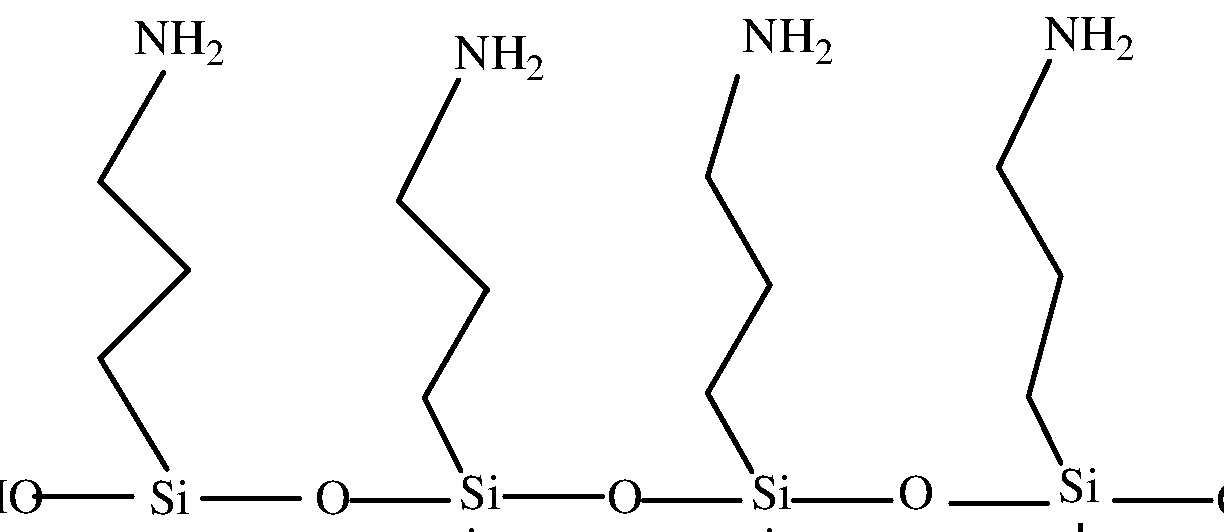
- the preferred siloxane oligomers can be represented by formula:
- Y is independently an amino alkyl group, preferably an amino propyl group, or an alkyl group such as a methyl, ethyl or propyl group, preferably a methyl group and n is an integer from 0 to 18, preferably 2 to13, with the proviso that at least half of the Y groups are amino alkyl groups.
- oligomers of formulae examples of preferred hydroxylated and amino functionalized siloxane oligomers are the oligomers of formulae:
- These intermediate coating compositions are preferably stable aqueous composition.
- Waterborne siloxane oligomer compositions are commercially available under the tradename Dynasilan (R) Hydrosil (R) from Evonik Degussa.
- the siloxane oligomers represent 0.1 to 2 wt%, preferably 0.15 to 1 .5 wt% of the total weight of the composition.
- the intermediate coating composition can be applied by dip coating or spin coating, preferably by dip coating.
- the intermediate coating composition is maintained at a temperature of 20 to 60 °C, preferably 30 to 50 °C, and the dipping process lasts for several hours, generally at least 3 hours, typically from 3 to 12 hours.
- the intermediate layer composition is generally rinsed with water and air dried before application of the LbL coating.
- the thickness of the intermediate layer usually ranges from 1 to 20nm, preferably 1 to 10nm.
- (polycation / polyanion) n Polycation and polyanion are the abbreviations of the specific polyelectrolytes used in the LbL assembly and n is the number of bilayers that have been deposited.
- n a ten bilayer assembly comprising carboxymethylcellulose and chitosan is noted as (CMC/CTS)i 0 .
- the LbL coating may comprise one additional layer of one of the above disclosed constituents. Therefore, for example a LbL assembly of nine bilayers of CMC and CTC including one additional CMC layer is noted (CMC/CTS) 9 5 .
- the LbL coating may comprise 1 to 200 bilayers, preferably 2 to 100, more preferably 2 to 50 bilayers, it preferably comprises 4 to 15 bilayers and more preferably 8 to 12 bilayers.
- the LbL coating will have a physical thickness ranging from 1 nm to 1 ⁇ , preferably from 1 to 200 nm, more preferably from 50 to 100 nm.
- the LbL coating has a refractive index n > 1 .20, preferably > 1 .30 and better ⁇
- the LbL coating is crosslinked through bondings between NH 2 and COOH groups.
- Such a crosslinking is classically performed by treatment with a coupling agent inducing chemical bonds between NH 2 and COOH groups.
- Carbodiimide coupling reagents are well known for the formation of amide linkages.
- Useful carbodiimide-functional compounds have formula:
- EDC is commercially available from TCI America.
- Other useful carbodiimides are ⁇ , ⁇ '- dicyclohexylcarbodiimide and ⁇ , ⁇ '-diisopropylcarbodiimide.
- carbodiimides are often used in combination with hydroxysuccinimide, sulfo- hydroxysucccinimide or N-hydroxybenzotriazole to increase coupling efficiency and decrease side reactions.
- a preferred coupling agent is 1 -ethyl-3-[3-dimethylaminopropyl] carbodiimide (EDC), combined with N-hydroxysuccinimide (NHS) in a buffered solution.
- EDC 1 -ethyl-3-[3-dimethylaminopropyl] carbodiimide
- NHS N-hydroxysuccinimide
- the intermediate layer and the LbL coating are successively deposited on the main surface of the outermost layer of a partial anti-reflective stack of HI and Li layers made of mineral oxides formed by vacuum deposition.
- the LbL layer constitutes the last layer or part of the last layer, generally a LI layer, of the final antireflecting stack.
- the LbL layer constitutes the last layer of the anti-reflective stack, it has generally a physical thickness ranging from 60 to 120 nm, preferably 70 to 100 nm.
- the LbL film When the LbL film is part of the last layer of the antireflecting stack, for example forms a composite layer with a Si0 2 underlayer (10 to 20 nm thick), it has generally a physical thickness of 60 to 80 nm, preferably 65 to 75 nm.
- partial anti-reflective stacks there can be cited the following stacks, from the innermost to the outermost layer
- the LbL coatings made by the process of the invention exhibits excellent antifog properties as well good adhesion properties to the substrate. In particular, they can withstand wet wiping.
- the antifog properties were evaluated by an apparatus slightly modified from European Standard Test (EN168).
- EN168 European Standard Test
- the ambient temperature during the measurement is 23 ⁇ 5 e C.
- the temperature of the water bath is set at 50 ⁇ 0.5 e C.
- the air above the water bath is circulated using a ventilator, so that it becomes saturated with water vapor. During this time, the measurement opening is to be covered.
- the ventilator is switched off before measurement. The samples must be placed in the test position within 2s of the opening being uncovered.
- the measurement spectrum shows the change of T r during a measurement time from 0 to 120s.
- a classical AR stack on an Orma (R) lens exhibits the following results: 5% T r at 60s and 7% at 120s.
- This reference lens is a commercial lens comprising an ORMA® substrate coated on both sides by an abrasion resistant coating as defined below in point "preparation of the substrate” on which have been formed by vacuum deposition, starting from the substrate, an anti-reflective stack comprising 4 layers: a first Zr0 2 layer (27 nm), a second Si0 2 layer (21 nm), a third Zr0 2 layer (80 nm) and a fourth Si0 2 layer (81 nm), and, on top of the anti-reflective stack, an antisoiling coating by evaporation under vacuum of OPTOOL DSX (R) marketed by DAIKIN INDUSTRIES (thickness: from 2 to 5 nm).
- OPTOOL DSX marketed by DAIKIN INDUSTRIES
- the haze value of the final optical article was measured by light transmission utilizing the
- Haze-Guard Plus haze meter from BYK-Gardner (a color difference meter) according to the method of ASTM D1003-00, which is incorporated herein in its entirety by reference. All references to "haze" values in this application are by this standard. The instrument was first calibrated according to the manufacturer's directions. Next, the sample was placed on the transmission light beam of the pre-calibrated meter and the haze value was recorded from three different specimen locations and averaged.
- the mean reflectance factor Rv is such as defined in ISO standard 13666:1998 and measured in accordance with ISO standard 8980-4, i.e. it is the balanced average spectral reflection in the visible spectrum in the wavelengths limits ranging from 380 nm to 780 nm.
- the thickness of the films prepared on frosted glass was evaluated by ellipsometer
- a weight of 725g head with a water dampened micro-fiber cloth immersed in the deionized (Dl) water before use) is applied on a convex side of a lens surface.
- the lens is rubbed for 500 strokes, air dried and then checked if the AR coating is damaged (one stroke: one forward and backward motion).
- Each adhesion level is the average result of three inspection spots on one sample.
- the optical articles were round lenses (piano or - 2.00 with a diameter of 68 mm) comprising an ORMA (R) lens susbtrate (obtained by polymerizing CR-39 (R) diethylene glycol bis ((allyl carbonate) monomer), coated on both faces with a power of -2.00 dioptres and a thickness of 1 .2 mm, coated on both faces with an abrasion-resistant and/or an antiscratch coating (hard coat) disclosed in example 3 of the patent EP 0614957 (refractive index 1 .50, thickness 3.5 nm), based on a hydrolysate of GLYMO and DIVIDES, with colloidal silica and aluminum acetyl acetonate.
- the abrasion-resistant coating was obtained by depositing and curing of a composition comprising by weight, 224 parts of GLYMO, 80.5 parts of HCI 0.1 N, 120 parts of DMDES, 718 parts of a 30 weight% colloidal silica in methanol, 15 parts of aluminum acetyl acetonate and 44 parts of ethylcellulose.
- the composition also comprised 0.1 % of the surfactant FLUORADTM FC-430 ® (3M) by weight as related to the total weight of the composition. This abrasion-resistant coating was deposited directly onto the substrate.
- ZQZQ lens An Orma (R) lens dip-coated with a 3.5 ⁇ hard coat as above is coated by vacuum deposition with four inorganic oxide layers in the indicated order (zirconia 26nm/silica 22nm/zirconia 88nm/ silica 13nm).
- ZQZ lens An Orma (R) lens dip-coated with 3.5 ⁇ hard coat as above is coated by vacuum deposited with three inorganic oxide stacks (zirconia 26nm/silica 22nm/zirconia 87nm).
- Silica coated lens An Orma (R) lens dip-coated with 3.5 ⁇ hard coat as above is coated by vacuum deposition with one silica layer (80nm).
- a layer-by-layer coating is applied onto both sides of a substrate according to the general process described below: I.
- Surface cleaning A lens substrate is first dipped in an ultrasonic caustic solution, and then rinsed in ultrasonic Dl water and air dried.
- the lens is dipped in an adhesive solution, and then rinsed in ultrasonic Dl water and air dried.
- Coating process The treated lens is dipped in a polyanion solution, followed with a rinsing step in two agitated Dl water baths; and then dipped in a polycation solution, followed with a rinsing step in two agitated Dl water baths. This process is repeated for (n-1 ) times and then air dried for 20-30 minutes to get a coating with n bilayers of (polyanion/polycation), written as (polyanion/polycation) n . In some cases, the process is further deposited with polyanion as the outermost layer to get (polyanion/polycation) n+ o. 5 coating.
- Post-treatment The coating is cross-linked in a fresh coupling agent solution, then rinsed in an ultrasonic solution and air dried.
- Adhesive (intermediate layer): Amino functional siloxane oligomer (Dynasilan® Hydrosil ® 2775, 2627 and 1 151 ) used at 0.1 5-1 .5 wt%
- Crosslinking agent 1 -Ethyl-3-[3-dimethylaminopropyl]carbodiimide hydrochloride (EDC) purchased from TCI America, N-hydroxysuccinimide (NHS) purchased from Alfa Aesar.
- EDC Ethyl-3-[3-dimethylaminopropyl]carbodiimide hydrochloride
- NHS N-hydroxysuccinimide
- Buffer solutions 2-(N-Morpholino)ethanesulfonic acid (MES, 0.05M) and Phosphate buffered saline (PBS, 1 x) purchased from Sigma-Aldrich.
- MES 2-(N-Morpholino)ethanesulfonic acid
- PBS Phosphate buffered saline
- a partial anti-reflective AR stack coated lens (ZQZQ) substrate was first dipped in an ultrasonic caustic solution (1wt% of NaOH) for 5min, and then rinsed in ultrasonic Dl water for 5min and air dried.
- the lens was then dipped in a 0.15 or 1 .5wt% of Hydrosil® 2775 aqueous solution at 40-50 e C for 3h or 12h, and then rinsed in ultrasonic Dl water for 5min and air dried.
- the treated lens was dipped in 0.1 wt% of CMC solution for 5min, followed with a rinsing step in two agitated Dl water baths (2 min per bath); and then dipped in 0.1 wt% of CTS solution (added with 0.2wt% of acetic acid) for 5min, followed with a rinsing step in two agitated Dl water baths (2 min per bath).
- the agitation speed is ⁇ 100rpm.
- This process was repeated for another 9 times and the obtained lens was air dried to get a coating (CMC/CTS) 10 .
- the coating was then dipped in a crosslinker aqueous solution 0.2M EDC and 0.05M NHS in the presence of 0.05M MES buffer at pH 5.0 for 1 h, then rinsed in an ultrasonic PBS solution and air dried.
- example 1 was reproduced on a ZQZQ lens except that the step of treating with the adhesive intermediate layer was omitted (only NaOH pre-treatment applied) and that the crosslinked LbL coating was (CTS/CMC) (The CTS layer was first deposited on the lens surface due to negative charges on NaOH treated surface).
- the thickness of the LbL coatings is in the range of 70-90nm.
- a partial anti-reflective AR stack coated lens ZQZ lens was first dipped in an ultrasonic caustic solution (1wt%) for 5min, and then rinsed in ultrasonic Dl water for 5min and air dried. The lens was then dipped in a diluted Hydrosil® 1 151 , 2627 or 2775 aqueous solution at 40- 50 e C for 3h and then rinsed in ultrasonic Dl water for 5min and air dried.
- the following experiment procedure was same as Example C1 -1 except that the LbL coating was (CMC/CTS) 11 5 .
- the crosslinking process is the same as example C1 -1 .
- example C2-1 was reproduced except that the crosslinked LbL coating was (CTS/CMC) 125 prepared on a ZQZ lens(The CTS layer was first deposited on the lens surface) and that the step of treating with the adhesive intermediate layer was omitted (only NaOH pre-treatment applied)
- the thickness of the LbL coatings is in the range of 80-1 OOnm.
- the procedure of making antifog LbL coating was the same as Example C1 -1 except that the AR coated lens was replaced by a glass lens (refractive index 1 .50) and a silica-coated lens. 1 .5wt% of Hydrosil® 2775 was used before applying the LbL coating.
- the LbL coatings were crosslinked (CMC/CTS) 12 5 on substrates treated with Hydrosil® 2775 (C3-1 , C3-2) and a coating (CTS/CMC) 12 5 was applied on each non treated (CE3-1 , CE3-2) substrate as comparison example.
- the thickness of the LbL coatings is in the range of 80-1 OOnm.
- a ZQZ lens was first treated with NaOH and grafted with Hydrosil® 2775.
- the pH of all solutions were titrated to 3.5.
- the lens was dipped in 0.01 M of PAA solution for 2min, followed by rinsing in two agitated Dl water baths (1 min per bath); and then dipped in 0.05wt% of ApSi02 solution for 2min, followed by rinsing in two agitated Dl water baths (1 min per bath).
- the agitation speed is ⁇ 100rpm. This process was repeated for another 8 times and then air dried to get a coating with (PAA/ApSi02) 9 .
- a comparison example (CE4) was prepared on ZQZ by reproducing example C4, except that the intermediate adhesive layer was omitted (there was only NaOH pretreatment) and that the crosslinked coating was (ApSi02/PAA) 95 (The ApSi02 layer was first deposited on the lens surface).
- a partial AR stack coated lens (ZQZQ or ZQZ) substrate was first dipped in an ultrasonic caustic solution (0.5wt% of NaOH) for 5min, and then rinsed in ultrasonic Dl water for 5min and air dried.
- the lens was then dipped in a 1 .5 wt% of Hydrosil ® 2775 aqueous solution at 40-50 e C for 3h, and then rinsed in ultrasonic Dl water for 5min and air dried.
- the treated lens was dipped in 0.1 wt% of circulated filtered CMC solution (5 ⁇ filter membrane) for 3min, followed with a rinsing step in one circulated filtered Dl water bath for 3min; and then dipped in 0.1 wt% of circulated filtered CTS solution containing 0.2wt% of acetic acid for 3min, followed with a rinsing step in one circulated filtered Dl water bath for 3min.
- circulated filtered CMC solution 5 ⁇ filter membrane
- This process was repeated for another 7 times and then air dried to get a coating with (CMC/CTS) 8 on ZQZQ; or the process was repeated for 8 times plus a layer of CMC as the outermost layer, and then air dried to get a coating with (CMC/CTS) 95 on ZQZ.
- the coating was then dipped in a crosslinker aqueous solution (0.2M EDC and 0.05M NHS in the presence of 0.05M MES buffer, pH adjusted to 5.0) for 1 h, then rinsed in an ultrasonic PBS solution and air dried.
- the LbL coatings exhibit poor adhesion properties to the lens substrates.
- cyclic ozasilane 2,2-dimethoxy-1 ,6-diaza-2-silacyclooctane (DDS) and N- methylaza-2,2,4-trimethylsilacyclo-pentane (MATS) are used for forming the adhesive intermediate layer. These compounds are known to react with OH groups by opening of the cycles:
- a partial AR stack coated lens (ZQZQ or ZQZ) substrate was first dipped in an ultrasonic caustic solution (0.5wt% of NaOH) for 5min, and then rinsed in ultrasonic Dl water for 5min and air dried; or the substrate was treated with air or oxygen plasma for 30s.
- the lens was then dipped in a 1 .0 wt% of DDA or MATS anhydrous ethanol solution at room temperature for 10min to 1 , and then rinsed in anhydrous ethanol for 5min and air dried. Since azasilane is sensitive to humidity, this step was conducted in the nitrogen purged dry box (relative humidity ⁇ 15%).
- the treated lens was dipped in 0.1 wt% of circulated filtered CMC solution (5 ⁇ filter membrane) for 3 min, followed with a rinsing step in one circulated filtered Dl water both for 3 min; and then dipped in 0.1 wt% of circulated filtered CTS solution containing 0.2 wt% of acetic acid for 3min, followed with a rinsing step in one circulated filtered Dl water bath for 3min.
- circulated filtered CMC solution 5 ⁇ filter membrane
- This process was repeated for another 7 times and then air dried to get a coating (CMC/CTS) 8 on ZQZQ ; or the process was repeated for 8 times plus a layer of CMC as the outermost layer, and then air dried to get a coating (CMC/CTS) 95 on ZQZ.
- the coating was then dipped in a crosslinker aqueous solution (0.2M EDC and 0.05M NHS in the presence of 0.05 M MES buffer, pH adjusted to 5.0) for 1 h, then rinsed in an ultrasonic PBS solution and air dried.
Abstract
The process comprises: (i) providing a substrate having at least one main surface bearing hydroxyl groups coated with an intermediate layer comprising at least one hydroxylated and aminofunctionalized siloxane oligomer; and (ii) forming on said intermediate layer an anti-fog layer-by-layer (LbL) coating consisting of at least two bilayers obtained by: (a) forming a first layer on the intermediate layer by applying a first composition comprising a polyelectrolyte obtained from carboxyalkyi cellulose or a polyelectrolyte selected from polyacrylic acid (PAA), poly(methacrylic acid) (PMAA), PAA copolymer, PMAA copolymer or mixtures thereof, (b) forming a second layer on the first layer by applying a second composition comprising a polyelectrolyte obtained from polysaccharide including glucosamine units when the first layer comprises the polyelectrolyte obtained from carboxyalkyi cellulose or metal oxide or silicon oxide nanoparticules which are surface functionalized with amino groups when the first layer comprises the polyelectrolyte obtained from polyacrylic acid, poly(methacrylic acid), PAA copolymer or PMAA copolymer. (c) optionally repeating at least once steps (a) and (b); and (d) crosslinking the layers of the LbL coating by treatment with a composition of a coupling agent.
Description
PROCESS FOR PREPARING ARTICLES HAVING ANTI-FOG LAYER BY LAYER COATING AND COATED ARTICLES HAVING ENHANCED ANTI-FOG
AND DURABILITY PROPERTIES BACKGROUND OF THE INVENTION
1. Field of the invention
This invention relates to a process for preparing an article bearing an anti-fog layer-by- layer coating and to the articles bearing an anti-fog layer-by layer coating obtained by said process, more particularly optical and ophthalmic articles, especially ophthalmic lenses for eyeglasses.
The invention is based on the use of a specific intermediate layer enhancing the adhesion of said anti-fog layer-by-layer coating, in particular on metal oxide and silicon oxide layers usually formed by vacuum deposition.
2. Description of related art
It is known in the art that a layer-by-layer (LbL) coating can be assembled on a substrate from species having opposite charges, typically positively and negatively charged polyelectrolytes can be alternately deposited on a substrate.
In a general manner, at least two different polyelectrolyte solutions having opposite charges, or a polyelectrolyte solution and a nanoparticle solution having opposite charges, may be used to form the LbL coating.
As known in the art, a polyelectrolyte may be a polymer having a substantial portion of its repeating units bearing an electrolyte group. These groups are ionic or ionizable groups, especially in aqueous solutions.
Other known LbL coatings include a plurality of bilayers alternately comprising oppositely charged nanoparticles.
By selecting the materials of the layers and the deposition process conditions, such films can be anti-reflective, hydrophilic or superhydrophilic, hydrophobic or superhydrophobic.
LbL coatings having hydrophilic properties may also have anti-fog properties.
US 2007/0104922 describes superhydrophilic LbL coatings that can be anti-reflective and anti-fog, such as poly( allylamine hydrochloride)/Si02 LbL coatings.
A disadvantage of the anti-fog LbL coatings is that such coatings exhibit generally poor mechanical properties, especially poor adhesion, i.a. to mineral substrates and to metal oxides and silicone oxides layers. Mechanical properties of LbL coatings have been increased by calcination treatment, generally at high temperature (typically 550 °C).
A disadvantage associated to this technique is that it cannot be applied on any organic substrates and is only adapted to substrates that can withstand high temperature like glass substrates.
In the article "Hydrothermal Treatment of Nanoparticle Thin Films for Enhanced
Mechanical Durability" Z.Gemici et al, Langmuir 2008, 24, 2168-2177, a hydrothermal treatment implemented at around 125°C, of different LbL coatings is described in order to improve mechanical durability of these coatings and avoid delamination, especially on a polycarbonate (PC) substrate.
A typical example of a LbL coating is either a polymer-nanoparticle coating made alternatively from a positively charged poly(diallyldimethyl ammonium chloride) and negatively charged silica nanoparticles, or an all-nanoparticle coating assembled alternatively from positively charged 3-aminopropyl silane modified silica (or titania) nanoparticles and negatively charged silica nanoparticles. After a hydrothermal treatment, such LbL coating has improved abrasion resistance.
US 2008/0038458 describes a hydrothermal calcination of Ti02/Si02 LbL coatings, typically at a pressure in the range of 10 psi to 30 psi at temperature less than 500 °C.
One disadvantage of the technique, along with the necessity of using an autoclave, is that the hydrothermal treatment affects the anti-fog properties of the coating, as explained in US 2008/0038458 paragraph [0046]: the coating can lose its anti-fog properties.
Consequently, it is desirable to provide a new and simple process of preparation of anti- fog LbL coatings having good or improved anti-fog properties, along with good mechanical properties such as improved adhesion to the substrate and/or improved abrasion resistance.
The adhesive function of water-borne silanes has been reported in several publications and in particular in the article "Factors contributing to the stability of alkoxysilanes in aqueous solution", B. Ahles, J. R. Steimmetz, J. Zazyczny and P. Metha, J. Adh. Sci. Tech. 6, (1 ), 193, 1992. Mention of Hydrosil™ materials was made in several patents, namely U.S. Pat. Nos. 7,217,756; 6,180,244; 6,406,782; 6,372,827; 5,363,994; and 6,284,360.
There is no disclosure of the use of aminosiloxane waterbone primers in combination with an anti-fog LbL coating as the polymeric coating and no disclosure that such kind of materials can improve the mechanical properties of a LbL system without impairing the anti-fog properties of the system.
SUMMARY OF THE INVENTION
An object of the invention is to improve the mechanical durability of anti-fog LbL coatings, especially adhesion properties, for a wide range of substrates and to metal oxides and silicon oxides layers while maintaining good anti-fog properties and keeping the deposition process of such anti-fog LbL coating as simple as possible.
A further object of the invention is to provide an anti-fog LbL coating having the improved mechanical properties mentioned above without concurrently decreasing its optical transparency in the visible range.
The present invention discloses that the adhesion properties of a LbL coating are improved by using a specific process for preparing an article having anti-fog properties, comprising:
(i) providing a substrate having at least one main surface bearing hydroxyl groups coated with an intermediate layer obtained by applying on said main surface of the substrate an intermediate layer composition comprising at least one hydroxylated and amino-functionalized siloxane oligomer; and
(ii) forming on said intermediate coating an anti-fog LbL coating consisting of at least two bilayers obtained by:
(a) forming a first layer on the intermediate coating by applying a first composition comprising a polyelectrolyte obtained from carboxyalkyi cellulose or a polyelectrolyte obtained from polyacrylic acid (PAA), poly(methacrylic acid) (PMAA), PAA copolymer, PMAA copolymer, or mixtures thereof, preferably polyacrylic acid,
(b) forming a second layer on the first layer by applying a second composition comprising a polyelectrolyte obtained from a polysaccharide including glucosamine units when the first layer comprises a polyelectrolyte obtained from carboxyalkyi cellulose or metal oxide or silicon oxide nanoparticles which are surface functionalized with amine groups when the first layer comprises the polyelectrolyte obtained from polyacrylic acid, poly(methacrylic acid), PAA copolymer, PMAA copolymer or mixtures thereof,
(c) optionally repeating at least once steps (a) and (b); and
(d) crosslinking the layers of the LbL coating by treatment with a composition of a coupling agent inducing chemical linkages between NH2 and COOH groups, said crosslinking being performed either after step (b) or step (c).
The invention also relates to an optical article comprising a substrate having an antifog LbL coating obtainable by implementing the above described process.
In one embodiment of the invention, the intermediate layer composition is an aqueous composition and preferably the hydroxylated and amino-functionalized siloxane oligomer is linear and comprises 1 to 50, preferably 2 to 20, more preferably 4 to 15 siloxane units.
The intermediate layer of the invention improves the adhesion between a substrate and the anti-fog LbL coating, but also improves or maintains the anti-fog performance of LbL coating.
In a preferred embodiment the LbL coating constitutes the outermost layer or part of the outermost layer of an anti-reflecting multilayered coating, typically a low refractive index layer.
Other objects, features and advantages of the present invention will become apparent from the following detailed description.
DETAILED DESCRIPTION OF THE INVENTION AND PREFERRED EMBODIMENTS
The terms "comprise" (and any grammatical variation thereof, such as "comprises" and "comprising"), "have" (and any grammatical variation thereof, such as "has" and "having"), "contain" (and any grammatical variation thereof, such as "contains" and "containing"), and "include" (and any grammatical variation thereof, such as "includes" and "including") are open- ended linking verbs. They are used to specify the presence of stated features, integers, steps or
components or groups thereof, but do not preclude the presence or addition of one or more other features, integers, steps or components or groups thereof. As a result, a method, or a step in a method, that "comprises," "has," "contains," or "includes" one or more steps or elements possesses those one or more steps or elements, but is not limited to possessing only those one or more steps or elements.
Unless otherwise indicated, all numbers or expressions referring to quantities of ingredients, ranges, reaction conditions, etc. used herein are to be understood as modified in all instances by the term "about."
When an optical article comprises one or more surface coatings, the phrase "to deposit a coating or layer onto the optical article" means that a coating or layer is deposited onto the outermost coating of the optical article, i.e. the coating which is the closest to the air.
A coating that is "on" a side of a lens is defined as a coating that (a) is positioned over that side, (b) need not be in contact with that side, i.e., one or more intervening coatings may be disposed between that side and the coating in question, and (c) need not cover that side completely.
As used herein, the phrase "last layer" means a monolayer or a multilayer which is in contact with the environmental air.
As used herein, the phrase "outermost coating" or "outermost layer" means a coating or a layer which is the farthest from the substrate and conversely the phrase "innermost coating" or "innermost layer" means a coating or a layer which is the closest to the substrate.
As used herein, the term "substrate" means a naked substrate or a naked substrate already coated with one or several functional coatings.
The optical article prepared according to the present invention is a transparent optical article, preferably a lens or lens blank, and more preferably an ophthalmic lens or lens blank. The optical article may be coated on its convex main side (front side (Cx)), concave (Cc) main side (back side), or both sides using the process of the invention.
Herein, the term "lens" means an organic or inorganic glass lens, comprising a lens substrate which may be coated with one or more coatings of various natures.
The lens naked substrate may be made of mineral glass or organic glass, preferably organic glass. The organic glasses can be either thermoplastic materials such as polycarbonates and thermoplastic polyurethanes or thermosetting (cross-linked) materials such as diethylene glycol bis(allylcarbonate) polymers and copolymers (in particular CR-39® from PPG Industries), thermosetting polyurethanes, polythiourethanes, polyepoxides, polyepisulfides, poly(meth)acrylates and copolymers based substrates, such as substrates comprising (meth)acrylic polymers and copolymers derived from bisphenol-A, polythio(meth)acrylates, as well as copolymers thereof and blends thereof. Preferred materials for the lens substrate are polycarbonates (PC) and diethylene glycol bis(allylcarbonate) polymers, in particular substrates made of polycarbonate.
The surface of the article onto which the intermediate coating will be applied may optionally be subjected to a pre-treatment step intended to improve adhesion, for example a
high-frequency discharge plasma treatment, a glow discharge plasma treatment, a corona treatment, an electron beam treatment, an ion beam treatment, an acid or base treatment.
The intermediate layer of the invention may be deposited onto a naked substrate or onto the outermost coating layer of the substrate if the substrate is coated with at least one surface coating. Said at least one surface coating may be, without limitation, an impact-resistant coating (impact resistant primer), an abrasion and/or scratch resistant coating, a polarized coating, a photochromic coating, a dyed coating, an anti-reflecting or a partial anti-reflecting coating. Preferably, the intermediate coating of the invention is applied on the outermost layer of an anti- reflecting or partial anti-reflecting coating.
The impact-resistant coating which may be used in the present invention can be any coating typically used for improving impact resistance of a finished optical article. This coating generally enhances adhesion of the abrasion and/or scratch-resistant coating on the substrate of the finished optical article. By definition, an impact-resistant primer coating is a coating which improves the impact resistance of the finished optical article as compared with the same optical article but without the impact-resistant primer coating.
Typical impact-resistance primer coatings are (meth)acrylic based coatings and polyurethane based coatings, in particular coatings made from a latex composition such as a poly(meth)acrylic latex, a polyurethane latex or a polyester latex.
Polyurethane-polyester latexes are commercially available from ZENECA RESINS under the trade name Neorez® (e.g., Neorez® R-962, Neorez® R-972, Neorez® R-986, Neorez® R- 9603) or BAXENDEN CHEMICALS, a subsidiary of WITCO Corporation, under the trade name Witcobond® (e.g., Witcobond® 232, Witcobond® 234, Witcobond® 240, Witcobond® 242).
The abrasion- and/or scratch-resistant coating which may be used in the present invention can be any coating typically used for improving abrasion- and/or scratch-resistance of a finished optical article as compared to a same optical article but without the abrasion- and/or scratch-resistant coating.
Preferred abrasion- and/or scratch-resistant coatings are (meth)acrylate based coatings and silicon-containing coatings. The latter are more preferred and are disclosed, for example, in French patent application FR 2702486, which is incorporated herein by reference.
The anti-reflective coating which may be used in the invention can be any well known anti-reflective coating, typically a stack of high refractive (HI) and low refractive (LI) index layers.
The refractive indices are measured by using an infrared ellipsometer at 634 nm. This method is disclosed in A. BRUNET-BRUNEAU, S. FISSON, G. VUYE, J. RIVORY, J. Appl. Phys. 2000, 87, 7303-7309, and A. BRUNET-BRUNEAU, S. FISSON, B. GALLAS, G. VUYE, J. RIVORY, Thin Solid Films 2000, 377, 57-61 .
As used herein, a low refractive index layer is intended to mean a layer with a refractive index n of 1 .55 or less, preferably lower than 1 .50 and even better lower than 1 .45, and a high refractive index layer is intended to mean a layer with a refractive index n higher than 1 .55, preferably higher than 1 .6, more preferably higher than 1 .8 and even better higher than 2.
HI layers are classical high refractive index layers and may comprise, without limitation,
one or more mineral oxides such as Ti02, PrTi03, LaTi03, Zr02, Ta205, Y203, Ce203, La203, Dy205, Nd205, Hf02, Sc203, Pr203 or Al203, or Si3N4, as well as mixtures thereof, preferably Zr02, Ti02 or PrTi03. HI layers may optionally contain low refractive index materials such as Si02. Obviously, mixtures of those compounds are such that the refractive index of the resulting layer is as defined above (higher than 1 .55).
LI layers are also well known and may comprise, without limitation, Si02, SiOx with 1≤x<2, MgF2, ZrF4, Al203, AIF3, chiolite (Na5AI3F14]), cryolite (Na3AIF6), or mixtures thereof, preferably Si02 or Si02 doped with Al203 which contributes to raising the critical temperature of the stack. Obviously, mixtures of those compounds are such that the refractive index of the resulting layer is as defined above (lower than or equal to 1 .55). When Si02/Al203 mixtures are used, the LI layer preferably contains from 1 to 10%, more preferably from 1 to 8% by weight of Al203 relative to the total weight of Si02 + Al203 in said layer. A too high amount of alumina is detrimental to the adhesion of the AR coating.
For example, Si02 doped with 4% or less Al203 by weight, or Si02 doped with 8% Al203 by weight may be employed. Commercially available Si02/Al203 mixtures can also be employed, such as LIMA® supplied by Umicore Materials AG (refractive index n = -1 .48 at 550 nm), or substance L5® supplied by Merck KGaA (refractive index n = 1 .48 at 500 nm). The most preferred material for LI layers is Si02 doped with 8% Al203 by weight.
Generally, HI layers and LI layers, have a physical thickness, ranging from 10 to 120 nm (HI) and 10 to 100 nm (LI), respectively.
The antireflecting stack of the present invention may include any layer or stack of layers which improves the anti-reflective properties of the finished optical article over at least one portion of the visible spectrum, thereby increasing the transmission of light and reducing surface reflectance.
Preferably, the multi-layer antireflecting stack comprises, in addition to the innermost and outermost layers, at least one LI layer and at least two HI layers. Preferably, the total number of layers in the anti-reflection coating is≤ 9, preferably≤ 7.
LI and HI layers are not necessarily alternated in the AR stack, although the anti- reflection coating may comprise an alternated stack of low refractive index and high refractive index layers according to a particular embodiment of the invention. Two or more HI layers may be deposited on one another; two or more LI layers may be deposited on one another.
In general, the total thickness of the antireflecting stack is less than 1 .5 μηι, preferably 1 μηι or less, and even better 0.5 μηι or less, and generally ranging from 0.2 to 0.5μηι.
The HI and LI layers are generally applied by vacuum deposition according to one of the following techniques:
1 ) - by evaporation, optionally ion beam-assisted;
2) - by spraying using an ion beam,
3) - by cathode sputtering; or
4) - by plasma-assisted vapor-phase chemical deposition.
These different methods are described in "Thin Film Processes" and "Thin Film
Processes II", Vossen & Kern, Ed., Academic Press, 1978 and 1981 , respectively. Said evaporation under vacuum is a particularly recommended method.
These layers can also be applied by applying liquid solutions, preferably by a spin coating process.
The article of the invention may be made antistatic by incorporating at least one electrically conductive layer into the antireflecting stack. The electrically conductive layer may be located in various locations of the antireflecting stack, provided its antireflection properties are not impaired. It is preferably located under a low refractive index layer of the antireflecting stack.
The electrically conductive layer must be thin enough not to impair the transparency of the antireflection coating. Typically, its thickness does vary from 0.1 to 50 nm, more preferably from 0.1 to 30 nm, depending on its nature. When it is less than 0.1 nm thick, it does not typically enable to obtain a sufficient electrical conductivity, on the contrary when it is more than 50 nm thick, it mat be difficult to obtain the required transparency and low absorption characteristics.
The electrically conductive layer is preferably made of an electrically conductive and highly transparent material. In that case, its thickness does preferably vary from 0.1 to 30 nm, more preferably from 1 to 20 nm and even more preferably from 1 to 10 nm. The electrically conductive layer preferably comprises a metal oxide selected from indium, tin, and zinc oxide, as well as mixtures thereof. Indium-tin oxide (ln203:Sn, i.e. indium oxide doped with tin) and tin oxide (Sn02) are preferred. According to an optimal embodiment, the electrically conductive and optically transparent layer is an indium-tin oxide layer, referred to an ITO layer.
Typically, the electrically conductive layer does contribute to obtain the antireflection properties and form a high refractive index layer in the antireflection coating. That is the case when layers are made of an electrically conductive and highly transparent material such as the ITO layers.
The electrically conductive layer may also be a layer made of a very thin noble metal that is typically less than 1 nm thick, more preferably less than 0.5 nm thick.
The electrically conductive layer, that is typically a high refractive index layer of the antireflection stack, may be deposited according to any suitable method, for example by vacuum deposition, by evaporation, preferably by ion beam assisted deposition (IAD), or by a cathode sputtering or ion beam method.
In a preferred embodiment of the invention, the anti-reflecting coating comprises a partial anti-reflective coating made of a stack of HI and LI layers as disclosed above which is completed by the intermediate layer and the LbL coating of the invention. Then, the intermediate coating and the LbL coating constitutes the outermost or part of the outermost layer of the anti-reflective coating. Typically, this outermost layer of the anti-reflective coating is a low refractive index layer.
As previously mentioned, the intermediate layer composition comprises at least one hydroxylated and aminofunctionalized siloxane oligomer.
As known by the man skilled in the art, an oligomer is a polymer comprising a limited number of repeating molecular units, typically 2 to 50.
The siloxane oligomer used in the intermediate layer composition typically comprises 1 to 50 siloxane
I
(-Si-O-)
I
units, preferably from 2 to 20, more preferably 4 to 15 siloxane units.
In the above siloxane unit, the Si atom is linked with at least two monovalent groups, such as an alkyl group, a hydroxyl group, a functionalizing amino group.
Although the siloxane oligomer may be a cyclic or branched oligomer it is preferably a linear oligomer.
Preferably, the functionalizing amino group is a -Z-NH2 group wherein Z represents a divalent group of formula
-[A-(NH)]X -A' - wherein A represents -(CH2)y- and A' represents -(CH2)Z- and x is an integer from 0 to 5, preferably from 0 to 3 ;
y and z are each independently an integer from 1 to 5.
Preferably, the functionalizing amino group is an amino-alkyl group such as an amino methyl, aminoethyl, aminopropyl and aminobutyl group, more preferably an aminopropyl group. Another preferred functionalizing group is -CH2CH2NHCH2CH2NHCH2CH2NH2.
The preferred siloxane oligomers can be represented by formula:

Examples of preferred hydroxylated and amino functionalized siloxane oligomers are the oligomers of formulae:

These intermediate coating compositions are preferably stable aqueous composition.
Waterborne siloxane oligomer compositions are commercially available under the tradename Dynasilan(R) Hydrosil(R) from Evonik Degussa.
Typically the siloxane oligomers represent 0.1 to 2 wt%, preferably 0.15 to 1 .5 wt% of the total weight of the composition.
The intermediate coating composition can be applied by dip coating or spin coating, preferably by dip coating.
During dip coating process, the intermediate coating composition is maintained at a temperature of 20 to 60 °C, preferably 30 to 50 °C, and the dipping process lasts for several hours, generally at least 3 hours, typically from 3 to 12 hours.
The intermediate layer composition is generally rinsed with water and air dried before application of the LbL coating.
After drying, the thickness of the intermediate layer usually ranges from 1 to 20nm, preferably 1 to 10nm.
For convenience in expressing the assembled system, the following notation is commonly used: (polycation / polyanion)n. Polycation and polyanion are the abbreviations of the specific polyelectrolytes used in the LbL assembly and n is the number of bilayers that have
been deposited. For example, a ten bilayer assembly comprising carboxymethylcellulose and chitosan is noted as (CMC/CTS)i0. Sometimes the LbL coating may comprise one additional layer of one of the above disclosed constituents. Therefore, for example a LbL assembly of nine bilayers of CMC and CTC including one additional CMC layer is noted (CMC/CTS)9 5.
Although the LbL coating may comprise 1 to 200 bilayers, preferably 2 to 100, more preferably 2 to 50 bilayers, it preferably comprises 4 to 15 bilayers and more preferably 8 to 12 bilayers.
Typically the LbL coating will have a physical thickness ranging from 1 nm to 1 μηι, preferably from 1 to 200 nm, more preferably from 50 to 100 nm.
In general, the LbL coating has a refractive index n > 1 .20, preferably > 1 .30 and better≥
1 .40 and ≤ 1 .55, preferably≤ 1 .52.
As indicated the LbL coating is crosslinked through bondings between NH2 and COOH groups.
Such a crosslinking is classically performed by treatment with a coupling agent inducing chemical bonds between NH2 and COOH groups. Carbodiimide coupling reagents are well known for the formation of amide linkages. Useful carbodiimide-functional compounds have formula:
N(CH3)2-(CH2)n-N=C=N-CH2CH3, wherein n is an integer from 2 to 6. Particularly, preferred compound is the compound with n=3, 1 -ethyl-3 (-3-dimethylaminopropyl) carbodiimide (EDC). EDC is commercially available from TCI America. Other useful carbodiimides are Ν,Ν'- dicyclohexylcarbodiimide and Ν,Ν'-diisopropylcarbodiimide.
These carbodiimides are often used in combination with hydroxysuccinimide, sulfo- hydroxysucccinimide or N-hydroxybenzotriazole to increase coupling efficiency and decrease side reactions.
Synthesis of carbodiimides are disclosed by Sheehan, John; Cruishank, Philip, Boshart,
Gregory (1961 ) in "A Convenient Synthesis of Water Soluble Carbodiimides" J. Org. Chem. 26 (7), 2525, and by Nakajima, N; Ikada, Y (1995) in "Mechanism of Amide Formation by Carbodiimide for Bioconjugation in Aqueous Media" Bioconjugate Chem. 6 (1 ), 123.
A preferred coupling agent is 1 -ethyl-3-[3-dimethylaminopropyl] carbodiimide (EDC), combined with N-hydroxysuccinimide (NHS) in a buffered solution.
In preferred embodiments the intermediate layer and the LbL coating are successively deposited on the main surface of the outermost layer of a partial anti-reflective stack of HI and Li layers made of mineral oxides formed by vacuum deposition. In that case the LbL layer constitutes the last layer or part of the last layer, generally a LI layer, of the final antireflecting stack. When the LbL layer constitutes the last layer of the anti-reflective stack, it has generally a physical thickness ranging from 60 to 120 nm, preferably 70 to 100 nm. When the LbL film is part of the last layer of the antireflecting stack, for example forms a composite layer with a Si02 underlayer (10 to 20 nm thick), it has generally a physical thickness of 60 to 80 nm, preferably 65 to 75 nm.
As examples of partial anti-reflective stacks there can be cited the following stacks, from
the innermost to the outermost layer
Zr02/Si02/Zr02/Si02 (ZQZQ) and
Zr02/Si02/Zr02 (ZQZ)
In this last stack, the Si02 layer has been omitted and will be replaced by the LbL coating.
The LbL coatings made by the process of the invention exhibits excellent antifog properties as well good adhesion properties to the substrate. In particular, they can withstand wet wiping.
The present invention will now be described with reference to the following examples: EXAMPLES
1 - TESTING METHODS
The following test procedures were used to evaluate the optical articles according to the present invention. a) Fog test according to EN 168 Standard
The antifog properties were evaluated by an apparatus slightly modified from European Standard Test (EN168). The ambient temperature during the measurement is 23±5eC. The temperature of the water bath is set at 50±0.5eC. The air above the water bath is circulated using a ventilator, so that it becomes saturated with water vapor. During this time, the measurement opening is to be covered. The ventilator is switched off before measurement. The samples must be placed in the test position within 2s of the opening being uncovered.
To measure the transmittance change, the sample is placed on the seating ring, with one side exposed to the water vapor and the upper side exposed to the air. The relative transmittance (Tr) is recorded as Tr % = (Tf Ti)*100 =(lf/li)*100, where the initial transmittance (T,) is determined by laser intensity (I,) passing through the sample in the non-fogging conditions, and the transmittance (Tf) is determined by laser intensity (lf) passing through the sample during the fogging condition. The measurement spectrum shows the change of Tr during a measurement time from 0 to 120s.
Two Tr data at 60s and 120s of each sample are listed in the table for sample comparison.
As a comparison and reference, a classical AR stack on an Orma(R) lens exhibits the following results: 5% Tr at 60s and 7% at 120s.
This reference lens is a commercial lens comprising an ORMA® substrate coated on both sides by an abrasion resistant coating as defined below in point "preparation of the
substrate" on which have been formed by vacuum deposition, starting from the substrate, an anti-reflective stack comprising 4 layers: a first Zr02 layer (27 nm), a second Si02 layer (21 nm), a third Zr02 layer (80 nm) and a fourth Si02 layer (81 nm), and, on top of the anti-reflective stack, an antisoiling coating by evaporation under vacuum of OPTOOL DSX(R) marketed by DAIKIN INDUSTRIES (thickness: from 2 to 5 nm). b) Haze value, Rv and thickness
The haze value of the final optical article was measured by light transmission utilizing the
Haze-Guard Plus haze meter from BYK-Gardner (a color difference meter) according to the method of ASTM D1003-00, which is incorporated herein in its entirety by reference. All references to "haze" values in this application are by this standard. The instrument was first calibrated according to the manufacturer's directions. Next, the sample was placed on the transmission light beam of the pre-calibrated meter and the haze value was recorded from three different specimen locations and averaged.
The mean reflectance factor Rv is such as defined in ISO standard 13666:1998 and measured in accordance with ISO standard 8980-4, i.e. it is the balanced average spectral reflection in the visible spectrum in the wavelengths limits ranging from 380 nm to 780 nm.
The thickness of the films prepared on frosted glass was evaluated by ellipsometer
(thickness < 1 μηι) equipped with M-44TM, EC-270 and LPS-400 with 75W Xenon Light Source from J. A. Woollam Co. Inc., or the thickness of the layers and films coated on lenses was measured by with a Metricon Model 2010 Prism Coupler apparatus (thickness > 1 μηι) from
Metricon Corporation. c) Adhesion (Wet rubbing test)
A weight of 725g head with a water dampened micro-fiber cloth (immersed in the deionized (Dl) water before use) is applied on a convex side of a lens surface. The lens is rubbed for 500 strokes, air dried and then checked if the AR coating is damaged (one stroke: one forward and backward motion). There are four levels of adhesion after the rubbing test, determined by scratch numbers observed in a square of 100 μηι X 100 μηι micro-photograph of the rubbed surfaces (magnification 5X or 10X).
Each adhesion level is the average result of three inspection spots on one sample.

2 - PREPARATION OF THE SUBSTRATE
In all examples the optical articles were round lenses (piano or - 2.00 with a diameter of
68 mm) comprising an ORMA(R) lens susbtrate (obtained by polymerizing CR-39(R) diethylene glycol bis ((allyl carbonate) monomer), coated on both faces with a power of -2.00 dioptres and a thickness of 1 .2 mm, coated on both faces with an abrasion-resistant and/or an antiscratch coating (hard coat) disclosed in example 3 of the patent EP 0614957 (refractive index 1 .50, thickness 3.5 nm), based on a hydrolysate of GLYMO and DIVIDES, with colloidal silica and aluminum acetyl acetonate.
More precisely, the abrasion-resistant coating (hardcoat) was obtained by depositing and curing of a composition comprising by weight, 224 parts of GLYMO, 80.5 parts of HCI 0.1 N, 120 parts of DMDES, 718 parts of a 30 weight% colloidal silica in methanol, 15 parts of aluminum acetyl acetonate and 44 parts of ethylcellulose. The composition also comprised 0.1 % of the surfactant FLUORAD™ FC-430® (3M) by weight as related to the total weight of the composition. This abrasion-resistant coating was deposited directly onto the substrate.
ZQZQ lens: An Orma(R) lens dip-coated with a 3.5 μηι hard coat as above is coated by vacuum deposition with four inorganic oxide layers in the indicated order (zirconia 26nm/silica 22nm/zirconia 88nm/ silica 13nm).
ZQZ lens: An Orma(R) lens dip-coated with 3.5 μηι hard coat as above is coated by vacuum deposited with three inorganic oxide stacks (zirconia 26nm/silica 22nm/zirconia 87nm).
Silica coated lens: An Orma(R) lens dip-coated with 3.5 μηι hard coat as above is coated by vacuum deposition with one silica layer (80nm).
3 - EXPERIMENTAL DETAILS
A layer-by-layer coating is applied onto both sides of a substrate according to the general process described below: I. Surface cleaning: A lens substrate is first dipped in an ultrasonic caustic solution, and then rinsed in ultrasonic Dl water and air dried.
II. Surface pre-treatment: In some cases, the lens is dipped in an adhesive solution, and then rinsed in ultrasonic Dl water and air dried.
III. Coating process: The treated lens is dipped in a polyanion solution, followed with a rinsing step in two agitated Dl water baths; and then dipped in a polycation solution, followed with a rinsing step in two agitated Dl water baths. This process is repeated for (n-1 ) times and then air dried for 20-30 minutes to get a coating with n bilayers of (polyanion/polycation), written as (polyanion/polycation)n. In some cases, the process is further deposited with polyanion as the outermost layer to get (polyanion/polycation)n+o.5 coating.
IV. Post-treatment: The coating is cross-linked in a fresh coupling agent solution, then rinsed in an ultrasonic solution and air dried.
Name and conditions of chemicals used here:
Polycation: chitosan (CTS, low molecular weight, used at 0.1wt% in water added with
0.2wt% of acetic acid for solubility improvement, pH=4.0) and ApSi02 (Aminopropyl funtionalized silica nanoparticles) (15nm, 3.0w/v% in ethanol, used at 0.005wt% in water, pH=3.5) purchased from Sigma-Aldrich
Polyanion: sodium carboxymethyl cellulose purchased from Sigma-Aldrich (CMC, Mw=250,000, used at 0.1 wt% in water, pH=4.0), polyacrylic acid purchased from
Polysciences, Inc (PAA, used as 0.01 M in water, pH=3.5)
Adhesive (intermediate layer): Amino functional siloxane oligomer (Dynasilan® Hydrosil ® 2775, 2627 and 1 151 ) used at 0.1 5-1 .5 wt%

Crosslinking agent: 1 -Ethyl-3-[3-dimethylaminopropyl]carbodiimide hydrochloride (EDC) purchased from TCI America, N-hydroxysuccinimide (NHS) purchased from Alfa Aesar.
Buffer solutions: 2-(N-Morpholino)ethanesulfonic acid (MES, 0.05M) and Phosphate buffered saline (PBS, 1 x) purchased from Sigma-Aldrich.
Examples C1-1 , C1 -2 and comparative example CE1 :
A partial anti-reflective AR stack coated lens (ZQZQ) substrate was first dipped in an ultrasonic caustic solution (1wt% of NaOH) for 5min, and then rinsed in ultrasonic Dl water for 5min and air dried. The lens was then dipped in a 0.15 or 1 .5wt% of Hydrosil® 2775 aqueous solution at 40-50eC for 3h or 12h, and then rinsed in ultrasonic Dl water for 5min and air dried. In the LbL coating process, the treated lens was dipped in 0.1 wt% of CMC solution for 5min, followed with a rinsing step in two agitated Dl water baths (2 min per bath); and then dipped in 0.1 wt% of CTS solution (added with 0.2wt% of acetic acid) for 5min, followed with a rinsing step in two agitated Dl water baths (2 min per bath). The agitation speed is ~100rpm. This process was repeated for another 9 times and the obtained lens was air dried to get a coating (CMC/CTS)10. The coating was then dipped in a crosslinker aqueous solution 0.2M EDC and 0.05M NHS in the presence of 0.05M MES buffer at pH 5.0 for 1 h, then rinsed in an ultrasonic PBS solution and air dried.
In a comparison example (CE1 ), example 1 was reproduced on a ZQZQ lens except that the step of treating with the adhesive intermediate layer was omitted (only NaOH pre-treatment applied) and that the crosslinked LbL coating was (CTS/CMC) (The CTS layer was first deposited on the lens surface due to negative charges on NaOH treated surface). The thickness of the LbL coatings is in the range of 70-90nm.
Rv, % of Haze, EN 168 Tr % Adhesion
Sample Adhesive coating
Cc side % 1 min 2 min (wet rubbing test)
CE1 / 0.33 0.87 83 85 Bad
C1 -1 2775, 1 .5wt%, 3h 1 .04 0.88 87 84 Excellent
C1 -2 2775, 0.15wt%, 12h 0.98 0.63 89 91 Excellent
Examples C2-1 , C2-2; C2-3 and comparative example CE2:
A partial anti-reflective AR stack coated lens ZQZ lens was first dipped in an ultrasonic caustic solution (1wt%) for 5min, and then rinsed in ultrasonic Dl water for 5min and air dried. The lens was then dipped in a diluted Hydrosil® 1 151 , 2627 or 2775 aqueous solution at 40- 50eC for 3h and then rinsed in ultrasonic Dl water for 5min and air dried. The following experiment procedure was same as Example C1 -1 except that the LbL coating was (CMC/CTS)11 5. The crosslinking process is the same as example C1 -1 .
In comparison example (CE2), example C2-1 was reproduced except that the crosslinked LbL coating was (CTS/CMC)125 prepared on a ZQZ lens(The CTS layer was first deposited on the lens surface) and that the step of treating with the adhesive intermediate layer was omitted (only NaOH pre-treatment applied) The thickness of the LbL coatings is in the range of 80-1 OOnm.

The procedure of making antifog LbL coating was the same as Example C1 -1 except that the AR coated lens was replaced by a glass lens (refractive index 1 .50) and a silica-coated lens. 1 .5wt% of Hydrosil® 2775 was used before applying the LbL coating. The LbL coatings were crosslinked (CMC/CTS)12 5 on substrates treated with Hydrosil® 2775 (C3-1 , C3-2) and a coating (CTS/CMC)12 5 was applied on each non treated (CE3-1 , CE3-2) substrate as comparison example. The thickness of the LbL coatings is in the range of 80-1 OOnm.
Adhesive Haze, EN 168 Tr% Adhesion
Substrate Sample
coating % 1 min 2 min (wet rubbing test)
Silica coated CE3-1 / 0.77 94 95 Bad
lens C3-1 2775, 3h 0.59 95 95 Excellent
CE3-2 / 0.64 99 98 Bad
Glass lens C3-2 2775, 3h 0.91 94 92 Excellent
Example C4 and comparative example CE4:
As in Example C2-3, a ZQZ lens was first treated with NaOH and grafted with Hydrosil® 2775. In the LbL coating process, the pH of all solutions were titrated to 3.5. The lens was dipped in 0.01 M of PAA solution for 2min, followed by rinsing in two agitated Dl water baths (1 min per bath); and then dipped in 0.05wt% of ApSi02 solution for 2min, followed by rinsing in two agitated Dl water baths (1 min per bath). The agitation speed is ~100rpm. This process was repeated for another 8 times and then air dried to get a coating with (PAA/ApSi02)9. The coating was then dipped in a crosslinker aqueous solution (0.2M EDC and 0.05M NHS in the presence of 0.05M MES buffer at pH 5.0) for 1 h, then rinsed in an ultrasonic PBS solution and air dried. A comparison example (CE4) was prepared on ZQZ by reproducing example C4, except that the intermediate adhesive layer was omitted (there was only NaOH pretreatment) and that the crosslinked coating was (ApSi02/PAA)95 (The ApSi02 layer was first deposited on the lens surface).

Examples C5-1 and C5-2:
A partial AR stack coated lens (ZQZQ or ZQZ) substrate was first dipped in an ultrasonic caustic solution (0.5wt% of NaOH) for 5min, and then rinsed in ultrasonic Dl water for 5min and air dried. The lens was then dipped in a 1 .5 wt% of Hydrosil® 2775 aqueous solution at 40-50eC for 3h, and then rinsed in ultrasonic Dl water for 5min and air dried. In the LbL coating process, the treated lens was dipped in 0.1 wt% of circulated filtered CMC solution (5μηι filter membrane) for 3min, followed with a rinsing step in one circulated filtered Dl water bath for 3min; and then dipped in 0.1 wt% of circulated filtered CTS solution containing 0.2wt% of acetic acid for 3min, followed with a rinsing step in one circulated filtered Dl water bath for 3min. This process was repeated for another 7 times and then air dried to get a coating with (CMC/CTS)8 on ZQZQ; or the process was repeated for 8 times plus a layer of CMC as the outermost layer, and then air dried to get a coating with (CMC/CTS)95 on ZQZ. The coating was then dipped in a crosslinker aqueous solution (0.2M EDC and 0.05M NHS in the presence of 0.05M MES buffer, pH adjusted to 5.0) for 1 h, then rinsed in an ultrasonic PBS solution and air dried.
Rv, % of Haze, EN 16 8 Tr %
Sample Substrate LbL coatings Adhesion
Cx side % 1 min 2 min
C5-1 ZQZQ (CMC/CTS)8 0.27 0.14 65 69 Excellent
C5-2 ZQZ (CMC/CTS)95 0.54 0.25 72 67 Excellent
The examples show that the antifog antireflecting lenses according to the invention exhibit good antifog properties as well as good adhesion properties of the antifog LbL layers to the lens substrates.
In the absence of the adhesive intermediate layer, the LbL coatings exhibit poor adhesion properties to the lens substrates.
Comparative examples CE6-1 to CE6-7
Two types of cyclic ozasilane, 2,2-dimethoxy-1 ,6-diaza-2-silacyclooctane (DDS) and N- methylaza-2,2,4-trimethylsilacyclo-pentane (MATS) are used for forming the adhesive intermediate layer. These compounds are known to react with OH groups by opening of the cycles:


A partial AR stack coated lens (ZQZQ or ZQZ) substrate was first dipped in an ultrasonic caustic solution (0.5wt% of NaOH) for 5min, and then rinsed in ultrasonic Dl water for 5min and air dried; or the substrate was treated with air or oxygen plasma for 30s. The lens was then dipped in a 1 .0 wt% of DDA or MATS anhydrous ethanol solution at room temperature for 10min
to 1 , and then rinsed in anhydrous ethanol for 5min and air dried. Since azasilane is sensitive to humidity, this step was conducted in the nitrogen purged dry box (relative humidity < 15%).
In the LbL coating process, the treated lens was dipped in 0.1 wt% of circulated filtered CMC solution (5 μηι filter membrane) for 3 min, followed with a rinsing step in one circulated filtered Dl water both for 3 min; and then dipped in 0.1 wt% of circulated filtered CTS solution containing 0.2 wt% of acetic acid for 3min, followed with a rinsing step in one circulated filtered Dl water bath for 3min. This process was repeated for another 7 times and then air dried to get a coating (CMC/CTS)8 on ZQZQ ; or the process was repeated for 8 times plus a layer of CMC as the outermost layer, and then air dried to get a coating (CMC/CTS)95 on ZQZ. The coating was then dipped in a crosslinker aqueous solution (0.2M EDC and 0.05M NHS in the presence of 0.05 M MES buffer, pH adjusted to 5.0) for 1 h, then rinsed in an ultrasonic PBS solution and air dried.

Claims
1 . A process for making an article having anti-fog properties comprising:
(i) providing a substrate having at least one main surface bearing hydroxyl groups coated with an intermediate layer obtained by applying on said main surface of the substrate an intermediate layer composition comprising at least one hydroxylated and aminofunctionalized siloxane oligomer; and
(ii) forming on said intermediate layer an anti-fog layer-by-layer (LbL) coating consisting of at least two bilayers obtained by:
(a) forming a first layer on the intermediate layer by applying a first composition comprising a polyelectrolyte obtained from carboxyalkyi cellulose or a polyelectrolyte selected from polyacrylic acid (PAA), poly(methacrylic acid) (PMAA), PAA copolymer, PMAA copolymer or mixtures thereof, preferably polyacrylic acid,
(b) forming a second layer on the first layer by applying a second composition comprising a polyelectrolyte obtained from polysaccharide including glucosamine units when the first layer comprises the polyelectrolyte obtained from carboxyalkyi cellulose or metal oxide or silicon oxide nanoparticules which are surface functionalized with amino groups when the first layer comprises the polyelectrolyte obtained from polyacrylic acid, poly(methacrylic acid), PAA copolymer or PMAA copolymer.
(c) optionally repeating at least once steps (a) and (b); and
(d) crosslinking the layers of the LbL coating by treatment with a composition of a coupling agent inducing chemical linkages between NH2 and COOH groups, said crosslinking being performed either after step (b) or step (c).
2. The process of claim 1 wherein the hydroxylated and amino-functionalized siloxane oligomer is linear and comprises from 1 to 50, preferably from 2 to 20 siloxane units.
3. The process of claim 2, wherein the hydroxylated and aminofunctionalized siloxane oligomer has formula:

in which Y is independently an amino alkyl group, preferably an amino propyl group, or an alkyl group such as a methyl, ethyl or propyl group, preferably a methyl group and n is an integer from 0 to 18, preferably from 2 to 13, with the proviso that at least half of the Y groups are amino alkyl groups.
4. The process according to any one of claims 1 to 3, wherein the intermediate layer composition is an aqueous solution.
5. The process of claim 4, wherein the siloxane oligomer represent 0.1 to 2 wt% of the total weight of the composition.
6. The process of claim 5, wherein the intermediate layer composition is applied by dipping the substrate in the intermediate layer composition at a temperature of 30 to 50 °C for 3 to 12 hours.
7. The process according to any one of claims 1 to 3, wherein the carboxyalkyl cellulose is carboxymethyl cellulose, the polysaccharide is chitosan and the surface functionalized silicon oxide nanoparticules are silicon oxide nanoparticles functionalized with aminopropyl groups.
8. The process according to any one of claims 1 to 3, wherein the coupling agent is a carbodiimide-functional compound of formula:
N(CH3)2-(CH2)n-N=C=N-CH2CH3, wherein n is an integer from 2 to 6.
9. The process of claim 8, wherein the coupling agent is the compound wherein n=3.
10. The process of claim 8 or 9, wherein the coupling agent further comprises hydroxysuccinimide, sulfo-hydroxysuccinimide or N-hydroxybenzotriazole.
1 1 . The process according to any one of claims 1 to 3, wherein the substrate comprises an antiabrasion and/or antiscratch coating and the intermediate layer and the LbL coating are successively formed on said antiabrasion and or antiscratch coating.
12. The process according to any one of claims 1 to 3, wherein the substrate comprises an anti-reflective coating or a partial anti-reflective coating and the intermediate layer and the LbL coating are successively formed on said anti-reflective or partial anti-reflective coating.
13. The process according to any one of claims 1 to 3, wherein the article is an optical article.
14. The process of claim 13, wherein the optical article is an ophthalmic lens.
Priority Applications (2)
| Application Number | Priority Date | Filing Date | Title |
|---|---|---|---|
| EP11746510.4A EP2598585B1 (en) | 2010-07-30 | 2011-07-28 | Process for preparing articles having anti-fog layer by layer coating and coated articles having enhanced anti-fog and durability properties |
| CN201180035539.5A CN103003374B (en) | 2010-07-30 | 2011-07-28 | Preparation has the method for the goods of antifog layer assembly coating and has the coated article of the antifog of improvement and weather resistance |
Applications Claiming Priority (2)
| Application Number | Priority Date | Filing Date | Title |
|---|---|---|---|
| US12/847,808 US9011970B2 (en) | 2010-07-30 | 2010-07-30 | Process for preparing articles having anti-fog layer by layer coating and coated articles having enhanced anti-fog and durability properties |
| US12/847,808 | 2010-07-30 |
Publications (1)
| Publication Number | Publication Date |
|---|---|
| WO2012013739A1 true WO2012013739A1 (en) | 2012-02-02 |
Family
ID=44503810
Family Applications (1)
| Application Number | Title | Priority Date | Filing Date |
|---|---|---|---|
| PCT/EP2011/062980 WO2012013739A1 (en) | 2010-07-30 | 2011-07-28 | Process for preparing articles having anti-fog layer by layer coating and coated articles having enhanced anti-fog and durability properties |
Country Status (4)
| Country | Link |
|---|---|
| US (1) | US9011970B2 (en) |
| EP (1) | EP2598585B1 (en) |
| CN (1) | CN103003374B (en) |
| WO (1) | WO2012013739A1 (en) |
Cited By (4)
| Publication number | Priority date | Publication date | Assignee | Title |
|---|---|---|---|---|
| EP2806293A2 (en) | 2013-05-22 | 2014-11-26 | Carl Zeiss Vision International GmbH | Wet chemical method for forming an anti-reflective and anti-fogging coating with improved processing capability |
| DE102013022278A1 (en) | 2013-05-22 | 2014-11-27 | Carl Zeiss Vision International Gmbh | Wet-chemical antireflection and antifog coating process with improved process capability |
| WO2015011513A1 (en) | 2013-07-23 | 2015-01-29 | Essilor International (Compagnie Générale d'Optique) | Process for the manufacturing of an optical article and optical article |
| EP2664659B1 (en) * | 2012-05-15 | 2019-09-25 | Carl Zeiss Vision International GmbH | Antifog coating |
Families Citing this family (9)
| Publication number | Priority date | Publication date | Assignee | Title |
|---|---|---|---|---|
| US9097843B2 (en) * | 2012-12-07 | 2015-08-04 | Guardian Industries Corp. | First surface mirror, method of making the same, and scanner and/or copier including the same |
| CN103073196B (en) * | 2013-02-08 | 2015-12-02 | 福耀玻璃工业集团股份有限公司 | A kind of low radiation coated glass and laminated glass articles thereof |
| CA2909415C (en) | 2014-03-27 | 2019-03-19 | Innosense Llc | Hydrophilic anti-fog coatings |
| CN105607175A (en) * | 2016-03-03 | 2016-05-25 | 佛山纬达光电材料有限公司 | Antifog-type polaroid and manufacture method therefor |
| US9689437B1 (en) * | 2016-06-23 | 2017-06-27 | Premier Coil Solutions, Inc. | Clutch mechanism |
| CN108297221A (en) * | 2017-01-11 | 2018-07-20 | 广东华润涂料有限公司 | The water-borne dispersions of siloxanes reduce the application of the muscle that rises of wood substrate and the product containing the anti-muscle coating that rises |
| CN108264688B (en) * | 2018-03-02 | 2021-02-26 | 广州禾工材料科技有限公司 | Antifogging master batch for packaging film and preparation method thereof |
| CN110591421A (en) * | 2019-09-24 | 2019-12-20 | 上海电机学院 | Novel transparent antifogging coating and preparation process thereof |
| US20230075785A1 (en) * | 2020-02-14 | 2023-03-09 | Evonik Corporation | Anti-corrosion kit and anti-corrosion agent formed therefrom |
Citations (11)
| Publication number | Priority date | Publication date | Assignee | Title |
|---|---|---|---|---|
| US5126208A (en) * | 1990-10-12 | 1992-06-30 | Dow Corning Corporation | Optical laminates |
| EP0614957A1 (en) | 1993-03-08 | 1994-09-14 | ESSILOR INTERNATIONAL Compagnie Générale d'Optique | Abrasion-resistant coating compositions containing hydrolised silanes and aluminium compounds; coated articles resistant to abrasion and shocks |
| US5363994A (en) | 1992-06-26 | 1994-11-15 | Tremco, Inc. | Aqueous silane coupling agent solution for use as a sealant primer |
| WO1996041215A1 (en) * | 1995-06-07 | 1996-12-19 | Sola International, Inc. | Electrically conductive anti-reflection coating |
| US6180244B1 (en) | 1998-02-17 | 2001-01-30 | 3M Innovative Properties Company | Waterbased thermoforming adhesives |
| US6284360B1 (en) | 1997-09-30 | 2001-09-04 | 3M Innovative Properties Company | Sealant composition, article including same, and method of using same |
| US20070104922A1 (en) | 2005-11-08 | 2007-05-10 | Lei Zhai | Superhydrophilic coatings |
| US7217756B2 (en) | 2004-03-22 | 2007-05-15 | Napp Systems, Inc. | High performance water-based primer |
| US20080038458A1 (en) | 2006-08-09 | 2008-02-14 | Zekeriyya Gemici | Superhydrophilic coatings |
| US20080064832A1 (en) * | 2002-12-16 | 2008-03-13 | Rhodia Chimie | Cationically curable silicone compositions based on colloidal silica and anti-mist/anti-fouling hard coatings formed therefrom |
| US20090324910A1 (en) * | 2008-06-16 | 2009-12-31 | Massachussetts Institute Of Technology | Coatings |
Family Cites Families (8)
| Publication number | Priority date | Publication date | Assignee | Title |
|---|---|---|---|---|
| JP4577914B2 (en) * | 1997-10-13 | 2010-11-10 | 株式会社中戸研究所 | Antifogging coating material and antifogging article |
| DE10132942A1 (en) * | 2001-07-06 | 2003-01-23 | Degussa | Siloxane oligomers, process for their preparation and their use |
| EP1491916A1 (en) * | 2002-03-26 | 2004-12-29 | TDK Corporation | Article with composite hardcoat layer and method for forming composite hardcoat layer |
| EP1535952B1 (en) * | 2003-11-28 | 2013-01-16 | Universite Louis Pasteur | Method for preparing crosslinked polyelectrolyte multilayer films |
| WO2006097113A2 (en) * | 2005-03-18 | 2006-09-21 | Nanon A/S | A method of producing an optical device, an optical device, and an article comprising said optical device |
| WO2008131152A2 (en) * | 2007-04-23 | 2008-10-30 | 3M Innovative Properties Company | Fibrous articles with one or more polyelectrolyte layers thereon and methods for making the same |
| US7820081B2 (en) * | 2008-05-14 | 2010-10-26 | Essilor International (Compagnie Generale D'optique) | Method for post-injection lamination to add a functional film to an optical lens |
| CN101941001B (en) * | 2009-07-03 | 2014-04-02 | 3M创新有限公司 | Hydrophilic coating, product, coating composition and method |
-
2010
- 2010-07-30 US US12/847,808 patent/US9011970B2/en active Active
-
2011
- 2011-07-28 WO PCT/EP2011/062980 patent/WO2012013739A1/en active Application Filing
- 2011-07-28 CN CN201180035539.5A patent/CN103003374B/en active Active
- 2011-07-28 EP EP11746510.4A patent/EP2598585B1/en active Active
Patent Citations (15)
| Publication number | Priority date | Publication date | Assignee | Title |
|---|---|---|---|---|
| US5126208A (en) * | 1990-10-12 | 1992-06-30 | Dow Corning Corporation | Optical laminates |
| US5363994A (en) | 1992-06-26 | 1994-11-15 | Tremco, Inc. | Aqueous silane coupling agent solution for use as a sealant primer |
| EP0614957A1 (en) | 1993-03-08 | 1994-09-14 | ESSILOR INTERNATIONAL Compagnie Générale d'Optique | Abrasion-resistant coating compositions containing hydrolised silanes and aluminium compounds; coated articles resistant to abrasion and shocks |
| FR2702486A1 (en) | 1993-03-08 | 1994-09-16 | Essilor Int | Abrasion resistant coating compositions based on silane hydrolysates and aluminum compounds, and corresponding coated articles resistant to abrasion and impact. |
| WO1996041215A1 (en) * | 1995-06-07 | 1996-12-19 | Sola International, Inc. | Electrically conductive anti-reflection coating |
| US6284360B1 (en) | 1997-09-30 | 2001-09-04 | 3M Innovative Properties Company | Sealant composition, article including same, and method of using same |
| US6372827B2 (en) | 1997-09-30 | 2002-04-16 | 3M Innovative Properties Company | Sealant composition, article including same, and method of using same |
| US6406782B2 (en) | 1997-09-30 | 2002-06-18 | 3M Innovative Properties Company | Sealant composition, article including same, and method of using same |
| US6180244B1 (en) | 1998-02-17 | 2001-01-30 | 3M Innovative Properties Company | Waterbased thermoforming adhesives |
| US20080064832A1 (en) * | 2002-12-16 | 2008-03-13 | Rhodia Chimie | Cationically curable silicone compositions based on colloidal silica and anti-mist/anti-fouling hard coatings formed therefrom |
| US7217756B2 (en) | 2004-03-22 | 2007-05-15 | Napp Systems, Inc. | High performance water-based primer |
| US20070104922A1 (en) | 2005-11-08 | 2007-05-10 | Lei Zhai | Superhydrophilic coatings |
| WO2007056427A2 (en) * | 2005-11-08 | 2007-05-18 | Massachusetts Institute Of Technology | Superhydrophilic coatings |
| US20080038458A1 (en) | 2006-08-09 | 2008-02-14 | Zekeriyya Gemici | Superhydrophilic coatings |
| US20090324910A1 (en) * | 2008-06-16 | 2009-12-31 | Massachussetts Institute Of Technology | Coatings |
Non-Patent Citations (6)
| Title |
|---|
| "Thin Film Processes", 1978, ACADEMIC PRESS, article "Thin Film Processes" |
| A. BRUNET-BRUNEAU, S. FISSON, B. GALLAS, G. VUYE, J. RIVORY, THIN SOLID FILMS, vol. 377, 2000, pages 57 - 61 |
| A. BRUNET-BRUNEAU, S. FISSON, G. VUYE, J. RIVORY, J. APPL. PHYS., vol. 87, 2000, pages 7303 - 7309 |
| NAKAJIMA, N, IKADA, Y: "Mechanism of Amide Formation by Carbodiimide for Bioconjugation in Aqueous Media", BIOCONJUGATE CHEM., vol. 6, no. 1, 1995, pages 123, XP008051282, DOI: doi:10.1021/bc00031a015 |
| SHEEHAN, JOHN, CRUISHANK, PHILIP, BOSHART, GREGORY: "A Convenient Synthesis of Water Soluble Carbodiimides", J. ORG. CHEM., vol. 26, no. 7, 1961, pages 2525 |
| Z.GEMICI ET AL.: "Hydrothermal Treatment of Nanoparticle Thin Films for Enhanced Mechanical Durability", LANGMUIR, vol. 24, 2008, pages 2168 - 2177 |
Cited By (7)
| Publication number | Priority date | Publication date | Assignee | Title |
|---|---|---|---|---|
| EP2664659B1 (en) * | 2012-05-15 | 2019-09-25 | Carl Zeiss Vision International GmbH | Antifog coating |
| EP2806293A2 (en) | 2013-05-22 | 2014-11-26 | Carl Zeiss Vision International GmbH | Wet chemical method for forming an anti-reflective and anti-fogging coating with improved processing capability |
| DE102013209480A1 (en) | 2013-05-22 | 2014-11-27 | Carl Zeiss Vision International Gmbh | Wet-chemical antireflection and antifog coating process with improved process capability |
| DE102013022278A1 (en) | 2013-05-22 | 2014-11-27 | Carl Zeiss Vision International Gmbh | Wet-chemical antireflection and antifog coating process with improved process capability |
| DE102013209480B4 (en) | 2013-05-22 | 2019-01-31 | Carl Zeiss Vision International Gmbh | Wet-chemical antireflection and antifog coating process with improved process capability |
| WO2015011513A1 (en) | 2013-07-23 | 2015-01-29 | Essilor International (Compagnie Générale d'Optique) | Process for the manufacturing of an optical article and optical article |
| US10371868B2 (en) | 2013-07-23 | 2019-08-06 | Essilor International | Process for the manufacturing of an optical article and optical article |
Also Published As
| Publication number | Publication date |
|---|---|
| CN103003374B (en) | 2016-03-02 |
| US9011970B2 (en) | 2015-04-21 |
| EP2598585B1 (en) | 2014-07-02 |
| EP2598585A1 (en) | 2013-06-05 |
| CN103003374A (en) | 2013-03-27 |
| US20120027933A1 (en) | 2012-02-02 |
Similar Documents
| Publication | Publication Date | Title |
|---|---|---|
| EP2598585B1 (en) | Process for preparing articles having anti-fog layer by layer coating and coated articles having enhanced anti-fog and durability properties | |
| US8709582B2 (en) | Optical article including an antireflecting coating having antifog properties and process for making same | |
| EP2718750B1 (en) | Method for obtaining optical articles having superior abrasion resistant properties, and coated articles prepared according to such method | |
| EP2155477B1 (en) | Curable coating compositions providing antistatic abrasion resistant coated articles | |
| JP4797904B2 (en) | Method for producing antifouling article and antifouling article | |
| JP6751017B2 (en) | Articles coated with a silicon/organic layer to improve the performance of the outer coating | |
| JP2008046264A (en) | Optical article | |
| JP2010271479A (en) | Optical product and plastic spectacle lens | |
| EP3025184B1 (en) | Process for the manufacturing of an optical article and optical article | |
| JP2008139733A (en) | Artifact and its manufacturing method | |
| JP2022507735A (en) | Optical lens with multi-layer system for interference coating and wear resistance improvement | |
| JP7399963B2 (en) | Optical lenses with mirror coatings and multilayer systems for improved wear resistance | |
| JP3712103B2 (en) | Plastic lens manufacturing method and plastic lens | |
| JPH08231807A (en) | Primer composition and plastic lens | |
| JP2004061879A (en) | Optical element having surface protective film | |
| US20230184999A1 (en) | Method and apparatus thereof for providing improved abrasion resistance to optical lenses | |
| WO2021220513A1 (en) | Optical member | |
| JP3513954B2 (en) | Plastic lens | |
| JP2003138213A (en) | Composition for surface modified film, surface modified film, filter for display and display | |
| JP2022504911A (en) | Optical articles with interference coatings with high wear resistance | |
| JPH0229329A (en) | Low reflection transparent molding | |
| JP2004287456A (en) | Method for manufacturing plastic lens and plastic lens | |
| JPH03256004A (en) | Formation of antireflection layer |
Legal Events
| Date | Code | Title | Description |
|---|---|---|---|
| 121 | Ep: the epo has been informed by wipo that ep was designated in this application |
Ref document number: 11746510 Country of ref document: EP Kind code of ref document: A1 |
|
| NENP | Non-entry into the national phase |
Ref country code: DE |
|
| WWE | Wipo information: entry into national phase |
Ref document number: 2011746510 Country of ref document: EP |