WO2011030489A1 - Gas diffusion layer and process for production thereof, and fuel cell - Google Patents
Gas diffusion layer and process for production thereof, and fuel cell Download PDFInfo
- Publication number
- WO2011030489A1 WO2011030489A1 PCT/JP2010/004350 JP2010004350W WO2011030489A1 WO 2011030489 A1 WO2011030489 A1 WO 2011030489A1 JP 2010004350 W JP2010004350 W JP 2010004350W WO 2011030489 A1 WO2011030489 A1 WO 2011030489A1
- Authority
- WO
- WIPO (PCT)
- Prior art keywords
- diffusion layer
- gas
- gas diffusion
- fuel cell
- flow path
- Prior art date
Links
Images


Classifications
-
- H—ELECTRICITY
- H01—ELECTRIC ELEMENTS
- H01M—PROCESSES OR MEANS, e.g. BATTERIES, FOR THE DIRECT CONVERSION OF CHEMICAL ENERGY INTO ELECTRICAL ENERGY
- H01M8/00—Fuel cells; Manufacture thereof
- H01M8/02—Details
- H01M8/0202—Collectors; Separators, e.g. bipolar separators; Interconnectors
- H01M8/023—Porous and characterised by the material
- H01M8/0234—Carbonaceous material
-
- H—ELECTRICITY
- H01—ELECTRIC ELEMENTS
- H01M—PROCESSES OR MEANS, e.g. BATTERIES, FOR THE DIRECT CONVERSION OF CHEMICAL ENERGY INTO ELECTRICAL ENERGY
- H01M8/00—Fuel cells; Manufacture thereof
- H01M8/02—Details
- H01M8/0202—Collectors; Separators, e.g. bipolar separators; Interconnectors
- H01M8/023—Porous and characterised by the material
- H01M8/0239—Organic resins; Organic polymers
-
- H—ELECTRICITY
- H01—ELECTRIC ELEMENTS
- H01M—PROCESSES OR MEANS, e.g. BATTERIES, FOR THE DIRECT CONVERSION OF CHEMICAL ENERGY INTO ELECTRICAL ENERGY
- H01M8/00—Fuel cells; Manufacture thereof
- H01M8/02—Details
- H01M8/0202—Collectors; Separators, e.g. bipolar separators; Interconnectors
- H01M8/023—Porous and characterised by the material
- H01M8/0241—Composites
- H01M8/0245—Composites in the form of layered or coated products
-
- H—ELECTRICITY
- H01—ELECTRIC ELEMENTS
- H01M—PROCESSES OR MEANS, e.g. BATTERIES, FOR THE DIRECT CONVERSION OF CHEMICAL ENERGY INTO ELECTRICAL ENERGY
- H01M8/00—Fuel cells; Manufacture thereof
- H01M8/02—Details
- H01M8/0202—Collectors; Separators, e.g. bipolar separators; Interconnectors
- H01M8/0258—Collectors; Separators, e.g. bipolar separators; Interconnectors characterised by the configuration of channels, e.g. by the flow field of the reactant or coolant
-
- H—ELECTRICITY
- H01—ELECTRIC ELEMENTS
- H01M—PROCESSES OR MEANS, e.g. BATTERIES, FOR THE DIRECT CONVERSION OF CHEMICAL ENERGY INTO ELECTRICAL ENERGY
- H01M8/00—Fuel cells; Manufacture thereof
- H01M8/10—Fuel cells with solid electrolytes
- H01M8/1007—Fuel cells with solid electrolytes with both reactants being gaseous or vaporised
-
- H—ELECTRICITY
- H01—ELECTRIC ELEMENTS
- H01M—PROCESSES OR MEANS, e.g. BATTERIES, FOR THE DIRECT CONVERSION OF CHEMICAL ENERGY INTO ELECTRICAL ENERGY
- H01M2250/00—Fuel cells for particular applications; Specific features of fuel cell system
- H01M2250/20—Fuel cells in motive systems, e.g. vehicle, ship, plane
-
- Y—GENERAL TAGGING OF NEW TECHNOLOGICAL DEVELOPMENTS; GENERAL TAGGING OF CROSS-SECTIONAL TECHNOLOGIES SPANNING OVER SEVERAL SECTIONS OF THE IPC; TECHNICAL SUBJECTS COVERED BY FORMER USPC CROSS-REFERENCE ART COLLECTIONS [XRACs] AND DIGESTS
- Y02—TECHNOLOGIES OR APPLICATIONS FOR MITIGATION OR ADAPTATION AGAINST CLIMATE CHANGE
- Y02E—REDUCTION OF GREENHOUSE GAS [GHG] EMISSIONS, RELATED TO ENERGY GENERATION, TRANSMISSION OR DISTRIBUTION
- Y02E60/00—Enabling technologies; Technologies with a potential or indirect contribution to GHG emissions mitigation
- Y02E60/30—Hydrogen technology
- Y02E60/50—Fuel cells
-
- Y—GENERAL TAGGING OF NEW TECHNOLOGICAL DEVELOPMENTS; GENERAL TAGGING OF CROSS-SECTIONAL TECHNOLOGIES SPANNING OVER SEVERAL SECTIONS OF THE IPC; TECHNICAL SUBJECTS COVERED BY FORMER USPC CROSS-REFERENCE ART COLLECTIONS [XRACs] AND DIGESTS
- Y02—TECHNOLOGIES OR APPLICATIONS FOR MITIGATION OR ADAPTATION AGAINST CLIMATE CHANGE
- Y02P—CLIMATE CHANGE MITIGATION TECHNOLOGIES IN THE PRODUCTION OR PROCESSING OF GOODS
- Y02P70/00—Climate change mitigation technologies in the production process for final industrial or consumer products
- Y02P70/50—Manufacturing or production processes characterised by the final manufactured product
-
- Y—GENERAL TAGGING OF NEW TECHNOLOGICAL DEVELOPMENTS; GENERAL TAGGING OF CROSS-SECTIONAL TECHNOLOGIES SPANNING OVER SEVERAL SECTIONS OF THE IPC; TECHNICAL SUBJECTS COVERED BY FORMER USPC CROSS-REFERENCE ART COLLECTIONS [XRACs] AND DIGESTS
- Y02—TECHNOLOGIES OR APPLICATIONS FOR MITIGATION OR ADAPTATION AGAINST CLIMATE CHANGE
- Y02T—CLIMATE CHANGE MITIGATION TECHNOLOGIES RELATED TO TRANSPORTATION
- Y02T90/00—Enabling technologies or technologies with a potential or indirect contribution to GHG emissions mitigation
- Y02T90/40—Application of hydrogen technology to transportation, e.g. using fuel cells
Definitions
- the present invention relates to a fuel cell that uses a reducing agent such as pure hydrogen or methanol as a fuel gas, or reformed hydrogen from a fossil fuel, and uses air (oxygen) or the like as an oxidant gas. More specifically, the present invention relates to a gas diffusion layer provided in the fuel cell and a manufacturing method thereof.
- a reducing agent such as pure hydrogen or methanol
- air oxygen
- the present invention relates to a gas diffusion layer provided in the fuel cell and a manufacturing method thereof.
- a fuel cell for example, a polymer electrolyte fuel cell, causes a fuel gas containing hydrogen and an oxidant gas containing oxygen such as air to react electrochemically in a gas diffusion layer having a catalyst layer such as platinum.
- a catalyst layer such as platinum
- FIG. 8 is a schematic diagram showing a basic configuration of a conventional polymer electrolyte fuel cell.
- a unit cell (also referred to as a cell) 100 of a polymer electrolyte fuel cell includes a membrane electrode assembly 110 (hereinafter referred to as MEA: Membrane-Electrode-Assembly) and a pair of plate-like conductive elements disposed on both sides of the MEA 110.
- MEA Membrane-Electrode-Assembly
- the separator 120 is provided.
- the MEA 110 includes a polymer electrolyte membrane (ion exchange resin membrane) 111 that selectively transports hydrogen ions, and a pair of electrode layers 112 formed on both surfaces of the polymer electrolyte membrane 111.
- the pair of electrode layers 112 are formed on both surfaces of the polymer electrolyte membrane 111, and are formed on the catalyst layer 113, which is mainly composed of carbon powder carrying a white metal catalyst, and on the catalyst layer 113.
- a gas diffusion layer 114 having both gas permeability and water repellency.
- the gas diffusion layer 114 includes a porous base material 115 made of carbon fibers and a coating layer (water-repellent carbon layer) 116 made of carbon and a water repellent material.
- the pair of separators 120 are provided with a fuel gas flow path 121 for flowing a fuel gas and an oxidant gas flow path 122 for flowing an oxidant gas on a main surface contacting the gas diffusion layer 114. Yes.
- the pair of separators 120 is provided with a cooling water passage 123 through which cooling water or the like passes.
- one or more cells 100 configured as described above are generally stacked and used by electrically connecting adjacent cells 100 in series.
- the stacked cells 100 are applied with a predetermined fastening pressure by a fastening member 130 such as a bolt in order to prevent the fuel gas and the oxidant gas, which are reaction gases, from leaking and to reduce the contact resistance. Fastened with pressure. Therefore, the MEA 110 and the separator 120 are in surface contact with a predetermined pressure.
- the separator 120 has current collecting properties for electrically connecting the MEAs 110 and 110 adjacent to each other in series.
- a sealing material (gasket) 117 is provided between the pair of separators 120 and 120 so as to cover the side surfaces of the catalyst layer 113 and the gas diffusion layer 114. Is arranged.
- a gas flow path is provided in the separator.
- a method for realizing this configuration for example, there is a method in which carbon and resin are used as the material of the separator, and these are injection-molded using a mold having irregularities corresponding to the shape of the gas flow path.
- the manufacturing cost is high.
- a method for realizing the above configuration there is a method in which a metal is used as a material for the separator and the metal is rolled using a mold having irregularities corresponding to the shape of the gas flow path.
- the cost can be reduced as compared with the injection molding method, but there is a problem that the separator is easily corroded and the power generation performance as a fuel cell is lowered.
- the gas diffusion layer is composed of a porous member in order to provide gas diffusibility. For this reason, it is easier to form the gas flow path in the gas diffusion layer than to form it in the separator, and it is advantageous for reducing the cost and improving the power generation performance.
- the gas diffusion layer having such a configuration include those described in Patent Documents 1 to 3.
- Patent Document 1 a porous member based on carbon fiber is molded by a papermaking method using a molding jig having a plurality of flow path molds extended in a rectangular parallelepiped shape, and the molding jig is formed after the molding.
- a technique for forming a gas flow path inside a gas diffusion layer by extracting the gas is described.
- Patent Document 2 after a partition wall made of a resin or metal forming a gas flow path is patterned on a separator, a porous member based on carbon fiber is formed so as to cover the partition wall. A technique for forming a gas flow path in the diffusion layer is described.
- Patent Document 3 a flow path component member made of carbon paper in which a gas flow path structure is formed by punching or the like is disposed between a porous member based on carbon fiber and a flat plate separator. A technique for forming a gas flow path in a gas diffusion layer is described.
- the gas diffusion layer is generally composed of a porous member based on carbon fiber as described in Patent Documents 1 to 3.
- a porous member based on carbon fiber is expensive because the manufacturing process is complicated and the manufacturing cost is high.
- a technique for reducing the cost of a fuel cell by configuring a gas diffusion layer without using a porous member based on carbon fiber has been proposed.
- As a gas diffusion layer having such a configuration for example, there is one described in Patent Document 4.
- Patent Document 4 describes a technique in which a gas diffusion layer is formed by mixing graphite, carbon black, unfired PTFE (polytetrafluoroethylene), and fired PTFE without using carbon fiber as a base material. .
- JP 2006-339089 A Japanese Patent Laying-Open No. 2005-294121 JP 2000-123850 A Japanese Patent Laid-Open No. 2003-187809
- the porosity is usually as high as 80% or more. For this reason, when a gas flow path is formed in this gas diffusion layer, there is a possibility that the reaction gas permeates (shortcuts) inside the rib portion that separates the gas flow paths adjacent to each other. That is, the fuel gas or the oxidant gas does not flow along the shape of the gas flow path from the upstream part to the downstream part of the gas flow path, so that the gas diffusibility is lowered and the power generation performance may be lowered.
- the partition wall can prevent the reaction gas from passing through the inside of the rib portion.
- the conductivity is lowered, thereby increasing the IR loss.
- the partition walls are made of metal, side reactions are liable to occur and the durability of the polymer electrolyte membrane is lowered. That is, as a result, the power generation performance may be reduced.
- the porosity can be made lower than 80%. Therefore, it is possible to suppress the reaction gas from passing through the inside of the rib portion.
- a gas diffusion layer configured without using carbon fiber as a base material (hereinafter referred to as a base material-less gas diffusion layer) has a problem of low strength. For this reason, when the gas flow path is formed in the base material-less gas diffusion layer by rolling or the like, for example, the ribs separating the gas flow paths adjacent to each other are deformed by the pressure applied when the cell is assembled. The cross-sectional area may become excessively small.
- the porosity may be lowered (densified).
- the gas diffusibility is hindered, and particularly the reactive gas does not reach the catalyst layer vertically below the rib portion, causing variations in the in-plane power generation distribution and lowering the voltage. That is, as a result, the power generation performance is reduced.
- an object of the present invention is to solve the above-mentioned problems, and in a gas diffusion layer having a gas flow path formed on one main surface, the gas diffusion layer capable of further improving the power generation performance and the production thereof A method and a fuel cell provided with the gas diffusion layer are provided.
- the gas diffusion layer is A first diffusion layer having a gas flow path formed on one main surface;
- a multi-layer structure having The first and second diffusion layers are composed of a porous member mainly composed of conductive particles and a polymer resin, The porosity of the first diffusion layer is lower than the porosity of the second diffusion layer;
- a gas diffusion layer for a fuel cell is provided.
- the “porous member mainly composed of conductive particles and polymer resin” means a structure (so-called “supported by conductive particles and polymer resin” without using carbon fiber as a base material). It means a porous member having a self-supporting structure).
- a surfactant and a dispersion solvent are used as described later. In this case, during the production process, the surfactant and the dispersion solvent are removed by firing, but they may not be sufficiently removed and may remain in the porous member.
- the self-supporting structure does not use carbon fiber as a base material, it means that the surfactant and the dispersion solvent remaining in this manner may be contained in the porous member. It also means that other materials may be included in the porous member as long as the self-supporting structure does not use carbon fiber as a base material.
- the first and second diffusion layers are composed of conductive particles and a polymer resin as main components, and a porous material to which carbon fibers having a weight less than that of the polymer resin are added.
- a gas diffusion layer for a fuel cell according to the first aspect, comprising members, is provided.
- the carbon fiber is the gas diffusion layer for a fuel cell according to the second aspect, which is any one of vapor grown carbon fiber, milled fiber, and chop fiber. provide.
- the gas diffusion layer for a fuel cell according to the second or third aspect, wherein the composition ratio of the carbon fiber is higher in the first diffusion layer than in the second diffusion layer.
- the conductive particles contained in the first diffusion layer are composed of two or more types of carbon materials having different average particle diameters.
- a gas diffusion layer for a fuel cell as described in 1. is provided.
- the fuel according to any one of the first to fifth aspects, wherein the composition ratio of the polymer resin is lower in the first diffusion layer than in the second diffusion layer.
- a gas diffusion layer for a battery is provided.
- the gas diffusion layer for a fuel cell according to any one of the first to sixth aspects, wherein the porosity of the first diffusion layer is 20% or more and less than 50%. To do.
- the gas diffusion layer for a fuel cell according to any one of the first to seventh aspects, wherein the porosity of the second diffusion layer is 65% or more and less than 80%. To do.
- a polymer electrolyte membrane comprising: At least one of the pair of gas diffusion layers is the gas diffusion layer according to any one of the first to eighth aspects, The first diffusion layer is in contact with the current collector plate, and the second diffusion layer is in contact with the catalyst layer; A fuel cell is provided.
- a polymer electrolyte membrane An anode catalyst layer formed on one main surface of the polymer electrolyte membrane; An anode gas diffusion layer laminated on the anode catalyst layer; A separator laminated on the anode gas diffusion layer and having a gas flow path formed on a main surface in contact with the anode gas diffusion layer; A cathode catalyst layer formed on the other main surface of the polymer electrolyte membrane; A cathode gas diffusion layer laminated on the cathode catalyst layer; Current collectors laminated on the cathode gas diffusion layer; With The cathode gas diffusion layer is the gas diffusion layer according to any one of the first to eighth aspects, The first diffusion layer is in contact with the current collector plate, and the second diffusion layer is in contact with the catalyst layer; A fuel cell is provided.
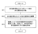
- the method for producing a gas diffusion layer used in a fuel cell Create two sheet-like porous members with different porosities, A porous member having a low porosity is placed in a mold having a protrusion corresponding to the shape of the gas flow path after the porous member having a low porosity out of the two porous members thus prepared. Forming a gas flow path on one main surface of the member; The porous member having a high porosity is laminated and bonded to the other main surface of the porous member having a low porosity forming the gas flow path.
- the manufacturing method of the gas diffusion layer for fuel cells is provided.
- a method for producing a gas diffusion layer used in a fuel cell Create two sheet-like porous members with different porosities, Laminating the two porous members produced above, The stacked two porous members are placed in a mold having a protrusion corresponding to the shape of the gas flow path so that the porous member having a low porosity faces the protrusion, and then rolled. Forming a gas flow path on one main surface of the porous member having a low porosity, The manufacturing method of the gas diffusion layer for fuel cells is provided.
- the gas diffusion layer for a fuel cell of the present invention, has a multilayer structure including the first diffusion layer and the second diffusion layer, and the porosity of the first diffusion layer in which the gas flow path is formed is set to the first. 2 Lower than the diffusion layer. That is, the strength of the first diffusion layer is higher than that of the second diffusion layer. As a result, it is possible to prevent the gas flow paths from being blocked due to deformation of the rib portions separating the gas flow paths adjacent to each other due to pressure applied when a plurality of cells are stacked and pressure-fastened. .
- the reaction gas can flow at a constant flow rate along the shape of the gas flow channel from the upstream portion to the downstream portion of the gas flow channel.
- the porosity of the second diffusion layer is higher than that of the first diffusion layer, the reaction gas is diffused vertically below the rib portion by the gas diffusivity of the second diffusion layer, and the in-plane power generation distribution Variations can be suppressed. Therefore, the power generation performance can be further improved.
- the first and second diffusion layers are composed of a porous member mainly composed of conductive particles and a polymer resin, the cost can be reduced and a gas flow having a complicated shape can be achieved. The path can also be easily formed.
- FIG. 1 is a schematic cross-sectional view showing a basic configuration of a fuel cell according to an embodiment of the present invention.
- FIG. 2 is a schematic cross-sectional view showing a configuration of a gas diffusion layer alone according to an embodiment of the present invention.
- FIG. 3 is a flowchart showing a method for manufacturing a gas diffusion layer according to an embodiment of the present invention,
- FIG. 4A is a schematic explanatory view showing a method for producing a gas diffusion layer according to an embodiment of the present invention.
- FIG. 4B is a schematic explanatory diagram illustrating a process following FIG. 4A.
- FIG. 4C is a schematic explanatory diagram illustrating a process following FIG. 4B.
- FIG. 5 is a flowchart showing another manufacturing method of the gas diffusion layer according to the embodiment of the present invention.
- FIG. 6A is a schematic explanatory view showing another method of manufacturing the gas diffusion layer according to the embodiment of the present invention
- FIG. 6B is a schematic explanatory diagram illustrating a process following FIG. 6A.
- FIG. 6C is a schematic explanatory view showing a process following FIG. 6B.
- FIG. 7 is a schematic cross-sectional view showing a modification of the basic configuration of the fuel cell according to the embodiment of the present invention.
- FIG. 8 is a schematic cross-sectional view showing the configuration of a conventional fuel cell.
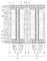
- FIG. 1 is a schematic cross-sectional view showing a basic configuration of a fuel cell according to an embodiment of the present invention.
- the fuel cell according to the present embodiment is a polymer electrolyte type that generates electric power and heat simultaneously by electrochemically reacting a fuel gas containing hydrogen and an oxidant gas containing oxygen such as air. It is a fuel cell.
- the present invention is not limited to the polymer electrolyte fuel cell, and can be applied to various fuel cells.
- the fuel cell according to the present embodiment includes a membrane electrode assembly 10 (hereinafter referred to as MEA) and a pair of conductive plate current collectors 20A and 20C that are disposed on both sides of the MEA 10 and have conductivity.
- a cell (unit cell) 1 is provided.
- the fuel cell according to the present embodiment may be configured by stacking a plurality of the cells 1. In this case, the stacked cells 1 are fastened with a predetermined fastening pressure by a fastening member (not shown) such as a bolt so that the fuel gas and the oxidant gas do not leak and the contact resistance is reduced. It is preferred that
- the MEA 10 includes a polymer electrolyte membrane 11 that selectively transports hydrogen ions and a pair of electrode layers formed on both surfaces of the polymer electrolyte membrane 11.
- One of the pair of electrode layers is an anode electrode (also referred to as a fuel electrode) 12A, and the other is a cathode electrode (also referred to as an air electrode) 12C.
- the anode electrode 12A is formed on one surface of the polymer electrolyte membrane 11, and is formed on the anode catalyst layer 13A and a pair of anode catalyst layers 13A mainly composed of carbon powder carrying a white metal catalyst.
- an anode gas diffusion layer 14A having both current collecting action, gas permeability and water repellency.
- the cathode electrode 12C is formed on the other surface of the polymer electrolyte membrane 11, and is formed on the cathode catalyst layer 13C and a pair of cathode catalyst layers 13C mainly composed of carbon powder carrying a white metal catalyst. And a cathode gas diffusion layer 14C having both current collecting action, gas permeability and water repellency.
- the anode gas diffusion layer 14A has a multi-layer structure including a first anode diffusion layer 15A that is an example of a first diffusion layer and a second anode diffusion layer 16A that is an example of a second diffusion layer.
- the first and second anode diffusion layers 15A and 16A are formed of a base material-less gas diffusion layer that does not use carbon fiber as a base material.
- the first and second anode diffusion layers 15A and 16A are composed of a porous member mainly composed of conductive particles and a polymer resin.
- a fuel gas passage 21A for flowing fuel gas is provided on one main surface of the first anode diffusion layer 15A.
- the ends of the rib portions 22A that separate the fuel gas passages 21A, 21A adjacent to each other are in contact with the current collector plate 20A at a predetermined pressure. This prevents the fuel gas from flowing outside the fuel gas channel 21A (external leak).
- the other main surface of the first anode diffusion layer 15A is in contact with the second anode diffusion layer 16A.
- the first anode diffusion layer 15A has a lower porosity than the second anode diffusion layer 16A.
- the second anode diffusion layer 16A is in contact with the anode catalyst layer 13A.
- the cathode gas diffusion layer 14 ⁇ / b> C has a multilayer structure including a first cathode diffusion layer 15 ⁇ / b> C that is an example of a first diffusion layer and a second cathode diffusion layer 16 ⁇ / b> C that is an example of a second diffusion layer.
- the first and second cathode diffusion layers 15C and 16C are formed of a base material-less gas diffusion layer that does not use carbon fiber as a base material.
- the first and second cathode diffusion layers 15C and 16C are made of a porous member mainly composed of conductive particles and a polymer resin.
- an oxidant gas flow path 21C for flowing an oxidant gas is provided on one main surface of the first cathode diffusion layer 15C.
- the tips of the rib portions 22C separating the oxidant gas flow paths 21C and 21C adjacent to each other are in contact with the current collector plate 20C at a predetermined pressure. This prevents the oxidizing gas from flowing outside the oxidizing gas channel 21C (external leakage).
- the other main surface of the first cathode diffusion layer 15C is in contact with the second cathode diffusion layer 16C.
- the first cathode diffusion layer 15C has a lower porosity than the second cathode diffusion layer 16C.
- the second cathode diffusion layer 16C is in contact with the cathode catalyst layer 13C.
- the fuel gas is supplied to the anode electrode 12A through the fuel gas flow path 21A, and the oxidant gas is supplied to the cathode electrode 12C through the oxidant gas flow path 21C, whereby an electrochemical reaction occurs, and electric power and heat are generated. appear.
- the fastening pressure is 2 to 10 kgf / cm 2. Is preferred.
- the fastening pressure is larger than 10 kgf / cm 2 , the rib portions 22A and 22C are easily deformed.
- the fastening pressure is smaller than 2 kgf / cm 2 , the contact resistance between the members increases rapidly, or the fuel gas or the oxidant gas hardly flows along the fuel gas channel 21A or the oxidant gas channel 21C. Become.
- the current collector plates 20A and 20C are made of a material such as a metal having low gas permeability.
- current collector plates 20A and 20C are made of a material such as carbon or metal having excellent corrosion resistance, conductivity, gas impermeability, and flatness.
- the current collector plates 20A and 20C may be provided with a cooling water flow path (not shown) through which cooling water or the like passes.
- an anode gasket 17A is provided as a sealing material so as to cover the side surfaces of the anode catalyst layer 13A and the anode gas diffusion layer 14A.
- a cathode is used as a sealing material so as to cover the side surfaces of the cathode catalyst layer 13C and the cathode gas diffusion layer 14C.
- a gasket 17C is disposed.
- thermoplastic resin thermosetting resin, or the like
- materials for the anode gasket 17A and the cathode gasket 17C silicon resin, epoxy resin, melamine resin, polyurethane resin, polyimide resin, acrylic resin, ABS resin, polypropylene, liquid crystalline polymer, polyphenylene sulfide resin, polysulfone, glass fiber A reinforced resin or the like can be used.
- the anode gasket 17A and the cathode gasket 17C are preferably partially impregnated in the periphery of the anode gas diffusion layer 14A or the cathode gas diffusion layer 14C. Thereby, power generation durability and strength can be improved.
- a gasket is provided between the current collector plate 20A and the current collector plate 20C so as to cover the side surfaces of the polymer electrolyte membrane 11, the anode electrode 12A, and the cathode electrode 12C. You may arrange. Thereby, deterioration of the polymer electrolyte membrane 11 can be suppressed, and handling of the MEA 10 and workability during mass production can be improved.
- the configuration of the anode gas diffusion layer 14A and the cathode gas diffusion layer 14C according to this embodiment will be described in more detail.
- the anode gas diffusion layer 14A and the cathode gas diffusion layer 14C have the same configuration unless otherwise specified. For this reason, when the matters common to these are described, these are simply referred to as the gas diffusion layer 14.
- the first anode diffusion layer 15A and the first cathode diffusion layer 15C are referred to as the first diffusion layer 15, and the second anode diffusion layer 16A and the second cathode diffusion layer 16C are referred to as the second diffusion layer 16.
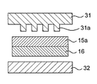
- FIG. 2 is a schematic cross-sectional view showing a configuration of a gas diffusion layer alone.
- the gas diffusion layer 14 has the following three functions.
- the first is a gas diffusive function that diffuses the reaction gas flowing from the gas flow path 21 not only vertically below the gas flow path 21 but also vertically below the rib portion 22.
- the second is a water management function that discharges excess water while appropriately moistening the inside of the catalyst layer.
- the third is a current collecting function that forms an electron transfer path.
- the gas diffusion layer 14 has a two-layer structure including a first diffusion layer 15 and a second diffusion layer 16.
- the first and second diffusion layers 15 and 16 are each composed of a sheet-like and rubber-like porous member mainly composed of conductive particles and a polymer resin.
- the porosity of the first diffusion layer 15 is set lower than the porosity of the second diffusion layer 16.
- the porosity of the first and second diffusion layers 15 and 16 can be changed by varying the composition of the material used, the rolling force applied during production, the number of rolling operations, and the like.
- the porosity of the first diffusion layer 15 is preferably 20% or more and less than 50%.
- the porosity of the first diffusion layer 15 is less than 20%, the gas permeability is lowered and the reaction gas does not reach not only vertically below the rib portion 22 but also vertically below the gas flow path 21. The power generation performance is significantly reduced.
- the porosity of the 1st diffused layer 15 is 50% or more, intensity
- the porosity of the second diffusion layer 16 is preferably 65% or more and less than 80%.
- the porosity of the second diffusion layer 16 is less than 65%, the gas permeability decreases, the reaction gas does not flow easily in the thickness direction, and power generation vertically below the rib portion 22 becomes difficult.
- Examples of the material of the conductive particles constituting the first and second diffusion layers 15 and 16 include carbon materials such as graphite, carbon black, and activated carbon.
- Examples of carbon black include acetylene black (AB), furnace black, ketjen black, and vulcan. Of these, acetylene black is preferably used as the main component of carbon black from the viewpoint of low impurity content and high electrical conductivity.
- natural graphite, artificial graphite, etc. are mentioned as a main component of graphite. Among these, artificial graphite is preferably used as the main component of graphite from the viewpoint of a small amount of impurities.
- a raw material form of a carbon material powder form, fibrous form, granular form, etc. are mentioned, for example. Among these, it is preferable from the viewpoint of dispersibility and handleability that the powder form is adopted as the raw material form of the carbon material.
- the conductive particles contained in the first diffusion layer 15 are preferably configured by mixing two types of carbon materials having different average particle diameters. Thereby, since a particle with a small average particle diameter can enter into a gap between particles with a large average particle diameter, the entire porosity of the first diffusion layer 15 is reduced (for example, 60% or less). It becomes easy.
- acetylene black is used as one carbon material
- artificial graphite is an example of the other carbon material that can easily form a filling structure.
- the conductive particles are configured by mixing three or more types of carbon materials, it is easy to configure a filling structure.
- the conductive particles are more preferably configured by mixing two types of carbon materials.
- the mixing ratio (weight ratio) thereof is preferably 0.3 or more for artificial graphite with respect to 1 for acetylene black.
- the second diffusion layer 16 needs to have a high porosity, so that the conductive particles contained in the second diffusion layer 16 are made of one kind of carbon material. Is preferred. Moreover, it is preferable that the one type of carbon material has little variation in particle diameter. Further, the conductive particles contained in the second diffusion layer 16 may be composed of two or more types of carbon materials having different average particle diameters, like the first diffusion layer 15. However, in this case, it is preferable to adjust the blending ratio of each carbon material so that the filling structure is not formed. For example, when the conductive particles are configured by mixing acetylene black and artificial graphite, the blending ratio (weight ratio) thereof is preferably 1 for acetylene black and less than 0.3 for artificial graphite.
- the polymer resin constituting the first and second diffusion layers 15 and 16 has a function as a binder for binding the conductive particles to each other. Further, since the polymer resin has water repellency, it also has a function (water retention) for confining water in the system inside the fuel cell. The lower the composition ratio of the polymer resin, the higher the hydrophilicity of the gas diffusion layer itself. When the hydrophilicity in the vicinity of the gas flow path 21 is high, it becomes easy to discharge condensed water to the outside of the system. For this reason, it is preferable that the blend ratio of the polymer resin is lower in the first diffusion layer 15 than in the second diffusion layer 16. In addition, since the polymer resin is non-conductive, the contact resistance between the rib portion 22 and the current collector plates 20A and 20C can be reduced by reducing the blending ratio of the polymer resin in the first diffusion layer 15. it can.
- PTFE polytetrafluoroethylene
- FEP tetrafluoroethylene / hexafluoropropylene copolymer
- PVDF polyvinylidene fluoride
- ETFE tetrafluoroethylene / ethylene copolymer
- PCTFE polychlorotrifluoroethylene
- PFA tetrafluoroethylene / perfluoroalkyl vinyl ether copolymer
- the raw material form of PTFE include dispersion and powder. Among these, it is preferable from the viewpoint of workability that the dispersion is adopted as a raw material form of PTFE.
- the shape (pattern) of the gas flow path 21 formed in the first diffusion layer 15 is not particularly limited, and can be formed in the same manner as the shape of the gas flow path formed in the conventional separator.
- Examples of the shape of such a gas flow path include a straight type and a serpentine type.
- the optimum value of the width of the gas flow path 21 varies greatly depending on the electrode area, gas flow rate, current density, humidification conditions, cell temperature, etc., but within the range of 0.1 mm to 3.0 mm, particularly 0.2 mm to 1.5 mm. It is preferable to be within the range.
- the width of the gas flow path 21 is less than 0.1 mm, there is a possibility that the width of the gas flow path 21 is not sufficient with respect to the amount of reaction gas normally flowed in the fuel cell.
- the width of the gas flow path 21 is larger than 3.0 mm, the reaction gas may not flow through the entire gas flow path 21, and the reaction gas may stay and flooding may occur.
- the depth of the gas flow path 21 varies greatly depending on the electrode area, gas flow rate, current density, humidification conditions, cell temperature, etc., but is in the range of 0.015 mm to 2.0 mm, particularly 0.03 mm to 0.8 mm. It is preferable to be within. If the depth of the gas flow path 21 is less than 0.015 mm, the depth of the gas flow path 21 may not be sufficient with respect to the amount of reaction gas that normally flows in the fuel cell. On the other hand, when the depth of the gas flow path 21 is larger than 2,0 mm, the reaction gas may not flow through the entire gas flow path 21, and the reaction gas may stay and flooding may occur.
- the width of the rib portion 22 formed in the first diffusion layer 15 is preferably within a range of 0.1 mm to 3.0 mm, particularly preferably within a range of 0.2 mm to 2.0 mm.
- the width of the rib portion 22 is less than 0.1 mm, the strength is reduced and the gas flow path 21 is easily deformed.
- the width of the rib portion 22 is larger than 2.0 mm, the area vertically below the rib portion 22 is increased, so that the reaction gas is not uniformly diffused in the first diffusion layer 15 and the in-plane power generation distribution. There is a risk of variation.
- the optimum value of the thickness of the second diffusion layer 16 varies greatly depending on the gas utilization rate, current density, humidification conditions, cell temperature, etc., but is in the range of 0.05 mm to 1.0 mm, particularly 0.1 mm to 0.4 mm. It is preferable to be within the range.
- the ratio of the thickness of the second diffusion layer 16 to the first diffusion layer 15 is preferably in the range of 0.3 to 2.0.
- the ratio of the thickness of the second diffusion layer 16 to the first diffusion layer 15 is less than 0.3, the gas diffusibility in the thickness direction is reduced, and the reaction gas reaches vertically below the rib portion 22. Disappear. As a result, the in-plane power generation distribution varies, and the power generation performance decreases.
- the ratio of the thickness of the second diffusion layer 16 to the first diffusion layer 15 is larger than 2.0, the entire gas diffusion layer 14 becomes too thick, so that the reaction gas becomes the catalyst layer 13A, At the same time, the electric resistance increases and the power generation performance decreases.
- the 1st and 2nd diffused layers 15 and 16 should just be a structure (so-called self-supporting body structure) supported by electroconductive particle and polymer resin, without using a carbon fiber as a base material. Therefore, the first and second diffusion layers 15 and 16 may contain a trace amount of a surfactant and a dispersion solvent used in manufacturing the gas diffusion layer, in addition to the conductive particles and the polymer resin.
- a dispersion solvent include water, alcohols such as methanol and ethanol, and glycols such as ethylene glycol.
- the surfactant include nonionic compounds such as polyoxyethylene alkyl ethers and zwitterionic compounds such as alkylamine oxides.
- the conductive particles and the polymer resin tend to be uniformly dispersed, while the fluidity increases, and the gas diffusion layer It tends to be difficult to make a sheet.
- the first and second diffusion layers 15 and 16 may contain carbon fibers having a weight that does not hold as a base material (for example, a weight less than that of the conductive particles and the polymer resin). Since carbon fibers have a reinforcing effect, a high-strength gas diffusion layer can be produced by increasing the blending ratio of carbon fibers.
- the first diffusion layer 15 needs to have higher strength than the second diffusion layer 16 in order to suppress deformation of the rib portion 22. For this reason, it is preferable that the first diffusion layer 15 has a higher carbon fiber blending ratio than the second diffusion layer 16. Since the first diffusion layer 15 becomes highly conductive by increasing the blending ratio of the carbon fibers of the first diffusion layer 15, the contact resistance between the rib portion 22 and the current collector plates 20A and 20C can also be reduced. .
- Examples of the carbon fiber material include vapor grown carbon fiber (hereinafter referred to as VGCF), milled fiber, cut fiber, and chop fiber.
- VGCF vapor grown carbon fiber
- milled fiber, cut fiber, and chop fiber examples of the carbon fiber material.
- VGCF vapor grown carbon fiber
- milled fiber, cut fiber, or chop fiber is used as the carbon fiber, for example, a fiber having a fiber diameter of 5 to 20 ⁇ m and a fiber length of 20 to 100 ⁇ m may be used.
- the raw material of the milled fiber, cut fiber, or chop fiber may be PAN, pitch, or rayon.
- the fiber is preferably used by dispersing a bundle of short fibers produced by cutting and cutting an original yarn (long fiber filament or short fiber stable).
- the amount of the carbon fiber is preferably less than that of the polymer resin. Adding a small amount of carbon fiber is also effective for increasing the strength of the baseless gas diffusion layer.
- the blending amount of the carbon fiber is larger than that of the polymer resin, there is a concern that the carbon fiber pierces the film and the film deteriorates to deteriorate the performance. Moreover, it becomes a factor which becomes high in cost.
- the first and second diffusion layers 15 and 16 do not need to use carbon fibers as a base material, and may have a self-supporting structure supported by conductive particles, a polymer resin, and carbon fibers.
- the porosity of the second anode gas diffusion layer 16A of the anode gas diffusion layer 14A is preferably lower than the porosity of the second cathode gas diffusion layer 16C of the cathode gas diffusion layer 14C.
- the water retention of 16 A of 2nd anode gas diffusion layers can be made high compared with the water retention of 16 C of 2nd cathode gas diffusion layers.
- the gas diffusibility of the second cathode gas diffusion layer 16C can be made higher than the gas diffusivity of the second anode gas diffusion layer 16A.
- FIG. 3 is a flowchart showing a method for manufacturing a gas diffusion layer according to an embodiment of the present invention.
- 4A to 4C are schematic explanatory views thereof.
- step S1 two sheet-like porous members having different porosities are produced.
- the sheet-like porous member can be produced, for example, as follows.
- a polymer resin material is added and dispersed in the kneaded product.
- the carbon material and the polymer resin material may not be separately charged into the kneading machine, but all the materials may be simultaneously charged into the kneading machine.
- the kneaded material obtained by kneading is rolled into a sheet by a roll press or a flat plate press.
- the kneaded product formed into a sheet is baked to remove the surfactant and the dispersion solvent from the kneaded product.
- the firing temperature and firing time are preferably the temperature and time at which the surfactant and the dispersion solvent evaporate or decompose.
- the kneaded product from which the surfactant and the dispersion solvent have been removed is re-rolled to adjust the thickness. Thereby, a sheet-like porous member can be produced.
- Two sheet-like porous members having different porosities can be manufactured by changing the conductive particles to be used, the rolling force by a press, the number of rolling operations, and the like in the production process.
- a porous member having a high porosity one type of carbon material is used, and when producing a porous member having a low porosity, two types of carbon materials having different average particle diameters are used. That's fine. Thereby, two porous members having different porosities can be obtained.
- the porosity of the two porous members can be increased by increasing the rolling force or the number of rolling operations with a press compared to when producing a porous member with high porosity. The difference can be increased.
- the one having the gas flow path 21 formed on the porous member having a low porosity is the first diffusion layer 15, and the porous member having a high porosity is the first porous member. 2 diffusion layers 16 are formed.
- the porous member before the formation of the gas flow path 21 is referred to as a porous member 15a.
- the kneaded material is rolled with a roll press or a flat plate press to produce a sheet-like porous member, but the present invention is not limited to this.
- the kneaded material can be put into an extruder and sheet-formed continuously from the die head of the extruder to produce a sheet-like porous member.
- the kneaded product can be obtained without using the kneader by devising the shape of the screw provided in the extruder and giving the screw a kneading function. That is, stirring, kneading, and sheet forming of each carbon material can be performed integrally with a single machine.
- step S2 as shown in FIGS. 4A and 4B, the low-porosity porous member 15a is disposed in a pair of molds 31 and 32 having protrusions 31a corresponding to the shape of the gas flow path 21.
- the molds 31 and 32 are closed with a rolling machine and rolled.
- the gas flow path 21 is formed in the porous member 15a having a low porosity, and the first diffusion layer 15 can be obtained.
- dies 31 and 32 may be comprised integrally with a rolling machine, it is easier to handle the one comprised so that attachment or detachment to a rolling machine is possible.
- a rolling machine a roll press machine or a flat plate press machine can be used.
- die 31 and 32 which has the projection part 31a is directly formed in the surface of a roll.
- the heating temperature is preferably 250 ° C. or lower.
- the porous member 15a having a low porosity is softened and the formation of the gas flow path 21 is facilitated.
- the heating temperature is higher than 250 ° C., the porous member 15a having a low porosity may be deteriorated.
- the rolling force of the rolling machine is preferably less than 500 kgf / cm 2 . The higher the rolling force of the rolling machine, the easier the gas channel 21 can be formed. However, if a rolling force of 500 kgf / cm 2 or more is applied to the porous member 15a having a low porosity, there is a risk of cracking or material destruction. There is.
- a mold release agent may be applied in advance in order to prevent the molds 31 and 32 and the porous member 15a having a low porosity from coming into close contact after rolling by a rolling machine.
- the mold release agent can be selected as appropriate as long as it does not affect the power generation performance of the fuel cell, but it is preferable to use distilled water or surfactant-diluted distilled water.
- a sheet made of PTFE resin may be used in place of the release agent.
- the materials of the molds 31 and 32 can be selected from stainless steel, nickel chrome molybdenum steel, cemented carbide steel, SKD11, SKD12, tool steel such as Ni-P hardened chromium, ceramics, glass fiber reinforced plastic, and the like.
- the surfaces of the dies 31 and 32 may be subjected to surface treatment such as hard Cr plating, PVD coating, TiC coating, TD treatment, Zr spraying treatment, PTFE coating, etc., in order to improve the corrosion resistance and release properties. .
- surface treatment such as hard Cr plating, PVD coating, TiC coating, TD treatment, Zr spraying treatment, PTFE coating, etc.
- step S3 as shown in FIG. 4C, the first diffusion layer 15 and the second diffusion layer 16 produced as described above are stacked and bonded together by the flat plate press 33. At this time, the second diffusion layer 16 is bonded to the main surface of the first diffusion layer 15 opposite to the gas flow path forming surface. Thereby, the gas diffusion layer 14 shown in FIG. 2 can be obtained.
- the gas diffusion layer 14 is prevented from warping (waving) in the thickness direction. Can do.
- the flat plate press machine 33 it is preferable to perform bonding by the flat plate press machine 33 with a surface pressure of 2 kg / cm 2 or less.
- the surface pressure is larger than 2 kg / cm 2 , the rib portion 22 may be deformed and the gas flow path 21 may be narrowed.
- first diffusion layer 15 and the second diffusion layer 16 may be performed using a conductive adhesive mainly composed of a conductive filler and a binder.
- the first diffusion layer 15 and the second diffusion layer 16 are bonded to each other using a dispersion solution (for example, Nafion (registered trademark) manufactured by DuPont) containing a similar component to the polymer electrolyte membrane 11 or a small amount of distilled water. You may go.
- a dispersion solution for example, Nafion (registered trademark) manufactured by DuPont
- the gas diffusion layer 14 is manufactured by performing the steps S1 to S3.
- the present invention is not limited to this. For example, other operations may be appropriately included between the steps.
- step S3 the first diffusion layer 15 and the second diffusion layer 16 are stacked and bonded together by the flat plate press 33, but the present invention is not limited to this.
- the second diffusion layer 16 may be disposed between the first diffusion layer 15 and the mold 32, and the molds 31 and 32 may be closed with a rolling machine and bonded together.
- the molds 31 and 32 are closed with a rolling machine and rolled to obtain the first diffusion layer 15.
- the second diffusion layer 16 is disposed between the main surface of the first diffusion layer 15 opposite to the gas flow path forming surface and the mold 32, and the first diffusion layer 15 and the second diffusion layer 15 are disposed.
- the diffusion layer 16 may be laminated, and the molds 31 and 32 may be closed and bonded together using a rolling machine.
- the step of removing the first diffusion layer 15 from the mold 31 after the step 2 by using the molds 31 and 32 for bonding the first diffusion layer 15 and the second diffusion layer 16. Can be omitted.
- FIG. 5 is a flowchart showing another method of manufacturing the gas diffusion layer.
- 6A to 6C are schematic explanatory views thereof.
- step S11 two sheet-like porous members having different porosities are produced in the same manner as in step S1.
- step S12 as shown in FIG. 6A, a porous member 15a having a low porosity and a second diffusion layer 16 that is a porous member having a high porosity are laminated.
- step S13 the laminate of the porous member 15a having a low porosity and the second diffusion layer 16 is pressurized. Therefore, in step S12, the porous member 15a having a low porosity and the second diffusion layer 16 are pressed. Are simply laminated.
- the porous member 15a having a low porosity and the second diffusion layer 16 may be bonded in advance using the flat plate press 33, the conductive adhesive, the dispersion solvent, distilled water, or the like as described above. .
- step S13 the bonded porous member 15a having a low porosity and the second diffusion layer 16 are disposed in the dies 31, 32. At this time, it arrange
- the flat plate press 33 is used to press the gas diffusion layer 14 with a surface pressure of 2 kg / cm 2 or less. do it.
- the gas diffusion layer 14 has the two-layer structure including the first diffusion layer 15 and the second diffusion layer 16, and the first diffusion in which the gas flow path 21 is formed.
- the porosity of the layer 15 is lower than that of the second diffusion layer 16. That is, the strength of the first diffusion layer 15 is higher than that of the second diffusion layer 16.
- the ribs 22 separating the gas flow paths 21 adjacent to each other are deformed by the pressure applied when the plurality of cells 1 are stacked and fastened, and the gas flow paths 21 are blocked. Can be suppressed.
- the reaction gas can be prevented from passing through the inside of the rib portion 22, and the reaction gas can flow at a constant flow rate along the shape of the gas flow channel 21 from the upstream portion to the downstream portion of the gas flow channel 21. it can.
- the porosity of the second diffusion layer 16 is higher than that of the first diffusion layer 15, the reaction gas is diffused vertically below the rib portion 22 due to the gas diffusibility of the second diffusion layer 16. Variations in internal power distribution can be suppressed. Therefore, the power generation performance can be further improved.
- the first and second diffusion layers 15 and 16 are made of a porous member mainly composed of conductive particles and a polymer resin, the cost can be reduced and a complicated shape can be achieved. This gas flow path can also be easily formed.
- the gas diffusion layer 14 having a two-layer structure according to the present invention is disposed on both the anode side and the cathode side, but the present invention is not limited to this.
- the gas diffusion layer 14 having a two-layer structure according to the present invention may be arranged on at least one of the anode side and the cathode side.
- the power generation performance of the fuel cell tends to be higher when the oxidant gas flow path of the cathode electrode (air electrode) has a more complicated shape than the fuel gas flow path of the anode electrode (fuel electrode).
- the 1st diffusion layer concerning the present invention comprises a substrate less gas diffusion layer, formation of a gas channel is easy. Therefore, for example, as shown in FIG. 7, an anode gas diffusion layer 214A having a normal single layer structure and a normal separator 220A provided with a fuel gas flow path 221A are arranged on the anode side, and only on the cathode side.
- the cathode gas diffusion layer 14C having a two-layer structure having the oxidant gas flow path 21C and the current collector plate 21C may be disposed. Also with such a configuration, the power generation performance of the fuel cell can be further improved as compared with the conventional configuration.
- the porosity of the anode gas diffusion layer 214A is preferably lower than the porosity of the second cathode gas diffusion layer 16C of the cathode gas diffusion layer 14C.
- the water retention of the anode gas diffusion layer 214A can be made higher than that of the second cathode gas diffusion layer 16C.
- the gas diffusivity of the second cathode gas diffusion layer 16C can be made higher than the gas diffusivity of the anode gas diffusion layer 214A.
- the fuel cell gas diffusion layer and the manufacturing method thereof, and the fuel cell according to the present invention can further improve the power generation performance in the gas diffusion layer in which the gas flow path is formed on one main surface. It is useful for a fuel cell used as a driving source for a moving body such as an automobile, a distributed power generation system, and a cogeneration system for home use.
Abstract
Description
本発明の第1態様によれば、燃料電池に用いるガス拡散層において、
前記ガス拡散層は、
一方の主面にガス流路が形成された第1拡散層と、
前記第1拡散層の他方の主面上に積層された第2拡散層と、
を有する複層構造で構成され、
前記第1及び第2拡散層は、導電性粒子と高分子樹脂とを主成分とした多孔質部材で構成され、
前記第1拡散層の多孔度は、前記第2拡散層の多孔度よりも低い、
燃料電池用ガス拡散層を提供する。 In order to achieve the above object, the present invention is configured as follows.
According to the first aspect of the present invention, in the gas diffusion layer used in the fuel cell,
The gas diffusion layer is
A first diffusion layer having a gas flow path formed on one main surface;
A second diffusion layer laminated on the other main surface of the first diffusion layer;
A multi-layer structure having
The first and second diffusion layers are composed of a porous member mainly composed of conductive particles and a polymer resin,
The porosity of the first diffusion layer is lower than the porosity of the second diffusion layer;
A gas diffusion layer for a fuel cell is provided.
前記高分子電解質膜を挟んで互いに対向する一対の触媒層と、
前記高分子電解質膜及び前記一対の触媒層を挟んで互いに対向する一対のガス拡散層と、
前記高分子電解質膜、前記一対の触媒層、及び一対のガス拡散層を挟んで互いに対向する一対の集電板と、
を備える燃料電池において、
前記一対のガス拡散層の少なくとも一方は、第1~8態様のいずれか1つに記載のガス拡散層であり、
前記第1拡散層が前記集電板に接し、前記第2拡散層が前記触媒層に接している、
燃料電池を提供する。 According to a ninth aspect of the present invention, a polymer electrolyte membrane;
A pair of catalyst layers facing each other across the polymer electrolyte membrane;
A pair of gas diffusion layers facing each other across the polymer electrolyte membrane and the pair of catalyst layers;
A pair of current collector plates facing each other across the polymer electrolyte membrane, the pair of catalyst layers, and the pair of gas diffusion layers;
In a fuel cell comprising:
At least one of the pair of gas diffusion layers is the gas diffusion layer according to any one of the first to eighth aspects,
The first diffusion layer is in contact with the current collector plate, and the second diffusion layer is in contact with the catalyst layer;
A fuel cell is provided.
前記高分子電解質膜の一方の主面上に形成されたアノード触媒層と、
前記アノード触媒層上に積層されたアノードガス拡散層と、
前記アノードガス拡散層上に積層され、前記アノードガス拡散層に接する主面にガス流路が形成されたセパレータと、
前記高分子電解質膜の他方の主面上に形成されたカソード触媒層と、
前記カソード触媒層上に積層されたカソードガス拡散層と、
前記カソードガス拡散層上に積層された集電板と、
を備え、
前記カソードガス拡散層は、第1~8態様のいずれか1つに記載のガス拡散層であり、
前記第1拡散層が前記集電板に接し、前記第2拡散層が前記触媒層に接している、
燃料電池を提供する。 According to a tenth aspect of the present invention, a polymer electrolyte membrane;
An anode catalyst layer formed on one main surface of the polymer electrolyte membrane;
An anode gas diffusion layer laminated on the anode catalyst layer;
A separator laminated on the anode gas diffusion layer and having a gas flow path formed on a main surface in contact with the anode gas diffusion layer;
A cathode catalyst layer formed on the other main surface of the polymer electrolyte membrane;
A cathode gas diffusion layer laminated on the cathode catalyst layer;
Current collectors laminated on the cathode gas diffusion layer;
With
The cathode gas diffusion layer is the gas diffusion layer according to any one of the first to eighth aspects,
The first diffusion layer is in contact with the current collector plate, and the second diffusion layer is in contact with the catalyst layer;
A fuel cell is provided.
多孔度が異なる2つのシート状の多孔質部材をそれぞれ作製し、
前記作製した2つの多孔質部材のうち多孔度が低い多孔質部材を、ガス流路の形状に対応する突起部を有する金型内に配置した後、圧延して、当該多孔度が低い多孔質部材の一方の主面にガス流路を形成し、
前記ガス流路を形成した多孔度が低い多孔質部材の他方の主面に、前記多孔度が高い多孔質部材を積層して貼り合わせる、
ことを含む、燃料電池用ガス拡散層の製造方法を提供する。 According to an eleventh aspect of the present invention, in the method for producing a gas diffusion layer used in a fuel cell,
Create two sheet-like porous members with different porosities,
A porous member having a low porosity is placed in a mold having a protrusion corresponding to the shape of the gas flow path after the porous member having a low porosity out of the two porous members thus prepared. Forming a gas flow path on one main surface of the member;
The porous member having a high porosity is laminated and bonded to the other main surface of the porous member having a low porosity forming the gas flow path.
The manufacturing method of the gas diffusion layer for fuel cells is provided.
多孔度が異なる2つのシート状の多孔質部材をそれぞれ作製し、
前記作製した2つの多孔質部材を積層し、
前記積層した2つの多孔質部材を、ガス流路の形状に対応する突起部を有する金型内に、多孔度が低い多孔質部材側が前記突起部に対向するように配置した後、圧延して、当該多孔度が低い多孔質部材の一方の主面にガス流路を形成する、
ことを含む、燃料電池用ガス拡散層の製造方法を提供する。 According to a twelfth aspect of the present invention, in a method for producing a gas diffusion layer used in a fuel cell,
Create two sheet-like porous members with different porosities,
Laminating the two porous members produced above,
The stacked two porous members are placed in a mold having a protrusion corresponding to the shape of the gas flow path so that the porous member having a low porosity faces the protrusion, and then rolled. Forming a gas flow path on one main surface of the porous member having a low porosity,
The manufacturing method of the gas diffusion layer for fuel cells is provided.
図1は、本発明の実施形態にかかる燃料電池の基本構成を示す模式断面図である。本実施形態にかかる燃料電池は、水素を含有する燃料ガスと、空気などの酸素を含有する酸化剤ガスとを電気化学的に反応させることにより、電力と熱とを同時に発生させる高分子電解質形燃料電池である。なお、本発明は高分子電解質形燃料電池に限定されるものではなく、種々の燃料電池に適用可能である。 <Embodiment>
FIG. 1 is a schematic cross-sectional view showing a basic configuration of a fuel cell according to an embodiment of the present invention. The fuel cell according to the present embodiment is a polymer electrolyte type that generates electric power and heat simultaneously by electrochemically reacting a fuel gas containing hydrogen and an oxidant gas containing oxygen such as air. It is a fuel cell. The present invention is not limited to the polymer electrolyte fuel cell, and can be applied to various fuel cells.
シート状の多孔質部材は、例えば、以下のようにして作製することができる。 First, in step S1, two sheet-like porous members having different porosities are produced.
The sheet-like porous member can be produced, for example, as follows.
まず、ガス拡散層を構成する各材料の真密度と組成比率から、製造したガス拡散層の見かけ真密度を算出する。
次いで、製造したガス拡散層の重量、厚さ、縦横寸法を測定して、製造したガス拡散層の密度を算出する。
次いで、多孔度=(ガス拡散層の密度)/(見かけ真密度)×100の式に、前記算出したガス拡散層の密度及び見かけ真密度を代入し、多孔度を算出する。
以上のようにして、製造したガス拡散層の多孔度を測定することができる。
なお、製造したガス拡散層の細孔径分布を、水銀ポロシメータを用いて測定したところ、累積細孔量から算出できる多孔度と、前記のようにして算出した多孔度とが一致していることを確認している。 In the present invention, the porosity can be measured as follows.
First, the apparent true density of the manufactured gas diffusion layer is calculated from the true density and composition ratio of each material constituting the gas diffusion layer.
Next, the weight, thickness, vertical and horizontal dimensions of the manufactured gas diffusion layer are measured, and the density of the manufactured gas diffusion layer is calculated.
Next, the porosity is calculated by substituting the calculated density of the gas diffusion layer and the apparent true density into the formula of porosity = (density of the gas diffusion layer) / (apparent true density) × 100.
As described above, the porosity of the produced gas diffusion layer can be measured.
When the pore size distribution of the produced gas diffusion layer was measured using a mercury porosimeter, it was confirmed that the porosity calculated from the cumulative pore volume was consistent with the porosity calculated as described above. I have confirmed.
Claims (12)
- 燃料電池に用いるガス拡散層において、
前記ガス拡散層は、
一方の主面にガス流路が形成された第1拡散層と、
前記第1拡散層の他方の主面上に積層された第2拡散層と、
を有する複層構造で構成され、
前記第1及び第2拡散層は、導電性粒子と高分子樹脂とを主成分とした多孔質部材で構成され、
前記第1拡散層の多孔度は、前記第2拡散層の多孔度よりも低い、
燃料電池用ガス拡散層。 In gas diffusion layers used in fuel cells,
The gas diffusion layer is
A first diffusion layer having a gas flow path formed on one main surface;
A second diffusion layer laminated on the other main surface of the first diffusion layer;
A multi-layer structure having
The first and second diffusion layers are composed of a porous member mainly composed of conductive particles and a polymer resin,
The porosity of the first diffusion layer is lower than the porosity of the second diffusion layer;
Gas diffusion layer for fuel cells. - 前記第1及び第2拡散層は、導電性粒子と高分子樹脂とを主成分とし、前記高分子樹脂よりも少ない重量の炭素繊維が添加された多孔質部材で構成されている、請求項1に記載の燃料電池用ガス拡散層。 The said 1st and 2nd diffused layer is comprised with the porous member to which the carbon fiber of the weight which has electroconductive particle and polymer resin as a main component and was less than the said polymer resin was added. A gas diffusion layer for a fuel cell according to 1.
- 前記炭素繊維は、気相成長法炭素繊維、ミルドファイバー、チョップファイバーのうちのいずれか1つである、請求項2に記載の燃料電池用ガス拡散層。 3. The gas diffusion layer for a fuel cell according to claim 2, wherein the carbon fiber is any one of vapor grown carbon fiber, milled fiber, and chop fiber.
- 前記第2拡散層よりも前記第1拡散層の方が、前記炭素繊維の組成比率が高い、請求項2又は3に記載の燃料電池用ガス拡散層。 The gas diffusion layer for a fuel cell according to claim 2 or 3, wherein the composition ratio of the carbon fiber is higher in the first diffusion layer than in the second diffusion layer.
- 前記第1拡散層に含まれる前記導電性粒子は、平均粒子径が異なる2種類以上のカーボン材料で構成されている、請求項1~4のいずれか1つに記載の燃料電池用ガス拡散層。 The gas diffusion layer for a fuel cell according to any one of claims 1 to 4, wherein the conductive particles contained in the first diffusion layer are composed of two or more types of carbon materials having different average particle diameters. .
- 前記第2拡散層よりも前記第1拡散層の方が、前記高分子樹脂の組成比率が低い、請求項1~5のいずれか1つに記載の燃料電池用ガス拡散層。 The gas diffusion layer for a fuel cell according to any one of claims 1 to 5, wherein the composition ratio of the polymer resin is lower in the first diffusion layer than in the second diffusion layer.
- 前記第1拡散層の多孔度は、20%以上50%未満である、請求項1~6のいずれか1つに記載の燃料電池用ガス拡散層。 The fuel cell gas diffusion layer according to any one of claims 1 to 6, wherein the porosity of the first diffusion layer is 20% or more and less than 50%.
- 前記第2拡散層の多孔度は、65%以上80%未満である、請求項1~7のいずれか1つに記載の燃料電池用ガス拡散層。 The fuel cell gas diffusion layer according to any one of claims 1 to 7, wherein the porosity of the second diffusion layer is 65% or more and less than 80%.
- 高分子電解質膜と、
前記高分子電解質膜を挟んで互いに対向する一対の触媒層と、
前記高分子電解質膜及び前記一対の触媒層を挟んで互いに対向する一対のガス拡散層と、
前記高分子電解質膜、前記一対の触媒層、及び一対のガス拡散層を挟んで互いに対向する一対の集電板と、
を備える燃料電池において、
前記一対のガス拡散層の少なくとも一方は、請求項1~8のいずれか1つに記載のガス拡散層であり、
前記第1拡散層が前記集電板に接し、前記第2拡散層が前記触媒層に接している、
燃料電池。 A polymer electrolyte membrane;
A pair of catalyst layers facing each other across the polymer electrolyte membrane;
A pair of gas diffusion layers facing each other across the polymer electrolyte membrane and the pair of catalyst layers;
A pair of current collector plates facing each other across the polymer electrolyte membrane, the pair of catalyst layers, and the pair of gas diffusion layers;
In a fuel cell comprising:
At least one of the pair of gas diffusion layers is the gas diffusion layer according to any one of claims 1 to 8,
The first diffusion layer is in contact with the current collector plate, and the second diffusion layer is in contact with the catalyst layer;
Fuel cell. - 高分子電解質膜と、
前記高分子電解質膜の一方の主面上に形成されたアノード触媒層と、
前記アノード触媒層上に積層されたアノードガス拡散層と、
前記アノードガス拡散層上に積層され、前記アノードガス拡散層に接する主面にガス流路が形成されたセパレータと、
前記高分子電解質膜の他方の主面上に形成されたカソード触媒層と、
前記カソード触媒層上に積層されたカソードガス拡散層と、
前記カソードガス拡散層上に積層された集電板と、
を備え、
前記カソードガス拡散層は、請求項1~8のいずれか1つに記載のガス拡散層であり、
前記第1拡散層が前記集電板に接し、前記第2拡散層が前記触媒層に接している、
燃料電池。 A polymer electrolyte membrane;
An anode catalyst layer formed on one main surface of the polymer electrolyte membrane;
An anode gas diffusion layer laminated on the anode catalyst layer;
A separator laminated on the anode gas diffusion layer and having a gas flow path formed on a main surface in contact with the anode gas diffusion layer;
A cathode catalyst layer formed on the other main surface of the polymer electrolyte membrane;
A cathode gas diffusion layer laminated on the cathode catalyst layer;
Current collectors laminated on the cathode gas diffusion layer;
With
The cathode gas diffusion layer is a gas diffusion layer according to any one of claims 1 to 8,
The first diffusion layer is in contact with the current collector plate, and the second diffusion layer is in contact with the catalyst layer;
Fuel cell. - 燃料電池に用いるガス拡散層の製造方法において、
多孔度が異なる2つのシート状の多孔質部材をそれぞれ作製し、
前記作製した2つの多孔質部材のうち多孔度が低い多孔質部材を、ガス流路の形状に対応する突起部を有する金型内に配置した後、圧延して、当該多孔度が低い多孔質部材の一方の主面にガス流路を形成し、
前記ガス流路を形成した多孔度が低い多孔質部材の他方の主面に、前記多孔度が高い多孔質部材を積層して貼り合わせる、
ことを含む、燃料電池用ガス拡散層の製造方法。 In a method for producing a gas diffusion layer used in a fuel cell,
Create two sheet-like porous members with different porosities,
A porous member having a low porosity is placed in a mold having a protrusion corresponding to the shape of the gas flow path after the porous member having a low porosity out of the two porous members thus prepared. Forming a gas flow path on one main surface of the member;
The porous member having a high porosity is laminated and bonded to the other main surface of the porous member having a low porosity forming the gas flow path.
The manufacturing method of the gas diffusion layer for fuel cells including this. - 燃料電池に用いるガス拡散層の製造方法において、
多孔度が異なる2つのシート状の多孔質部材をそれぞれ作製し、
前記作製した2つの多孔質部材を積層し、
前記積層した2つの多孔質部材を、ガス流路の形状に対応する突起部を有する金型内に、多孔度が低い多孔質部材側が前記突起部に対向するように配置した後、圧延して、当該多孔度が低い多孔質部材の一方の主面にガス流路を形成する、
ことを含む、燃料電池用ガス拡散層の製造方法。 In a method for producing a gas diffusion layer used in a fuel cell,
Create two sheet-like porous members with different porosities,
Laminating the two porous members produced above,
The stacked two porous members are placed in a mold having a protrusion corresponding to the shape of the gas flow path so that the porous member having a low porosity faces the protrusion, and then rolled. Forming a gas flow path on one main surface of the porous member having a low porosity,
The manufacturing method of the gas diffusion layer for fuel cells including this.
Priority Applications (4)
| Application Number | Priority Date | Filing Date | Title |
|---|---|---|---|
| CN201080003671.3A CN102257661B (en) | 2009-09-10 | 2010-07-02 | Gas diffusion layer and process for production thereof, and fuel cell |
| JP2011516599A JP4818486B2 (en) | 2009-09-10 | 2010-07-02 | Gas diffusion layer, method for producing the same, and fuel cell |
| US13/139,022 US8790846B2 (en) | 2009-09-10 | 2010-07-02 | Gas diffusion layer and process for production thereof, and fuel cell |
| EP10815092.1A EP2477262A4 (en) | 2009-09-10 | 2010-07-02 | Gas diffusion layer and process for production thereof, and fuel cell |
Applications Claiming Priority (2)
| Application Number | Priority Date | Filing Date | Title |
|---|---|---|---|
| JP2009209033 | 2009-09-10 | ||
| JP2009-209033 | 2009-09-10 |
Publications (1)
| Publication Number | Publication Date |
|---|---|
| WO2011030489A1 true WO2011030489A1 (en) | 2011-03-17 |
Family
ID=43732172
Family Applications (1)
| Application Number | Title | Priority Date | Filing Date |
|---|---|---|---|
| PCT/JP2010/004350 WO2011030489A1 (en) | 2009-09-10 | 2010-07-02 | Gas diffusion layer and process for production thereof, and fuel cell |
Country Status (5)
| Country | Link |
|---|---|
| US (1) | US8790846B2 (en) |
| EP (1) | EP2477262A4 (en) |
| JP (2) | JP4818486B2 (en) |
| CN (1) | CN102257661B (en) |
| WO (1) | WO2011030489A1 (en) |
Cited By (6)
| Publication number | Priority date | Publication date | Assignee | Title |
|---|---|---|---|---|
| JP2013201139A (en) * | 2013-05-31 | 2013-10-03 | Dainippon Printing Co Ltd | Conductive porous layer for battery and method for manufacturing the same |
| US9406940B2 (en) | 2011-03-25 | 2016-08-02 | Dai Nippon Printing Co., Ltd. | Conductive porous layer for batteries and fabrication method for same |
| KR20160134322A (en) * | 2015-05-15 | 2016-11-23 | 삼성전자주식회사 | Metal air battery and gas diffusion layer |
| US20170162878A1 (en) * | 2014-09-29 | 2017-06-08 | Panasonic Intellectual Property Management Co., Ltd. | Gas diffusion layer for fuel cell, fuel cell, and formation method for gas diffusion layer for fuel cell |
| JP2020167059A (en) * | 2019-03-29 | 2020-10-08 | パナソニックIpマネジメント株式会社 | Membrane electrode assembly and fuel cell |
| US10903507B2 (en) * | 2015-12-28 | 2021-01-26 | Robert Bosch Gmbh | Method for producing a flow plate for a fuel cell |
Families Citing this family (26)
| Publication number | Priority date | Publication date | Assignee | Title |
|---|---|---|---|---|
| CN102257661B (en) * | 2009-09-10 | 2014-05-28 | 松下电器产业株式会社 | Gas diffusion layer and process for production thereof, and fuel cell |
| WO2013112360A1 (en) | 2012-01-27 | 2013-08-01 | University Of Kansas | Hydrophobized gas diffusion layers and method of making the same |
| JP6088048B2 (en) | 2012-06-12 | 2017-03-01 | モナシュ ユニバーシティ | Breathable electrode structure and method and system for water splitting |
| US10355283B2 (en) | 2013-07-31 | 2019-07-16 | Aquahydrez Pty Ltd | Electro-synthetic or electro-energy cell with gas diffusion electrode(s) |
| KR101620155B1 (en) | 2014-01-22 | 2016-05-12 | 현대자동차주식회사 | Fuel cell and manufacturing method thereof |
| DE102014213555A1 (en) * | 2014-07-11 | 2016-01-14 | Sgl Carbon Se | Membrane-electrode assembly |
| WO2016031226A1 (en) | 2014-08-26 | 2016-03-03 | パナソニックIpマネジメント株式会社 | Fuel cell module, fuel cell stack, and method for producing fuel cell module |
| KR102356254B1 (en) | 2014-10-17 | 2022-01-28 | 도레이 카부시키가이샤 | Carbon sheet, gas diffusion electrode base material, and fuel cell |
| WO2016157714A1 (en) | 2015-03-30 | 2016-10-06 | パナソニックIpマネジメント株式会社 | Fuel cell and method for manufacturing fuel cell |
| JP6931802B2 (en) * | 2015-11-19 | 2021-09-08 | パナソニックIpマネジメント株式会社 | Gas diffusion layer for fuel cell and its manufacturing method, membrane electrode assembly, and fuel cell |
| CN106935883B (en) * | 2015-12-31 | 2020-06-09 | 上海恒劲动力科技有限公司 | Fuel cell system |
| KR101966096B1 (en) * | 2016-09-28 | 2019-04-05 | 현대자동차 주식회사 | Fuel cell and manufacturing method of gas diffusion layer |
| CN107706436B (en) * | 2017-10-13 | 2019-04-09 | 吉林大学 | A kind of air cathode of imitative fish gill surface micro-nano structure |
| JP2019084585A (en) * | 2017-11-01 | 2019-06-06 | 木内 学 | Plate-shaped molding having fine three-dimensional surface, separator for fuel cell, manufacturing method thereof, and manufacturing facility therefor |
| WO2019207811A1 (en) * | 2018-04-28 | 2019-10-31 | 株式会社エノモト | Fuel cell gas feed diffusion layer, fuel cell separator, and fuel cell stack |
| CN112385065A (en) * | 2018-07-04 | 2021-02-19 | 上海旭济动力科技有限公司 | Fuel cell having fluid guide channel and method for manufacturing same |
| CN110854402A (en) * | 2018-08-21 | 2020-02-28 | 上海汽车集团股份有限公司 | Gas diffusion layer precursor, preparation method thereof, gas diffusion layer and fuel cell |
| EP3918112A4 (en) | 2019-02-01 | 2022-10-26 | Aquahydrex, Inc. | Electrochemical system with confined electrolyte |
| FR3098356B1 (en) * | 2019-07-01 | 2021-09-24 | Commissariat Energie Atomique | Gas diffusion device to reduce pressure drops |
| GB201912062D0 (en) * | 2019-08-22 | 2019-10-09 | Johnson Matthey Fuel Cells Ltd | Catalysed membrane |
| WO2021171793A1 (en) * | 2020-02-25 | 2021-09-02 | 国立大学法人山梨大学 | Gas diffusion member, gas diffusion unit, and fuel cell |
| DE102021209217A1 (en) * | 2021-08-23 | 2023-02-23 | Robert Bosch Gesellschaft mit beschränkter Haftung | Process for producing a gas diffusion layer |
| CN113957470B (en) * | 2021-10-13 | 2023-04-18 | 清华大学 | Porous diffusion layer and preparation method thereof and proton exchange membrane water electrolysis hydrogen production device |
| KR20230102484A (en) * | 2021-12-30 | 2023-07-07 | 주식회사 솔룸신소재 | Apparatus and method for manufacturing separator of solid oxide fuel cell |
| CN114824312A (en) * | 2022-04-14 | 2022-07-29 | 广东氢发新材料科技有限公司 | Gas diffusion layer with flow channel and preparation method thereof |
| CN114824302A (en) * | 2022-04-26 | 2022-07-29 | 中国科学技术大学先进技术研究院 | Current collector and preparation method thereof |
Citations (14)
| Publication number | Priority date | Publication date | Assignee | Title |
|---|---|---|---|---|
| JPS5297133A (en) * | 1976-02-12 | 1977-08-15 | Toray Industries | Gas diffusion electrode |
| JPS5730270A (en) * | 1980-07-30 | 1982-02-18 | Junkosha Co Ltd | Material for gas diffusion electrode |
| JPH02226663A (en) * | 1989-02-23 | 1990-09-10 | Toray Ind Inc | Gas seal method for base material end for fuel cell |
| JP2000123850A (en) | 1998-10-15 | 2000-04-28 | Fuji Electric Co Ltd | Solid polymer electrolyte fuel cell |
| JP2002164056A (en) * | 2000-11-22 | 2002-06-07 | Aisin Seiki Co Ltd | Solid high molecular electrolyte-type fuel cell and electrode and method of manufacturing electrode |
| JP2003187809A (en) | 2001-12-17 | 2003-07-04 | Nippon Valqua Ind Ltd | Diffusion film, electrode with the diffusion film, and manufacturing method for the diffusion film |
| JP2005294121A (en) | 2004-04-01 | 2005-10-20 | Toyota Motor Corp | Gas diffusion layer and fuel cell using it |
| JP2005302675A (en) * | 2004-04-16 | 2005-10-27 | Toyota Motor Corp | Fuel cell |
| JP2006004879A (en) * | 2004-06-21 | 2006-01-05 | Nissan Motor Co Ltd | Gas diffusion electrode and solid polymer electrolyte fuel cell |
| JP2006172871A (en) * | 2004-12-15 | 2006-06-29 | Toyota Motor Corp | Fuel cell |
| JP2006286494A (en) * | 2005-04-04 | 2006-10-19 | Toshiba Fuel Cell Power Systems Corp | Polymer electrolyte fuel cell |
| JP2006339089A (en) | 2005-06-06 | 2006-12-14 | Toyota Motor Corp | Fuel cell |
| WO2008093802A1 (en) * | 2007-02-02 | 2008-08-07 | Asahi Glass Company, Limited | Process for producing membrane electrode assembly for solid polymer electrolyte fuel cell, and process for producing solid polymer electrolyte fuel cell |
| JP2009209033A (en) | 2008-03-05 | 2009-09-17 | Semes Co Ltd | Scribing device, and substrate cutting apparatus and method utilizing the same |
Family Cites Families (7)
| Publication number | Priority date | Publication date | Assignee | Title |
|---|---|---|---|---|
| JPS5927466A (en) * | 1982-08-06 | 1984-02-13 | Tokyo Electric Power Co Inc:The | Fuel cell |
| JPS6059663A (en) * | 1983-09-12 | 1985-04-06 | Hitachi Ltd | Electrode plate for fuel cell and its manufacture |
| EP1336999A4 (en) * | 2000-10-31 | 2006-08-16 | Matsushita Electric Ind Co Ltd | High polymer electrolyte fuel cell |
| JP4942362B2 (en) * | 2006-02-21 | 2012-05-30 | 三菱レイヨン株式会社 | Membrane-electrode assembly and polymer electrolyte fuel cell using the same |
| JP2007250432A (en) * | 2006-03-17 | 2007-09-27 | Toyota Motor Corp | Fuel cell |
| CN101034746A (en) | 2007-04-12 | 2007-09-12 | 上海交通大学 | Film pole for proton exchange film fuel battery and its making method |
| CN102257661B (en) * | 2009-09-10 | 2014-05-28 | 松下电器产业株式会社 | Gas diffusion layer and process for production thereof, and fuel cell |
-
2010
- 2010-07-02 CN CN201080003671.3A patent/CN102257661B/en active Active
- 2010-07-02 WO PCT/JP2010/004350 patent/WO2011030489A1/en active Application Filing
- 2010-07-02 US US13/139,022 patent/US8790846B2/en active Active
- 2010-07-02 JP JP2011516599A patent/JP4818486B2/en active Active
- 2010-07-02 EP EP10815092.1A patent/EP2477262A4/en not_active Withdrawn
-
2011
- 2011-07-15 JP JP2011156245A patent/JP5584177B2/en not_active Expired - Fee Related
Patent Citations (14)
| Publication number | Priority date | Publication date | Assignee | Title |
|---|---|---|---|---|
| JPS5297133A (en) * | 1976-02-12 | 1977-08-15 | Toray Industries | Gas diffusion electrode |
| JPS5730270A (en) * | 1980-07-30 | 1982-02-18 | Junkosha Co Ltd | Material for gas diffusion electrode |
| JPH02226663A (en) * | 1989-02-23 | 1990-09-10 | Toray Ind Inc | Gas seal method for base material end for fuel cell |
| JP2000123850A (en) | 1998-10-15 | 2000-04-28 | Fuji Electric Co Ltd | Solid polymer electrolyte fuel cell |
| JP2002164056A (en) * | 2000-11-22 | 2002-06-07 | Aisin Seiki Co Ltd | Solid high molecular electrolyte-type fuel cell and electrode and method of manufacturing electrode |
| JP2003187809A (en) | 2001-12-17 | 2003-07-04 | Nippon Valqua Ind Ltd | Diffusion film, electrode with the diffusion film, and manufacturing method for the diffusion film |
| JP2005294121A (en) | 2004-04-01 | 2005-10-20 | Toyota Motor Corp | Gas diffusion layer and fuel cell using it |
| JP2005302675A (en) * | 2004-04-16 | 2005-10-27 | Toyota Motor Corp | Fuel cell |
| JP2006004879A (en) * | 2004-06-21 | 2006-01-05 | Nissan Motor Co Ltd | Gas diffusion electrode and solid polymer electrolyte fuel cell |
| JP2006172871A (en) * | 2004-12-15 | 2006-06-29 | Toyota Motor Corp | Fuel cell |
| JP2006286494A (en) * | 2005-04-04 | 2006-10-19 | Toshiba Fuel Cell Power Systems Corp | Polymer electrolyte fuel cell |
| JP2006339089A (en) | 2005-06-06 | 2006-12-14 | Toyota Motor Corp | Fuel cell |
| WO2008093802A1 (en) * | 2007-02-02 | 2008-08-07 | Asahi Glass Company, Limited | Process for producing membrane electrode assembly for solid polymer electrolyte fuel cell, and process for producing solid polymer electrolyte fuel cell |
| JP2009209033A (en) | 2008-03-05 | 2009-09-17 | Semes Co Ltd | Scribing device, and substrate cutting apparatus and method utilizing the same |
Non-Patent Citations (1)
| Title |
|---|
| See also references of EP2477262A4 * |
Cited By (11)
| Publication number | Priority date | Publication date | Assignee | Title |
|---|---|---|---|---|
| US9406940B2 (en) | 2011-03-25 | 2016-08-02 | Dai Nippon Printing Co., Ltd. | Conductive porous layer for batteries and fabrication method for same |
| US9666872B2 (en) | 2011-03-25 | 2017-05-30 | Dai Nippon Printing Co., Ltd. | Conductive porous layer for batteries and fabrication method for same |
| JP2013201139A (en) * | 2013-05-31 | 2013-10-03 | Dainippon Printing Co Ltd | Conductive porous layer for battery and method for manufacturing the same |
| US20170162878A1 (en) * | 2014-09-29 | 2017-06-08 | Panasonic Intellectual Property Management Co., Ltd. | Gas diffusion layer for fuel cell, fuel cell, and formation method for gas diffusion layer for fuel cell |
| JPWO2016051633A1 (en) * | 2014-09-29 | 2017-07-13 | パナソニックIpマネジメント株式会社 | Gas diffusion layer for fuel cell, fuel cell and method for forming gas diffusion layer for fuel cell |
| KR20160134322A (en) * | 2015-05-15 | 2016-11-23 | 삼성전자주식회사 | Metal air battery and gas diffusion layer |
| KR102364847B1 (en) * | 2015-05-15 | 2022-02-18 | 삼성전자주식회사 | Metal air battery and gas diffusion layer |
| US10903507B2 (en) * | 2015-12-28 | 2021-01-26 | Robert Bosch Gmbh | Method for producing a flow plate for a fuel cell |
| JP2020167059A (en) * | 2019-03-29 | 2020-10-08 | パナソニックIpマネジメント株式会社 | Membrane electrode assembly and fuel cell |
| WO2020203021A1 (en) * | 2019-03-29 | 2020-10-08 | パナソニックIpマネジメント株式会社 | Membrane electrode assembly and fuel cell |
| JP7213453B2 (en) | 2019-03-29 | 2023-01-27 | パナソニックIpマネジメント株式会社 | Membrane electrode assembly and fuel cell |
Also Published As
| Publication number | Publication date |
|---|---|
| CN102257661A (en) | 2011-11-23 |
| US20110244358A1 (en) | 2011-10-06 |
| EP2477262A4 (en) | 2017-07-12 |
| EP2477262A1 (en) | 2012-07-18 |
| JPWO2011030489A1 (en) | 2013-02-04 |
| JP4818486B2 (en) | 2011-11-16 |
| JP2011233537A (en) | 2011-11-17 |
| CN102257661B (en) | 2014-05-28 |
| JP5584177B2 (en) | 2014-09-03 |
| US8790846B2 (en) | 2014-07-29 |
Similar Documents
| Publication | Publication Date | Title |
|---|---|---|
| JP4818486B2 (en) | Gas diffusion layer, method for producing the same, and fuel cell | |
| JP4790873B2 (en) | Membrane electrode assembly, method for producing the same, and fuel cell | |
| JP5558474B2 (en) | GAS DIFFUSION LAYER FOR FUEL CELL AND METHOD FOR MANUFACTURING THE SAME | |
| CN102265439B (en) | Fuel cell and method for manufacturing same | |
| JP4938912B2 (en) | POLYMER ELECTROLYTE FUEL CELL AND FUEL CELL STACK HAVING THE SAME | |
| JP6650625B2 (en) | Gas diffusion layer for fuel cell, fuel cell | |
| EP2461401B1 (en) | Use of a gas diffusion layer member in a solid polymer fuel cell | |
| US20110076592A1 (en) | Membrane-electrode-assembly and fuel cell | |
| JP5079146B2 (en) | Polymer electrolyte fuel cell | |
| JP5429357B2 (en) | Fuel cell | |
| US20180301727A1 (en) | Fuel cell | |
| JP2002170581A (en) | Polymer electrolyte type fuel battery | |
| JP2014175285A (en) | Gas diffusion layer, membrane electrode assembly, fuel battery and manufacturing method of gas diffusion layer | |
| JP7466095B2 (en) | Fuel cell, fuel cell, and method for manufacturing fuel cell | |
| JP2011258428A (en) | Polymer electrolyte fuel cell and fuel cell stack with the same | |
| JP2017162750A (en) | Gas diffusion layer for fuel cell, and fuel cell | |
| JP2014002923A (en) | Gas diffusion layer for fuel cell and manufacturing method thereof | |
| JP2014035797A (en) | Membrane electrode assembly and fuel cell, and manufacturing method therefor | |
| JP2011129303A (en) | Membrane electrode assembly, fuel cell, and method for manufacturing gas diffusion layer for the fuel cell | |
| JP2013037932A (en) | Method for manufacturing electrode-membrane-frame assembly, and method for manufacturing fuel cell | |
| JP2014175286A (en) | Fuel battery and manufacturing method thereof | |
| CN114830389A (en) | Membrane electrode assembly and fuel cell | |
| JP2013016411A (en) | Polymer electrolyte fuel cell |
Legal Events
| Date | Code | Title | Description |
|---|---|---|---|
| WWE | Wipo information: entry into national phase |
Ref document number: 201080003671.3 Country of ref document: CN |
|
| WWE | Wipo information: entry into national phase |
Ref document number: 2011516599 Country of ref document: JP |
|
| 121 | Ep: the epo has been informed by wipo that ep was designated in this application |
Ref document number: 10815092 Country of ref document: EP Kind code of ref document: A1 |
|
| WWE | Wipo information: entry into national phase |
Ref document number: 13139022 Country of ref document: US Ref document number: 2010815092 Country of ref document: EP |
|
| NENP | Non-entry into the national phase |
Ref country code: DE |