LIGAND FUNCTIONALIZED SUBSTRATES
Technical Field
The present disclosure relates to I igand- functional izcd substrates, and methods for preparing the same. The functional ized substrates are useful in selectively binding and removing biological materials, suc h as viruses, from biological samples.
Background
Detection, quantification, isolation and purification of target biomaterials, such as viruses and biomacromoleculcs (inc luding constituents or products of living cells, for example, proteins, carbohydrates, lipids, and nucleic acids) have long been objectives of investigators. Detection and quantification are important diagnostically, for example, as indicators of various physiological conditions such as diseases. Isolation and purification of biomacromolecules are important for therapeutic and in biomedical research. Biomacromolecules such as enzymes which are a special class of proteins capable of catalyzing chemical reactions are also useful industrial ly; enzymes have been isolated, purified, and then utilized for the production of sweeteners, antibiotics, and a variety of organic compounds such as ethanol, acetic acid, lysine, aspartic acid, and biologically useful products such as antibodies and steroids.
In their native state in vivo, structures and corresponding biological ac tivities of these biomacromolecules are maintained generally within fairly narrow ranges of pH and ionic strength. Consequently, any separation and purification operation must take such factors into account in order for the resultant, processed biomacromolecule to have potency.
Chromatographic separation and purification operations can be performed on biological product mixtures, based on the interchange of a solute between a moving phase, which can be a gas or liquid, and a stationary phase. Separation of various solutes of the solution mixture is accomplished because of varying binding interactions of eac h solute with the stationary phase; stronger binding interactions generally result in longer retention times when subjected to the dissociation or displacement effects of a mobile phase
compared to solutes which interact less strongly and, in this fashion, separation and purification can be effected. Most current capture or purification chromatography is done via conventional column techniques. These techniques have severe bottlenecking issues in downstream purification, as the throughput using this tec hnology is low. Attempts to alleviate these issues include increasing the diameter of the chromatography column, but this in turn creates challenges due to difficulties of packing the columns effectively and reproducibly. larger column diameters also increase the occurrence of problematic channeling. Also, in a conventional chromatographic column, the absorption operation is shut down when a breakthrough of the desired product above a specific level is detected. This causes the dynamic or effective capacity of the adsorption media to be significantly less than the overall or static capac ity. This reduction in effec tiveness has severe economic consequences, given the high cost of some chromatographic resins.
Polymeric resins are widely used for the separation and purification of various target compounds. For example, polymeric resins can be used to purify or separate a target compound based on the presence of an ionic group, based on the size of the target compound, based on a hydrophobic interaction, based on an affinity interac tion, or based on the formation of a covalenl bond. There is a need in the art for polymeric substrates having enhanced affinity for viruses to allow selective removal from a biological sample. There is further need in the art for ligand functionalized membranes that overcome limitations in diffusion and binding, and (hat may be operated at high throughput and at lower pressure drops.
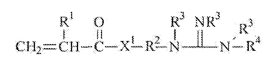
Summary of the Invention The present invention is directed to ligand functionalized substrates, preferably porous substrates, and methods of making the same. More specifically, the func tionalized substrates inc lude a base substrate, preferably a porous base substrate, which has been modified to provide grafted Ugand groups having the requisite affinity for binding neutral or negatively charged biomaterials, such as viruses. The ligand functionalized substrate may be described as the grafted reaction product of a substrate and a ligand monomer of Formula 1:
wherein
R1 is H or C,-C alkyl;
R is a divalent alkylcne, preferably having 1 to 20 carbon atoms and optionally containing an ester, amide, urethanc or urea linking group; each R3 is independently H oτ Cj-C alkyl;
R4 is H, C1-C alkyl or -N(R V and X1 is -O- or -NR*-. The base substrate may be directly- or indirectly grafted with the ligand monomer of Formula 1, as further described herein. Methods of making a ligand functionalized substrate are provided . In some embodiments, the method comprises: 1 ) providing a base substrate;
2) coating the base substrate with a solution comprising: (a) at least one grafting monomer having an acryloyl group and a photoinitiator group ("photoinitiator monomer"); (b) one or more ligand monomers of Formula 1, (c) optionally one or more monomers having at least one ac ryloyl group and at least one additional ethylenically unsaturated, free-radically polymerizable group; and (d) optionally one or more hydrophilic monomers;
3) exposing the coated base substrate to ionizing radiation, preferably e-beam or gamma radiation, to form a first functionalized substrate comprising grafted photoinitiator group attached to the surface of the base substrate, and
4) exposing the base substrate comprising grafted photoinitiator groups to UV radiation to polymerize the remaining ethylenically unsaturated, free-radically polymcrizablc groups. The term "ethylenically unsaturated group" refers to those groups having carbon-carbon double (or triple) bonds that may be frec-radicaHy polymerized, and includes (mcth)acrylamides, (meth)acrylates, vinyl and vinyloxy groups, allyl and allyloxy groups, and acetylenic group*.
Preferably the substrate is a porous substrate having interstitial and outer surfaces wherein the step of i h b omprises a first imbibing step with the photoinitiator m g radiation exposure to
produce a porous substrate having grafted photoinitiators thereon, followed by a second imbibing step with the ligand monomer, followed by UV polymerization to crosslink the remaining cthylenkally unsaturated, free-radically polymerizable groups. Optional monomers may be added with the first imbibing step prior to ionizing radiation exposure, or may be added in a second imbibing step.
In another embodiment, the step of imbibing may include a first imbibing step with the photoirύtiator monomer and the ligand monomer of Formula I, followed by ionizing radiation exposure, preferably e-beam or gamma radiation, to produce a porous substrate having grafted photoinitiator groups and grafted ligand groups, followed by UV polymerization to crosslink the remaining ethylcntcally unsaturated, free-radically polymerizable groups.
An artic le is provided comprising a porous substrate having interstitial and outer surfaces and grafted ligand groups extending from the surfaces thereof, said ligand groups of Formula II:
R1 is H or C1-C4 alky l;
R2 is a divalent alkylene, preferably having 1 to 20 carbon atoms and optionally containing an ester, amide, urethane or urea linking group; each R3 is independently H or C1 -C4 alkyl,
R4 is H, C1-C* atkyl or -N(R5^; and
X1 b -O- or -NR3-.
With respect to the above Formula Tf, the "-** represents a covalent bond or an organic linking group interposed between the ligand group and the surface of the base substrate. The article may further comprise grafted poly(oxyalkylcnc ) groups extending from the surfaces of the substrate, and may comprise grafted ethylenically unsaturated polymerizable groups extending from the surface of the substrate, which is preferably porous.
The article may comprise the further reaction product, upon grafting by exposure to ionizing radiatio ( f bl b ma radiation) and UV irradiation, of (c) monomers group and at least one
additional ethylenically unsaturated, free-radically polymerizable group and optionally d) monomers having at least one ethyleaically unsaturated, free-radically polymerizable group and a hydrophilic group. Any free cthylenically unsaturated groups that remain ungraded to the base substrate after e-beam exposure may polymeria upon subsequent exposure to UV radiation and therefore indirectly grafted to the base substrate.
With respec t to the method and artic le, all or a portion of the acryioyl groups of the photoinitiaior monomer a) will be grafted to the surface of the base substrate upon ionizing irradiation. The unreactcd photoinitiator monomers may be subsequently incorporated into the growing polymer chain on exposure to UV radiation. The remaining b), c) and d) monomers may be directly grafted to the surfaces (for example by grafting of an acryioyl group), or indirectly grafted by incorporation into the growing polymer chain on exposure to UV radiation.
These and other features and advantages of the present invention wilt become apparent after a review of the following detailed description of the disc losed embodiments and the appended claims.
Brief Detriotion of the Drawings
FIG. 1 depicts exemplary method steps for making hgand-functionalizcd porous articles of the present invention.
Defiled Desertofton of the Iiiventkm
In the article and methods of this invention, ligand-functionalized articles are provided by a two-step process of grafting of monomers (such as by e-bcam grafting) and subsequent UV crosslinking of free, ungraded ethylenically unsaturated polymerizable groupβ. Compared to the porous base substrate before surface modification, the ligand functional ized substrate typically has enhanced affinity for neutral or negatively charged biological materials such as host cell proteins, DNA, RNA and viruses. The affinity for such biomatcrials allows positively charged materials, such as antibodies to be purified, as they are not bound to the ligand functional groups. The ligand functionalized substrate allows the selective capture or
binding of target biomaterials by the ligand groups, while other materials, lacking the affinity for the ligand groups arc passed.
The ligand functional ized substrate comprises a number of components including, but not limited to, (1) a base substrate and (2) the UV initiated reaction product of a) a grafted photoinrtiator group extending from the surfaces of the base substrate, with (b) one or more ligand monomers of Formula II, c ) optionally one or mote monomers having at least one acryloyl group and at least one additional free- radically polymcrizable group and (d) optionally one or more hydrophilic monomers. Preferably the base substrate is a porous base substrate having interstitial and outer surfaces. As used herein, the term "acryloyl" refers to acrylate and acrylamide groups, and the term "(mcth)acryloyπ refers to acryloyl and methacryloyl groups
The base substrate may be formed from any suitable thermoplastic polymeric material. Suitable polymeric materials include, but ore not limited to, polyoletϊns, poly(isoprenes), poly(butadienes), Ωuorinated polymers, chlorinated polymers, polyamides, polyimides, polyethers, poly(ether sulfones), poly(sulfones), polyvinyl acetates), copolymers of vinyl acetate, such as poly(ethylene) -co-poly( vinyl alcohol),, pory(phosphazenes), poly(vinyl esters), polyvinyl ethers), poly( vinyl alcohols), and polycarbonates).
Suitable polyolefms include, but arc not limited to, polyethylene), pory(propylenc), pory(l -butene), copolymers of ethylene and propylene, alpha olefin copolymers (such as copolymers of ethylene or propylene with I -butcnc, 1 -hexene, 1 - octene, and 1-decene), poly(ethylene-co-l -butene) and poly(cmylene-cα-l -butene-co- 1 -hexene).
Suitable Ωuorinatcd polymers include, but arc not limited to, poly(vinyl fluoride), poly(vinylidene fluoride), copolymers of vinyl idene fluoride (suc h as poly(vinylidene fluoride-cø-bcxafhioropropy lene), and copolymers of chlorotrifluoroethylene (such as poly(ethylene-co-c hlorotrifluoroethylene).
Suitable polyamides include , but are not limited to, poly(iminoadipoyliminohexamethylcne), poly(iminoadipoyliminodecamethylene), and polycaprolactam. Suitable polyimides include, but are not limited to> poly(pyromcllitimide).
Suitable poly(cther sulfones) include, but are not limited to, pory(diphenylctbcτ sulfone) and poly<diphenyl3ul fone-cø-diphenylene oxide sulfonc ).
Suitable copolymers of vinyl acetate include, but are not limited to, pory(ethylene-co-vinyl acetate) and such copolymers in which at least some of the acetate groups have been hydrolyzed to afford various polyviny l alcohols).
The base substrate may be in any foτm such as films or sheets. Preferably the base substrate is porous. Suitable porous base substrates inc lude, but are not limited to, porous membranes, porous nonwovcn webs, and porous fibers.
In some embodiments, the porous base substrate is formed from a propylene homo- or copolymers, most preferably propylene homopolymcre. Polypropylene polymers are often a material of choice for porous articles, such as nonwovens and micropofous films, due to properties such as non-toxicity, inertness, low cost, and the case with which it can be extruded, molded, and formed into articles. However, polypropylene is hydrophobic. While it b desirable to render polymers suc h as polypropylene ligand functionalized, polypropylene treated with ionizing radiation is subjec t to degradation, e.g., embrittlement, discoloration, and thermal sensitivity , during or subsequent to irradiation, which therefore limits the ability to render such thermoplastic polymers ligand functionalized by e-beam grafting.
For radiation sensitive substrates, such as polypropylene, the present invention overcomes such polymer degradation by using a low dose of ionizing radiation preferably e-beam or gamma radiation, to graft photoinitiator groups and optionally grafting other monomers on a portion of the surface, then polymerizing or crosslmking any ungrafted, unreacted ethylenjcalh/ unsaturated groups by UV radiation. In many embodiments, the porous base substrate has an average pore size that is typically greater than about 0.2 micrometers in order to minimize size exclusion separations, minimize diffusion constraints and maximize surface area and separation based on binding of a target molecule. Generally, the pore size is in the range of 0.1 to 10 micrometers, preferably 0.5 to 3 micrometers and roost pre ferably 0.8 to 2 micrometers when used for binding of viruses. The efficiency of binding other targe t molecules may confer different optimal ranges.
Suitable porous base substrates include, but arc not limited to, porous and microporous membranes, nonwoven webs, and fibers. In some embodiments, the porous base substrate is a microporous membrane such as a thermally-induced phase separation (TIPS) membrane. TIPS membranes are often prepared by forming a homogenous solution of a thermoplastic material and a second material above the me lting point of the thermoplastic material. Upon cooling, the thermoplastic material crystallizes and phase separates from the 9econd material. The crystallized thermoplastic material is often stretched. The second material is optionally removed either before or after stretching. Microporous membrane are further disc losed in U.S. Patent Nos. 4,539,256 (Shipman), 4,726,989 (Mrozinski), 4,867,881 (Kinzer), 5, 120^94 (Mrozinski), 5,260,360 (Mrozinski et al.), and 5,962,544 (Waller), all of which are assigned to 3M Company (St. Paul, MN). Further, the microporous film can be prepared from ethylene-vinyl alcohol copolymers as desc ribed in U.S. Patent No. 5,962,544 (Waller). Some exemplary TIPS membrane comprise poly(vinylidene fluoride) (PVDF), pofyolefins such as polyethylene homo- or copolymers or polypropylene homo- or copolymers, vinyl-containing polymers or copolymers such as ethylene-vinyl alcohol copolymers and butadiene-c ontaining polymers or copolymers, and acrylate- containing polymers or copolymers. For some applications, a TIPS membrane comprising PVDF is particularly desirable. TIPS membranes comprising PVDF arc further described in U.S. 7,338,692 (Smith et al.).
In another exemplary embodiment the porous bases substrate comprises a nylon microporous film or sheet, such as those described in U.S. Patent Nos. 6,056,529 (Meyering et al.), 6,267,916 (Meyering ct al.), 6,413,070 (Meyering ct al.), 6,776,940 (Meyering et al.), 3,876,738 (Marinac chio et al.), 3,928,517, 4,707,265 (Knight ct al.), and 5,458,782 (Itou et al.).
In other embodiments, the porous base substrate is a nonwoven web which may include nonwoven webs manufactured by any of the commonly known processes for producing nonwoven webs. As used herein, the term "nonwoven web" refers 10 a fabric that has a structure of individual fibers or filaments which are randomly and/or unidirectionally interlaid in a mat-like fashion.
For example, the fibrous nonwoven web can be made by carded, air laid, spunlaccd, spunbonding or melt-blowing techniques or cotnbinations thereof. Spunbondcd fibers are typically smal l diameter fibers that are formed by extruding molten thermoplastic polymer as filaments from a plurality of fine, usually circ ular capillaries of a spinneret with the diameter of the extruded fibers being rapidly reduced. MeltWown fibers are typically formed by extruding the molten thermoplastic material through a plurality of fine, usually circular, die capillaries as molten threads or filaments into a high velocity, usually heated gas (e.g. air) stream which attenuates the filaments of molten thermoplastic material to reduce their diameter. Thereafter, the mcllblown fibers arc carried by the high velocity gas stream and are deposited on a collec ting surface to from a web of randomly disbursed meltblown fibers. Any of the non- woven webs may be made from a single type of fiber or two or more fibers that differ in the type of thermoplastic polymer and/or thickness.
Further details on the manufacturing method of non-woven webβ of this invention may be found in Wcntc, Superfine Thermoplastic Fibers, 48 INDUS. ENG. CHEM . 1342( 1956), or in Wente e< al., Manufacture Of Superfine Organic Fiber*, (Naval Research Laboratories Report No. 4364, 1954).
The functionaltzed substrate has grafted groups attached to the surfaces of the base substrate which includes a) at least one photoinitiator group (or the reaction product thereof), with (b) one or more ligand monomers, c) optionally one or more monomers having at least one acryloyl group and at least one additional free-radically polyrnerizable group and (d) optionally one or more hydrophllic monomers.
The monomers that are grafted to the surface of the base substrates usual ly have both (a) an acryloyl group for grafting by e-beam and b) at least one additional function group thereon, which includes a) a photoinitiator group to initiate the polymerization on exposure to UV radiation, b) a ligand group derived from monomers of Formula H, optionally c) a (methjacryloyl or a non-(m©th)βcryloyl, free- radically polymcrizablc ethylenic aily unsaturated group for subsequent polymerization derived from the "c)M monomers and optionally d) a hydrophilic group, inc luding ionic groups derived from the "d)" monomers.
Acryloyl groups, inc luding acrylate and acrylamide groups are preferred for direct grafting of the monom c to the greater reactivity of
such acry loyl groups on exposure to kmizing radiation, such as e-beam irradiation. However, not all such acryloyl groups may be "directly grafted", i.e. forming a covalent bond with the substrate surface. Some may remain free, and are subsequently "indirectly grafted" by incorporation into the polymer chain on exposure to UV radiation. Other ethylenically unsaturated groups, such as methβcry lamides, mcthacrylates, vinyl and vinyloxy groups, ally! and allyloxy groups, and acetylenic groups are less reactive during e-beam grafting, and are less likely to be directly grafted to the base substrate. Therefore a portion of such non-acryk»yl groups may be directly grafted, but large ly remain unreacted, and are indirectly grafted to the substrate by incorporation into the polymer chain during UV initiated polymerization. The phoioinitiatoT Ma)" monomers may be directly grafted onto surface of the base substrate, including the interstitial and outer surfaces of the porous base substrate to provide the requisite grafted photoinitiaior group via the acryloyl group. The ligand "b)" monomers (of Formula I) may have an acryloyl group for direc t grafting or a non-acryloyl group, such as a methacrylate group, for subsequent incorporation (indirect grafting) into the polymer chain during UV initiated polymerization. In addition to an acryloyl group, the free-radically polymerizablc groups of monomer "c )" are typically other ethylenically unsaturated groups such as a methacrylamides, methacryktes, vinyl groups and acetylenic groups having reduced reactivity during grafting, and are therefore free and unreacted for the subsequent UV initiated polymerization and crosslinking.
The acry loyl group of the "c)M monomers typically can directly graft (i.e. forming a covalent bond) to the surface of the base substrate when exposed to an ionizing radiation preferably e-beam or gamma radiation. Thai is, reaction of acryloyl groups of the c) monomers with the surface of the porous base substrate in the presence of the electron beam results in the reaction of ethylenically unsaturated free- radically polymerizablc groups directly grafted to the base substrate via the acrylate group.
A fourth grafting hydrophilic monomer **d)" may also be grafted via an ac ryloyl group, and may provide hydrophilic groups or ionic groups to the surfaces of the base substrate. In some embodiments, hydrophilic monomers having an ionic group may be directly or ind e surface to provide
secondary ionic interaction of the functional izcd substrate. For example, ionic groups may be selected to have a positive charge (at a selected pH) to retard or repeJ various biomaterials from the substrate surface. In other embodiments the fourth monomer may have an ethytenteally unsaturated group of reduced reactivity during the grafting step, but is subsequently incorporated by free-radical polymerization during the UV curing step (indirectly grafted).
The grafting photoinitiator monomers include an acryloyl group and a photoinitiator group, which may be a hydrogen-abstracting type or an α-cleavage-type photomitiator group, and may be represented by the formula:
X1 is -O or -NR3, R3 is independently H or C)-C4 alkyl;
R6 is a divalent linking group connecting the acrylatc group with the PI group; and PI is a photoinitiator represented by the structure:
.7 , wherein R is H or a C1 to C4 alkyl group, each R9 is independently a hydroxyl group, a phenyl group, a Cj to C^ alkyl group, or a C) to C0 alkoxy group. Such photoinitiator monomers are described, for example, in U.S. Patent Nos. 5,902.836 (Babu et al.) and 5,506,279 (Babu et al.). Further
details regarding the linking R6 group may be found with reference to the method of preparing the photoinitϋoor grafting monomer herein, and in the cited references.
In certain preferred embodiments, the photoinitiator monomers may be of the hydrogen-abstraction type represented by the general formula;
X1 is O or NH; p is Oor 1 ; o is 0 or an integer from 1 to 5; a, b, and c are independently 0 or 1 ; M1 is CH2 or Si(R1 b ; MMs CXR'h or SKR'h; M3 is -O-, -NH-, -C(O)-, -C(O)O-, -C(O)NH-, or -OC(O)NH-; Each R1 is independently H or a C1 to C« alky I group;
G is a covalent bond, -(CHjXr-, or -<CH2)d O- where d is an integer from 1 to 4, preferably from I to 2;
PI1 is a radiation-sensitive hydrogen abstracting group having the general formula:
in which Ar is a substituted arene having 6 to 12 carbon atoms, preferably a bcnzcnetriyl group,
R12 is hydrogen, a C1 to Cn alkyl group, a C1 to Cu alkoxy group, or a phenyl group; and
R° is a C1 to C* alkyl group, a cycloalkyl group having 3 to 14 carbon atoms, or
wherein R
14 and R
15 arc independently selected from hydrogen, Cj to Cn alkyl groups, C| to C 12 alkoxy groups, and phenyl groups.
Inc luded among those hydrogen abstracting photoinitialor monomers encompassed by Formula XIIl are those where PI1 is a moiety derived from one of the following compounds (or a substituted derivative thereof), the bond to G is preferably located para to the bridging carbσnyl group: benzøpheneone, anthraquinone, 5, 12-naphthaccnequinonc . aceanthracenequinone, benz(A)anthraceiie-7,12-diorje, 1 ,4-chrysenequinone, 6,13- penlacenequinone, 5,7, 12,14-pentacenetetrone, 9-fluorenone, enthrone, xanthonc , thioxanthone, acridone, dibenzosuberone, ac etophenone, and chromone. The synthesis of the formula XlIl monomers is described in U.S. 5,773,485 (Bennett et al).
The weight percentage of the photoinitiator monomers of Formula XIl or XlII in the imbibing solutions) may be at least about 0.15%, and generally less than about 10%, relative to the total weight of other monomers (i.e. ub)n, uc )*\ and "d)M monomers). It will be understood that all or a portion of the photoinitiator monomers may be directly grafted to the surfaces of the base substrate upon exposure to e-beam irradiation. Those unreacted , ungrafted photoinitiator monomers will be incorporated into the growing polymer chain on exposure to UV radiation, thereby indirectly grafting the monomers to the porous base substrate. It will be further understood where multiple imbibing steps are used, one of more of the imbibing solutions may contain no photoinitiator monomers.
A variety of photoinitiator grafting monomers can be made by reaction of: I ) an acryloyl monomer comprising a first reactive functional group with 2) a compound that comprises a radiation-sensitive group (photoinitiator group) and second reactive functional group, the two functional groups being co-reac tive with each other. Preferred co-reactive compounds are cthylcnicaUy unsaturated aliphatic, cycloaliphalic, and aromatic compounds having up to 36 carbon atoms, optionally one or more oxygen and/or nitrogen atoms, and at least one reac tive functional group. When the first and second functional groups react, they form a covalent bond and link the co-reac tive compounds. Examples of useful reac tive functional groups inc lude hydroxyl, amino, oxazolinyl, oxazolonyt. acetyl, acetonyl, carboxyl, isocyanato, epoxy, aziridinyl, acyl halide, and cyclic anhydride ve functional group is an
isocyanato functional group, the second, co-reactivc functional group preferably comprises a amino, carboxy l, or hydroxyl group. Where first reactive functional group comprises a hydroxyl group, the second, co-reactive functional group preferably comprises a carboxyl, isocyanato, epoxy, anhydride, ac yl halide, or oxazolinyl group. Where the first reactive functional group comprises a carboxyl group, the second co- reactive functional group preferably comprises a hydroxyl, amino, epoxy, vinyloxy, or oxazolinyl group.
Representative examples of aery late compounds having a reactive functional group include hydroxy alky I acrylatcs such as 2-hydroxyetbyl aery I ate and 2-(2- hydroxyethoxy)ethyl aery late; aminoalkyl acxylates such as 3-aminopropyl acrylate; oxazokmyl compounds such as 2-ethcnyH,3-oxa2oHn-5-onc and 2-pτopcnyI-4,4- dimcthyl-l ^-oxazolin-S-one; carboxy 'Substituted compounds such as acry lic acid and 4-carboxybenzyi acrylate; isocyanato-substitutod compounds such as isocyanatoethyl acrylate and 4-isocyanatocyclohcxyl acrylate; epoxy-βubsdtutcd compounds such as glycidyl acrylate; aziridinyl-subβtrtuted compounds such as N-acryloylaaridine; and acryloyl halides.
Representative examples of co-reactive compounds inc lude functional group- substituted compounds such as l -H-hydroxypbcayl^^-dirnethoxyethanonc, l -{4~<2- hydroxyethyl)ρhenyl]-2^-dunethoxyethanone, (^isøcyanatopbenylKW-dimethoxy- 2-phenylcthanone, ! -{4-f2-{2,3-epoxypropoxy)pheτiyl]}-2,2-dimethyl-2- hydroxycthanone, l -(4<2-βrmnocthoxy)phenylJ-2^κlirrκrtrκ>xy«thanoτ»e, and l -[4- (carbon^thoxy)phenyl]-2>2-^methoxyethanone.
It will be understood that all or a portion of the acrylate groups of the phoioinitiator monomer may be directly grafted to the surface of the base substrate on irradiation. Those ungraftcd, free acryloyl groups may be subsequently indirectly grafted to the substrate by incorporation into the polymer chain on UV initiated polymerization.
The second grafting **b)" Iigand monomers comprise an acryloyl group and a ligand group having affinity for neutral or negatively charged biological materials. The ligand monomers are of the general formula previously described:
R1 is H or C1-C4 alkyl;
R2 is a divalent alkylenc, preferably having 1 to 20 carbon atoms and optionally containing an ester, amide, ure thane or urea linking group; each R3 is independently H or C1-C4 alkyl;
R4 is H, C1-C4 alky) or -N(R3)2; and X1 is -O- or -NR3-.
Such ligand monomer may be made by condensation of an (mcth)ac ryloyl compound, typically a (meth)ac ry loyl halkte with a compound of the formula:
where X
1, and R
2 to R
4 arc as previously defined.
Jn certain preferred embodiments, the ligand monomers are of the general formula:
where R
1 is H or C
1-C
4 alky I, eac h R
3 is independently H or C
1-C
4 alkyl,
R4 is H, C1-C4 alkyl or -N(R3)2,
X1 is -O- or -NR3-, where R3 is H or C1-C4 alkyl,
R7 and R1 are each independently C1 to C10 alkylene; and Z is an ester, amide, urea, or urethane group. Preferably the sum of carbon atoms in
R7 and R1 is 2 to 10.
In a manner similar to that desc ribed for the photoinitiator monomers of
Formula XII, the ligand monomers of Formula Ia can be made by reaction of: 1 ) an acryloyl monomer comprising a first reactive functional group with 2) a compound that comprises a ligand group and second reactive functional group (such as those of
Formula IV), the two functional groups being co-reactive with each other. When the first and second functional groups react, they form a covaleπt bond and link the co- reactive compounds by the indicated "Z" group. In gome embodiments, ligand
monomers of Fortnul* Ia may be prepared by the reaction of an alkenyl oxazolinone with a compound of Formula IV. h will be understood that ail or a portion of the acryloyl groups of the ligand monomer I or Ia may be directly grafted to the suτface(») of the substrate on exposure of ionizing radiation if incorporated into the first imbibing step, or may be subsequently indirectly grafted to the substrate by incorporation into the polymer chain on UV initiated polymerization.
If directly grafted, the surface(s) of the base substrate may comprise ligand groups attached thereto of the formula:
where X\ and R
1 to K
4 are as previously defined.
If indirectly grafted, the ligand monomer will be grafted via the residue of the photoinitator and the base substrate will have ligand groups attached thereto of the formula:
R1, R2, R3, R4, RJ and X1 as previously defined; and
PI* is the residue of a photoinitiator grafted to the substrate surface . For example a grafting photoinitator monomer such as 2-propenoylaminoethaftoic acid; 2-(4-(2- hydroxy-2 methylpropanoyl)phenoxy)ethyl ester may be grafted to a substrate surface using ionizing radiation such as e-beam energy. In the presence of LTV, the photoinitiator undergoes alpha cleavage to two radicals. In the presence of the ligand monomer, or other monomers, the radical may add to the ethylenicaUy unsaturated group (such as the depicted acryloyl group) to indirectly graft the ligand monomer to the substrate surface via the residue of the photoinitator as shown in formula VI and illustrated in Scheme I below. It will be further understood that the radical addition product of the ligand monomer may further copolymerize with additional ligand monomers and the other optional monomers to produce a grafted polymer having ligand groups pendent therefrom.
Scheme I
It will be further understood that the grafting process will yield a radical spec ies, having a radical on the carbon alpha to the carbonyl of the ligand monomer or Formula I, that may further polymerize wiih one of more additional ligand "b)" monomers, one of more photoinitiator **a)" monomers, one or more "c)" monomers βnd/or one of more **d)" monomers, resulting in a grafted polymers having these groups pendent from the polymer chain as simply illustrated below. The formation of grafted polymer chains significantly increases the density of the desired ligand groupβ, and the efficiency of binding. Substrate^MΥCM^^ M^M^^
In the formula, the -(M^1)- represent the residue of the grafted photoinitiator monomer (aβ illustrated in Scheme I. the (Mb), represents the polymerized ligand monomer, having "x* polymerized monomer units, where x is at least one and preferably at least two, -{M^ p h l i d monomer *c)'\ having y polymerized monomer units preferably at least 1 and -
(M^ represents the polymerized monomer ud)w having z polymerized monomer units, where z may be zero and is preferably at least 1. The polymer may be random or block, and the "c)" monomer, having two polymerizable groups may provide a crosslink bet ween polymer chains. The polymer may be directly grafted via the residue of the photoinitiator, as shown in Scheme I, or may be directly grafted via the ligand Mb)H monomers as shown in Formula V, the "c)" monomers or the "d)" monomers, as described herein. The polymer may further comprise polymerized photoinitiator monomer units from unreacted, ungraded photoinitiator monomers.
The third grafting **c )" monomers comprises (a) one or more acryloyl groups for grafting and (b) one or more second, cthylenicaUy unsaturated, free -radically polymerizable groups for subsequent crossl inking. The second cthylenically unsaturated group may be an aery late or a non-acrylatc; i.e. other cthylenically unsaturated groups having reduced reactivity relat ive to the acrylate group during the e-beam grafting step. Preferably the second ethytenically unsaturated group is a non- acrylate group and is left largely free and unreacted during the grafting step for subsequent UV crot slinking. Use ful second, non-acrylate ethy tenically unsaturated groups include methacrylates, (meth)acrylamides, vinyl groups, vinyloxy, acety lenic groups, allyl and allyloxy groups.
Useful third grafting monomers "c)M may have the generalized structure: [CH2=CH-C<0>-XVR10-Q-Z*, VIl where Z is an acryloyl or non-acryloyl, cthylenically unsaturated polymerizabte group,
X1 is -O- or -NR3, where RJ is H or C1-C* alkyl,
Q is a divalent linking group selected from a covalent bond "-**, -O-, -NR1- , -COj- and
-CONR1-. where R1 is H or C1-C4 alkyl; and
R10 is an aikylene group of valence a+b, preferably having 1 to 20 carbon atoms and optionally containing one or more catenary oxygen atoms and/or one or more hydroxy! groups; and a and b are each at least one. Preferably the Z group is a non- acryloyl of reduced reactivity that is indirectly grafted into the polymer chain during UV initiated polymerization.
In certain embodiments, R10 is a poly(alkylene oxide group) to provide hydrophilicity to the ftmctionalized substrate, and is of the formula: Z-Q-(CH(R1KlVO)0-C(O)-CH-CH2, VIII wherein Z is an acryloyl or non-acry loyl, polymerizable ethylenically unsaturated group,
R1 is a H or a C1 to C* alkyl group, and n is from 2 to 100, preferably 5 to 20, and Q is a divalent linking group selected from a covalent bond **-", -O-, -NR1- , -COj- and -CONR1-, where R1 is H or C1-C4 alkyl. Preferably the Z group is a non-ac rylate of reduced reactivity that is indirectly grafted into the polymer chain during UV initiated polymerization.
In one embodiment, the poly(alkylcnc oxide) group (depicted as -(CH(R1)- CHjO^r) is a poty(cthyicnc oxide) (co)polymer. In another embodiment, the poly(alkylcne oxide) group b a poly(ethylcne oxide-co-propylene oxide) copolymer. Such copolymers may be block copolymers, random copolymers, or gradient copolymers.
Suitable monomers having a first acryloyl group for grafting and a second ethylenically unsaturated group for subsequent UV polymerization include, but are not limited to, polyalkylene glycol acrylate mcthacrylate including those derived from polyethylene glycol and polypropylene glycol ac rylated monomers. In another embodiment, the third "c)" monomer is a partially acrylated polyol, having at least one acrylate groups and at least one other ethylenically unsaturated polymerizable group, which is preferably not a acry late group and may be selected from methacrylates, (rneth)acrylamides, vinyl groups, vinyloxy, acetylenic groups, aJlyl and allyloxy groups. Such partially acrylated polyols may have one or more free hydroxy! groups.
Polyols useful in the present invention inc lude aliphatic, cycloaliphatic , or alkanol-subβthuted arene polyois, or mixtures thereof having from about 2 to about 18 carbon atoms and two to five, preferably two to four hydroxyl groups.
Examples of useful polyols inc lude 1 ,2-ethanediol, 1 ,2 -propanediol, 1 ,3- propanediol, 1.4-butanediol, 13-butanediol, 2-methyl-l ,3-propanedk>l, 2,2-dimethyl- 1,3-propancdiol, 2-ethyl-l ,6-hcxanediol, 1 ,5-pcntanediol, 1,6-hexanediol, 1 ,8- ocianediol. neopcntyl glyco e, 1,2,6-hexanetriol,
trimethylolethanc, pcntacrythritol, quinitol, maπmtol, sorbitol, dicthlcnc glycol, methylene glycol, tetraethyleπe glycol, 2-ethyl-2-(hydroxyτr»ethyl)-l ,3-propancdiol, 2-ethyl-l ,3-pcnUnediol, 1 ,4-cyclohexanedimethanol, 1,4-berizenedirnethanol, and polyalkoxylatcd bisphenol A derivatives. Most preferably "c)" monomers are those monoacrylates of glycerol having a free hydroxyl group and a methacry late group suc h as 3-{acryloxy>-2-hydroxyprOpylmcthacrylate).
In some preferred embodiments, the ethylenically unsaturated, free -radically polymcrizable groups of the ligand Mb)" and ethylenically unsaturated "c)" monomers and hydrophilic "d)" monomers are chosen to be efficiently copolymerizable with each other. That is, it is preferred that eac h of the ^b)", "c)" and "d)M monomers have the same polymcrizable groups.
In one exemplary embodiment, the grafted species results from the reaction of a polyethylene glycol acrylate monomer of Formulas VH or VFIl with the base substrate upon exposure to an ionizing radiation preferably e-beam or gamma radiation. These grafting monomers can be used to change a hydrophobic porous base substrate into a hydrophilic functionali2ed substrate due to the presence of the poly(alkylene oxide) group. The resulting hydrophilic substrate can have a number of desired properties such as instant wettability. For some hydrophobic substrates such as those prepared from polytvinyiidene fluoride) (PVDF) it is preferred to imbibe and graft first with a hydrophilic "<:)** monomer of Formulas VIl or Vl 11 prior to imbibing and grafting with the photoinitiator a) monomer end ligand b) monomer to render the substrate hydrophilic prior to ligand functionalization.
The optional fourth hydrophilic monomer "d)M, comprises at least one acryloyl or other non-acryloyl group of reduced reactivity, and a hydrophilic group, inc luding poly(oxyalkylene) and ionic groups, for providing hydrophilicity to the substrate, or for providing greater selectivity to the substrate when binding viruses. If the optional fourth monomer contains an acryloyl group, it may be directly grafted to the surfaces) of the base substrate. If it contains a non~*cryloyl, cthylenicaliy unsaturated group it may remain largely unreacted during the grafting step, and will be incorporated during the UV po lymerization step. It will be understood that al l or a portion of the acryloyl groups may be direc tly grafted to the porous substrate, and a portion may be unreacted, b to the polymer upon UV
initiated irradiation. Conversely, a portion of other ethyienically unsaturated groups of reduced reactivity may be directly grafted, but such groups generally remain largely unreacted during the grafting step and are indirec tly grafted into the polymer upon UV initiated irradiation. The hydropbilic ionic groups may be neutral, have a positive charge, a negative charge, or a combination thereof. With some suitable ionic monomers, the ionic group can be neutral or charged depending on the pH conditions. This class of monomers is typically used to impart a desired hydrophilicity to the porous base substrate in addition to the c) monomer. In applications for viral capture, the addition of a grafting ionic monomer having a positive charge at the selected pH may allow selective binding of viruses while repelling positively charged biological materials such as antibodies.
In some preferred embodiments, the third monomer may have an acrylatc group, or other cthylenically unsaturated groups of reduced reac tivity, and a poly(alkylene oxide) group; e.g. roonoacrylated poly(alkylcne oxide compounds, where the terminus is a hydroxy group, or an alkyl ether group.
In some embodiments the ionic monomers having a negative charge include (mcth)acryloylsulfonic acids of Formula IX or salts thereof.
wherein, Y is a straight or branched alkylcnc (e.g., an alkykncs having 1 to 10 carbon atoms, 1 to 6 carbon atoms, or 1 to 4 carbon atoms) and L is -O- or -NR
3-, where R
3 is H or C
1-C4 alkyl-;. Exemplary ionic monomers according to Formula IX include, but are not limited to, N-acrylamidomethanesulfonic acid, 2- acrylamidoethanesulfonic acid, 2-acrylamido-2-methyl-I-propanesulfonic ac id, and 2- meύSacryiainido-2-methy 1-1 -propanesulfoαic acid. Salts of these acidic monomers can also be used. Counter ions for the salts can be, for example, ammonium ions, potassium ions, lithium ions, or sodium ions. It will be understood with respect to Formula IX that the grafting acryloyl group may be replaced by another cthylenically unsaturated group of reduced reactivity for subsequent incorporation (indirec t grafting) during UV initiated polymerizatioα
Other suitable ionic grafting monomers having a negative charge (at a selected pH) include sulfonic acids such as vinylsulfonic acid and 4-styrenesulfonic acid; (meth)acrylamidophosphoτuc acids such as (meth)acrylamidoalkylpnosphonic acids (e.g., 2-(meth)acrylamidoethylphosphomc acid and 3- (meth)acrylamidopropylphosphonic acid; acrylic acid and methacrylic acid; and carboxyalkyl(meth)acrylale8 such as 2-carboxyethyl(meth)acrylate, and 3- carboxyρropyl(meth)acrylate. Still other suitable acidic monomers include (meth)acryloylamino acids, suc h as those described in U.S. Patent No. 4,157,418 (Hcilmann). Exemplary (mcth)βcryloylamino acids inc lude, but are not limited to, N- acryloylglyc ine, N-acryloylaspβrtic acid, N-acryloyl-β-βlanine, and 2- acrylamidoglycolic acid. Salts of any of these acidic monomers can also be used. Some exemplary ionic grafting monomers that are capable of providing a positive charge (at a selected pH) are amino (mcth)aαrylates or amino (meth)acrylamjdcs of Formula X or quaternary ammonium salts thereof. The couπterions of the quaternary ammonium salts arc often halides, sulfates, phosphates, nitrates, and the like.

where L is -O- or -NR
3-, wheTe R
3 is H or C
1-C
4 alkyl-; and Y is an alkylenc (e.g., an alkylenc having 1 to 10 carbon atoms, 1 to 6, or 1 to 4 carbon atoms). Bach R" is independent ly hydrogen, alkyl, hydroxyalkyl (i.e., an βlkyl substituted with a hydroxy), or aminoalkyl (i.e., an alkyl substituted with an amino). Alternatively, the two R
1 ' groups taken together with the nitrogen atom to which they are attached can form a heterocyclic group that is aromatic, partially unsaturated (i.e., unsaturated but not aromatic), or saturated, wherein the heterocyclic group can optionally be fused to a second ring that is aromatic (e.g., benzene), partially unsaturated (e.g., cycloheκene), or saturated (e.g., cyclohexane).
It will be understood with respect to Formula* IX and X that the grafting acryloyl group may be replaced by another ethylenically unsaturated group of reduced reactivity, suc h as methacrylatc, methacryUmide, vinyl, vinyloxy, ally, alloxy, and acetylcnyl for subsequent in i (i di fti ) during UV initiated polymerization.
In some embodiments of Formula X, both R11 groups are hydrogen. In other embodiments, one R" group b hydrogen and the other is an alkyl having 1 to 10, 1 to 6, or 1 to 4 carbon atoms. In still other embodiments, at least one of R1' groups is a hydroxy alkyl or an amino alkyl that have 1 to 10, 1 to 6, or 1 to 4 carbon atoms with the hydroxy or amino group being positioned on any of the carbon atoms of the alkyl group. In yet other embodiments, the Ru groups combine with the nitrogen atom to which they are attached to form a heterocyclic group. The heterocyclic group includes at least one nitrogen atom and can contain other beteroatoms such as oxygen or sulfur.
Exemplary heterocyclic groups include, but are not limited to imidazolyl. The heterocyclic group can be fused to an additional ring such as a benzene, cyclohcxenc , or cyclohcxane . Exemplary heterocyclic groups fused to an additional ring include, but arc not limited to, benzo imidazolyl.
Exemplary amino acrylateβ (i.e., L in Formula X is -O-) inc lude N,N- dialkylaminoalkyl acryUtcs such as, for example, K.N-dimethylaminoethyl aery late, N^-dimethylaminoethylacrylate, N,N-dicthyiaminoethy l acyiate, N,N- dxethy laminoe thy lacry late, N,N-dimelhylaminoprσpylac rylate, N,N- dimemylaminopropylacrylate, N-tert-butylaminopropylmcthacrytete, N-tert- butylaminopropytacrylate and the like.
Exemplary amino (mcth)acrylamides, (i.e., L in Formula X is -NR3-) inc lude, for example, N-<3-<«nmopropyl)fncthacrylarnide, N-(3-aminopxopyl)acry lamidβ, N- [3Kdimethylamino)propyl]rnctbβcrylamide, N-(3-imidazolylpropyl )metbacry lamide, N-(3-imidazolylpropyl)acry laraide, N-(2-imklazolylethyl)methacry lamidc , N-( l ,l - dimethyl-3-imidazoylpropyl)mcthacrylamidc, N-(Ll -dimcthyl-3- imidazoylpropyi)acrylamidc, N-(3-benzoimJdazolylproρyl)acτylamide, and N-(3- bcnzoimidazolylpropyOmethacrylamide.
Exemplary quaternary salts of the ionic monomers of Formula X inc lude, but are not limited to, (m«h)acιylamidoalkylunmewylarnroonium salts (e.g., 3- lnethacj^lamidopropy ltrimethylarnmonium ch loride and 3- acryiamidopropyttrimethylammonium chloride) and (meth)βcryloxyalkyhrime(hylammonium salts (e.g., 2- acryloxycthy ltrimcthylarrunonium chloride, 2-rnethacryloxyethyltrirnelhylamrnoniurn chloride, 3-rnethacr>1oxy-2- onium chloride, 3-acryloxy-
2-rrydroxyjjtopyltrimethylanτnκmium chloride, and 2- acryloxycthyltrimcthylammonium racthyl sulfate).
Other monomers thai can provide positively charged groups (at a selected pH) to the base substrate include the dialky laminoalkylamine adducts of aikenylazlactones (e.g., 2-(diethylamirκ>)ethylamiΛe, (2-aminocthyl)trirn€thyiammonium chloride, and
3-{dimcthylamino)propylamine adducl5 of vinyldimethylazJactonc) and diallylamine monomers (e.g., diallylammonium chloride and diallyldimethylammonium chloride).
Others inc lude the alkenylazlactones adducts of polyetheramincs (such as the monoamine, diamine and triamines based on the potyctheramine structure). One example ofthese compounds is the JeffarnineΦ series, from Huntsman, The
Woodlands, TX, USA. Other examples include the quaternary salt of dimcthylaminocthyl methacrylate.
A fourth, neutral d) monomer, that may be incorporated by direct grafting or during subsequent UV polymerization (indirect grafting) are poly(alkyfcnc oxide) monomers having a (meth)acry!oyl or non-acryloyl cthyknically unsaturated group and a non-polymerizable terminus. Such monomers may be of the formula:
CH2=CR'-C(O)-XI-(α4(Rl)-CH2-O)n-R', Xl wherein each R1 is independently H or C1-dalkyl, X1 is -O- or -NR3-, where R3 is H or C1-C4 alkyl. As described in further detail below, funcu'onalized substrates may be prepared using above-described d) monomers to provide hydrophilicity or ionic character to the surface of a base substrate. When two or more of the above-described monomers are used to alter the surface properties of a base substrate, the monomers may be grafted onto the base substrate in a single reaction step (i.e., the two or more grafting monomers are all present upon exposure to ionizing radiation) or in sequential reaction steps (Le., a first grafting photoinitiator monomer "a)", is present upon a first exposure to ionizing radiation and α second grafting monomer **b) and/or c)" is present upon a second exposure to the ionizing radiation). Similarly, all of such monomers a), b), c) and d) may be present during a first grafting 9tep and directly grafted, or indirectly grafted by incorporation during the subsequent UV initiated polymerization. Alternatively, all or a portion of such monomers may be imbibed in a first step, or in subsequent im hydrophobic substrates may
be rendered hydrophiltc by first imbibing and grafting with β hydrophilic monomer, such as represented by Formulas VII] or XI, and tb«n subsequently imbibing and directly grafting with the photoinitiator a) monomers, and imbibing and directly or indirectly grafting with the other b), c) and d) monomers. The above-described ligand functional ized substrates may be prepared using a combination of process steps. The method comprises:
1) providing a base substrate, preferably a porous base substrate having interstitial and outer surfaces;
2) coating the base substrate (preferably imbibing the porous substrate) with a solution comprising (a) at least one grafting monomer having an acryloyl group and a photoinitiator group of Formula XIl; (b) one or more ligand b) monomers of Formulas I or Ia, (c) optionally one or more c) monomers having at least one ac ryloy l group and at least one additional cthylenically unsaturated, free-radically polymcrizable group of Formulas VII or VIII; and (d) opt ionally one or more hydrophilic d) monomers of Formulas IX, X or XI;
3) exposing the coated substrate (or imbibed porous base substrate) to ionizing radiation so as to form a first func tionalized substrate comprising grafted photomitiator group attached to the surfaces) of the base substrate, and
4) exposing the base substrate comprising grafted photoinitiator groups to UV radiation to polymerize the remaining ethylenically unsaturated, free-radically polymcrizable groups.
In a particularly preferred embodiment, the method comprises: 1 ) providing a base substrate, preferably a porous base substrate having interstitial and outer surfaces;
2) coating the base substrate (preferably imbibing the porous substrate) with a first solution comprising (a) at least one grafting monomer having an acryloyl group and a pbotoinitiator group of Formula XII; (b) optionally one or more ligand monomers of Formulas I or Ia, (c) optionally one or more monomers having at least one acryloyl group and at least one additional ethylenical ly unsaturated, free-radically polymerizable group of Formulas VH or VIII; and (d) optionally one or more hydrophilic monomers of Fo
3) exposing the coated substrate (or imbibed porous base substrate) to ionizing radiation, preferably e-b©βm or gamma radiation, so as to form a first functional ized substrate comprising a base substrate having grafted pbotoirύtiator group attached to the surfacets) thereof; 4) coating the base substrate (preferably imbibing the porous substrate) having grafted photoinitiator groups with a second solution comprising (b) one or more of said Hgand monomers, (c) optionally one or more monomers having at least one acryloyl group and at least one additional ethylcnically unsaturated, free-radic ally polymcrizable group; and (d) optionally one or more hydrophilic monomers; 5) exposing the base substrate comprising grafted photoinitiator groups to UV radiation to polymerize the remaining ethylcnical ly unsaturated, free-radically poly men zabJc groups.
The methods of the present disc losure involve the irradiation of porous or non- porous substrate surfaces with ionizing radiation to prepare free radical reaction sites on such surfaces upon which the monomers are grafted. "Ionizing radiation" means radiation of a sufficient doββge and energy to cause the formation of free radical reaction sites on the surface^) of the base substrate. Ionizing radiation may inc lude beta, gamma, electron- beam, x-ray and other electromagnetic radiation. In some instances, corona radiation can be sufficiently high energy radiation. The radiation is sufficiently high energy, that when absorbed by the surfaces of the base substrate, sufficient energy is transferred to that support to result in the cleavage of chemical bonds in that support and the resultant formation of a free radical site on the support.
High energy radiation dosages are measured in megarads (Mrad) or kilograys (kθy), whic h is 1/10 of a mRαd. Doses can be administered in a single dose of the desired level or in multiple doses which accumulate to the desired level. Dosages can range cumulatively from about 1 kGys to about 100 kGys. Preferably, the cumulative dosage exceeds 30 kGys (3 Mrads) for substrate resistant to radiation damage.
Electron beam and gamma radiation are preferred for this method of grafting due to the ready-availability of commercial sources. Elec tron beam generators are commercially available from a variety of sources, including the ESI "ELECTROCURE" EB SYSTEM from Energy Sciences, Inc. (Wilmington, MA), and the BROADBEAM EB PRO red Systems, LLC
(Davenport IA). Sources of gamma irradiation are commercially available from MDS Nordion using a cobalt-60 high-energy source . For any given piece of equipment and irradiation sample location, the dosage de livered can be measured in accordance with ASTM E-1275 entitled "Practice for Use of a Radiochromic Film Dosimetry System/ By altering extractor grid voltage, beam diameter and/or distance to the source, various dose rates can be obtained.
The base substrate may be nonporous or porous. Some of the porous base substrates used in this embodiment can be porous, microporous, nonwoven, or a combination thereof. One exemplary method for making ftmctionalized substrates is depicted in
FIG. I. As shown in FlG. 1, exemplary method 10 comprises the following steps: an imbibing step 100, a sandwiching step 200, an irradiation step 300, a UV initiated polymerization step 400, a peeling step 500, a wash/rinse step 600, a drying step 700, and a take-up step 800. Each of these exemplary steps is described in further detail below . Methods of making runctionalized substrates of the present invention may comprise one or more of the following steps. Imbibing Step
As shown in FIG. 1. a roll 11 comprising a base substrate, preferably a porous base substrate 12 may be unwound so that porous base substrate 12 enters into imbibing step 100. In imbibing step 1Of, base substrate 12 is brought into contact or into proximity with applicator 14 that is connec ted to a reservoir of solution 13 containing one or more grafting monomers. Rollers IS and 16 guide base substrate 12 past applicator 14 so that base substrate 12 is exposed to solution 13 for a desired amount of time. Typically, the exposure time of the porous base substrate 12 to solution 13 is up to about 1.0 minutes, more typically, less than about 1 S seconds. Base substrate 12 usually proceeds through imbibing step 100 and to irradiation step 300 in less than 1 minute. In some imbibing steps, the base substrate 12 is saturated with the solution 13. As discussed above, solution 13 may comprise one or more grafting monomers suitable for grafting onto surfaces or the base substrate, preferably the interstitial and outer surface Any of the exemplary
grafting monomers described above can be included in solution 13. In addition to grafting monomers, solution 13 can contain other materials such as, for example, one or more other non-grafting monomers for UV curing, and solvents. The concentration of each grafting monomer in solution 13 may vary depending on a number of factors including, but not limited to, the grafting monomer or monomers in solution 13, the extent of grafting desired, the reactivity of the grafting monomer(s), and the solvent used. Typically, the concentration of each monomer in solution 13 ranges from about 1 wt% to about 100 wt%, desirably, from about 5 wf% to about 30 wt%, and more desirably from about 10 wt% to about 20 wt% based on a total weight of solution 13. Once base substrate 12 has been imbibed in solution 13 for a desired period of time, the base substrate 12 is directed toward sandwiching step 200 via guide roller 17. Guide roller 17 may be used to meter excess solution 13 from the imbibed base substrate 12 if so desired Alternately, rollers (not shown) could be used to squeeze air bubbles and excess solution 13 from the imbibed base substrate 12. Typically, base substrate 12 enters sandwiching step 200 in a substantially saturated condition (i.e., base substrate 12 contains a maximum amount of solution 13 or close to a maximum amount) wherein substantially all the surfaces), preferably all the interstitial and outer surfaces of porous base substrate 12 are coated with solution 13.
It should be noted that imbibing step 100 is only one possible method of introducing solution 13 into porous base substrate 12. Other suitable methods inc lude, but are not limited to, a spray coaling, flood coating, knife coating, Meyer bar coating, dip coating, and gravurc coating. Sandwiching Step
In sandwiching step 200, imbibed base substrate 12 is sandwiched (i.e., positioned) between a removable carrier layer 22 and a removable cover layer 19 to form multilayer sandwich structure 24. Aa shown in exemplary method 10, removable cover layer 19 may be unwound from roll 18 and brought into contact with an outer surface of imbibed base substrate 12 via roller 20, while removable carrier layer 22 may be unwound from roll 21 and brought into contact with an opposite outer surface of imbibed base substrate 12 via roller 23. Rollers 20 and 23 form a gap that may be used to regulate the amount of imbibing solution 13 imparted to the porous substrate.
Tbc removable cover layers 19 and 22 serve to exclude oxygen from the subsequent radical processes and also to prevent draining of the imbibing solution 13.
Removable cover layer 19 and removable carrier layer 22 may comprise any inert sheet material that is capable of providing temporary protection to functionalized substrate 36 (i.e., grafted base substrate 12) from direct exposure to oxygen upon exiting chamber 25. Suitable inert sheet materials for forming removable cover layer 19 and removable carrier layer 22 inc lude, bul are not limited to, polyethylene terephthalate film material, other aromatic polymer film materials, and any other non- reactive polymeT film material. In some embodiments, removable carrier layer 22 may be selected from materials that are transparent to UY radiation. Once assembled, multilayer sandwich struc ture 24 proceeds to irradiation step 300.
In irradiation step 300, multilayer sandwich structure 24 is exposed to a sufficient quantity of ionizing radiation (preferably e-bcam or gamma radiation), so as to graft one or more monomers within solution 13 onto surfaces of base substrate 12 so as to form multilayer sandwich structure 27 comprising functionalized substrate 30 sandwiched between removable carrier layer 22 and removable cover layer 19. As shown in exemplary method 10, multilayer sandwich structure 24 proceeds through chamber 25, which contains at least one device 2$ capable of providing a sufficient dose of radiation. A single device 26 is capable of providing a sufficient dose of radiation, although two or more devices 1$ may be used espec ially for relatively thick porous base substrates 12. Typically, chamber 25 comprises an inert atmosphere such as nitrogen, carbon dioxide, helium, argon, etc. with a minimal amount of oxygen, whkb is known to inhibit free-radical polymerization, In embodiments wherein base substrate 12 is irradiated without removable cover layer 19, the amount of oxygen within chamber 25 can be more of a concern. When removable carrier layer 22 and removable cover layer 19 cover the porous base substrate 12, exposure to oxygen within chamber 25 is minimal.
The irradiation step 300 provides the further advantage of converting any dissolved oxygen to pcroxy compounds, which would interfere with the subsequent UV initiated polymerization. Therefore the e-beam irradiation step 300 facilitates the subsequent UV initiation 400 by the removal of oxygen.
Although other sources of irradiation may be used, desirably device 26 comprises an electron beam source. Electron beams (c-beams) are generally produced by applying high voltage to tungsten wire filaments retained between a repeiler plate and an extractor grid within a vacuum chamber maintained at about 10"* Turr. The filaments are heated at high current to produce electrons. The electrons are guided and accelerated by the repoller plate and extractor grid towards a thin window of metal foil. The accelerated electrons, traveling at speeds in excess of 107 meters/second (rn/sec ) and possessing about 100 to 300 kilo-electron vohβ (keV), pass out of the vacuum chamber through the foil window and penetrate whatever material is positioned immediately beyond the foil window.
The quantity of electrons generated is directly related to the current . As extrac tor grid voltage is increased, the acceleration or speed of electrons drawn from the tungsten wire filaments increase. E-beam processing can be extremely precise when under computer control, such that an exact dose and dose rate of electrons can be directed against multilayer sandwic h structure 24.
The temperature within chamber 25 is desirably maintained at an ambient temperature by conventional means. Without intending to be limited to any particular mechanism, it is believed that the exposure of the imbibed porous base substrate to an electron beam results in free radical initiation on the substrate which can then react with monomers having a double bond such as monomers having an ethylenicaJly unsaturated group.
The total dose received by multilayer sandwich structure 24 primarily affects the extent to which the grafting monomer is grafted onto the porous base substrate. In general, it is desirable and typical to convert at least 10 wt%, desirably 20 wt%» even more desirably greater than 50 wt% of the grafting monomers added during the imbibing step to directly grafted species. Further, it is desirable and typical to graft as much as about 5 wt%, desirably as much as about 10 wr%, more desirably as much as about 20 wt% (or aa much as about 100 wr%) of one or more grafting monomers added during the imbibing step onto base substrate 12, based on a total weight of porous base substrate 12. Dose is dependent upon a number of processing parameters, including voltage, speed and beam current. Dose can be conveniently regulated by controlling line speed (i.e., t er sandwich structure 24
passes under device 26), and the current supplied to the extractor grid. A target dose (eg,, < 10 kGy) can be conveniently calculated by multiplying an experimentally measured coefficient (a machine constant) by the beam current and dividing by the web speed to determine the exposure. The machine constant varies as a function of beam voltage.
While the controlled amount of electron beam radiation exposure is dependent upon the residence time, as a general matter, the monomers imbibed on the base substrate 12 that is pert of multilayer sandwich structure 24 wil l generally be significantly grafted upon receiving a controlled amount of dosage ranging from a minimum dosage of about 1 kilograys (kGy) to a maximum dosage of less than about 100 kGy, depending on the particular polymer. For radiation sensitive polymers suc h as propylene polymers the amount typically ranges from a minimum dosage of about 1 kilograys (kGy) to a maximum dosage of less than about 10 kGy. Typically, the total cont rolled amount of dosage ranges from less than about 9 kGy to about 7 kGy for propylene polymers to avoid degradation. Lesβ radiation sensitive polymers such as nylons or PVDF may be subjected to higher dosages, typically 10 to 70 kGy.
While low dose rates and longer residence times are preferred for radiation grafting, practical operation may necessitate speeds that force higher dose rates and shorter residence. Exclusion of oxygen in a multilayer sandwich allows free radical chemistry to continue after ionizing radiation exposure for duration sufficient to improve the grafting yield. Although not depicted, in some embodiments the method may comprise additional imbibing and grafting steps, followed by a UV curing step. UV curing step
In UV irradiation step 4#0, multilayer sandwich structure 24 is exposed to a sufficient quantity of ultraviolet radiation so as to initiate free radical polymerization between the grafted photomitiator groups and any free, unreacted ac ryloyl groups and/or other ethylenically unsaturated groups. The polymerization of the unreacted cthylenically unsaturated groups onto the grafted surfaces of base substrate 12 forms multilayer sandwich structure 27 comprising fuαctionalized substrate 30 sandwiched between removable carrier layer 22 and removable cover layer 19. As shown in exemplary method 10, multilayer sandwich structure 24 proceeds through chamber 40, which contains at least o ding a sufficient dose of UV
radiation. A single device 41 is capable of providing a sufficient dose of radiation, although two or more devices 41 may be used especially for relatively thick base substrates 12 or to double the lamp output. Upon UV irradiation, essentially all remaining acryloyl and non-acryloyl groups are incorporated into a polymer coating on the surfaces of the base substrate 12.
Typically, chamber 40 comprises an inert atmosphere such as nitrogen, carbon dioxide, helium, argon, etc. with a minimal amount of oxygen, which is known to inhibit free-radical polymerization. In embodiments wherein base substrate 12 is irradiated without removable cover layer 19, the amount of oxygen within chamber 25 can be more of a concern. When removable carrier layer 22 and removable cover layer 19 cover the base substrate 12, exposure to oxygen wήhin chamber 25 is minimal.
UV light sources can be relatively k>w light intensity sources such as blacklights which provide generally 10 mW/cm2 or less (as measured in accordance with procedures approved by the United States National Institute of Standards and Technology as, for example, with a UVIMAP™ UM 365 L-S radiometer manufactured by Electronic Instrumentation & Technology, Inc., in Sterling, VA) over a wavelength range of 280 to 400 nanometers, or relatively high light intensity sources such as medium pressure mercury lamps which provide intensities generally greater than 10 mW/cro2, preferably between 15 and 450 raW/cm2. Where UV radiation is used to fully or partially polymerize the composition, moderate intensities and longer exposure times are preferred. For example, an intensity of about 10 to 50 mW/cra2 and an exposure time of about 1 to 5 seconds may be used successfully. A preferred UV source is the Quant 48™ UV Curing System from Quantum Technologies, Irvine, CA.
Peeling Step
Upon exiting chamber 25, multilayer sandwich structure 27 proceeds toward peeling step 500. In pee ling step 500, multilayer sandwich structure 27 is disassembled by separating removable carrier layer 22 and removable cover layer 19 from functionaJized substrate 30. As shown in exemplary method 10, removable cover layer 19 is separated f onalized substrate 30 and
takcn-up as roll 28, while removable oβrrier layer 22 is separated from an opposite outer surface of functional ized substrate 30 and taken-up as roll 29.
In one desired embodiment, after exposure to an electron beam, UV curing, and exiting chamber 40, removable carrier layer 22 and removable cover layer 19 are allowed to remain on functionalized substrate 30 for a period of time prior to peeling Step 400 so as to provide prolonged protection of functionalized substrate 30 from exposure to oxygen. Desirably, removable carrier layer 22 and removable cover layer 19 remain on functionalized substrate 30 for at least 15 seconds, more desirably, for about 30 to about 60 seconds after exiting chamber 25. However, there is no upper time limit that will reduce grafting quality and multilayer sandwich structure 27 can remain intac t for an extended time period as would be the case if batch processing rolls of multilayer sandwich structure 27 are prepared. Once multilayer sandwich structure 27 is disassembled, functionalized substrate 30 can proceed to an optional washing/rinsing step 600. In optional washing/rinsing step 600, functionalized substrate 30 is washed or rinsed one or more times in rinse chamber 31 to remove any unreac ted monomers, solvent or other reaction by-products from functionalized substrate 30. Typically, functionalized substrate 30 is washed or rinsed up to three times using a water rinse, an alcohol rinse, a combination of water and alcohol rinses, and/or a solvent rinse (e.g., acetone, MEK, etc). When an alcohol rinse is used, the rinse may inc lude one or more alcohols inc luding, but not limited to, isopropanol, methanol, ethanol, or any other alcohol that is practical to use and an effective solvent for any residual monomer. In each rinse step, functionalized substrate 30 may pass through a rinse bath or a rinse spray. In optional drying step 700, functionalized substrate 30 is dried to remove any rinse solution from functionalized substrate 30. Typically, functionalized substrate 30 is dried in oven 32 having a relatively low oven temperature for a desired period of time (referred to herein as "oven dwell time"). Oven temperatures typically range from about 6O°C to about 120°C , while oven dwell rimes typically range from about 120 to about 600 seconds. Any conventional oven may be used in optional drying step 700 of the present invention. Suitable ovens inc lude, but are not limited to, a convection oven.
It should also be noted that in other embodiments όVying step 700 can proceed before washing/rinsing step 600 eliminating volatile components before extraction of non-grafted residue.
Following optional drying step 700, dried functional ized substrate 30 can be taken up in roll form as roll 33 in step 800. Functionalized substrate 30 may be stored for future use in roll form, used immediately as is, or further processed to further alter the surface properties of hydrophilic substrate 30.
In one exemplary embodiment, functionalized substrate 30 is further processed to alter the surface properties of functionalized substrate 30. In this embodiment, functionalized substrate 30 is processed through a grafting process such as exemplary method 10 for a second time (or even more times) in order to (i) graft additional grafting monomers onto interstitial and outer surfaces of func tionalized substrate 30, (ii) graft additional monomers onto grafted species extending from interstitial and outer surfaces of functionalized substrate 30, or (iii) both (i) and (ii). For example, in one exemplary embodiment, functionalized substrate 30 is prepared by coating a base substrate, preferably imbibing a porous base substrate, with a first solution comprising one or more grafting photoinitiator monomers (Formula XIl ) in a solvent, and then exposing the base substrate imbibed with the first solution to a controlled amount of ionizing radiation, preferably electron beam or gamma radiation, so as to graft the photoinitiator a) monomers to the surfaces) of the base subst rate.
The resulting first func tionalized substrate is optionally (but not preferably) rinsed to remove any unreacted grafting monomer, and may then be subsequently imbibed with a second solution comprising; (b) one or more of said ligand monomers, (c ) optionally one or more monomers having at least one acry loyl group and at least one additional cthylenically unsaturated, free-radically polymerizable group; and (d) optionally one or more hydrophilic monomers; and then exposing the first functionalized substrate imbibed with the second solution to a controlled amount of electron beam radiation to form a second functionalized substrate having both photoinitiator groups, ligand groups and other optional groups. Free and ungrafted monomers arc subsequently incorporated (indirectly grafted) to the base substrate during subsequent LJV polym
In another exemplary embodiment, functional ized substrate 30 is prepared by coating « base substrate , preferably imbibing a porous base substrate, with a first solution comprising one or more grafting hydrophilic monomers. This embodiment is particularly useful in rendering hydrophobic substrate such as PVDF substrate hydrophilic. The resulting first functionalized substrate is optionally (but not preferably) rinsed to remove any unreacted grafting monomer, and may (hen be subsequently imbibed with a second solution comprising : a) photoinitator monomers, (b) one or more of said ligand monomers, and (c) optionally one or more monomers having at least one acryloyl group and at least one additional cthylcnically unsaturated, free-radically polyraerizable group, and then exposing the first functionalized substrate imbibed wi th the second solution to a controlled amount of electron beam radiation to form a second functionalized substrate having both photoinitiator groups, ligand groups and other optional groups. Free and ungraded monomers are subsequently incorporated (indirec tly grafted) to the base substrate during subsequent UV polymerization.
Similarly, the second imbibing step may comprise only said photoinitiator monomers which are grafted by exposure to ionizing radiation, the the func itonailzed article having both photoinitiator groups and hydrdophUic groups are subjected to a third imbibing step with a third solution comprising (b) one or more of said ligand monomers, and (c) optionally one or more monomers having at least one acryloyl group and at least one additional ethylenical ly unsaturated, free-radically poJyrocrizable group, which are subsequently indirectly grafted during subsequent UV polymerization.
The further modified functionalized substrate 30 can then proceed through an optional washing/rinsing step, such as exemplary washing/rinsing step 500 in exemplary method 10, and an optional drying step, such as exemplary drying step 600 in exemplary method 10. Subsequent to the two-step grafting process, the imbibed substrate can be further processed by the UV irradiation step.
In optional heating step (not shown), ligand functionalized substrate 30 is heated. Typically, during the optional hcβting step, ligand functionalώed substrate 30 is subjected to an oven having an oven temperature of up to about 120°C depending on a number of factors inc lu actants, the porous base
substrate, the ftinctional group* present on the grafted spec ies, and the dwell time within oven 36. Typically, the oven temperature used in optional heating step is 3O°C of greater (desirably, 4O°C or greater, 50*C or greater, or 6Xr*C or greater). The oven temperature typically ranges from about 60°C to about 120°C. Typically, oven dwell time in optional heating step ranges from about 60 seconds to about 1 hour.
Any conventional oven may be used in the opt ional heating step of the present invention, suc h as optional heating step. Suitable ovens inc lude, but arc not limited to, the above-described ovens used in optional drying step 600 of exemplary method lβ. Desirably, the oven used in optional heating step 800 of exemplary method SO comprises a circulating air oven.
The ligand funciionalizcd substrate 33 may be stored for future use in roll form, used immediately as is, or further processed in one or more additional process steps (not shown). Suitable additional process steps may include, but are not limited to, a reaction step or a coating step wherein a coating composition is applied to further functionalized substrate 35, a lamination step wherein one or more additional layers are temporarily or permanently joined to further functional ized substrate 33, an assembling step wherein further runctionalized substrate 33 is combined with one or more additional c omponents to form a finished product (e.g., a filter assembly), a pac kaging step wherein further functional ized substrate 33 or a finished product comprising further ligand functionalized substrate 33 is pac kaged within a desired packaging material (e.g., a polyethylene film or bag), or any combination thereof.
The methods of making functionalized substrates of the present invention may also be described by one or more process parameters inc luding, but not limited to, the process parameters provided below. 1. Batch Versus Continuous Process
It should be noted that the methods of making ligand functionalized substrates of the present invention may be performed using a continuous process, such as exemplary method 1§ shown in FIG. I, or alternatively, using a batch process wherein one or more of the above-described process steps are performed separate from one another. Desirably, the methods of making functionalized substrates are performed using a continuous process, such as exemplary method 10 shown in FIG. 1. 2. Line Tension
When using a continuous process, such as exemplary method 10, one or more drive rolls (not shown) may be used to move porous base substrate 12 or functionalizcd substrate 30 through the continuous process. The one or more drive rolls provide sufficient tension on porous base substrate 12 and functionalized substrate 30 to move porous base substrate 12 and functionalized substrate 30 through a given apparatus. Care should be taken when determining the amount of tension to apply in order to prevent shrinkage and/or tearing of porous base substrate 12 or functionaJized substrate 30 during processing. If a stronger carrier web (e.g., removable carrier layer 22) is used to convey base substrate 12 or functionalized substrate 30, then the tension load is easier to adjust without transmitting the tension load through the substrate itself.
In the exemplary continuous grafting process of the present invention, the one or more drive rolls typically operate in a range of 5 to 40 lbs (22 to 178 Newtons) of tension on a (12 inch) 30 cm wide web of porous base substrate 12 or functionalized substrate 30 in order to move porous base substrate 12 or functionalized substrate 30 through a given apparatus, resulting in a tension of 0.7 to 5.9 Newtons per lineal centimeter of porous base substrate 12 or functional ized substrate 30. In one desired embodiment, the one or more drive rol ls operate in a range of 1.4 to 3.0 Newtons per lineal centimeter of porous base substrate 12 or functionalized substrate 34». 3. Line Speed
In the exemplary continuous grafting process of the present invention, the one or more drive rolls also provide a desired line speed through a given apparatus. Desirably, porous base substrate 12 and functionalized substrate 30 move through a given apparatus at a line speed of at least about 1.52 meters/minute (mpm) (5 fpm). In one desired embodiment, porous base substrate 12 and functionalized substrate 30 move through a given apparatus at a line speed ranging from about 3.05 mpm (10 fpm) to about 30.5 mpm ( 100 fpm).
The disc losed methods may be used to prepare a variety of ligand functionalized substrates. The ligand functionalized substrates have a polymerized coaling derived from grafting followed by UV initiated polymerization from the grafted photoinitiator a), the nally one or more
monomers having at least one acryloyl group and at least one additional cthylenically unsaturated, free-radically polymerizablc group (c); and (d) optionally on* or more hydrophilic monomers that may be directly or indirectly grafted.
In any of the above-described methods of making a functional ized substrate, any of the above-mentioned porous base substrates, grafting monomers, and rcactants may be used to form a given functional ized substrate. The porous base substrate is often in the form of a porous membrane such as a microporous membrane, a nonwoven web, or porous fibers. In some embodiment, the porous base substrate comprises a microporous membrane formed by a thermally-induced phase separation (UPS) method.
In one embodiment, the methods provide an article having a ligand functionalizcd coating on the surface thereof, the ligand functionalizcd coating comprising the UV polymerization reaction product of a grafted photoinitiator group and one or more ligand monomers, one or more ethylenically unsaturated polymerizable monomers and one or more hydrophilic monomers, which may be ungrad ed acryloyl groups or other non-acryloyl ethylenically unsaturated polymerizable groups.
The method of making a ligand functional ized substrate alters the original nature of the porous base substrate, as the grafted and UV polymerized spec ies include a ligand group. The present invention enables the formation of ligand functionalized substrates having many of the advantages of a porous bases substrate (e.g., mec hanical and thermal stability, porosity), but with enhanced affinity for biomolecules such as viruses, resulting from the monomers and steps used to form a given functionalized substrate. The present invention reduces or eliminates many of the known problems associated with porous bases substrates formed from hydrophilic polymers inc luding, but not limited to, hygroexpansive issues; brittleness without humkiification problems; mechanical strength weakness; and poor so lvent, caustic and/or acidic resistance.
In one embodiment, the grafting monomer having a first grafting aery late group and a second non-grafting ethylenically unsaturated polymerizable group may comprise hydrophilic groups, as illustrated in Formulas VII, VIlI, X and/or XI (supra). FOT example, poly(a f Formulas VlU and/or XI
can be used to impart a hydrophilic character to a hydrophobic base substrate, such as a PVDF substrate. These grafting monomers may have a hydrophilic poly(alkykne oxide ) group.
Alternatively grafting monomers of Formulas IX or X may be uβcd whic h do contain an ionic group. In these instances, hydrophilicity is imparted using a fourth monomer, which may contain a grafting acrylatc group or a non-acrylatc polymerizable group, and a hydrophilic group, such as a quaternary ammonium group. Such ionic groups may further impart enhanced selectivity to the functionalized substrate by repelling biological species having a like charge as the ionic group, at the appropriate pH.
The ligand-functkmalized porous substrates are particularly suited as filter media, for the selective binding and removal of viruses from biological samples. As (h e ligand is grafted to the base substrat e (either directly or indirectly), the ligand functionalized substrate is durable. The present disc losure then further provides a method for the removal of viruses from a virus-c ontaining sample, such as a biological sample comprising contacting a sample with the ligand functionalized substrate as described herein.
The sample is contac ted with the virus-trapping membrane for a time sufficient to a yield log-reduction value ([-RV) of at least 1.0 for neutral viruses disposed in the solution when the solution comprises from 0 to about 50 mM salt, and more preferably still to a yield log-reduction value (LRV) of at least 1.0 for neutral viruses disposed in the solution when the solution comprises from 0 to about 150 mM sait. It is still more preferred that the solution is contacted with the vims-trapping membrane for a time sufficient to a yield log-reduction value (LRV) of at least 5.0 for neutral viruses disposed in the so lution when the solution comprises from 0 to about 50 mM salt, and more preferably still to a yield log-reduction value (LRV) of at least 5.0 for neutral viruses disposed in the solution when the solution comprises from 0 to about 150 mM salt. The term neutral virus is used to denote any virus that has an isoelectric point (pi) around 7, or optionally, nominally between 6 and 8. The sample solution may a pH that is such that the virus is negatively charged.
This importance of viral clearance in the presence of salt, usalt tolerance", is that many process solutions anufacture have
conductivities in the range of 15-30 mS/cm. Salt tolerance is measured in comparison to the conventional Q ligand (AETMA, 2-aminoethylirimethylanimonium chloride), which rapidly loses capacity for some virutes (e.g., φ Xl 74) at conductivities three- to six-fold less than the target range, e.g. dropping viral clearance from a six log- reduction value (LRV) to a one (1) LRV in going from 0 to 50 mM NaCI. Viruses such as φ Xl 74 have pis close to 7, and are neutral or near-neutral.
In many embodiments the substrate may be functionalized so that other proteins are excluded or repelled from the ligand functional ized substrate, while viruses bind to the ligand functional group of Formulas V or VI. In addition, as previously described, the substrate may be directly or indirectly grafted with one or more ionic monomcTS. In particular, the porous substrate may comprise grafted ionic groups that are positively charged at the selected pH of the biological sample solution to cause electrostatic charge repulsion of proteins, suc h as monoc lonal antibodies, many of which arc charged positive at neutral pH. Preventing proiein binding, such as mAb binding, can be accomplished by increasing the pKa of the ligand, or grafting an additional positively charged functional group, so that the mAb and ligand are both charged positive during loading. This causes electrostatic charge repulsion of the mAb from the ligand and substrate surface. The virus, in contrast, is either negatively charged or is neutral, and binds to the ligand. Most therapeutic mAbs tend to have pi's between 8 and 10. Thus, mAbs are positively charged at neutral pH, which prevents their binding to substrate surface. Viruses, on the other hand, can have a variety of pi's and many have negative pi's. Therefore the pH of the sample solution is below the isoelectic point of the protein of interest (such as a mAb) and above the isoelectric point of the virus. The ligands and grafted functional groups herein arc se lected based on the above criteria and outcomes, i.e., it is salt tolerant and has a high pKa (e.g., > 10) causing electrostatic charge repulsion of the mAb. The ligand is immobilized on a porous membrane and the virus-c ontaining fluid flows through the membrane while the virus is trapped by the ligand. In some embodiments the grafted article containing the bound virus is disposable. In such embodiments, the binding of the virus to the filter medium is preferably essentially irreve d to recover the bound virus.
Nonetheless, one can reverse the binding of viruses by increasing the ionic strength of an cluting solution. In contrast, in protein binding, the binding phenomenon must necessarily be reversible or the desired protein cannot be eluted from the column.
The substrate for viral capture may be any previously desc ribed, but is preferably a microporous membrane. The membrane pore size desired is from 0.1 to 10 μm, preferably 0.5 to 3 micrometers and most preferably 0.8 to 2 micrometers. A membrane with a high surface area for the internal pore structure is desired, which typically corresponds to fine pore sizes. However, if the pore size is too small, then the membrane tends to plug with fine particulates present in the sample solution. If desired, efficiency of viral binding and capture may be improved by using a plurality of stacked, ligand-functionalized porous membranes as a filter element. Thus the present disc losure provides a filter clement comprising one or more layers of the porous, ligand functionalized substrate. The individual layers may be the same or different, and may have layers of different porosity, and degree of grafting by the aforementioned grafting monomers. The filter element may further comprise an upstream prc filter layer and downstream support layer. The individual filter elements may be planar or pleated as desired.
Examples of suitable prefilter and support layer materials include any suitable porous membranes of polypropylene, polyester, polyamide, reβin-bonded or binder- free fibers (e.g., glass fibers), and other synthetics (woven and non-woven fleece structures); sintered materials such as polyotefins, metals, and ceramics; yams; special fiher papers (e.g., mixtures of fibers, cellulose, polyolefins, and binders); polymer membranes; and others.
In another embodiment, there is provided a filter cartridge including the above-described filter element. In yet another embodiment, there is provided a filter assembly comprising the filter elements and a filter housing. In a further embodiment, this invention relates to a method of viral capture comprising the steps of: a) providing the filter element comprising one of more layers of the ligand functionalized base subβtrate of this disclosure, and
b) allowing a moving biological solution containing * virus to impinge upon the upstream surface of the filter clement for a time sufficient to effect binding of a virus.
The present invention is described above and rurthcT illustrated below by way of examples, which are not to be construed in any way as imposing limitations upon the scope of the invention. On the contrary, it is to be clearly understood that resort may be had to various other embodiments, modifications , and equivalents thereof which, after reading the description herein, may suggest themselves to those skilled in the art without departing from the spirit of the present invention and/or the scope of the appended claims.
Example*
Materials ** VΛZPI A" refers to 2^opcnoylamiπocthanoic ac id, 2-(4-(2- hydroxy-2 methylpropanoyl)phcnoxy)ethyl ester prepared according to Example 1 of U. S. Patent No. 5,506,279 (Babu e* al.). "PEG 400" Polycthykneglycol, molec ular weight 400, Aldrich Chemical Co. "LUCIRIN TPO" is 2 A6-trimethylbcnzoy l diphenyl phosphine oxide, available from BASF, Charlotte,. N.C.
Electron beam irradiation was carried out using a Model CB- 300 electron beam system, obtained from Energy Sciences, Inc., Wilmington, MA. The film samples were placed between two sheets of pory(cthy lene tercphthalatc) film for the irradiation. The following procedure was adhered to unless otherwise spec ified. Samples of film were placed between two larger area size pieces of 4-miI thick PET and taped together at one end. This sandwich was then opened and the sample film was wetted with monomer solution and the sandwich rcc loβcd. Trapped air bubbles were removed and excess liquid was squeezed out by gently applying a rubber roller over the surface of the sandwich. The sandwich was taped to a moving web of PET and conveyed through the electron beam processor at a speed of 20 fpm and at a voltage of 300 keV with sufficient beam current ver the targeted dose . The
beam was calibrated using thin film dosimeters, calibrated and traceable to a national standards laboratory (RlSO, Denmark). In some cases, to lower the overall dose rate and increase residence time while under the beam, the dose was fractionated by multiple passes through the beam to simulate a longer exposure time more charac teristic of electron beams with cathodes extended in the web direction (i.e. BroadBcam, etc ).
Testing of menbraa es
LigMtd determination: The amount of ligand grafted was determined by %N present in the membrane. Samples were analyzed for weight percent nitrogen by combustion using a LECO 932 CHNS elemental analyzer. Samples were prepared by cutting small sections from the center of each membrane with clean scissors. The sample sizes ranged from about 0.7-2.0 mg and wtTβ run in triplicate.
Wattr FIM test: Water ftux was determined by placing a disk of the test film having a diameter of approximately 47 millimeters ( 1.85 inc hes) in a Model 4238 Pall Gelman magnetic filter holder (available from Pall Corp., East Hills, NY). The filter holder was then placed on a filter flask that was attached to a vacuum pump. A vacuum gauge was used to monitor the vacuum. Approximately 150 milliliters of water was placed in the filter holder and then vac uum was applied. After approximately 50 milliliters of water passed through the film (the vacuum gauge at this time indicated approximately 0.83 millimeters of mercury (approximately 10 p*i), timing was commenced using a stopwatch. When all of Ae remaining water had passed through the film, timing was stopped. The water fl ux was the time, measured in seconds, which elapsed for 100 milliliters of water to pass through the membrane under a vac uum of 0.83 millimeters of mercury.
Binding of Bovine serum albumin: The membranes were analyzed for binding of proteins by passing solutions of the test analytes through a 6-layer stack of the membranes punched out into 25-mm diameter discs placed in a 25 mm diameter holder attached to an AKTA chromatography system (OE Healthcare, NY). Bovine serum albumin (BSA) from Sigma was prepared as a so ml in 25 mM TRlS-HCI buffer at
pH S. The BSA solution was flowed through the membrane stack at a flow rate of 1 ml/min and the UV absorbancc of the effluent was monitored at a wavelength of 280 nm. The dynamic binding capacity of the membrane was evaluated using standard chromatography techniques.
Determination of viral capture: Viral capture was measured using a standard protoc ol developed at the Food and Drug Administration as described in the PDA Technical Report 41 (TR41), Virus Filtration. The test virus was a bacteriophage φX-174. A standard stock solution containing IQ9 pfu/ml (plaque forming units) in a 10 mM TRJS-HCl buffer at pi I 7.5, with a NaCI concentration of 150 mM was prepared. This stock was flowed through the membrane stack as previously described. The effluent was collected as 1 ml fractions using a traction collector. Fractions corresponding to a total throughput of 10 ml, 20 ml, 30 ml, 40 ml and 50 ml through the membranes were taken aside and these were subjected to several decadal dilutions. The virus stock solution was also subjected to a similar dilution series. The diluted frac tions were then incubated with E coli solutions and plated onto agar plates along with growth medium comprised of tryptk soy broth. The plates were incubated overnight and the numbers of dead plaques was counted. The LRV (or log reduction in viral load) was estimated from knowledge of the corresponding dilution factor as well as the initial concentration of the phage.
Hydrophirk PVDF nembranes: Microporous poly(vinylidine fluoride) (PVDF), about 5 rails thic k (-127 mic rometers), 72% porosity, Ourley (air flow) about 4.5 sccJSOcc, 1.4 urn average pore size and 1.9 urn bubble point pore size (largest effective pore size) and a water flux time of about 10 sec (100 ml, 47 mm holder, 23 in Hg vacuum) was prepared using the general procedure described in U.S. 7,338,692 (Smith et al.). The PVDF microporous film was rendered hydrophilic by imbibing with a 10wt.% solution of polyethylene glycol diacrylate (available as Sartomer 344™, SARTOMER Company, Inc.,
Exton, PA) hi methanol. The wetted membrane was then placed into a sandwich whh 2 laye rs of polyethylene tercphthalate) film and subjected to electron beam radiation at 2 Mrad at a voltage of 300 keV. The membrane was then released from the sandwich and then washed 3 times with water and dried.
Nylon mem brants: Nylon membranes were prepared using tbe general procedure described in U.S. 6,413,070 (Mcycring et al .) The membrane is prepared from an injection molding grade of Nylon 66, where the majority of polymer chains contain amine terminated cod-groups. The membrane is a single reinforced layer nylon three zone membrane, where all three zones are equivalent pore size and composition. The membrane is a single reinforced layer nylon three zone membrane, where all three zones are equivalent pore size and composition. The membrane has a nominal Coulter Mean Flow Pore of 1.5 micron, a Forward Flow Bubble Point in 60:40 isopropanol/water of approximately 6 psi (-41 kPa), and a nominal thickness of 6 mils (-152 micrometers). The membrane is supported on a reinforcing scrim of calendered, spunbonded polyester of approximately 1 oz/square yard (~ 33g/m2) the, and is isotropic throughout .
Ligaad and grafttaf examples: Comparative Example 1 : Coupling of agmaϋne on activated PVDF membranes:
PVDF membranes were made functionalized with allyl groups by imbibing hydrophilized PVDF membranes with 20% solutions of CH2=CHCONHC(CIIJ)3CONHCH2CH-CH2. This monomer is a vinyl dimcthylazlactone (VDM ) adduct with allylaminc . The allyl groups were then converted to bromohydrin groups and the resultant membrane was treated with agmatine sul fate to render the surfaces with agmaline groups. The LRV for these membranes were found to be 6. This al lowed for designing monomers containing the guanidinium group to provide a facile way of imparting these groups on a membrane.
Example 2: Preparation of ac rytamidoagαtarine:
The proced ure for synthesizing this monomer was adapted from U.S. 7,294,743.
Procedure:
Agmatiπe sulphate (9.12 g. 40 tnmol) was dissolved in distilled water (20 mL) in a round-bottom flask (100 mL) equipped with a magnetic stirrer. K2CO3 (16.56g, 100 mmol), dissolved in water (20 mL), was added to the round-bottom flask. The reaction mixture was cooled down on an ice bath and the mixture was stirred for 10 minutes at 5 "C. Acryloyl chloride (724 g, 6.50 mL, 80 mmol), dissolved in acetone (20 mL) was added drop wise to the flask using a Pasteur-pipette. The react ion was allowed to proceed at 5 °C for 1 h. The stirring was then stopped. The aqueous phase was then fixed to pH 2.3 with concentrated sulfuric ac id and then filtered on a glass filter. The aqueous phase was then extracted with methyl isobutyl ketone (MIBK, 2 x 100 mL) to remove excess acrylic acid formed during the reaction. The pH of the aqueous phase was then fixed to pH 7 by addition of K2COj and the final clear solution was utilized for grafting.
Grafting of ftcryUnaidoafflifttine:
The acrylamidoagmatine was grafted onto hydrophilic PVDF membranes by electron beam radiation. Two different approac hes were used:
2a: Direct: The hydrophilic PVDF membrane was imbibed with the acrylamidoagmatine solution using a plastic pipette and a squeezing roller for uniformity. The wetted membrane was then placed into a sandwich with 2 layers of PET and subjected to elec tron beam radiation at 4 Mrad. The membrane was then released from the sandwich and then washed 3 times with water and dried.
2b: Indirect : The hydrophilic PVDF membrane was sandwiched between 2 layers of PET liner and exposed to electron beam at a dose of 4 mrad to get a substrate rich in free radicals. This sandwich was then transferred to an inert atmosphere in a glove box. The acry lamidoagmatine solution was imbibed into the membrane and the wetted membrane
was transferred to a Ziptoc bag and stored overnight The membrane was then washed three times in a water balh and then dried in ambient
In the direct approach, the monomer is exposed to the radiation. There is a possibility that homopolymer formation could occur in solution, without grafting to the membrane. In the indirect approach, the monomer is not exposed to the radiation and chain growth from the surface of the membranes is a more facile process.
A sample membrane derivatized with acrylamidoagmatine by the direc t method gave a %N of 0.247, corresponding to a ligand loading of 44 μmol/g membrane.
Example 3: Grafting of aery lamidoagmfttine by Gamma radiation
Four acrylagmatine/water solutions were made, 1 %, 2%, 3%, and 4% respectively from a 27% acryragmatine concentrate. These were imbibed onto hydrophilic PVDF and nylon film samples. The eight film samples were sandwiched betwee n PET liners, clamped into a frame, and placed into an airtight aluminum tote. The tote was purged of air and filled with Nj. These films were irradiated with gamma radiation to 12 kGy, (which corresponded to a time duration of 2 hours). The weight gam for each piece is recorded in Table 1. (Vttc starting weights of the films are about 2.8 grams eac h for a nominal 6"X 8" sized sheet.)
Example 4: Preparation of membranes containing agmatine analogs:
The N,N'-dimethy l guanidinium derivative of agmatine having essential ly the same pKa values as agmatine was synthesized. The ligand provided 5 log reduc tion with no salt present comparable to the commercially available Mustang Q™ membrane (a porous polyethersulfbne membrane functionalized so as to have quaternary ammonium groups on the surface available from Pall Life Sciences, Ann Arbor, MI) but failed completely at 50 mM NaCl. The acrylamidc derivative above was synthesized and suggests that a hydrogen bonding affinity interaction (possibly with peripheral amide groups on the virus) may be required and is available only with unsubstituted guanidinium groups.
Example 5: Preparation of acry taιa idoargin h.e A corresponding acrylamidc derived from aminoacid arginine was prepared.
Procedure:
Arginine monohydrochloridc (4.17 g, 20 mmol) was dissolved in distilled water (10 mL) in a round-bottom flask ( 100 mL) equipped with a magnetic stirrer. K2CO3
(8.28g, 50 mmol), dissolved in water ( 10 mL), was added to the round-bottom flask. The reaction mixture was cooled down on an ice bath and the mixture was stirred for 10 minutes at 5 °C. Acryloy! chloride (3.62 g, 3.25 mL, 40 mmol), dissolved in acetone (10 mL) was added drop wise to ette. The reaction was allowed to proceed at 5 °C for Ih. The s aqueous phase was then fixed to
pH 2.3 with concentrated sulfuric acid ind then filtered on a glass fiber. The aqueous phase was then extracted with methyl isobutyl ketone (MIBK, 2 x 100 mL) to remove excess acrylic acid formed during the reaction. The pH of the aqueous phase WAS then fixed to pH 7 by addition of KjCO), cooled with liquid nitrogen and the water removed by freezc-drying. The final white fluffy solid was then dissolved in MeOH, filtered, and the MeOH was removed by rotoevaporation at 40 °C. The film was taken up in HjO and freeze dried to afford a white fluffy solid
When the positive charge of the guanidinium group was neutralized by the negative charge of the carboxylate (at pH 7.4), no bacteriophage binding (even with no additional salt added) was observed clearly indicating that a positive charge on the overall ligand assembly is desired. In this case two positive charges, one for the α-amine group and the other with the guanidinc group, will be present along with an unsubstituted guanidinium unit
Example 6: Prepara tion of lEM-Λgmatine addαct
42 % agmatine sulfate (AOM; 184 mrool) was stirred in a mixture of distilled water
(300 ml) and acetone (300 ml). Diisopropylethylamine (DlEA; 32 ml, 184 mmol) was added to the solution, followed by drop-wise addition of isocyanaiocthylmethacrylate (IEM; 32 ml, 206 mmol) over 15 minutes. The solution became clear as the addition of IEM. The reaction was stirred for 4 hours. NMR of the crude reaction solution indicated clean conversion. The volatile components of the reaction, acetone and excess DIEA, was removed under vacuum. The remaining aqueous solution was frozen, and freezc-dried under high vacuum. After 48 of white powder was obtained.
The total mass collec ted, 94 grams, contained the desired IEM-AOM , but also other side- products: sulfuric acid and DlEA. The w/w percentage of the active ingredient, the mcthacrylate monomer, is 53.5% (w/w) of the total mass.
G rafting of th e IEM-Λgmatt»e »dd uct
The lEM-agmatine adduc l was graAcd onto hydrophilized PVDF and nylon membranes by procedures similar to that used in Example 2 for acrylamidoagmatine. In addition, a two-stage process was employed as described hereunder.
6a: Direet:
The hydrophilized PVDF membrane was imbibed with a 16% IBM-agmatine solution in methanol using a plastic pipette and a squeezing roller for uniformity. The wetted membrane was then placed into a sandwich with 2 layers of PET and subjected Io electron beam radiation at 4 mrad. The membrane was then released from the sandwich and then washed 3 times with water and dried. The proced ure waβ repeated on a nylon substrate.
6b; Indirect: The hydrophilized PVDF membrane was sandwiched between 2 layers of PRT liner and exposed to electron beam at a dose of 4 mrad to get a substrate rich in free radicals. This sandwich was then transferred to an inert atmosphere in a glove box. The 10% IEM-«gmatine solution in methanol was imbibed into the membrane and the wetted membrane was transferred to a Ziploc bag and stored overnight. The membrane was then washed three times in a water bath and then dried in ambient.
6c : Two stage process: The first functionalizing E-beam irradiation process was done with a dose of 4 Mrad set at a voltage of 300 keV. The coating solution contained 5.0% 2% 3-(Aci7loxy>-2-hydroxypropylmcthacrylate with 1.0% VAZPIA in Methanol. The coating solution was imbibed into the hydrophilic TIPS PVDF microporous membrane. The sample was conveyed through the beam on a web carrier and was sandwiched 'wet' between layers of 4 mil PEl in order io delay the diffusion of oxygen back into the membrane when it exited the beam chamber. After three minute* the sandwich was
opened and the membrane was allowed to dry. (Any uπrcacted monomers from this step were allowed to remain.)
In the second functional izing step, the molecule used was lEM-agmatinc . The coating solution contained 10.0% IEM-AGM in methanol. The coating solution was imbibed into the coated TIPS PVDF microporous membrane and the sandwich was closed with any trapped air removed with a roller. The sample* were then UV irradiated using Quant 48™ Quantum Technologies system using UVA lamps and run under the UV processor at a speed of about one foot per minute (4 feet exposure length, single side at 31 raW/cm2). The sample sandwich was turned over and run again at the same speed. The grafted porous membrane was removed from the sandwich and was washed clean by soaking it in a tray of water and exchanging it with clean water three limes. The functionalized membrane was allowed to air dry. The procedure was repeated on a nylon substrate.
Exanpk 7: Preparation of amijaogαaαidiDe-vteyklinethyUzlactone adduct
A 250 mL round bottomed flask was charged with aminoguanidinc hydrochloride (U g, TCI, Portland, OR), isopropanol ( 100 mL), and vinyldiraethylazlactone (1 39 g). With magnetic stirring, anhydrous sodium carbonate (3.2 g) was added, and the mixture was stirred overnight (ca. 16 hours). The reaction mixture was filtered and the solvent was removed on a rotary evaporator to give 2.25 g colorless solid. 1H-NMR (d^-methanol) indicated the absence of starting materials, and c lean conversion to a mixture of acrylamidoacylatcd products.
Example 8: Preparation of VinykJimethy imzUictonc-GumβkJine Addβct:
A 250 mL round bottomed flask was charged with guanidinc hydroc hloride ( 1.08 g, EMD Chemicals), isopropanol (50 mL), and vinyldimcthylazlactone (1.57 g). With magnetic stirring, anhydrous sodium carbonate (2.4 g) was added, and the mixture was stirred overnight (ca. 16 hours). The reaction mixture was filtered and the solvent was removed on a rotary evaporator to give 2.53 g colorless, foamy solid.
1H-NMR (d
4-
methanol) indicated the absence of starting materials, and was consistent with the expected acrylamidoacytated guanidine product.
LIGAND FUNCTTONAIJZED SUBSTRATES
Technical Field
The present disclosure relates to ligand-functionalizcd substrates, and methods for preparing the same. The functionalized substrates are useful in selectively binding and removing biological materials, such as viruses, from biological samples.
I U
Background
Detection, quantification, isolation and purification of target biomaterials, such as viruses and biomacromolecules (including constituents or products of living cells, for example, proteins, carbohydrates, lipids, and nucleic acids) have long been objectives of
15 investigatois. Detection and quantification are important diagnostically, for example, as indicators of various physiological conditions such as diseases. Isolation and purification of biomacromolecules are important for therapeutic and in biomedical research. Biomacromolecules such as enzymes which are a special class of proteins capable of catalyzing chemical reacliunb are also useful industrially, enzymes have been isolated, 0 purified, and then utilized for the production of sweeteners, antibiotics, and a variety of organic compounds such as ethanol, acetic acid, lysine, aspartic acid, and biologically useful products such as antibodies and steroids.
In their native state in vivo, structures and corresponding biological activities of these biomacromolecules are maintained generally within fairly narrow ranges of pH and 5 ionic strength Consequently, any separation and purification operation must take such factors into account in order for the resultant, processed biomacromolecule to have potency.
Chromatographic separation and purification operations can be performed on biological product mixtures, based on the'interchange of a solute between<a moving phase, 0 which can be a gas or liquid, and a stationary phase. Separation of various solutes of the solution mixture is accomplished because of varying binding interactions of each solute with the stationary phase; stronger binding interactions generally result in longer retention times when subjected to the dissociation or displacement effects of a mobile phase
compared to solutes which interact less strongly and, in this fashion, separation and purification can be effected. Most current capture or purification chromatography is done via conventional column techniques. These techniques have severe bottlenecking issues in downstream purification, as the throughput using this technology is low. Attempts to alleviate these issues include increasing the diameter of the chromatography column, but this in turn creates challenges due Io difficulties of packing the columns effectively and reproducibly. Larger column diameters also increase the occurrence of problematic channeling. Also, in a conventional chromatographic column, the absorption operation is shut down when a breakthrough of the desired product above a specific level is detected. This causes the dynamic or effective capacity of the adsorption media to be significantly less than the overall or static capacity. This reduction in effectiveness has severe economic consequences, given the high cost of some chromatographic resins.
Polymeric resins are widely used for the separation and purification of various target compounds. For example, polymeric resins can be used to purify or separate a target compound based on the presence of an ionic group, based on the- size of the target compound, based on a hydrophobic interaction, based on an affinity interaction, or based on the formation of a covalent bond. Thereis a need in the art for polymeric substrates having enhanced affinity for viruses to allow selective removal from a biological sample. There is further need in the art for ligand functionalized membranes that overcome limitations in diffusion and binding, and that may be operated at high throughput and at lower pressure drops.
Summary of the Invention The present invention is directed to ligand functionalized substrates, preferably porous substrates, and methods of making the same. More specifically, the functionalized substrates, include a base substrate, preferably a porous base substrate, which has been modified Io provide grafted ligand groups having the requisite affinity for binding neutral or negatively charged biomaterials, such as viruses. The ligand functionalized substrate may be described as the grafted reaction product of a substrate and a ligand monomer of Formula-!:
wherein
R1 is H or C1-C4 alkyl;
R2 is a divalent alkylene, preferably having 1 to 20 carbon atoms and optionally containing an ester, amide, urethane or urea linking group; each R3 is independently H or C1-C4 alkyl;
R4 is H, C1-C4 alkyl or -N(R3)2; and X1 is -O- or -NR3-. The base substrate may be directly- or indirectly grafted with the ligand monomer of Formula 1, as further described herein. Methods of making a ligand funclionalized subbfrate are provided. In some embodiments, the method comprises: 1 ) providing a base substrate;
2) coating the base substrate with a solution comprising: (a) at least one grafting monomer having an acryloyl group and a photoinitiator group ("photoinitialur monomer"); (b) one or more ligand monomers of Formula I, (c) optionally one- or more monomers having at least one acryloyl group and at least one additional cthylenically unsaturated, free-radically polymerizable group; and (d) optionally one or more hydrophilic monomers;
3) exposing the coated base substrate to ionizing radiation, preferably e-beam or gamma radiation, to form a first functionalized substrate comprising grafted photoinitiator group attached to the surface of the base substrate, and
4) exposing the base substrate comprising grafted photoinitiator, groups to UV radiation to polymerize the remaining ethylcnically unsaturated, free-radically polymerizable groups. The term "ethylenically unsaturated group" refers to those groups having carbon-carbon double (or triple) bonds that may be free-radically polymerized, and includes (meth)acrylamides, (meth)acrylates, vinyl and vinyloxy groups, allyl and allyloxy groups, and acetylenic groups.
Preferably the substrate is a porous substrate having interstitial and outer surfaces wherein the step of coating the porous substrate comprises a first imbibing step with the photoinitiator monomer, followed by ionizing radiation exposure to
produce a porous substrate having grafted photoinitiators thereon, followed by a second imbibing step with the ligand monomer, followed by UV polymerization to crosslink the remaining ethylenically unsaturated, free-radically polymerizable groups. Optional monomers may be added with the first imbibing step prior to ionizing radiation exposure, or may be added in a second imbibing step.
In another embodiment, the step of imbibing may include a first imbibing step with the photoinitiator monomer and the ligand monomer of Formula I, followed by ionizing radiation exposure, preferably e-beam or gamma radiation, to produce a porous substrate having grafted photoinitiator groups and grafted ligand groups, followed by UV polymerization to crosslink the remaining ethylenically unsaturated, free-radically polymerizable groups.
An article is provided comprising a porous substrate having interstitial and outer surfaces and grafted ligand groups extending from the surfaces thereof, said ligand groups of Formula II:
R' is H or C1-C4 alkyl;
R2 is a divalent alkylene, preferably having 1 to 20 carbon atoms and optionally containing an ester, amide, urethane or urea linking group; each R3 is independently H or C1-C1 alkyl,
R4 is H1 C1-C4 alkyl or -N(R3)2; and
X ' is -O- or -NR V
With respect to the above Formula II, the "— " represents a covalent bond or an organic linking group interposed between the ligand group and the surface of the base substrate. The article .may further comprise grafted poly(oxyalkylene) groups extending from the surfaces of the substrate, and may comprise grafted ethylenically unsaturated polymerizable groups extending from the surface of the substrate, which is preferably porous
The article may comprise the further reaction product, upon grafting by exposure to ionizing radiation (preferably e-beam or gamma radiation) and UV irradiation, of (c) monomers having at least one acryloyl group and at least one
additional ethylenically unsaturated, free-radically polymerizable group and optionally d) monomers having at least one ethylenically unsaturated, free-radically polymerizable group and a hydrophilic group. Any free ethylenically unsaturated groups that remain ungrafted to the, base substrate after e-beam exposure may polymerize upon subsequent exposure to UV radiation and therefore indirectly grafted to the base substrate.
With respect to the method and article, all or a portion of the acryloyl groups of the photoinitiator monomer a) will be grafted to the surface of the base substrate upon ionizing irradiation. The unreacted photoinitiator monomers may be subsequently incorporated into the growing polymer chain on exposure to UV radiation. The remaining b), c) and d) monomers may be directly grafted to the surfaces (for example by grafting of an acryloyl group), or indirectly grafted" by incorporation into the growing polymer chain on exposure to UV radiation.
These and other features and advantages of the present invention will become apparent after a review of the following detailed description of the disclosed embodiments and the appended claims.
Brief Description of the Drawings
FIG. 1 depicts exemplary method steps for making ligand-functionalized porous articles of the present invention.
Detailed Description of the Invention
In the article and methods of this invention, ligand-functionalized articles are provided by a two-step process of grafting of monomers (such as by e-beam grafting) and subsequent UV crosslinking of free, ungrafted ethylenically unsaturated polymerizable groups. Compared to the porous base substrate before surface modification, the ligand functionalized substrate typically has enhanced affinity for neutral or negatively charged biological materials such as host cell proteins, DNΛ, RNA and viruses. The affinity for such biomaterials allows positively charged materials, such as antibodies to be purified, as they are not bound to the ligand functional groups. The ILgand functionalized substrate allows the selective capture or
binding of target biomaterials by the ligand groups, while other materials, lacking the affinity for the ligand groups are passed.
The ligand functionαlized substrate comprises α number of components including, but not limited to, (1) a base substrate and (2) the UV initiated reaction product of a) a grafted photoinitiator group extending from the surfaces of the base substrate, with (b) one or more ligand monomers of Formula II, c) optionally one or more monomers having at least one acryloyl group and at least one additional free- radically polymerizable group and (d) optionally one or more hydrophilic monomers Preferably the base substrate is a porous base substrate having interstitial and outer surfaces. As used herein, the term "acryloyl" refers to acrylate and acrylamide groups, and the term "(meth)acryloyP' refers to acryloyl and methacryloyl groups
The base substrate may be formed from any suitable thermoplastic polymeric material. Suitable polymeric materials include, but are not limited to, polyolefins, poly(isoprenes), poly(butadienes), fluonnated polymers, chlorinated polymers, polyamides, polyimides, polyethers, poly(ether sulfones), poly(sulfones), poly(vinyl acetates), copolymers of vinyl acetate, such as poly(ethylene) -co-poly(vinyl alcohol),, poly(phosphazenes), poly( vinyl esters), poly(vinyl ethers), poly( vinyl alcohols), and poly(carbonates).
Suitable polyolefins include, but are nul limited to, puly(ethylene), poly(propylene), poly(l -butene), copolymers of ethylene and propylene, alpha olefin copolymers (such as copolymers of ethylene or propylene with 1-butene, 1-hexene, 1- octene, and 1 -decene), poly(ethylene-cø- 1-butene) and poly(ethylene-cσ-l -butene-cø- 1 -hexene).
Suitable fluorinαted polymers include, but are not limited to, poly(vinyl fluoride), poly(vinylidene fluoride), copolymers of vinylidene fluoride (such as poly(vinylidene fluoride-cσ-hexafluoropropylene), and copolymers of chlorotrifluoroethylene (such as poly(ethylene-co-chlorotrifluoroethylene).
Suitable polyamides include, but arc not limited to, poly(iminoadipoyliminohexamethylene), poly(iminoadipoyliminodecamelhylene), and polycaprolactam. Suitable polyimides include, but are not limited to, poly(pyrome 1 litimide) .
Suitable poly(ether sulfones) include, but are not limited to, poly(diphenylether sulfone) and polyC&iphenylsulfone-co-diphenylene oxide sulfone).
Suitable copolymers of vinyl acetate include, but are not limited to, poly(ethylene-cø-vinyl acetate) and such copolymers in which at least some of the acetate groups have been hydrolyzed to afford various poly(vinyl alcohols).
The base substrate may be in any form such as films or sheets. Preterably the base substrate is porous. Suitable porous bcu>e substrates include, bul are nut limited to, porous membranes, porous nonwoven webs, and porous fibers.
In some embodiments, the porous base substrate is formed from a propylene homo- or copolymers, most preterably propylene homopolymers. Polypropylene polymers are often a material of choice for porous articles, such as nonwovens and microporous films, due to properties such as non-toxicity, inertness, low cost, and the ease with which it can be extruded, molded, and formed into articles. However, polypropylene is hydrophobic. While it is desirable to render polymers such as polypropylene ligaπd functionalized, polypropylene treated with ionizing radiation is subject to degradation, e.g., embrittlement, discoloration, and thermal sensitivity, during or subsequent to irradiation, which therefore limits the ability to render such thermoplastic polymers ligand functionalized by e-beam grafting.
For radiation sensitive substrates, such as polypropylene, the present invention overcomes such polymer degradation by using a low dose of ionizing radiation preferably e-beam or gamma τadiation, to graft photoinitiator groups and optionally grafting other monomers on a portion of the surface, then polymerizing or crossl inking any ungrafted, unreacted ethylenically unsaturated groups by UV radiation. In many embodiments, the porous base substrate has an average pore size that is typically greater than about 0.2 micrometers in order to minimize size exclusion separations, minimize diffusion constraints and maximize surface area and separation based on binding of a target molecule. Generally, the pore size is in the range of 0.1 to 10 micrometers, preferably 0.5 to 3 micrometers and most preferably 0.8 to 2 micrometers when used for binding of viruses. The efficiency of binding other target molecules may confer different optimal ranges.
Suitable porous base substrates include, but are not limited to, porous and microporous membranes, nonwoven webs, and fibers. In some embodiments, the porous base substrate is a microporous membrane such as a thermally-induced phase separation (TIPS) membrane. TIPS membranes are often prepared by forming a homogenous solution of a thermoplastic material and a second material above the melting point of the thermoplastic material. Upon cooling, the thermoplastic matenal crystallizes and phase separates from the second material. The crystallised thermoplastic material is often stretched. The second material is optionally removed either before or after stretching. Microporous membrane are further disclosed in U.S. Patent Nos. 4,539,256 (Shipman), 4,726,989 (Mrozinski), 4,867,881 (Kinzer),
5,120,594 (Mrozinski), 5,260,360 (Mrozinski et al.), and 5,962,544 (Waller), all of which are assigned to 3M Company (St. Paul, MN). Further, the microporous film can be prepared from ethylerie-vinyl alcohol copolymers as described in U.S. Patent No. 5,962,544 (Waller). Some exemplary TIPS membrane comprise polyvinyl idene fluoride) (PVDF), polyolefins such as polyethylene homo- or copolymers or polypropylene homo- or copolymers, vinyl-containing polymers or copolymers such as ethylene-vinyl alcohol copolymers and butadiene-containing polymers or copolymers, and acrylate- containing polymers or copolymers. For some applications, a TIPS membrane comprising PVDF is particularly desirable. TIPS membranes comprising PVDF arc further described in U.S. 7,338,692 (Smith et al.).
In another exemplary embodiment the porous bases substrate comprises a nylon microporous film or sheet, such as those described in U.S. Patent Nos. 6,056,529 (Mcycring ct al.), 6,267,916 (Meyering ct al.), 6,413,070 (Meyering ct al.), 6,776,940 (Meyering et al.), 3,876,738 (Marinacchio et al.), 3,928,517, 4,707,265, (Knight et al.), and 5,458,782 (Hou et al.).
In other embodiments, the porous base substrate is a nonwoven web which may include nonwoven webs manufactured by any of the commonly known processes for producing nonwoven webs. As used herein, the term "nonwoven web" refers to a fabric that has a structure of individual fibers or filaments which are randomly and/or unidirectionally interlaid in a mat-like fashion.
For example, the fibrous nonwoven web can be made by carded, air laid, spunlaced, spunbonding or melt-blowing techniques or combinations thereof. Spunbondcd fibers are typically small diameter fibers that are formed by extruding molten thermoplastic polymer as Filaments from a plurality of fine, usually circular capillaries of a spinneret with the diameter of the extruded fibers being rapidly reduced. Meltblown fibers are typically formed by extruding the molten thermoplastic material through a plurality uf fine, usually circular, die capillaries as molten threads or filaments into a high velocity, usually heated gas (e.g. air) stream which attenuates the filaments of molten thermoplastic material to reduce their diameter. Thereafter, the meltblown fibers are carried by the high velocity gas stream and are deposited on a collecting surface to from a web of randomly disbursed meltblown fibers. Any of the non- woven webs may be made from a single type of fiber or two or more fibers that differ in the type of thermoplastic polymer and/or thickness
Further details on the manufacturing method of non- woven webs of this invention may be found in Wente, Superfine Thermoplastic Fibers, 48 INDUS. ENG. CHEM. 1342(1956), of in Wente et al., Manufacture Of Superfine Organic Fibers, (Naval Research Laboratories Report No. 4^64, 1954)
The functionalized substrate has grafted groups attached to the surfaces of the base substrate which includes a) at least one photoinitiator group (or the reaction product thereof), with (b) one or more ligand monomers, c) optionally one or more monomers having at least one acryloyl group and at least one additional free-radically polymerizable group and (d) optionally one or more hydrophilic monomers.
The monomers that are grafted to the surface of the base substrates usually have both (a) an acryloyl group for grafting by c-beam and b) at least one additional function group thereon, which includes a) a photoinitiator group to initiate the polymerization on exposure to UV radiation, b) a ligand group derived from monomers of hormula 11, optionally c) a (meth)acryloyl or a non-(meth)acryloyl, free- radically polymerizable ethylcnically unsaturated group for subsequent polymerization derived from the "c)" monomers and optionally d) a hydrophilic group, including ionic groups derived from the "d)" monomers.
Acryloyl groups, including acrylate and acrylamide groups are preferred for direct grafting of the monomer to the substrate surface due to the greater reactivity of
such acryloyl groups on exposure to ionizing radiation, such as e-beam irradiation. However, not all such acryloyl groups may be "directly grafted", i.e. forming a covalcnt bond with the substrate surface. Some may remain free, and are subsequently "indirectly grafted" by incorporation into the polymer chain on exposure to UV radiation Other ethylenically unsaturated groups, such as methacrylamides, methacrylates, vinyl and vinyloxy groups, allyl and allyloxy groups, and acetylenic groups are less reactive during e-beam grafting, and are less likely to be direclly grafted to the base substrate. Therefore a portion of such non-acryloyl groups may be directly grafted, but largely remain unreacted, and are indirectly grafted to the substrate by incorporation into the polymer chain during UV initiated polymerization. The photoinitiator "a)" monomers may be directly grafted onto surface of the base substrate, including the interstitial and outer surfaces of the porous base substrate to provide the requisite grafted photoinitiator group via the acryloyl group The ligand "b)" monomers (of Formula I) may have an acryloyl group for direct grafting or a non-acryloyl group, such as a methacrylate group, for subsequent incorporation (indirect grafting) into the polymer chain during UV initiated polymerization. In addition to an acryloyl group, the free-radically polymerizable groups of monomer "c)" are typically other ethylenically unsaturated groups such as a methacrylamides, methacrylates, vinyl groups and acetylenic groups having reduced reactivity during grafting, and are therefore free and unreacted for the subsequent UV initiated polymerization and crosslinking.
The acryloyl group of the "c)" monomers typically can directly graft(i.e. forming a covalent bond) to the surface of the base substrate when exposed to an ionizing radiation preferably e-beam or gamma radiation. That is, reaction of acryloyl groups of the c) monomers with the surface of the porous base substrate in the presence of the electron beam results in the reaction of ethylenically unsaturated free- radically polymerizable groups directly grafted to the base substrate via the acrylate group.
A fourth grafting hydrophilic monomer "d)" may also be grafted via an acryloyl group, and may provide hydrophilic groups or ionic groups to the surfaces of the base substrate. In some embodiments, hydrophilic monomers having an ionic group may be directly or indirectly grafted to the substrate surface to provide
secondary ionic interaction of the functional ized substrate. For example, ionic groups may be selected to have a positive charge (at a selected pH) to retard or repel various biomatcrials from the substrate surface. In other embodiments the fourth monomer may have an ethylenically unsaturated group of reduced reactivity during the grafting step, but is subsequently incorporated by free-radical polymerization during the UV curing step (indirectly grafted).
The grafting photoinitiator monomers include, an acryloyl group and a photoinitiator group, which may be a hydrogen-abstracting type or an α-cleavage-type photoinitiator group, and may be represented by the formula:
where;
X1 is -ϋ- or -NR3, R is independently H or C1-C4 alkyl;
R
6 is a divalent linking group connecting the acrylate group with the PI group; and PI is a photoinitiator represented by the structure:
XII, wherein R
8 is
wherein R
7 is H or a C
1 to C4 alkyl group, each R
9 is independently a hydroxy! group, a phenyl group, a C\ to Cg alkyl group, or a C] to Cβ alkoxy group. Such photoinitiator monomers are described, for example, in U.S. Patent Nos. 5,902,836 (13abu et al.) and 5,506,279 (Babu et al.). Further
details regarding the linking R
6 group may be found with reference to the method of preparing the photoinitiator grafting monomer herein, and in the cited references.
In certain preferred embodiments, the photoinitiator monomers may be of the hydrogen-abstraction type represented by the general formula:
X1 is O or NH; p is Oor 1 ; o is 0 or an integer from 1 to 5; a, b, and c are independently 0 or 1 ; M1 is CH4, or Si(R1 )2 ; M2 is C(R1)2 or Si(R1)2; M3 is -O-, -NH-, -C(O)-, -C(O)O-, -C(O)NH-, or -OC(O)NH-;
Each R1 is independently H or a C| to C4 alkyl group; G is a covalcnt bond, -(CIh )d-, or -(CIl2)d O- where d is an integer from 1 to 4, preferably from 1 to 2;
PI1 is a radiation-sensitive hydrogen abstracting group having the general formula:
in which Ar is a substituted arene having 6 to 12 carbon atoms, preferably a benzenetriyl group;
R12 is hydrogen, a C1 to C12 alkyl group, a C1 to Cu alkbxy group, or a phenyl group; and R13 is a C1 to C6 alkyl group, a cycloalkyl group having 3 to 14 carbon atoms, or
wherein R
H and R
ιs are independently selected from hydrogen, C
1 to C
12 alkyl groups, C
1 to C
12 alkoxy groups, and phenyl groups.
Included among those hydrogen abstracting photoinitiator monomers encompassed by Formula XIII are those where PI1 is a moiety derived from one of the following compounds (or a substituted derivative thereof), the bond to G is preferably located para to the bridging carbonyl group: benzopheneone, anthraquinone, 5,12-naphthacenequinone, aceanthraccnequinojie, benκ(A)anthracene-7,12-dione, 1 ,4-chrysenequinone, 6,13- pentacenequinone, 5,7;12,14-pentacenetetrone, 9-fluorenone, anthrone, xanthone, thioxanthone, acridone, dibenzosuberone, acetophenone, and chromone. The synthesis of the formula XlIl monomers is described in U.S. 5,773,485 (Bennett et al).
The weight percentage of the photoinitiator monomers of Formula XII or XIII in the imbibing solution(s) may be at least about 0.15%, and generally less than about 10%, relative to the total weight of other monomers (i e. "b)'\ "c)'\ and "d)" monomers). It will be understood that all or a portion of the photoinitiator monomers may be directly grafted to the surfaces of the base substrate upon exposure to e-beam irradiation. Those unreacted, ungrafted photoinitiator monomers will be incorporated into the growing polymeτ chain on exposure to IJV radiation, thereby indirectly grafting the monomers to the porous base substrate. It will be further understood where multiple imbibing steps are used, one of more of the imbibing solutions may contain no photoinitiator monomers.
A variety of photoinitiator grafting monomers can be made by reaction of: 1 ) an acryloyl monomer comprising a first reactive functional group with 2) a compound that comprises a radiation-sensitive group (photoinitiator group) and second reactive functional group, the two functional groups being co-reactive with each other. Preferred co-reactive compounds are ethylenically unsaturated aliphatic, cycloaliphatic, and aromatic compounds having up to 36 carbon atoms, optionally one or more oxygen and/or nitrogen atoms, and at least one reactive functional group. When the first and second functional groups react, they form a covalent bond and link the co-reactive compounds.
Examples of useful reactive^ functional groups include hydroxyl, amino, oxazolinyl, oxazolonyl, acetyl, acetonyl, carboxyl, isocyanato, epoxy, aziridinyl, acyl halide, and cyclic anhydride groups. Where the first reactive functional group is an
isocyanato functional group, the second, co-reactive functional group preferably comprises a amino, carboxyl, or hydroxyl group. Where first reactive functional group comprises a hydroxyl group, the second, co-reactive functional group preferably comprises a carboxyl, isocyanato, epoxy, anhydride, acyl halide, or oxazolinyl group. Where the first reactive functional group comprises a carboxyl group, the second co- reactive functional group preferably comprises a hydroxyl, amino, epbxy, vinyloxy, or oxazolinyl group.
Representative examples of acrylate compounds having a reactive functional group include hydroxyalkyl acrylates such as 2-hydroxyethyl acrylate and 2-(2- hydroxyethoxy)ethyl acrylate; aminoalkyl acrylates such as 3-aminopropyl acrylate; uxaiculunyl compounds such as-2-ethenyl-l ,3-oxazolin-5-one and 2-propenyI-4,4- dimethyl-l ,3-oxazolin-5-one; carboxy-substituted compounds such as acrylic acid and 4-carboxybenzyl acrylate; isocyanato-substituted compounds such as isocyanatoethyl acrylate and 4-isocyanatocyclohexyl acrylate; epoxy-substituted compounds such as glycidyl acrylate; aziridinyl-substituted compounds such as N-acryloylaziridine; and acryloyl halides.
Representative examples of co-reactive compounds include functional group- substituted compounds such as l-(4-hydroxyphenyl)-2,2-dimethoxyethanone, l -[4-(2- hydroxyethyl)phenyl]-2,2-dimethoxyethanone, (4-isocχanatophenyl)-2,2-dinϊethoxy- 2-phenylethanonc, l -{4-[2-(2,3-cpoxypropoxy)phcnyl]}-2,2-dimcthyl-2- hydroxyethanone, l -[4-(2-aminoethoxy)phenyl]-2,2-dimethoxyethanone, and l -[4- (carbomethoxy)phenyll-2,2-dimethoxyethanone.
It will be understood that all or a portion of the acrylate groups of the photoinitiator monomer may be directly grafted to the surface of the base substrate on irradiation. Those ungrafted, free acryloyl groups may be subsequently indirectly grafted to the substrate by incorporation into the polymer chain on UV initiated polymerization.
The second grafting "b)" ligand monomers comprise an acryloyl group and a ligand group having affinity for neutral or negatively charged biological materials. The ligand monomers are of the general formula, previously described:
wherein
R1 is H or C1-C4 alkyl;
R2 is a divalent alkylcnc, preferably having 1 to 20 carbon atoms and optionally containing an ester, amide, urethane or urea linking group; each R3 is independently H or C1-C4 alkyl;
R4 is H, C1-C4 alkyl or-N(R3)2; and X1 is -O- or -NR3-.
Such Iigand monomer may be made by condensation of an (meth)acryloyl compound, typically a (melh)acτyloyl-halide with a compound of the formula:
where X
1, and R
2 to R
4 are as previously defined.
In certain preferred embodiments, the Iigand monomers are of the general formula:
where R
1 is H or C
1-C
4 alkyl. each R
3 is independently H or C
1-C
4 alkyl,
R4 is H, C1-C4 alkyl or -N(R3)2,
X1 is -O- or -NR3-, where R3 is H or C1-C4 alkyl,
R7 and R are each independently C1 to Gioalkylene; and Z is an ester, amide,,urea, or urethane group. Preferably the sum of carbon atoms in
R7 and R8 is 2 to 10.
In a manner similar to that described for the photoinitiator monomers of
Formula XII, the Iigand monomers of Formula Ia can be made by reaction of" I) an acryloyl monomer comprising a first reactive functional group with 2) a compound that comprises a Iigand group and second reactive functional group (such as those of
Formula IV), the two functional groups being co-reactive with each other. When the first and second functional groups react, they form a covalent bond and link the co- reactive compounds by the indicated "Z" group. In some embodiments, Iigand
monomers of Formula Ia may be prepared by the reaction of an alkenyl oxazolinone with a compound of Formula IV.
It will be understood that all or a portion of the acryloyl groups of the ligand monomer I or Ia may be directly grafted to the surface(s) of the substrate on exposure of ionizing radiation if incorporated into the first imbibing step, or may be subsequently indirectly grafted to the substrate by incorporation into the polymer chain on UV initiated polymerization.
If directly grafted, the surface(s) of the base substrate may comprise ligand groups attached thereto of the formula:
where X
1, and R
1 to R
4 are as previously defined.
If indirectly grafted, the ligand monomer will he grafted via the residue of the photoinitator and the base substrate will have ligand groups attached thereto of the formula: 1
3 4
wherein
R1, R2, R3, R4, R5 and X1 as previously defined; and
PI* is the residue of a photoinitiator grafted to the substrate surface. For example a grafting photoinitator monomer such as 2-propenoylaminoethanoic acid; 2-(4-(2- hydroxy-2 methylpropanoyl)phenoxy)ethyl ester may be grafted to a substrate surface using ionizing radiation such as e-beam energy. In the presence of UV, the photo initiator undergoes alpha cleavage to two radicals. In the presence of the ligand monomer, or other monomers, the radical may add to the ethylenically unsaturated group (such as the depicted acryloyl group) to indirectly graft the ligand' monomer to the substrate surface via the residue of the photoinitator as shown in formula VI and illustrated in Scheme I below. It will be further understood that the radical addition product of the ligand monomer may further copolymerize with additional ligand monomers and the other optional monomers to produce a grafted polymer having ligand groups pendent therefrom.
Scheme I
It will be further understood that the grafting process will yield a radical species, having a radical on the carbon alpha to the carbonyl of the ligand monomer or Formula I, that may further polymerize with one of more additional ligand "b)" monomers, one of more photoinitiator "a)" monomers, one or more "c)" monomers and/or one of more "d)" monomers, resulting in a grafted polymers having these groups pendent from the polymer chain as simplyillustrated below. The formation of grafted polymer chains significantly increases the density of the desired ligand groups, and the efficiency of binding. Substrate-(MPI)-(MV(Mc)y-(Md).,
In the formula, the -(Mpι)- represent the residue of the grafted photoinitiator monomer (as illustrated in Scheme I, the (Mb)x represents the polymerized ligand monomer, having "x" polymerized monomer units, where x is at least one and preferably at least two-, -(Mc)y represents the polymerized monomer "c)'\ having y polymerized monomer units, where y may be zero and is preferably at least 1 and -
(Md)z represents the polymerized monomer "d)" having z polymerized monomer units, where z may be zero and is preferably at least 1. The polymer may be random or block, and the "c)" monomer, having two polymerizable groups may provide a crosslink between polymer chains. The polymer may be directly grafted via the residue of the photoinitiator, as shown in Scheme I, or may be directly grafted via the ligand "b)" monomers as shown m Formula V, the "c)" monomers or the "d)" monomers, as described herein. The polymer may further comprise polymerized photoinitiator monomer units from unreacted, ungrafted photoinitiator monomers.
The third grafting "c)" monomers comprises (a) one or more acryloyl groups for grafting and (b) one or more second, ethylenically unsaturated, free-radically polymerizable groups for subsequent crosslinking. The second ethylenically unsaturated group may be an acrylate or α non-acrylate; i.e. other ethylenically unsaturated groups having reduced reactivity relative to the acrylate group during the e-beam grafting step. Preferably the second ethylenically unsaturated group is a non- acrylate group and is left largely free and unreacted during the grafting step .for subsequent UV crosslinking. Useful second, non-acrylate ethylenically unsaturated groups include methacrylates, (meth)acrylamidesJ vinyl groups, vinyloxy, acetylenic groups, allyl and allyloxy groups.
Useful third grafting monomers "c)" may have the generalized structure: [CH2=CH-C(O)-Xl]a-R10-Q-Zb, VII where Z is an acryloyl or non-acryloyl, ethylenically unsaturated polymerizable group,
X1 is -O- or -NR3, where R3 is H or C1-C4 alkyl,
Q is a divalent linking group selected from a covalent bond "-", -O-, -NR1- , -CO2- and
-CONR1-, where R1 is H or C1-C4 alkyl, and
R10 is an alkylene group of valence a+b, preferably having 1 to 20 carbon atoms and optionally containing one oi more catenary oxygen atoms and/or one or more hydroxyl groups; and a and b are each at least one. Preferably the Z group is a non- acryloyl of reduced reactivity- that is indirectly grafted into the polymer chain during UV initiated polymerization
In certain embodiments, R10 is a poly(alkylene oxide group) to provide hydrophilicity to the ftinctionalized substrate, and is of the formula: Z-Q-(CH(Rl)-CH2-O)n-C(O)-CH=CHJ, VIII wherein Z is an acryloyl or non-acryloyl, polymerizable ethylenically unsaturated group,
R1 is a H or a C1 to C4 alkyl group, and n is from 2 to 100, preferably 5 to 20, and Q is a divalent linking group selected from a covalent bond "-", -O-, -NR1- , -CQi- and -CONR1-, where R1 is H or C1-C4 alkyl. Preferably the Z group is a non-acrylate of reduced reactivity that is indirectly grafted into the polymer chain during UV initiated polymerization.
In one embodiment, the poly(alkylene oxide) group (depicted as -(CH(R1)- CH2-O),,-) is a poly(ethylene oxide) (co)pόlymer. In another embodiment, the poly(alkylene oxide) group is a poly(ethylene oxide-co-propylene oxide) copolymer. Such copolymers may be block copolymers, random copolymers, or gradient copolymers.
Suitable monomers having a first acryloyl group for grafting and a second ethylenically unsaturated group for subsequent UV polymerization include, but are not limited to, polyalkylene glycol acrylate methacrylate including those derived from polyethylene glycol and polypropylene glycol acrylated monomers. In another embodiment, the third <lc)" monomer is a partially acrylated polyol, having at least one acrylate groups and at least one other ethylenically unsaturated polymerizable group, which is preferably not a acrylate group and may be selected from methacrylates, (meth)acry]amides, vinyl groups, vinyloxy, acetylenic groups, allyl and allyloxy groups. Such partially acrylated polyols may have one or more free hydroxyl groups
Polyols useful in the present invention include aliphatic, cycloaliphatic, or alkanol-substituted arene polyols, or mixtures thereof having from about 2 to about 18 carbon atoms and two to five, preferably two to four hydroxyl groups.
Examples of useful polyols include 1,2-ethanediol, 1 ,2-propanediol, 1,3- propanediol, 1,4-butanediol, 1,3-butanediol, 2-methyl- 1, 3 -propanediol, 2,2-dimethyl- 1 ,3-propanediol, 2-ethyl-l ,6-hexanediol, 1,5-pentanediol, 1,6-hexanediol, 1,8- octanediol, ncopentyl glycol, glycerol, trimcthylolpropanc, 1,2,6-hcxanctriol,
trimethylolelhane, pentaerythritol, quinitol, mannitol, sorbitol, diethlene glycol, methylene glycol, tetraethylene glycol, 2-ethyl-2-(hydroxymethyl)-l ,3-propanediol, 2-cthyl- l ,3-pentanediol, 1,4-cyclohexanedimethanol, 1,4-bcnzcncdimcthanol, and polyalkoxylated bisphenol A derivatives. Most preferably "c)" monomers, are those monoacrylates of glycerol having a free hydroxyl group and a methacry late group such as 3-(acryloxy)-2-hydroxypropylmethacrylate).
In some preferred embodiments, the ethylenically unsaturated, free-radically polymerizable groups of the ligand "b)" and ethylenically unsaturated "c)" monomers and hydrophilic "d)" monomers are chosen to be efficiently copolymerizable with each other. That is, it is preferred that each of the "b)'\ "c)" and k'd)" monomers have the same polymerizable groups.
In one exemplary embodiment, the grafted species results from the reaction of a polyethylene glycol acrylate monomer of Formulas VII or VIII with the base substrate upon exposure to an ionizing radiation preferably e-beam or gamma radiation. The_.e grafting monomers can be used to change a hydrophobic poroui babe substrate into a hydrophilic functionalized substrate due to the presence of the poly(alkylene oxide) group The resulting hydrophilic substrate can have a number of desired properties such as instant wettability. For some hydrophobic substrates such as those prepared from poly(vinylidene fluoride) (PVDF) it is preferred to imbibe and graft first with a hydrophilic "c)" monomer of Formulas VII or VIII prior to imbibing and grafting with the photoinitiator a) monomer and ligand b) monomer to render the substrate hydrophilic prior to ligand functionalization.
The optional fourth hydrophilic monomer "d)", comprises at least one acryloyl or other non-acryloyl group of reduced reactivity, and a hydrophilic group, including poly(oxyalkylene) and ionic groups, for providing hydrophilicity to the substrate, or for providing greater selectivity to the substrate when binding viruses. If the optional fourth monomer contains an acryloyl group, it may be directly grafted to the surface(s) of the base substrate. If it contains a non-acryloyl, ethylenically unsaturated group it may remain largely unreacted during the grafting step, and will be incorporated during the UV polymerization step. It will be understood that all or a portion of the acryloyl groups may be directly grafted to the porous substrate, and a portion may be unreacted, but will be indirectly grafted into the polymer upon UV
initiated irradiation. Conversely, a portion of other ethylenically unsaturated groups of reduced reactivity may be directly grafted, but such groups generally remain largely unrcactcd during the grafting step and are indirectly grafted into the polymer upon UV initiated irradiation. The hydrophilic ionic groups may be neutral, have a positive charge, a negative charge, or a combination thereof. With some suitable ionic monomers, the ionic group can be neutral or charged depending on the pH conditions. This class of monomers is typically used to impart a desired hydrophilicity to the porous base substrate in addition to the c) monomer. In applications for viral capture, the addition of a grafting ionic monomer having a positive charge at the selected pH may allow selective binding of viruses while repelling positively charged biological materials such as antibodies.
In some preferred embodiments, the third monomer may have an acrylate group, or other ethylenically unsaturated groups of reduced reactivity, and a puly(alkyleπe uxide) group; e.g. monuacrylaled poly(alkylene uxidc compounds, where the terminus is a hydroxy group, or an alkyl ether group.
In some embodiments the ionic monomers having a negative charge include (meth)acryloylsulfonic acids-of Formula IX or salts thereof.
wherein, Y is a straight or branched alkylene (e.g., an alkylenes having 1 to 10 carbon atoms, I to 6 carbon atoms, or 1 to 4 carbon atoms) and L is -O- or -NR
1-, where R
3 is H or C
1-C
4 alkyl-;. Exemplary ionic monomers according to Formula IX include, but are not limited to, N-acrylamidomethanesulfonic-acid, 2- acrylamidoethanesulfonic acid, 2-acrylamido-2 -methyl- 1 -propanesulfonic acid, and 2- meιhacrylamido-2-methyI-l -propanesulfonic acid. Salts of these acidic monomers can also be used. Counter ions for the salts can be, for example, ammonium ions, potassium ions, lithium ions, or sodium ions. It will be understood with respect to Formula IX that the grafting acryloyl group may be replaced by another ethylenically unsaturated group of reduced reactivity for subsequent incorporation (indirect grafting) during UV initiated polymerization.
Other suitable ionic grafting monomers having a negative charge (at a selected pH) include sulfonic acids such as vinylsulfonic acid and 4-styrenesulfonic acid; (meth)acrylamidophosphonic acids such as (meth)acrylamidoalkylphosphonic acids (e.g., 2-(meth)acrylamidoethylphosphonic acid and 3- (methjacrylamidopropylphosphonic acid; acrylic acid and methacrylic acid; and carboxya]kyl(meth)acrylates such as 2-carboxyethyl(meth)acrylate, and 3- carboxyprupyl(melh)aerylate. Still other suitable acidic monomers include (meth)acryloylamino acids, such as those described in U.S. Patent No. 4,157,418 (Heilmann). Exemplary (meth)acryloylamino acids include, but are not limited to, N- acryloylglycine, N-acryloylaspartic acid,,N-acryloyl-β-alanine; and 2- acrylamidoglycolic acid. Salts of any of these acidic monomers can also be used. Some exemplary ionic grafting monomers that are capable ofproviding a positive charge (at a selected pH) are amino (meth)acrylates or amino (meth)acrylamides of Formula X or quaternary ammonium salts thereof. The counterions of the quaternary ammonium salts are often halides, sulfates, phosphates, nitrates, and the like.

where L is -O- or -NR
3-, where R
3 is H or C
1-C
4 alkyl-; and Y is an alkylcnc (e.g., an alkylene having 1 to 10 carbon atoms, 1 to 6, or 1 to 4 carbon atoms). Each R
1 ' is independently hydrogen, alkyl, hydroxyalkyl (i.e., an alkyl substituted with a hydroxy), or aminoalkyl (i.e., an alkyl substituted with an amino). Alternatively, the two R
11 groups taken together with the nitrogen atom to which they are attached can form a heterocyclic group that is aromatic, partially unsaturated (i.e., unsaturated but not aromatic), or saturated, wherein the heterocyclic group can optionally be fused to a second ring that is aromatic (e.g., benzene), partially unsaturated (e.g., cyclohexene), or saturated (e.g., cyclohexane).
It will Ke understood with respect to Formulas IX and X that the grafting acryloyl group may be replaced by another ethylenically unsaturated group of reduced reactivity, such as methacrylate, methacrylamide, vinyl, vinyloxy, ally, alloxy, and acetylenyl for subsequent incorporation (indirect grafting) during UV initiated polymerization.
In some embodiments of Formula X, both R11 groups are hydrogen. In other embodiments, one R11 group is hydrogen and the other is an alkyl having 1 to 10, 1 to 6, or 1 to 4 carbon atoms. In still other embodiments, at least one of R1 groups is a hydroxy alkyl or an amino alkyl that have 1 to 10, 1 to 6, or 1 to '4 carbon atoms with the hydroxy or amino group being positioned on any of the carbon atoms of the alkyl group. In yet other embodiments, the R" groups combine with the nitrogen atom to which they are attached to form a heterocyclic group. The heterocyclic group includes at least one nitrogen atom and can contain other heteroatorήs such as oxygen or sulfur.
Exemplary heterocyclic groups include, but are not limited to imidazolyl. The heterocyclic group can be fused to an additional ring such as,a benzene, cyclohexene, or cyclohexane. Exemplary heterocyclic groups fused to an additional ring include,, but are not limited to, bcnzoimidazolyl.
Exemplary amino acrylates (i.e , L in Formula X is — O-) include N5N- dialkylaminoalkyl acrylates such as, for example, N.N-dimethylaminoethylacrylate, N.N-dimethylaminoethylacrylate, N,N-diethyIaminoethyl acylate, N,N- diethylaminocthylacrylatc, NjN-dimcthylaminopropylacrylatc, N,N- dimethylamihopropylacrylate, N-tert-biitylaminopropylmethacrylate, N-tert- butylaminopropylacrylate and the like.
Exemplary amino (meth)acrylamides, (i.e., L in Formula X is -NR3-) include, for example, N-(3-aminopropyl)methacrylamide, N-(3-aminopropyl)acrylamide, N- [3-(dimethylamino)propyl]methacrylarnide, N-(3-imidazolylpropyl)methacrylamide, N-(3-imidazolylpτopyl)acrylamide, N-(2-imidazolylethyl)methacrylarnide, N-(1, 1- dimethyl-3-imidazoyipropyl)methacrylamide, N-(I5I -dϊmethyl-3- imidazoylpropyl)acrylamide, N-(3-berizoimidazolylpropyl)acrylamide, and N-(3- benzoimidazoly!propyl)methacrylamide.
Exemplary quaternary salts of the ionic monomers of Formula X include, but are not limited to, (meth)acrylamidoalkyltrimethylammonium salts (e.g., 3- lnethaciylcuniduprupyllrimcthylarnrnuiiiuiπ chloride and 3- acrylamidopropyltrimethylammoniurn chloride) and (meth)acryloxyalkyltrimethylammonium salts (e.g., 2- acryloxyethyltrimethylammonium chloride, 2-rmethacryloxyethyltrimethylarnmonium chloride, 3-πfethacryloxy-2-hydroxypropyltrim"ethylammonium chloride, 3-acrylόxy-
2-hydroxypropyltrimethylamrnoniurn chloride, and 2- acryloxyethyltrimethylammonium methyl sulfate).
Other monomers that can provide positively charged groups (at a selected pH) to the base substrate include the dialkylaminoalkylamine adducts of alkenylazlactones (e.g., 2<diethylamino)ethylamine, (2-aminoethyl)trimethylammonium chloride, and
3-(dimethylamino)propylamine adducts ofvinyldimethylazlactone) and diallylamine monomers (e.g., diallylammunium chloride and diallyldirπethylammonium chloride).
Others include the alkenylazlactones adducts of polyetheramines (such as the monoamine, diamine and triamines based on the polyetheramine structure). One example oϊ these compounds is the Jetϊamine® seπes, from Huntsman, The
Woodlands, TX, USA. Other examples include the quaternary salt of dimethylaminoethyl methacrylate.
A fourth, neutral d) monomer, that may he incorporated hy direct grafting or during subsequent UV polymerization (indirect grafting) are poly(alkylene oxide) monomers having a (meth)acryloyl or non-acryloyl ethylenically unsaturated group and a non-polymerizable terminus. Such monomers may be of the formula:
CH^CR'-C^-X'^CHCR'J-CHZ-OVR'. XI wherein each R1 is independently H or C]-Gi alkyl, X1 is -O- or -NR3-, where R3 is H or C1-C4 alkyl. As described in further detail below, functionalizcd substrates may be prepared using above-described d) monomers to provide hydrophilicity or ionic character to the surface of a base substrate. When two or more of the above-described monomers are used to alter the surface properties of a base substrate, the monomers may be grafted onto the base substrate in a single reaction step (i.e., the two or more grafting monomers are all present upon exposure to ionizing radiation) or in sequential reaction steps (i.e., a first grafting photoinitiator monomer "a)", is present upon a first exposure to ionizing radiation and a second grafting monomer "b) and/or c)" is present upon a second exposure to the ionizing radiation). Similarly, all of such monomers a), b), c) and d) may be present during a first grafting step. and directly grafted, or indirectly grafted by incorporation during the subsequent UV initiated polymerization. Alternatively, all or a portion of such monomers may be imbibed in a first step, or in subsequent imbibing steps. Alternatively, hydrophobic substrates may
be rendered hydrophilic by first imbibing and grafting with a hydrophilic monomer, such as represented by Formulas VIII or XI, and then subsequently imbibing and directly grafting with the photoinitiator a) monomers, and imbibing and directly or indirectly grafting with the other b), c) and d) monomers.
5 The above-described ligand functionalized substrates may be prepared using a combination of process steps. The method comprises: 1) providing a base substrate, preferably a porous base substrate having interstitial and outer surfaces;
2) coating the base substrate (preferably imbibing the porous substrate) with a0 solution comprising (a) at least one grafting monomer having an acryloyl group and a photoiniliatur group of Furmula'XII; (b) one or more ligand b) monomers of Formulas I or Ia, (c) optionally one or more c) monomers having at least one acryloyl group and at least one additional ethylenically unsaturated, free-radically polymerizable group of Formulas VlI or VIII; and (d) optionally one or more hydrophilic d) monomers of5 Formulas IX, X or XI;
3) exposing the coated substrate (or imbibecl porous base substrate) to ionizing radiation so as to form a first functionalized substrate comprising grafted photoinitiator group attached to the surface(s) of the base substrate, and
4) exposing the base substrate comprising grafted photoinitiator groups to UV0 radiation to polymerize the, remaining ethylenically unsaturated, free-radically polymeπ7able;groups
In a particularly preferred embodiment, the method comprises: 1 ) providing a base substrate, preferably a porous base substrate having,s interstitial and outer surfaces;
2) coating the base substrate (preferably imbibing the porous substrate) with a first solution comprising (a) at least one grafting monomer having an acryloyl group and a photoinitiator group of Formula XII, (b) optionally one or more ligand monomers of Formulas I or Ia, (c) optionally one or more monomers having at least0 one acryloyl group and at least one additional ethylenically unsaturated, free-radically polymerizable group of Formulas VII or VIII; and (d) optionally one or more hydrophilic monomers of Formulas IX, X or XI;;
3) exposing the coated substrate (or imbibed porous base substrate) to ionizing radiation, preferably e-beam or gamma radiation, so as to form a first functionahzed substrate comprising a base substrate having giafted photoinitiator group attached to the surface(s) thereof; 4) coating the base substrate (preferably imbibing the porous substrate) having grafted photoinitiator groups with a second solution comprising (b) one or more of said ligand monomers, (c) optionally one or more monomers having at least one acryloyl group and at least one additional ethylenically unsaturated, free-radically polymerizable group; and (d) optionally one or more hydrophilic monomers; 5) exposing the base substrate comprising grafted photoinitiator groups to UV radiation to polymerize the remaining ethylenically unsaturated, free-radically polymerizable groups.
The methods of the present disclosure involve the irradiation of porous or non- porous substrate surfaces with ionizing radiation to prepare free radical reaction sites on such surfaces upon which the monomers are grafted, "lonizing-radiationl1 means radiation of a sufficient dosage and energy to cause the formation of free radical reaction sites on the surface(s) of the base substrate Ionizing radiation may include beta, gamma, electron- beam, x-ray and other electromagnetic radiation. In some instances, corona radiation can be sufficiently high energy radiation. The radiation is sufficiently high energy, that when absorbed by the surfaces of the base substrate, sufficient energy is transferred to that support to result in the cleavage of chemical bonds in that support and the resultant formation of a free radical site on the support.
High energy radiation dosages are measured in megarads (Mrad) or kilograys (kGy), which is 1/10 of a niRad. Doses can be administered in a single dose of the desired level or in multiple doses which accumulate to the desired level. Dosages can range cumulatively from about 1 kGys to about 100 kGys. Preferably, the cumulative dosage exceeds 3U kϋys (3 Mrads) tor substrate resistant to radiation damage.
Electron beam and gamma radiation are preferred fur this method of grafting due to the ready-availability of commercial sources. Electron beam generators are commercially available from a variety of sources, including the ESI
"ELECTROCURh " bB SYS l hM from Energy Sciences, Inc. (Wilmington, MA), and the BROADBEAM EB PROCESSOR from PCT Engineered Systems, LLC
(Davenport, IA). Sources of gamma irradiation are commercially available from MDS Nordion using a cobalt-6ϋ high-energy source. For any given piece of equipment and irradiation sample location, the dosage delivered can be measured in accordance with ASTM E- 1275 entitled "Practice for Use of a Radiochromic Film Dosimetry System." By altering extractor grid voltage, beam diameter and/or distance to the source, various dose rates can be obtained.
The base substrate may be nonporous or porous. Some of the porous base substrates used in this embodiment can be porous, microporous, nonwoven, or a combination thereof. One exemplary method for making functionalized substrates is depicted in
FIG. 1. As shown in FIG. 1 , exemplary method 10 comprises the following.steps: an imbibing step 100, a sandwiching step 200, an irradiation step 300, a UV initiated polymerization step 400, a peeling step 500, a wash/rinse step 600, a drying step 700, and a take-up step 800. Each of these exemplary, steps is described in further detail below. Methods of making functionalized substrates of the present invention may comprise one or more of the following steps. Imbibing Step
As shown in FIG. 1 , a roll 11 comprising a base substrate, preferably a porous base substrate 12 may be unwound so that porous base substrate 12 enters into imbibing step 100. In imbibing step 100, base substrate 12 is brought into contact or into proximity with applicator 14 that is connected to a.reservoir, of solution 13 containing one or more grafting monomers. Rollers IS and 16 guide base substrate 12 past applicator 14 so that base substrate 12 is exposed to solution 13 for a desired amount of time. Typically, the exposure time of the porous base substrate 12 to solution 13 is up to about 1.0 minutes, more typically, less than about 15 seconds. Base substrate 12 usually proceeds through imbibing step 100 and to irradiation step 300 in less than 1 minute. In wme imbibing steps, the base substrate 12 is saturated, with the solution 13. As discussed above, solution 13 may comprise one or more grafting monomers suitable for grafting onto surfaces or the base substrate, preferably the interstitial and outer surfaces of porous base substrate 12. Any of the exemplary
grafting monomers described above can be included in solution 13. In addition to grafting monomers, solution 13 can contain other materials such as, for example, one or more other non-grafting monomers for UV curing, and solvents. The concentration of each grafting monomer in solution 13 may vary depending on a number of factors including, but not limited to, the grafting monomer or monomers in solution 13, the extent of grafting desired, the reactivity of the grafting monomer(s), and the solvent used. Typically, the concentration of each monomer in solution 13 ranges from about 1 wt% to about 100 wt%, desirably, from about 5 wt% to about 30 wt%, and more desirably from about 10 wt% to about 20 wt% based on a total weight of solution 13 Once base substrate 12 has been imbibed in solution 13 for a desired period of time, the base substrate 12 is directed toward sandwiching step 200 via guide roller 17. Guide roller 17 may be used to meter excess solution 13 from theMmbibed base substrate 12 if so desired. Alternately, rollers (not shown), could be used to squeeze air bubbles and excess solution 13 from the imbibed base substrate 12. Typically, base substrate 12 enters sandwiching step 200 in a substantially saturated condition (i.e., base substrate 12 contains a maximum amount of solution 13 or close to a maximum amount) wherein substantially all the siιrface(s), preferably all the interstitial and outer surfaces of porous base substrate 12 are coated with solution 13.
It should be noted that imbibing step 100 is only one possible method of introducing solution 13 into porous base substrate 12. Other suitable methods include, but are not limited to, a spray coating, flood coating, knife coating, Meyer bar coating, dip coating, and gravure coating. Sandwiching Step
[n sandwiching step 200, imbibed base substrate 12 is sandwiched (i.e., positioned) between a removable carrier layer 22 and a removable cover layer 19 to form multilayer sandwich structure 24. As shown in exemplary method 10, removable cover layer 19 may be unwound from roll 18 and brought into contact with an outer surface of imbibed base substrate 12 via roller 20, while removable carrier layer 22 may be unwound from roll 21 and brought into contact with an opposite outer surface of imbibed base substrate 12 via roller 23. Rollers 20 and 23 form a gap that may be used to regulate the amount of imbibing solution 13 imparted to the porous substrate.
The removable cover layers 19 and 22 serve to exclude oxygen from the subsequent radical processes and also to prevent draining of the imbibing solution 13.
Removable cover layer 19 and removable carrier layer 22 may comprise any inert sheet material that is capable of providing temporary protection to functional ized substrate 30 (i.e., grafted base substrate 12) from direct exposure to oxygen upon exiting chamber 25. Suitable inert sheet materials for forming removable cover layer 19 and removable carrier layer 22 include, bul are not limited to, polyethylene terephthalate film material, other aromatic polymer film materials, and any other non- reactive polymer film material. In some embodiments, removable carrier layer 22 may be selected from materials that are transparent to UV radiation. Once assembled, multilayer sandwich structure 24 proceeds to irradiation step 300.
In irradiation step 300, multilayer sandwich structure 24 is exposed to a sufficient quantity of ionizing radiation (preferably e-beam or gamma radiation), so as to graft one or more monomers within solution 13 onto surfaces of base substrate 12 so.as to form multilayer sandwich structure 27 comprising functionalized substrate 30 sandwiched between removable carrier layer 22 and removable cover layer 19. Λs shown in exemplary method 1O5 multilayer sandwich structure 24 proceeds through chamber 25, which contains at least one device 26 capable of providing a sufficient dose of radiation. A single device 26 is capable of providing a sufficient dose of radiation, although- two or more devices 26 may be used especially for relatively thick, porous base substrates.12. Typically, chamber 25 comprises an inert atmosphere such as nitrogen, carbon dioxide, Jielium, argon, etc. with a minimal amount of oxygen, which is known to inhibit free-radical polymerization. In embodiments wherein base substrate 12 is irradiated without removable cover layer 19, the amount of oxygen within chamber 25 can be more of a concern. When removable carrier layer 22 and removable cover layer 19 cover the porous base substrate 12, exposure to oxygen within chamber 25 is minimal.
The irradiation, btep 300 provides the further advantage of converting any dissolved oxygen to peroxy compounds, which would interfere with the subsequent UV initiated polymerization. Therefore the e-beam irradiation step 300 facilitates the subsequent UV initiation 400 by the removal of oxygen.
Although other sources of irradiation may be used, desirably device 26 comprises an electron beam source. Electron beams (e-beams) are generally produced by applying high voltage* to tungsten wire filaments retained between a repeller plate and an extractor grid within a vacuum chamber maintained at about 1 O*6 Torr. The filaments are heated at high current to produce electrons. The electrons are guided and accelerated by the repeller plate and extractor grid towards a thin window of metal foil. The accelerated electrons, traveling at speeds in excess of 107 meters/second (m/sec) and possessing about 100 to 300 kilo-electron volts (keV), pass out of the vacuum chamber through the foil window and penetrate whatever material is positioned immediately beyond the foil window.
The quantity of electrons generated is directly related to the current. As extractor grid voltage is increased, the acceleration or speed of electrons drawn from the tungsten wire filaments increase E-beam processing can be extremely precise when under computer control, such that an exact dose and dose rate of electrons can be directed against multilayer sandwich structure 24.
The temperature within chamber 25 is desirably maintained at an ambient temperature by conventional means Without intending to be limited to any particular mechanism, it is believed that the exposure of the imbibed porous base substrate to an electron beam results in free radical initiation on the substrate which can then react with monomers having a double bond such as monomers having an ethylenically unsaturated group.
The total dose received by multilayer sandwich structure 24 primarily affects the extent to which the grafting monomer is grafted onto the porous base substrate. In general, it is desirable and typical to convert at least 10 wt%, desirably 20 wt%, even more desirably greater than 50 wt% of the grafting monomers added during the imbibing step to directly grafted species. Further, it is desirable and typical to graft as much as about 5 wt%, desirably as much as about 10 wt%, more desirably as much as about 20 wt% (ur ds much as about 100 wt%) of one or more grafting monomers added during the imbibing step onto base substrate 12, based on a total weight of porous base substrate 12. Dose is dependent upon a number of processing parameters, including voltage, speed and beam current. Dose can be conveniently regulated by controlling line speed (i.e., the speed with which multilayer sandwich structure 24
passes under device 26), and the current supplied to the extractor grid. A target dose (e.g., < 10 kGy) can be conveniently calculated by multiplying an experimentally measured coefficient (a machine constant) by the beam current and dividing by the web speed to determine the exposure. The machine constant varies as a function of beam voltage.
While the controlled amount of electron beam radiation exposure is dependent upon the residence time, as a general matter, the monomers imbibed on the base substrate 12 that is part of multilayer sandwich structure 24 -will generally be significantly grafted upon receiving a controlled amount of dosage ranging from a minimum dosage of about 1 kilograys (kGy) to a maximum dosage of less than about 100 kGy, depending on the particular polymer. For radiation sensitive polymers such as propylene polymers the amount typically ranges from a minimum dosage of about 1 kilograys (kGy) to a maximum dosage of less than about 10 kGy. Typically, the total controlled amount of dosage ranges from less than about 9 kGy to about 7 kGy for propylene polymers to avoid degradation. Less radiation sensitive polymerb-such as nylons or PVDF may be subjected to higher dosages, typically 10 to 70 kGy.
While low dose rates and longer residence times are preferred for radiation grafting, practical operation may necessitate speeds that force higher dose rates and shorter residence. Exclusion of oxygen in a multilayer sandwich allows free radical chemistry to continue after ionizing radiation exposure for duration sufficient to improve the grafting yield Although not depicted, in some embodiments the method may comprise additional imbibing and grafting steps, followed by a UV curing step. UV curing step
In UV irradiation step 400, multilayer sandwich structure 24 is exposed to a sufficient quantity of ultraviolet radiation so as to initiate free radical polymerization between the grafted photoinitiator groups and any free, unreacted acryloyl groups and/or other ethylenically unsaturated groups. The polymerization of the unreacted ethylenically unsaturated groups onto the grafted surfaces of base substrate 12 forms multilayer sandwich structure 27 comprising functionalized substrate 30 sandwiched between removable carrier layer 22 and removable cover layer 19. As shown in exemplary method 10, multilayer sandwich structure 24 proceeds through chamber 40, which contains at least one device 41 capable of providing a- sufficient dose of UV
radiation. A single device 41 is capable of providing a sufficient dose of radiation, although two or more devices 41 may be used especially for relatively thick base substrates 12 or to double the lamp output. Upon UV irradiation, essentially all remaining acryloyl and non-acryloyl groups are incorporated into a polymer coating on the surfaces of the base substrate 12. l ypically, chamber 40 comprises an inert atmosphere such as nitrogen, carbon dioxide, helium, argon, etc. with a minimal amount of oxygen, which is known to> inhibit free-radical polymerization. In embodiments wherein base substrate 12 is irradiated without removable cover layer 19, the amount of oxygen within chamber 25 can be more ot a concern. When removable carrier layer 22 and removable cover layer 19 cover the base substrate 12, exposure to oxygen within chamber 25 is minimal.
IJV light sources can be relatively low light intensity sources such as blacklights which provide generally 10 mW/cm2 or less (as measured in accordance with procedures approved by the United States National Institute of Standards and Technology as, for example, with a UVIMAP™ UM 365 L-S radiometer manufactured by Electronic Instrumentation & Technology, Inc., in Sterling, VA) over a wavelength range of 280 to 400 nanometers, or relatively high light intensity sources such as medium pressure mercury lamps which provide intensities generally greater than 10 mW/cm2, preferably between 15 and 450 mW/cm2. Where UV radiation is used to fiilly or partially polymerize the composition, moderate intensities and longer exposure times are preferred. For example, an intensity of about 10 to 50 mW/cm2 and an exposure time of about I to 5 seconds may be used successfully. A preferred UV source is the Quant 48™ UV Curing System from Quantum Technologies, Irvine, CA.
Peeling Step
Upon exiting chamber 25, multilayer sandwich structure 27 proceeds toward peeling step 500. In peeling step 500, multilayer sandwich structure 27 is disassembled by separating removable carrier layer 22 and removable cover layer 19 from functionalized substrate 30. As shown in exemplary method 10, removable cover layer 19 is separated from an outer surface of functionalized substrate 30 and
taken-up as roll 28, while removable carrier layer 22 is separated from an opposite outer surface of functionalized substrate 30 and taken-up as roll 29.
In one desired embodiment, after exposure to an electron beam, UV "curing, and exiting chamber 40, removable carrier layer 22 and removable cover layer 19 are allowed to remain on functionalized substrate 30 for a period of time prior to peeling step 401) so as to provide prolonged protection of functionalized substrate 30 from exposure Io uxygen. Desirably, removable carrier layer 22 and rcmuvable cover layer 19 remain on functionalized substrate 30 for at least 15 seconds, more desirably, for about 30 to about 60 seconds after exiting chamber 25. However, there is no upper time limit that will reduce grafting quality and multilayer sandwich structure 27 can remain intact for an extended time period as would be the case if batch processiήg rolls of multilayer sandwich structure 27 are prepared. Once multilayer sandwich structure 27 is disassembled, functionali7£d substrate 30 can proceed tcan optional washing/rinsing step 600. In optional washing/rinsing step 600, functionalized substrate 30 is washed or rinsed one or more times in rinse chamber 31 to remove any unreacted monomers, solvent or other reaction by-products from functionalized substrate 30. Typically, functionalized substrate 30 is washed or rinsed up to three times using a water rinse, an alcohol rinse, a combination of water and alcohol rinses, and/or a solvent rinse (e.g., acetone, MEK, etc). When an alcohol rinse is used, the rinse may include one or more alcohols including, but not limited to, isopropanol, methanol, ethanol, or any other alcohol that is practical to use and an effective solvent for any residual monomer. In each rinse step, functionalized substrate 30 may pass through a rinse bath or a rinse spray. In optional drying step 700, functionalized substrate 30'is dried to remove any rinse solution from functionalized substrate 30. Typically, functionalized substrate 30 is dried in oven 32 having a relatively low oven temperature for a desired period of time (leferred to herein as "oven dwell time"). Oven temperatures typically range from about 60°C to about 12O°C, while oven dwell times typically range from about 120 to about 600 seconds. Any conventional oven may be used in optional drying step 700 of the present invention. Suitable ovens include, but are not limited to, a convection oven.
It should also be noted that in other embodiments drying step 700 can proceed before washing/πnsing step 600 eliminating volatile components before extraction of non-grafted residue.
Following optional drying step 700, dried functionalized substrate 30 can be taken up in roll form as roll 33 in step 800. Functionalized substrate 30 may be stored for future use in roll form, used immediately as is, or further processed to lϋrther alter the surface properties uf hydrophilic substrate 30.
In one exemplary embodiment, functionalized substrate 30 is further processed to alter the surface properties of functionalized substrate 30. In this embodiment, functionalized substrate 30 is processed through a grafting process such as exemplary method 10 for a second time (or even more times) in order to (i) graft additional grafting monomers onto interstitial and outer surfaces of functionalized substrate 30, (ii) graft additional monomers onto grafted species extending from interstitial and outer surfaces of functionalized substrate 30, or (iii) both (i) and (ii). For example, in one exemplary embodiment, functionalized substrate 30 is prepared by coating a base substrate, preferably imbibing a porous base substrate, with a first solution comprising one or more grafting photoinitiator monomers (Formula XII) in a solvent, and then exposing the base substrate imbibed with the first solution to a controlled amount of ionizing radiation, preferably electron beam or gamma radiation, so as to graft the photoinitiator a) monomers to the surfacc(s) of the base substrate.
The resulting first functionalized substrate is optionally (but not preferably) rinsed to remove any unreacted grafting monomer, and may then be subsequently imbibed with a second solution comprising: (b) one or more of said ligand monomers, (c) optionally one or more monomers having at least one acryloyl group and at least one additional ethylenically unsaturated, free-radically polymerizable group, and (d) optionally one or more hydrophilic monomers; and then exposing the first functionalized substrateάmbibed with the second solution to a controlled amount of electron beam radiation to form a second functionalized substrate having both photoinitiator groups, ligand groups and other optional groups. Free and ungrafted monomers arc subsequently incorporated (indirectly grafted) to the base substrate during subsequent UV polymerization.
In another exemplary embodiment, 'functionalized substrate 30 is prepared by coating a base substrate, preferably imbibing a porous base substrate, with a first solution comprising one or more grafting hydrophilic monomers. Thi^ embodiment is particularly useful in rendering hydrophobic substrate such as PVDF substrate hydrophilic. The resulting first functionalized substrate is optionally (but not preferably) rinsed to remove any unreacted grafting monomer, and may then be subsequently imbibed with a second solution comprising: a) photoinitator monomers, (b) one or more of said ligand monomers, and (c) optionally one or more monomers having at least one acryloyl group and at least one additional ethylenically unsaturated, free-radically polymerizable group, and then exposing the first functionalized substrate imbibed with the second solution to a controlled amount of electron beam radiation to form a second functionalized substrate having both photoinitiator groups, ligand groups and other optional groups. FTβe and ungrafted monomers are subsequently incorporated, (indirectly grafted) to the base substrate during subsequent UV polymerization.
Similarly, the second imbibing step may comprise only said photoinitiator monomers which are grafted by exposure to ionizing.radiation, the the fiincitonailzed article having both photoinitiator groups and hydrdophilic groups are subjected to a. third imbibing step with a third solution comprising (b) one or more of said ligand monomers, and (c) optionally one or more monomers having at least one acryloyl group and at least one additional ethylenically unsaturated, free-radically polymerizable group, which are subsequently indirectly grafted during subsequent UM polymerization.
The further modified functionalized substrate 30 can then proceed through an optional washing/rinsing step, such as exemplary washing/rinsing step 500 in exemplary method 10, and an optional drying step, such as exemplary drying step 600 in exemplary method 10. Subsequent to the two-step grafting process, the imbibed bubstraUrcan be further processed by the UV irradiation step.
In optional heating step <not shown), ligand functionalized substrate'30 is heated. Typically, during the optional heating step, ligand functionalized substrate 30 is subjected to an oven having an oven temperature of up to about 120°C depending on a number of factors including, but not limited to, the reactaήts, the porous base
substrate, the functional groups present on the grafted species, and the dwell time within oven 36. Typically, the oven temperature used in optional heating step is 30°C of greater (desirably, 40°C or greater, 50°C or greater, or 60°C or greater). The oven temperature typically ranges from about, 60°C to about 12O°C. Typically, oven dwell time in optional heating step ranges from about 60 seconds to about 1 hour.
Any conventional oven may be used in the optional heating step of the present invention, such as. upliuπal healing step. Suitable ovens include, but are not limited to, the above-described ovens used in optional drying step 600 of exemplary method 10. Desirably, the oven used in optional heating step 800 of exemplary method 50 comprises a circulating air oven.
The ligand functionalized substrate 33 may be stored for future use in roll form, used immediately as is, or further processed in one or more additional process steps (not shown) Suitable additional process steps may include, but are not limited to, a reaction step or a coating step wherein a coating composition is applied to further functionalized substrate 35, a lamination step wherein one oτ more additional layers are temporarily or permanently joined to further functionalized substrate 33, an assembling step wherein further functionalized substrate 33 is combined with one or more additional components to form a finished product (e.g., a filter assembly), a packaging step wherein further functionalized substrate 33 or a finished product comprising further ligand functionalized substrate 33 is packaged within a dcsired packaging material (e.g., a polyethylene film or bag), or any combination thereof.
The methods of making functionalized substrates of the present invention may also be described by one or more process parameters including, but not limited to, the process parameters provided below. 1. Batch Versus Continuous Process
It should be noted that the methods of making ligand functionalized substrates of the present invention may be performed using a continuous process, such as exemplary method 10 shown in FIG. 1, or alternatively, using a batch process wherein one or more of the above-described process steps are performed separate from one another. Desirably, the methods of making functionalized substrates are performed using a continuous process, such as exemplary method 10 shown in FIG. 1. 2. Line Tension
When using a continuous process, such as exemplary method 10, one or more drive rolls (not shown) may be used to move porous base substrate 12 or functional izcd substrate 30 through the continuous process. The one or more drive rolls provide sufficient tension on porous base substrate 12 and functionalized substrate 30 to move porous base substrate 12 and functionalized substrate 30 through a given apparatus. Care should be taken when determining the amount of tension to apply in order to prevent shrinkage and/or tearing of porous bahc iubstrate 12 or functionalized substrate 30 during processing. If a stronger carrier web (e.g., removable carrier layer 22) is used to convey base substrate 12 or functionalized substrate 30, then the tension load is easier to adjust without transmitting the tension load through the substrate itself.
In the exemplary continuous grafting process of the present invention, the one or more drive rolls typically operate in a range of 5 to 40 lbs (22 to 178 Newtons) of tension on a (12 inch) 30 cm wide web of porous base substrate 12 or functionalized substrate 30-in order to move porous base substrate 12 or functionalized substrate 30 through'a given apparatus, resulting in a tension of 0.7 to 5 9 Newtons per lineal centimeter of porous base.substrate 12 or, functionalized substrate 30. In one desired embodiment, the one or more drive rolls operate in a range of 1.4 to 3.0 Newtons per lineal centimeter of porous base substrate 12 or functionalized substrate 30
3 Line Speed
In the exemplary continuous grafting process of the present invention, the one or.more drive rolls also provide a desired line speed through a given apparatus. Desirably, porous base substrate 12 and functionalized substrate 30 move through a given apparatus at a line speed of at least about 1.52 meters/minute (mpm) (5 fpm). In one desired embodiment, porous base substrate 12 and functionalized substrate 30 move through a given apparatus at a line speed ranging from about 3.05 mpm (10 fpm) to about 30.5 mpm (100 fpm).
The disclosed methods may be used to prepare a variety of ligand functionalized substrates. The ligand functionalized substrates have a polymerized coating derived from grafting followed by UV initiated polymerization from the grafted photoinitiator a), the ligand monomer b) and optionally one or more
monomers having at least one acryloyl group and at least one additional ethylenically unsaturated, free-radically polymerizable group (c); and (d) optionally one or more hydruphilic monumers lhat may be directly or indirectly graAed.
In any of the above-described methods of making a functionalized substrate, any of the above-mentioned porous base substrates, grafting monomers, and reactants may be used to form a given functionalized substrate. The porous base substrate is often in the form of a porous membrane such as a microporous membrane, a nonwoven web, or porous fibers. In some embodiment, the porous base substrate comprises a microporous membrane formed by a thermally-induced phase separation (TIPS) method.
In one embodiment, the methods provide an article having a ligand functionalized coating on the surface thereof, the ligand functionalized coating comprising the UV polymerization reaction product of a grafted photoinitiator group and one or more ligand monomers, one or more ethylenically unsaturated polymerizable monomers and one or more hydrophilic monomers, which may be ungrafted acryloyl groups or other non-acryloyl ethylenically unsaturated polymerizable groups.
The method of making a ligand functionalized substrate alters the original nature of the porous base substrate, as the grafted and UV polymerized species include a ligand group. The ptesent invention enables the formation of ligand functionalized substrates having many of the advantages of a porous bases substrate (e.g , mechanical and thermal stability, porosity), but with enhanced affinity for biomolecules such as viruses, resulting lrom the monomers and steps used to form a given functionalized bubblrate. The present invention reduces or eliminates many of the known problems associated with porous bases substrates formed from hydrophilic polymers including, but not limited to, hygroexpansive issues; brittleness without humidifi cation problems; mechanical strength weakness; and poor solvent, caustic and/or acidic resistance.
In one embodiment, the grafting monomer having a first grafting acrylate group and a second non-grafting ethylenically unsaturated polymerizable group may comprise hydrophilic groups, as illustrated in Formulas VII, VIlI, X and/or XI (supra). For example,- poly(alkylene oxide) compounds of Formulas VIII and/or XI
can be used to impart a hydrophilic character to a hydrophobic base substrate, such as a PVDF substrate. These grafting monomers may have a hydrophilic poly(alkylene oxide) group.
Alternatively grafting monomers of Formulas IX or X may be used which do contain an ionic group In these instances, hydrophilicity is imparted using a fourth monomer, which may contain a grafting acrylate group or a non-acrylate polymerizable group, and a hydrophilic group, such as a quaternary ammonium group. Such ionic groups may further impart enhanced selectivity to the functionalized substrate by repelling biological species,having a like charge as the ionic group, at the appropriate pH.
The ligand-functionalized porous substrates are particularly suited as filter media, for the selective binding and removal of viruses from biological samples. As the ligand is grafted to the base substrate (either directly or indirectly), the ligand functionalized substrate is durable. The present disclosure then further provides a method for the removal of viruses from a virus-containing sample, suclras a biological sample comprising contacting a sample with the ligand functionalized substrate as described herein.
The sample is contacted with the virus-trapping membrane for a time sufϊϊcαent to a yield log-reduction value (LRV) of at least 1.0 for neutral viruses disposed in the bulution when the solution comprises from 0 to about 50 niM salt, and more preferably still to a yield log-reduction value (LRV) of at least 1.0 for neutral viruses disposed in the solution when the solution comprises from'O to about 150 mM salt. It is still more preferred that the solution is contacted with the' virus-trapping membrane for a time sufficient to a yield log-reduction value (LRV) of at least 5.0 for neutral viruses disposed in the solution when the solution comprises from 0 to about
50 mM salt, and more preferably .still to a yield log-reduction value (LRV) of at least 5.0 for neutral viruses disposed in the solution when the solution comprises from 0 to about 150 mM salt. The term neutral virus is used to denote any virus that has an isoelectric point (pi) around 7, or optionally, nominally between 6 and 8. The sample solution may a pH that is such that the virus is negatively charged.
This importance of viral clearance in the presence of salt, "salt tolerance", is that many process solutions used in biopharmaceutical manufacture have
conductivities in the range of 15-30 mS/cm. Salt tolerance is measured in comparison to the conventional Q ligand (AETMA, 2-aminoethyltrimethylamraonium chloride), which rapidly loses capacity for some viruses (e.g., φ Xl 74) at conductivities three- to six-fold less than the target range, e.g. dropping viral clearance from a six log- reduction value (LRV) to a one (1) LRV in going from 0 to 50 mM NaCl. Viruses such as φ Xl 74 have pis close to 7, and are neutral or near-neutral.
In many embodiments the substrate may be functionalized so that other proteins are excluded or repelled from the ligand functionalized substrate, while viruses bind to the ligand functional group of Formulas V or VI. In addition, as previously described, the substrate may be directly or indirectly grafted with one or more ionic monomers. In particular, the porous substrate may comprise -grafted ionic groups that are positively charged at the selected pH of the biological sample solution to cause electrostatic charge repulsion of proteins, such as monoclonal antibodies, many of which are charged positive at neutral pH. Preventing protein binding, such as mAb binding, can be accumpli&hed by increasing the pK.a of the ligand, or grafting an additional positively charged functional group, so that the mAh and ligand are both charged positive during loading. This causes electrostatic charge repulsion of the mAb from the ligand and substrate surface. The virus, in contrast, is either negatively charged or is neutral, and binds to the ligand. Most therapeutic mAbs tend to have pi's between 8 and 10. Thus, mΛbs are positively charged at neutral pH, which prevents their binding to substrate surface Viruses, on the other hand, can have a variety of pi's and many have negative pi's. Therefore the pH of the sample solution is below the isoelectic point of the protein of interest (such as a mAb) and above the isoelectric point of the virus. The ligands and grafted functional groups herein are selected based on the above criteria and outcomes, i.e., it is salt tolerant and has a high pKa (e.g., >10) causing electrostatic charge repulsion of the mAb. The ligand is immobilized on a porous membrane and the virus-containing fluid flows through the membrane while the virus is trapped by the ligand. In some embodiments the grafted article containing the bound virus is disposable. In such embodiments, the binding of the virus to the filter medium is preferably essentially irreversible because there is no need to recover the bound virus.
Nonetheless, one can reverse the binding of viruses by increasing the ionic strength of an eluting solution. In contrast, in protein binding, the binding phenomenon must necessarily be reversible or the desired protein cannot be eluted from the column.
The substrate for viral capture may be any previously described, but is preferably a microporous membrane. The membrane pore size desired is from 0.1 to 10 μm, preferably 0.5 to 3 micrometers and most preferably 0.8 to 2 micrometers. A membrane with a high surface area for the internal pore structure is desired, which typically corresponds to fine pore sizes. However, if the pore size is too small, then the membrane tends to plug with fine particulates present in the sample solution. If desired, efficiency of viral binding and capture may be improved by using a plurality of stacked, ligand-functionalized porous membranes asra filter element. Thus the present disclosure provides a filter element comprising one or more layers of the porous, ligand functionalized substrate. The individual layers may be the same or different, and may have layers of different porosity, and degree of grafting by the aforementioned grafting monomers. The filter element may further comprise an upstream prefilter layer and downstream support layer. The -individual filter elements may be planar or pleated as desired.
Examples. of suitable prefilter and support layer materials include any suitable porous membranes of polypropylene, polyester, polyamide, resin-bonded or binder- free fibers (e.g., glass fibers), and other synthetics (woven and non-woven fleece structures); sintered materials such as polyolcfins, metals, and ceramics; yarns; special filter papers (e g , mixtures of fibers, cellulose, polyolefins, and binders); polymer membranes; and others.
In another embodiment, there is provided a filter cartridge including the above-described Filter element. In yet another embodiment, there is provided a filter assembly comprising the filter elements and a filter housing. In a further embodiment, this invention relates to a method of viral capture comprising the steps of: a) providing the filter element comprising one of more layers of the ligand functionalized base substrate of this disclosure, and
b) allowing a moving biological solution containing a virus to impinge upon the upstream surface of the filter element for a time sufficient to effect binding of a virus.
The present invention is described above and further illustrated below by way of examples, which are not to be construed in any way as imposing limitations upon the scope of the invention. On the contrary, it is to be clearly understood that resort may be had to various other embodiments, modifications, and equivalents thereof which, after reading the description herein, may suggest themselves to those skilled in the art without departing from the spirit of the present invention and/or the scope of the appended claims.
Examples
Materials "VAZPIA" refers to 2-propenoylaminoethanoic acid, 2-(4-(2- hydroxy-2 methylpropanoyl)phenoxy)ethyl ester prepared according to Example 1 of U. S. Patent No. 5,506,279 (Babu et al.). "PEG 400" Polyethyleneglycol, molecular weight 400, Aldrich Chemical Co. "LUClRIN TPO" is 2,4,6-trirnethylbenzoyl diphenyl phosphine oxide, available from BASF, Charlotte, N.C.
Electron beam irradiation was carried out using a Model CB-300 electron beam system, obtained from Energy Sciences, Inc., Wilmington, MA. The film samples were placed between two sheets of polyethylene terephthalate) film for the irradiation. The following procedure was adhered to unless otherwise specified. Samples of film were placed between two larger area size pieces of 4-mil thick PET and taped together at one end. This sandwich was then opened and the sample film was wetted with monomer solution and the sandwich reclosed. Trapped air bubbles were removed and excess liquid was squeezed out by .gently applying, a rubber roller over the surface of the sandwich The sandwich was taped to a moving web of PFT and conveyed through the electron beam processor at a speed of 20 fpm and at a voltage of 300 keV with sufficient beam current applied to the cathode to deliver the targeted dose. The
beam was calibrated using thin film dosimeters, calibrated and traceable to a national standards laboratory (RISO, Denmark). In some cases, to lower the overall dose rate and increase residence time while under the beam, the dose was fractionated by multiple passes through the beam to simulate a longer exposure time more characteristic of electron beams with cathodes extended in the web direction (i.e. BroadBeam, etc).
Testing of membranes
Ligand determination: The amount of ligand grafted was determined by %N present in the membrane. Samples were analyzed for weight percent nitrogen by combustion using a LECO 932 CHNS elemental analyzer. Samples were prepared by cutting small sections from the center of each membrane with clean scissors. The sample sizes ranged from about 0.7-2.0 mg and were run in triplicate.
Water Flux test: Water flux was determined by placing a disk of the test film having a diameter of approximately 47 millimeters (1.85 inches) in a Model 4238 Pall Gelman magnetic filter holder (available from Pall Corp., East Hills, NY). The filter holder was then placed on a filter flask that was attached to a vacuum pump. A vacuum gauge was used to monitor the vacuum. Approximately 150 milliliters of water was placed in the filter holder and then vacuum was applied. After approximately 50 milliliters of water passed through the film (the vacuum gauge at this time indicated approximately 0.83 millimeters of mercury (approximately 10 psi), timing was commenced using a stopwatch. When all of the remaining water had passed through the film, timing was stopped. The water flux was the time, measured in seconds, which elapsed for 100 milliliters of water to pass through the membrane under a vacuum of 0.81 millimeters of mercury.
Binding of Bovine serum albumin: The membranes were analyzed for binding of proteins by passing solutions of the test analytes through a 6-layer stack of the membranes punched out into 25 -mm diameter discs placed in a 25 mm diameter holder attached to an AKTA chromatography system (GE Healthcare, NY). Bovine serum albumin (BSA) from Sigma was prepared as a solution of concentration 1 mg/ml in 25 mM TRIS-HCl buffer at
pH 8. The BSA solution was flowed through the membrane stack at a flow rate of 1 ml/min and the UV absorbance of the effluent was monitored at a wavelength of 280 nm. The dynamic binding capacity of the membrane was evaluated using standard chromatography techniques.
Determination of viral capture: Viral capture was measured using a standard protocol developed at the Food and Drug Administration as. described in the PDA Technical Report 41 (TR41 ), Virus Filtration. 1 he test virus was a bacteriophage φX-1,74. A standard stock solution containing 109 pfu/ml (plaque forming units) in a 10 mM TRIS^HCl buffer at pH 7.5, with a NaCl concentration of 150 mM was prepared. This stock was flowed through the membrane stack as previously described. The effluent was collected as 1 ml fractions using a fraction collector. Fractions corresponding to a total throughput of 10 ml, 20 ml, 30 ml, 40 ml and 50 ml through the membranes were taken aside and these were subjected to several decadal dilutions. The virus stock solution was also subjected to a similar dilution series. The diluted fractions were then incubated with E coli solutions and plated onto agar plates along with growth medium comprised of tryptic soy broth. The plates were incubated overnight and the numbers of dead plaques was counted. The LRV (or log reduction in viral load) was estimated from knowledge of the corresponding dilution factor as well as the initial concentration of the phage
Hydrophilic PVDF membranes: Microporous poly(vinylidine fluoride) (PVDF), about
5 mils thick (~127 micrometers), 72% porosity, Gurley (air flow) about 4.5 sec/50cc, 1.4 urn average pore size and 1.9 urn bubble point pore size (largest effective pore size) and a water flux time of about 10 sec (100 ml, 47 mm holder, 23 in Hg vacuum) was prepared using the general procedure described in U.S. 7,338,692 (Smith et al.). The PV-DF microporous film was rendered hydrophilic by imbibing with a 10wt.% solution of polyethylene glycol diacrylate (available as Sartomer 344™, SARTOMER Company, Inc.,
Exton, PA) in methanol. The wetted membrane was then placed into a sandwich with 2 layers of poly(ethylene terephthalate) film and subjected to electron beam radiation at 2 Mrad at a voltage of 300 keV. The membrane was then released .from the sandwich and then washed 3 times with water and dried.
Nylon membranes: Nylon membranes were prepared using the general procedure described in U. S 6,413,070 (Meyeπng et al.) The membrane is prepared from an injection molding grade of Nylon 66, where lhe majority uf polymer chains contain amine terminated end-groups. The membrane is a single reinforced layer nylon three zone membrane, where all three zones are equivalent pore size and composition. The membrane is a single reinforced layer nylon three zone membrane, where all three zones are equivalent pore size and composition. The membrane has a nominal Coulter Mean Flow Pore of 1.5 micron, a Forward Flow Bubble Point in 60:40 isopropanolΛvater of approximately 6 psi (-41 IcPa), and a nominal thickness of 6 mils (-152 micrometers). The membrane is supported on a reinforcing scrim of calendered, spunbonded polyester of approximately 1 oz/square yard (~ 33g/m2) the, and is isotropic throughout.
Ligand and grafting examples: Comparative Example 1: Coupling of agmatine on activated PVDF membranes:
PVDF membranes were made functionalized with allyl groups by imbibing hydrophilized PVDF membranes with 20% solutions of CH2=CHCONHC(CH3)2CONHCH2CH=CH2. This monomer is a vinyl dimethylazlactone (VDM) addiict with allylamine The allyl groups were then converted to bromohydrin groups and the resultant membrane was treated with agmatine sulfate to render the surfaces with agmatine groups. The LRV for these membranes weie found to be 6. This allowed for designing monomers containing the guanidinium group to provide a facile way of imparting these groups on a membrane
Example 2: Preparation of acrylamidoagmatine'
The procedure for synthesizing this monomer was adapted from U.S. 7,294,743.
Procedure:
Agmatine sulphate (9.12 g, 40 mmol) was dissolved in distilled water (20 mL) in a round-bottom flask (100 mL) equipped with a magnetic stirrer K2CO3 (16 56g, 100 mmol), dissolved in water (20 mL), was added to the round-bottom flask. The reaction mixture was cooled down on an ice bath and the mixture was stirred for 10 minutes at 5 0C Acryloyl chloride (7.24 g, 6 50 mL, 80 mmol), dissolved in acetone (20 mL) was added drop wise to the flask using a Pasteur-pipette. The reaction was allowed to proceed at 5 °C for 1 h. The stirring was then stopped. The aqueous phase was then fixed to pH 2.3 with concentrated sulfuric acid and then filtered on a glass filter. The aqueous phase was then extracted with methyl isobutyl ketone (MIBK, 2 x 100 mL) to remove excess acrylic acid formed during the reaction. The pH of the aqueous phase was then fixed to pH 7 By addition of K2CO3 and the final clear solution was utilized for grafting.
Grafting of acrylamidoagmatine: l he acrylamidoagmatine was grafted onto hydrophilic PVDF membranes by electron beam ladiation. Two different approaches were used:
2a: Direct: The hydrophilic PVDF membrane was imbibed with the acrylamidoagmatine solution using a plastic pipette and a squeezing roller for uniformity. The wetted membrane was then placed into a sandwich with 2 layers of PET and subjected to electron beam radiation at 4 Mrad. The membrane was then released from the sandwich and then washed 3 times with water and dried.
2b: Indirect: The hydrophilic PVDF membrane was sandwiched between 2 layers of PET liner and exposed to electron beam at a dose of 4 mrad to get a substrate rich in free radicals. Thii sandwich was lhcii transferred to an inert atmosphere in a glove box. The acrylamidoagmatine solution was imbibed into the membrane and the wetted membrane
was transferred to a Ziploc bag and stored overnight. The membrane was then washed three times in a water bath and then dried in ambient.
In the direct approach, the monomer is exposed to the radiation. There is a possibility that homopolymer formation could occur in solution, without grafting to the membrane In the indirect approach, the monomer is not exposed to the radiation and chain growth from the surface of the membranes is a more facile process.
A sample membrane derivatized with acrylamidoagmatine by the direct method gave a %N of 0.247, corresponding to a ligand loading of 44 μmol/g membrane.
Example 3: Grafting of acrylamidoagmatine by Gamma radiation
Four acrylagmatine/water solutions were made, 1%, 2%, 3%, and 4% respectively from a 27% acrylagmatine concentrate. These were imbibed onto hydrophilic PVDF and nylon film samples. The eight film samples were sandwiched between PET liners, clamped into a frame, and placed into an airtight aluminum tote. The tote was purged of air and filled with N2. These films were irradiated with gamma radiation to 12 kGy, (which corresponded to a time duration of 2 hours). The weight gain for each piece is recorded in Table 1. (The starting weights of the films are about -2.8 grams each for a nominal 6"X 8" sized sheet.)
Example 4: Preparation of membranes containing agmatirie analogs:
The N,N'-dimethyl guanidinium derivative of agmatine having essentially the same pKa values as agmatine was synthesized. The ligand provided 5 log reduction with no salt present comparable to the commercially available Mustang Q™ membrane (a porous polyethersulfone membrane functional ized so as to have quaternary ammonium groups on the surface available from Pall Life Sciences, Ann Arbor, MI) but failed completely at 50 mM NaCI. The acrylamide derivative above was synthesized and suggests that a hydrogen bonding affinity interaction (possibly with peripheral amide groups on the virus) may be required and is available only with unsubstituted guanidinium groups.
Example S: Preparation of acrylamidoarginine
A corresponding acrylamide derived from aminoacid arginine was prepared.
MW =208 65
Formula =CβH13CIN4O2
Procedure:
Arginine monohydrochloride (4.17 g, 20 mmol) was dissolved in distilled water (10 mL) in a round-bottom flask (100 mL) equipped with a magnetic stirrer. K2CO3 (8.28g, 50 rnmol), dissolved in water (10 mL), was added to the ruund-botlom flask. The reaction mixture was cooled down on an ice bath and the mixture was stirred for 10 minutes at 5 °C. Acryloyl chloride (3.62 g, 3.25 mL, 40 mmol), dissolved in acetone (10 mL) was added drop wise to the flask using a Pasteur-pipette. The reaction was allowed to proceed at 5°C for Ih. The stirring was then slopped. The aqueous phase was then fixed to
pH 2.3 with concentrated sulfuric acid and then filtered on a glass filter The aqueous phase was then extracted with methyl isobutyl ketone (MIBK, 2 x 100 mL) to remove excess acrylic acid formed during the reaction. The pH of the aqueous phase was then fixed to pH 7 by addition of K2CO3, cooled with liquid nitrogen and the water removed by freeze-drying. The final white fluffy solid was then dissolved in MeOH, filtered, and the- MeOH was removed by rotoevaporation at 40 °C. The film was taken up in H2O and freeze dried to afford a white fluffy solid
When the positive charge of the guanidinium group was neutralized by the negative charge of the carboxylate (at pH 7 4), no bacteriophage binding (even with no additional salt added) was observed clearly indicating that a positive charge on the overall hgand assembly is desired. In this case two positive charges, one for the α-amme group and the other with the guanidine group, will be present along with an unsubstituted guanidinium unit.
Example 6: Preparation of IEM-Agmatine adduct
42 g agmatine sulfate (AGM, 184 mmol) was stirred in a mixture of distilled water (300 ml) and acetone (300 ml). Diisopropylethylamine (DIEA; 32 ml, 184 mmol) was added to the solution, followed by drop-wise addition of isocyanatoethylmethacrylate (IEM; 32 ml, 206 mmol) over 15 minutes. I he solution became clear as the addition of ICM. The reaction was stirred for 4 hours. NMR of the crude reaction solution indicated clean conversion. The volatile components of the reaction, acetone and excess DIEA, was removed under vacuum. The remaining aqueous solution was frozen, and freeze-dried under high vacuum. After 48 hours of lyophilization, 94g of white powder was obtained.
The total mass collected, 94 grams, contained the desired IEM-AGM, but also other side- products: sulfuric acid and DIEA. The w/w percentage of the active ingredient, the methacrylate monomer, is 53.5% (w/w) of the total mass.
Grafting uf the IEM-Agmatine adduct
The IEM-agmatine adduct was grafted onto hydrophilized PVDF and nylon membranes by procedures similar to that used in Example 2 for acrylamidoagmatine. In addition, a two-stage process was employed as. described hereunder..
6a: Direct:
The hydrophilized PVDF membrane was imbibed with a 16% IEM-agmatine solution in methanol using a plastic pipette and a squeezing roller for uniformity. The wetted membrane was then placed into a sandwich with 2 layers of PET and subjected to electron beam radiation at 4 mrad. The membrane was then released from the sandwich and then washed 3 times with water and dried. The procedure was repeated on a nylon substrate.
6b: Indirect: The hydrophilized PVDF membrane was sandwiched between 2 layers of PET liner and exposed to electron beam at a dose of 4 mrad to get a substrate rich in-free radicals. This sandwich was then transferred to an inert atmosphere in a glove box. The 10% IEM-agmatine solution in methanol was imbibed into the membrane and the wetted membrane was transferred to a Ziploc bag and stored overnight. The membrane was then washed three times in a water bath and then dried in ambient.
6c: Two stage process: The first functionalizing E-beam irradiation .process was done with a dose of 4 Mrad set at a voltage of 300 keV. The coating sojution contained 5.0% 2% 3-(Acryloxy)-2-hydroxypropylmethacrylate with 1.0% VAZPIA in Methanol. The coating solution was imbibed into the hydrophilic TIPS PVDF microporous membrane. The sample was conveyed through the beam on a web carrier and was sandwiched 'wet' between layers of 4 mil PET in order to delay the diffusion of oxygen baclc into the membrane when it exited the beam chamber. After three minutes the sandwich was
opened and the membrane was allowed to dry (Any unreacted monomers from this step were allowed to remain.)
In the second functionalizing step, the molecule used was IEM-agmatine. The coating solution contained 10.0% IEM-AGM in methanol. The coating solution was imbibed into the coated TIPS PVDF microporoiis membrane and the sandwich was closed with any trapped air removed with a roller. The samples were then UV irradiated using Quant 48™ Quantum Technologies system using UVA lamps and run under the UV processor at a speed uf about one fool per minute (4 feet exposure length, single side at 31 mW/cm2). The sample sandwich was turned over and run again at the same speed. The grafted porous membrane was removed from the sandwich and was washed clean by soaking it in a tray of water and exchanging it with clean water three times. The functional ized membrane was allowed to air dry. The procedure was repeated on a nylon substrate.
Example 7: Preparation of aminoguanidine-vinyldimethylazlactone adduct
A 250 mL round bottomed flask was charged with aminoguanidine hydrochloride (1 1 g, TCI, Portland, OR), isopropanol (100 mL), and vinyldimethylazlactone (1 39 g). With magnetic stirring, anhydrous sodium carbonate (3.2 g) was-added, and the mixture was stirred overnight (ca. 16 hours). The reaction mixture was filtered and the solvent was removed on a rotary evaporator to give 2.25 g colorless solid. H-NMR (d -methanol) indicated the absence of starting materials, and clean conversion to a mixture of acrylamidoacylated products.
Example 8: Preparation of Vinyldimethylazlactone-Guanidine Adduct:
A 250 mL round bottomed flask was charged with guanidine hydrochloride (1.08 g, EMD Chemicals), isopropanol (50 mL), and vinyldimethylazlactone (1.57 g). With magnetic stiπing, anhydrous sodium carbonate (2.4 g) was added, and the mixture was stirred overnight (ca. 16 hours) The reaction mixture was filtered and the solvent was removed on a rotary evaporator to give 2.53 g colorless, foamy solid.
1H-NMR (d
4-
methanol) indicated the absence of starting materials, and was consistent with the expected acrylamidoacylated guanidine product.