WO2009090868A1 - Recording medium on which 3d video is recorded, recording medium for recording 3d video, and reproducing device and method for reproducing 3d video - Google Patents
Recording medium on which 3d video is recorded, recording medium for recording 3d video, and reproducing device and method for reproducing 3d video Download PDFInfo
- Publication number
- WO2009090868A1 WO2009090868A1 PCT/JP2009/000109 JP2009000109W WO2009090868A1 WO 2009090868 A1 WO2009090868 A1 WO 2009090868A1 JP 2009000109 W JP2009000109 W JP 2009000109W WO 2009090868 A1 WO2009090868 A1 WO 2009090868A1
- Authority
- WO
- WIPO (PCT)
- Prior art keywords
- pictures
- group
- eye
- video
- picture
- Prior art date
Links
Images


Classifications
-
- H—ELECTRICITY
- H04—ELECTRIC COMMUNICATION TECHNIQUE
- H04N—PICTORIAL COMMUNICATION, e.g. TELEVISION
- H04N9/00—Details of colour television systems
- H04N9/79—Processing of colour television signals in connection with recording
- H04N9/80—Transformation of the television signal for recording, e.g. modulation, frequency changing; Inverse transformation for playback
- H04N9/804—Transformation of the television signal for recording, e.g. modulation, frequency changing; Inverse transformation for playback involving pulse code modulation of the colour picture signal components
- H04N9/8042—Transformation of the television signal for recording, e.g. modulation, frequency changing; Inverse transformation for playback involving pulse code modulation of the colour picture signal components involving data reduction
-
- G—PHYSICS
- G11—INFORMATION STORAGE
- G11B—INFORMATION STORAGE BASED ON RELATIVE MOVEMENT BETWEEN RECORD CARRIER AND TRANSDUCER
- G11B20/00—Signal processing not specific to the method of recording or reproducing; Circuits therefor
- G11B20/10—Digital recording or reproducing
- G11B20/12—Formatting, e.g. arrangement of data block or words on the record carriers
-
- G—PHYSICS
- G11—INFORMATION STORAGE
- G11B—INFORMATION STORAGE BASED ON RELATIVE MOVEMENT BETWEEN RECORD CARRIER AND TRANSDUCER
- G11B20/00—Signal processing not specific to the method of recording or reproducing; Circuits therefor
- G11B20/10—Digital recording or reproducing
-
- G—PHYSICS
- G11—INFORMATION STORAGE
- G11B—INFORMATION STORAGE BASED ON RELATIVE MOVEMENT BETWEEN RECORD CARRIER AND TRANSDUCER
- G11B27/00—Editing; Indexing; Addressing; Timing or synchronising; Monitoring; Measuring tape travel
- G11B27/10—Indexing; Addressing; Timing or synchronising; Measuring tape travel
- G11B27/19—Indexing; Addressing; Timing or synchronising; Measuring tape travel by using information detectable on the record carrier
- G11B27/28—Indexing; Addressing; Timing or synchronising; Measuring tape travel by using information detectable on the record carrier by using information signals recorded by the same method as the main recording
- G11B27/30—Indexing; Addressing; Timing or synchronising; Measuring tape travel by using information detectable on the record carrier by using information signals recorded by the same method as the main recording on the same track as the main recording
- G11B27/3027—Indexing; Addressing; Timing or synchronising; Measuring tape travel by using information detectable on the record carrier by using information signals recorded by the same method as the main recording on the same track as the main recording used signal is digitally coded
-
- G—PHYSICS
- G11—INFORMATION STORAGE
- G11B—INFORMATION STORAGE BASED ON RELATIVE MOVEMENT BETWEEN RECORD CARRIER AND TRANSDUCER
- G11B27/00—Editing; Indexing; Addressing; Timing or synchronising; Monitoring; Measuring tape travel
- G11B27/10—Indexing; Addressing; Timing or synchronising; Measuring tape travel
- G11B27/19—Indexing; Addressing; Timing or synchronising; Measuring tape travel by using information detectable on the record carrier
- G11B27/28—Indexing; Addressing; Timing or synchronising; Measuring tape travel by using information detectable on the record carrier by using information signals recorded by the same method as the main recording
- G11B27/32—Indexing; Addressing; Timing or synchronising; Measuring tape travel by using information detectable on the record carrier by using information signals recorded by the same method as the main recording on separate auxiliary tracks of the same or an auxiliary record carrier
- G11B27/327—Table of contents
- G11B27/329—Table of contents on a disc [VTOC]
-
- H—ELECTRICITY
- H04—ELECTRIC COMMUNICATION TECHNIQUE
- H04N—PICTORIAL COMMUNICATION, e.g. TELEVISION
- H04N13/00—Stereoscopic video systems; Multi-view video systems; Details thereof
- H04N13/10—Processing, recording or transmission of stereoscopic or multi-view image signals
- H04N13/106—Processing image signals
- H04N13/156—Mixing image signals
-
- H—ELECTRICITY
- H04—ELECTRIC COMMUNICATION TECHNIQUE
- H04N—PICTORIAL COMMUNICATION, e.g. TELEVISION
- H04N13/00—Stereoscopic video systems; Multi-view video systems; Details thereof
- H04N13/10—Processing, recording or transmission of stereoscopic or multi-view image signals
- H04N13/189—Recording image signals; Reproducing recorded image signals
-
- H—ELECTRICITY
- H04—ELECTRIC COMMUNICATION TECHNIQUE
- H04N—PICTORIAL COMMUNICATION, e.g. TELEVISION
- H04N13/00—Stereoscopic video systems; Multi-view video systems; Details thereof
- H04N13/10—Processing, recording or transmission of stereoscopic or multi-view image signals
- H04N13/194—Transmission of image signals
-
- H—ELECTRICITY
- H04—ELECTRIC COMMUNICATION TECHNIQUE
- H04N—PICTORIAL COMMUNICATION, e.g. TELEVISION
- H04N19/00—Methods or arrangements for coding, decoding, compressing or decompressing digital video signals
- H04N19/10—Methods or arrangements for coding, decoding, compressing or decompressing digital video signals using adaptive coding
- H04N19/102—Methods or arrangements for coding, decoding, compressing or decompressing digital video signals using adaptive coding characterised by the element, parameter or selection affected or controlled by the adaptive coding
- H04N19/103—Selection of coding mode or of prediction mode
- H04N19/114—Adapting the group of pictures [GOP] structure, e.g. number of B-frames between two anchor frames
-
- H—ELECTRICITY
- H04—ELECTRIC COMMUNICATION TECHNIQUE
- H04N—PICTORIAL COMMUNICATION, e.g. TELEVISION
- H04N19/00—Methods or arrangements for coding, decoding, compressing or decompressing digital video signals
- H04N19/10—Methods or arrangements for coding, decoding, compressing or decompressing digital video signals using adaptive coding
- H04N19/134—Methods or arrangements for coding, decoding, compressing or decompressing digital video signals using adaptive coding characterised by the element, parameter or criterion affecting or controlling the adaptive coding
- H04N19/136—Incoming video signal characteristics or properties
-
- H—ELECTRICITY
- H04—ELECTRIC COMMUNICATION TECHNIQUE
- H04N—PICTORIAL COMMUNICATION, e.g. TELEVISION
- H04N19/00—Methods or arrangements for coding, decoding, compressing or decompressing digital video signals
- H04N19/10—Methods or arrangements for coding, decoding, compressing or decompressing digital video signals using adaptive coding
- H04N19/169—Methods or arrangements for coding, decoding, compressing or decompressing digital video signals using adaptive coding characterised by the coding unit, i.e. the structural portion or semantic portion of the video signal being the object or the subject of the adaptive coding
- H04N19/188—Methods or arrangements for coding, decoding, compressing or decompressing digital video signals using adaptive coding characterised by the coding unit, i.e. the structural portion or semantic portion of the video signal being the object or the subject of the adaptive coding the unit being a video data packet, e.g. a network abstraction layer [NAL] unit
-
- H—ELECTRICITY
- H04—ELECTRIC COMMUNICATION TECHNIQUE
- H04N—PICTORIAL COMMUNICATION, e.g. TELEVISION
- H04N19/00—Methods or arrangements for coding, decoding, compressing or decompressing digital video signals
- H04N19/50—Methods or arrangements for coding, decoding, compressing or decompressing digital video signals using predictive coding
- H04N19/597—Methods or arrangements for coding, decoding, compressing or decompressing digital video signals using predictive coding specially adapted for multi-view video sequence encoding
-
- H—ELECTRICITY
- H04—ELECTRIC COMMUNICATION TECHNIQUE
- H04N—PICTORIAL COMMUNICATION, e.g. TELEVISION
- H04N21/00—Selective content distribution, e.g. interactive television or video on demand [VOD]
- H04N21/20—Servers specifically adapted for the distribution of content, e.g. VOD servers; Operations thereof
- H04N21/23—Processing of content or additional data; Elementary server operations; Server middleware
- H04N21/234—Processing of video elementary streams, e.g. splicing of video streams, manipulating MPEG-4 scene graphs
- H04N21/2343—Processing of video elementary streams, e.g. splicing of video streams, manipulating MPEG-4 scene graphs involving reformatting operations of video signals for distribution or compliance with end-user requests or end-user device requirements
- H04N21/23439—Processing of video elementary streams, e.g. splicing of video streams, manipulating MPEG-4 scene graphs involving reformatting operations of video signals for distribution or compliance with end-user requests or end-user device requirements for generating different versions
-
- H—ELECTRICITY
- H04—ELECTRIC COMMUNICATION TECHNIQUE
- H04N—PICTORIAL COMMUNICATION, e.g. TELEVISION
- H04N21/00—Selective content distribution, e.g. interactive television or video on demand [VOD]
- H04N21/20—Servers specifically adapted for the distribution of content, e.g. VOD servers; Operations thereof
- H04N21/23—Processing of content or additional data; Elementary server operations; Server middleware
- H04N21/236—Assembling of a multiplex stream, e.g. transport stream, by combining a video stream with other content or additional data, e.g. inserting a URL [Uniform Resource Locator] into a video stream, multiplexing software data into a video stream; Remultiplexing of multiplex streams; Insertion of stuffing bits into the multiplex stream, e.g. to obtain a constant bit-rate; Assembling of a packetised elementary stream
- H04N21/2368—Multiplexing of audio and video streams
-
- H—ELECTRICITY
- H04—ELECTRIC COMMUNICATION TECHNIQUE
- H04N—PICTORIAL COMMUNICATION, e.g. TELEVISION
- H04N21/00—Selective content distribution, e.g. interactive television or video on demand [VOD]
- H04N21/20—Servers specifically adapted for the distribution of content, e.g. VOD servers; Operations thereof
- H04N21/25—Management operations performed by the server for facilitating the content distribution or administrating data related to end-users or client devices, e.g. end-user or client device authentication, learning user preferences for recommending movies
- H04N21/266—Channel or content management, e.g. generation and management of keys and entitlement messages in a conditional access system, merging a VOD unicast channel into a multicast channel
- H04N21/2662—Controlling the complexity of the video stream, e.g. by scaling the resolution or bitrate of the video stream based on the client capabilities
-
- H—ELECTRICITY
- H04—ELECTRIC COMMUNICATION TECHNIQUE
- H04N—PICTORIAL COMMUNICATION, e.g. TELEVISION
- H04N21/00—Selective content distribution, e.g. interactive television or video on demand [VOD]
- H04N21/40—Client devices specifically adapted for the reception of or interaction with content, e.g. set-top-box [STB]; Operations thereof
- H04N21/43—Processing of content or additional data, e.g. demultiplexing additional data from a digital video stream; Elementary client operations, e.g. monitoring of home network or synchronising decoder's clock; Client middleware
- H04N21/4302—Content synchronisation processes, e.g. decoder synchronisation
- H04N21/4307—Synchronising the rendering of multiple content streams or additional data on devices, e.g. synchronisation of audio on a mobile phone with the video output on the TV screen
- H04N21/43072—Synchronising the rendering of multiple content streams or additional data on devices, e.g. synchronisation of audio on a mobile phone with the video output on the TV screen of multiple content streams on the same device
-
- H—ELECTRICITY
- H04—ELECTRIC COMMUNICATION TECHNIQUE
- H04N—PICTORIAL COMMUNICATION, e.g. TELEVISION
- H04N21/00—Selective content distribution, e.g. interactive television or video on demand [VOD]
- H04N21/40—Client devices specifically adapted for the reception of or interaction with content, e.g. set-top-box [STB]; Operations thereof
- H04N21/43—Processing of content or additional data, e.g. demultiplexing additional data from a digital video stream; Elementary client operations, e.g. monitoring of home network or synchronising decoder's clock; Client middleware
- H04N21/433—Content storage operation, e.g. storage operation in response to a pause request, caching operations
- H04N21/4331—Caching operations, e.g. of an advertisement for later insertion during playback
-
- H—ELECTRICITY
- H04—ELECTRIC COMMUNICATION TECHNIQUE
- H04N—PICTORIAL COMMUNICATION, e.g. TELEVISION
- H04N21/00—Selective content distribution, e.g. interactive television or video on demand [VOD]
- H04N21/40—Client devices specifically adapted for the reception of or interaction with content, e.g. set-top-box [STB]; Operations thereof
- H04N21/43—Processing of content or additional data, e.g. demultiplexing additional data from a digital video stream; Elementary client operations, e.g. monitoring of home network or synchronising decoder's clock; Client middleware
- H04N21/434—Disassembling of a multiplex stream, e.g. demultiplexing audio and video streams, extraction of additional data from a video stream; Remultiplexing of multiplex streams; Extraction or processing of SI; Disassembling of packetised elementary stream
- H04N21/4341—Demultiplexing of audio and video streams
-
- H—ELECTRICITY
- H04—ELECTRIC COMMUNICATION TECHNIQUE
- H04N—PICTORIAL COMMUNICATION, e.g. TELEVISION
- H04N21/00—Selective content distribution, e.g. interactive television or video on demand [VOD]
- H04N21/40—Client devices specifically adapted for the reception of or interaction with content, e.g. set-top-box [STB]; Operations thereof
- H04N21/43—Processing of content or additional data, e.g. demultiplexing additional data from a digital video stream; Elementary client operations, e.g. monitoring of home network or synchronising decoder's clock; Client middleware
- H04N21/438—Interfacing the downstream path of the transmission network originating from a server, e.g. retrieving MPEG packets from an IP network
- H04N21/4382—Demodulation or channel decoding, e.g. QPSK demodulation
-
- H—ELECTRICITY
- H04—ELECTRIC COMMUNICATION TECHNIQUE
- H04N—PICTORIAL COMMUNICATION, e.g. TELEVISION
- H04N21/00—Selective content distribution, e.g. interactive television or video on demand [VOD]
- H04N21/40—Client devices specifically adapted for the reception of or interaction with content, e.g. set-top-box [STB]; Operations thereof
- H04N21/43—Processing of content or additional data, e.g. demultiplexing additional data from a digital video stream; Elementary client operations, e.g. monitoring of home network or synchronising decoder's clock; Client middleware
- H04N21/443—OS processes, e.g. booting an STB, implementing a Java virtual machine in an STB or power management in an STB
- H04N21/4438—Window management, e.g. event handling following interaction with the user interface
-
- H—ELECTRICITY
- H04—ELECTRIC COMMUNICATION TECHNIQUE
- H04N—PICTORIAL COMMUNICATION, e.g. TELEVISION
- H04N21/00—Selective content distribution, e.g. interactive television or video on demand [VOD]
- H04N21/40—Client devices specifically adapted for the reception of or interaction with content, e.g. set-top-box [STB]; Operations thereof
- H04N21/47—End-user applications
- H04N21/488—Data services, e.g. news ticker
- H04N21/4882—Data services, e.g. news ticker for displaying messages, e.g. warnings, reminders
-
- H—ELECTRICITY
- H04—ELECTRIC COMMUNICATION TECHNIQUE
- H04N—PICTORIAL COMMUNICATION, e.g. TELEVISION
- H04N21/00—Selective content distribution, e.g. interactive television or video on demand [VOD]
- H04N21/80—Generation or processing of content or additional data by content creator independently of the distribution process; Content per se
- H04N21/81—Monomedia components thereof
- H04N21/8146—Monomedia components thereof involving graphical data, e.g. 3D object, 2D graphics
-
- H—ELECTRICITY
- H04—ELECTRIC COMMUNICATION TECHNIQUE
- H04N—PICTORIAL COMMUNICATION, e.g. TELEVISION
- H04N5/00—Details of television systems
- H04N5/76—Television signal recording
- H04N5/765—Interface circuits between an apparatus for recording and another apparatus
-
- H—ELECTRICITY
- H04—ELECTRIC COMMUNICATION TECHNIQUE
- H04N—PICTORIAL COMMUNICATION, e.g. TELEVISION
- H04N5/00—Details of television systems
- H04N5/76—Television signal recording
- H04N5/84—Television signal recording using optical recording
- H04N5/85—Television signal recording using optical recording on discs or drums
-
- H—ELECTRICITY
- H04—ELECTRIC COMMUNICATION TECHNIQUE
- H04N—PICTORIAL COMMUNICATION, e.g. TELEVISION
- H04N5/00—Details of television systems
- H04N5/76—Television signal recording
- H04N5/91—Television signal processing therefor
- H04N5/93—Regeneration of the television signal or of selected parts thereof
-
- H—ELECTRICITY
- H04—ELECTRIC COMMUNICATION TECHNIQUE
- H04N—PICTORIAL COMMUNICATION, e.g. TELEVISION
- H04N9/00—Details of colour television systems
- H04N9/79—Processing of colour television signals in connection with recording
- H04N9/80—Transformation of the television signal for recording, e.g. modulation, frequency changing; Inverse transformation for playback
- H04N9/82—Transformation of the television signal for recording, e.g. modulation, frequency changing; Inverse transformation for playback the individual colour picture signal components being recorded simultaneously only
- H04N9/8205—Transformation of the television signal for recording, e.g. modulation, frequency changing; Inverse transformation for playback the individual colour picture signal components being recorded simultaneously only involving the multiplexing of an additional signal and the colour video signal
- H04N9/8211—Transformation of the television signal for recording, e.g. modulation, frequency changing; Inverse transformation for playback the individual colour picture signal components being recorded simultaneously only involving the multiplexing of an additional signal and the colour video signal the additional signal being a sound signal
-
- H—ELECTRICITY
- H04—ELECTRIC COMMUNICATION TECHNIQUE
- H04N—PICTORIAL COMMUNICATION, e.g. TELEVISION
- H04N9/00—Details of colour television systems
- H04N9/79—Processing of colour television signals in connection with recording
- H04N9/80—Transformation of the television signal for recording, e.g. modulation, frequency changing; Inverse transformation for playback
- H04N9/82—Transformation of the television signal for recording, e.g. modulation, frequency changing; Inverse transformation for playback the individual colour picture signal components being recorded simultaneously only
- H04N9/8205—Transformation of the television signal for recording, e.g. modulation, frequency changing; Inverse transformation for playback the individual colour picture signal components being recorded simultaneously only involving the multiplexing of an additional signal and the colour video signal
- H04N9/8227—Transformation of the television signal for recording, e.g. modulation, frequency changing; Inverse transformation for playback the individual colour picture signal components being recorded simultaneously only involving the multiplexing of an additional signal and the colour video signal the additional signal being at least another television signal
-
- G—PHYSICS
- G11—INFORMATION STORAGE
- G11B—INFORMATION STORAGE BASED ON RELATIVE MOVEMENT BETWEEN RECORD CARRIER AND TRANSDUCER
- G11B2220/00—Record carriers by type
- G11B2220/20—Disc-shaped record carriers
- G11B2220/21—Disc-shaped record carriers characterised in that the disc is of read-only, rewritable, or recordable type
- G11B2220/213—Read-only discs
-
- G—PHYSICS
- G11—INFORMATION STORAGE
- G11B—INFORMATION STORAGE BASED ON RELATIVE MOVEMENT BETWEEN RECORD CARRIER AND TRANSDUCER
- G11B2220/00—Record carriers by type
- G11B2220/20—Disc-shaped record carriers
- G11B2220/25—Disc-shaped record carriers characterised in that the disc is based on a specific recording technology
- G11B2220/2537—Optical discs
- G11B2220/2541—Blu-ray discs; Blue laser DVR discs
Landscapes
- Engineering & Computer Science (AREA)
- Signal Processing (AREA)
- Multimedia (AREA)
- Human Computer Interaction (AREA)
- Software Systems (AREA)
- Computer Graphics (AREA)
- Databases & Information Systems (AREA)
- Testing, Inspecting, Measuring Of Stereoscopic Televisions And Televisions (AREA)
- Signal Processing For Digital Recording And Reproducing (AREA)
- Television Signal Processing For Recording (AREA)
Abstract
Description
2000 再生装置
2100 BD-ROMドライブ
2200 トラックバッファ
2300 システムターゲットデコーダ
2301 デマルチプレクサ
2302 ビデオデコーダ
2303 左目用ビデオプレーン
2304 右家用ビデオプレーン
2305 サブビデオデコーダ
2306 サブビデオプレーン
2307 PGデコーダ
2308 PGプレーン
2309 IGデコーダ
2310 IGプレーン
2311 イメージプロセッサ
2312 イメージプレーン
2313 オーディオデコーダ
2400 プレーン加算部
2500 プログラムメモリ
2600 管理情報メモリ
2700 プログラム実行部
2800 再生制御部
2900 ユーザイベント処理部
3000 ディスプレイ
4000 立体視用メガネ
5000 リモコン
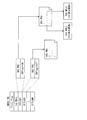
40 記録装置
41 ビデオエンコーダ
42 素材制作部
43 シナリオ生成部
44 BDプログラム制作部
45 多重化処理部
46 フォーマット処理部 1000 BD-ROM
2000
(実施の形態1)
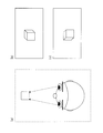
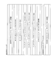
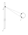
1.立体視の原理
まず、家庭用ディスプレイでの立体視の原理を説明する。立体視を実現する方法は、ホログラフィ技術を用いる方法と視差画像(両眼視差に応じた二本のビデオストリーム)を用いる方法とに大別できる。 Hereinafter, embodiments of the present invention will be described with reference to the drawings.
(Embodiment 1)
1. Principle of stereoscopic vision First, the principle of stereoscopic vision on a home display will be described. The method for realizing stereoscopic vision can be roughly classified into a method using a holography technique and a method using a parallax image (two video streams corresponding to binocular parallax).
2.ユーザに立体視を行わせるための視差画像(以下、「3D映像」ともいう)を格納するためのデータ構造
次に、本発明に係る記録媒体であるBD-ROMにおいて3D映像を格納するためのデータ構造について説明する。 In this embodiment, the continuous separation method and the polarized glasses method will be described as examples, but the present invention is not limited to these two methods as long as a parallax image is used.
2. Data structure for storing a parallax image (hereinafter also referred to as “3D video”) for allowing a user to perform stereoscopic viewing Next, for storing a 3D video in a BD-ROM which is a recording medium according to the present invention The data structure will be described.
3.左目用ビデオストリーム及び右目用ビデオストリームのPTS
続いて、動画像の立体視をユーザに行わせるための、左目用ビデオストリーム及び右目用ビデオストリームのPTSについて説明する。 In BD-ROM, a proprietary interpreter program called command navigation is used, but since the language system is not the essence of the present invention, it is written in a general-purpose programming language such as Java (registered trademark) or JavaScript. It can be a program. A play list to be reproduced is designated by this program.
3. PTS of video stream for left eye and video stream for right eye
Next, the PTS of the left-eye video stream and the right-eye video stream for allowing the user to perform stereoscopic viewing of a moving image will be described.
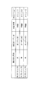
ここで、フレームレートが、例えば24pであれば、1秒間に24枚のピクチャを表示することを示している。よって、左目用のピクチャと当該左目用ピクチャに対応する右目用ピクチャとの間隔(表示遅延)は、1/48秒となる。 PTS (for right eye) = PTS (for left eye) + 1 / (number of frames per second × 2)
Here, if the frame rate is 24p, for example, 24 pictures are displayed per second. Therefore, the interval (display delay) between the left-eye picture and the right-eye picture corresponding to the left-eye picture is 1/48 seconds.
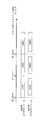
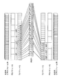
4.左目用ビデオストリームと右目用ビデオストリームとの多重化
AVクリップへのランダムアクセスを考慮した、左目用ビデオストリームと右目用ビデオストリームとの多重化をどのように行うのかについて説明する。 By the way, there is a case where playback is performed from the middle of the digital stream instead of from the beginning by a skip operation or a time-specified jump operation. In that case, since the entry map describes entry points in GOP units, it is necessary to consider the GOP boundary between the left-eye video stream and the right-eye video stream when multiplexing.
4). Multiplexing of left-eye video stream and right-eye video stream How to multiplex a left-eye video stream and a right-eye video stream in consideration of random access to an AV clip will be described.
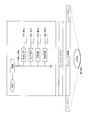
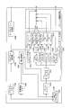
5.再生装置
続いて、3D映像を格納しているBD-ROM1000を再生する再生装置について説明する。図11は、再生装置2000の構成を示すブロック図である。図11に示すように、再生装置2000は、BD-ROMドライブ2100、トラックバッファ2200、システムターゲットデコーダ2300、プレーン加算部2400、プログラムメモリ2500、管理情報メモリ2600、プログラム実行部2700、再生制御部2800、及びユーザイベント処理部2900を含んで構成される。 As shown in FIG. 10, when multiplexing the left-eye video stream and the right-eye video stream, first, the leading packet (L11) of the leading GOP (LGOP1) of the left-eye video stream is arranged. Each packet (R11, R12, R13) of the GOP (RGOP1) of the right-eye video stream corresponding to LGOP1 is arranged after the packet (L11) arrangement position and ahead of the end packet (L16) of LGOP1. Following the end packet (L16) of LGOP1, the first packet (L21) of the next GOP (LGOP2) of the left-eye video stream is arranged, and in the same way as before, the front packet (L26) of LGOP2 is forwarded to LGOP2. Each packet (R21, R22, R23) of the GOP (RGOP2) of the corresponding right-eye video stream is arranged. By multiplexing the left-eye video stream and the right-eye video stream in this way, a digital stream is generated that ensures that the GOP of the right-eye video stream is not cut when cutting at the GOP boundary of the left-eye video stream. .
5). Playback Device Next, a playback device for playing back the BD-
6.家庭内で3D映像を視聴するための構成
続いて、家庭内で3D映像を視聴するための構成について説明する。ユーザが、家庭内で3D映像を視聴するためには、上述したBD-ROMとBD-ROMを再生する再生装置2000の他、再生装置から出力される3D映像を表示可能なディスプレイと立体視用のメガネとが必要になる。図13は、BD-ROM1000、再生装置2000、ディスプレイ3000、立体視用のメガネ4000、及びリモコン5000を含んで構成されるホームシステムを示す図である。 The above is the configuration of the
6). Configuration for Viewing 3D Video at Home Next, a configuration for viewing 3D video at home will be described. In order for a user to view 3D video at home, in addition to the above-described BD-ROM and
(実施の形態2)
本実施の形態では、本発明にかかる記録装置および記録方法を実施するための形態について説明する。 As described above, according to the present embodiment, even when playback is started from an arbitrary PTS on the time axis of the digital stream, the recording area of the digital stream after the position indicated by the SPN corresponding to the PTS includes Since the GOP of the left-eye video stream and the GOP of the right-eye video stream corresponding to the GOP exist, it is possible to surely make the user stereoscopically view the moving image.
(Embodiment 2)
In the present embodiment, a mode for carrying out a recording apparatus and a recording method according to the present invention will be described.
(実施の形態3)
本実施の形態では、BD-ROMディスクに2D映像と3D映像とが混在している場合に関して説明する。BD-ROMディスクに収録されている映画コンテンツにおいて、全ての映像が3Dあるいは2Dのどちらかであれば、ユーザは、各ディスクに応じて前述の立体視専用メガネを装着するか否かを選択すればよいが、一つのディスクの中に2D映像と3D映像とが混在している場合には、ユーザは何らかのタイミングでメガネを装着したり、外したりする必要が出てくる。 The
(Embodiment 3)
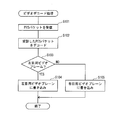
In this embodiment, a case where 2D video and 3D video are mixed on a BD-ROM disc will be described. In the movie content recorded on the BD-ROM disc, if all the images are either 3D or 2D, the user can select whether or not to wear the above-described stereoscopic viewing glasses according to each disc. However, when 2D video and 3D video are mixed in one disc, the user needs to wear or unplug glasses at some timing.
<補足>
以上、本発明に係る記録媒体について、実施の形態に基づいて説明したが、本発明は上記の実施の形態に限られないことは勿論である。
(変形例1)
実施の形態1では、左目用ビデオストリームと右目用ビデオストリームとが一本のデジタルストリームに多重化されていたが、ここでは、左目用ビデオストリームと右目用ビデオストリームとを多重化せず、別々のデジタルストリームとして記録媒体に記録されている場合について説明する。 Here, the 3D correspondence flag indicating 2D video or 3D video is set for each title, but a 3D correspondence flag may be set for each playlist, play item, or AV stream.
<Supplement>
While the recording medium according to the present invention has been described based on the embodiments, it is needless to say that the present invention is not limited to the above embodiments.
(Modification 1)
In the first embodiment, the left-eye video stream and the right-eye video stream are multiplexed into one digital stream. However, here, the left-eye video stream and the right-eye video stream are not multiplexed and are separately provided. A case where a digital stream is recorded on a recording medium will be described.
(変形例2)
変形例1では、3Dプレイリスト情報はメインパスに加えて、一つのサブパスを有するとしたが、ここでは、3Dプレイリスト情報が複数のサブパスを含む場合について説明する。 Therefore, even when the left-eye video stream and the right-eye video stream are not multiplexed and are separated into separate digital streams, the GOP and the left-eye video stream GOP and Since there is a GOP of the right-eye video stream corresponding to the GOP, the user can surely perform stereoscopic viewing of the moving image.
(Modification 2)
In the first modification, the 3D playlist information has one sub-path in addition to the main path. Here, a case where the 3D playlist information includes a plurality of sub-paths will be described.
(変形例3)
変形例2では、3Dプレイリスト情報が複数のサブパスを含む場合について説明したが、ここでは、各サブクリップにオーディオデータ、字幕、及びメニューを組み合わせた場合について説明する。 The subpath with the subpath ID “0” refers to the
(Modification 3)
In the second modification, the case where the 3D playlist information includes a plurality of sub paths has been described. Here, a case where audio data, subtitles, and menus are combined with each sub clip will be described.
(1)上記実施の形態1では、AVクリップは、左目用ビデオストリームに関するエントリマップを有し、左目用ビデオストリームの各GOPが、当該GOPに対応する、右目用ビデオストリームのGOPより先行する位置に配置されるとしたが、AVクリップが右目用ビデオストリームに関するエントリマップを有し、右目用ビデオストリームの各GOPが、当該GOPに対応する、左目用ビデオストリームのGOPより先行する位置に配置されるとしてもよい。
(2)上記実施の形態1では、再生装置は、左目用ビデオプレーンと右目用ビデオプレーンとを備える構成としたが、ビデオプレーンを一つだけ備えるとしてもよい。この場合、再生装置は、左目用ピクチャと右目用ピクチャとを交互にビデオプレーンに書き出す。 As described above, by preparing audio data corresponding to each sub-clip, a sense of presence and a sense of localization to a sound emitted by an object displayed in 3D are not increased. Sounds that are not related to the sound, such as background sound, are put into the AV clip as an audio stream, and only sounds generated by a specific object or person on the screen are put into the AV clip as a second audio stream. And the second audio stream may be reproduced while mixing at the same time to obtain the sound localization corresponding to each sub clip. This allows the second audio stream to be a relatively simple sound such as a human conversational sound or a fly-flying sound, so that an audio compression method with a higher compression rate can be used and multiple audio streams are stored. Can reduce the amount of data.
(1) In the first embodiment, the AV clip has an entry map related to the left-eye video stream, and each GOP of the left-eye video stream precedes the GOP of the right-eye video stream corresponding to the GOP. However, the AV clip has an entry map related to the right-eye video stream, and each GOP of the right-eye video stream is disposed at a position corresponding to the GOP and preceding the GOP of the left-eye video stream. It may be.
(2) In the first embodiment, the playback device includes the left-eye video plane and the right-eye video plane. However, the playback device may include only one video plane. In this case, the playback device writes left-eye pictures and right-eye pictures alternately on the video plane.
(3)上記実施の形態1では、ある時刻PTSで表示される左目用ピクチャに対して、対応する右目用ピクチャのPTSは、PTS(左目用)+1/(1秒当たりのフレーム数×2)であるとしたが、右目用ピクチャのPTSは、対応する左目用ピクチャとその次の左目用ピクチャの間であればよい。
(4)上記実施の形態1では、AVクリップは、左目用ビデオストリームに関するエントリマップを有するとしたが、左目用ビデオストリーム及び右目用ビデオストリームのエントリマップを有するとしてもよい。右目用のエントリマップのテーブル情報において、各エントリポイントには、AVクリップのエントリマップの左目用ビデオストリームのエントリポイントで指定されているPTSに、表示遅延(1/48)だけ加算した値であるPTSが設定される。 In addition, the playback apparatus is configured to include one video decoder, but may include two video decoders, a left-eye video decoder and a right-eye video decoder. In this case, the demultiplexer outputs the PES packet to either the left-eye video decoder or the right-eye video decoder based on the PID included in the TS packet.
(3) In the first embodiment, for the left-eye picture displayed at a certain time PTS, the PTS of the corresponding right-eye picture is PTS (for left eye) + 1 / (number of frames per second × 2) However, the PTS of the right-eye picture may be between the corresponding left-eye picture and the next left-eye picture.
(4) In the first embodiment, the AV clip has an entry map related to the left-eye video stream. However, the AV clip may have an entry map of the left-eye video stream and the right-eye video stream. In the table information of the entry map for the right eye, each entry point is a value obtained by adding a display delay (1/48) to the PTS specified by the entry point of the left-eye video stream in the AV clip entry map. PTS is set.
(5)上記実施の形態1では、図9、10において、左目用GOPの先頭パケットと、当該左目用GOPの終端パケットとの間に、当該左目用GOPに対応する右目用GOPを配置するとしたが、左目用GOPの先頭パケットと、次の左目用GOPの先頭パケットとの間に、当該右目用GOPを配置するとしてもよいし、次の左目用GOPの終端パケットまでに配置するとしてもよい。このように、左目用GOPと当該左目用GOPに対応する右目用の多重化の位置とを制限することで、AVデータへランダムアクセスが行われた際に、左目用GOP及び対応する右目用GOPの読み出しタイミングが大きくずれないことを保証することができる。
(6)上記実施の形態1では、3D映像を表示可能なディスプレイについて説明したが、実際には、2D映像しか表示できないディスプレイも存在する。その際、ユーザが、ディスプレイが3D再生に対応しているか否かを判断するのは困難である。そこで、ディスプレイが3D再生に対応しているか否かの判断を、ユーザが意識することなく、再生装置が行うことが望ましい。 As described above, if the memory of the playback device has enough capacity and each entry map can be read out to the memory, the left-eye video stream and the right-eye video stream are multiplexed without considering the storage position relationship. be able to.
(5) In the first embodiment, in FIGS. 9 and 10, the right-eye GOP corresponding to the left-eye GOP is arranged between the head packet of the left-eye GOP and the end packet of the left-eye GOP. However, the right-eye GOP may be arranged between the first packet of the left-eye GOP and the first packet of the next left-eye GOP, or may be arranged by the end packet of the next left-eye GOP. . In this way, by restricting the left-eye GOP and the right-eye multiplexing position corresponding to the left-eye GOP, when the AV data is randomly accessed, the left-eye GOP and the corresponding right-eye GOP It can be ensured that the read timing does not deviate greatly.
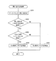
(6) In the first embodiment, the display capable of displaying 3D video has been described. However, there are actually displays capable of displaying only 2D video. At that time, it is difficult for the user to determine whether or not the display supports 3D playback. Therefore, it is desirable for the playback device to determine whether or not the display supports 3D playback without the user being aware of it.
(7)上記実施の形態1では、継時分離方式及び偏光メガネ方式を例として用いて説明したが、レンチキュラーレンズを用いて立体視を実現する場合には、左目用ビデオストリームの各ピクチャと当該ピクチャに対応する右目用ビデオストリームのピクチャとを、同一のPTSになるよう設定し、一画面中の縦方向に左目用のピクチャと対応する右目用のピクチャとを同時に交互に並べ、ディスプレイ表面にレンチキュラーレンズを貼り合わせることで、ディスプレイ上に表示された映像を、立体映像として認識することができる。
(8)3D再生のためのプレイリストは、BD-Jアプリケーションによって再生されてもよい。BD-Jアプリケーションとは、Java2Micro#Edition(J2ME) Personal Basis Profile(PBP 1.0)と、Globally Excecutable MHP specification(GEM1.0.2)for package media targetsとをフル実装したプログラム実行部において、BD-Jタイトルを生存区間として起動されるJavaアプリケーションである。 Further, when the 3D display flag is valid, when the playback device transmits 3D-compatible content to the display, information indicating that the content is 3D-compatible content may be included in the header or the like. As a result, when 3D-compatible content is received by the display, specific processing such as not performing edge enhancement as described above on the display side is reduced or reduced, or appropriate processing is added to 3D viewing. Is possible.
(7) In the first embodiment, the sequential separation method and the polarized glasses method have been described as examples. However, when stereoscopic viewing is realized using a lenticular lens, each picture of the left-eye video stream The right-eye video stream corresponding to the picture is set to have the same PTS, and the left-eye picture and the corresponding right-eye picture are alternately arranged in the vertical direction in one screen at the same time on the display surface. By attaching the lenticular lens, the image displayed on the display can be recognized as a stereoscopic image.
(8) A playlist for 3D playback may be played back by a BD-J application. BD-J application is a program execution part that fully implements Java2 Micro # Edition (J2ME) Personal Basis Profile (PBP 1.0) and Globally Excecutable MHP specification (GEM1.0.2) for package media targets. It is a Java application that is started as a life cycle.
Claims (8)
- 記録媒体であって、
デジタルストリームが記録されている領域と、マップ情報が記録されている領域とを含み、
マップ情報は、デジタルストリームが記録されている領域におけるエントリアドレスを、エントリ時刻と対応付けて示す情報であり、
デジタルストリームが記録されている領域のうち、エントリアドレスで指示される位置以降の領域には、第1グループ・オブ・ピクチャ及び第2グループ・オブ・ピクチャのペアが存在しており、
第1グループ・オブ・ピクチャは、デジタルストリームの時間軸において、エントリ時刻から再生されるべき動画像を表し、
第2グループ・オブ・ピクチャは、動画像の立体視をユーザに行わせる場合、第1グループ・オブ・ピクチャと共に再生されるべき動画像を表す
ことを特徴とする記録媒体。 A recording medium,
Including an area where a digital stream is recorded and an area where map information is recorded;
The map information is information indicating the entry address in the area where the digital stream is recorded in association with the entry time,
Of the area where the digital stream is recorded, in the area after the position indicated by the entry address, there is a pair of the first group of pictures and the second group of pictures,
The first group of pictures represents moving images to be played from the entry time on the time axis of the digital stream,
The second group of pictures represents a moving image to be reproduced together with the first group of pictures when the user performs stereoscopic viewing of the moving image. - 第1グループ・オブ・ピクチャ及び第2グループ・オブ・ピクチャは、複数のパケットに分割された状態で、多重化されており、
第1グループ・オブ・ピクチャを分割することで得られた複数のパケットのうち、先頭のものの記録位置は、第2グループ・オブ・ピクチャを分割することで得られた複数のパケットの先頭のものの記録位置よりも、デジタルストリーム上で先行しており、
マップ情報におけるエントリアドレスは、第1グループ・オブ・ピクチャを分割することで得られた複数のパケットのうち、先頭のもののパケット番号を用いて表現されている
ことを特徴とする請求項1記載の記録媒体。 The first group of pictures and the second group of pictures are multiplexed in a state of being divided into a plurality of packets,
Among the plurality of packets obtained by dividing the first group of pictures, the recording position of the first packet is that of the first packet of the plurality of packets obtained by dividing the second group of pictures. It precedes the recording position on the digital stream,
The entry address in the map information is expressed using the packet number of the first one among a plurality of packets obtained by dividing the first group of pictures. recoding media. - 前記第2グループ・オブ・ピクチャを分割することで得られた複数のパケットは何れも、前記第1グループ・オブ・ピクチャのエントリアドレスの直後のエントリアドレスより前に存在する
ことを特徴とする請求項2記載の記録媒体。 The plurality of packets obtained by dividing the second group of pictures are all present before the entry address immediately after the entry address of the first group of pictures. Item 3. A recording medium according to Item 2. - 前記第2グループ・オブ・ピクチャを分割することで得られた複数のパケットは何れも、前記第1グループ・オブ・ピクチャの終端パケットより前に存在する
ことを特徴とする請求項2記載の記録媒体。 3. The recording according to claim 2, wherein a plurality of packets obtained by dividing the second group of pictures are present before a terminal packet of the first group of pictures. Medium. - 前記第1グループ・オブ・ピクチャの各ピクチャと前記第2グループ・オブ・ピクチャの各ピクチャとは、一対一で対応しており、
前記第2グループ・オブ・ピクチャのうち所定ピクチャの表示時刻は、当該所定ピクチャに対応する、前記第1グループ・オブ・ピクチャにおけるピクチャの表示時刻に、1/(前記第1グループ・オブ・ピクチャのフレームレート×2)だけ加算した値である
ことを特徴とする請求項1記載の記録媒体。 Each picture of the first group of pictures has a one-to-one correspondence with each picture of the second group of pictures,
The display time of a predetermined picture of the second group of pictures is 1 / (the first group of pictures) corresponding to the display time of the picture in the first group of pictures corresponding to the predetermined picture. The recording medium according to claim 1, wherein the recording medium is a value obtained by adding the frame rate × 2). - デジタルストリームを生成する生成手段と、
生成したデジタルストリームを記録媒体に記録する記録手段とを有し、
前記デジタルストリームは、デジタルストリームの時間軸において、エントリ時刻から再生されるべき動画像を表す第1グループ・オブ・ピクチャと、動画像の立体視をユーザに行わせる場合、第1グループ・オブ・ピクチャと共に再生されるべき動画像を表す第2グループ・オブ・ピクチャと、マップ情報とを含み、
マップ情報は、デジタルストリームの記録領域内部におけるエントリアドレスを、エントリ時刻と対応付けて示す情報であり、
前記生成手段は、第1グループ・オブ・ピクチャ及び第2グループ・オブ・ピクチャを、複数のパケットに分割し、第1グループ・オブ・ピクチャを分割することで得られた複数のパケットのうち先頭のものが、第2グループ・オブ・ピクチャを分割することで得られた複数のパケットの先頭のものよりも、デジタルストリーム上で先行するよう多重化する
ことを特徴とする記録装置。 Generating means for generating a digital stream;
Recording means for recording the generated digital stream on a recording medium,
The digital stream includes a first group of pictures representing a moving picture to be reproduced from an entry time on the time axis of the digital stream, and a first group of pictures when the user performs stereoscopic viewing of the moving picture. A second group of pictures representing moving images to be played with the pictures, and map information,
The map information is information indicating the entry address in the recording area of the digital stream in association with the entry time,
The generating means divides the first group of pictures and the second group of pictures into a plurality of packets, and the first of the plurality of packets obtained by dividing the first group of pictures. The recording apparatus is characterized in that the packet is multiplexed so that it precedes on the digital stream rather than the head of the plurality of packets obtained by dividing the second group of pictures. - デジタルストリームの時間軸において、エントリ時刻から再生されるべき動画像である第1グループ・オブ・ピクチャと、動画像の立体視をユーザに行わせる場合、第1グループ・オブ・ピクチャと共に再生されるべき動画像である第2グループ・オブ・ピクチャとが、複数のパケットに分割された状態で多重化されたデジタルストリームについての再生装置であって、
各グループ・オブ・ピクチャをデコードして動画像を得るビデオデコーダと、
第1グループ・オブ・ピクチャから得られた画像を格納するための第1ビデオプレーンと、
第2グループ・オブ・ピクチャから得られた画像を格納するための第2ビデオプレーンと、
第1ビデオプレーン及び第2ビデオプレーンに格納された画像を交互に表示手段に出力する出力部とを備え、
各パケットは、当該パケットに含まれるデータが、前記第1グループ・オブ・ピクチャに関するものであるか、前記第2グループ・オブ・ピクチャに関するものであるかを示すパケット識別子を含み、
前記ビデオデコーダは、前記パケット識別子が前記第1グループ・オブ・ピクチャに関するものであることを示す場合、デコードした画像を第1ビデオプレーンに出力し、前記パケット識別子が前記第2グループ・オブ・ピクチャに関するものであることを示す場合、デコードした画像を第2ビデオプレーンに出力する
ことを特徴とする再生装置。 When the user performs stereoscopic viewing of the first group of pictures, which are moving images to be reproduced from the entry time on the time axis of the digital stream, and the moving images are reproduced together with the first group of pictures. A second group of pictures, which is a moving image, is a playback device for a digital stream multiplexed in a state of being divided into a plurality of packets,
A video decoder that obtains a moving image by decoding each group of pictures;
A first video plane for storing images obtained from the first group of pictures;
A second video plane for storing images obtained from the second group of pictures;
An output unit that alternately outputs the images stored in the first video plane and the second video plane to the display means,
Each packet includes a packet identifier indicating whether the data included in the packet is related to the first group of pictures or the second group of pictures,
The video decoder outputs the decoded image to the first video plane when the packet identifier indicates that the packet identifier is related to the first group of pictures, and the packet identifier is the second group of pictures. A playback apparatus that outputs the decoded image to the second video plane. - デジタルストリームの時間軸において、エントリ時刻から再生されるべき動画像である第1グループ・オブ・ピクチャと、動画像の立体視をユーザに行わせる場合、第1グループ・オブ・ピクチャと共に再生されるべき動画像である第2グループ・オブ・ピクチャとが、複数のパケットに分割された状態で多重化されたデジタルストリームについての再生方法であって、
各グループ・オブ・ピクチャをデコードして動画像を得るビデオデコードステップと、
第1グループ・オブ・ピクチャから得られた画像を格納するための第1ビデオプレーン及び第2グループ・オブ・ピクチャから得られた画像を格納するための第2ビデオプレーンに格納された画像を交互に表示手段に出力する出力ステップとを備え、
各パケットは、当該パケットに含まれるデータが、前記第1グループ・オブ・ピクチャに関するものであるか、前記第2グループ・オブ・ピクチャに関するものであるかを示すパケット識別子を含み、
前記ビデオデコードステップは、前記パケット識別子が前記第1グループ・オブ・ピクチャに関するものであることを示す場合、デコードした画像を第1ビデオプレーンに出力し、前記パケット識別子が前記第2グループ・オブ・ピクチャに関するものであることを示す場合、デコードした画像を第2ビデオプレーンに出力する
ことを特徴とする再生方法。 When the user performs stereoscopic viewing of the first group of pictures, which are moving images to be reproduced from the entry time on the time axis of the digital stream, and the moving images are reproduced together with the first group of pictures. A second group of pictures, which is a moving image, is a reproduction method for a digital stream multiplexed in a state of being divided into a plurality of packets,
A video decoding step for obtaining a moving image by decoding each group of pictures;
Images alternately stored in a first video plane for storing images obtained from the first group of pictures and in a second video plane for storing images obtained from the second group of pictures An output step for outputting to the display means,
Each packet includes a packet identifier indicating whether the data included in the packet is related to the first group of pictures or the second group of pictures,
The video decoding step outputs the decoded image to the first video plane when the packet identifier indicates that the packet identifier is related to the first group of pictures, and the packet identifier is the second group of pictures. A reproduction method comprising: outputting a decoded image to a second video plane when indicating that the image relates to a picture.
Priority Applications (11)
| Application Number | Priority Date | Filing Date | Title |
|---|---|---|---|
| ES09702249.5T ES2659717T3 (en) | 2008-01-17 | 2009-01-14 | Recording medium in which 3D video is recorded, recording device for recording 3D video and playback device and method for playing 3D video |
| CA2680696A CA2680696C (en) | 2008-01-17 | 2009-01-14 | Recording medium on which 3d video is recorded, recording medium for recording 3d video, and reproducing device and method for reproducing 3d video |
| AU2009205250A AU2009205250B2 (en) | 2008-01-17 | 2009-01-14 | Recording medium on which 3D video is recorded, recording medium for recording 3D video, and reproducing device and method for reproducing 3D video |
| JP2009549981A JP4527808B2 (en) | 2008-01-17 | 2009-01-14 | Recording medium on which 3D video is recorded, recording apparatus for recording 3D video, and playback apparatus and playback method for playing back 3D video |
| BRPI0902887A BRPI0902887A2 (en) | 2008-01-17 | 2009-01-14 | recording medium in which a 3d video is recorded, recording medium for recording a 3d video and then playback and method for playing a 3d video |
| CN2009800001745A CN101682719B (en) | 2008-01-17 | 2009-01-14 | Recording medium on which 3d video is recorded, recording medium for recording 3d video, and reproducing device and method for reproducing 3d video |
| MX2009009963A MX2009009963A (en) | 2008-01-17 | 2009-01-14 | Recording medium on which 3d video is recorded, recording medium for recording 3d video, and reproducing device and method for reproducing 3d video. |
| DK09702249.5T DK2230844T3 (en) | 2008-01-17 | 2009-01-14 | REGISTRATION MEDIUM, WHICH 3D VIDEO IS REGISTERED, REGISTRATION MEDIUM FOR REGISTERING 3D VIDEO AND REPLACEMENT DEVICE AND METHOD OF REPRESENTING 3D VIDEO |
| EP09702249.5A EP2230844B1 (en) | 2008-01-17 | 2009-01-14 | Recording medium on which 3d video is recorded, recording apparatus for recording 3d video, and reproducing device and method for reproducing 3d video |
| RU2009134736/07A RU2505870C2 (en) | 2008-01-17 | 2009-01-14 | Recording medium having recorded three-dimensional video, recording medium for recording three-dimensional video and reproducing device, and method of reproducing three-dimensional video |
| ZA2009/05799A ZA200905799B (en) | 2008-01-17 | 2009-08-20 | Recording medium on which 3d video is recorded,recording medium for recording 3d video,and reproducing device and method for reproducing 3d video |
Applications Claiming Priority (2)
| Application Number | Priority Date | Filing Date | Title |
|---|---|---|---|
| US2181708P | 2008-01-17 | 2008-01-17 | |
| US61/021,817 | 2008-01-17 |
Publications (1)
| Publication Number | Publication Date |
|---|---|
| WO2009090868A1 true WO2009090868A1 (en) | 2009-07-23 |
Family
ID=40885260
Family Applications (1)
| Application Number | Title | Priority Date | Filing Date |
|---|---|---|---|
| PCT/JP2009/000109 WO2009090868A1 (en) | 2008-01-17 | 2009-01-14 | Recording medium on which 3d video is recorded, recording medium for recording 3d video, and reproducing device and method for reproducing 3d video |
Country Status (15)
| Country | Link |
|---|---|
| US (2) | US8139930B2 (en) |
| EP (1) | EP2230844B1 (en) |
| JP (1) | JP4527808B2 (en) |
| KR (1) | KR20100096000A (en) |
| CN (1) | CN101682719B (en) |
| AU (1) | AU2009205250B2 (en) |
| BR (1) | BRPI0902887A2 (en) |
| CA (1) | CA2680696C (en) |
| DK (1) | DK2230844T3 (en) |
| ES (1) | ES2659717T3 (en) |
| MX (1) | MX2009009963A (en) |
| MY (1) | MY148196A (en) |
| RU (1) | RU2505870C2 (en) |
| WO (1) | WO2009090868A1 (en) |
| ZA (1) | ZA200905799B (en) |
Cited By (25)
| Publication number | Priority date | Publication date | Assignee | Title |
|---|---|---|---|---|
| WO2010113730A1 (en) * | 2009-04-03 | 2010-10-07 | ソニー株式会社 | Information processing device, information processing method, and program |
| WO2010116998A1 (en) * | 2009-04-08 | 2010-10-14 | ソニー株式会社 | Recording device, recording method, reproduction device, reproduction method, program, and recording medium |
| JP2010259056A (en) * | 2009-04-03 | 2010-11-11 | Sony Corp | Information processing device, information processing method, and program |
| WO2010143439A1 (en) * | 2009-06-12 | 2010-12-16 | パナソニック株式会社 | Reproduction device, integrated circuit, and recording medium |
| JP2011055148A (en) * | 2009-08-31 | 2011-03-17 | Toshiba Corp | Video combining device, video display apparatus, and video combining method |
| WO2011064913A1 (en) * | 2009-11-27 | 2011-06-03 | パナソニック株式会社 | Video signal processing device and video signal processing method |
| WO2011077673A1 (en) * | 2009-12-21 | 2011-06-30 | パナソニック株式会社 | Reproduction device |
| CN102118592A (en) * | 2009-12-31 | 2011-07-06 | 乐金显示有限公司 | System for displaying multivideo |
| WO2011132404A1 (en) * | 2010-04-20 | 2011-10-27 | パナソニック株式会社 | 3d image recording device and 3d image signal processing device |
| JP2011529286A (en) * | 2008-07-25 | 2011-12-01 | コーニンクレッカ フィリップス エレクトロニクス エヌ ヴィ | Subtitle 3D display processing |
| JP2012080267A (en) * | 2010-09-30 | 2012-04-19 | Nec Personal Computers Ltd | Display control device and display control method |
| JP2012100342A (en) * | 2009-04-03 | 2012-05-24 | Sony Corp | Information processing equipment, information processing method, and program |
| WO2012137829A1 (en) * | 2011-04-04 | 2012-10-11 | 日立コンシューマエレクトロニクス株式会社 | Video display system, display device, and display method |
| US8593511B2 (en) | 2009-06-11 | 2013-11-26 | Panasonic Corporation | Playback device, integrated circuit, recording medium |
| JP2014197878A (en) * | 2014-06-06 | 2014-10-16 | 日立マクセル株式会社 | Transmission and reception system and transmission and reception method |
| JP2015092681A (en) * | 2014-11-26 | 2015-05-14 | 日立マクセル株式会社 | Reception apparatus and reception method |
| JP2015149745A (en) * | 2015-03-27 | 2015-08-20 | 日立マクセル株式会社 | Reception apparatus and reception method |
| JP2015149744A (en) * | 2015-03-27 | 2015-08-20 | 日立マクセル株式会社 | Transmission/reception system and transmission/reception method |
| JP2015159558A (en) * | 2015-03-27 | 2015-09-03 | 日立マクセル株式会社 | Transmitting and receiving system and transmitting and receiving method |
| JP2016134190A (en) * | 2015-01-20 | 2016-07-25 | パナソニック インテレクチュアル プロパティ コーポレーション オブ アメリカPanasonic Intellectual Property Corporation of America | Reproduction control method, reproduction device and reproduction system |
| WO2016116974A1 (en) * | 2015-01-20 | 2016-07-28 | パナソニック インテレクチュアル プロパティ コーポレーション オブ アメリカ | Playback control method, playback device, and playback system |
| JP2016187202A (en) * | 2016-06-09 | 2016-10-27 | 日立マクセル株式会社 | Receiver and reception method |
| JP2016189609A (en) * | 2016-06-09 | 2016-11-04 | 日立マクセル株式会社 | Transmitting and receiving system and transmitting and receiving method |
| JP2017143551A (en) * | 2017-03-22 | 2017-08-17 | 日立マクセル株式会社 | Reception apparatus and receiving method |
| TWI626844B (en) * | 2012-06-28 | 2018-06-11 | Ntt都科摩股份有限公司 | Motion picture prediction decoding device and method |
Families Citing this family (43)
| Publication number | Priority date | Publication date | Assignee | Title |
|---|---|---|---|---|
| US10742953B2 (en) | 2009-01-20 | 2020-08-11 | Koninklijke Philips N.V. | Transferring of three-dimensional image data |
| US8451320B1 (en) * | 2009-01-23 | 2013-05-28 | Next3D, Inc. | Methods and apparatus for stereoscopic video compression, encoding, transmission, decoding and/or decompression |
| KR101626486B1 (en) * | 2009-01-28 | 2016-06-01 | 엘지전자 주식회사 | Broadcast receiver and video data processing method thereof |
| JP5465523B2 (en) * | 2009-01-29 | 2014-04-09 | 三洋電機株式会社 | Stereoscopic image display system |
| US8369693B2 (en) * | 2009-03-27 | 2013-02-05 | Dell Products L.P. | Visual information storage methods and systems |
| JP4984183B2 (en) * | 2009-04-07 | 2012-07-25 | ソニー株式会社 | REPRODUCTION DEVICE, REPRODUCTION METHOD, AND RECORDING METHOD |
| JP5469911B2 (en) * | 2009-04-22 | 2014-04-16 | ソニー株式会社 | Transmitting apparatus and stereoscopic image data transmitting method |
| JP5274359B2 (en) * | 2009-04-27 | 2013-08-28 | 三菱電機株式会社 | 3D video and audio recording method, 3D video and audio playback method, 3D video and audio recording device, 3D video and audio playback device, 3D video and audio recording medium |
| JP5400467B2 (en) * | 2009-05-01 | 2014-01-29 | キヤノン株式会社 | VIDEO OUTPUT DEVICE, ITS CONTROL METHOD, AND PROGRAM |
| US20110013888A1 (en) * | 2009-06-18 | 2011-01-20 | Taiji Sasaki | Information recording medium and playback device for playing back 3d images |
| US8676041B2 (en) | 2009-07-04 | 2014-03-18 | Dolby Laboratories Licensing Corporation | Support of full resolution graphics, menus, and subtitles in frame compatible 3D delivery |
| JP5089658B2 (en) * | 2009-07-16 | 2012-12-05 | 株式会社Gnzo | Transmitting apparatus and transmitting method |
| US8289374B2 (en) * | 2009-08-25 | 2012-10-16 | Disney Enterprises, Inc. | Method and system for encoding and transmitting high definition 3-D multimedia content |
| KR20110029319A (en) * | 2009-09-15 | 2011-03-23 | 삼성전자주식회사 | Video processing system and video processing method |
| TWI404405B (en) * | 2009-12-25 | 2013-08-01 | Mstar Semiconductor Inc | Image processing apparatus having on-screen display function and method thereof |
| JP2011139261A (en) * | 2009-12-28 | 2011-07-14 | Sony Corp | Image processing device, image processing method, and program |
| US20110157302A1 (en) * | 2009-12-30 | 2011-06-30 | Ati Technologies Ulc | Three-dimensional video display system with multi-stream sending/receiving operation |
| JP2011146831A (en) * | 2010-01-13 | 2011-07-28 | Sony Corp | Video processing apparatus, method of processing video, and computer program |
| KR20110088334A (en) * | 2010-01-28 | 2011-08-03 | 삼성전자주식회사 | Method and apparatus for generating datastream to provide 3-dimensional multimedia service, method and apparatus for receiving the same |
| US8712173B2 (en) * | 2010-03-12 | 2014-04-29 | Mediatek Singapore Pte. Ltd. | Methods for processing 2Nx2N block with N being positive integer greater than four under intra-prediction mode and related processing circuits thereof |
| JP5870272B2 (en) * | 2010-03-29 | 2016-02-24 | パナソニックIpマネジメント株式会社 | Video processing device |
| JP5577805B2 (en) * | 2010-04-08 | 2014-08-27 | ソニー株式会社 | Information processing apparatus, information recording medium, information processing method, and program |
| US9118896B2 (en) | 2010-04-21 | 2015-08-25 | Hitachi Maxell, Ltd. | Digital contents receiver, digital contents receiving method and digital contents transmitting and receiving method |
| JP5768332B2 (en) * | 2010-06-24 | 2015-08-26 | ソニー株式会社 | Transmitter, receiver and communication system |
| JP5537289B2 (en) * | 2010-06-30 | 2014-07-02 | 日立コンシューマエレクトロニクス株式会社 | Recording apparatus / method / medium, reproducing apparatus / method |
| JP5537290B2 (en) * | 2010-06-30 | 2014-07-02 | 日立コンシューマエレクトロニクス株式会社 | Recording apparatus / method / medium, reproducing apparatus / method |
| JP5637750B2 (en) * | 2010-06-30 | 2014-12-10 | 日立コンシューマエレクトロニクス株式会社 | Recording apparatus / method / medium, reproducing apparatus / method |
| JP5527727B2 (en) * | 2010-08-06 | 2014-06-25 | 日立コンシューマエレクトロニクス株式会社 | Video display system and display device |
| CN102447959A (en) * | 2010-10-01 | 2012-05-09 | 日立民用电子株式会社 | Receiver |
| US20120113218A1 (en) * | 2010-10-01 | 2012-05-10 | Manabu Sasamoto | Receiving apparatus and receiving method |
| US10424274B2 (en) | 2010-11-24 | 2019-09-24 | Ati Technologies Ulc | Method and apparatus for providing temporal image processing using multi-stream field information |
| US9485494B1 (en) | 2011-04-10 | 2016-11-01 | Nextvr Inc. | 3D video encoding and decoding methods and apparatus |
| US9407902B1 (en) | 2011-04-10 | 2016-08-02 | Nextvr Inc. | 3D video encoding and decoding methods and apparatus |
| US8681170B2 (en) | 2011-05-05 | 2014-03-25 | Ati Technologies Ulc | Apparatus and method for multi-streaming for more than three pixel component values |
| TWI501624B (en) * | 2011-05-13 | 2015-09-21 | Innolux Corp | Confidential display syatem, confidential display, confidential display method and confidential glasses |
| TWI487381B (en) * | 2011-05-19 | 2015-06-01 | Nat Univ Chung Cheng | Predictive Coding Method for Multimedia Image Texture |
| JPWO2013099289A1 (en) * | 2011-12-28 | 2015-04-30 | パナソニック株式会社 | REPRODUCTION DEVICE, TRANSMISSION DEVICE, REPRODUCTION METHOD, AND TRANSMISSION METHOD |
| US20150085071A1 (en) * | 2012-04-04 | 2015-03-26 | Ruiz Rodriquez Ezequiel | System for generating and receiving a stereoscopic 2d-backward-compatible video stream, and method thereof |
| CN103428463B (en) * | 2012-05-19 | 2016-10-12 | 腾讯科技(深圳)有限公司 | 3D video source stores method and apparatus and 3D video broadcasting method and device |
| US9860515B2 (en) * | 2012-12-11 | 2018-01-02 | Electronics And Telecommunications Research Institute | Apparatus and method for 3D content broadcasting with boundary information |
| CN104885474A (en) * | 2012-12-26 | 2015-09-02 | 汤姆逊许可公司 | Method and apparatus for content presentation |
| US20140212115A1 (en) * | 2013-01-31 | 2014-07-31 | Hewlett Packard Development Company, L.P. | Optical disc with three-dimensional viewing depth |
| US9858932B2 (en) | 2013-07-08 | 2018-01-02 | Dolby Laboratories Licensing Corporation | Processing of time-varying metadata for lossless resampling |
Citations (2)
| Publication number | Priority date | Publication date | Assignee | Title |
|---|---|---|---|---|
| WO1997032437A1 (en) * | 1996-02-28 | 1997-09-04 | Matsushita Electric Industrial Co., Ltd. | High-resolution optical disk for recording stereoscopic video, optical disk reproducing device, and optical disk recording device |
| JP2000270347A (en) * | 1999-03-17 | 2000-09-29 | Sharp Corp | Recorder and monitor system using the recorder |
Family Cites Families (13)
| Publication number | Priority date | Publication date | Assignee | Title |
|---|---|---|---|---|
| MX9801212A (en) * | 1995-09-29 | 1998-04-30 | Matsushita Electric Ind Co Ltd | Method and device for recording and reproducing interleaved bit stream on and from medium. |
| US5886736A (en) * | 1996-10-24 | 1999-03-23 | General Instrument Corporation | Synchronization of a stereoscopic video sequence |
| RU2237283C2 (en) * | 2001-11-27 | 2004-09-27 | Самсунг Электроникс Ко., Лтд. | Device and method for presenting three-dimensional object on basis of images having depth |
| JP3948979B2 (en) * | 2002-02-18 | 2007-07-25 | パイオニア株式会社 | Information recording medium, information recording apparatus and method, information reproducing apparatus and method, information recording / reproducing apparatus and method, computer program for recording or reproduction control, and data structure including control signal |
| JP4251864B2 (en) * | 2002-12-13 | 2009-04-08 | シャープ株式会社 | Image data creating apparatus and image data reproducing apparatus for reproducing the data |
| JP4594766B2 (en) * | 2004-03-10 | 2010-12-08 | パナソニック株式会社 | Authoring system, program, authoring method. |
| TWI401955B (en) * | 2004-04-16 | 2013-07-11 | Panasonic Corp | A reproducing apparatus, a recording medium, a reproducing method, and a reproducing system |
| US8150232B2 (en) * | 2004-09-03 | 2012-04-03 | Panasonic Corporation | Recording medium, recording device, program, and recording method |
| WO2007010779A1 (en) * | 2005-07-15 | 2007-01-25 | Matsushita Electric Industrial Co., Ltd. | Packet transmitter |
| KR20070022580A (en) * | 2005-08-22 | 2007-02-27 | 엘지전자 주식회사 | Method and apparatus for reproducing data, recording medium and method and eapparatus for recording data |
| US8208797B2 (en) * | 2005-10-27 | 2012-06-26 | Panasonic Corporation | Transport stream generating apparatus, recording apparatus having the same, and transport stream generating method |
| CN101842840B (en) * | 2007-11-01 | 2012-03-07 | 松下电器产业株式会社 | Recording medium, playback apparatus, recording apparatus, playback method, and recording method |
| JP5406044B2 (en) * | 2007-12-17 | 2014-02-05 | パナソニック株式会社 | Recording medium, recording device, playback device, and methods used for individual sales |
-
2009
- 2009-01-14 WO PCT/JP2009/000109 patent/WO2009090868A1/en active Application Filing
- 2009-01-14 CA CA2680696A patent/CA2680696C/en active Active
- 2009-01-14 RU RU2009134736/07A patent/RU2505870C2/en not_active IP Right Cessation
- 2009-01-14 ES ES09702249.5T patent/ES2659717T3/en active Active
- 2009-01-14 JP JP2009549981A patent/JP4527808B2/en active Active
- 2009-01-14 KR KR1020097017473A patent/KR20100096000A/en not_active Application Discontinuation
- 2009-01-14 MX MX2009009963A patent/MX2009009963A/en active IP Right Grant
- 2009-01-14 MY MYPI20093863A patent/MY148196A/en unknown
- 2009-01-14 DK DK09702249.5T patent/DK2230844T3/en active
- 2009-01-14 BR BRPI0902887A patent/BRPI0902887A2/en not_active Application Discontinuation
- 2009-01-14 CN CN2009800001745A patent/CN101682719B/en active Active
- 2009-01-14 AU AU2009205250A patent/AU2009205250B2/en not_active Ceased
- 2009-01-14 EP EP09702249.5A patent/EP2230844B1/en active Active
- 2009-01-15 US US12/354,264 patent/US8139930B2/en active Active
- 2009-08-20 ZA ZA2009/05799A patent/ZA200905799B/en unknown
-
2012
- 2012-02-08 US US13/368,457 patent/US20120141097A1/en not_active Abandoned
Patent Citations (2)
| Publication number | Priority date | Publication date | Assignee | Title |
|---|---|---|---|---|
| WO1997032437A1 (en) * | 1996-02-28 | 1997-09-04 | Matsushita Electric Industrial Co., Ltd. | High-resolution optical disk for recording stereoscopic video, optical disk reproducing device, and optical disk recording device |
| JP2000270347A (en) * | 1999-03-17 | 2000-09-29 | Sharp Corp | Recorder and monitor system using the recorder |
Cited By (38)
| Publication number | Priority date | Publication date | Assignee | Title |
|---|---|---|---|---|
| US9979902B2 (en) | 2008-07-25 | 2018-05-22 | Koninklijke Philips N.V. | 3D display handling of subtitles including text based and graphics based components |
| JP2011529286A (en) * | 2008-07-25 | 2011-12-01 | コーニンクレッカ フィリップス エレクトロニクス エヌ ヴィ | Subtitle 3D display processing |
| US8866885B2 (en) | 2009-04-03 | 2014-10-21 | Sony Corporation | Information processing device, information processing method, and program |
| JP2010259054A (en) * | 2009-04-03 | 2010-11-11 | Sony Corp | Information processing device, information processing method, and program |
| JP2012100342A (en) * | 2009-04-03 | 2012-05-24 | Sony Corp | Information processing equipment, information processing method, and program |
| US8971692B2 (en) | 2009-04-03 | 2015-03-03 | Sony Corporation | Information processing device, information processing method, and program |
| WO2010113730A1 (en) * | 2009-04-03 | 2010-10-07 | ソニー株式会社 | Information processing device, information processing method, and program |
| JP2010259056A (en) * | 2009-04-03 | 2010-11-11 | Sony Corp | Information processing device, information processing method, and program |
| US9756310B2 (en) | 2009-04-03 | 2017-09-05 | Sony Corporation | Information processing device, information processing method, and program |
| US8792780B2 (en) | 2009-04-08 | 2014-07-29 | Sony Corporation | Reproduction and recording apparatus and method for playing back and recording data encoded according to a predetermined standard |
| WO2010116998A1 (en) * | 2009-04-08 | 2010-10-14 | ソニー株式会社 | Recording device, recording method, reproduction device, reproduction method, program, and recording medium |
| US8593511B2 (en) | 2009-06-11 | 2013-11-26 | Panasonic Corporation | Playback device, integrated circuit, recording medium |
| WO2010143439A1 (en) * | 2009-06-12 | 2010-12-16 | パナソニック株式会社 | Reproduction device, integrated circuit, and recording medium |
| US8121461B2 (en) | 2009-06-12 | 2012-02-21 | Panasonic Corporation | Playback device, integrated circuit, recording medium |
| JP2011055148A (en) * | 2009-08-31 | 2011-03-17 | Toshiba Corp | Video combining device, video display apparatus, and video combining method |
| CN102668577A (en) * | 2009-11-27 | 2012-09-12 | 松下电器产业株式会社 | Video signal processing device and video signal processing method |
| US8994787B2 (en) | 2009-11-27 | 2015-03-31 | Panasonic Intellectual Property Management Co., Ltd. | Video signal processing device and video signal processing method |
| JP2011114606A (en) * | 2009-11-27 | 2011-06-09 | Panasonic Corp | Video signal processing apparatus and video signal processing method |
| WO2011064913A1 (en) * | 2009-11-27 | 2011-06-03 | パナソニック株式会社 | Video signal processing device and video signal processing method |
| WO2011077673A1 (en) * | 2009-12-21 | 2011-06-30 | パナソニック株式会社 | Reproduction device |
| CN102118592A (en) * | 2009-12-31 | 2011-07-06 | 乐金显示有限公司 | System for displaying multivideo |
| CN102118592B (en) * | 2009-12-31 | 2013-08-07 | 乐金显示有限公司 | System for displaying multivideo |
| JP5374641B2 (en) * | 2010-04-20 | 2013-12-25 | パナソニック株式会社 | 3D video recording apparatus and 3D video signal processing apparatus |
| WO2011132404A1 (en) * | 2010-04-20 | 2011-10-27 | パナソニック株式会社 | 3d image recording device and 3d image signal processing device |
| JP2012080267A (en) * | 2010-09-30 | 2012-04-19 | Nec Personal Computers Ltd | Display control device and display control method |
| US9225963B2 (en) | 2011-04-04 | 2015-12-29 | Hitachi Maxell, Ltd. | Video display system, display apparatus, and display method |
| WO2012137829A1 (en) * | 2011-04-04 | 2012-10-11 | 日立コンシューマエレクトロニクス株式会社 | Video display system, display device, and display method |
| TWI626844B (en) * | 2012-06-28 | 2018-06-11 | Ntt都科摩股份有限公司 | Motion picture prediction decoding device and method |
| JP2014197878A (en) * | 2014-06-06 | 2014-10-16 | 日立マクセル株式会社 | Transmission and reception system and transmission and reception method |
| JP2015092681A (en) * | 2014-11-26 | 2015-05-14 | 日立マクセル株式会社 | Reception apparatus and reception method |
| JP2016134190A (en) * | 2015-01-20 | 2016-07-25 | パナソニック インテレクチュアル プロパティ コーポレーション オブ アメリカPanasonic Intellectual Property Corporation of America | Reproduction control method, reproduction device and reproduction system |
| WO2016116974A1 (en) * | 2015-01-20 | 2016-07-28 | パナソニック インテレクチュアル プロパティ コーポレーション オブ アメリカ | Playback control method, playback device, and playback system |
| JP2015159558A (en) * | 2015-03-27 | 2015-09-03 | 日立マクセル株式会社 | Transmitting and receiving system and transmitting and receiving method |
| JP2015149744A (en) * | 2015-03-27 | 2015-08-20 | 日立マクセル株式会社 | Transmission/reception system and transmission/reception method |
| JP2015149745A (en) * | 2015-03-27 | 2015-08-20 | 日立マクセル株式会社 | Reception apparatus and reception method |
| JP2016187202A (en) * | 2016-06-09 | 2016-10-27 | 日立マクセル株式会社 | Receiver and reception method |
| JP2016189609A (en) * | 2016-06-09 | 2016-11-04 | 日立マクセル株式会社 | Transmitting and receiving system and transmitting and receiving method |
| JP2017143551A (en) * | 2017-03-22 | 2017-08-17 | 日立マクセル株式会社 | Reception apparatus and receiving method |
Also Published As
| Publication number | Publication date |
|---|---|
| EP2230844B1 (en) | 2017-11-22 |
| MX2009009963A (en) | 2009-10-08 |
| ES2659717T3 (en) | 2018-03-19 |
| EP2230844A4 (en) | 2014-07-30 |
| JPWO2009090868A1 (en) | 2011-05-26 |
| AU2009205250B2 (en) | 2013-02-21 |
| RU2505870C2 (en) | 2014-01-27 |
| JP4527808B2 (en) | 2010-08-18 |
| BRPI0902887A2 (en) | 2015-09-22 |
| US20090220213A1 (en) | 2009-09-03 |
| CA2680696C (en) | 2016-04-05 |
| CN101682719B (en) | 2013-01-30 |
| MY148196A (en) | 2013-03-15 |
| ZA200905799B (en) | 2011-10-26 |
| DK2230844T3 (en) | 2018-01-02 |
| AU2009205250A1 (en) | 2009-07-23 |
| AU2009205250A2 (en) | 2009-12-10 |
| US8139930B2 (en) | 2012-03-20 |
| EP2230844A1 (en) | 2010-09-22 |
| CA2680696A1 (en) | 2009-07-23 |
| CN101682719A (en) | 2010-03-24 |
| RU2009134736A (en) | 2011-03-27 |
| US20120141097A1 (en) | 2012-06-07 |
| KR20100096000A (en) | 2010-09-01 |
Similar Documents
| Publication | Publication Date | Title |
|---|---|---|
| JP4527808B2 (en) | Recording medium on which 3D video is recorded, recording apparatus for recording 3D video, and playback apparatus and playback method for playing back 3D video | |
| US8565576B2 (en) | Optical disc for reproducing stereoscopic video image | |
| JP5480915B2 (en) | Display device and method, recording medium, transmission device and method, and playback device and method | |
| US8503869B2 (en) | Stereoscopic video playback device and stereoscopic video display device | |
| JP5457465B2 (en) | Display device and method, transmission device and method, and reception device and method | |
| JP4993224B2 (en) | Playback apparatus and playback method | |
| JP5829604B2 (en) | Entry points for 3D trick play | |
| JP2010283856A (en) | Recording medium, reproduction device, and integrated circuit | |
| TW201123847A (en) | Recording medium, playback device, and integrated circuit | |
| WO2010116895A1 (en) | Recording device, recording method, reproduction device, reproduction method, recording medium, and program | |
| JP4984184B2 (en) | Playback apparatus and playback method | |
| JP4984194B2 (en) | Recording method | |
| JP4993233B2 (en) | Recording method | |
| JP2012100335A (en) | Reproduction device, reproduction method, and recording method | |
| JP2012135001A (en) | Recording method | |
| JP2012120233A (en) | Reproduction device, reproduction method, and recording method |
Legal Events
| Date | Code | Title | Description |
|---|---|---|---|
| WWE | Wipo information: entry into national phase |
Ref document number: 200980000174.5 Country of ref document: CN |
|
| REEP | Request for entry into the european phase |
Ref document number: 2009702249 Country of ref document: EP |
|
| WWE | Wipo information: entry into national phase |
Ref document number: 2009702249 Country of ref document: EP |
|
| WWE | Wipo information: entry into national phase |
Ref document number: 1020097017473 Country of ref document: KR |
|
| WWE | Wipo information: entry into national phase |
Ref document number: 2009205250 Country of ref document: AU |
|
| ENP | Entry into the national phase |
Ref document number: 2680696 Country of ref document: CA |
|
| ENP | Entry into the national phase |
Ref document number: 2009549981 Country of ref document: JP Kind code of ref document: A |
|
| 121 | Ep: the epo has been informed by wipo that ep was designated in this application |
Ref document number: 09702249 Country of ref document: EP Kind code of ref document: A1 |
|
| WWE | Wipo information: entry into national phase |
Ref document number: 2009134736 Country of ref document: RU Ref document number: PI20093863 Country of ref document: MY |
|
| WWE | Wipo information: entry into national phase |
Ref document number: 12009501777 Country of ref document: PH Ref document number: MX/A/2009/009963 Country of ref document: MX |
|
| ENP | Entry into the national phase |
Ref document number: 2009205250 Country of ref document: AU Date of ref document: 20090114 Kind code of ref document: A |
|
| NENP | Non-entry into the national phase |
Ref country code: DE |
|
| ENP | Entry into the national phase |
Ref document number: PI0902887 Country of ref document: BR Kind code of ref document: A2 Effective date: 20090916 |