WO2009004312A1 - Continuous inkjet drop generation device - Google Patents

Continuous inkjet drop generation device Download PDF

Info

Publication number
WO2009004312A1
WO2009004312A1 PCT/GB2008/002208 GB2008002208W WO2009004312A1 WO 2009004312 A1 WO2009004312 A1 WO 2009004312A1 GB 2008002208 W GB2008002208 W GB 2008002208W WO 2009004312 A1 WO2009004312 A1 WO 2009004312A1
Authority
WO
WIPO (PCT)
Prior art keywords
fluid
droplets
composite
cavity
flow
Prior art date
Application number
PCT/GB2008/002208
Other languages
French (fr)
Inventor
Andrew Clarke
Original Assignee
Eastman Kodak Company
Priority date (The priority date is an assumption and is not a legal conclusion. Google has not performed a legal analysis and makes no representation as to the accuracy of the date listed.)
Filing date
Publication date
Application filed by Eastman Kodak Company filed Critical Eastman Kodak Company
Priority to CN2008800230504A priority Critical patent/CN101765502B/en
Priority to JP2010514109A priority patent/JP5441898B2/en
Priority to US12/664,937 priority patent/US9010911B2/en
Priority to EP08762510.9A priority patent/EP2160294B1/en
Publication of WO2009004312A1 publication Critical patent/WO2009004312A1/en

Links

Classifications

    • BPERFORMING OPERATIONS; TRANSPORTING
    • B41PRINTING; LINING MACHINES; TYPEWRITERS; STAMPS
    • B41JTYPEWRITERS; SELECTIVE PRINTING MECHANISMS, i.e. MECHANISMS PRINTING OTHERWISE THAN FROM A FORME; CORRECTION OF TYPOGRAPHICAL ERRORS
    • B41J2/00Typewriters or selective printing mechanisms characterised by the printing or marking process for which they are designed
    • B41J2/005Typewriters or selective printing mechanisms characterised by the printing or marking process for which they are designed characterised by bringing liquid or particles selectively into contact with a printing material
    • B41J2/01Ink jet
    • B41J2/015Ink jet characterised by the jet generation process
    • B41J2/02Ink jet characterised by the jet generation process generating a continuous ink jet
    • B41J2/03Ink jet characterised by the jet generation process generating a continuous ink jet by pressure
    • BPERFORMING OPERATIONS; TRANSPORTING
    • B05SPRAYING OR ATOMISING IN GENERAL; APPLYING FLUENT MATERIALS TO SURFACES, IN GENERAL
    • B05BSPRAYING APPARATUS; ATOMISING APPARATUS; NOZZLES
    • B05B17/00Apparatus for spraying or atomising liquids or other fluent materials, not covered by the preceding groups
    • B05B17/04Apparatus for spraying or atomising liquids or other fluent materials, not covered by the preceding groups operating with special methods
    • BPERFORMING OPERATIONS; TRANSPORTING
    • B05SPRAYING OR ATOMISING IN GENERAL; APPLYING FLUENT MATERIALS TO SURFACES, IN GENERAL
    • B05BSPRAYING APPARATUS; ATOMISING APPARATUS; NOZZLES
    • B05B7/00Spraying apparatus for discharge of liquids or other fluent materials from two or more sources, e.g. of liquid and air, of powder and gas
    • B05B7/02Spray pistols; Apparatus for discharge
    • B05B7/04Spray pistols; Apparatus for discharge with arrangements for mixing liquids or other fluent materials before discharge
    • B05B7/0408Spray pistols; Apparatus for discharge with arrangements for mixing liquids or other fluent materials before discharge with arrangements for mixing two or more liquids
    • BPERFORMING OPERATIONS; TRANSPORTING
    • B05SPRAYING OR ATOMISING IN GENERAL; APPLYING FLUENT MATERIALS TO SURFACES, IN GENERAL
    • B05BSPRAYING APPARATUS; ATOMISING APPARATUS; NOZZLES
    • B05B7/00Spraying apparatus for discharge of liquids or other fluent materials from two or more sources, e.g. of liquid and air, of powder and gas
    • B05B7/02Spray pistols; Apparatus for discharge
    • B05B7/04Spray pistols; Apparatus for discharge with arrangements for mixing liquids or other fluent materials before discharge
    • B05B7/0416Spray pistols; Apparatus for discharge with arrangements for mixing liquids or other fluent materials before discharge with arrangements for mixing one gas and one liquid
    • B05B7/0433Spray pistols; Apparatus for discharge with arrangements for mixing liquids or other fluent materials before discharge with arrangements for mixing one gas and one liquid with one inner conduit of gas surrounded by an external conduit of liquid upstream the mixing chamber
    • BPERFORMING OPERATIONS; TRANSPORTING
    • B01PHYSICAL OR CHEMICAL PROCESSES OR APPARATUS IN GENERAL
    • B01FMIXING, e.g. DISSOLVING, EMULSIFYING OR DISPERSING
    • B01F33/00Other mixers; Mixing plants; Combinations of mixers
    • B01F33/30Micromixers
    • B01F33/301Micromixers using specific means for arranging the streams to be mixed, e.g. channel geometries or dispositions
    • B01F33/3011Micromixers using specific means for arranging the streams to be mixed, e.g. channel geometries or dispositions using a sheathing stream of a fluid surrounding a central stream of a different fluid, e.g. for reducing the cross-section of the central stream or to produce droplets from the central stream
    • BPERFORMING OPERATIONS; TRANSPORTING
    • B01PHYSICAL OR CHEMICAL PROCESSES OR APPARATUS IN GENERAL
    • B01FMIXING, e.g. DISSOLVING, EMULSIFYING OR DISPERSING
    • B01F33/00Other mixers; Mixing plants; Combinations of mixers
    • B01F33/30Micromixers
    • B01F33/3033Micromixers using heat to mix or move the fluids
    • BPERFORMING OPERATIONS; TRANSPORTING
    • B05SPRAYING OR ATOMISING IN GENERAL; APPLYING FLUENT MATERIALS TO SURFACES, IN GENERAL
    • B05BSPRAYING APPARATUS; ATOMISING APPARATUS; NOZZLES
    • B05B7/00Spraying apparatus for discharge of liquids or other fluent materials from two or more sources, e.g. of liquid and air, of powder and gas
    • B05B7/02Spray pistols; Apparatus for discharge
    • B05B7/06Spray pistols; Apparatus for discharge with at least one outlet orifice surrounding another approximately in the same plane
    • B05B7/061Spray pistols; Apparatus for discharge with at least one outlet orifice surrounding another approximately in the same plane with several liquid outlets discharging one or several liquids
    • BPERFORMING OPERATIONS; TRANSPORTING
    • B05SPRAYING OR ATOMISING IN GENERAL; APPLYING FLUENT MATERIALS TO SURFACES, IN GENERAL
    • B05BSPRAYING APPARATUS; ATOMISING APPARATUS; NOZZLES
    • B05B7/00Spraying apparatus for discharge of liquids or other fluent materials from two or more sources, e.g. of liquid and air, of powder and gas
    • B05B7/02Spray pistols; Apparatus for discharge
    • B05B7/06Spray pistols; Apparatus for discharge with at least one outlet orifice surrounding another approximately in the same plane
    • B05B7/062Spray pistols; Apparatus for discharge with at least one outlet orifice surrounding another approximately in the same plane with only one liquid outlet and at least one gas outlet
    • B05B7/065Spray pistols; Apparatus for discharge with at least one outlet orifice surrounding another approximately in the same plane with only one liquid outlet and at least one gas outlet an inner gas outlet being surrounded by an annular adjacent liquid outlet

Definitions

  • This invention relates to continuous inkjet devices, in particular to droplet generation.
  • inkjet printing has become a broadly applicable technology for supplying small quantities of liquid to a surface in an image-wise way.
  • Both drop-on-demand and continuous drop devices have been conceived and built.
  • the primary development of inkjet printing has been for aqueous based systems with some applications of solvent based systems, the underlying technology is being applied much more broadly.
  • a droplet generator is associated with the print head. The droplet generator stimulates the stream of fluid within and just beyond the print head, by a variety of mechanisms known in the art, at a frequency that forces continuous streams of fluid to be broken up into a series of droplets at a specific break-off point within the vicinity of the nozzle plate.
  • this stimulation is carried out at a fixed frequency that is calculated to be optimal for the particular fluid, and which matches a characteristic drop spacing of the fluid jet ejected from the nozzle orifice.
  • the distance between successively formed droplets, S is related to the droplet velocity, U dr op , and the stimulation frequency,/, by the relationship: U drc ⁇ —f.S.
  • U.S. 3,596,275 discloses three types of fixed frequency generation of droplets with a constant velocity and mass for a continuous inkjet recorder.
  • the first technique involves vibrating the nozzle itself.
  • the second technique imposes a pressure variation on the fluid in the nozzle by means of a piezoelectric transducer, placed typically within the cavity feeding the nozzle.
  • a third technique involves exciting a fluid jet electrohydrodynamically (EHD) with an EHD droplet stimulation electrode.
  • EHD fluid jet electrohydrodynamically
  • continuous inkjet systems employed in high quality printing operations typically require small closely spaced nozzles with highly uniform manufacturing tolerances. Fluid forced under pressure through these nozzles typically causes the ejection of small droplets, on the order of a few pico-liters in size, travelling at speeds from 10 to 50 metres per second. These droplets are generated at a rate ranging from tens to many hundreds of kilohertz.
  • Small, closely spaced nozzles, with highly consistent geometry and placement can be constructed using micro-machining technologies such as those found in the semiconductor industry.
  • nozzle channel plates produced by these techniques are made from materials such as silicon and other materials commonly employed in micromachining manufacture (MEMS). Multi-layer combinations of materials can be employed with different functional properties including electrical conductivity. Micro-machining technologies may include etching.
  • through-holes can be etched in the nozzle plate substrate to produce the nozzles.
  • These etching techniques may include wet chemical, inert plasma or chemically reactive plasma etching processes.
  • the micro-machining methods employed to produce the nozzle channel plates may also be used to produce other structures in the print head. These other structures may include ink feed channels and ink reservoirs.
  • an array of nozzle channels may be formed by etching through the surface of a substrate into a large recess or reservoir which itself is formed by etching from the other side of the substrate.
  • US 5801734 discloses a method of continuous inkjet printing.
  • US 3596275 discloses methods of stimulating a jet of liquid.
  • US 2006/0092230 discloses a method of charging an insulating ink liquid for use in a continuous inkjet device.
  • US 7192120 is representative of a number of patents disclosing novel drop on demand inkjet devices.
  • the distance from the nozzle plate at which the jet breaks to form droplets is critical since, conventionally, an electrode is required at this point in order to charge the droplets as they form.
  • the placement of this electrode with respect to the jet is also critical and therefore leads to significant engineering issues.
  • the perturbation required is achieved by vibrating the nozzle plate or other element of the fluid flow path with a piezoelectric system, usually at resonance and possibly with an acoustic cavity at resonance. This vibration provides a high energy pressure perturbation which initiates drop break up and thereby provides a regular supply of fixed size drops to print with.
  • the invention aims to provide a droplet generator for use in a continuous inkjet device wherein the initial perturbation is predominantly provided by the fluid flow.
  • a droplet generating device for use as part of a continuous inkjet printer comprising a set of channels for providing a composite flow of a first fluid surrounded by a second fluid and an expansion cavity having an entry orifice and an exit orifice, the cross sectional area of the cavity being larger than the cross sectional area of either orifice such that the composite flow breaks up to form droplets of the first fluid within the second fluid within the cavity, the exit orifice also forming a nozzle of an inkjet device, the passage of the droplets of the first fluid through the exit orifice causing the composite jet to break into composite droplets.
  • the present invention enables high energy jet break up without vibrational energy input and therefore without the use of piezoelectric devices.
  • the droplet generation device can therefore be made entirely via MEMS fabrication processes thereby allowing higher nozzle density than conventionally allowed. Further, such fabrication technology allows integration of the droplet generator with charging apparatus and thereby alleviates significant alignment issues of the two subsystems.
  • At least one embodiment of the device enables printing with lower quantities of liquid and thereby reduces issues related to drying the ink printed on 1 the substrate.
  • Figure 1 is a schematic diagram of a droplet generator device according to the invention.
  • Figure 2 is a copy of a photograph showing the jet as it exits the nozzle;
  • Figure 3 is a graph estimating the resonant behaviour of the device;
  • Figure 4 is a schematic drawing of a device shown to perform the invention;
  • Figure 5 is a schematic diagram of a generator device according to the invention;
  • Figure 6 is a schematic view of a printing system including the generator according to the invention.
  • Figure 7 illustrates an example device with heaters to provide a particular phase relation
  • Figure 8a is a copy of a photograph of internal drop formation with a heater perturbation active
  • 8b is an image compiled from a set of photographs as in figure 8a;
  • Figure 9 illustrates the measure of external breakoff length
  • Figure 10 illustrates data of external breakoff length as a function of internal drop size.
  • the break up of a jet of a first fluid within an immiscible second fluid within a channel can be regularised by providing, after the jet is formed, an expansion of the channel, a cavity, and an exit orifice such that as the droplets of the first fluid that are formed from the jet pass through the exit orifice, they perturb the flow within the cavity.
  • the droplet cross-sectional area should be an appreciable fraction of the exit orifice cross sectional area perpendicular to the flow direction. In preference the droplet cross-sectional area should be greater than about one third of the exit orifice cross sectional area perpendicular to the flow direction.
  • the flow perturbation is conducted back to the entrance orifice, i.e, where the channel first expands, and therefore perturbs the jet as it enters the cavity. Since the jet is intrinsically unstable this will subsequently cause the jet to break in a position commensurate with the same disturbance as convected by the jet. The droplet so formed will then in turn provide a flow perturbation as it exits the cavity at the exit orifice. Thus there will be provided reinforcement of the intrinsic break-up of the jet. The frequency at which this reinforcement occurs will correspond, via the jet velocity within the cavity, to a particular wavelength.
  • the flow feedback process means that the initial perturbation must have a fixed phase relation to the exit of a droplet of the first fluid and therefore the cavity will ensure a fixed frequency is chosen for a given set of flow conditions.
  • the frequency chosen, fin Hz will be approximately where Uj is the velocity of the jet of the first fluid (m/s), L is the length of the cavity (m), n is an integer and ⁇ is a number between 0 and 1 that takes account of end effects. This is quite analogous to the frequency selection within a laser cavity. It will be appreciated that the wavelength will depend on the diameter of the jet of the first fluid.
  • FIG. 1 is a schematic diagram of a droplet generator device in accordance with the invention.
  • a cross flow focusing device 1 is located upstream of an expansion cavity
  • the expansion cavity 3 is provided with an entrance orifice 2 and an exit orifice
  • the cross flow focussing device 1 is a standard device for creating a co- flowing liquid jet.
  • a jet of a first fluid, 11 3 surrounded by a second fluid 12 is passed into a broad channel or cavity 3, via the entrance orifice 2 such that the second fluid fills the volume around the jet.
  • the cavity 3 has an exit orifice 4.
  • L B is the break off length of the jet (m) of the first fluid measured from the entrance to the cavity
  • U is the fluid velocity (m/s)
  • R is the jet radius (m)
  • is the growth rate (s "1 ) for a frequency of interest (e.g. the Rayleigh frequency f R ⁇ U/(9.02R) [f R in Hz])
  • ⁇ j is the size of the initial perturbation (m).
  • is the viscosity of the first fluid (Pa.s)
  • is the interfacial tension (N/m)
  • the break off length L B may be estimated and compared with the cavity length, L.
  • the flow velocity, surface tension and length of the cavity should be mutually arranged such that the jet of the first fluid 11 breaks within the cavity. In a preferred embodiment 1/3L ⁇ LB ⁇ L.
  • the device as shown in Figure 1 therefore locks to a particular frequency and forms a suitable droplet generator for a continuous inlcjet printing device.
  • Figure 2 is a copy of a photograph showing the break up of the jet external to the device
  • Figure 3 is a graph illustrating an estimate of the resonant behaviour of the device.
  • an initial perturbation will grow exponentially with a growth rate a as used above.
  • an initial perturbation will grow as exp(a* ⁇ ), the normalised value of which, KQ, describes the growth of a perturbation at a particular frequency (i.e.
  • ao is the growth factor (1/s) at the Rayleigh wavelength (IcR 01 ) and ⁇ B is the time for the jet of the first fluid to break up into droplets (s) at the Rayleigh frequency
  • Also plotted is the gain of a free Rayleigh jet in air. Given incompressible fluids and hard walls, we would expect that a flow perturbation at the exit will be essentially equal to the flow perturbation at the input and therefore that Kf will be close to 1. It should be appreciated that the perturbation created at the exit, P 0 , will additionally perturb the jet external to the device and cause it to break up in a highly regular manner. That is, the resonant cavity drives a high energy perturbation of the exterior jet causing rapid and regular breakup.
  • Figure 4 is a schematic drawing of a device shown to perform the invention.
  • the device comprises a central arm 13 and upper and lower arms 14.
  • the upper and lower arms meet the central arm at junction 15.
  • This is a standard cross flow device.
  • An expansion cavity 16 is located immediately downstream of the junction 15.
  • the cavity has an entry nozzle 17 and an exit nozzle 18.
  • the cross flow device is thus coupled via the cavity 16 to the exit nozzle 18.
  • the cavity has a larger cross sectional area than the entry or exit nozzle.
  • the device was fabricated from glass.
  • any suitable material may be used to fabricate the device, including, but not limited to, hard materials such as ceramic, silicon, an oxide, a nitride, a carbide, an alloy or any material or set of materials suitable for use in one or more MEMs processing steps.
  • the flow -focussing device was supplied with deionised water containing 288mg of SDS in 100ml in both the upper and lower arms 14 at the same pressure.
  • Oil (decane) was supplied in the central arm 13 and formed a narrow thread that broke into regular droplets in the broadened region of the pipe, i.e, in the cavity 16.
  • the flow focussing device was, in a further experiment, supplied with air in the central arm 13 and deionised water in the upper and lower arms 14.
  • the air thread broke into bubbles in a regular way without forming a long thread of air within the cavity.
  • This regular stream of bubbles nevertheless provided sufficient perturbation to the composite jet at the exit orifice that the composite jet broke at a very short distance into a regular stream of composite droplets. It will be appreciated that the composite droplets contain less liquid and therefore for a given drop size reduce the drying requirements.
  • FIG. 5 is a schematic diagram of a generator device according to the invention.
  • This embodiment also includes an electrode 5 provided to charge the droplets as they form at the break up point.
  • This electrode may be a separate device aligned with the nozzle or in a preferred embodiment may be formed as part of the droplet generator device using for example MEMs technology.
  • heaters 9 and 10 are provided at the entry and exit orifice respectively. These enable the phase of the drop generation to be fixed such that, for example, subsequent charging and/or deflection can be provided synchronously.
  • the device according to the invention freely oscillates and therefore in a multi- nozzle printer each nozzle, even if at the same frequency, will be a random phase.
  • Figure 6 is a schematic view of a printing system including the droplet generator device according to the invention.
  • the droplet generator includes a MEMs fabricated electrode 5.
  • the droplets ejected are each charged by the electrode.
  • the stream of droplets subsequently passes through electrostatic deflection electrodes 6 and the droplets are selectively deflected.
  • the deflection electrodes 6 cause some of the droplets to reach the substrate 7 on which they are to be printed and the rest to be caught and recirculated to the ink supply by a catching device 13.
  • Figure 7 shows a schematic diagram of a device that cascades a flow focussing device to a cavity device as described in relation to Figure 1, and includes a means to perturb the liquid flows.
  • a 20mn film of platinum and a lOnm film of titanium were evaporated on one face of a glass capillary to form a zig-zag resistive heater pattern over each entrance constriction and the exit constriction, the fflm of titanium being next to the glass surface.
  • the zig zag pattern was a 2 micron wide track of overall length to give approximately 350 ohms resistance for the heater.
  • the overall width was kept to a minimum to allow for the highest possible frequency of interaction with the flow. This width was approximately 18 microns.
  • Each heater 30 could be energised independently. Whereas each heater had the desired effect, the heater over the cavity entrance constriction (2 in figure 1) was most efficient and was therefore used to collect the data shown in figures 8 and 9.
  • the frequency was 24.715kHz, the oil (drops) were decane and the external liquid was water.
  • the decane was supplied at 41. lpsi and the water at 65.3psi.
  • the frequency was then varied from 24.2kHz to 25.2kHz in 5Hz steps.
  • For each image obtained the central line of pixels through the drops was extracted and used to form a column of pixels in a new image.
  • the new image is shown in figure 8b where the y axis is distance along the channel centre and the x axis corresponds to frequency.
  • the central region of the image in figure 8b show the existence of drops in phase with the strobe LED, whereas the left and right regions show no droplets, Le. a blurred multiple exposure.
  • the diameter of the internal drop was optically measured together with the breakoff length. External breakoff length is plotted as a function of drop internal drop diameter in figure 10. Note that since the drops have a diameter greater than the channel height they are flattened, and therefore the measured internal drop diameter is approximately proportional to the internal drop cross sectional area. Figure 10 clearly indicates that the strong resonant behaviour occurs for internal drop cross-sections greater than about 1/3 of the exit orifice cross sectional area.
  • the invention has been described with reference to a composite jet of oil or air and an aqueous composition. It will be understood by those skilled in the art that the invention is not limited to such fluids.
  • the invention is particularly applicable to liquids designed as inks and containing, for example, surface active materials such as surfactants or dispersants or the like, polymers, monomers, reactive species, latexes, particulates.
  • the first fluid may be a gaseous composition. This should not be taken as an exhaustive list

Abstract

A droplet generating device for use as part of a continuous inkjet printer comprises a set of channels for providing a composite flow of a first fluid (11) surrounded by a second fluid (12) and an expansion cavity (3) having an entry orifice (2) and an exit orifice (4). The cross sectional area of the cavity is larger than the' cross sectional area of either orifice such that the composite flow breaks up to form droplets of the first fluid within the second -fluid within the cavity, the exit orifice also forming a nozzle of an inkjet device, the passage of the droplets of the first fluid through the exit orifice causing the composite jet to break into composite droplets.

Description

Continuous InkJet Drop Generation Device
FIELD OF THE INVENTION
This invention relates to continuous inkjet devices, in particular to droplet generation.
BACKGROUND OF THE INVENTION
With the growth in the consumer printer market inkjet printing has become a broadly applicable technology for supplying small quantities of liquid to a surface in an image-wise way. Both drop-on-demand and continuous drop devices have been conceived and built. Whilst the primary development of inkjet printing has been for aqueous based systems with some applications of solvent based systems, the underlying technology is being applied much more broadly. In order to create the stream of droplets, a droplet generator is associated with the print head. The droplet generator stimulates the stream of fluid within and just beyond the print head, by a variety of mechanisms known in the art, at a frequency that forces continuous streams of fluid to be broken up into a series of droplets at a specific break-off point within the vicinity of the nozzle plate. In the simplest case, this stimulation is carried out at a fixed frequency that is calculated to be optimal for the particular fluid, and which matches a characteristic drop spacing of the fluid jet ejected from the nozzle orifice. The distance between successively formed droplets, S, is related to the droplet velocity, U drop, and the stimulation frequency,/, by the relationship: Udrcφ—f.S. The droplet velocity is related to the jet velocity, Ujet, via σ Udmp = Ujel - pUietR where is the σ the surface tension (N/m), /?the liquid density (kg/m3) and if the jet's unperturbed radius (m).
U.S. 3,596,275, discloses three types of fixed frequency generation of droplets with a constant velocity and mass for a continuous inkjet recorder. The first technique involves vibrating the nozzle itself. The second technique imposes a pressure variation on the fluid in the nozzle by means of a piezoelectric transducer, placed typically within the cavity feeding the nozzle. A third technique involves exciting a fluid jet electrohydrodynamically (EHD) with an EHD droplet stimulation electrode.
Additionally, continuous inkjet systems employed in high quality printing operations typically require small closely spaced nozzles with highly uniform manufacturing tolerances. Fluid forced under pressure through these nozzles typically causes the ejection of small droplets, on the order of a few pico-liters in size, travelling at speeds from 10 to 50 metres per second. These droplets are generated at a rate ranging from tens to many hundreds of kilohertz. Small, closely spaced nozzles, with highly consistent geometry and placement can be constructed using micro-machining technologies such as those found in the semiconductor industry. Typically, nozzle channel plates produced by these techniques are made from materials such as silicon and other materials commonly employed in micromachining manufacture (MEMS). Multi-layer combinations of materials can be employed with different functional properties including electrical conductivity. Micro-machining technologies may include etching. Therefore through-holes can be etched in the nozzle plate substrate to produce the nozzles. These etching techniques may include wet chemical, inert plasma or chemically reactive plasma etching processes. The micro-machining methods employed to produce the nozzle channel plates may also be used to produce other structures in the print head. These other structures may include ink feed channels and ink reservoirs. Thus, an array of nozzle channels may be formed by etching through the surface of a substrate into a large recess or reservoir which itself is formed by etching from the other side of the substrate.
There are many known examples of inkjet printing. US 5801734 discloses a method of continuous inkjet printing. US 3596275 discloses methods of stimulating a jet of liquid. US 2006/0092230 discloses a method of charging an insulating ink liquid for use in a continuous inkjet device. US 7192120 is representative of a number of patents disclosing novel drop on demand inkjet devices.
PROBLEM TO BE SOLVED BY THE INVENTION Conventional continuous inkjet devices employ a drilled nozzle plate. Ink, or more generally a liquid, is applied to this plate under pressure causing jets of ink, or liquid, to emerge at high velocity. Such a jet of liquid is intrinsically unstable and will break up to form a series of droplets. This process is known as the Rayleigh-Plateau instability. Whilst the physics of this break up lead to a reasonably well defined frequency and droplet size, in order to be useful for printing, a perturbation must be provided such that the break up is controlled to give a fixed frequency and drop size. Moreover the distance from the nozzle plate at which the jet breaks to form droplets is critical since, conventionally, an electrode is required at this point in order to charge the droplets as they form. The placement of this electrode with respect to the jet is also critical and therefore leads to significant engineering issues. The perturbation required is achieved by vibrating the nozzle plate or other element of the fluid flow path with a piezoelectric system, usually at resonance and possibly with an acoustic cavity at resonance. This vibration provides a high energy pressure perturbation which initiates drop break up and thereby provides a regular supply of fixed size drops to print with.
The necessity of using a piezo system at high frequency, together with aspects of the drop break-up process impose severe restrictions on the ink, or liquid, properties. Thus the ink most commonly has a viscosity close to that of water. This in turn implies severe restrictions on the ink components allowable in the process. Further the use of piezo systems is fundamentally difficult to achieve with standard MEMs fabrication processes. Thus there is little possibility of significantly enhancing resolution by providing smaller, more closely spaced nozzles. A further problem of inlcjet printing in general and continuous inkjet printing in particular is the amount of water or solvent that is printed with many ink formulations. This is often necessary to ensure the ink viscosity is appropriate for the process. However there is then a further necessity to dry the ink on the printed surface without disturbing the pattern created.
SUMMARY OF THE INVENTION
The invention aims to provide a droplet generator for use in a continuous inkjet device wherein the initial perturbation is predominantly provided by the fluid flow.
According to the present invention there is provided a droplet generating device for use as part of a continuous inkjet printer comprising a set of channels for providing a composite flow of a first fluid surrounded by a second fluid and an expansion cavity having an entry orifice and an exit orifice, the cross sectional area of the cavity being larger than the cross sectional area of either orifice such that the composite flow breaks up to form droplets of the first fluid within the second fluid within the cavity, the exit orifice also forming a nozzle of an inkjet device, the passage of the droplets of the first fluid through the exit orifice causing the composite jet to break into composite droplets.
ADVANTAGEOUS EFFECT OF THE INVENTION The present invention enables high energy jet break up without vibrational energy input and therefore without the use of piezoelectric devices. The droplet generation device can therefore be made entirely via MEMS fabrication processes thereby allowing higher nozzle density than conventionally allowed. Further, such fabrication technology allows integration of the droplet generator with charging apparatus and thereby alleviates significant alignment issues of the two subsystems.
At least one embodiment of the device enables printing with lower quantities of liquid and thereby reduces issues related to drying the ink printed on1 the substrate. BRIEF DESCRIPTION OF THE DRAWINGS
The invention will now be described with reference to the accompanying drawings in which:
Figure 1 is a schematic diagram of a droplet generator device according to the invention;
Figure 2 is a copy of a photograph showing the jet as it exits the nozzle; Figure 3 is a graph estimating the resonant behaviour of the device; Figure 4 is a schematic drawing of a device shown to perform the invention; Figure 5 is a schematic diagram of a generator device according to the invention;
Figure 6 is a schematic view of a printing system including the generator according to the invention;
Figure 7 illustrates an example device with heaters to provide a particular phase relation; Figure 8a is a copy of a photograph of internal drop formation with a heater perturbation active, 8b is an image compiled from a set of photographs as in figure 8a;
Figure 9 illustrates the measure of external breakoff length; and Figure 10 illustrates data of external breakoff length as a function of internal drop size.
DETAILED DESCRIPTION OF THE INVENTION
The ability to form a fluid jet of a first fluid within an immiscible second fluid within a microfluidic device is known in the art. However, the modes of operation usual for these devices are either a "geometry controlled" or a
"dripping" mode, where monodisperse drops of the first fluid are directly formed. These modes are explained in S. L. Anna, H.C.Mayer, Phys. Fluids 18, 121512 (2006). However, it is also well understood that as the fluid flow velocity increases the first fluid passes the orifice responsible for the "geometry controlled" or "dripping" modes and forms a jet in the area beyond. This jet then breaks up into droplets controlled predominantly by interfacial or surface tension. This jet break up mode is termed the Rayleigh-Plateau instability and produces polydisperse droplets of the first fluid. If the first fluid is gaseous then of course the droplets of the first fluid are bubbles. It is a remarkable and hitherto unknown fact that the break up of a jet of a first fluid within an immiscible second fluid within a channel can be regularised by providing, after the jet is formed, an expansion of the channel, a cavity, and an exit orifice such that as the droplets of the first fluid that are formed from the jet pass through the exit orifice, they perturb the flow within the cavity. In order to achieve a significant flow perturbation, the droplet cross-sectional area should be an appreciable fraction of the exit orifice cross sectional area perpendicular to the flow direction. In preference the droplet cross-sectional area should be greater than about one third of the exit orifice cross sectional area perpendicular to the flow direction. The flow perturbation is conducted back to the entrance orifice, i.e, where the channel first expands, and therefore perturbs the jet as it enters the cavity. Since the jet is intrinsically unstable this will subsequently cause the jet to break in a position commensurate with the same disturbance as convected by the jet. The droplet so formed will then in turn provide a flow perturbation as it exits the cavity at the exit orifice. Thus there will be provided reinforcement of the intrinsic break-up of the jet. The frequency at which this reinforcement occurs will correspond, via the jet velocity within the cavity, to a particular wavelength. The flow feedback process means that the initial perturbation must have a fixed phase relation to the exit of a droplet of the first fluid and therefore the cavity will ensure a fixed frequency is chosen for a given set of flow conditions. The frequency chosen, fin Hz, will be approximately
Figure imgf000008_0001
where Uj is the velocity of the jet of the first fluid (m/s), L is the length of the cavity (m), n is an integer and β is a number between 0 and 1 that takes account of end effects. This is quite analogous to the frequency selection within a laser cavity. It will be appreciated that the wavelength will depend on the diameter of the jet of the first fluid. Further it will be appreciated that the length of jet required before break-up is observed is dependent on the interfacial tension between the first fluid and the second fluid, the viscosities of the first fluid and the second fluid and the velocity of flow. Thus the break-up length and therefore the length of the cavity is reduced by using a higher interfacial tension, a lower viscosity of the first fluid or a slower flow velocity. It is further possible to modify the flow velocity within the cavity without changing the exit velocity by increasing the dimension of the cavity perpendicular to the flow. Figure 1 is a schematic diagram of a droplet generator device in accordance with the invention.
A cross flow focusing device 1 is located upstream of an expansion cavity
3. The expansion cavity 3 is provided with an entrance orifice 2 and an exit orifice
4. A nozzle 5 is located immediately beyond the exit orifice 4. The cross flow focussing device 1 is a standard device for creating a co- flowing liquid jet.
In figure 1 a jet of a first fluid, 113 surrounded by a second fluid 12, is passed into a broad channel or cavity 3, via the entrance orifice 2 such that the second fluid fills the volume around the jet. The cavity 3 has an exit orifice 4. It is useful to consider the linear equations of a jet in air;
Figure imgf000009_0001
where LB is the break off length of the jet (m) of the first fluid measured from the entrance to the cavity, U is the fluid velocity (m/s), R is the jet radius (m), α is the growth rate (s"1) for a frequency of interest (e.g. the Rayleigh frequency fR~U/(9.02R) [fR in Hz]) and ξj is the size of the initial perturbation (m). The growth rate may be obtained from the following equation
Figure imgf000010_0001
where η is the viscosity of the first fluid (Pa.s), σ is the interfacial tension (N/m) and Ic is the wavevector (m'1) ( k=2πf/U). Thus the break off length LB may be estimated and compared with the cavity length, L. The flow velocity, surface tension and length of the cavity should be mutually arranged such that the jet of the first fluid 11 breaks within the cavity. In a preferred embodiment 1/3L<LB<L. The device as shown in Figure 1 therefore locks to a particular frequency and forms a suitable droplet generator for a continuous inlcjet printing device. Figure 2 is a copy of a photograph showing the break up of the jet external to the device. Note that the length required for break-up is remarkably shorter than for a jet of the same composition issuing at substantially the same velocity but without regular break-up of the first fluid within the cavity.
Figure 3 is a graph illustrating an estimate of the resonant behaviour of the device. In a linear approximation of jet break-up typically it is assumed that an initial perturbation will grow exponentially with a growth rate a as used above. Thus an initial perturbation will grow as exp(a*τ), the normalised value of which, KQ, describes the growth of a perturbation at a particular frequency (i.e. dimensionless wavevector JcR) relative to the growth rate of the same size of perturbation at the Rayleigh frequency (dimensionless wavevector, kRmj, ξ = ξ, exp(αf ), ξ0 = ξ, exp(αot) a = a(kR), a0 = cx(kRm)
K0 =f- = eiφ({a-a0)rB)
where ao is the growth factor (1/s) at the Rayleigh wavelength (IcR01) and τB is the time for the jet of the first fluid to break up into droplets (s) at the Rayleigh frequency
t, -ϊ-hfτ] where Ro is the jet radius. So an initial perturbation to the first fluid, PJO, grows and forms a droplet which then exits the device creating a flow perturbation, P0o proportional to the droplet size.
Figure imgf000011_0001
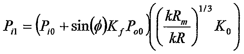
A proportion, Kf, of this perturbation is fed back within the cavity to the input perturbation, the sum of which in turn causes a flow perturbation. Hence, the summed input perturbation, P1, is
Figure imgf000011_0002
where φ is the relative phase of the output perturbation seen fed back to the input (=k.L with L the effective cavity length). This progression therefore leads to an infinite sum which gives the overall gain of the system relative to the gain of a free Rayleigh jet at the Rayleigh frequency as
Figure imgf000011_0003
In figure 3, Gain is plotted against the dimensionless wavevector, kR for the following parameter values: L=500μm, Ro=4.4μm, Kf=0.97, σ=50mN/m, p=0.973kg/m3, η=0.9mPα.s, . Also plotted is the gain of a free Rayleigh jet in air. Given incompressible fluids and hard walls, we would expect that a flow perturbation at the exit will be essentially equal to the flow perturbation at the input and therefore that Kf will be close to 1. It should be appreciated that the perturbation created at the exit, P0, will additionally perturb the jet external to the device and cause it to break up in a highly regular manner. That is, the resonant cavity drives a high energy perturbation of the exterior jet causing rapid and regular breakup.
Figure 4 is a schematic drawing of a device shown to perform the invention. The device comprises a central arm 13 and upper and lower arms 14. The upper and lower arms meet the central arm at junction 15. This is a standard cross flow device. An expansion cavity 16 is located immediately downstream of the junction 15. The cavity has an entry nozzle 17 and an exit nozzle 18. The cross flow device is thus coupled via the cavity 16 to the exit nozzle 18. The cavity has a larger cross sectional area than the entry or exit nozzle. The device was fabricated from glass. It will be understood by those skilled in the art that any suitable material may be used to fabricate the device, including, but not limited to, hard materials such as ceramic, silicon, an oxide, a nitride, a carbide, an alloy or any material or set of materials suitable for use in one or more MEMs processing steps.
The flow -focussing device was supplied with deionised water containing 288mg of SDS in 100ml in both the upper and lower arms 14 at the same pressure. Oil (decane) was supplied in the central arm 13 and formed a narrow thread that broke into regular droplets in the broadened region of the pipe, i.e, in the cavity 16. As the oil droplets traversed the exit orifice 18 they initiated break-up of the forming composite jet such that an oil drop was encapsulated in each water drop. Furthermore the composite jet break-up was observed to occur significantly closer to the exit orifice when regular oil drops were forming.
The flow focussing device was, in a further experiment, supplied with air in the central arm 13 and deionised water in the upper and lower arms 14. In this case the air thread broke into bubbles in a regular way without forming a long thread of air within the cavity. This regular stream of bubbles nevertheless provided sufficient perturbation to the composite jet at the exit orifice that the composite jet broke at a very short distance into a regular stream of composite droplets. It will be appreciated that the composite droplets contain less liquid and therefore for a given drop size reduce the drying requirements.
Figure 5 is a schematic diagram of a generator device according to the invention. This embodiment also includes an electrode 5 provided to charge the droplets as they form at the break up point. This electrode may be a separate device aligned with the nozzle or in a preferred embodiment may be formed as part of the droplet generator device using for example MEMs technology. Additionally, heaters 9 and 10 are provided at the entry and exit orifice respectively. These enable the phase of the drop generation to be fixed such that, for example, subsequent charging and/or deflection can be provided synchronously. The device according to the invention freely oscillates and therefore in a multi- nozzle printer each nozzle, even if at the same frequency, will be a random phase. In order to ensure the time of the drop is known and therefore can be placed as desired on the substrate the phase of each nozzle should preferably be set. Then for example, the voltage applied to the deflection plates can be timed to deflect the desired droplet. Alternatively a sensor may be provided on the exit orifice that also enables subsequent charging and/or deflection to be provided synchronously. Further, an imposed perturbation on the first fluid either directly, or via the second fluid will, if sufficiently great, cause the jet of the first fluid to break at the frequency of the imposed perturbation. Of course the condition / = („ + £)£/. stated previously will enable certain frequencies to be generated more easily.
Figure 6 is a schematic view of a printing system including the droplet generator device according to the invention.
In this embodiment the droplet generator includes a MEMs fabricated electrode 5. The droplets ejected are each charged by the electrode. The stream of droplets subsequently passes through electrostatic deflection electrodes 6 and the droplets are selectively deflected. The deflection electrodes 6 cause some of the droplets to reach the substrate 7 on which they are to be printed and the rest to be caught and recirculated to the ink supply by a catching device 13. Figure 7 shows a schematic diagram of a device that cascades a flow focussing device to a cavity device as described in relation to Figure 1, and includes a means to perturb the liquid flows. A 20mn film of platinum and a lOnm film of titanium were evaporated on one face of a glass capillary to form a zig-zag resistive heater pattern over each entrance constriction and the exit constriction, the fflm of titanium being next to the glass surface. The zig zag pattern was a 2 micron wide track of overall length to give approximately 350 ohms resistance for the heater. The overall width was kept to a minimum to allow for the highest possible frequency of interaction with the flow. This width was approximately 18 microns. Each heater 30 could be energised independently. Whereas each heater had the desired effect, the heater over the cavity entrance constriction (2 in figure 1) was most efficient and was therefore used to collect the data shown in figures 8 and 9.
By pulsing the heater in phase with stroboscopic lighting it was possible to phase lock the internal drop breakup. The image is acquired using a standard frame transfer video camera running at 25Hz, whereas the droplet formation is at around 25kHz. A high brightness LED is used as the light source and flashes once for each droplet. Therefore each video frame is a multiple exposure of approximately 1000 pictures. If the droplets are synchronised with the light flashes then a single clear image is obtained, otherwise the multiple exposures lead to a blurred image with no distinct drops seen. The breakup phenomena could then be investigated as a function of the heater pulse frequency. Figure 8a shows an image of internal drop breakup with the stroboscopic lighting phase locked with the heater pulse. The frequency was 24.715kHz, the oil (drops) were decane and the external liquid was water. The decane was supplied at 41. lpsi and the water at 65.3psi. The frequency was then varied from 24.2kHz to 25.2kHz in 5Hz steps. For each image obtained the central line of pixels through the drops was extracted and used to form a column of pixels in a new image. The new image is shown in figure 8b where the y axis is distance along the channel centre and the x axis corresponds to frequency. The central region of the image in figure 8b show the existence of drops in phase with the strobe LED, whereas the left and right regions show no droplets, Le. a blurred multiple exposure. Hence outside of a narrow band of frequencies the heater pulse was unable to phase lock the droplet formation This is a direct signature of resonant drop formation. A further set of example data demonstrates the dependence of the resonant behaviour on internal drop size. When each internal drop passes the exit orifice it creates a pressure pulse that perturbs the flow and leads to resonance. If the exit orifice also forms a jet, then the pressure pulse also perturbs the jet and thereby causes the jet to break prematurely. Hence the external jet breakoff length is a good measure of the strength of the pressure perturbation. The external breakoff length measure is illustrated in figure 9. The ratio of the oil and water supply pressure was varied, keeping the total flow rate approximately constant. The diameter of the internal drops was thereby varied. The diameter of the internal drop was optically measured together with the breakoff length. External breakoff length is plotted as a function of drop internal drop diameter in figure 10. Note that since the drops have a diameter greater than the channel height they are flattened, and therefore the measured internal drop diameter is approximately proportional to the internal drop cross sectional area. Figure 10 clearly indicates that the strong resonant behaviour occurs for internal drop cross-sections greater than about 1/3 of the exit orifice cross sectional area.
The invention has been described with reference to a composite jet of oil or air and an aqueous composition. It will be understood by those skilled in the art that the invention is not limited to such fluids. The invention is particularly applicable to liquids designed as inks and containing, for example, surface active materials such as surfactants or dispersants or the like, polymers, monomers, reactive species, latexes, particulates. Further, the first fluid may be a gaseous composition. This should not be taken as an exhaustive list
The invention has been described in detail with reference to preferred embodiments thereof. It will be understood by those skilled in the art that variations and modifications can be effected within the scope of the invention.

Claims

CLAIMS:
1. A droplet generating device for use as part of a continuous inkjet printer comprising a set of channels for providing a composite flow of a first fluid surrounded by a second fluid and an expansion cavity having an entry orifice and an exit orifice, the cross sectional area of the cavity being larger than the cross sectional area of either orifice such that the composite flow breaks up to form droplets of the first fluid within the second fluid within the cavity, the exit orifice also forming a nozzle of an inkjet device, the passage of the droplets of the first fluid through the exit orifice causing the composite jet to break into composite droplets.
2 A device as claimed in claim 1 wherein the cross sectional area of the exit orifice, perpendicular to the flow direction, is less than approximately three times the cross sectional area of the droplets of the first fluid.
3 A device as claimed in claim 1 or 2 wherein the first fluid is a liquid composition and breaks up into droplets at a distance approximately LB from the entrance of the cavity, the cavity being of length L and LB being greater than about (1/3)L, and
LB being less than L.
4. A device as claimed in claim 1, 2 or 3 including additional means to control the break up of the first fluid within the second fluid.
5. A device as claimed in claim 4 wherein the control means comprises a heater that perturbs the flow of the first fluid and/or the second fluid and/or the composite of the first fluid and second fluid.
6. A device as claimed in claim 4 wherein the control means comprises an electrostatic field that perturbs the flow of the first fluid and/or the second fluid and/or the composite of the first fluid and second fluid.
7. A device as claimed in claim 4 wherein the control means comprises a mechanical perturbation that perturbs the flow of the first fluid and/or the second fluid and/or the composite of the first fluid and second fluid.
8. A device as claimed in any preceding claim wherein charging means are provided adjacent the exit nozzle to charge the composite droplets.
9. A device as claimed in any preceding claim fabricated from a hard material.
10. A device as claimed in claim 9 wherein the channels are fabricated substantially from a hard material chosen from one or more of glass, ceramic, silicon, an oxide, a nitride, a carbide, an alloy, a material or set of materials suitable for use in one or more MEMs processing steps.
11. A method of forming droplets at high frequency and high velocity in gas comprising supplying a first fluid and a second fluid within a set of channels, the interface of the fluids being characterised by an interfacial tension or an interfacial elasticity, the second fluid surrounding the first fluid to form a composite jet, the jet passing through an expansion cavity having an entry orifice and an exit orifice, the cross sectional area of the cavity being larger than the cross sectional area of either orifice, the first fluid breaking into droplets within the second fluid within the cavity, the composite of the first and second fluids forming a jet on exit from the exit orifice and the passage of the droplets of the first fluid through the exit orifice causing the composite jet to break into droplets.
12. A method as claimed in claim 11 wherein the fluids flow through a cavity in which the cross sectional area of the exit orifice, perpendicular to the flow direction, is less than approximately three times the cross sectional area of the droplets of the first fluid.
13 A method as claimed in claim 11 or 12 wherein the first fluid breaks up into droplets at a distance approximately LB from the entrance of the cavity, the cavity being of length L and
LB being greater than about (1/3)L, and LB being less than L.
14. A method as claimed in claim 11, 12 or 13 additionally including control of the break up of the first fluid within the second fluid.
15. A method as claimed in claim 14 wherein a heater perturbs the flow of the first fluid and/or the second fluid and/or the composite of the first fluid and second fluid.
16. A method as claimed in claim 14 wherein an electrostatic field perturbs the flow of the first fluid and/or the second fluid and/or the composite of the first fluid and second fluid.
17. A method as claimed in claim 14 wherein a mechanical perturbation perturbs the flow of the first fluid and/or the second fluid and/or the composite of the first fluid and second fluid.
18. A method as claimed in any preceding claim wherein the composite droplets are charged adjacent the exit nozzle. 19 A continuous inkjet printing apparatus comprising one or more droplet generation devices according to any of claims 1 to 10.
PCT/GB2008/002208 2007-07-03 2008-06-27 Continuous inkjet drop generation device WO2009004312A1 (en)

Priority Applications (4)

Application Number Priority Date Filing Date Title
CN2008800230504A CN101765502B (en) 2007-07-03 2008-06-27 Continuous inkjet drop generation device
JP2010514109A JP5441898B2 (en) 2007-07-03 2008-06-27 Droplet generating device, droplet forming method, and continuous ink jet printing apparatus
US12/664,937 US9010911B2 (en) 2007-07-03 2008-06-27 Continuous inkjet drop generation device
EP08762510.9A EP2160294B1 (en) 2007-07-03 2008-06-27 Continuous inkjet drop generation device

Applications Claiming Priority (2)

Application Number Priority Date Filing Date Title
GBGB0712860.6A GB0712860D0 (en) 2007-07-03 2007-07-03 continuous inkjet drop generation device
GB0712860.6 2007-07-03

Publications (1)

Publication Number Publication Date
WO2009004312A1 true WO2009004312A1 (en) 2009-01-08

Family

ID=38421113

Family Applications (1)

Application Number Title Priority Date Filing Date
PCT/GB2008/002208 WO2009004312A1 (en) 2007-07-03 2008-06-27 Continuous inkjet drop generation device

Country Status (6)

Country Link
US (1) US9010911B2 (en)
EP (1) EP2160294B1 (en)
JP (1) JP5441898B2 (en)
CN (1) CN101765502B (en)
GB (1) GB0712860D0 (en)
WO (1) WO2009004312A1 (en)

Cited By (6)

* Cited by examiner, † Cited by third party
Publication number Priority date Publication date Assignee Title
WO2010110843A1 (en) * 2009-03-25 2010-09-30 Eastman Kodak Company Droplet generator
WO2012087350A3 (en) * 2010-12-21 2012-08-16 President And Fellows Of Harvard College Spray drying techniques
US8602535B2 (en) 2012-03-28 2013-12-10 Eastman Kodak Company Digital drop patterning device and method
US8936354B2 (en) 2012-03-28 2015-01-20 Eastman Kodak Company Digital drop patterning device and method
US8936353B2 (en) 2012-03-28 2015-01-20 Eastman Kodak Company Digital drop patterning device and method
US8939551B2 (en) 2012-03-28 2015-01-27 Eastman Kodak Company Digital drop patterning device and method

Families Citing this family (31)

* Cited by examiner, † Cited by third party
Publication number Priority date Publication date Assignee Title
JP2008535644A (en) 2005-03-04 2008-09-04 プレジデント・アンド・フエローズ・オブ・ハーバード・カレツジ Method and apparatus for the formation of multiple emulsions
CN102124259B (en) 2008-05-16 2015-12-16 哈佛大学 Valve in the fluid system comprising microfluid system and other flowing control
BR112012004719A2 (en) 2009-09-02 2016-04-05 Harvard College multiple emulsions created by blasting and other techniques
FR2958186A1 (en) * 2010-03-30 2011-10-07 Ecole Polytech DEVICE FOR FORMING DROPS IN A MICROFLUID CIRCUIT.
JP2012024313A (en) * 2010-07-23 2012-02-09 Nitto Denko Corp Device for forming droplets, and method for forming droplets
BR112013029729A2 (en) 2011-05-23 2017-01-24 Basf Se emulsion control including multiple emulsions
BR112013030233A2 (en) * 2011-05-25 2019-09-24 Eastman Kodak Co continuous liquid ejection system, and liquid droplet ejection method
CN103764265A (en) 2011-07-06 2014-04-30 哈佛学院院长等 Multiple emulsions and techniques for the formation of multiple emulsions
US8932677B2 (en) 2012-06-08 2015-01-13 Eastman Kodak Company Digital drop patterning and deposition device
US8633955B2 (en) 2012-06-08 2014-01-21 Eastman Kodak Company Digital drop patterning and deposition device
US8659631B2 (en) 2012-06-08 2014-02-25 Eastman Kodak Company Digital drop patterning and deposition device
CN103480314B (en) * 2013-10-15 2015-06-03 郑州大学 Method for regulating and controlling biological microballoons in biological microfluidic control machine
US10035887B2 (en) * 2015-08-19 2018-07-31 Shimadzu Corporation Manufacturing method for nanoparticle
US10850236B2 (en) 2015-08-31 2020-12-01 Palo Alto Research Center Incorporated Low dispersion, fast response mixing device
DE102016014952A1 (en) 2016-12-14 2018-06-14 Dürr Systems Ag Coating device for coating components
DE102016014943A1 (en) 2016-12-14 2018-06-14 Dürr Systems Ag Printhead with tempering device
DE102016014948A1 (en) 2016-12-14 2018-06-14 Dürr Systems Ag Printhead and related operating procedures
DE102016014946A1 (en) 2016-12-14 2018-06-14 Dürr Systems Ag Printhead for applying a coating agent to a component
DE102016014944A1 (en) 2016-12-14 2018-06-14 Dürr Systems Ag Coating method and corresponding coating device
DE102016014956A1 (en) 2016-12-14 2018-06-14 Dürr Systems Ag Coating device and associated operating method
DE102016014947A1 (en) 2016-12-14 2018-06-14 Dürr Systems Ag Printhead for applying a coating agent
DE102016014951A1 (en) 2016-12-14 2018-06-14 Dürr Systems Ag Coating device and associated operating method
DE102016014919A1 (en) 2016-12-14 2018-06-14 Dürr Systems Ag Application device and method for applying a coating agent
DE102016014955A1 (en) 2016-12-14 2018-06-14 Dürr Systems Ag Coating device and corresponding coating method
CN106733459B (en) * 2016-12-28 2019-07-12 浙江达普生物科技有限公司 A kind of replaceable micro-fluidic dispensing spool
CN106824674B (en) * 2016-12-28 2019-12-13 浙江天宏机械有限公司 Liquid-separating and glue-dispensing method based on micro-fluidic chip
CN106733458B (en) * 2016-12-28 2019-07-09 浙江达普生物科技有限公司 A kind of glue dispensing valve based on micro-fluidic chip
CN107070293A (en) * 2017-05-23 2017-08-18 中国科学技术大学 The microlayer model active preparation facilities and method disturbed based on piezoelectricity singing piece
CN109590148B (en) * 2019-01-23 2023-08-22 山东交通学院 Robot for rust removal and maintenance of track fasteners and working method
US11440321B2 (en) * 2019-12-12 2022-09-13 Xerox Corporation Gas expansion material jetting actuator
CN114602368B (en) * 2020-12-03 2022-12-09 上海远赞智造医药科技有限公司 Droplet generating device and method

Citations (3)

* Cited by examiner, † Cited by third party
Publication number Priority date Publication date Assignee Title
US4614953A (en) * 1984-04-12 1986-09-30 The Laitram Corporation Solvent and multiple color ink mixing system in an ink jet
WO1998053946A1 (en) 1997-05-27 1998-12-03 Mydata Automation Ab Applying drops of a primary liquid together with a secondary liquid to a substrate
US20010015735A1 (en) 2000-02-18 2001-08-23 Nobuo Matsumoto Ink jet recording method and apparatus

Family Cites Families (7)

* Cited by examiner, † Cited by third party
Publication number Priority date Publication date Assignee Title
JPS51108529U (en) * 1975-02-28 1976-08-31
US4305079A (en) * 1979-09-24 1981-12-08 International Business Machines Corp. Movable ink jet gutter
US7594507B2 (en) * 2001-01-16 2009-09-29 Hewlett-Packard Development Company, L.P. Thermal generation of droplets for aerosol
JP3777427B2 (en) 2003-11-25 2006-05-24 独立行政法人食品総合研究所 Emulsion production method and production apparatus
JP4777238B2 (en) * 2004-03-23 2011-09-21 独立行政法人科学技術振興機構 Method and apparatus for generating microdroplets
US7759111B2 (en) * 2004-08-27 2010-07-20 The Regents Of The University Of California Cell encapsulation microfluidic device
JP4713397B2 (en) * 2006-01-18 2011-06-29 株式会社リコー Microchannel structure and microdroplet generation system

Patent Citations (3)

* Cited by examiner, † Cited by third party
Publication number Priority date Publication date Assignee Title
US4614953A (en) * 1984-04-12 1986-09-30 The Laitram Corporation Solvent and multiple color ink mixing system in an ink jet
WO1998053946A1 (en) 1997-05-27 1998-12-03 Mydata Automation Ab Applying drops of a primary liquid together with a secondary liquid to a substrate
US20010015735A1 (en) 2000-02-18 2001-08-23 Nobuo Matsumoto Ink jet recording method and apparatus

Cited By (9)

* Cited by examiner, † Cited by third party
Publication number Priority date Publication date Assignee Title
WO2010110843A1 (en) * 2009-03-25 2010-09-30 Eastman Kodak Company Droplet generator
WO2010110842A1 (en) 2009-03-25 2010-09-30 Eastman Kodak Company Droplet generator
US8529026B2 (en) 2009-03-25 2013-09-10 Eastman Kodak Company Droplet generator
US8697008B2 (en) 2009-03-25 2014-04-15 Eastman Kodak Company Droplet generator
WO2012087350A3 (en) * 2010-12-21 2012-08-16 President And Fellows Of Harvard College Spray drying techniques
US8602535B2 (en) 2012-03-28 2013-12-10 Eastman Kodak Company Digital drop patterning device and method
US8936354B2 (en) 2012-03-28 2015-01-20 Eastman Kodak Company Digital drop patterning device and method
US8936353B2 (en) 2012-03-28 2015-01-20 Eastman Kodak Company Digital drop patterning device and method
US8939551B2 (en) 2012-03-28 2015-01-27 Eastman Kodak Company Digital drop patterning device and method

Also Published As

Publication number Publication date
JP2010531729A (en) 2010-09-30
EP2160294B1 (en) 2014-05-14
US9010911B2 (en) 2015-04-21
US20100188466A1 (en) 2010-07-29
CN101765502B (en) 2012-12-12
GB0712860D0 (en) 2007-08-08
JP5441898B2 (en) 2014-03-12
CN101765502A (en) 2010-06-30
EP2160294A1 (en) 2010-03-10

Similar Documents

Publication Publication Date Title
US9010911B2 (en) Continuous inkjet drop generation device
Basaran Small-scale free surface flows with breakup: Drop formation and emerging applications
US8302880B2 (en) Monodisperse droplet generation
US8439487B2 (en) Continuous ink jet printing of encapsulated droplets
US6863385B2 (en) Continuous ink-jet printing method and apparatus
EP2144758B1 (en) Continuous printer with actuator activation waveform
JP4918093B2 (en) Droplet electrification device for inkjet printing
Raje et al. A review on electrohydrodynamic-inkjet printing technology
US20030222950A1 (en) Apparatus and method for improving gas flow uniformity in a continuous stream ink jet printer
Castrejón-Pita et al. A novel method to produce small droplets from large nozzles
US20080088680A1 (en) Continuous drop emitter with reduced stimulation crosstalk
EP2125375A1 (en) Aerodynamic error reduction for liquid drop emitters
WO2006124747A1 (en) High speed liquid pattern deposition apparatus
Sun et al. Comparison of micro-dispensing performance between micro-valve and piezoelectric printhead
Shin et al. Operability diagram of drop formation and its response to temperature variation in a piezoelectric inkjet nozzle
US8974041B2 (en) Droplet selection mechanism
최경현 Printing of Fine Resolution Patterns through Electrohydrodynamic (EHD) Patterning Technology
Hawkins et al. Application of Instabilities in Microfluidic Jets to Digital Offset-Class Printing
JPH0631917A (en) Liquid jet recording head

Legal Events

Date Code Title Description
WWE Wipo information: entry into national phase

Ref document number: 200880023050.4

Country of ref document: CN

121 Ep: the epo has been informed by wipo that ep was designated in this application

Ref document number: 08762510

Country of ref document: EP

Kind code of ref document: A1

WWE Wipo information: entry into national phase

Ref document number: 2008762510

Country of ref document: EP

WWE Wipo information: entry into national phase

Ref document number: 2010514109

Country of ref document: JP

WWE Wipo information: entry into national phase

Ref document number: 12664937

Country of ref document: US

NENP Non-entry into the national phase

Ref country code: DE