WO2006105935A1 - Pedicle screw - Google Patents

Pedicle screw Download PDF

Info

Publication number
WO2006105935A1
WO2006105935A1 PCT/EP2006/003059 EP2006003059W WO2006105935A1 WO 2006105935 A1 WO2006105935 A1 WO 2006105935A1 EP 2006003059 W EP2006003059 W EP 2006003059W WO 2006105935 A1 WO2006105935 A1 WO 2006105935A1
Authority
WO
WIPO (PCT)
Prior art keywords
shaft
pedicle screw
relief zone
screw according
region
Prior art date
Application number
PCT/EP2006/003059
Other languages
German (de)
French (fr)
Inventor
Simon Casutt
Original Assignee
Zimmer Gmbh
Priority date (The priority date is an assumption and is not a legal conclusion. Google has not performed a legal analysis and makes no representation as to the accuracy of the date listed.)
Filing date
Publication date
Application filed by Zimmer Gmbh filed Critical Zimmer Gmbh
Priority to EP06724014.3A priority Critical patent/EP1865862B1/en
Priority to US11/910,004 priority patent/US20090062868A1/en
Priority to JP2008503445A priority patent/JP4964226B2/en
Publication of WO2006105935A1 publication Critical patent/WO2006105935A1/en

Links

Classifications

    • AHUMAN NECESSITIES
    • A61MEDICAL OR VETERINARY SCIENCE; HYGIENE
    • A61BDIAGNOSIS; SURGERY; IDENTIFICATION
    • A61B17/00Surgical instruments, devices or methods, e.g. tourniquets
    • A61B17/56Surgical instruments or methods for treatment of bones or joints; Devices specially adapted therefor
    • A61B17/58Surgical instruments or methods for treatment of bones or joints; Devices specially adapted therefor for osteosynthesis, e.g. bone plates, screws, setting implements or the like
    • A61B17/68Internal fixation devices, including fasteners and spinal fixators, even if a part thereof projects from the skin
    • A61B17/70Spinal positioners or stabilisers ; Bone stabilisers comprising fluid filler in an implant
    • A61B17/7001Screws or hooks combined with longitudinal elements which do not contact vertebrae
    • AHUMAN NECESSITIES
    • A61MEDICAL OR VETERINARY SCIENCE; HYGIENE
    • A61BDIAGNOSIS; SURGERY; IDENTIFICATION
    • A61B17/00Surgical instruments, devices or methods, e.g. tourniquets
    • A61B17/56Surgical instruments or methods for treatment of bones or joints; Devices specially adapted therefor
    • A61B17/58Surgical instruments or methods for treatment of bones or joints; Devices specially adapted therefor for osteosynthesis, e.g. bone plates, screws, setting implements or the like
    • A61B17/68Internal fixation devices, including fasteners and spinal fixators, even if a part thereof projects from the skin
    • A61B17/84Fasteners therefor or fasteners being internal fixation devices
    • A61B17/86Pins or screws or threaded wires; nuts therefor
    • A61B17/8625Shanks, i.e. parts contacting bone tissue
    • A61B17/863Shanks, i.e. parts contacting bone tissue with thread interrupted or changing its form along shank, other than constant taper
    • AHUMAN NECESSITIES
    • A61MEDICAL OR VETERINARY SCIENCE; HYGIENE
    • A61BDIAGNOSIS; SURGERY; IDENTIFICATION
    • A61B17/00Surgical instruments, devices or methods, e.g. tourniquets
    • A61B17/56Surgical instruments or methods for treatment of bones or joints; Devices specially adapted therefor
    • A61B17/58Surgical instruments or methods for treatment of bones or joints; Devices specially adapted therefor for osteosynthesis, e.g. bone plates, screws, setting implements or the like
    • A61B17/68Internal fixation devices, including fasteners and spinal fixators, even if a part thereof projects from the skin
    • A61B17/70Spinal positioners or stabilisers ; Bone stabilisers comprising fluid filler in an implant
    • A61B17/7001Screws or hooks combined with longitudinal elements which do not contact vertebrae
    • A61B17/7002Longitudinal elements, e.g. rods
    • A61B17/7004Longitudinal elements, e.g. rods with a cross-section which varies along its length
    • A61B17/7008Longitudinal elements, e.g. rods with a cross-section which varies along its length with parts of, or attached to, the longitudinal elements, bearing against an outside of the screw or hook heads, e.g. nuts on threaded rods
    • AHUMAN NECESSITIES
    • A61MEDICAL OR VETERINARY SCIENCE; HYGIENE
    • A61BDIAGNOSIS; SURGERY; IDENTIFICATION
    • A61B17/00Surgical instruments, devices or methods, e.g. tourniquets
    • A61B17/56Surgical instruments or methods for treatment of bones or joints; Devices specially adapted therefor
    • A61B17/58Surgical instruments or methods for treatment of bones or joints; Devices specially adapted therefor for osteosynthesis, e.g. bone plates, screws, setting implements or the like
    • A61B17/68Internal fixation devices, including fasteners and spinal fixators, even if a part thereof projects from the skin
    • A61B17/70Spinal positioners or stabilisers ; Bone stabilisers comprising fluid filler in an implant
    • A61B17/7001Screws or hooks combined with longitudinal elements which do not contact vertebrae
    • A61B17/7002Longitudinal elements, e.g. rods
    • A61B17/7019Longitudinal elements having flexible parts, or parts connected together, such that after implantation the elements can move relative to each other
    • A61B17/7031Longitudinal elements having flexible parts, or parts connected together, such that after implantation the elements can move relative to each other made wholly or partly of flexible material
    • AHUMAN NECESSITIES
    • A61MEDICAL OR VETERINARY SCIENCE; HYGIENE
    • A61BDIAGNOSIS; SURGERY; IDENTIFICATION
    • A61B17/00Surgical instruments, devices or methods, e.g. tourniquets
    • A61B17/56Surgical instruments or methods for treatment of bones or joints; Devices specially adapted therefor
    • A61B17/58Surgical instruments or methods for treatment of bones or joints; Devices specially adapted therefor for osteosynthesis, e.g. bone plates, screws, setting implements or the like
    • A61B17/68Internal fixation devices, including fasteners and spinal fixators, even if a part thereof projects from the skin
    • A61B17/84Fasteners therefor or fasteners being internal fixation devices
    • A61B17/86Pins or screws or threaded wires; nuts therefor
    • A61B17/864Pins or screws or threaded wires; nuts therefor hollow, e.g. with socket or cannulated
    • AHUMAN NECESSITIES
    • A61MEDICAL OR VETERINARY SCIENCE; HYGIENE
    • A61BDIAGNOSIS; SURGERY; IDENTIFICATION
    • A61B17/00Surgical instruments, devices or methods, e.g. tourniquets
    • A61B17/56Surgical instruments or methods for treatment of bones or joints; Devices specially adapted therefor
    • A61B17/58Surgical instruments or methods for treatment of bones or joints; Devices specially adapted therefor for osteosynthesis, e.g. bone plates, screws, setting implements or the like
    • A61B17/68Internal fixation devices, including fasteners and spinal fixators, even if a part thereof projects from the skin
    • A61B17/84Fasteners therefor or fasteners being internal fixation devices
    • A61B17/86Pins or screws or threaded wires; nuts therefor
    • A61B17/8685Pins or screws or threaded wires; nuts therefor comprising multiple separate parts

Definitions

  • the invention relates to a pedicle screw comprising a head for coupling with an elastic intervertebral stabilization or support system, and a shaft for anchoring in a vertebra, which extends in the implanted state through the pedicle into the vertebral body.
  • the invention also relates to an intervertebral stabilization system with a plurality of pedicle screws.
  • the pedicle screws are also referred to below as "fasteners”.
  • Pedicle screws of this type and intervertebral stabilization and support systems are known, for example, from US 2005/0154390, US Pat. No. 5,492,442, WO2005 / 065374, WO03 / 032862, EP 0 669 109, EP 0 672 388, US Pat. No. 4,950,269 or EP 528,706.
  • Such screws have as a head a closed or unilaterally open eyelet, the latter form in certain embodiments tulip or tuning fork shape and the eyelet is provided to receive the intervertebral stabilization or support elements and to fix by suitable measures.
  • a pedicle into which a screw is to be inserted can, in a simplified mechanical model, be regarded as a beam attached to the vertebral body, which can sag significantly under load.
  • the stiffness profile in the direction of the longitudinal axis of the pedicle is not constant. Rather, the stiffness in the region of the over- Gangs between pedicle and vertebral body compared to the adjacent areas significantly increased. Studies have shown that when implanted rigid pedicle screws, as they are commonly used, the pedicle including the screw sags when a caudal-cranial force acts on the screw head.
  • a pivot point also referred to as a toggle point, forms around which the pedicle screw tilts under load.
  • This fulcrum is generally more or less in the area of the transition between the pedicle and the vertebral body.
  • the tilting of the loaded pedicle screw leads to a high load on the cancellous bone of the vertebral body through the free end region and in particular through the tip of the pedicle screw.
  • high stresses within the shaft are generated, above all, slightly anterior to the pivot point.
  • Pedicle screws are used in conjunction with both rigid and elastic intervertebral stabilization or fixation systems (stiffening or support systems).
  • intervertebral stabilization or fixation systems stiff or support systems
  • systems which provide a non-angularly stable connection or coupling between the intervertebral support elements for example between a pedicle screw attached to a caudal pedicle screw and a cranial vertebra, on the one hand and the pedicle screws on the other, such as elastic, dynamically stabilizing Systems are introduced essentially no moments, but almost exclusively pure tensile / compressive forces in the screw head or recorded there. This has the consequence that the pedicle can bend.
  • the stiff screw thus experiences a kind of tilting stress, which due to the comparatively low bending stiffness of the pedicles can not be supported by these and therefore introduces high forces into the cancellous bone of the vertebral body in the area of the screw tip on the so-called bone interface.
  • a pedicle screw is known from US 2005/154390, which has a flexurally elastic zone in a region which adjoins the bone more or less directly at the head and lies outside the bone after implantation.
  • a pedicle screw of the type mentioned in the introduction is to be specified which, in addition to other advantageous properties, is also able to prevent loosening of the screws and at the same time to ensure suitable support of moments which arise as a result of the application of forces to the screw head ,
  • the specified in claim 1 pedicle screw is capable, in addition to a variety of other advantageous properties to meet this requirement.
  • the pedicle screw is suitable, inter alia, for use in intervertebral stiffening or support systems which provide a non-locking connection between the intervertebral support elements, for example, between a pedicle screw attached to a caudal and pedicle screw attached to a cranial vertebra, and the pedicle screws provide.
  • a system of this kind is also indicated and claimed.
  • the screw specified here can also develop highly advantageous effects in other support or stiffening systems or other applications.
  • the stem is provided with a relief zone having a reduced flexural rigidity against an upper stem region adjacent the head, the relief zone being located in the region of the stem for placement in the bone.
  • the shaft of the fastener (pedicle screw) is provided with a relief zone, which can also be referred to as a flexible transition zone.
  • a relief zone which can also be referred to as a flexible transition zone.
  • the shank of the fastening element Due to the relief zone, the shank of the fastening element is given a bending stiffness profile, the course of which can in principle be arbitrarily set by the design of the relief zone and, in particular, adapted to the characteristic properties of the vertebra. It has been found that by the relief zone, the transmission of bending moments, which are caused by acting on the head of the fastener forces can be limited in the free end region of the fastener.
  • the shank of the fastener may, under load due to the relief zone, somehow bend in unison with the bone structure into which the fastener is implanted. High loads on the bone material and high stresses in the shaft are thereby avoided.
  • the adaptation of the bending stiffness of the pedicle screw to the biological conditions thus creates a further improved safety for the patient.
  • a plurality of pedicle screws anchorable to the vertebrae and a connecting device for connecting at least two pedicle screws anchored to adjacent vertebrae to an elastic stiffening or support system are provided.
  • Pedicle screws often have a conical shape and, strictly speaking, no constant flexural rigidity over the length of the shaft. But such a "Biegesteiftechnikspro dive" has just no relief zone in the sense given here. Rather, the pedicle screw specified here is based on the idea of deliberately reducing the bending stiffness of the shaft in a specific axial region. Pedicle screws are usually implanted in the area of the lumbar vertebra L1 to L5. Although these vertebrae are not identical in the same patient or in different patients, all vertebrae of interest for the implantation of pedicle screws are consistent with certain characteristics, as mentioned above.
  • the pedicle screw specified here can be used in the pedicle screw specified here by the bending stiffness profile of the shaft is specifically adapted to the bone structure formed by pedicle and vertebral body.
  • the pedicle screw specified here is not limited to the lumbar vertebrae mentioned. In particular, an application for the thoracic vertebrae is possible in principle.
  • the bend stiffness of the relief zone is substantially equal to or slightly above that of a pedicle.
  • the bending stiffness is, for example, 1.5 to 4 times, 1.5 to 3 times, 2 to 4 times or 2 to 3 times the bending stiffness of the pedicles, this value depending on the
  • the entire geometry of the screw is to be selected such that, in particular in the region of the screw tip, a surface pressure of the cancellous bone tissue is set that is below the maximum permissible surface pressure, but in so doing consideration of a safety factor allows the best possible use of the permissible load.
  • the head can be rigidly coupled to the upper shaft region at least in the bending direction of the shaft and in particular be in one piece.
  • the coupling is fixed with respect to a bend, but torsion is possible.
  • the gradient of the bending stiffness at the transition from the upper shaft region to the relief zone can be greater in magnitude, in particular significantly greater, than a bending stiffness gradient occurring in the upper shaft region.
  • the amount of the gradient of bending stiffness may be at least twice as large, in particular at least 5 times as great, and furthermore in particular at least 10 times as great as in the upper shaft region, at least in one region of the shaft.
  • the bending stiffness can be substantially reduced abruptly at the transition.
  • the flexural rigidity in the relief zone may be at least 30% lower in at least one bending plane than the bending stiffness in the upper shaft region, in particular at least 50%, in another embodiment at least 60%, and in yet another embodiment at least 80% lower.
  • the upper shaft region may be dimensioned such that the relief zone is located in the area of the shaft which is intended to be arranged in the cancellous bone, while at least the region provided for arrangement in the corticalis is formed by the upper shaft region. The upper shaft region thus serves to support the solid bone material.
  • the length of the upper shaft area may be at least 5 mm, in particular at least 8 mm and at the maximum 15 mm, and in particular at the maximum 12 mm.
  • the bending stiffness or the maximum permissible surface pressure in the vertebra has a characteristic course that is basically the same for all vertebrae, with respect to an axis running through the pedicle and the vertebral body, which coincides with the central axis of the fastening element in the implanted state.
  • the relief zone may be located between the upper shaft region and a lower shaft region, both of which have a higher flexural rigidity than the relief zone.
  • the amount of the gradient of the bending stiffness may be at least twice as large, in particular at least 5 times as great, and furthermore in particular at least 10 times as great as in the lower shaft region, at least in one region of the shaft.
  • the - viewed from the head - located behind the discharge zone lower shaft region is more rigid than the relief zone.
  • This embodiment of the fastener is not mandatory. In principle, it is also possible to provide an extending to the free end of the fastener relief zone. With a suitable design, in particular the tip of the fastening element, a "guiding effect" in the pedicle can thereby be used.
  • the fastener is deflected during introduction so to speak “automatically” correcting the relatively hard cortical outer layer; with a suitably designed pedicle screw could thus be screwed "around the corner".
  • the change of the flexural rigidity from the relief zone to the lower shaft region can essentially occur abruptly.
  • the profile of the flexural stiffness curve between the upper shaft region and the lower shaft region may be substantially pot-shaped, trough-shaped or trough-shaped.
  • the position as well as the axial length of the relief zone in the shaft are based on the position of the transition zone between pedicle and vertebral body in the vertebra matched, for which the fastener is designed. Since the bone structure of vertebrae is well known, it is sufficiently clear at which point along the implanted shaft the aforementioned transition zone and the above-mentioned toggle point are. This applies at least in each case based on a specific, selected by the surgeon setting technique. For example, it should be noted that comparatively long pedicle screws are used, for example, for so-called bicortical anchoring. against this background, in the case of the pedicle screw specified here, the relief zone may be located in a middle region of the longitudinal extent of the shaft, in particular substantially in the two middle quarters of the shaft or in the middle third of the shaft.
  • the relief zone may occupy a significant axial length of the shaft. If the stem is threaded, then the relief zone may extend longitudinally through a plurality of threads.
  • the upper shaft region and the relief zone can be dimensioned such that, in the implanted state, the relief zone is in the area of the transition between pedicle and vertebral body and, in particular, extends axially beyond the transitional region on both sides, in one embodiment viewed from the head a portion of the relief zone located behind the transition has a greater axial length than a portion of the relief zone located before the transition.
  • the shank may be threaded, with the thread being interrupted by the relief zone.
  • the shank can be hollow at least in some regions and, in particular, provided with a central longitudinal bore.
  • the longitudinal bore may be continuous, but this is not mandatory.
  • One of the advantages of a through bore is that the fastening element can be guided during implantation by means of a Kirschner wire, for example.
  • the shaft can also be made solid, wherein a solid version of the shaft can also be provided in the relief zone.
  • the shank can be provided with a cross-sectional weakening, at least in the relief zone, in comparison to the upper shank region and in particular also to a lower shank region.
  • the reduced bending stiffness in the relief zone of the shank can be realized by providing the shank in the relief zone with weakening due to material removal. This removal of material can take place in such a way that the moment of area of the shank is reduced with simultaneous optimum utilization of the material forming the shank.
  • the relief zone can be formed by an elongate shaft region with a reduced cross-sectional area compared to the upper shaft region and in particular also to a lower shaft region.
  • the shaft may be formed as a helix, at least in the relief zone.
  • the shaft can be provided, at least in the relief zone, with at least one groove-like or slot-like depression, which in particular revolves helically.
  • the circumferential recess can be oriented in the same direction or in opposite directions with respect to a thread formed on the shaft.
  • the shaft is hollow at least in regions or provided with a central longitudinal bore, it can be provided that the wall of the shaft is perforated in the hollow shaft regions.
  • the wall can be broken in the threaded valley. But also possible is an embodiment in which the wall is interrupted in the thread crest.
  • Such a design of the shaft is also suitable for such fasteners that are not screwed into the vertebra, but rather be taken because due to the small slit width the impact pulses can be easily transferred in the axial direction.
  • the fastening element specified here does not necessarily have to be screws in the conventional sense, but may also be implantable fastening elements. Nevertheless, the shank of such an impact element can be provided with a threaded projection which does not hinder the impacting, but facilitates explantation by unscrewing.
  • the wall of the shaft may have at least in the relief zone two helically circumferential slot-shaped openings.
  • the shaft can form a double helix at least in the region of the relief zone.
  • the pitch of the helix in the region of the relief zone can be at least 5 mm, in particular at least 10 mm.
  • the pitch of the helix may vary over the length of the shank, thereby varying the bending stiffness of the shank over the longitudinal extent.
  • a relief zone with continuous, even helical or double helical circumferential grooves or slots can be done for example by a known per se from the prior art wire erosion.
  • Wire EDM processes have been described for example in DE 101 96 821 T5.
  • a transverse bore is introduced into the shaft, through which the wire used for the erosion process is passed.
  • either the screw or the wire is advanced in the axial direction of the screw.
  • the screw is rotated about its longitudinal axis in one embodiment of the method. This creates a helical slot or simultaneously two helically rotating slots are created. Without the rotation of the screw creates a straight slot.
  • the processing is carried out in particular to the clamping of the screw out or when clamping on both sides to the clamping point, via which the feed and / or torque is applied. This ensures good power transmission during the machining process.
  • the screw is clamped or driven on the head and the erosion process takes place towards the head.
  • the shaft may be provided at least in the relief zone with transverse or perpendicular to the shaft axis extending transverse bores.
  • the shaft can be provided with a plurality of slots, groove or notch-like depressions arranged one after the other in the axial direction and in particular offset.
  • the depth of the depressions is greater than the half diameter of the shaft measured in the region of the depression.
  • the relief zone may be configured such that the flexural stiffness is lowest in a plane subtended by the longitudinal axis of the shaft and the direction of an implanted over-the-head intervertebral force, in one embodiment, the flexural stiffness in a perpendicular direction to spanned level is greatest.
  • the shank in the region of the relief zone can have a rotationally asymmetrical cross section, and, in particular in the plane of maximum bending stiffness, can have substantially the same dimension as the immediately adjacent upper and lower shank regions.
  • the shaft may have at least one slot penetrating the shaft and extending substantially in the longitudinal direction of the shaft in the relief zone.
  • Such a slotted portion of the shank may be called, as it were, a helix of "infinitely" helical pitch and thus represents a special case of a helical relief zone, and may also be made by a wire erosion process without rotation of the screw as described above.
  • the upper shank region may have at least one substantially longitudinal recess on the surface. In such wells, the bone can grow, creating an anti-rotation is created.
  • the shaft may be integrally formed.
  • the relief zone may be formed at least in part by an intermediate piece made of a material deviating from the rest of the shank material.
  • the intermediate piece may be made of a particular fiber-reinforced plastic material, in particular a polymer material.
  • Shank regions adjacent to the relief zone may be interconnected by a joint located in the relief zone.
  • the relief zone can be formed by a joint which connects two directly adjoining shank areas.
  • the production of the opening can be made such that when penetrating the thread crests of a provided in this area cutting edges are produced which can facilitate a screwing the pedicle screw.
  • the manufacture of a pedicle screw can be effected by a wire erosion method in which, starting from an at least partially hollow shaft, a wire extending through the shaft is guided relative to the pedicle screw in such a way that two helically shaped slot-shaped openings with a given helical pitch arise in the wall ,
  • the shank of the fastening element can have a circular cross section.
  • a circular cylindrical shape is not mandatory. Rather, it is possible for the shank to have a cross section deviating from a circular shape, for example an elliptical or oval cross section. In this way, it is possible to take account of the fact that pedicles do not have a circular cylindrical shape but an oval cross section.
  • a fastener with a correspondingly shaped shank can therefore better abut the cortical wall of the pedicle than a shank with a circular cylindrical shape, whereby an improved anchoring in the pedicle can be produced.
  • the shaft can be made of a memory metal, for example of a memory metal NiTi-based.
  • Intervertebral stabilization systems with fastening elements to be anchored in the vertebral bodies by the pedicles, such as, in particular, pedicle screws, are known in principle. As already explained, it is fundamentally possible to distinguish between rigid systems or systems with angle-invariant coupling on the one hand and dynamic or elastic systems or systems with angle-variant coupling on the other hand.
  • a dynamic intervertebral stabilization system for example, is marketed by the applicant under the product name "Dynesys" and is described, for example, in EP 669 109.
  • connection device In particular, comprise a rigid or elastic rod, with the at least two fasteners or Pedikel- screws are rigidly connected together.
  • the connecting device may comprise a train-pretensionable band, which in the implanted state is surrounded by at least one compressible pressure body arranged between two adjacent pedicle screws ("Dynesys").
  • intervertebral stabilization systems Basically in all intervertebral stabilization systems, the pedicle screws specified here can now be provided. Since intervertebral stabilization systems are basically known per se, these systems will not be discussed in more detail below.
  • FIG. 2 shows the pedicle screw of Fig. 1 together with a vortex to explain certain dimensions
  • Fig. 4-16 different embodiments of fasteners
  • 17 is an illustration for explaining an intervertebral stabilization system.
  • the fasteners described below are designed for a dynamic or elastic intervertebral stabilization system, for example, for the Applicant's Dynesys system, as already explained above (see also Fig. 17 with corresponding explanation at the end of the description).
  • Fasteners such as pedicle screws for intervertebral stabilization systems vary, especially in the area of the head, because the head is used for coupling with the connecting device by which fastening elements or pedicle screws of adjacent vertebrae are connected to one another.
  • the heads of the fasteners described below are designed for the Applicant's Dynesys system.
  • the design of the shank of the individual fasteners can in principle be combined with any desired designed heads and is therefore basically used for any intervertebral stabilization systems.
  • Figures 1 and 2 show a prior art pedicle screw designed for the Applicant's Dynesys system.
  • the shaft 12 having a circular cross-section is provided with a thread 31 and is conical.
  • the head 11 is provided on two opposite sides with holding troughs 51, which serve during implantation for holding the screw by means of a correspondingly formed instrument.
  • On the other two opposite sides of the head 11 is flattened.
  • the flat support surfaces 45 formed thereby serve to support not shown, cylindrical compressible pressure bodies of the stabilization system.
  • a pretensionable on train band of the stabilization system is guided through this elastic pressure body and through a formed in the head 11 passage 47 and fixed by means of a fixing screw, not shown, which is screwed into a formed in the head 11 thread 49 on the head 11.
  • the band In the implanted state, the band is biased to train, while the arranged between two screw heads 11 and is pressed against the support surfaces 45 elastic pressure body is compressed.
  • a dynamic stabilizing system which reacts elastically to both the compressive and tensile loads perpendicular to the screw axis, is realized overall.
  • Fig. 2 shows schematically such a known pedicle screw, which is implanted in a vertebra and extends here with its shaft 12 through the pedicle 13 through into the vertebral body 15.
  • rigid pedicle screws under the action of an intervertebral force F applied via the head 11, tend to tilt or rotate about a so-called toggle point or fulcrum 53 which, as investigations have shown, lies in the transition region 23 between the pedicle 13 and the vertebral body 15 lies.
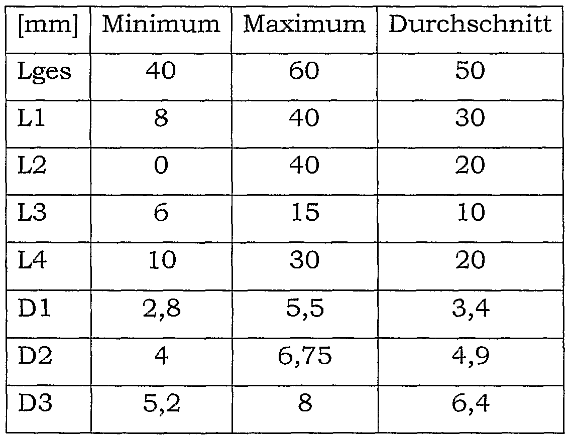
  • Lges axial length from belt axis 55 to screw tip 57
  • L1 axial length from ribbon axis 55 to toggle point 53
  • L3 axial length from ribbon axis 55 to bone entry 59
  • L4 axial length from bone entry 59 to toggle point 53
  • the dimensions to be used in a particular case depend, inter alia, on the technique used to position the pedicle screws.
  • the bending stiffness C measured in the direction of the longitudinal axis of the implanted fastening element can be defined as the product of the modulus of elasticity and second order moment of area (area moment of inertia).
  • the bending stiffness profile of the fastening element is particularly well suited to show the difference between conventional rigid pedicle screws on the one hand and the flexible fastening elements specified here on the other hand.
  • the bending stiffness of the fastener can be influenced by the choice of material for the shaft and the shaft geometry. In the first case, the modulus of elasticity is varied, whereas in the second case the momentum is changed.
  • Fig. 3 shows in the lower third of a fastener, which is provided in the form of a pedicle screw and a head 11 and a shaft 12 has.
  • the shaft 12 is provided with a relief zone 17 (zone II). Details of this relief zone 17 will not be discussed at this point. Concrete embodiments are explained below. Fig. 3 is still used to explain general relationships.
  • FIG. 3 shows the bending stiffness profile of the bone structure in which the pedicle screw is implanted, ie the bone structure of pedicle 13 and vertebral body 15.
  • the flexural stiffness profiles shown are measured long of the central axis of the shaft 12 of the fastener, which coincides at least approximately with the central axis of the pedicle 13.
  • FIG. 3 The illustration of FIG. 3 is divided into three zones along the shaft 12.
  • the shaft region between the head 11 and the beginning of the relief zone 17 is also referred to as the upper shaft region 19 (zone I), while the region of the shaft 12 located behind the relief zone 17 as viewed from the head 11 also acts as the lower shaft region 21 (zone III ) referred to as.
  • Curve 1 shows the flexural stiffness profile of a conventional, assumed as ideal cylindrical rigid pedicle screw without relief zone.
  • the flexural rigidity C is constant over the entire shaft length.
  • Curve 2 shows the bending stiffness profile of a tapered conical pedicle screw or a pedicle screw with a conical core in the direction of the free shaft end.
  • the flexural rigidity steadily decreases in this case.
  • Curves 3, 3a, 3b and 3c show flexural stiffness profiles of fasteners each provided with a relief zone or region 17.
  • the relief zone 17 begins before the transition between the pedicle 13 and the vertebral body 15 and ends behind this transition within the vertebral body 15.
  • the bending stiffness profile in each case has a pot-like course with steep walls, ie the decrease or increase in the flexural rigidity occurs abruptly.
  • the transitions can be pronounced more or less stepped be.
  • the dotted curve shows an example in which the transitions are rounded off from the course shown by the solid line.
  • the curves 3a and 3b show flexural stiffness profiles respectively corresponding to the course of the curve 3 with the difference that the lower shaft region 21 (zone III) is provided with significantly reduced rigidity, but still significantly above that in the relief zone 17 (zone II) is located.
  • the flexural rigidity in the lower shaft portion 21 corresponds to that in the relief zone 17.
  • the relief zone 17 extends to the tip at the free end of the fastener.
  • the upper third of FIG. 3 further shows that the bending stiffness CF in the relief zone 17 (zone II) is only about one-tenth of the corresponding value CS in the upper shaft region 19 (zone I).
  • curve 7 shows the axial course of the modulus of elasticity of the bone structure from pedicle 13 and vertebral body 15.
  • the corresponding course of the second-order surface moment of the bone is shown in curve 8.
  • the sum of the two curves 7 and 8, which represents the profile of the bending stiffness C of the bone structure of pedicle 13 and vertebral body 15 in this simplified model, is shown by a solid line as curve 6.
  • the relief zone 17 can be positioned in the shaft 12 in such a way that with implanted fastener corresponding to the lower third of FIG. 3, the transition between pedicle 13 and vertebral body 15 and thus the range of maximum bending Stiffness of the vortex within the relief zone 17 of the shaft 12 and in particular - as seen in the axial direction - is located centrally in the relief zone 17.
  • the axial length of the zone I and thus about the distance from the lower side of the head 11 to the beginning of the relief zone 17 can be between 8 mm and 35 mm.
  • the smallest length can be used for the vertebra L5 when the screw is screwed in so far that the screw head 11 rests against the bone.
  • the greatest length is used when working with a so-called posterior medial screw placement technique, with the system positioned posterior to the facet joints.
  • the length of the zone II ie the relief zone or flexible transition zone 17 a range of 0 mm to 35 mm may be provided.
  • the smallest length may be present when the relief zone 17 is designed as a joint (cf., the following exemplary embodiment in FIG. In this case, the relief zone 17 is formed practically from the rotation axis of the joint.
  • the greatest length may be present when the Relief zone 17 extends to the top of the fastener.
  • a range of 0 mm to 35 mm may be provided. The smallest length is given when no lower shaft portion 21 is provided in the sense of Fig. 3, but extends the relief zone 17 to the tip of the relief element. The greatest length may be present when the free end of the fastener touches or even punctures the anterior cortex (so-called bicortical screw insertion technique).
  • the relief zone 17 is formed by material removal on the shaft. Consequently, the relief zone 17 here is a shank region 27 with a reduced cross-sectional area compared to the adjacent shank regions 19, 21.
  • the cross section in the relief zone 17 is not circular, but the shaft portion 27 is formed like a leaf spring and provided in the form of a thin strip. The width of the strip corresponds to the original shaft diameter, whereas the strip thickness is substantially smaller than the original shaft diameter.
  • the bending stiffness profile of the shaft is thus rotationally asymmetric with respect to its longitudinal axis.
  • the orientation of the relief zone 17 is selected such that the plane defined by the strip 27 extends parallel to the flat support surfaces 45 on the screw head 11.
  • the relief zone 17 is therefore fully effective only in one plane, this plane is spanned by the longitudinal axis of the shaft and a normal of the flat support surfaces 45.
  • a first rough sizing of a screw according to FIG. 4 has shown the following:
  • the fatigue limit criterion dynamic load capacity or bending fatigue strength under maximum deformation of 10 °
  • Width 6.5 mm
  • This calculation example - which therefore does not lead to an optimal fastening element, but is nevertheless suitable for explaining the basic principle of the pedicle screw specified here - thus shows that the relief zone on the one hand determines the load capacity of the fastener and on the other hand, the load on the vertebral body: On the one hand, the bending stiffness in be reduced to the extent that the load capacity of the vertebral body is not exceeded, because the more resistant the relief zone is executed, the larger forces or moments can be transmitted to the vertebral body, which is basically desirable, because the free end of the fastener should contribute maximum, just without overloading the vertebral body (and so cause a relaxation).
  • the aim is to achieve the highest possible flexural rigidity in the relief zone.
  • the load capacity of the fastening element is reached earlier.
  • the fastener is thus designed so that there is an optimal "compromise" between these two basically opposing optimization criteria.
  • the shaft region forming the relief zone 17 is not made in one piece, but is formed by a separate intermediate piece 33 which is anchored in the upper and lower shaft regions 19, 21.
  • the intermediate piece 33 can be a rod made of a material of particularly low bending stiffness ("super-elastic" material). In particular, it is a material that can be deformed up to 10% or more without permanent deformation, which is not achieved by the usual implant steels or titanium.
  • a memory metal NiTi-based eg Nitinol
  • the elastic modulus of the shank can be selectively changed by changing the material in the relief zone 17.
  • FIG. 6 Another example of such a reduction of the modulus of elasticity by material change is shown in FIG. 6. Unlike the example in the lower illustration in FIG. 5, no cross-section reduction takes place here, but only a material change.
  • the intermediate piece 33 As a material for the pedicle screw specified here, and thus for the lower and upper shaft regions 19, 21 and the screw head 11, in particular a biocompatible titanium or steel alloy is used.
  • a material for the relief zone 17 forming separate intermediate piece 33 a material is used which has a significantly lower modulus of elasticity than the shaft material and thus provides for a corresponding flexibility or flexibility of the shaft.
  • One possible material for the intermediate piece 33 is plastic, in particular an elastomer.
  • the plastic can be fiber reinforced.
  • the intermediate piece 33 conically shaped in accordance with the shank profile is provided with anchoring extensions 34 extending on both sides in the axial direction, via which the intermediate piece 33 is fastened to the adjacent shank areas 19, 21.
  • Fig. 7 shows a variant in which also an example made of plastic material intermediate piece 33 is provided to form the relief zone 17.
  • the anchoring to the adjoining shank regions 19, 21 takes place by means of axial extensions 19a, 21a, which are formed integrally on these shank sections 19, 21 and are provided with radial widenings to improve the positive connection.
  • a special feature of this variant is that the extensions 19a, 21a approximately in the middle of the relief zone 17 within the intermediate piece 33 cooperate like a hinge, in the example shown here according to the ball / shell principle, where, for example, a hinge assembly may be provided.
  • the upper shaft portion 19 and the lower shaft portion 21 are thus connected in this example by a hinge 35 which is surrounded by the elastic material of the intermediate piece 33, whereby in the case of a deflection of the shaft for the corresponding restoring forces is provided.
  • the relief region 17 forming hinge region can in particular with the. Be molded intermediate piece 33 forming material.
  • FIGS. 8, 9 and 10 show embodiments in which, in turn, the surface moment is reduced and at the same time the shank material is optimally utilized.
  • the shaft is provided with a central bore 25. This is advantageous in terms of manufacturing technology and also makes it possible to implant the pedicle screws with the aid of a Kirschner wire, which is advantageous in particular in the case of percutaneous implantation.
  • the thread 31 of the screw is designed to be continuous.
  • the wall of the shaft is broken in the threaded valley.
  • the shaft is in the region of the relief zone 17 in the manner of a
  • Coil spring or a corkscrew trained Such a relief zone can easily be manufactured, for example, by wire erosion or by a driven side milling cutter.
  • the circumferential in the relief zone in the threaded valley slot can have a significantly smaller slot width than shown in Fig. 8.
  • the slot width can be selected to be so small that at a certain deflection of the shaft, the turns in the relief zone abut each other or rest, so that thereby pressure forces can be transmitted.
  • the slot formed according to FIG. 8 only in the relief zone 17 extends as far as the screw tip, ie, the entire remaining shaft is formed following the upper shaft region 19 in the manner of a helical spring or a corkscrew.
  • the slots can be filled with a bioresorbable material that reduces or eliminates the spring effect.
  • the intraoperative stability of the shaft can be increased.
  • the absorption takes place comparatively quickly or within a few days. Subsequent to the absorption, the flexibility of the screw predetermined by the shaft geometry is then fully effective.
  • the slot formed in the shank wall is designed in the same direction as the thread 31, according to the example of FIG. 9, the slot can also be formed opposite to the thread 31.
  • the effective frictional forces constrict the shaft or core diameter in the area of the relief zone 17. Springback of the shaft after elimination of the screwing force causes further compression of the surrounding bone material, which significantly improves the primary stability of the screw can.
  • a continuous central bore as in the example of Fig. 8, is not mandatory.
  • a central bore 25 extending only partially through the shaft can also be provided.
  • the bore 25 ends in the region of the lower shaft portion 21.
  • Fig. 10 shows, it is also possible for shafts without central bore, spiral or helical circumferential recesses provided to form the relief zone 17. By means of a suitably selected penetration depth, a helix can also be formed in this case. de structures are made, thus making a central hole superfluous.
  • the orientation of the depressions or slots can be selected in accordance with the examples of FIGS. 8 and 9 either in the same or in opposite directions with respect to the screw thread 31.
  • FIG. 11 comprises a number of special features, which are explained below, wherein such a combination of features is not mandatory, but the individual aspects can also be implemented independently of one another in conjunction with other configurations.
  • fastener of FIG. 11 is not a screw, but a pin-like fastener that is not screwed, but is taken in the vortex.
  • the shaft is provided with staggered slots 41 of small width, each opening into a through bore 39. Due to the small slot width, the impact pulses required for driving can be easily transmitted in the axial direction.
  • the cross-section of the shank may deviate from a circular shape and be designed in particular oval or elliptical in order to achieve a better adaptation to the natural pedicle shape, as has already been explained in the introduction.
  • shank of the fastening pin to be hammered can be provided with a thread present in the neck in order to be used in the case a re-operation to facilitate the explantation of the fastener.
  • screws provided with a slot-shaped or groove-shaped helical or spiral-shaped recess can also have a shank with a cross-section which deviates from a circular shape, ie. non-rotationally symmetric shaft geometries are not limited to impact pins according to FIG. 11.
  • Fig. 12 shows an example with staggered relief slots or notches 43, the width of each of which is greater than that of the slots 41 in the example of Fig. 11.
  • Such relief notches may be provided on both circular and circular cross-section shafts be.
  • a rotary joint 37 may be provided between the upper shaft section 19 and the lower shaft section 21.
  • a hinge pin defining the axis of rotation 38 of the joint 37 extends parallel to the planar support surfaces 45 of the screw head 11.
  • the position of the joint 37 along the shaft axis can be placed so that the axis of rotation of the joint 37 at implanted screw in the range of the aforementioned toggle point ( Fig. 3) and in particular runs through the toggle point.
  • the relief zone such that its flexural rigidity increases over time.
  • a plastic material can be used for the relief zone, the hardness of which increases over time, whereby the force or torque transmission increases correspondingly to the free end region of the fastener. This can take into account the fact that after a certain time at the end of the operation can be assumed that the fastener is well grown into the bone material. The initially still relatively high
  • Flexibility of the shaft thus serves in particular the purpose of avoiding high loads shortly after the operation.
  • the shaft can be designed in such a way that the flexural rigidity in the relief zone decreases over time.
  • absorbable components may be provided which have a stiffening effect during implantation and are absorbed over time, which gradually increases the flexibility of the shaft in the relief zone.
  • 14 shows a pedicle screw whose shaft 12 has a slot 65 penetrating the shaft 12 and extending in the longitudinal direction of the shaft 12 in order to form the relief zone 17.
  • FIG. 15 shows, using the example of the pedicle screw of FIG. 14, that the upper shaft region 19 can have longitudinally extending recesses 66 on the surface into which the bone can grow, thereby providing an anti-twist device.
  • Fig. 16 are shown purely schematically - several possible embodiments of the head 11 of a fastener of the type specified here, which differ as a connecting element 64 of an intervertebral stabilization system - for example, a belt 64 in the Dynesys system of the Applicant (see also following description of Fig. 17) - can be recorded in or on the head 11.
  • the head 11 While in the upper embodiment of the head 11 is formed as a ring or eyelet through which the connecting element 64 is passed, in the other embodiments, the head 11 in the manner of - with respect to the longitudinal axis of the fastener - upright, inclined or executed on the side "U", so that the connecting element 64 does not need to be “threaded through” through an opening, but (in the direction of arrow) can be inserted, either from above (so-called “toploading” principle) or from the side (so-called “sideloading” principle). All of the exemplary embodiments described above with reference to FIGS. 3 to 15 of the pedicle screw specified here can in principle be provided with each of the head variants shown in FIG. 16. The "toploading" principle is described for example in EP 528 706.
  • FIG. 17 shows in several illustrations an example of an intervertebral stabilization system, which may include fastening elements specified here, in particular in the form of pedicle screws.
  • the dynamic system shown is an elastic support system (Applicant's Dynesys system), as previously mentioned several times.
  • Neighboring vortices are interconnected by two identical subsystems.
  • two pedicle screws each having a shaft 12 and a head 11 are implanted, each extending through a pedicle 13 into the vertebral body 15.
  • a compressible pressure or support body 63 is arranged in each case between two screw heads 11.
  • a in the implanted state to train biased and fixed by means of fixing screws 61 in the heads 11 band 64 extends through the pressure body 63 and the heads 11 therethrough. With the belt 64 tensile forces and the pressure body compressive forces are absorbed elastically.
  • the pedicle screws shown can be fasteners of the type specified here. LIST OF REFERENCE NUMBERS

Abstract

The invention relates to a pedicle screw comprising a head (11) for coupling to an elastic intervertebral stabilizing or supporting system and comprising a shank, which is to be anchored inside a vertebra and which, when implanted, extends through the pedicle and into the vertebral body. The shank comprises, in its longitudinal extension measured from the head: an upper shank area (19) adjacent to the head and a stress-relief area (17), which is joined to the upper shank area, the stress-relive area having a flexural strength less than that of the upper shank area, and the stress-relief area is placed in the area of the shank provided for being placed inside the bone.

Description

Pedikelschrau.be Pedikelschrau.be
Die Erfindung betrifft eine Pedikelschraube, umfassend einen Kopf zur Koppelung mit einem elastischen intervertebralen Stabilisierungs- oder Stützsystem, und einen zur Verankerung in einem Wirbel dienenden Schaft, der sich im implantierten Zustand durch den Pedikel hindurch in den Wirbelkörper erstreckt. Die Erfindung betrifft außerdem ein interver- tebrales Stabilisierungssystem mit mehreren Pedikelschrauben.The invention relates to a pedicle screw comprising a head for coupling with an elastic intervertebral stabilization or support system, and a shaft for anchoring in a vertebra, which extends in the implanted state through the pedicle into the vertebral body. The invention also relates to an intervertebral stabilization system with a plurality of pedicle screws.
Die Pedikelschrauben werden nachstehend auch als "Befestigungselemente" bezeichnet.The pedicle screws are also referred to below as "fasteners".
Pedikelschrauben dieser Art und intervertebrale Stabilisierungs- und Stützsysteme sind beispielsweise aus US 2005/0154390, US 5,492,442, WO2005/065374, WO03/032862, EP 0 669 109, EP 0 672 388, US 4,950,269 oder EP 528 706 bekannt. Derartige Schrauben weisen als Kopf eine geschlossene oder einseitig geöffnete Öse auf, wobei letztere Form in bestimmten Ausführungsformen Tulpen- oder Stimmgabelform aufweist und die Öse vorgesehen ist, um die intervertebralen Stabilisierungs- oder Stützelemente aufzunehmen und durch geeignete Maßnahmen zu fixieren.Pedicle screws of this type and intervertebral stabilization and support systems are known, for example, from US 2005/0154390, US Pat. No. 5,492,442, WO2005 / 065374, WO03 / 032862, EP 0 669 109, EP 0 672 388, US Pat. No. 4,950,269 or EP 528,706. Such screws have as a head a closed or unilaterally open eyelet, the latter form in certain embodiments tulip or tuning fork shape and the eyelet is provided to receive the intervertebral stabilization or support elements and to fix by suitable measures.
Ein Pedikel, in den eine Schraube eingebracht werden soll, kann in einem vereinfachten mechanischen Modell als ein am Wirbelkörper befestigter Balken betrachtet werden, der sich bei Belastung signifikant durchbiegen kann. Dabei ist das Steifigkeitsprofil in Richtung der Längsachse des Pedikels nicht konstant. Vielmehr ist die Steifigkeit im Bereich des Über- gangs zwischen Pedikel und Wirbelkörper im Vergleich zu den angrenzenden Bereichen deutlich erhöht. Dabei haben Untersuchungen ergeben, dass sich bei implantierten starren Pedikelschrauben, wie sie herkömmlicherweise verwendet werden, der Pedikel einschließlich der Schraube durchbiegt, wenn eine kaudal-kraniale Kraft am Schraubenkopf angreift. Aufgrund der deutlich höheren Biegesteifigkeit der Schraube bildet sich ein auch als Togglepoint bezeichneter Drehpunkt aus, um den die Pedi- kelschraube unter Belastung kippt. Dieser Drehpunkt liegt im Allgemeinen in etwa mehr oder weniger im Bereich des Übergangs zwischen Pedi- kel und Wirbelkörper. Das Verkippen der belasteten Pedikelschraube führt zu einer hohen Belastung der Spongiosa des Wirbelkörpers durch den freien Endbereich und insbesondere durch die Spitze der Pedikelschraube. Hierdurch kommt es zu starken Belastungen des so genannten Knocheninterface, was unter ungünstigen Umständen, beispielsweise bei fort- schreitender Osteoporose, auf lange Sicht in Schraubenlockerungen resultieren kann. Außerdem werden hohe Spannungen innerhalb des Schaftes vor allem leicht anterior des Drehpunktes erzeugt.A pedicle into which a screw is to be inserted can, in a simplified mechanical model, be regarded as a beam attached to the vertebral body, which can sag significantly under load. The stiffness profile in the direction of the longitudinal axis of the pedicle is not constant. Rather, the stiffness in the region of the over- Gangs between pedicle and vertebral body compared to the adjacent areas significantly increased. Studies have shown that when implanted rigid pedicle screws, as they are commonly used, the pedicle including the screw sags when a caudal-cranial force acts on the screw head. Due to the significantly higher flexural rigidity of the screw, a pivot point, also referred to as a toggle point, forms around which the pedicle screw tilts under load. This fulcrum is generally more or less in the area of the transition between the pedicle and the vertebral body. The tilting of the loaded pedicle screw leads to a high load on the cancellous bone of the vertebral body through the free end region and in particular through the tip of the pedicle screw. This leads to heavy loads on the so-called bone interface, which under unfavorable circumstances, for example in the case of progressive osteoporosis, can in the long run result in screw loosening. In addition, high stresses within the shaft are generated, above all, slightly anterior to the pivot point.
Pedikelschrauben werden sowohl in Verbindung mit starren als auch elas- tischen intervertebralen Stabilisierungs- oder Fixationssystemen (Verstei- fungs- oder Stützsystemen) eingesetzt. Bei Systemen, welche eine nicht winkelstabile Verbindung oder Koppelung zwischen den intervertebralen Stützelementen, zum Beispiel zwischen einer an einem kaudalen und einer an einem kranialen Wirbel befestigten Pedikelschraube angeordne- ten Stäben oder Bändern, einerseits und den Pedikelschrauben andererseits vorsehen, wie beispielsweise elastischen, dynamisch stabilisierenden Systemen, werden im Wesentlichen keine Momente, sondern praktisch ausschließlich reine Zug- /Druckkräfte in den Schraubenkopf eingeleitet beziehungsweise dort aufgenommen. Dies hat zur Folge, dass der Pedikel sich durchbiegen kann. Die steife Schaube erfährt also eine Art Kippbeanspruchung, welche aufgrund der vergleichsweise geringen Biegesteifigkeit der Pedikel von diesen nicht abgestützt werden kann und daher im Be- reich der Schraubenspitze am so genannten Knocheninterface hohe Kräfte in die Spongiosa des Wirbelkörpers einbringt.Pedicle screws are used in conjunction with both rigid and elastic intervertebral stabilization or fixation systems (stiffening or support systems). In systems which provide a non-angularly stable connection or coupling between the intervertebral support elements, for example between a pedicle screw attached to a caudal pedicle screw and a cranial vertebra, on the one hand and the pedicle screws on the other, such as elastic, dynamically stabilizing Systems are introduced essentially no moments, but almost exclusively pure tensile / compressive forces in the screw head or recorded there. This has the consequence that the pedicle can bend. The stiff screw thus experiences a kind of tilting stress, which due to the comparatively low bending stiffness of the pedicles can not be supported by these and therefore introduces high forces into the cancellous bone of the vertebral body in the area of the screw tip on the so-called bone interface.
Dieses Phänomen tritt im Übrigen bei Versteifungssystemen, welche eine winkelinvariante Kopplung beinhalten, in weitaus geringerem Maße auf als bei Systemen mit Winkelvarianten Systemen: Aufgrund der Winkelin- variabilität wird eine Kippbelastung der Schraube verunmöglicht, d. h. das Moment, das bei einem winkelvarianten System die Kraft an der Schraubenspitze über den Hebelarm vom Togglepoint zur Schraubenspitze induziert, wird bei einem winkelinvarianten System direkt im Schaubenkopf ausgeglichen, wobei die nachfolgend angegebene und beanspruchte Pedi- kelschraube ohne weiteres auch für diese winkelinvarianten Systeme geeignet ist.Incidentally, this phenomenon occurs to a much lesser extent in stiffening systems which include an angle-invariant coupling than in systems with angular variant systems: Due to the angular inversion, a tilting load on the screw is rendered impossible; H. The moment that induces the force at the screw tip via the lever arm from the toggle point to the screw tip in an angle-variant system is compensated directly in the screw head with an angle-invariant system, whereby the pedicle screw indicated below and claimed is also suitable for these angle-invariant systems ,
Aus der US 2005/ 154390 ist eine Pedikelschraube bekannt, welche in einem mehr oder weniger unmittelbar am Kopf angrenzenden und nach der Implantation außerhalb des Knochens liegenden Bereich eine biegeelastische Zone aufweist.A pedicle screw is known from US 2005/154390, which has a flexurally elastic zone in a region which adjoins the bone more or less directly at the head and lies outside the bone after implantation.
Es soll eine Pedikelschraube der eingangs genannten Art angegeben wer- den, welche neben anderen vorteilhaften Eigenschaften auch in der Lage ist, eine Lockerung der Schrauben zu vermeiden und gleichzeitig eine geeignete Abstützung von Momenten, welche durch den Angriff von Kräften am Schraubenkopf entstehen, zu gewährleisten. Die in Anspruch 1 angegebene Pedikelschraube vermag, neben einer Vielzahl weiterer vorteilhafter Eigenschaften, diese Forderung zu erfüllen.A pedicle screw of the type mentioned in the introduction is to be specified which, in addition to other advantageous properties, is also able to prevent loosening of the screws and at the same time to ensure suitable support of moments which arise as a result of the application of forces to the screw head , The specified in claim 1 pedicle screw is capable, in addition to a variety of other advantageous properties to meet this requirement.
Die Pedikelschraube eignet sich unter anderem zur Verwendung in inter- vertebralen Versteifungs- oder Stützsystemen, welche eine nicht winkelstabile Verbindung zwischen den intervertebralen Stützelementen, zum Beispiel zwischen einer an einem kaudalen und einer an einem kranialen Wirbel befestigten Pedikelschraube angeordneten Stäben oder Bändern, und den Pedikelschrauben vorsehen. Ein System dieser Art wird ebenfalls angegeben und beansprucht. Selbstverständlich kann die hier angegebene Schraube auch in anderen Stütz- oder Versteifungs Systemen oder sonstigen Anwendungen höchst vorteilhafte Wirkungen entfalten.The pedicle screw is suitable, inter alia, for use in intervertebral stiffening or support systems which provide a non-locking connection between the intervertebral support elements, for example, between a pedicle screw attached to a caudal and pedicle screw attached to a cranial vertebra, and the pedicle screws provide. A system of this kind is also indicated and claimed. Of course, the screw specified here can also develop highly advantageous effects in other support or stiffening systems or other applications.
Bei der hier angegebenen Pedikelschraube ist der Schaft mit einer Entlastungszone versehen, die eine reduzierte Biegesteifigkeit gegenüber einem in Richtung des Kopfes angrenzenden oberen Schaftbereich aufweist, wobei die Entlastungszone im zur Anordnung im Knochen vorgesehenen Bereich des Schaftes gelegen ist.In the pedicle screw disclosed herein, the stem is provided with a relief zone having a reduced flexural rigidity against an upper stem region adjacent the head, the relief zone being located in the region of the stem for placement in the bone.
Der Schaft des Befestigungselementes (Pedikelschraube) ist mit einer Entlastungszone versehen, die auch als flexible Übergangszone bezeichnet werden kann. Dies bedeutet eine Abkehr von herkömmlichen Pedikelschrauben, die über ihre gesamte Länge starr ausgebildet sind und eine im Vergleich zum Knochenmaterial der Wirbel hohe Biegesteifigkeit aufweisen. Durch die Entlastungszone erhält der Schaft des Befestigungselementes ein Biegesteifigkeitsprofü, dessen Verlauf durch die Ausgestaltung der Entlastungszone prinzipiell beliebig eingestellt und insbesondere an die charakteristischen Eigenschaften des Wirbels angepasst werden kann. Es hat sich herausgestellt, dass durch die Entlastungszone die Übertragung von Biegemomenten, die durch am Kopf des Befestigungselementes angreifende Kräften verursacht werden, in den freien Endbereich des Befestigungselementes begrenzt werden kann. Der Schaft des Befestigungselementes kann sich unter Last aufgrund der Entlastungszone gewisserma- ßen im Gleichklang mit der Knochenstruktur, in die das Befestigungselement implantiert ist, durchbiegen. Hohe Belastungen des Knochenmaterials und hohe Spannungen im Schaft werden hierdurch vermieden. Die Anpassung der Biegesteifigkeit der Pedikelschraube an die biologischen Gegebenheiten schafft damit eine weiter verbesserte Sicherheit für den Patienten.The shaft of the fastener (pedicle screw) is provided with a relief zone, which can also be referred to as a flexible transition zone. This means a departure from conventional pedicle screws, which are rigid over their entire length and have a high compared to the bone material of the vertebrae flexural rigidity. Due to the relief zone, the shank of the fastening element is given a bending stiffness profile, the course of which can in principle be arbitrarily set by the design of the relief zone and, in particular, adapted to the characteristic properties of the vertebra. It has been found that by the relief zone, the transmission of bending moments, which are caused by acting on the head of the fastener forces can be limited in the free end region of the fastener. The shank of the fastener may, under load due to the relief zone, somehow bend in unison with the bone structure into which the fastener is implanted. High loads on the bone material and high stresses in the shaft are thereby avoided. The adaptation of the bending stiffness of the pedicle screw to the biological conditions thus creates a further improved safety for the patient.
Bei dem weiterhin angegebenen und beanspruchten intervertebralen Stabilisierungssystem sind eine Mehrzahl von an den Wirbeln verankerbaren Pedikelschrauben und eine Verbindungseinrichtung zum Verbinden von zumindest zwei an benachbarten Wirbeln verankerten Pedikelschrauben zu einem elastischen Versteifungs- oder Stützsystem vorgesehen.In the further specified and claimed intervertebral stabilization system, a plurality of pedicle screws anchorable to the vertebrae and a connecting device for connecting at least two pedicle screws anchored to adjacent vertebrae to an elastic stiffening or support system are provided.
Herkömmliche Pedikelschrauben besitzen häufig eine konische Form und damit streng genommen keine über die Schaftlänge konstante Biegestei- figkeit. Ein solches "Biegesteifigkeitsprofü" besitzt aber gerade keine Entlastungszone in dem hier angegebenen Sinne. Die hier angegebene Pedikelschraube basiert vielmehr auf dem Gedanken, die Biegesteifigkeit des Schaftes in einem bestimmten axialen Bereich gezielt herabzusetzen. Pedikelschrauben werden üblicherweise im Bereich der Lendenwirbel Ll bis L5 implantiert. Obwohl diese Wirbel weder bei demselben Patienten noch bei unterschiedlichen Patienten identisch ausgebildet sind, stimmen alle für die Implantation von Pedikelschrauben in Frage kommenden Wirbel hinsichtlich bestimmter Charakteristiken überein, wie vorstehend bereits erwähnt. Dieser Umstand, auf den nachstehend näher eingegangen wird, kann bei der hier angegebenen Pedikelschraube genutzt werden, indem das Biegesteifigkeitsprofil des Schaftes gezielt an die von Pedikel und Wirbelkörper gebildete Knochenstruktur angepasst wird. Die hier angegebene Pedikelschraube ist aber nicht auf die genannten Lendenwirbel beschränkt. Insbesondere ist grundsätzlich auch eine Anwendung für die thorokalen Wirbel möglich.Conventional pedicle screws often have a conical shape and, strictly speaking, no constant flexural rigidity over the length of the shaft. But such a "Biegesteifigkeitsprofü" has just no relief zone in the sense given here. Rather, the pedicle screw specified here is based on the idea of deliberately reducing the bending stiffness of the shaft in a specific axial region. Pedicle screws are usually implanted in the area of the lumbar vertebra L1 to L5. Although these vertebrae are not identical in the same patient or in different patients, all vertebrae of interest for the implantation of pedicle screws are consistent with certain characteristics, as mentioned above. This circumstance, which will be discussed in more detail below, can be used in the pedicle screw specified here by the bending stiffness profile of the shaft is specifically adapted to the bone structure formed by pedicle and vertebral body. However, the pedicle screw specified here is not limited to the lumbar vertebrae mentioned. In particular, an application for the thoracic vertebrae is possible in principle.
Weitere Ausführungsformen sind auch in den abhängigen Ansprüchen, der Beschreibung sowie der Zeichnung angegeben, wobei die Merkmale dieser Ausführungsformen in an sich beliebiger Weise miteinander kombinierbar sind.Further embodiments are also specified in the dependent claims, the description and the drawing, wherein the features of these embodiments can be combined with each other in any desired manner.
In einer Ausführungsform ist die Biege Steifigkeit der Entlastungszone im Wesentlichen der eines Pedikels angepasst oder liegt leicht darüber. Die Biegesteifigkeit beträgt beispielsweise das 1,5- bis 4-fache, das 1,5- bis 3- fache, das 2- bis 4-fache oder das 2- bis 3-fache der Biegesteifigkeit der Pedikel, wobei dieser Wert abhängig von der gesamten Geometrie der Schraube so zu wählen ist, dass insbesondere im Bereich der Schraubenspitze sich eine Flächenpressung des Spongiosagewebes einstellt, die unter der maximal zulässigen Flächenpressung liegt, dabei aber unter Be- rücksichtigung eines Sicherheitsfaktors eine möglichst gute Ausnutzung der zulässigen Belastung erlaubt.In one embodiment, the bend stiffness of the relief zone is substantially equal to or slightly above that of a pedicle. The bending stiffness is, for example, 1.5 to 4 times, 1.5 to 3 times, 2 to 4 times or 2 to 3 times the bending stiffness of the pedicles, this value depending on the The entire geometry of the screw is to be selected such that, in particular in the region of the screw tip, a surface pressure of the cancellous bone tissue is set that is below the maximum permissible surface pressure, but in so doing consideration of a safety factor allows the best possible use of the permissible load.
Der Kopf kann mit dem oberen Schaftbereich wenigstens in Biegerichtung des Schaftes starr gekoppelt und insbesondere einteilig sein. Im Falle einer nicht einteiligen Ausführung ist es dabei möglich, aber nicht zwingend, dass die Koppelung zwar bezüglich einer Biegung fest, eine Torsion dagegen aber möglich ist.The head can be rigidly coupled to the upper shaft region at least in the bending direction of the shaft and in particular be in one piece. In the case of a non-one-piece design, it is possible, but not mandatory, that the coupling is fixed with respect to a bend, but torsion is possible.
Der Gradient der Biege Steifigkeit am Übergang vom oberen Schaftbereich zur Entlastungszone kann betragsmäßig größer, insbesondere signifikant größer, sein als ein im oberen Schaftbereich auftretender Biegesteifigkeits- gradient.The gradient of the bending stiffness at the transition from the upper shaft region to the relief zone can be greater in magnitude, in particular significantly greater, than a bending stiffness gradient occurring in the upper shaft region.
Am Übergang vom oberen Schaftbereich zur Entlastungszone kann wenigstens in einem Bereich des Schaftes der Betrag des Gradienten der Biegesteifigkeit wenigstens doppelt so groß, insbesondere wenigstens 5mal so groß, und weiterhin insbesondere wenigstens lOmal so groß sein wie im oberen Schaftbereich.At the transition from the upper shaft region to the relief zone, the amount of the gradient of bending stiffness may be at least twice as large, in particular at least 5 times as great, and furthermore in particular at least 10 times as great as in the upper shaft region, at least in one region of the shaft.
Die Biegesteifigkeit kann am Übergang im Wesentlichen sprunghaft reduziert sein.The bending stiffness can be substantially reduced abruptly at the transition.
Die Biegesteifigkeit in der Entlastungszone kann in wenigstens einer Biegeebene gegenüber der Biegesteifigkeit im oberen Schaftbereich um wenigstens 30%, insbesondere um wenigstens 50%, in einer weiteren Ausführungsform um wenigstens 60%, und in einer noch weiteren Ausführungsform um wenigstens 80% geringer sein. Der obere Schaftbereich kann derart dimensioniert sein, dass die Entlastungszone im zur Anordnung in der Spongiosa vorgesehenen Bereich des Schaftes gelegen ist, während wenigstens der zur Anordnung in der Korti- kalis vorgesehene Bereich von dem oberen Schaftbereich gebildet ist. Der obere Schaftbereich dient somit zur Abstützung am festen Knochenmaterial.The flexural rigidity in the relief zone may be at least 30% lower in at least one bending plane than the bending stiffness in the upper shaft region, in particular at least 50%, in another embodiment at least 60%, and in yet another embodiment at least 80% lower. The upper shaft region may be dimensioned such that the relief zone is located in the area of the shaft which is intended to be arranged in the cancellous bone, while at least the region provided for arrangement in the corticalis is formed by the upper shaft region. The upper shaft region thus serves to support the solid bone material.
Die Länge des oberen Schaftbereiches kann im Minimum 5mm, insbeson- dere im Minimum 8mm sowie im Maximum 15mm, und insbesondere im Maximum 12mm betragen.The length of the upper shaft area may be at least 5 mm, in particular at least 8 mm and at the maximum 15 mm, and in particular at the maximum 12 mm.
Wie vorstehend bereits angedeutet, besitzt die Biegesteifigkeit bzw. die maximal zulässige Flächenpressung im Wirbel einen für alle Wirbel prin- zipiell gleichen charakteristischen Verlauf, bezogen auf eine durch den Pedikel und den Wirbelkörper verlaufende Achse, die mit der Mittelachse des Befestigungselementes im implantierten Zustand zusammenfällt.As already indicated above, the bending stiffness or the maximum permissible surface pressure in the vertebra has a characteristic course that is basically the same for all vertebrae, with respect to an axis running through the pedicle and the vertebral body, which coincides with the central axis of the fastening element in the implanted state.
Dieser Umstand kann ausgenutzt werden, indem ein axiales Biegesteifig- keitsprofil des Schaftes wenigstens an den qualitativen Verlauf der Biegesteifigkeit des Pedikels angenähert ist und diesem im Idealfall entspricht. Hierdurch kann erreicht werden, dass die von der Pedikelschraube ausgeübte, senkrecht zu ihrer Längserstreckung verlaufende Querkraft entlang ihrer Längserstreckung zumindest näherungsweise konstant ist.This fact can be exploited by approximating an axial bending stiffness profile of the shank to at least the qualitative course of the flexural rigidity of the pedicle and, in the ideal case, corresponding to this. In this way, it can be achieved that the transverse force exerted by the pedicle screw and perpendicular to its longitudinal extent is at least approximately constant along its longitudinal extension.
Die Entlastungszone kann zwischen dem oberen Schaftbereich und einem unteren Schaftbereich gelegen sein, die beide eine höhere Biegesteifigkeit aufweisen als die Entlastungszone. Am Übergang von der Entlastungszone zum unteren Schaftbereich kann wenigstens in einem Bereich des Schaftes der Betrag des Gradienten der Biegesteifigkeit wenigstens doppelt so groß, insbesondere wenigstens 5mal so groß, und weiterhin insbesondere wenigstens lOmal so groß sein wie im unteren Schaftbereich.The relief zone may be located between the upper shaft region and a lower shaft region, both of which have a higher flexural rigidity than the relief zone. At the transition from the relief zone to the lower shaft region, the amount of the gradient of the bending stiffness may be at least twice as large, in particular at least 5 times as great, and furthermore in particular at least 10 times as great as in the lower shaft region, at least in one region of the shaft.
Bei dieser Ausgestaltung ist also auch der - vom Kopf aus gesehen - hinter der Entlastungszone gelegene untere Schaftbereich biegesteifer als die Entlastungszone. Diese Ausgestaltung des Befestigungselementes ist aber nicht zwingend. Prinzipiell ist es vielmehr auch möglich, eine sich bis zum freien Ende des Befestigungselementes erstreckende Entlastungszone vorzusehen. Bei entsprechender Ausgestaltung insbesondere der Spitze des Befestigungselementes kann hierdurch ein "Führungseffekt" im Pedi- kel genutzt werden. Das Befestigungselement wird beim Einbringen gewissermaßen "automatisch" von der relativ harten kortikalen Außenschicht korrigierend abgelenkt; mit einer entsprechend ausgebildeten Pedikel- schraube könnte somit gewissermaßen "um die Ecke" geschraubt werden.In this embodiment, therefore, also the - viewed from the head - located behind the discharge zone lower shaft region is more rigid than the relief zone. This embodiment of the fastener is not mandatory. In principle, it is also possible to provide an extending to the free end of the fastener relief zone. With a suitable design, in particular the tip of the fastening element, a "guiding effect" in the pedicle can thereby be used. The fastener is deflected during introduction so to speak "automatically" correcting the relatively hard cortical outer layer; with a suitably designed pedicle screw could thus be screwed "around the corner".
Der Wechsel der Biegesteifigkeit von der Entlastungszone zum unteren Schaftbereich kann im Wesentlichen sprunghaft erfolgen.The change of the flexural rigidity from the relief zone to the lower shaft region can essentially occur abruptly.
Das Profil des Biegesteifigkeitsverlaufs zwischen dem oberen Schaftbereich und dem unteren Schaftbereich kann im Wesentlichen topf-, trog- oder wannenförmig ausgebildet sein.The profile of the flexural stiffness curve between the upper shaft region and the lower shaft region may be substantially pot-shaped, trough-shaped or trough-shaped.
Die Lage sowie die axiale Länge der Entlastungszone im Schaft sind auf die Lage der Übergangszone zwischen Pedikel und Wirbelkörper im Wirbel abgestimmt, für den das Befestigungselement konzipiert ist. Da die Knochenstruktur von Wirbeln hinreichend bekannt ist, steht hinreichend genau fest, an welcher Stelle längs des implantierten Schaftes die erwähnte Übergangszone sowie der vorstehend bereits erwähnte Togglepoint liegen. Dies gilt zumindest jeweils bezogen auf eine bestimmte, vom Operateur gewählte Setztechnik. So ist beispielsweise zu berücksichtigen, dass z.B. für eine so genannte bikortikale Verankerung vergleichsweise lange Pedikelschrauben zum Einsatz kommen. Vor diesem Hintergrund kann bei der hier angegebenen Pedikelschraube die Entlastungszone in einem mittleren Bereich der Längserstreckung des Schaftes gelegen sein, insbesondere im Wesentlichen in den beiden mittleren Vierteln des Schaftes oder im mittleren Drittel des Schaftes.The position as well as the axial length of the relief zone in the shaft are based on the position of the transition zone between pedicle and vertebral body in the vertebra matched, for which the fastener is designed. Since the bone structure of vertebrae is well known, it is sufficiently clear at which point along the implanted shaft the aforementioned transition zone and the above-mentioned toggle point are. This applies at least in each case based on a specific, selected by the surgeon setting technique. For example, it should be noted that comparatively long pedicle screws are used, for example, for so-called bicortical anchoring. Against this background, in the case of the pedicle screw specified here, the relief zone may be located in a middle region of the longitudinal extent of the shaft, in particular substantially in the two middle quarters of the shaft or in the middle third of the shaft.
Die Entlastungszone kann eine signifikante axiale Länge des Schaftes einnehmen. Wenn der Schaft mit einem Gewinde versehen ist, dann kann sich die Entlastungszone in Längsrichtung über eine Mehrzahl von Gewindegängen erstrecken.The relief zone may occupy a significant axial length of the shaft. If the stem is threaded, then the relief zone may extend longitudinally through a plurality of threads.
Der obere Schaftbereich und die Entlastungszone können derart dimensi- oniert sein, dass im implantierten Zustand sich die Entlastungszone im Bereich des Übergangs zwischen Pedikel und Wirbelkörper befindet und insbesondere sich auf beiden Seiten axial über den Übergangsbereich hinaus erstreckt, wobei in einer Ausführungsform vom Kopf aus gesehen ein hinter dem Übergang gelegener Abschnitt der Entlastungszone eine größere axiale Länge aufweist als ein vor dem Übergang gelegener Abschnitt der Entlastungszone. Der Schaft kann mit einem Gewinde versehen sein, wobei das Gewinde durch die Entlastungszone unterbrochen ist.The upper shaft region and the relief zone can be dimensioned such that, in the implanted state, the relief zone is in the area of the transition between pedicle and vertebral body and, in particular, extends axially beyond the transitional region on both sides, in one embodiment viewed from the head a portion of the relief zone located behind the transition has a greater axial length than a portion of the relief zone located before the transition. The shank may be threaded, with the thread being interrupted by the relief zone.
Der Schaft kann zumindest bereichsweise hohl ausgeführt und insbeson- dere mit einer zentralen Längsbohrung versehen sein.The shank can be hollow at least in some regions and, in particular, provided with a central longitudinal bore.
Die Längsbohrung kann durchgehend ausgeführt sein, wobei dies allerdings nicht zwingend ist. Eine durchgehende Bohrung hat unter anderem den Vorteil, dass das Befestigungselement bei der Implantation beispiels- weise mittels eines Kirschnerdrahtes geführt werden kann.The longitudinal bore may be continuous, but this is not mandatory. One of the advantages of a through bore is that the fastening element can be guided during implantation by means of a Kirschner wire, for example.
Eine hohle Ausgestaltung des Schaftes ist allerdings nicht zwingend. Der Schaft kann auch massiv ausgeführt sein, wobei eine massive Ausführung des Schaftes auch in der Entlastungszone vorgesehen sein kann.However, a hollow configuration of the shaft is not mandatory. The shaft can also be made solid, wherein a solid version of the shaft can also be provided in the relief zone.
Der Schaft kann zumindest in der Entlastungszone mit einer Querschnittsschwächung im Vergleich zum oberen Schaftbereich und insbesondere auch zu einem unteren Schaftbereich versehen sein.The shank can be provided with a cross-sectional weakening, at least in the relief zone, in comparison to the upper shank region and in particular also to a lower shank region.
Die reduzierte Biegesteifigkeit in der Entlastungszone des Schaftes kann dadurch realisiert werden, dass der Schaft in der Entlastungszone mit einer Schwächung durch Materialwegnahme versehen ist. Diese Materialwegnahme kann derart erfolgen, dass das Flächenmoment des Schaftes unter gleichzeitiger optimaler Ausnutzung des den Schaft bildenden Werk- Stoffes reduziert ist.The reduced bending stiffness in the relief zone of the shank can be realized by providing the shank in the relief zone with weakening due to material removal. This removal of material can take place in such a way that the moment of area of the shank is reduced with simultaneous optimum utilization of the material forming the shank.
Für die Schwächung durch Materialwegnahme gibt es zahlreiche in der Praxis realisierbare Möglichkeiten. Beispiele sind im Folgenden kurz skiz- ziert. Auf entsprechende konkrete Ausgestaltungen wird in Verbindung mit der Beschreibung der Zeichnungen näher eingegangen.For the weakening by material removal there are numerous possibilities that can be realized in practice. Examples are briefly sketched below. ed. Corresponding specific embodiments will be discussed in more detail in connection with the description of the drawings.
Die Entlastungszone kann von einem lang gestreckten Schaftbereich mit im Vergleich zum oberen Schaftbereich und insbesondere auch zu einem unteren Schaftbereich reduzierter Querschnittsfläche gebildet sein.The relief zone can be formed by an elongate shaft region with a reduced cross-sectional area compared to the upper shaft region and in particular also to a lower shaft region.
Der Schaft kann zumindest in der Entlastungszone als Wendel ausgebildet sein.The shaft may be formed as a helix, at least in the relief zone.
Der Schaft kann zumindest in der Entlastungszone mit wenigstens einer nut- oder schlitzartigen Vertiefung versehen sein, die insbesondere wendeiförmig umläuft. Die umlaufende Vertiefung kann gleichsinnig oder gegensinnig in Bezug auf ein am Schaft ausgebildetes Gewinde orientiert sein.The shaft can be provided, at least in the relief zone, with at least one groove-like or slot-like depression, which in particular revolves helically. The circumferential recess can be oriented in the same direction or in opposite directions with respect to a thread formed on the shaft.
Ist der Schaft zumindest bereichsweise hohl ausgeführt bzw. mit einer zentralen Längsbohrung versehen, kann vorgesehen sein, dass in den hohl ausgeführten Schaftbereichen die Wandung des Schaftes durchbro- chen ist.If the shaft is hollow at least in regions or provided with a central longitudinal bore, it can be provided that the wall of the shaft is perforated in the hollow shaft regions.
Handelt es sich um einen mit einem Gewinde versehenen Schaft, so kann die Wandung im Gewindetal durchbrochen sein. Möglich ist aber auch eine Ausführung, bei der die Wandung in der Gewindespitze unterbrochen ist.If it is a threaded shank, the wall can be broken in the threaded valley. But also possible is an embodiment in which the wall is interrupted in the thread crest.
Eine derartige Ausgestaltung des Schaftes eignet sich auch für solche Befestigungselemente, die nicht in den Wirbel eingedreht, sondern vielmehr eingeschlagen werden, da aufgrund der geringen Schlitzbreite die Einschlagimpulse problemlos in axialer Richtung übertragen werden können.Such a design of the shaft is also suitable for such fasteners that are not screwed into the vertebra, but rather be taken because due to the small slit width the impact pulses can be easily transferred in the axial direction.
Bei dem hier angegebenen Befestigungselement muss es sich nicht zwin- gend um Schrauben im herkömmlichen Sinne, sondern es kann sich auch um durch Einschlagen implantierbare Befestigungselemente handeln. Nichtsdestotrotz kann der Schaft eines solchen Einschlagelementes mit einem Gewindeansatz versehen sein, der das Einschlagen nicht behindert, ein Explantieren durch Herausdrehen aber erleichtert bzw. ermöglicht.The fastening element specified here does not necessarily have to be screws in the conventional sense, but may also be implantable fastening elements. Nevertheless, the shank of such an impact element can be provided with a threaded projection which does not hinder the impacting, but facilitates explantation by unscrewing.
Die Wandung des Schaftes kann wenigstens in der Entlastungszone zwei wendeiförmig umlaufende schlitzförmige Durchbrechungen aufweisen.The wall of the shaft may have at least in the relief zone two helically circumferential slot-shaped openings.
Der Schaft kann wenigstens im Bereich der Entlastungszone eine Doppel- wendel ausbilden.The shaft can form a double helix at least in the region of the relief zone.
Die Steigung der Wendel im Bereich der Entlastungszone kann wenigstens 5mm, insbesondere wenigstens 10 mm, betragen.The pitch of the helix in the region of the relief zone can be at least 5 mm, in particular at least 10 mm.
Die Steigung der Wendel kann über die Längserstreckung des Schaftes variieren, wodurch die Biegesteifigkeit des Schaftes über die Längserstreckung variiert.The pitch of the helix may vary over the length of the shank, thereby varying the bending stiffness of the shank over the longitudinal extent.
Die Herstellung einer Entlastungszone mit durchgehenden, auch wendel- förmig oder doppelwendelförmig umlaufenden Nuten oder Schlitzen kann beispielsweise durch ein an sich aus dem Stand der Technik bekanntes Drahterosionsverfahren erfolgen. Drahterodierverfahren sind beispielsweise in DE 101 96 821 T5 beschrieben worden. Bei der hier beschriebenen Anwendung wird eine Querbohrung in den Schaft eingebracht, durch welche der für das Erosionsverfahren verwendete Draht hindurchgeführt wird. Während des Erosionsvorgangs wird entweder die Schraube oder der Draht in Axialrichtung der Schraube vorgeschoben. Während der Vor- Schubbewegung wird die Schraube in einer Ausführungsform des Verfahrens um ihre Längsachse gedreht. Dadurch entsteht ein wendeiförmiger Schlitz beziehungsweise es werden simultan zwei wendeiförmig umlaufende Schlitze erzeugt. Ohne die Rotation der Schraube entsteht ein gerader Schlitz. Die Bearbeitung erfolgt insbesondere zur Einspannstelle der Schraube hin oder bei beidseitiger Einspannung zu der Einspannstelle hin, über welche die Vorschub- und/ oder Drehkraft aufgebracht wird. Dies gewährleistet eine gute Kraftübertragung während des Bearbeitungsvorgangs. In einer Variante des Herstellverfahrens wird die Schraube am Kopf eingespannt bzw. angetrieben und der Erosionsvorgang erfolgt zum Kopf hin.The production of a relief zone with continuous, even helical or double helical circumferential grooves or slots can be done for example by a known per se from the prior art wire erosion. Wire EDM processes have been described for example in DE 101 96 821 T5. At the here described Application, a transverse bore is introduced into the shaft, through which the wire used for the erosion process is passed. During the erosion process, either the screw or the wire is advanced in the axial direction of the screw. During the forward thrust movement, the screw is rotated about its longitudinal axis in one embodiment of the method. This creates a helical slot or simultaneously two helically rotating slots are created. Without the rotation of the screw creates a straight slot. The processing is carried out in particular to the clamping of the screw out or when clamping on both sides to the clamping point, via which the feed and / or torque is applied. This ensures good power transmission during the machining process. In a variant of the manufacturing process, the screw is clamped or driven on the head and the erosion process takes place towards the head.
Der Schaft kann zumindest in der Entlastungszone mit senkrecht oder schräg zur Schaftachse verlaufenden Querbohrungen versehen sein.The shaft may be provided at least in the relief zone with transverse or perpendicular to the shaft axis extending transverse bores.
Es können von der Außenwand des Schaftes zu den Querbohrungen führende Schlitze angeordnet sein, deren Breite kleiner ist als der Durchmesser der Querbohrungen.It can be arranged from the outer wall of the shaft to the transverse bores leading slots whose width is smaller than the diameter of the transverse bores.
Der Schaft kann mit mehreren in axialer Richtung hintereinander und insbesondere versetzt angeordneten, schlitz-, nut- oder kerbartigen Vertiefungen versehen sein, wobei in einer Ausführungsform die Tiefe der Vertiefungen jeweils größer ist als der im Bereich der Vertiefung gemessene halbe Durchmesser des Schaftes. Es ist nicht erforderlich, dass das Biegesteifigkeitsprofil des Schaftes in allen die Mittelachse des Schaftes enthaltenen Ebenen identisch ist, d.h. eine Rotationssymmetrie des Biegesteifigkeitsprofils - bezogen auf die Mittelachse des Schaftes - ist nicht zwingend. Folglich kann das Biegesteifigkeitsprofil des Schaftes bezogen auf dessen Längsachse rotationsunsymmetrisch sein.The shaft can be provided with a plurality of slots, groove or notch-like depressions arranged one after the other in the axial direction and in particular offset. In one embodiment, the depth of the depressions is greater than the half diameter of the shaft measured in the region of the depression. It is not necessary for the bending stiffness profile of the shank to be identical in all planes containing the central axis of the shank, ie a rotational symmetry of the flexural stiffness profile relative to the central axis of the shank is not mandatory. Consequently, the bending stiffness profile of the shank may be rotationally asymmetric relative to its longitudinal axis.
Die Entlastungszone kann derart ausgebildet sein, dass die Biegesteifig- keit in einer Ebene am geringsten ist, die von der Längsachse des Schaftes und der Richtung einer im implantierten Zustand über den Kopf aufgebrachten intervertebralen Kraft aufgespannt ist, wobei in einer Ausführungsform die Biegesteifigkeit in einer senkrecht dazu aufgespannten Ebene am größten ist.The relief zone may be configured such that the flexural stiffness is lowest in a plane subtended by the longitudinal axis of the shaft and the direction of an implanted over-the-head intervertebral force, in one embodiment, the flexural stiffness in a perpendicular direction to spanned level is greatest.
Der Schaft im Bereich der Entlastungszone kann einen rotationsunsym- metrischen Querschnitt aufweisen, und insbesondere in der Ebene der größten Biegesteifigkeit im Wesentlichen eine identische Abmessung aufweisen wie die unmittelbar benachbarten oberen und unteren Schaft- bereiche.The shank in the region of the relief zone can have a rotationally asymmetrical cross section, and, in particular in the plane of maximum bending stiffness, can have substantially the same dimension as the immediately adjacent upper and lower shank regions.
Durch eine solche Ausgestaltung kann erreicht werden, dass die Steifigkeit des Schaftes hinsichtlich Torsion sowie in Bezug auf Zug- /Druckbelastungen so wenig wie möglich beeinträchtigt wird. Bei einer Pedikel- schraube wird durch diese Ausgestaltung das Eindrehverhalten so wenig wie möglich beeinträchtigt. Der Schaft kann in der Entlastungszone wenigstens einen den Schaft durchdringenden und im Wesentlichen in Längsrichtung des Schaftes verlaufenden Schlitz aufweisen. Ein derartiger geschlitzter Bereich des Schaftes kann gewissermaßen als eine Wendel mit "unendlich großer" Wendelsteigung bezeichnet werden und stellt insofern einen Spezialfall einer wendeiförmigen bzw. doppelwendelförmigen Entlastungszone dar, und kann ebenfalls wie oben beschrieben durch ein Drahterosionsverfahren ohne Drehung der Schraube hergestellt werden.By such a configuration can be achieved that the rigidity of the shaft is impaired as little as possible in terms of torsion and with respect to tensile / compressive loads. In the case of a pedicle screw, this configuration impairs the driving behavior as little as possible. The shaft may have at least one slot penetrating the shaft and extending substantially in the longitudinal direction of the shaft in the relief zone. Such a slotted portion of the shank may be called, as it were, a helix of "infinitely" helical pitch and thus represents a special case of a helical relief zone, and may also be made by a wire erosion process without rotation of the screw as described above.
Der obere Schaftbereich kann wenigstens eine im Wesentlichen in Längsrichtung verlaufende Vertiefung an der Oberfläche aufweisen. In derartige Vertiefungen kann der Knochen einwachsen, wodurch eine Verdrehsicherung geschaffen wird.The upper shank region may have at least one substantially longitudinal recess on the surface. In such wells, the bone can grow, creating an anti-rotation is created.
Der Schaft kann einstückig ausgebildet ein.The shaft may be integrally formed.
Die Entlastungszone kann zumindest zum Teil von einem Zwischenstück aus einem vom übrigen Schaftmaterial abweichenden Material gebildet sein.The relief zone may be formed at least in part by an intermediate piece made of a material deviating from the rest of the shank material.
Das Zwischenstück kann aus einem insbesondere faserverstärkten Kunststoffmaterial, insbesondere einem Polymermaterial, hergestellt sein.The intermediate piece may be made of a particular fiber-reinforced plastic material, in particular a polymer material.
An die Entlastungszone angrenzende Schaftbereiche können durch ein in der Entlastungszone gelegenes Gelenk miteinander verbunden sein.Shank regions adjacent to the relief zone may be interconnected by a joint located in the relief zone.
Die Entlastungszone kann durch ein Gelenk gebildet sein, das zwei unmittelbar aneinander angrenzende Schaftbereiche miteinander verbindet. Bei den Ausführungsformen, die mit einem zumindest bereichsweise hohlen Schaft und in diesem Bereich mit zumindest einer wendelförmig umlaufenden Durchbrechung der Wandung versehen sind, kann die Herstel- lung der Durchbrechung derart erfolgen, dass beim Durchdringen der Gewindespitzen eines in diesem Bereich vorgesehenen Gewindes Schneiden erzeugt werden, die ein Eindrehen der Pedikelschraube erleichtern können.The relief zone can be formed by a joint which connects two directly adjoining shank areas. In the embodiments which are provided with an at least partially hollow shaft and in this area with at least one helically circumferential opening of the wall, the production of the opening can be made such that when penetrating the thread crests of a provided in this area cutting edges are produced which can facilitate a screwing the pedicle screw.
Die Herstellung einer Pedikelschraube kann durch ein Drahterosionsverfahren erfolgen, bei dem ausgehend von einem zumindest bereichsweise hohlen Schaft ein sich durch den Schaft hindurch erstreckender Draht relativ zur Pedikelschraube derart geführt wird, dass in der Wandung zwei wendeiförmig umlaufende schlitzförmige Durchbrechungen mit einer vo- rgegebenen Wendelsteigung entstehen.The manufacture of a pedicle screw can be effected by a wire erosion method in which, starting from an at least partially hollow shaft, a wire extending through the shaft is guided relative to the pedicle screw in such a way that two helically shaped slot-shaped openings with a given helical pitch arise in the wall ,
Durchbiegungsversuche an auf diese Weise hergestellten Pedikelschrau- ben haben ergeben, dass ausgehend von herkömmlichen Pedikelschrau- ben, bei denen für eine Durchbiegung von 1 mm etwa eine Kraft von 150 N erforderlich ist, diese Kraft auf 15 N reduziert wird, wenn die Wendelsteigung etwa 9 mm beträgt. Weiter hat sich gezeigt, dass durch Verringern der Wendelsteigung erreicht werden kann, dass eine Kraft von 1 N eine Durchbiegung vom mehr als 1 mm erzielen kann. Es hat sich also gezeigt, dass sich die Biegesteifigkeit als eine Funktion primär der Wen- delsteigung darstellen lässt.Deflection tests on pedicle screws made in this way have shown that starting from conventional pedicle screws, which require a force of 150 N for a deflection of 1 mm, this force is reduced to 15 N when the helical pitch is about 9 mm. It has also been found that by reducing the helical pitch it can be achieved that a force of 1 N can achieve a deflection of more than 1 mm. It has thus been shown that the bending stiffness can be represented as a function primarily of the pitch of the thread.
Der Schaft des Befestigungselementes kann einen kreisförmigen Querschnitt aufweisen. Eine solche Kreiszylinderform ist aber nicht zwingend. Vielmehr ist es möglich, dass der Schaft einen von einer Kreisform abweichenden Querschnitt aufweist, beispielsweise einen elliptischen oder ovalen Querschnitt. Hierdurch kann dem Umstand Rechnung getragen werden, dass Pedikel keine Kreiszylinderform, sondern einen ovalen Quer- schnitt aufweisen. Ein Befestigungselement mit einem entsprechend geformten Schaft kann sich daher besser an der kortikalen Wand des Pedikels abstützen als ein Schaft mit Kreiszylinderform, wodurch eine verbesserte Verankerung im Pedikel erzeugt werden kann.The shank of the fastening element can have a circular cross section. Such a circular cylindrical shape is not mandatory. Rather, it is possible for the shank to have a cross section deviating from a circular shape, for example an elliptical or oval cross section. In this way, it is possible to take account of the fact that pedicles do not have a circular cylindrical shape but an oval cross section. A fastener with a correspondingly shaped shank can therefore better abut the cortical wall of the pedicle than a shank with a circular cylindrical shape, whereby an improved anchoring in the pedicle can be produced.
Der Schaft kann aus einem Memory-Metall hergestellt sein, beispielsweise aus einem Memory-Metall auf NiTi-Basis.The shaft can be made of a memory metal, for example of a memory metal NiTi-based.
Intervertebrale Stabilisierungssysteme mit durch die Pedikel hindurch in den Wirbelkörpern zu verankernden Befestigungselementen, wie insbeson- dere Pedikelschrauben, sind grundsätzlich bekannt. Wie eingangs bereits erläutert, kann man dabei grundsätzlich unterscheiden zwischen starren bzw. winkelstabilen Systemen bzw. Systemen mit winkelinvarianter An- koppelung einerseits und dynamischen oder elastischen Systemen bzw. Systemen mit winkelvarianter Ankoppelung andererseits. Ein dynami- sches intervertebrale s Stabilisierungssystem beispielsweise wird von der Anmelderin unter der Produktbezeichnung "Dynesys" vertrieben und ist beispielsweise in der EP 669 109 beschrieben.Intervertebral stabilization systems with fastening elements to be anchored in the vertebral bodies by the pedicles, such as, in particular, pedicle screws, are known in principle. As already explained, it is fundamentally possible to distinguish between rigid systems or systems with angle-invariant coupling on the one hand and dynamic or elastic systems or systems with angle-variant coupling on the other hand. A dynamic intervertebral stabilization system, for example, is marketed by the applicant under the product name "Dynesys" and is described, for example, in EP 669 109.
Gemeinsam ist allen derartigen Stabilisierungssystemen, dass deren Be- festigungselemente, insbesondere Pedikelschrauben, in zumindest zwei benachbarten Wirbeln verankert und durch eine Verbindungseinrichtung miteinander verbunden sind. Für die Ausgestaltung dieser Verbindungseinrichtung existiert eine Vielzahl von Möglichkeiten. So kann die Verbin- dungseinrichtung beispielsweise einen starren oder elastischen Stab umfassen, mit dem wenigstens zwei Befestigungselemente bzw. Pedikel- schrauben starr miteinander verbunden sind.Common to all such stabilization systems is that their fastening elements, in particular pedicle screws, are anchored in at least two adjacent vertebrae and connected to one another by a connecting device. There are many possibilities for the design of this connection device. So the connection For example, comprise a rigid or elastic rod, with the at least two fasteners or Pedikel- screws are rigidly connected together.
Zur Realisierung eines dynamischen oder elastischen Systems kann die Verbindungseinrichtung ein auf Zug vorspannbares Band umfassen, das im implantierten Zustand von wenigstens einem zwischen zwei benachbarten Pedikelschrauben angeordneten komprimierbaren Druckkörper umgeben ist ("Dynesys").For realizing a dynamic or elastic system, the connecting device may comprise a train-pretensionable band, which in the implanted state is surrounded by at least one compressible pressure body arranged between two adjacent pedicle screws ("Dynesys").
Grundsätzlich bei allen intervertebralen Stabilisierungssystemen können nun die hier angegebenen Pedikelschrauben vorgesehen werden. Da inter- vertebrale Stabilisierungssysteme an sich grundsätzlich bekannt sind, wird auf diese Systeme im Folgenden nicht näher eingegangen.Basically in all intervertebral stabilization systems, the pedicle screws specified here can now be provided. Since intervertebral stabilization systems are basically known per se, these systems will not be discussed in more detail below.
Die Erfindung wird nachstehend beispielhaft unter Bezugnahme auf die beigefügte Zeichnung beschrieben. Es zeigen:The invention will now be described by way of example with reference to the accompanying drawings. Show it:
Fig. 1 eine Pedikelschraube gemäß dem Stand der Technik,1 shows a pedicle screw according to the prior art,
Fig. 2 die Pedikelschraube von Fig. 1 zusammen mit einem Wirbel zur Erläuterung bestimmter Abmessungen,2 shows the pedicle screw of Fig. 1 together with a vortex to explain certain dimensions,
Fig. 3 ein Befestigungselement zusammen mit Kurven unterschiedli- eher Biegesteifigkeitsprofile,3 shows a fastening element together with curves of different bending stiffness profiles,
Fig. 4-16 verschiedene Ausführungsformen von Befestigungselementen, und Fig. 17 eine Darstellung zur Erläuterung eines intervertebralen Stabilisierungssystems .Fig. 4-16 different embodiments of fasteners, and 17 is an illustration for explaining an intervertebral stabilization system.
Die im Folgenden beschriebenen Befestigungselemente sind für ein dynamisches bzw. elastisches intervertebrales Stabilisierungssystem konzipiert, beispielsweise für das Dynesys-System der Anmelderin, wie es vorstehend bereits erläutert wurde (vgl. auch Fig. 17 mit zugehöriger Erläuterung am Ende der Beschreibung). Befestigungselemente wie Pedikel- schrauben für intervertebrale Stabilisierungssysteme variieren vor allem im Bereich des Kopfes, da der Kopf zur Koppelung mit der Verbindungseinrichtung dient, durch die Befestigungselemente bzw. Pedikelschrauben benachbarter Wirbel miteinander verbunden sind. Die Köpfe der nachstehend beschriebenen Befestigungselemente sind für das Dynesys-System der Anmelderin ausgelegt. Die Auslegung des Schaftes der einzelnen Befestigungselemente kann prinzipiell mit beliebig ausgestalteten Köpfen kombiniert werden und ist daher grundsätzlich für beliebige intervertebrale Stabilisierungssysteme einsetzbar.The fasteners described below are designed for a dynamic or elastic intervertebral stabilization system, for example, for the Applicant's Dynesys system, as already explained above (see also Fig. 17 with corresponding explanation at the end of the description). Fasteners such as pedicle screws for intervertebral stabilization systems vary, especially in the area of the head, because the head is used for coupling with the connecting device by which fastening elements or pedicle screws of adjacent vertebrae are connected to one another. The heads of the fasteners described below are designed for the Applicant's Dynesys system. The design of the shank of the individual fasteners can in principle be combined with any desired designed heads and is therefore basically used for any intervertebral stabilization systems.
Die Fig. 1 und 2 zeigen eine für das Dynesys-System der Anmelderin ausgebildete, zum Stand der Technik gehörende Pedikelschraube. Der einen kreisförmigen Querschnitt aufweisende Schaft 12 ist mit einem Gewinde 31 versehen und konisch ausgebildet. Der Kopf 11 ist auf zwei einander gegenüberliegenden Seiten mit Haltemulden 51 versehen, die während der Implantation zum Halten der Schraube mittels eines entsprechend ausgebildeten Instrumentes dienen. Auf den anderen beiden einander gegenüberliegenden Seiten ist der Kopf 11 abgeflacht. Die hierdurch gebildeten ebenen Stützflächen 45 dienen zur Abstützung von nicht dargestellten, zylindrischen komprimierbaren Druckkörpern des Stabilisierungssystems. Ein auf Zug vorspannbares Band des Stabilisierungssystems wird durch diesen elastischen Druckkörper und durch einen im Kopf 11 ausgebildeten Durchgang 47 hindurch geführt und mittels einer nicht dargestellten Fixierschraube, die in ein im Kopf 11 ausgebildetes Gewinde 49 eingeschraubt wird, am Kopf 11 fixiert. Im implantierten Zustand ist das Band auf Zug vorgespannt, während der zwischen zwei Schraubenköpfen 11 angeordnete und sich an den Stützflächen 45 abstützende elastische Druckkörper zusammengedrückt ist. Hierdurch wird insgesamt ein dynami- sches, sowohl auf Druck- als auch auf Zugbelastungen senkrecht zur Schraubenachse elastisch reagierendes Stabilisierungssystem realisiert.Figures 1 and 2 show a prior art pedicle screw designed for the Applicant's Dynesys system. The shaft 12 having a circular cross-section is provided with a thread 31 and is conical. The head 11 is provided on two opposite sides with holding troughs 51, which serve during implantation for holding the screw by means of a correspondingly formed instrument. On the other two opposite sides of the head 11 is flattened. The flat support surfaces 45 formed thereby serve to support not shown, cylindrical compressible pressure bodies of the stabilization system. A pretensionable on train band of the stabilization system is guided through this elastic pressure body and through a formed in the head 11 passage 47 and fixed by means of a fixing screw, not shown, which is screwed into a formed in the head 11 thread 49 on the head 11. In the implanted state, the band is biased to train, while the arranged between two screw heads 11 and is pressed against the support surfaces 45 elastic pressure body is compressed. As a result, a dynamic stabilizing system, which reacts elastically to both the compressive and tensile loads perpendicular to the screw axis, is realized overall.
Fig. 2 zeigt schematisch eine solche bekannte Pedikelschraube, die in einen Wirbel implantiert ist und sich hierbei mit ihrem Schaft 12 durch den Pedikel 13 hindurch bis in den Wirbelkörper 15 erstreckt. Wie eingangs erläutert, neigen starre Pedikelschrauben unter der Einwirkung einer über den Kopf 11 aufgebrachten intervertebralen Kraft F zu einem Verkippen oder Drehen um einen so genannten Togglepoint oder Drehpunkt 53, der - wie Untersuchungen ergeben haben - im Übergangsbe- reich 23 zwischen Pedikel 13 und Wirbelkörper 15 liegt.Fig. 2 shows schematically such a known pedicle screw, which is implanted in a vertebra and extends here with its shaft 12 through the pedicle 13 through into the vertebral body 15. As explained at the outset, rigid pedicle screws, under the action of an intervertebral force F applied via the head 11, tend to tilt or rotate about a so-called toggle point or fulcrum 53 which, as investigations have shown, lies in the transition region 23 between the pedicle 13 and the vertebral body 15 lies.
Unter Berücksichtigung der charakteristischen Bereiche des Wirbels sowie der durch umfangreiche Tests ermittelten Lage des Togglepoints 53 gelten sowohl für die bekannten Pedikelschrauben gemäß Fig. 2 als auch für die nachstehend beschriebenen Befestigungselemente die in der nachstehenden Tabelle angegebenen Minimal-, Maximal- und Durchschnittsabmessungen (Angaben jeweils in mm). Folgende Parameter sind in der Tabelle aufgeführt, wobei mit "Band" das vorstehend erwähnte, auf Zug Vorspann- bare, durch die in den Köpfen 11 ausgebildeten Durchgänge 47 und die zwischen den Köpfen 11 befindlichen Druckkörper hindurch geführte Band des Stabilisierungssystems gemeint ist:Taking into account the characteristic regions of the vertebra and the position of the toggle point 53 determined by extensive tests, the minimum, maximum and average dimensions given in the table below apply to the known pedicle screws according to FIG. 2 as well as to the fastening elements described below in mm). The following parameters are listed in the table, with "band" the above-mentioned, on train pretensioning is meant by the formed in the heads 11 passages 47 and located between the heads 11 pressure body guided band of the stabilization system:
Lges: axiale Länge von Bandachse 55 bis Schraubenspitze 57Lges: axial length from belt axis 55 to screw tip 57
Ll: axiale Länge von Bandachse 55 bis Togglepoint 53L1: axial length from ribbon axis 55 to toggle point 53
L2: axiale Länge von Togglepoint 53 bis Schraubenspitze 57L2: axial length from toggle point 53 to screw tip 57
L3: axiale Länge von Bandachse 55 bis Knocheneintritt 59L3: axial length from ribbon axis 55 to bone entry 59
L4: axiale Länge von Knocheneintritt 59 bis Togglepoint 53L4: axial length from bone entry 59 to toggle point 53
Dl: Durchmesser an Schraubenspitze 57Dl: diameter at screw tip 57
D2: Durchmesser an Togglepoint 53D2: diameter at Togglepoint 53
D3: Durchmesser an Knocheneintritt 59D3: diameter at bone entry 59
Figure imgf000024_0001
Die in einem konkreten Fall zu verwendenden Maße sind unter anderem von der bei der Positionierung der Pedikelschrauben verwendeten Technik abhängig.
Figure imgf000024_0001
The dimensions to be used in a particular case depend, inter alia, on the technique used to position the pedicle screws.
Die in Richtung der Längsachse des implantierten Befestigungselementes gemessene Biegesteiflgkeit C kann definiert werden als das Produkt aus Elastizitätsmodul und Flächenmoment zweiter Ordnung (Flächenträgheitsmoment). Das Biegesteifigkeitsprofil des Befestigungselementes eignet sich besonders gut dazu, den Unterschied zwischen herkömmlichen star- ren Pedikelschrauben einerseits und den hier angegebenen flexiblen Befestigungselementen andererseits aufzuzeigen. Die Biegesteifigkeit des Befestigungselementes lässt sich durch die Wahl des Materials für den Schaft und durch die Schaftgeometrie beeinflussen. Im ersten Fall wird der Elastizitätsmodul variiert, wohingegen im zweiten Fall das Flächen- moment verändert wird.The bending stiffness C measured in the direction of the longitudinal axis of the implanted fastening element can be defined as the product of the modulus of elasticity and second order moment of area (area moment of inertia). The bending stiffness profile of the fastening element is particularly well suited to show the difference between conventional rigid pedicle screws on the one hand and the flexible fastening elements specified here on the other hand. The bending stiffness of the fastener can be influenced by the choice of material for the shaft and the shaft geometry. In the first case, the modulus of elasticity is varied, whereas in the second case the momentum is changed.
Fig. 3 zeigt im unteren Drittel ein Befestigungselement, das in Form einer Pedikelschraube vorgesehen ist und einen Kopf 11 sowie einen Schaft 12 aufweist. Der Schaft 12 ist mit einer Entlastungszone 17 (Zone II) verse- hen. Auf Einzelheiten zu dieser Entlastungszone 17 wird an dieser Stelle nicht näher eingegangen. Konkrete Ausführungsformen sind nachstehend erläutert. Fig. 3 dient noch zur Erläuterung allgemeiner Zusammenhänge.Fig. 3 shows in the lower third of a fastener, which is provided in the form of a pedicle screw and a head 11 and a shaft 12 has. The shaft 12 is provided with a relief zone 17 (zone II). Details of this relief zone 17 will not be discussed at this point. Concrete embodiments are explained below. Fig. 3 is still used to explain general relationships.
Im oberen Drittel der Fig. 3 sind Biegesteifigkeitsprofile für unterschied- lieh ausgebildete Befestigungselemente dargestellt. Das mittlere Drittel der Fig. 3 zeigt das Biegesteifigkeitsprofil der Knochenstruktur, in welche die Pedikelschraube implantiert ist, d.h. die Knochenstruktur aus Pedikel 13 und Wirbelkörper 15. Die dargestellten Biegesteifigkeitsprofile sind ent- lang der Mittelachse des Schaftes 12 des Befestigungselementes gemessen, die mit der Mittelachse des Pedikels 13 zumindest näherungsweise zusammenfällt.In the upper third of Fig. 3 bending stiffness profiles for different borrowed fasteners are shown. The middle third of FIG. 3 shows the bending stiffness profile of the bone structure in which the pedicle screw is implanted, ie the bone structure of pedicle 13 and vertebral body 15. The flexural stiffness profiles shown are measured long of the central axis of the shaft 12 of the fastener, which coincides at least approximately with the central axis of the pedicle 13.
Die Darstellung der Fig. 3 ist in drei Zonen längs des Schaftes 12 unterteilt. Im Folgenden wird der Schaftbereich zwischen dem Kopf 11 und dem Beginn der Entlastungszone 17 auch als oberer Schaftbereich 19 (Zone I) bezeichnet, während der vom Kopf 11 aus gesehen hinter der Entlastungszone 17 gelegene Bereich des Schaftes 12 auch als unterer Schaftbereich 21 (Zone III) bezeichnet wird.The illustration of FIG. 3 is divided into three zones along the shaft 12. In the following, the shaft region between the head 11 and the beginning of the relief zone 17 is also referred to as the upper shaft region 19 (zone I), while the region of the shaft 12 located behind the relief zone 17 as viewed from the head 11 also acts as the lower shaft region 21 (zone III ) referred to as.
Kurve 1 zeigt das Biegesteifigkeitsprofil einer herkömmlichen, als ideal zylindrisch angenommenen starren Pedikelschraube ohne Entlastungszone. Die Biegesteifigkeit C ist über die gesamte Schaftlänge konstant.Curve 1 shows the flexural stiffness profile of a conventional, assumed as ideal cylindrical rigid pedicle screw without relief zone. The flexural rigidity C is constant over the entire shaft length.
Kurve 2 zeigt das Biegesteifigkeitsprofil einer sich in Richtung des freien Schaftendes verjüngenden konischen Pedikelschraube bzw. einer Pedikelschraube mit konischem Kern. Die Biegesteifigkeit nimmt in diesem Fall stetig ab.Curve 2 shows the bending stiffness profile of a tapered conical pedicle screw or a pedicle screw with a conical core in the direction of the free shaft end. The flexural rigidity steadily decreases in this case.
Die Kurven 3, 3a, 3b und 3c zeigen Biegesteifigkeitsprofile von Befestigungselementen, die jeweils mit einer Entlastungszone bzw. einem flexiblen Bereich 17 versehen sind. Die Entlastungszone 17 beginnt vor dem Übergang zwischen Pedikel 13 und Wirbelkörper 15 und endet hinter diesem Übergang innerhalb des Wirbelkörpers 15. Das Biegesteifigkeitsprofil weist jeweils einen topfartigen Verlauf mit steilen Wänden auf, d.h. die Abnahme bzw. Zunahme der Biegesteifigkeit erfolgt abrupt. Dabei können die Übergänge mehr oder weniger stark stufenförmig ausgeprägt sein. Durch die gepunktete Kurve ist ein Beispiel gezeigt, bei dem die Übergänge gegenüber dem mit durchgezogener Linie gezeigten Verlauf abgerundet sind.Curves 3, 3a, 3b and 3c show flexural stiffness profiles of fasteners each provided with a relief zone or region 17. The relief zone 17 begins before the transition between the pedicle 13 and the vertebral body 15 and ends behind this transition within the vertebral body 15. The bending stiffness profile in each case has a pot-like course with steep walls, ie the decrease or increase in the flexural rigidity occurs abruptly. The transitions can be pronounced more or less stepped be. The dotted curve shows an example in which the transitions are rounded off from the course shown by the solid line.
Die Kurven 3a und 3b zeigen Biegesteifigkeitsprofile, die jeweils dem Verlauf der Kurve 3 mit dem Unterschied entsprechen, dass der untere Schaftbereich 21 (Zone III) mit einer signifikant reduzierten Steifigkeit versehen ist, die aber immer noch deutlich über derjenigen in der Entlastungszone 17 (Zone II) liegt.The curves 3a and 3b show flexural stiffness profiles respectively corresponding to the course of the curve 3 with the difference that the lower shaft region 21 (zone III) is provided with significantly reduced rigidity, but still significantly above that in the relief zone 17 (zone II) is located.
In dem Beispiel der Kurve 3c entspricht die Biegesteifigkeit im unteren Schaftbereich 21 demjenigen in der Entlastungszone 17. Mit anderen Worten: in diesem Beispiel erstreckt sich die Entlastungszone 17 bis zur Spitze am freien Ende des Befestigungselementes.In the example of the curve 3c, the flexural rigidity in the lower shaft portion 21 corresponds to that in the relief zone 17. In other words, in this example, the relief zone 17 extends to the tip at the free end of the fastener.
Das obere Drittel der Fig. 3 zeigt ferner, dass die Biegesteifigkeit CF in der Entlastungszone 17 (Zone II) nur etwa ein Zehntel des entsprechenden Wertes CS im oberen Schaftbereich 19 (Zone I) beträgt.The upper third of FIG. 3 further shows that the bending stiffness CF in the relief zone 17 (zone II) is only about one-tenth of the corresponding value CS in the upper shaft region 19 (zone I).
Im mittleren Drittel der Fig. 3 zeigt Kurve 7 den axialen Verlauf des Elastizitätsmoduls der Knochenstruktur aus Pedikel 13 und Wirbelkörper 15. Der entsprechende Verlauf des Flächenmoments zweiter Ordnung des Knochens ist in Kurve 8 gezeigt. Mit einer durchgezogenen Linie ist als Kurve 6 die Summe aus den beiden Kurven 7 und 8 dargestellt, die in diesem vereinfachten Modell das Profil der Biegesteifigkeit C der Knochenstruktur aus Pedikel 13 und Wirbelkörper 15 darstellt. Hieraus ergibt sich, dass die Biegesteüϊgkeit des Wirbels im Bereich des Übergangs zwischen Pedikel 13 und Wirbelkörper 15 am größten ist. Der Vergleich mit dem oberen Drittel der Fig. 3 zeigt, dass die Entlastungszone 17 derart im Schaft 12 positioniert sein kann, dass bei implantiertem Befestigungselement entsprechend dem unteren Drittel der Fig. 3 der Übergang zwischen Pedikel 13 und Wirbelkörper 15 und damit der Bereich maximaler Biege Steifigkeit des Wirbels innerhalb der Entlastungszone 17 des Schaftes 12 und insbesondere - in axialer Richtung gesehen - mittig in der Entlastungszone 17 gelegen ist.In the middle third of FIG. 3, curve 7 shows the axial course of the modulus of elasticity of the bone structure from pedicle 13 and vertebral body 15. The corresponding course of the second-order surface moment of the bone is shown in curve 8. The sum of the two curves 7 and 8, which represents the profile of the bending stiffness C of the bone structure of pedicle 13 and vertebral body 15 in this simplified model, is shown by a solid line as curve 6. It follows that the flexural resistance of the vertebra is greatest in the area of the transition between pedicle 13 and vertebral body 15. The comparison with the upper third of FIG. 3 shows that the relief zone 17 can be positioned in the shaft 12 in such a way that with implanted fastener corresponding to the lower third of FIG. 3, the transition between pedicle 13 and vertebral body 15 and thus the range of maximum bending Stiffness of the vortex within the relief zone 17 of the shaft 12 and in particular - as seen in the axial direction - is located centrally in the relief zone 17.
Mögliche Längen für die in Fig. 3 dargestellten Zonen I, II und III des Schaftes 12 des Befestigungselementes lauten wie folgt:Possible lengths for the zones I, II and III of the shank 12 of the fastening element shown in FIG. 3 are as follows:
Die axiale Länge der Zone I und somit etwa der Abstand von der Untersei- te des Kopfes 11 bis zum Beginn der Entlastungszone 17 kann zwischen 8 mm und 35 mm liegen. Die kleinste Länge kann für den Wirbel L5 zur Anwendung kommen, wenn die Schraube so weit eingeschraubt wird, dass der Schraubenkopf 11 an dem Knochen anliegt. Die größte Länge kommt zur Anwendung, wenn mit einer so genannten posterior-medialen Schraubensetztechnik gearbeitet wird, wobei das System posterior der Facettengelenke positioniert wird.The axial length of the zone I and thus about the distance from the lower side of the head 11 to the beginning of the relief zone 17 can be between 8 mm and 35 mm. The smallest length can be used for the vertebra L5 when the screw is screwed in so far that the screw head 11 rests against the bone. The greatest length is used when working with a so-called posterior medial screw placement technique, with the system positioned posterior to the facet joints.
Für die Länge der Zone II, d.h. der Entlastungszone oder flexiblen Übergangszone 17, kann ein Bereich von 0 mm bis 35 mm vorgesehen sein. Die kleinste Länge kann dann vorliegen, wenn die Entlastungszone 17 als Gelenk ausgeführt ist (vgl. nachstehendes Ausführungsbeispiel in Fig. 13). In diesem Fall wird die Entlastungszone 17 praktisch von der Drehachse des Gelenks gebildet. Die größte Länge kann dann vorliegen, wenn die Entlastungszone 17 sich bis zur Spitze des Befestigungselementes erstreckt.For the length of the zone II, ie the relief zone or flexible transition zone 17, a range of 0 mm to 35 mm may be provided. The smallest length may be present when the relief zone 17 is designed as a joint (cf., the following exemplary embodiment in FIG. In this case, the relief zone 17 is formed practically from the rotation axis of the joint. The greatest length may be present when the Relief zone 17 extends to the top of the fastener.
Für die Länge des unteren Schaftbereichs 21 kann ein Bereich von 0 mm bis 35 mm vorgesehen sein. Die kleinste Länge ist dann gegeben, wenn kein unterer Schaftbereich 21 im Sinne der Fig. 3 vorgesehen ist, sondern sich die Entlastungszone 17 bis zur Spitze des Entlastungselements erstreckt. Die größte Länge kann dann vorliegen, wenn das freie Ende des Befestigungselementes den anterioren Kortex berührt oder sogar pene- triert (so genannte bikortikale Schraubensetztechnik).For the length of the lower shaft portion 21, a range of 0 mm to 35 mm may be provided. The smallest length is given when no lower shaft portion 21 is provided in the sense of Fig. 3, but extends the relief zone 17 to the tip of the relief element. The greatest length may be present when the free end of the fastener touches or even punctures the anterior cortex (so-called bicortical screw insertion technique).
Bei dem Ausführungsbeispiel einer Pedikelschraube in Fig. 4 ist die Entlastungszone 17 durch Materialwegnahme am Schaft gebildet. Folglich ist hier die Entlastungszone 17 ein Schaftbereich 27 mit gegenüber den angrenzenden Schaftbereichen 19, 21 reduzierter Querschnittsfläche. Dabei ist der Querschnitt in der Entlastungszone 17 nicht kreisförmig, sondern der Schaftbereich 27 ist blattfederartig ausgebildet und in Form eines dünnen Streifens vorgesehen. Die Breite des Streifens entspricht dem ursprünglichen Schaftdurchmesser, wohingegen die Streifendicke wesentlich kleiner als der ursprüngliche Schaftdurchmesser ist.In the embodiment of a pedicle screw in Fig. 4, the relief zone 17 is formed by material removal on the shaft. Consequently, the relief zone 17 here is a shank region 27 with a reduced cross-sectional area compared to the adjacent shank regions 19, 21. Here, the cross section in the relief zone 17 is not circular, but the shaft portion 27 is formed like a leaf spring and provided in the form of a thin strip. The width of the strip corresponds to the original shaft diameter, whereas the strip thickness is substantially smaller than the original shaft diameter.
In diesem Beispiel ist das Biege steifigkeitsprofil des Schaftes somit bezogen auf dessen Längsachse rotationsunsymmetrisch. Dabei ist die Orientierung der Entlastungszone 17 derart gewählt, dass die von dem Streifen 27 definierte Ebene parallel zu den ebenen Stützflächen 45 am Schraubenkopf 11 verläuft. Die Entlastungszone 17 ist daher nur in einer Ebene voll wirksam, wobei diese Ebene von der Längsachse des Schaftes und einer Normalen der ebenen Stützflächen 45 aufgespannt ist. Eine erste Grobdimensionierung einer Schraube gemäß Fig. 4 hat folgendes ergeben: Den Ausgangspunkt bildete eine herkömmliche Pedikel- schraube (ohne Entlastungszone) des Dynesys-Systems der Anmelderin, deren Material (eine Titanlegierung) einen Elastizitätsmodul von E = 105.000 N/mm2 aufweist. Unter Beachtung des Dauerfestigkeitskriteriums (dynamische Belastbarkeit bzw. Biegewechselsteifigkeit unter maximaler Deformation von 10°) ergaben sich folgende Durchschnittsmaße für die Entlastungszone 17:In this example, the bending stiffness profile of the shaft is thus rotationally asymmetric with respect to its longitudinal axis. The orientation of the relief zone 17 is selected such that the plane defined by the strip 27 extends parallel to the flat support surfaces 45 on the screw head 11. The relief zone 17 is therefore fully effective only in one plane, this plane is spanned by the longitudinal axis of the shaft and a normal of the flat support surfaces 45. A first rough sizing of a screw according to FIG. 4 has shown the following: The starting point was a conventional pedicle screw (without unloading zone) of the Applicant's Dynesys system whose material (a titanium alloy) has a modulus of elasticity of E = 105,000 N / mm 2 . Taking into account the fatigue limit criterion (dynamic load capacity or bending fatigue strength under maximum deformation of 10 °), the following average dimensions for the relief zone 17 were obtained:
Länge: 15 mmLength: 15 mm
Breite: 6,5 mmWidth: 6.5 mm
Höhe: 1 mmHeight: 1 mm
Überschlagsrechnungen ergaben, dass mit einer derartigen Schraube lediglich etwa 10% der maximal zulässigen Flächenpressung im Wirbelkörper hervorgerufen werden kann. Mit anderen Worten vereinfacht ausgedrückt: eine solche Schraube ist weniger stabil, als es der Wirbelkörper erlauben würde.Rough calculations showed that with such a screw only about 10% of the maximum permissible surface pressure in the vertebral body can be caused. In other words, in simple terms, such a screw is less stable than the vertebral body would allow.
Dieses Berechnungsbeispiel - das also nicht zu einem optimalen Befestigungselement führt, sich gleichwohl aber für die Erläuterung des Grundprinzips der hier angegebenen Pedikelschraube eignet - zeigt also, dass die Entlastungszone einerseits die Belastbarkeit des Befestigungselementes und andererseits die Belastung des Wirbelkörpers bestimmt: Einerseits sollte die Biegesteifigkeit in der Entlastungszone nur so weit reduziert werden, dass die Belastbarkeit des Wirbelkörpers gerade nicht überschritten wird, denn je biegesteifer die Entlastungszone ausgeführt ist, desto größere Kräfte bzw. Momente können in den Wirbelkörper übertragen werden, was grundsätzlich gewünscht ist, denn der freie Endbereich des Befestigungselementes soll maximal mittragen, nur eben ohne den Wirbelkörper zu überlasten (und so eine Lockerung hervorzurufen). Unter Be- achtung der maximalen Belastbarkeit des Wirbelkörpers wird einerseits also eine möglichst hohe Biegesteifigkeit in der Entlastungszone angestrebt. Andererseits wird mit zunehmender Biegesteifigkeit der Entlastungszone die Belastbarkeit des Befestigungselementes früher erreicht.This calculation example - which therefore does not lead to an optimal fastening element, but is nevertheless suitable for explaining the basic principle of the pedicle screw specified here - thus shows that the relief zone on the one hand determines the load capacity of the fastener and on the other hand, the load on the vertebral body: On the one hand, the bending stiffness in be reduced to the extent that the load capacity of the vertebral body is not exceeded, because the more resistant the relief zone is executed, the larger forces or moments can be transmitted to the vertebral body, which is basically desirable, because the free end of the fastener should contribute maximum, just without overloading the vertebral body (and so cause a relaxation). Taking into account the maximum load capacity of the vertebral body, on the one hand the aim is to achieve the highest possible flexural rigidity in the relief zone. On the other hand, with increasing flexural rigidity of the relief zone, the load capacity of the fastening element is reached earlier.
Das Befestigungselement wird folglich derart ausgelegt, dass sich ein optimaler "Kompromiss" zwischen diesen beiden im Grunde gegenläufigen Optimierungskriterien einstellt.The fastener is thus designed so that there is an optimal "compromise" between these two basically opposing optimization criteria.
In dem Beispiel der Fig. 5 ist abweichend von der in Fig. 4 dargestellten Ausgestaltung der die Entlastungszone 17 bildende Schaftbereich 27 mit einem kreisförmigen Querschnitt versehen. Das Biegesteifigkeitsprofil der Schraube ist hier somit bezogen auf deren Längsachse rotationssymmetrisch.In the example of FIG. 5, deviating from the embodiment of the relief zone 17 forming the shaft region 27 shown in FIG. 4 is provided with a circular cross-section. The bending stiffness profile of the screw is thus rotationally symmetric with respect to its longitudinal axis.
In der unteren Darstellung in Fig. 5 ist eine Variante gezeigt, bei welcher der die Entlastungszone 17 bildende Schaftbereich nicht einstückig ausgeführt, sondern von einem separaten Zwischenstück 33 gebildet ist, das in den oberen und unteren Schaftbereichen 19, 21 verankert ist. Bei dem Zwischenstück 33 kann es sich um einen Stab aus einem Material von besonders geringer Biegesteifigkeit handeln ("superelastisches" Material). Insbesondere handelt es sich um ein Material, das sich bis zu 10% oder mehr ohne bleibende Verformung deformieren lässt, was von den üblichen Implantatstählen oder von Titan nicht erreicht wird. Für das Zwischen- stück 33 in Frage kommt insbesondere ein Memory-Metall auf NiTi-Basis (z.B. Nitinol).In the lower illustration in FIG. 5, a variant is shown in which the shaft region forming the relief zone 17 is not made in one piece, but is formed by a separate intermediate piece 33 which is anchored in the upper and lower shaft regions 19, 21. The intermediate piece 33 can be a rod made of a material of particularly low bending stiffness ("super-elastic" material). In particular, it is a material that can be deformed up to 10% or more without permanent deformation, which is not achieved by the usual implant steels or titanium. For the intermediate piece 33 in question is in particular a memory metal NiTi-based (eg Nitinol).
Es ist auch möglich, als Zwischenstück 33 ein drahtseilartig ausgebildetes Element vorzusehen.It is also possible to provide a wire rope-like element as an intermediate piece 33.
Während bei einer Schwächung des Schaftes durch Materialwegnahme die Querschnittsfläche reduziert und damit das Flächenmoment des Schaftes verringert wird, kann durch eine Änderung des Materials in der Entlas- tungszone 17 der Elastizitätsmodul des Schaftes gezielt verändert werden.While weakening of the shank by material removal reduces the cross-sectional area and thus reduces the moment of area of the shank, the elastic modulus of the shank can be selectively changed by changing the material in the relief zone 17.
Ein weiteres Beispiel für eine solche Reduzierung des Elastizitätsmoduls durch Materialänderung zeigt Fig. 6. Anders als bei dem Beispiel in der unteren Darstellung in Fig. 5 erfolgt hier keine Querschnittsreduzierung, sondern ausschließlich eine Materialänderung.Another example of such a reduction of the modulus of elasticity by material change is shown in FIG. 6. Unlike the example in the lower illustration in FIG. 5, no cross-section reduction takes place here, but only a material change.
Als Material für die hier angegebene Pedikelschraube und damit für die unteren und oberen Schaftbereiche 19, 21 und den Schraubenkopf 11 wird insbesondere eine biokompatible Titan- oder Stahllegierung verwen- det. Für ein hier die Entlastungszone 17 bildendes separates Zwischenstück 33 wird ein Material verwendet, das einen deutlich niedrigeren Elastizitätsmodul als das Schaftmaterial aufweist und damit für eine entsprechende Flexibilität bzw. Biegsamkeit des Schaftes sorgt. Ein mögliches Material für das Zwischenstück 33 ist Kunststoff, insbesondere ein Elas- tomer. Der Kunststoff kann faserverstärkt sein. Durch die Materialwahl und damit die Vorgabe des Elastizitätsmoduls kann die Biegesteifigkeit des Schaftes prinzipiell beliebig eingestellt werden. Wie die Querschnittsdarstellung rechts in Fig. 6 zeigt, ist das entsprechend dem Schaftverlauf konisch ausgebildete Zwischenstück 33 mit sich zu beiden Seiten in axialer Richtung erstreckenden Verankerungsfortsätzen 34 versehen, über welche das Zwischenstück 33 an den angrenzenden Schaftbereichen 19, 21 befestigt ist.As a material for the pedicle screw specified here, and thus for the lower and upper shaft regions 19, 21 and the screw head 11, in particular a biocompatible titanium or steel alloy is used. For a here the relief zone 17 forming separate intermediate piece 33, a material is used which has a significantly lower modulus of elasticity than the shaft material and thus provides for a corresponding flexibility or flexibility of the shaft. One possible material for the intermediate piece 33 is plastic, in particular an elastomer. The plastic can be fiber reinforced. By the choice of material and thus the specification of the modulus of elasticity, the bending stiffness of the shaft can in principle be set arbitrarily. As the cross-sectional illustration on the right in FIG. 6 shows, the intermediate piece 33 conically shaped in accordance with the shank profile is provided with anchoring extensions 34 extending on both sides in the axial direction, via which the intermediate piece 33 is fastened to the adjacent shank areas 19, 21.
Fig. 7 zeigt eine Variante, bei der ebenfalls ein beispielsweise aus Kunststoffmaterial hergestelltes Zwischenstück 33 zur Bildung der Entlastungszone 17 vorgesehen ist. Die Verankerung an den angrenzenden Schaftbe- reichen 19, 21 erfolgt durch einstückig an diesen Schaftabschnitten 19, 21 ausgebildete axiale Fortsätze 19a, 21a, die zur Verbesserung des Formschlusses mit radialen Verbreiterungen versehen sind.Fig. 7 shows a variant in which also an example made of plastic material intermediate piece 33 is provided to form the relief zone 17. The anchoring to the adjoining shank regions 19, 21 takes place by means of axial extensions 19a, 21a, which are formed integrally on these shank sections 19, 21 and are provided with radial widenings to improve the positive connection.
Eine Besonderheit dieser Variante besteht darin, dass die Fortsätze 19a, 21a etwa in der Mitte der Entlastungszone 17 innerhalb des Zwischenstücks 33 gelenkartig zusammenwirken, in dem hier dargestellten Beispiel nach dem Kugel/ Schale-Prinzip, wobei alternativ beispielsweise eine Scharnieranordnung vorgesehen sein kann. Der obere Schaftabschnitt 19 und der untere Schaftabschnitt 21 sind in diesem Beispiel also durch ein Gelenk 35 miteinander verbunden, das von dem elastischen Material des Zwischenstücks 33 umgeben ist, wodurch im Fall einer Auslenkung des Schaftes für die entsprechenden Rückstellkräfte gesorgt ist. Der die Entlastungszone 17 bildende Gelenkbereich kann insbesondere mit dem das . Zwischenstück 33 bildenden Material umspritzt sein.A special feature of this variant is that the extensions 19a, 21a approximately in the middle of the relief zone 17 within the intermediate piece 33 cooperate like a hinge, in the example shown here according to the ball / shell principle, where, for example, a hinge assembly may be provided. The upper shaft portion 19 and the lower shaft portion 21 are thus connected in this example by a hinge 35 which is surrounded by the elastic material of the intermediate piece 33, whereby in the case of a deflection of the shaft for the corresponding restoring forces is provided. The relief region 17 forming hinge region can in particular with the. Be molded intermediate piece 33 forming material.
Die Fig. 8, 9 und 10 zeigen Ausführungsformen, bei denen wiederum das Flächenmoment reduziert und gleichzeitig das Schaftmaterial optimal ausgenutzt ist. In dem Beispiel der Fig. 8 ist der Schaft mit einer zentralen Bohrung 25 versehen. Dies ist fertigungstechnisch von Vorteil und erlaubt es außerdem, die Pedikelschrauben mit Hilfe eines Kirschnerdrahtes zu implantie- ren, was insbesondere bei perkutaner Implantation vorteilhaft ist.FIGS. 8, 9 and 10 show embodiments in which, in turn, the surface moment is reduced and at the same time the shank material is optimally utilized. In the example of FIG. 8, the shaft is provided with a central bore 25. This is advantageous in terms of manufacturing technology and also makes it possible to implant the pedicle screws with the aid of a Kirschner wire, which is advantageous in particular in the case of percutaneous implantation.
Anders als bei den vorstehend erläuterten Beispielen ist hier das Gewinde 31 der Schraube durchgehend ausgeführt. Im Bereich der Entlastungszone 17 ist die Wandung des Schaftes im Gewindetal durchbrochen. Hier- durch ist der Schaft im Bereich der Entlastungszone 17 nach Art einerUnlike the examples explained above, here the thread 31 of the screw is designed to be continuous. In the area of the relief zone 17, the wall of the shaft is broken in the threaded valley. As a result, the shaft is in the region of the relief zone 17 in the manner of a
Schraubenfeder oder eines Korkenziehers ausgebildet. Eine solche Entlastungszone lässt sich beispielsweise durch Drahterodieren oder durch einen angetriebenen Scheibenfräser problemlos fertigen.Coil spring or a corkscrew trained. Such a relief zone can easily be manufactured, for example, by wire erosion or by a driven side milling cutter.
Der in der Entlastungszone im Gewindetal umlaufende Schlitz kann eine deutlich geringere Schlitzbreite aufweisen als in Fig. 8 gezeigt. Insbesondere kann die Schlitzbreite derart klein gewählt werden, dass bei einer gewissen Durchbiegung des Schaftes die Windungen in der Entlastungszone aneinander stoßen bzw. aufliegen, so dass hierdurch Druckkräfte übertra- gen werden können.The circumferential in the relief zone in the threaded valley slot can have a significantly smaller slot width than shown in Fig. 8. In particular, the slot width can be selected to be so small that at a certain deflection of the shaft, the turns in the relief zone abut each other or rest, so that thereby pressure forces can be transmitted.
Ferner ist es möglich, dass sich der gemäß Fig. 8 nur in der Entlastungszone 17 ausgebildete Schlitz bis hin zur Schraubenspitze erstreckt, d.h. im Anschluss an den oberen Schaftbereich 19 der gesamte verbleibende Schaft nach Art einer Schraubenfeder oder eines Korkenziehers ausgebildet ist. In einer weiteren Ausgestaltung können die Schlitze mit einem bioresor- bierbaren Stoff gefüllt werden, der die Federwirkung reduziert oder aufhebt. Hierdurch kann die intraoperative Stabilität des Schaftes erhöht werden. Je nach Ausgestaltung des Füllstoffes erfolgt die Resorption ver- gleichsweise schnell oder innerhalb einiger Tage. Im Anschluss an die Resorption ist dann die durch die Schaftgeometrie vorgegebene Flexibilität der Schraube voll wirksam.Furthermore, it is possible that the slot formed according to FIG. 8 only in the relief zone 17 extends as far as the screw tip, ie, the entire remaining shaft is formed following the upper shaft region 19 in the manner of a helical spring or a corkscrew. In a further embodiment, the slots can be filled with a bioresorbable material that reduces or eliminates the spring effect. As a result, the intraoperative stability of the shaft can be increased. Depending on the configuration of the filler, the absorption takes place comparatively quickly or within a few days. Subsequent to the absorption, the flexibility of the screw predetermined by the shaft geometry is then fully effective.
Während in dem Beispiel der Fig. 8 der in der Schaftwandung ausgebilde- te Schlitz gleichsinnig mit dem Gewinde 31 ausgeführt ist, kann gemäß dem Beispiel der Fig. 9 der Schlitz auch gegenläufig zum Gewinde 31 ausgebildet werden. Beim Eindrehen der Schraube kommt es durch die dabei wirksamen Reibkräfte zu einer Einschnürung des Schaft- oder Kerndurchmessers im Bereich der Entlastungszone 17. Das Zurückfedern des Schaf- tes nach Wegfall der Eindrehkraft bewirkt eine weitere Kompression des umliegenden Knochenmaterials, was die Primärstabilität der Schraube deutlich verbessern kann.While in the example of FIG. 8 the slot formed in the shank wall is designed in the same direction as the thread 31, according to the example of FIG. 9, the slot can also be formed opposite to the thread 31. When the screw is screwed in, the effective frictional forces constrict the shaft or core diameter in the area of the relief zone 17. Springback of the shaft after elimination of the screwing force causes further compression of the surrounding bone material, which significantly improves the primary stability of the screw can.
Das Vorsehen einer durchgehenden Zentralbohrung, wie im Beispiel der Fig. 8, ist nicht zwingend erforderlich. Wie das Beispiel der Fig. 9 zeigt, kann auch eine sich nur teilweise durch den Schaft hindurch erstreckende zentrale Bohrung 25 vorgesehen sein. In diesem Beispiel endet die Bohrung 25 im Bereich des unteren Schaftabschnitts 21.The provision of a continuous central bore, as in the example of Fig. 8, is not mandatory. As the example of FIG. 9 shows, a central bore 25 extending only partially through the shaft can also be provided. In this example, the bore 25 ends in the region of the lower shaft portion 21.
Wie das Beispiel der Fig. 10 zeigt, ist es auch bei Schäften ohne zentrale Bohrung möglich, spiral- oder wendeiförmig umlaufende Vertiefungen vorzusehen, um die Entlastungszone 17 zu bilden. Durch eine entsprechend gewählte Einstichtiefe können auch in diesem Fall eine Wendel ausbilden- de Strukturen hergestellt werden, die insofern eine zentrale Bohrung überflüssig machen. Die Orientierung der Vertiefungen bzw. Schlitze kann hierbei entsprechend den Beispielen der Fig. 8 und 9 entweder gleich- oder gegenläufig in Bezug auf das Schraubengewinde 31 gewählt werden.As the example of Fig. 10 shows, it is also possible for shafts without central bore, spiral or helical circumferential recesses provided to form the relief zone 17. By means of a suitably selected penetration depth, a helix can also be formed in this case. de structures are made, thus making a central hole superfluous. The orientation of the depressions or slots can be selected in accordance with the examples of FIGS. 8 and 9 either in the same or in opposite directions with respect to the screw thread 31.
Das Ausführungsbeispiel der Fig. 11 umfasst mehrere Besonderheiten, die nachstehend erläutert werden, wobei eine solche Kombination von Merkmalen nicht zwingend ist, sondern die einzelnen Aspekte auch unabhängig voneinander in Verbindung mit anderen Ausgestaltungen realisiert werden können.The exemplary embodiment of FIG. 11 comprises a number of special features, which are explained below, wherein such a combination of features is not mandatory, but the individual aspects can also be implemented independently of one another in conjunction with other configurations.
Bei dem Befestigungselement der Fig. 11 handelt es sich nicht um eine Schraube, sondern um ein stiftartiges Befestigungselement, das nicht eingedreht, sondern in den Wirbel eingeschlagen wird.In the fastener of FIG. 11 is not a screw, but a pin-like fastener that is not screwed, but is taken in the vortex.
Zur Bildung der Entlastungszone 17 ist der Schaft mit versetzt angeordneten Schlitzen 41 geringer Breite versehen, die jeweils in eine durchgehende Bohrung 39 münden. Aufgrund der geringen Schlitzbreite können die zum Einschlagen erforderlichen Schlagimpulse problemlos in axialer Richtung übertragen werden.To form the relief zone 17, the shaft is provided with staggered slots 41 of small width, each opening into a through bore 39. Due to the small slot width, the impact pulses required for driving can be easily transmitted in the axial direction.
Der Querschnitt des Schaftes kann von einer Kreisform abweichen und insbesondere oval oder elliptisch ausgeführt sein, um hierdurch eine bessere Anpassung an die natürliche Pedikelform zu erzielen, wie es eingangs bereits erläutert wurde.The cross-section of the shank may deviate from a circular shape and be designed in particular oval or elliptical in order to achieve a better adaptation to the natural pedicle shape, as has already been explained in the introduction.
Des Weiteren kann der Schaft des einzuschlagenden Befestigungsstiftes mit einem im Ansatz vorhandenen Gewinde versehen sein, um für den Fall einer Re-Operation das Explantieren des Befestigungselementes zu erleichtern.Furthermore, the shank of the fastening pin to be hammered can be provided with a thread present in the neck in order to be used in the case a re-operation to facilitate the explantation of the fastener.
Es sei ausdrücklich bemerkt, dass auch mit einer schlitz- oder nutförmi- gen, wendel- oder spiralförmig umlaufenden Vertiefung versehene Schrauben, wie sie vorstehend erläutert wurden, einen Schaft mit einem von einer Kreisform abweichenden Querschnitt aufweisen können, d.h. nicht rotationssymmetrische Schaftgeometrien sind nicht auf Einschlagstifte gemäß Fig. 11 beschränkt.It should be expressly understood that screws provided with a slot-shaped or groove-shaped helical or spiral-shaped recess, as explained above, can also have a shank with a cross-section which deviates from a circular shape, ie. non-rotationally symmetric shaft geometries are not limited to impact pins according to FIG. 11.
Fig. 12 zeigt ein Beispiel mit versetzt angeordneten Entlastungsschlitzen oder -kerben 43, deren Breite jeweils größer ist als diejenige der Schlitze 41 im Beispiel der Fig. 11. Derartige Entlastungskerben können sowohl bei Schäften mit kreisförmigem als auch mit einem von einer Kreisform abweichenden Querschnitt vorgesehen sein.Fig. 12 shows an example with staggered relief slots or notches 43, the width of each of which is greater than that of the slots 41 in the example of Fig. 11. Such relief notches may be provided on both circular and circular cross-section shafts be.
Es ist des Weiteren möglich, die Biegesteifigkeit des Schaftes auf Null zu reduzieren. Hierzu kann beispielsweise entsprechend der Ausführungsform der Fig. 13 ein Drehgelenk 37 zwischen dem oberen Schaftabschnitt 19 und dem unteren Schaftabschnitt 21 vorgesehen sein. Ein die Drehachse definierender Gelenkstift 38 des Gelenks 37 verläuft dabei parallel zu den ebenen Stützflächen 45 des Schraubenkopfes 11. Die Lage des Gelenks 37 entlang der Schaftachse kann so gelegt werden, dass die Drehachse des Gelenks 37 bei implantierter Schraube im Bereich des vorstehend erwähnten Togglepoints (Fig. 3) liegt und insbesondere durch den Togglepoint läuft. Im Fall eines solchen Drehgelenks 37 ist keine sich über eine signifikante axiale Länge des Schaftes erstreckende Entlastungszone im Sinne der vorstehend beschriebenen Ausführungsbeispiele vorhanden. Im Beispiel der Fig. 13 ist es vielmehr das Gelenk 37 selbst, das die Entlastungszone 17 bildet.It is also possible to reduce the flexural rigidity of the shaft to zero. For this purpose, for example, according to the embodiment of FIG. 13, a rotary joint 37 may be provided between the upper shaft section 19 and the lower shaft section 21. A hinge pin defining the axis of rotation 38 of the joint 37 extends parallel to the planar support surfaces 45 of the screw head 11. The position of the joint 37 along the shaft axis can be placed so that the axis of rotation of the joint 37 at implanted screw in the range of the aforementioned toggle point ( Fig. 3) and in particular runs through the toggle point. In the case of such a pivot joint 37, there is no relief zone extending over a significant axial length of the shank in the sense of the exemplary embodiments described above. In the example of FIG. 13, it is rather the joint 37 itself that forms the relief zone 17.
Des Weiteren ist es möglich, die Entlastungszone derart auszubilden, dass deren Biegesteifigkeit im Laufe der Zeit zunimmt. Beispielsweise kann für die Entlastungszone ein Kunststoffmaterial verwendet werden, dessen Härte sich im Laufe der Zeit erhöht, wodurch die Kraft- oder Momentübertragung auf den freien Endbereich des Befestigungselementes entsprechend zunimmt. Hierdurch kann dem Umstand Rechnung getragen werden, dass nach einer bestimmten Zeit im An Schluss an die Operation davon ausgegangen werden kann, dass das Befestigungselement gut in das Knochenmaterial eingewachsen ist. Die anfangs noch relativ hoheFurthermore, it is possible to form the relief zone such that its flexural rigidity increases over time. For example, a plastic material can be used for the relief zone, the hardness of which increases over time, whereby the force or torque transmission increases correspondingly to the free end region of the fastener. This can take into account the fact that after a certain time at the end of the operation can be assumed that the fastener is well grown into the bone material. The initially still relatively high
Flexibilität des Schaftes dient hierbei also insbesondere dem Zweck, hohe Belastungen kurz nach der Operation zu vermeiden.Flexibility of the shaft thus serves in particular the purpose of avoiding high loads shortly after the operation.
Alternativ kann - wie vorstehend bereits in Verbindung mit dem Beispiel der Fig. 8 erwähnt - der Schaft derart ausgebildet werden, dass die Biegesteifigkeit in der Entlastungszone im Laufe der Zeit abnimmt. Hierzu können beispielsweise resorbierbare Bestandteile vorgesehen werden, die bei der Implantation eine versteifende Wirkung besitzen und im Laufe der Zeit resorbiert werden, wodurch sich die Flexibilität des Schaftes im Bereich der Entlastungszone nach und nach erhöht. Fig. 14 zeigt eine Pedikelschraube, deren Schaft 12 zur Bildung der Entlastungszone 17 einen den Schaft 12 durchdringenden und in Längsrichtung des Schaftes 12 verlaufenden Schlitz 65 aufweist.Alternatively, as already mentioned above in connection with the example of FIG. 8, the shaft can be designed in such a way that the flexural rigidity in the relief zone decreases over time. For this example, absorbable components may be provided which have a stiffening effect during implantation and are absorbed over time, which gradually increases the flexibility of the shaft in the relief zone. 14 shows a pedicle screw whose shaft 12 has a slot 65 penetrating the shaft 12 and extending in the longitudinal direction of the shaft 12 in order to form the relief zone 17.
In Fig. 15 ist am Beispiel der Pedikelschraube von Fig. 14 gezeigt, dass der obere Schaftbereich 19 in Längsrichtung verlaufende Vertiefungen 66 an der Oberfläche aufweisen kann, in die der Knochen einwachsen kann, wodurch eine Verdrehsicherung geschaffen wird.FIG. 15 shows, using the example of the pedicle screw of FIG. 14, that the upper shaft region 19 can have longitudinally extending recesses 66 on the surface into which the bone can grow, thereby providing an anti-twist device.
In Fig. 16 sind - rein schematisch - mehrere mögliche Ausgestaltungen des Kopfes 11 eines Befestigungselementes der hier angegebenen Art dargestellt, die sich dadurch unterscheiden, wie ein Verbindungselement 64 eines intervertebralen Stabilisierungssystems - beispielsweise ein Band 64 in dem Dynesys-System der Anmelderin (siehe auch nachstehende Be- Schreibung der Fig. 17) - im bzw. am Kopf 11 aufgenommen werden kann.In Fig. 16 are shown purely schematically - several possible embodiments of the head 11 of a fastener of the type specified here, which differ as a connecting element 64 of an intervertebral stabilization system - for example, a belt 64 in the Dynesys system of the Applicant (see also following description of Fig. 17) - can be recorded in or on the head 11.
Während bei der oberen Ausführungsform der Kopf 11 als Ring oder Öse ausgebildet ist, durch den bzw. die das Verbindungselement 64 hindurchgeführt wird, ist bei den anderen Ausführungsformen der Kopf 11 nach Art eines - bezogen auf die Längsachse des Befestigungselementes - aufrecht stehenden, geneigten oder auf der Seite liegenden "U" ausgeführt, so dass das Verbindungselement 64 nicht durch eine Öffnung "hindurch gefädelt" zu werden braucht, sondern (in Pfeilrichtung) eingelegt werden kann, und zwar entweder von oben (so genanntes "Toploading" -Prinzip) oder von der Seite (so genanntes "Sideloading" -Prinzip). Alle vorstehend insbesondere anhand der Fig. 3 bis 15 beschriebenen Ausführungsbeispiele der hier angegebenen Pedikelschraube können grundsätzlich mit jeder der in Fig. 16 gezeigten Kopf- Varianten versehen werden. Das "Toploading" -Prinzip ist beispielsweise in EP 528 706 beschrieben.While in the upper embodiment of the head 11 is formed as a ring or eyelet through which the connecting element 64 is passed, in the other embodiments, the head 11 in the manner of - with respect to the longitudinal axis of the fastener - upright, inclined or executed on the side "U", so that the connecting element 64 does not need to be "threaded through" through an opening, but (in the direction of arrow) can be inserted, either from above (so-called "toploading" principle) or from the side (so-called "sideloading" principle). All of the exemplary embodiments described above with reference to FIGS. 3 to 15 of the pedicle screw specified here can in principle be provided with each of the head variants shown in FIG. 16. The "toploading" principle is described for example in EP 528 706.
Es ist im Stand der Technik verbreitet, das Verbindungselement 64 durch eine insbesondere in Einlegerichtung in ein am Kopf 11 angeordnetes Gewinde eingeschraubte Schraube zu fixieren.It is common in the art to fix the connecting element 64 by a screwed in particular in the insertion direction in a thread arranged on the head 11 screw.
Fig. 17 zeigt in mehreren Darstellungen ein Beispiel für ein intervertebra- les Stabilisierungssystem, das hier angegebene Befestigungselemente, ins- besondere in Form von Pedikelschrauben, beinhalten kann. Bei dem gezeigten dynamischen System handelt es sich um ein elastisches Stützsystem (Dynesys-System der Anmelderin), wie es vorstehend bereits mehrfach erwähnt wurde.FIG. 17 shows in several illustrations an example of an intervertebral stabilization system, which may include fastening elements specified here, in particular in the form of pedicle screws. The dynamic system shown is an elastic support system (Applicant's Dynesys system), as previously mentioned several times.
Benachbarte Wirbel sind durch zwei baugleiche Teilsysteme miteinander verbunden. In jeden Wirbel sind zwei jeweils einen Schaft 12 und einen Kopf 11 aufweisende Pedikelschrauben implantiert, die sich jeweils durch ein Pedikel 13 hindurch in den Wirbelkörper 15 erstrecken. In beiden Teilsystemen ist jeweils zwischen zwei Schraubenköpfen 11 ein komprimier- barer Druck- oder Stützkörper 63 angeordnet. Ein im implantierten Zustand auf Zug vorgespanntes und mittels Fixierschrauben 61 in den Köpfen 11 fixiertes Band 64 erstreckt sich durch den Druckkörper 63 und die Köpfe 11 hindurch. Mit dem Band 64 werden Zugkräfte und mit dem Druckkörper Druckkräfte elastisch aufgenommen. Bei den gezeigten Pedi- kelschrauben kann es sich um Befestigungselemente der hier angegebenen Art handeln. BezugszeichenlisteNeighboring vortices are interconnected by two identical subsystems. In each vertebra two pedicle screws each having a shaft 12 and a head 11 are implanted, each extending through a pedicle 13 into the vertebral body 15. In both subsystems, a compressible pressure or support body 63 is arranged in each case between two screw heads 11. A in the implanted state to train biased and fixed by means of fixing screws 61 in the heads 11 band 64 extends through the pressure body 63 and the heads 11 therethrough. With the belt 64 tensile forces and the pressure body compressive forces are absorbed elastically. The pedicle screws shown can be fasteners of the type specified here. LIST OF REFERENCE NUMBERS
11 Kopf11 head
12 Schaft 13 Pedikel12 shaft 13 pedicle
15 Wirbelkörper15 vertebral bodies
17 Entlastungszone17 relief zone
19 oberer Schaftbereich19 upper shaft area
19a Gelenkfortsatz 21 unterer Schaftbereich19a articular process 21 lower shaft region
21a Gelenkfortsatz21a articular process
23 Übergangsbereich23 transition area
25 zentrale Bohrung25 central hole
27 Schaftbereich mit reduzierter Querschnittsfläche 29 spiralförmige Vertiefung, Schlitz27 shank area with reduced cross-sectional area 29 spiral depression, slot
31 Gewinde31 thread
33 Zwischenstück33 intermediate piece
34 Verankerungsfortsatz34 Anchoring process
35 Gelenk in Entlastungszone 37 Gelenk als Entlastungszone35 Joint in relief zone 37 Joint as relief zone
38 Gelenkstift38 hinge pin
39 Querbohrung 41 Schlitz39 transverse bore 41 slot
43 schlitz-, nut- oder kerbartige Vertiefung 45 ebene Stützfläche43 slit, groove or notch-like depression 45 planar support surface
47 Durchgang47 passage
49 Gewindeöffnung49 threaded opening
51 Haltemulde51 holding trough
53 Drehpunkt, Togglepoint 55 Bandachse53 Fulcrum, Togglepoint 55 Ribbon axis
57 Schraubenspitze57 screw tip
59 Knocheneintritt59 Bone entry
61 Fixierschraube61 fixing screw
63 Druck- oder Stützkörper 64 Band63 Pressure or support body 64 Band
65 Schlitz65 slot
66 Vertiefung66 deepening
F intervertebrale Kraft F intervertebral force

Claims

41Patentansprüche 41Patentansprüche
1. Pedikelschraube, umfassend einen Kopf (11) zur Koppelung mit einem elastischen intervertebra- len Stabilisierungs- oder Stützsystem, und einen zur Verankerung in einem Wirbel dienenden Schaft, der sich im implantierten Zustand durch den Pedikel (13) hindurch in den Wirbelkörper (15) erstreckt, wobei der Schaft in seiner vom Kopf (11) aus gemessenen Längs- erstreckung umfasst: einen am Kopf (11) angrenzenden oberen Schaftbereich (19) und eine Entlastungszone (17), die sich an den oberen Schaftbereich (19) anschließt, wobei die Entlastungszone (17) eine reduzierte Biege Steifigkeit ge- genüber dem oberen Schaftbereich (19) aufweist, und wobei die Entlastungszone (17) im zur Anordnung im Knochen vorgesehenen Bereich des Schaftes gelegen ist.A pedicle screw comprising a head (11) for coupling to an elastic intervertebral stabilization or support system, and a shaft for anchoring in a vertebra, which in the implanted state passes through the pedicle (13) into the vertebral body (15 ), the shaft, in its longitudinal extent measured from the head (11), comprising: an upper shaft region (19) adjoining the head (11) and a relief zone (17) adjoining the upper shaft region (19), wherein the relief zone (17) has a reduced bending stiffness relative to the upper shank region (19), and wherein the relief zone (17) is located in the region of the shank intended for placement in the bone.
2. Pedikelschraube nach Anspruch 1 , dadurch gekennzeichnet, dass der Kopf (11) mit dem oberen Schaftbereich (19) wenigstens in Biegerichtung des Schaftes starr gekoppelt und insbesondere einteilig ist.2. pedicle screw according to claim 1, characterized in that the head (11) with the upper shaft portion (19) rigidly coupled at least in the bending direction of the shaft and in particular is in one piece.
3. Pedikelschraube nach Anspruch 1 oder 2, dadurch gekennzeichnet, dass der Gradient der Biegesteifigkeit am Übergang vom oberen Schaftbereich (19) zur Entlastungszone (17) betragsmäßig größer, 423. Pedicle screw according to claim 1 or 2, characterized in that the gradient of the flexural rigidity at the transition from the upper shaft region (19) to the relief zone (17) is greater in magnitude, 42
insbesondere signifikant größer, ist als ein im oberen Schaftbereich (19) auftretender Biegesteifigkeitsgradient.in particular significantly larger, than a bending stiffness gradient occurring in the upper shaft region (19).
4. Pedikelschraube nach Anspruch 3, dadurch gekennzeichnet, dass am Übergang vom oberen Schaftbereich (19) zur Entlastungszone (17) wenigstens in einem Bereich des Schaftes der Betrag des Gradienten der Biegesteifigkeit wenigstens doppelt so groß, insbesondere wenigstens 5mal so groß, und weiterhin insbesondere we- nigstens lOmal so groß ist wie im oberen Schaftbereich (19).4. pedicle screw according to claim 3, characterized in that at the transition from the upper shaft portion (19) to the relief zone (17) at least in a region of the shaft, the amount of the gradient of flexural rigidity at least twice as large, in particular at least 5 times as large, and more particularly at least 10 times as large as in the upper shaft area (19).
5. Pedikelschraube nach Anspruch 3 oder 4, dadurch gekennzeichnet, dass die Biegesteifigkeit am Übergang im Wesentlichen sprunghaft reduziert ist.5. pedicle screw according to claim 3 or 4, characterized in that the flexural rigidity is reduced at the transition substantially leaps and bounds.
6. Pedikelschraube nach einem der vorstehenden Ansprüche, dadurch gekennzeichnet, dass die Biegesteifigkeit in der Entlastungszone (17) in wenigstens einer Biegeebene gegenüber der Biegesteifigkeit im oberen Schaftbereich (19) um wenigstens 30%, insbesondere um wenigstens 50%, in einer weiteren Ausführungsform um wenigstens 60%, und in einer noch weiteren Ausführungsform um wenigstens 80% geringer ist.6. Pedicle screw according to one of the preceding claims, characterized in that the bending stiffness in the relief zone (17) in at least one bending plane with respect to the flexural rigidity in the upper shaft region (19) by at least 30%, in particular by at least 50%, in a further embodiment at least 60%, and in yet another embodiment at least 80% less.
7. Pedikelschraube nach einem der vorstehenden Ansprüche, dadurch gekennzeichnet, dass der obere Schaftbereich (19) derart dimensioniert ist, dass die Entlastungszone (17) im zur Anordnung in der Spongiosa vorgese- 437. pedicle screw according to one of the preceding claims, characterized in that the upper shaft portion (19) is dimensioned such that the relief zone (17) provided for in the arrangement in the cancellous bone 43
henen Bereich des Schaftes gelegen ist, während wenigstens der zur Anordnung in der Kortikalis vorgesehene Bereich von dem oberen Schaftbereich (19) gebildet ist.is located at the region of the shaft, while at least the area provided for placement in the cortex is formed by the upper shaft region (19).
8. Pedikelschraube nach einem der vorstehenden Ansprüche, dadurch gekennzeichnet, dass die Länge des oberen Schaftbereiches (19) im Minimum 5mm, insbesondere im Minimum 8mm sowie im Maximum 15mm, und insbesondere im Maximum 12mm beträgt.8. pedicle screw according to one of the preceding claims, characterized in that the length of the upper shaft portion (19) in the minimum 5mm, in particular in the minimum 8mm and at the maximum 15mm, and in particular at the maximum 12mm.
9. Pedikelschraube nach einem der vorstehenden Ansprüche, dadurch gekennzeichnet, dass ein axiales Biegesteifigkeitsprofil des Schaftes wenigstens an den qualitativen Verlauf der Biegesteifigkeit des Pedikels (13) ange- nähert ist und diesem im Idealfall entspricht.9. Pedicle screw according to one of the preceding claims, characterized in that an axial bending stiffness profile of the shaft is at least approximated to the qualitative course of the flexural rigidity of the pedicle (13) and this corresponds in the ideal case.
10. Pedikelschraube nach einem der vorstehenden Ansprüche, dadurch gekennzeichnet, dass die Entlastungszone (17) zwischen dem oberen Schaftbereich (19) und einem unteren Schaftbereich (21) gelegen ist, die beide eine höhere Biegesteifigkeit aufweisen als die Entlastungszone (17).10. Pedicle screw according to one of the preceding claims, characterized in that the relief zone (17) between the upper shaft portion (19) and a lower shaft portion (21) is located, both of which have a higher bending stiffness than the relief zone (17).
11. Pedikelschraube nach Anspruch 10, dadurch gekennzeichnet, dass am Übergang von der Entlastungszone (17) zum unteren11. pedicle screw according to claim 10, characterized in that at the transition from the relief zone (17) to the lower
Schaftbereich (21) wenigstens in einem Bereich des Schaftes der Betrag des Gradienten der Biegesteifigkeit wenigstens doppelt so groß, 44Shaft region (21) at least in a region of the shaft, the amount of the gradient of bending stiffness at least twice as large 44
insbesondere wenigstens 5mal so groß, und weiterhin insbesondere wenigstens lOmal so groß ist wie im unteren Schaftbereich (21).in particular at least 5 times as large, and furthermore in particular at least 10 times as large as in the lower shaft region (21).
12. Pedikelschraube nach Anspruch 10 oder 11, dadurch gekennzeichnet, dass der Wechsel der Biegesteifigkeit von der Entlastungszone (17) zum unteren Schaftbereich (21) im Wesentlichen sprunghaft erfolgt.12. pedicle screw according to claim 10 or 11, characterized in that the change of the flexural rigidity of the relief zone (17) to the lower shaft portion (21) takes place substantially leaps and bounds.
13. Pedikelschraube nach einem der Ansprüche 10 bis 12, dadurch gekennzeichnet, dass das Profil des Biegesteifigkeitsverlaufs zwischen dem oberen Schaftbereich (19) und dem unteren Schaftbereich (21) im Wesentlichen topf-, trog- oder wannenförmig ausgebildet ist.13. pedicle screw according to one of claims 10 to 12, characterized in that the profile of the bending stiffness curve between the upper shaft portion (19) and the lower shaft portion (21) is substantially pot-, trough- or trough-shaped.
14. Pedikelschraube nach einem der vorstehenden Ansprüche, dadurch gekennzeichnet, dass die Entlastungszone (17) in einem mittleren Bereich der Längserstreckung des Schaftes gelegen ist, insbesondere im Wesentlichen in den beiden mittleren Vierteln des Schaftes oder im mittleren Drit- tel des Schaftes.14. pedicle screw according to one of the preceding claims, characterized in that the relief zone (17) is located in a central region of the longitudinal extension of the shaft, in particular substantially in the two middle quarters of the shaft or in the middle third of the shaft.
15. Pedikelschraube nach einem der vorstehenden Ansprüche, dadurch gekennzeichnet, dass der obere Schaftbereich (19) und die Entlastungszone (17) der- art dimensioniert sind, dass im implantierten Zustand sich die Entlastungszone (17) im Bereich des Übergangs zwischen Pedikel (13) und Wirbelkörper ( 15) befindet und insbesondere sich auf beiden Seiten axial über den Übergangsbereich (23) hinaus erstreckt, wobei 4515. Pedicle screw according to one of the preceding claims, characterized in that the upper shaft region (19) and the relief zone (17) are dimensioned such that in the implanted state, the relief zone (17) in the region of the transition between the pedicle (13) and vertebral body (15) and in particular extends axially on both sides beyond the transition region (23), wherein 45
in einer Ausführungsform vom Kopf (11) aus gesehen ein hinter dem Übergang gelegener Abschnitt der Entlastungszone (17) eine größere axiale Länge aufweist als ein vor dem Übergang gelegener Abschnitt der Entlastungszone (17).in one embodiment, viewed from the head (11), a portion of the relief zone (17) located behind the transition has a greater axial length than a portion of the relief zone (17) located before the transition.
16. Pedikelschraube nach einem der vorstehenden Ansprüche, dadurch gekennzeichnet, dass der Schaft mit einem Gewinde (31) versehen ist, wobei das Gewinde (31) durch die Entlastungszone (17) unterbrochen ist.16. Pedicle screw according to one of the preceding claims, characterized in that the shaft is provided with a thread (31), wherein the thread (31) through the discharge zone (17) is interrupted.
17. Pedikelschraube nach einem der vorstehenden Ansprüche, dadurch gekennzeichnet, dass der Schaft zumindest bereichsweise hohl ausgeführt und insbesondere mit einer zentralen Längsbohrung (25) versehen ist.17. Pedicle screw according to one of the preceding claims, characterized in that the shaft is at least partially hollow and in particular provided with a central longitudinal bore (25).
18. Pedikelschraube nach einem der vorstehenden Ansprüche, dadurch gekennzeichnet, dass der Schaft zumindest in der Entlastungszone (17) mit einer Querschnittsschwächung (29, 39, 43, 65) im Vergleich zum oberen Schaftbereich (19) und insbesondere auch zu einem unteren Schaftbereich (21) versehen ist.18. pedicle screw according to one of the preceding claims, characterized in that the shaft at least in the relief zone (17) with a cross-sectional weakening (29, 39, 43, 65) compared to the upper shaft portion (19) and in particular also to a lower shaft portion ( 21) is provided.
19. Pedikelschraube nach einem der vorstehenden Ansprüche, dadurch gekennzeichnet, dass die Entlastungszone (17) von einem lang gestreckten Schaftbereich (27) mit im Vergleich zum oberen Schaftbereich (19) und insbesondere auch zu einem unteren Schaftbereich (21) reduzierter Querschnittsfläche gebildet ist. 4619. Pedicle screw according to one of the preceding claims, characterized in that the relief zone (17) of an elongated shaft portion (27) is formed compared to the upper shaft portion (19) and in particular to a lower shaft portion (21) reduced cross-sectional area. 46
20. Pedikelschraube nach einem der vorstehenden Ansprüche, dadurch gekennzeichnet, dass der Schaft zumindest in der Entlastungszone (17) als Wendel ausgebildet ist.20. pedicle screw according to one of the preceding claims, characterized in that the shaft is formed at least in the discharge zone (17) as a helix.
21. Pedikelschraube nach einem der vorstehenden Ansprüche, dadurch gekennzeichnet, dass der Schaft zumindest in der Entlastungszone (17) mit wenigs- tens einer nut- oder schlitzartigen Vertiefung (29) versehen ist, die insbesondere wendeiförmig umläuft.21 pedicle screw according to one of the preceding claims, characterized in that the shaft is provided at least in the relief zone (17) with wenigs- least a groove or slot-like depression (29) which rotates in particular helically.
22. Pedikelschraube nach einem der vorstehenden Ansprüche, dadurch g e k e n n z e i c h n e t , dass die Wandung des Schaftes wenigstens in der Entlastungszone22. The pedicle screw according to one of the preceding claims, characterized in that the wall of the shaft is at least in the relief zone
(17) zwei wendeiförmig umlaufende schlitzförmige Durchbrechungen aufweist.(17) has two helically circumferential slot-shaped openings.
23. Pedikelschraube nach Anspruch 22, dadurch gekennzeichnet, dass der Schaft wenigstens im Bereich der Entlastungszone (17) eine Doppelwendel ausbildet.23. Pedicle screw according to claim 22, characterized in that the shaft forms a double helix at least in the region of the relief zone (17).
24. Pedikelschraube nach einem der Ansprüche 20 bis 23, dadurch gekennzeichnet, dass die Steigung der Wendel im Bereich der Entlastungszone (17) wenigstens 5mm, insbesondere wenigstens 10 mm, beträgt. 4724. Pedicle screw according to one of claims 20 to 23, characterized in that the pitch of the helix in the region of the relief zone (17) is at least 5 mm, in particular at least 10 mm. 47
25. Pedikelschraube nach einem der Ansprüche 20 bis 24, dadurch gekennzeichnet, dass die Steigung der Wendel über die Längserstreckung des Schaftes variiert, wodurch die Biegesteifigkeit des Schaftes über die Längserstreckung variiert.25. Pedicle screw according to one of claims 20 to 24, characterized in that the pitch of the helix varies over the longitudinal extent of the shaft, whereby the flexural rigidity of the shaft varies over the longitudinal extent.
26. Pedikelschraube nach einem der vorstehenden Ansprüche, dadurch gekennzeichnet, dass der Schaft zumindest in der Entlastungszone (17) mit senk- recht oder schräg zur Schaftachse verlaufenden Querbohrungen (39) versehen ist.26. Pedicle screw according to one of the preceding claims, characterized in that the shaft is provided at least in the relief zone (17) with perpendicular or obliquely to the shaft axis extending transverse bores (39).
27. Pedikelschraube nach Anspruch 26, dadurch gekennzeichnet, dass von der Außenwand des Schaftes zu den Querbohrungen (39) führende Schlitze (41) angeordnet sind, deren Breite kleiner ist als der Durchmesser der Querbohrungen (39) .27. pedicle screw according to claim 26, characterized in that from the outer wall of the shaft to the transverse bores (39) leading slots (41) are arranged whose width is smaller than the diameter of the transverse bores (39).
28. Pedikelschraube nach einem der vorstehenden Ansprüche, dadurch gekennzeichnet, dass der Schaft mit mehreren in axialer Richtung hintereinander und insbesondere versetzt angeordneten, schlitz-, nut- oder kerbartigen Vertiefungen (43) versehen ist, wobei in einer Ausführungsform die Tiefe der Vertiefungen (43) jeweils größer ist als der im Be- reich der Vertiefung (43) gemessene halbe Durchmesser des Schaftes. 4828 pedicle screw according to one of the preceding claims, characterized in that the shaft with a plurality of axially behind one another and in particular staggered, slot, groove or notch-like recesses (43) is provided, wherein in one embodiment, the depth of the recesses (43 ) is in each case larger than the half diameter of the shank measured in the region of the depression (43). 48
29. Pedikelschraube nach einem der vorstehenden Ansprüche, dadurch gekennzeichnet, dass das Biegesteifigkeitsprofü des Schaftes bezogen auf dessen Längsachse rotationsunsymmetrisch ist.29. Pedicle screw according to one of the preceding claims, characterized in that the bending stiffness of the shaft with respect to the longitudinal axis is rotationally asymmetric.
30. Pedikelschraube nach einem der vorstehenden Ansprüche, dadurch gekennzeichnet, dass die Entlastungszone (17) derart ausgebildet ist, dass die Biege- steifigkeit in einer Ebene am geringsten ist, die von der Längsachse des Schaftes und der Richtung einer im implantierten Zustand über den Kopf (11) aufgebrachten intervertebralen Kraft aufgespannt ist, wobei in einer Ausführungsform die Biegesteifigkeit in einer senkrecht dazu aufgespannten Ebene am größten ist.30. pedicle screw according to one of the preceding claims, characterized in that the relief zone (17) is formed such that the bending stiffness is least in a plane that of the longitudinal axis of the shaft and the direction of the implanted state over the head (11) applied applied intervertebral force, wherein in one embodiment, the bending stiffness in a plane perpendicular thereto spanned plane is greatest.
31. Pedikelschraube nach Anspruch 29 oder 30, dadurch gekennzeichnet, dass der Schaft im Bereich der Entlastungszone (17) einen rotationsunsymmetrischen Querschnitt aufweist, und insbesondere in der Ebene der größten Biegesteifigkeit im Wesentlichen eine identi- sehe Abmessung aufweist wie die unmittelbar benachbarten oberen und unteren Schaftbereiche (19, 21).31. pedicle screw according to claim 29 or 30, characterized in that the shaft in the region of the relief zone (17) has a rotationally asymmetric cross-section, and in particular in the plane of greatest bending stiffness substantially identi- see dimension has as the immediately adjacent upper and lower Shank areas (19, 21).
32. Pedikelschraube nach einem der vorstehenden Ansprüche, dadurch gekennzeichnet, dass der Schaft in der Entlastungszone (17) wenigstens einen den32. Pedicle screw according to one of the preceding claims, characterized in that the shaft in the relief zone (17) at least one of
Schaft durchdringenden und im Wesentlichen in Längsrichtung des Schaftes verlaufenden Schlitz (65) aufweist. 49Shaft penetrating and extending substantially in the longitudinal direction of the shaft slot (65). 49
33. Pedikelschraube nach einem der vorstehenden Ansprüche, dadurch gekennzeichnet, dass der obere Schaftbereich (19) wenigstens eine im Wesentlichen in Längsrichtung verlaufende Vertiefung (66) an der Oberfläche auf- weist.33. Pedicle screw according to one of the preceding claims, characterized in that the upper shaft region (19) has at least one substantially longitudinally extending recess (66) on the surface up.
34. Pedikelschraube nach einem der vorstehenden Ansprüche, dadurch gekennzeichnet, dass der Schaft einstückig ausgebildet ist.34. Pedicle screw according to one of the preceding claims, characterized in that the shaft is formed in one piece.
35. Pedikelschraube nach einem der Ansprüche 1 bis 33, dadurch gekennzeichnet, dass die Entlastungszone (17) zumindest zum Teil von einem Zwischenstück (33) aus einem vom übrigen Schaftmaterial abweichen- den Material gebildet ist.35. Pedicle screw according to one of claims 1 to 33, characterized in that the relief zone (17) is at least partially formed by an intermediate piece (33) of a material deviating from the rest of the shaft material.
36. Pedikelschraube nach Anspruch 35, dadurch gekennzeichnet, dass das Zwischenstück (33) aus einem insbesondere faserverstärk- ten Kunststoffmaterial, insbesondere einem Polymermaterial, hergestellt ist.36. pedicle screw according to claim 35, characterized in that the intermediate piece (33) is made of a particular fiber-reinforced plastic material, in particular a polymer material.
37. Pedikelschraube nach einem der vorstehenden Ansprüche, dadurch gekennzeichnet, dass an die Entlastungszone (17) angrenzende Schaftbereiche (19, 21) durch ein in der Entlastungszone (17) gelegenes Gelenk (35) miteinander verbunden sind. 5037. Pedicle screw according to one of the preceding claims, characterized in that on the relief zone (17) adjacent shaft regions (19, 21) by a in the relief zone (17) located joint (35) are interconnected. 50
38. Pedikelschraube nach einem der Ansprüche 1 bis 36, dadurch gekennzeichnet, dass die Entlastungszone (17) durch ein Gelenk (37) gebildet ist, das zwei unmittelbar aneinander angrenzende Schaftbereiche (19, 21) miteinander verbindet.38. pedicle screw according to one of claims 1 to 36, characterized in that the relief zone (17) by a hinge (37) is formed, which connects two immediately adjacent shaft portions (19, 21) with each other.
39. Intervertebrales Stabilisierungssystem mit einer Mehrzahl von an den Wirbeln (13, 15) verankerbaren Pedikelschrauben nach einem der vorstehenden Ansprüche und mit einer Verbindungseinrichtung zum Verbinden von zumindest zwei an benachbarten Wirbeln (13, 15) verankerten Pedikelschrauben zu einem elastischen Verstei- fungs- oder Stützsystem.39. An intervertebral stabilization system comprising a plurality of pedicle screws anchorable to the vertebrae (13, 15) according to any one of the preceding claims and having connection means for connecting at least two pedicle screws anchored to adjacent vertebrae (13, 15) to an elastic stiffening or support system.
40. Intervertebrales Stabilisierungssystem nach Anspruch 39, dadurch g e k e n n z e i c h n e t , dass die Verbindungseinrichtung zur Bildung eines elastischen Stützsystems ein auf Zug vorspannbares Band umfasst, das im implantierten Zustand von wenigstens einem zwischen zwei benach- barten Pedikelschrauben angeordneten komprimierbaren Druckkörper umgeben ist. 40. The intervertebral stabilization system according to claim 39, characterized in that the connection device for forming an elastic support system comprises a tension-pretensionable band, which in the implanted state is surrounded by at least one compressible pressure body arranged between two adjacent pedicle screws.
PCT/EP2006/003059 2005-04-04 2006-04-04 Pedicle screw WO2006105935A1 (en)

Priority Applications (3)

Application Number Priority Date Filing Date Title
EP06724014.3A EP1865862B1 (en) 2005-04-04 2006-04-04 Pedicle screw
US11/910,004 US20090062868A1 (en) 2005-04-04 2006-04-04 Pedicle screw
JP2008503445A JP4964226B2 (en) 2005-04-04 2006-04-04 Pedicle screw

Applications Claiming Priority (2)

Application Number Priority Date Filing Date Title
EP05007292.5 2005-04-04
EP05007292 2005-04-04

Publications (1)

Publication Number Publication Date
WO2006105935A1 true WO2006105935A1 (en) 2006-10-12

Family

ID=34934728

Family Applications (1)

Application Number Title Priority Date Filing Date
PCT/EP2006/003059 WO2006105935A1 (en) 2005-04-04 2006-04-04 Pedicle screw

Country Status (4)

Country Link
US (1) US20090062868A1 (en)
EP (1) EP1865862B1 (en)
JP (1) JP4964226B2 (en)
WO (1) WO2006105935A1 (en)

Cited By (50)

* Cited by examiner, † Cited by third party
Publication number Priority date Publication date Assignee Title
WO2007095447A1 (en) * 2006-02-16 2007-08-23 Warsaw Orthopedic, Inc. Multi-thread bone screw
EP2085039A1 (en) * 2008-02-04 2009-08-05 Mark Hsien Nien Chiu Bone fixation device
WO2009103085A1 (en) * 2008-02-14 2009-08-20 Arizona Heart Innovative Technologies, Llc Joint fusion device
WO2010017357A1 (en) * 2008-08-07 2010-02-11 K2M, Inc. Bone screw assembly
JP2010517673A (en) * 2007-02-07 2010-05-27 エイペックス バイオメディカル カンパニー, エルエルシー Rotational asymmetric bone screw
EP2198796A1 (en) * 2008-12-19 2010-06-23 Sepitec Foundation Bone screw
US20100234904A1 (en) * 2009-03-10 2010-09-16 Marc Evan Richelsoph Active Bone Screw
US7942900B2 (en) 2007-06-05 2011-05-17 Spartek Medical, Inc. Shaped horizontal rod for dynamic stabilization and motion preservation spinal implantation system and method
EP2326271A1 (en) * 2008-08-15 2011-06-01 Kinetic Spine Technologies Inc. Dynamic pedicle screw
US7963978B2 (en) 2007-06-05 2011-06-21 Spartek Medical, Inc. Method for implanting a deflection rod system and customizing the deflection rod system for a particular patient need for dynamic stabilization and motion preservation spinal implantation system
US7993372B2 (en) 2007-06-05 2011-08-09 Spartek Medical, Inc. Dynamic stabilization and motion preservation spinal implantation system with a shielded deflection rod system and method
US8007518B2 (en) 2008-02-26 2011-08-30 Spartek Medical, Inc. Load-sharing component having a deflectable post and method for dynamic stabilization of the spine
US8021396B2 (en) 2007-06-05 2011-09-20 Spartek Medical, Inc. Configurable dynamic spinal rod and method for dynamic stabilization of the spine
US8034085B2 (en) 2004-05-28 2011-10-11 Depuy Spine, Inc. Non-fusion spinal correction systems and methods
US8048123B2 (en) 2007-06-05 2011-11-01 Spartek Medical, Inc. Spine implant with a deflection rod system and connecting linkages and method
US8048115B2 (en) 2007-06-05 2011-11-01 Spartek Medical, Inc. Surgical tool and method for implantation of a dynamic bone anchor
US8048125B2 (en) 2008-02-26 2011-11-01 Spartek Medical, Inc. Versatile offset polyaxial connector and method for dynamic stabilization of the spine
US8057517B2 (en) 2008-02-26 2011-11-15 Spartek Medical, Inc. Load-sharing component having a deflectable post and centering spring and method for dynamic stabilization of the spine
US8083775B2 (en) 2008-02-26 2011-12-27 Spartek Medical, Inc. Load-sharing bone anchor having a natural center of rotation and method for dynamic stabilization of the spine
US8083772B2 (en) 2007-06-05 2011-12-27 Spartek Medical, Inc. Dynamic spinal rod assembly and method for dynamic stabilization of the spine
EP2401515A2 (en) * 2009-02-24 2012-01-04 Flex Technology, Inc. Flexible screw
US8092501B2 (en) 2007-06-05 2012-01-10 Spartek Medical, Inc. Dynamic spinal rod and method for dynamic stabilization of the spine
US8097024B2 (en) 2008-02-26 2012-01-17 Spartek Medical, Inc. Load-sharing bone anchor having a deflectable post and method for stabilization of the spine
US8114134B2 (en) 2007-06-05 2012-02-14 Spartek Medical, Inc. Spinal prosthesis having a three bar linkage for motion preservation and dynamic stabilization of the spine
US8172882B2 (en) 2006-06-14 2012-05-08 Spartek Medical, Inc. Implant system and method to treat degenerative disorders of the spine
US8257397B2 (en) 2009-12-02 2012-09-04 Spartek Medical, Inc. Low profile spinal prosthesis incorporating a bone anchor having a deflectable post and a compound spinal rod
US8267979B2 (en) 2008-02-26 2012-09-18 Spartek Medical, Inc. Load-sharing bone anchor having a deflectable post and axial spring and method for dynamic stabilization of the spine
US8333792B2 (en) 2008-02-26 2012-12-18 Spartek Medical, Inc. Load-sharing bone anchor having a deflectable post and method for dynamic stabilization of the spine
US8430916B1 (en) 2012-02-07 2013-04-30 Spartek Medical, Inc. Spinal rod connectors, methods of use, and spinal prosthesis incorporating spinal rod connectors
US8518085B2 (en) 2010-06-10 2013-08-27 Spartek Medical, Inc. Adaptive spinal rod and methods for stabilization of the spine
US8956394B1 (en) 2014-08-05 2015-02-17 Woven Orthopedic Technologies, Llc Woven retention devices, systems and methods
US8956284B2 (en) 2011-01-20 2015-02-17 K2M, Inc. Minimally invasive retractor and posted screw
USD740427S1 (en) 2014-10-17 2015-10-06 Woven Orthopedic Technologies, Llc Orthopedic woven retention device
US9480515B2 (en) 2012-07-12 2016-11-01 Exsomed International IP, LLC Metacarpal bone stabilization device
US9539084B2 (en) 2012-01-23 2017-01-10 Exsomed International IP. LLC Devices and methods for tendon repair
US9585695B2 (en) 2013-03-15 2017-03-07 Woven Orthopedic Technologies, Llc Surgical screw hole liner devices and related methods
US9907593B2 (en) 2014-08-05 2018-03-06 Woven Orthopedic Technologies, Llc Woven retention devices, systems and methods
DE102016011947A1 (en) * 2016-10-05 2018-04-05 Bluewater Medical GmbH Screw with a head part, a threaded part and a connecting part
US9943351B2 (en) 2014-09-16 2018-04-17 Woven Orthopedic Technologies, Llc Woven retention devices, systems, packaging, and related methods
US10188161B2 (en) 2014-01-06 2019-01-29 Exsomed International IP, LLC Gloves with sensory windows
US10194923B2 (en) 2016-05-10 2019-02-05 Exsomed International IP, LLC Tool for percutaneous joint cartilage destruction and preparation for joint fusion
US10245091B2 (en) 2015-12-30 2019-04-02 Exsomed Holding Company, Llc Dip fusion spike screw
US10441330B2 (en) 2015-05-19 2019-10-15 Exsomed Holding Company, Llc Distal radius plate
US10555758B2 (en) 2015-08-05 2020-02-11 Woven Orthopedic Technologies, Llc Tapping devices, systems and methods for use in bone tissue
US11147681B2 (en) 2017-09-05 2021-10-19 ExsoMed Corporation Small bone angled compression screw
US11147604B2 (en) 2016-01-12 2021-10-19 ExsoMed Corporation Bone stabilization device
US11191576B2 (en) 2017-09-05 2021-12-07 ExsoMed Corporation Intramedullary threaded nail for radial cortical fixation
US11191645B2 (en) 2017-09-05 2021-12-07 ExsoMed Corporation Small bone tapered compression screw
US11259849B2 (en) 2013-10-02 2022-03-01 ExsoMed Corporation Full wrist fusion device
US11395681B2 (en) 2016-12-09 2022-07-26 Woven Orthopedic Technologies, Llc Retention devices, lattices and related systems and methods

Families Citing this family (48)

* Cited by examiner, † Cited by third party
Publication number Priority date Publication date Assignee Title
US8740955B2 (en) 2005-02-15 2014-06-03 Zimmer, Inc. Bone screw with multiple thread profiles for far cortical locking and flexible engagement to a bone
US8197523B2 (en) * 2005-02-15 2012-06-12 Apex Biomedical Company, Llc Bone screw for positive locking but flexible engagement to a bone
US7951198B2 (en) * 2005-05-10 2011-05-31 Acumed Llc Bone connector with pivotable joint
WO2008112308A1 (en) * 2007-03-12 2008-09-18 Stout Medical Group, L.P. Expandable attachment device and method
US8128671B2 (en) * 2007-04-04 2012-03-06 Warsaw Orthopedic, Inc. Variable flank bone screw
FR2915082B1 (en) * 2007-04-19 2010-08-13 Ceria Conception Etudes Realis OSTEOSYNTHESIS SYSTEM FOR CONNECTING AT LEAST TWO VERTEBRATES.
US20090093851A1 (en) * 2007-10-09 2009-04-09 Osman Said G Transfacet-Pedicle Locking Screw Fixation of Lumbar Motion Segment
US8337536B2 (en) 2008-02-26 2012-12-25 Spartek Medical, Inc. Load-sharing bone anchor having a deflectable post with a compliant ring and method for stabilization of the spine
US8211155B2 (en) 2008-02-26 2012-07-03 Spartek Medical, Inc. Load-sharing bone anchor having a durable compliant member and method for dynamic stabilization of the spine
EP2745789B1 (en) 2008-10-30 2017-04-19 Depuy Spine Inc. Systems for delivering bone cement to a bone anchor
EP2218415B1 (en) * 2009-02-16 2011-05-04 Stryker Trauma AG Bone screw and production method therefor
GR1007304B (en) * 2009-05-27 2011-06-08 Ελευθεριος Σπυριδωνα Νικας Screw or bolt for the syndesmosis between fibula and tibia
WO2011025900A1 (en) * 2009-08-28 2011-03-03 Competitive Global Medical, Llc Distal interphalangeal fusion device and method of use
ES2524825T3 (en) * 2009-10-27 2014-12-12 Tyco Fire Products Lp Systems and methods for hinge couplings
US8529611B2 (en) 2010-03-16 2013-09-10 Competitive Global Medical, Llc Distal interphalangeal fusion method and device
US20110257687A1 (en) * 2010-04-19 2011-10-20 Warsaw Orthopedic, Inc. Load sharing bone fastener and methods of use
EP2571435A4 (en) * 2010-05-19 2014-09-17 Depuy Spine Inc Bone anchors
US9072546B2 (en) * 2010-08-26 2015-07-07 Warsaw Orthopedic, Inc. Spinal constructs with improved load-sharing
DE102010052113A1 (en) * 2010-11-20 2012-05-24 Ernst Peter Strecker Devices for connecting bony structures
US8685067B2 (en) 2010-12-21 2014-04-01 Competitive Global Medical, Llc Compression plate apparatus
US9138219B2 (en) 2010-12-29 2015-09-22 Tarsus Medical Inc. Methods and devices for treating a syndesmosis injury
WO2013018062A1 (en) * 2011-08-02 2013-02-07 Nlt Spine Ltd. Bone screw with deflectable portion
US9155580B2 (en) 2011-08-25 2015-10-13 Medos International Sarl Multi-threaded cannulated bone anchors
TWI452993B (en) * 2011-11-17 2014-09-21 Metal Ind Res & Dev Ct Bone screw, method for manufacturing the bone screw, and tool for mounting and removing the bone screw
US9427260B2 (en) * 2012-03-01 2016-08-30 Globus Medical, Inc. Closed-head polyaxial and monaxial screws
WO2013135709A1 (en) 2012-03-12 2013-09-19 Vexim Universal anchor for bone fixation
AU2013266015B2 (en) * 2012-05-22 2017-10-19 Austofix Group Limited Bone fixation device
EP2749239B1 (en) * 2012-12-27 2016-12-07 Biedermann Technologies GmbH & Co. KG Dynamic bone anchor
US9687284B2 (en) 2013-02-13 2017-06-27 Stryker European Holdings I, Llc Locking peg with extended thread
EP2964116A4 (en) * 2013-03-08 2016-11-23 Anand K Agarwal Pedicle screw assembly
WO2014144570A2 (en) * 2013-03-15 2014-09-18 Medsmart Innovation, Inc. Dynamic spinal segment replacement
WO2014140782A2 (en) * 2013-03-15 2014-09-18 Wanderley José Guilherme De Pinho Velho Polymer osteosynthesis/translaminar screw for surgical spine treatment
CN103202726A (en) * 2013-05-02 2013-07-17 山东威高骨科材料有限公司 Pedicle screw
EP2832309B1 (en) * 2013-07-31 2018-03-07 Biedermann Technologies GmbH & Co. KG Implant for bones or vertebrae with self-constrained flexibility
US10758274B1 (en) 2014-05-02 2020-09-01 Nuvasive, Inc. Spinal fixation constructs and related methods
EP3003184A4 (en) * 2014-08-11 2016-09-28 Wright Medical Tech Inc Flexible screw and methods for syndesmosis repair
WO2016082880A1 (en) * 2014-11-27 2016-06-02 Mobelife N.V. Bone screw
EP3226787A4 (en) 2014-12-02 2018-08-15 Activortho, Inc. Active compression devices, methods of assembly and methods of use
US10485595B2 (en) 2015-07-13 2019-11-26 IntraFuse, LLC Flexible bone screw
US10136929B2 (en) * 2015-07-13 2018-11-27 IntraFuse, LLC Flexible bone implant
US10499960B2 (en) 2015-07-13 2019-12-10 IntraFuse, LLC Method of bone fixation
US10154863B2 (en) * 2015-07-13 2018-12-18 IntraFuse, LLC Flexible bone screw
WO2017035186A1 (en) * 2015-08-25 2017-03-02 The General Hospital Corporation Convertible bone screw assembly
US11224467B2 (en) 2016-02-26 2022-01-18 Activortho, Inc. Active compression apparatus, methods of assembly and methods of use
IL261289B2 (en) 2016-02-26 2023-04-01 Activortho Inc Active compression apparatus, methods of assembly and methods of use
WO2018039485A1 (en) 2016-08-24 2018-03-01 Integrity Implants, Inc. Adjustable bone fixation systems
CN106361423B (en) * 2016-10-21 2019-11-05 张巍 Minimally invasive pedicle bone graft support nail
US10413344B2 (en) * 2017-02-07 2019-09-17 Simfix Surgical Inc. Devices and methods for repairing bone fractures

Citations (8)

* Cited by examiner, † Cited by third party
Publication number Priority date Publication date Assignee Title
EP0669109A1 (en) * 1994-02-28 1995-08-30 SULZER Medizinaltechnik AG Stabilizer for adjacent vertebrae
US6206882B1 (en) * 1999-03-30 2001-03-27 Surgical Dynamics Inc. Plating system for the spine
WO2001054598A1 (en) * 1998-03-06 2001-08-02 Disc-O-Tech Medical Technologies, Ltd. Expanding bone implants
EP1273269A2 (en) * 2001-06-21 2003-01-08 Helmut Dr. med. Dipl.-Ing. Mückter Implantable screw for stabilising an articulated joint or a bone fracture
US6656184B1 (en) * 2002-01-09 2003-12-02 Biomet, Inc. Bone screw with helical spring
US20050055025A1 (en) * 1996-07-22 2005-03-10 Fred Zacouto Skeletal implant
WO2005041793A2 (en) * 2003-10-23 2005-05-12 Trans1, Inc. Spinal mobility preservation apparatus and method
WO2005065374A2 (en) * 2003-12-31 2005-07-21 Spine Wave, Inc. Dynamic spinal stabilization system

Family Cites Families (32)

* Cited by examiner, † Cited by third party
Publication number Priority date Publication date Assignee Title
US4537185A (en) * 1983-06-10 1985-08-27 Denis P. Stednitz Cannulated fixation screw
DE3800052A1 (en) * 1987-07-08 1989-07-13 Harms Juergen POSITIONING SCREW
US4950269A (en) * 1988-06-13 1990-08-21 Acromed Corporation Spinal column fixation device
US4959064A (en) * 1988-10-07 1990-09-25 Boehringer Mannheim Corporation Dynamic tension bone screw
US4947502A (en) * 1988-10-07 1990-08-14 Boehringer Mannheim Corporation Method of making a dynamic tension bone screw
US5312255A (en) * 1989-06-05 1994-05-17 Ernst Bauer Screw implant for a jawbone
US5417533A (en) * 1990-07-13 1995-05-23 National Medical Specialty, Inc. Bone screw with improved threads
US5120171A (en) * 1990-11-27 1992-06-09 Stuart Surgical Bone screw with improved threads
US5492442A (en) * 1990-11-27 1996-02-20 National Medical Specialty, Inc. Bone screw with improved threads
US5334204A (en) * 1992-08-03 1994-08-02 Ace Medical Company Fixation screw
SE510158C2 (en) * 1992-10-29 1999-04-26 Medevelop Ab Anchorage elements for supporting prostheses and the use of such anchorage elements for fixing dentures
US5871486A (en) * 1993-01-21 1999-02-16 Acumed, Inc. Variable pitch bone screw
DE4316542C1 (en) * 1993-05-18 1994-07-21 Schaefer Micomed Gmbh Osteosynthesis device
US6197065B1 (en) * 1993-11-01 2001-03-06 Biomet, Inc. Method and apparatus for segmental bone replacement
US5730744A (en) * 1994-09-27 1998-03-24 Justin; Daniel F. Soft tissue screw, delivery device, and method
JPH10511320A (en) * 1994-12-19 1998-11-04 アムスラー・ペーター Method for producing a structural member from a fiber reinforced thermoplastic and structural member made by this method
US20020052605A1 (en) * 1996-07-16 2002-05-02 Grooms Jamie M. Cortical bone interference screw
US6193721B1 (en) * 1997-02-11 2001-02-27 Gary K. Michelson Multi-lock anterior cervical plating system
FR2768610B1 (en) * 1997-09-22 1999-12-10 Materiel Orthopedique En Abreg BONE SCREW FOR OSTEOSYNTHESIS DEVICES, AND METHOD FOR MANUFACTURING THE SAME
US6398786B1 (en) * 1997-10-09 2002-06-04 Nenad Sesic Strain-inducing conical screw for stimulating bone transplant growth
AU742502B2 (en) * 1998-11-26 2002-01-03 Synthes Gmbh Screw
DE19922440A1 (en) * 1999-05-06 2000-11-09 Schaefer Micomed Gmbh Pedicle screw
US6375657B1 (en) * 2000-03-14 2002-04-23 Hammill Manufacturing Co. Bonescrew
US6468277B1 (en) * 2000-04-04 2002-10-22 Ethicon, Inc. Orthopedic screw and method
US6533790B1 (en) * 2000-07-27 2003-03-18 Yuehuei H An Self-guided pedical screw
US6488683B2 (en) * 2000-11-08 2002-12-03 Cleveland Clinic Foundation Method and apparatus for correcting spinal deformity
WO2002064299A1 (en) * 2001-02-14 2002-08-22 Mitsubishi Denki Kabushiki Kaisha Method and apparatus for electrodischarge wire machining
CA2390912C (en) * 2001-07-05 2008-01-29 Depuy France Self-tapping screw for small-bone surgery
FR2841764B1 (en) * 2002-07-05 2005-05-20 Newdeal Sa SCREW OF OSTEOSYNTHESIS AND SELF-TAPPING AND SELF-FORWARD COMPRESSION
DE10260222B4 (en) * 2002-12-20 2008-01-03 Biedermann Motech Gmbh Tubular element for an implant and implant to be used in spine or bone surgery with such an element
US8632570B2 (en) * 2003-11-07 2014-01-21 Biedermann Technologies Gmbh & Co. Kg Stabilization device for bones comprising a spring element and manufacturing method for said spring element
US7109840B2 (en) * 2004-05-27 2006-09-19 Sensata Technologies, Inc. Protector for electrical apparatus

Patent Citations (8)

* Cited by examiner, † Cited by third party
Publication number Priority date Publication date Assignee Title
EP0669109A1 (en) * 1994-02-28 1995-08-30 SULZER Medizinaltechnik AG Stabilizer for adjacent vertebrae
US20050055025A1 (en) * 1996-07-22 2005-03-10 Fred Zacouto Skeletal implant
WO2001054598A1 (en) * 1998-03-06 2001-08-02 Disc-O-Tech Medical Technologies, Ltd. Expanding bone implants
US6206882B1 (en) * 1999-03-30 2001-03-27 Surgical Dynamics Inc. Plating system for the spine
EP1273269A2 (en) * 2001-06-21 2003-01-08 Helmut Dr. med. Dipl.-Ing. Mückter Implantable screw for stabilising an articulated joint or a bone fracture
US6656184B1 (en) * 2002-01-09 2003-12-02 Biomet, Inc. Bone screw with helical spring
WO2005041793A2 (en) * 2003-10-23 2005-05-12 Trans1, Inc. Spinal mobility preservation apparatus and method
WO2005065374A2 (en) * 2003-12-31 2005-07-21 Spine Wave, Inc. Dynamic spinal stabilization system

Cited By (103)

* Cited by examiner, † Cited by third party
Publication number Priority date Publication date Assignee Title
US8034085B2 (en) 2004-05-28 2011-10-11 Depuy Spine, Inc. Non-fusion spinal correction systems and methods
US8506602B2 (en) 2004-05-28 2013-08-13 DePuy Synthes Products, LLC Non-fusion spinal correction systems and methods
AU2007214936B2 (en) * 2006-02-16 2013-09-12 Warsaw Orthopedic, Inc. Multi-thread bone screw
WO2007095447A1 (en) * 2006-02-16 2007-08-23 Warsaw Orthopedic, Inc. Multi-thread bone screw
US8075604B2 (en) 2006-02-16 2011-12-13 Warsaw Orthopedic, Inc. Multi-thread bone screw and method
US8172882B2 (en) 2006-06-14 2012-05-08 Spartek Medical, Inc. Implant system and method to treat degenerative disorders of the spine
JP2010517673A (en) * 2007-02-07 2010-05-27 エイペックス バイオメディカル カンパニー, エルエルシー Rotational asymmetric bone screw
US8177815B2 (en) 2007-06-05 2012-05-15 Spartek Medical, Inc. Super-elastic deflection rod for a dynamic stabilization and motion preservation spinal implantation system and method
US8052721B2 (en) 2007-06-05 2011-11-08 Spartek Medical, Inc. Multi-dimensional horizontal rod for a dynamic stabilization and motion preservation spinal implantation system and method
US8568451B2 (en) 2007-06-05 2013-10-29 Spartek Medical, Inc. Bone anchor for receiving a rod for stabilization and motion preservation spinal implantation system and method
US7963978B2 (en) 2007-06-05 2011-06-21 Spartek Medical, Inc. Method for implanting a deflection rod system and customizing the deflection rod system for a particular patient need for dynamic stabilization and motion preservation spinal implantation system
US7985243B2 (en) 2007-06-05 2011-07-26 Spartek Medical, Inc. Deflection rod system with mount for a dynamic stabilization and motion preservation spinal implantation system and method
US7993372B2 (en) 2007-06-05 2011-08-09 Spartek Medical, Inc. Dynamic stabilization and motion preservation spinal implantation system with a shielded deflection rod system and method
US8002800B2 (en) 2007-06-05 2011-08-23 Spartek Medical, Inc. Horizontal rod with a mounting platform for a dynamic stabilization and motion preservation spinal implantation system and method
US8317836B2 (en) 2007-06-05 2012-11-27 Spartek Medical, Inc. Bone anchor for receiving a rod for stabilization and motion preservation spinal implantation system and method
US8012175B2 (en) 2007-06-05 2011-09-06 Spartek Medical, Inc. Multi-directional deflection profile for a dynamic stabilization and motion preservation spinal implantation system and method
US8021396B2 (en) 2007-06-05 2011-09-20 Spartek Medical, Inc. Configurable dynamic spinal rod and method for dynamic stabilization of the spine
US8298267B2 (en) 2007-06-05 2012-10-30 Spartek Medical, Inc. Spine implant with a deflection rod system including a deflection limiting shield associated with a bone screw and method
US8048113B2 (en) 2007-06-05 2011-11-01 Spartek Medical, Inc. Deflection rod system with a non-linear deflection to load characteristic for a dynamic stabilization and motion preservation spinal implantation system and method
US8048123B2 (en) 2007-06-05 2011-11-01 Spartek Medical, Inc. Spine implant with a deflection rod system and connecting linkages and method
US8048115B2 (en) 2007-06-05 2011-11-01 Spartek Medical, Inc. Surgical tool and method for implantation of a dynamic bone anchor
US8048122B2 (en) 2007-06-05 2011-11-01 Spartek Medical, Inc. Spine implant with a dual deflection rod system including a deflection limiting sheild associated with a bone screw and method
US8092501B2 (en) 2007-06-05 2012-01-10 Spartek Medical, Inc. Dynamic spinal rod and method for dynamic stabilization of the spine
US8052722B2 (en) 2007-06-05 2011-11-08 Spartek Medical, Inc. Dual deflection rod system for a dynamic stabilization and motion preservation spinal implantation system and method
US7942900B2 (en) 2007-06-05 2011-05-17 Spartek Medical, Inc. Shaped horizontal rod for dynamic stabilization and motion preservation spinal implantation system and method
US8057514B2 (en) 2007-06-05 2011-11-15 Spartek Medical, Inc. Deflection rod system dimensioned for deflection to a load characteristic for dynamic stabilization and motion preservation spinal implantation system and method
US8080039B2 (en) 2007-06-05 2011-12-20 Spartek Medical, Inc. Anchor system for a spine implantation system that can move about three axes
US8192469B2 (en) 2007-06-05 2012-06-05 Spartek Medical, Inc. Dynamic stabilization and motion preservation spinal implantation system and method with a deflection rod
US8182515B2 (en) 2007-06-05 2012-05-22 Spartek Medical, Inc. Dynamic stabilization and motion preservation spinal implantation system and method
US8066747B2 (en) 2007-06-05 2011-11-29 Spartek Medical, Inc. Implantation method for a dynamic stabilization and motion preservation spinal implantation system and method
US8070774B2 (en) 2007-06-05 2011-12-06 Spartek Medical, Inc. Reinforced bone anchor for a dynamic stabilization and motion preservation spinal implantation system and method
US8070775B2 (en) 2007-06-05 2011-12-06 Spartek Medical, Inc. Deflection rod system for a dynamic stabilization and motion preservation spinal implantation system and method
US8070780B2 (en) 2007-06-05 2011-12-06 Spartek Medical, Inc. Bone anchor with a yoke-shaped anchor head for a dynamic stabilization and motion preservation spinal implantation system and method
US8172881B2 (en) 2007-06-05 2012-05-08 Spartek Medical, Inc. Dynamic stabilization and motion preservation spinal implantation system and method with a deflection rod mounted in close proximity to a mounting rod
US8211150B2 (en) 2007-06-05 2012-07-03 Spartek Medical, Inc. Dynamic stabilization and motion preservation spinal implantation system and method
US8162987B2 (en) 2007-06-05 2012-04-24 Spartek Medical, Inc. Modular spine treatment kit for dynamic stabilization and motion preservation of the spine
US8083772B2 (en) 2007-06-05 2011-12-27 Spartek Medical, Inc. Dynamic spinal rod assembly and method for dynamic stabilization of the spine
US8147520B2 (en) 2007-06-05 2012-04-03 Spartek Medical, Inc. Horizontally loaded dynamic stabilization and motion preservation spinal implantation system and method
US8142480B2 (en) 2007-06-05 2012-03-27 Spartek Medical, Inc. Dynamic stabilization and motion preservation spinal implantation system with horizontal deflection rod and articulating vertical rods
US8114130B2 (en) 2007-06-05 2012-02-14 Spartek Medical, Inc. Deflection rod system for spine implant with end connectors and method
US8105356B2 (en) 2007-06-05 2012-01-31 Spartek Medical, Inc. Bone anchor with a curved mounting element for a dynamic stabilization and motion preservation spinal implantation system and method
US8105359B2 (en) 2007-06-05 2012-01-31 Spartek Medical, Inc. Deflection rod system for a dynamic stabilization and motion preservation spinal implantation system and method
US8109970B2 (en) 2007-06-05 2012-02-07 Spartek Medical, Inc. Deflection rod system with a deflection contouring shield for a spine implant and method
US8114134B2 (en) 2007-06-05 2012-02-14 Spartek Medical, Inc. Spinal prosthesis having a three bar linkage for motion preservation and dynamic stabilization of the spine
EP2085039A1 (en) * 2008-02-04 2009-08-05 Mark Hsien Nien Chiu Bone fixation device
WO2009103085A1 (en) * 2008-02-14 2009-08-20 Arizona Heart Innovative Technologies, Llc Joint fusion device
US8597337B2 (en) 2008-02-14 2013-12-03 Lloyd P. Champagne Joint fusion device
US8097024B2 (en) 2008-02-26 2012-01-17 Spartek Medical, Inc. Load-sharing bone anchor having a deflectable post and method for stabilization of the spine
US8007518B2 (en) 2008-02-26 2011-08-30 Spartek Medical, Inc. Load-sharing component having a deflectable post and method for dynamic stabilization of the spine
US8083775B2 (en) 2008-02-26 2011-12-27 Spartek Medical, Inc. Load-sharing bone anchor having a natural center of rotation and method for dynamic stabilization of the spine
US8333792B2 (en) 2008-02-26 2012-12-18 Spartek Medical, Inc. Load-sharing bone anchor having a deflectable post and method for dynamic stabilization of the spine
US8267979B2 (en) 2008-02-26 2012-09-18 Spartek Medical, Inc. Load-sharing bone anchor having a deflectable post and axial spring and method for dynamic stabilization of the spine
US8057515B2 (en) 2008-02-26 2011-11-15 Spartek Medical, Inc. Load-sharing anchor having a deflectable post and centering spring and method for dynamic stabilization of the spine
US8057517B2 (en) 2008-02-26 2011-11-15 Spartek Medical, Inc. Load-sharing component having a deflectable post and centering spring and method for dynamic stabilization of the spine
US8048125B2 (en) 2008-02-26 2011-11-01 Spartek Medical, Inc. Versatile offset polyaxial connector and method for dynamic stabilization of the spine
WO2010017357A1 (en) * 2008-08-07 2010-02-11 K2M, Inc. Bone screw assembly
EP2326271A1 (en) * 2008-08-15 2011-06-01 Kinetic Spine Technologies Inc. Dynamic pedicle screw
EP2326271A4 (en) * 2008-08-15 2013-11-20 Kinetic Spine Technologies Inc Dynamic pedicle screw
US8216281B2 (en) 2008-12-03 2012-07-10 Spartek Medical, Inc. Low profile spinal prosthesis incorporating a bone anchor having a deflectable post and a compound spinal rod
EP2198796A1 (en) * 2008-12-19 2010-06-23 Sepitec Foundation Bone screw
CN102256557A (en) * 2008-12-19 2011-11-23 塞皮泰克基金会 Bone screw
RU2521537C2 (en) * 2008-12-19 2014-06-27 Сепитек Фаундейшн Bone screw
WO2010069496A1 (en) * 2008-12-19 2010-06-24 Sepitec Foundation Bone screw
CN102256557B (en) * 2008-12-19 2013-10-23 塞皮泰克基金会 Bone screw
EP2401515A4 (en) * 2009-02-24 2014-06-25 Flex Technology Inc Flexible screw
EP2401515A2 (en) * 2009-02-24 2012-01-04 Flex Technology, Inc. Flexible screw
US8414630B2 (en) * 2009-03-10 2013-04-09 Marc Evan Richelsoph Active bone screw
US20100234904A1 (en) * 2009-03-10 2010-09-16 Marc Evan Richelsoph Active Bone Screw
US8394127B2 (en) 2009-12-02 2013-03-12 Spartek Medical, Inc. Low profile spinal prosthesis incorporating a bone anchor having a deflectable post and a compound spinal rod
US8257397B2 (en) 2009-12-02 2012-09-04 Spartek Medical, Inc. Low profile spinal prosthesis incorporating a bone anchor having a deflectable post and a compound spinal rod
US8518085B2 (en) 2010-06-10 2013-08-27 Spartek Medical, Inc. Adaptive spinal rod and methods for stabilization of the spine
US8956284B2 (en) 2011-01-20 2015-02-17 K2M, Inc. Minimally invasive retractor and posted screw
US9539084B2 (en) 2012-01-23 2017-01-10 Exsomed International IP. LLC Devices and methods for tendon repair
US8430916B1 (en) 2012-02-07 2013-04-30 Spartek Medical, Inc. Spinal rod connectors, methods of use, and spinal prosthesis incorporating spinal rod connectors
US9480515B2 (en) 2012-07-12 2016-11-01 Exsomed International IP, LLC Metacarpal bone stabilization device
US10098680B2 (en) 2012-07-12 2018-10-16 Exsomed Holding Company Llc Metacarpal bone stabilization device
US9585695B2 (en) 2013-03-15 2017-03-07 Woven Orthopedic Technologies, Llc Surgical screw hole liner devices and related methods
US11259849B2 (en) 2013-10-02 2022-03-01 ExsoMed Corporation Full wrist fusion device
US11272965B2 (en) 2013-10-02 2022-03-15 ExsoMed Corporation Full wrist fusion device
US10188161B2 (en) 2014-01-06 2019-01-29 Exsomed International IP, LLC Gloves with sensory windows
US10925336B2 (en) 2014-01-06 2021-02-23 ExsoMed Corporation Gloves with sensory windows
US9907593B2 (en) 2014-08-05 2018-03-06 Woven Orthopedic Technologies, Llc Woven retention devices, systems and methods
US11376051B2 (en) 2014-08-05 2022-07-05 Woven Orthopedic Technologies, Llc Woven retention devices, systems and methods
US8956394B1 (en) 2014-08-05 2015-02-17 Woven Orthopedic Technologies, Llc Woven retention devices, systems and methods
US9532806B2 (en) 2014-08-05 2017-01-03 Woven Orthopedic Technologies, Llc Woven retention devices, systems and methods
US8992537B1 (en) 2014-08-05 2015-03-31 Woven Orthopedic Technologies, Llc Woven retention devices, systems and methods
US9808291B2 (en) 2014-08-05 2017-11-07 Woven Orthopedic Technologies, Llc Woven retention devices, systems and methods
US10588677B2 (en) 2014-08-05 2020-03-17 Woven Orthopedic Technologies, Llc Woven retention devices, systems and methods
US9943351B2 (en) 2014-09-16 2018-04-17 Woven Orthopedic Technologies, Llc Woven retention devices, systems, packaging, and related methods
USD740427S1 (en) 2014-10-17 2015-10-06 Woven Orthopedic Technologies, Llc Orthopedic woven retention device
US11185357B2 (en) 2015-05-19 2021-11-30 ExsoMed Corporation Distal radius plate
US10441330B2 (en) 2015-05-19 2019-10-15 Exsomed Holding Company, Llc Distal radius plate
US10555758B2 (en) 2015-08-05 2020-02-11 Woven Orthopedic Technologies, Llc Tapping devices, systems and methods for use in bone tissue
US10245091B2 (en) 2015-12-30 2019-04-02 Exsomed Holding Company, Llc Dip fusion spike screw
US11147604B2 (en) 2016-01-12 2021-10-19 ExsoMed Corporation Bone stabilization device
US10194923B2 (en) 2016-05-10 2019-02-05 Exsomed International IP, LLC Tool for percutaneous joint cartilage destruction and preparation for joint fusion
US10610276B2 (en) 2016-10-05 2020-04-07 Bluewater Medical GmbH Screw
EP3305227A1 (en) 2016-10-05 2018-04-11 Bluewater Medical GmbH Screw
DE102016011947A1 (en) * 2016-10-05 2018-04-05 Bluewater Medical GmbH Screw with a head part, a threaded part and a connecting part
US11395681B2 (en) 2016-12-09 2022-07-26 Woven Orthopedic Technologies, Llc Retention devices, lattices and related systems and methods
US11147681B2 (en) 2017-09-05 2021-10-19 ExsoMed Corporation Small bone angled compression screw
US11191576B2 (en) 2017-09-05 2021-12-07 ExsoMed Corporation Intramedullary threaded nail for radial cortical fixation
US11191645B2 (en) 2017-09-05 2021-12-07 ExsoMed Corporation Small bone tapered compression screw

Also Published As

Publication number Publication date
JP2008534096A (en) 2008-08-28
EP1865862A1 (en) 2007-12-19
JP4964226B2 (en) 2012-06-27
US20090062868A1 (en) 2009-03-05
EP1865862B1 (en) 2016-08-24

Similar Documents

Publication Publication Date Title
EP1865862B1 (en) Pedicle screw
EP1476098B1 (en) Intervertebral implant
EP1339335B1 (en) Device for fixing bones, particularly vertebral bodies, in relation to one another
EP1586276B1 (en) Stabilising device for bones and method of fabrication of an elastic element
DE19549426C2 (en) Intervertebral implant and instrument therefor
EP0701419B1 (en) Osteosynthetic device for treating subtrochanteric and pertrochanteric fractures and fractures of the neck of the femur
DE60121175T2 (en) SURGICAL SCREW
EP1570795B1 (en) Apparatus for dynamic stabilisation of the spine or bones and rod-like element for same
DE10260222B4 (en) Tubular element for an implant and implant to be used in spine or bone surgery with such an element
EP1589909B1 (en) Intervertebral implant
DE102008045291B4 (en) Knee arthrodesis implant
DE19951760A1 (en) Implant for osteosynthesis
EP1133263A1 (en) Screw
WO1999062417A1 (en) Surgical blind rivet with closing element
DE602004006029T2 (en) MARK NAGEL
DE102019000965B4 (en) Bone anchoring device for pedicle access
EP0855169B1 (en) Clamp arrangements for orthopaedic fixator and applications thereof
EP0423280B1 (en) Fixation system for tubular bone fractures
EP1112722B1 (en) Self-tapping implant
EP1935360A1 (en) Plate implant, in particular for use in a spine, with a screw tightening system
DE102004018621B4 (en) Elastic element e.g. for stabilizing device for bones and method of fabrication of such an elastic element, has a cylindrical body with two ends and flexible section between ends and section is made from two coil springs
WO2004086991A1 (en) Bone screw
WO2022013109A1 (en) Blade-like osteosynthetic device
DE202020105885U1 (en) Blade-type osteosynthesis device
DE202019005511U1 (en) Bone anchoring device for pedicle access

Legal Events

Date Code Title Description
121 Ep: the epo has been informed by wipo that ep was designated in this application
DPE1 Request for preliminary examination filed after expiration of 19th month from priority date (pct application filed from 20040101)
REEP Request for entry into the european phase

Ref document number: 2006724014

Country of ref document: EP

WWE Wipo information: entry into national phase

Ref document number: 2006724014

Country of ref document: EP

WWE Wipo information: entry into national phase

Ref document number: 2008503445

Country of ref document: JP

NENP Non-entry into the national phase

Ref country code: DE

WWW Wipo information: withdrawn in national office

Ref document number: DE

NENP Non-entry into the national phase

Ref country code: RU

WWW Wipo information: withdrawn in national office

Ref document number: RU

WWP Wipo information: published in national office

Ref document number: 2006724014

Country of ref document: EP

WWE Wipo information: entry into national phase

Ref document number: 11910004

Country of ref document: US