WO2006089367A1 - A method and system for controlling an excavating apparatus - Google Patents
A method and system for controlling an excavating apparatus Download PDFInfo
- Publication number
- WO2006089367A1 WO2006089367A1 PCT/AU2006/000241 AU2006000241W WO2006089367A1 WO 2006089367 A1 WO2006089367 A1 WO 2006089367A1 AU 2006000241 W AU2006000241 W AU 2006000241W WO 2006089367 A1 WO2006089367 A1 WO 2006089367A1
- Authority
- WO
- WIPO (PCT)
- Prior art keywords
- pressure
- rotation
- feed
- controller
- force
- Prior art date
Links
Classifications
-
- E—FIXED CONSTRUCTIONS
- E21—EARTH DRILLING; MINING
- E21B—EARTH DRILLING, e.g. DEEP DRILLING; OBTAINING OIL, GAS, WATER, SOLUBLE OR MELTABLE MATERIALS OR A SLURRY OF MINERALS FROM WELLS
- E21B44/00—Automatic control systems specially adapted for drilling operations, i.e. self-operating systems which function to carry out or modify a drilling operation without intervention of a human operator, e.g. computer-controlled drilling systems; Systems specially adapted for monitoring a plurality of drilling variables or conditions
- E21B44/02—Automatic control of the tool feed
- E21B44/04—Automatic control of the tool feed in response to the torque of the drive ; Measuring drilling torque
Definitions
- the invention relates to the mining and construction industry and is particularly concerned with drilling apparatuses .
- Present mining methods involve the use of a combination of apparatuses to drill holes in rock, place explosives in the hole and then initiate the explosives to fracture the rock .
- a typical drilling apparatus for such purposes is controlled by a motor which applies rotation torque to the drilling head of the apparatus and a mechanism to apply a forward force to the drilling head.
- the means for applying torque and force may be one or a combination of hydraulic motor or cylinder, pneumatic motor or cylinder, or electric motor .
- Various mechanisms are used to couple the source of torque or force to the drilling head including use of chains, rope or gears or leavers.
- the present invention provides a method and system for controlling a drilling apparatus to enhance penetration rates during drilling operations .
- drilling apparatuses are intended to cover different types of cutting apparatuses for excavating material such as rock in mining or other applications such as percussive and rotary — O —
- a method for controlling a drilling apparatus comprising the steps of applying a rotation torque to a drilling part of the drilling apparatus , applying a feed force to the drilling part with the feed force comprising a predetermined modulating frequency signal and predetermined feed force, wherein the optimum predetermined feed force is determined periodically from sensed data relating to either the rotation torque or feed force to optimise the penetration rate of the drilling apparatus .
- the optimum predetermined feed force is determined from the rotation torque alone or the feed force alone .
- the optimum predetermined feed force preferably includes a feed force falling within an optimum range of feed forces .
- the predetermined modulating frequency signal preferably has a constant amplitude .
- the method may include the step of combining the predetermined modulating frequency with the optimum predetermined frequency .
- the method includes providing a controller to calculate the optimum predetermined frequency .
- the method may include the step of providing a pressure control valve to control feed force applied to the drilling part.
- the feed force is controlled by and referred to as a feed pressure.
- the method includes providing a flow control valve to control rotation pressure applied to the drilling part.
- the rotational torque is controlled by and referred — 1 ⁇ —
- the sensed data may include the demodulated modulating frequency from the sensed rotation pressure.
- the pressure valve controls at least one feed ram, chain or rope .
- the flow valve controls at least one motor .
- the drilling apparatus includes one or more rams or motors .
- the apparatus includes feed mechanisms such as ram(s) and motor (s) as well respectively.
- the apparatus may comprise a control chain or electric motor .
- the method may include a plurality of pressure valves and flow valves and transducers for measuring and controlling the feed ram(s) and motor (s) respectively.
- the method includes the step of varying the amplitude of the modulating frequency signal .
- the method may include the step of applying an incremental change to the feed pressure based on the sensed rotation pressure.
- the incremental change is selected to reduce the difference between the sensed rotation pressure and the optimum rotation pressure.
- the incremental change may be selected to reduce the difference in feed pressure from optimum feed pressure.
- the method includes the step of storing data in the controller relating to optimum feed pressure and rotation pressure for a predetermined material being cut.
- the method includes storing data in a controller relating to optimum feed pressure and rotation pressure for a given type of drilling apparatus or part of the drilling apparatus .
- the method may include the step of storing comparative data such as graphical data relating to rotation pressure versus feed pressure and penetration rate versus feed pressure and/or rotation pressure for: a. different materials (rock, minerals etc.); or b. different drill parts/types.
- comparative data such as graphical data relating to rotation pressure versus feed pressure and penetration rate versus feed pressure and/or rotation pressure for: a. different materials (rock, minerals etc.); or b. different drill parts/types.
- the feed pressure may be changed periodically by an incremental value between upper and lower range limits .
- the upper and lower range limits are preferably + or - 15% of the feed pressure.
- the method includes the step of sampling the rotation pressure at a sampling rate greater than the modulation frequency .
- the sampling rate is preferably at least 20 times the modulation frequency to cope with noise levels.
- a system for controlling a drilling apparatus comprising a rotation pressure sensor to sense rotation pressure on the drilling apparatus , a feed pressure sensor to sense feed pressure on the drilling apparatus, a controller which controls at least one of the rotation pressure or feed pressure applied to the drilling apparatus and a modulating means which applies a predetermined modulating frequency signal to at least one of the rotation pressure or feed pressure, whereby the controller periodically alters the feed pressure to optimise the penetration rate of the drilling apparatus based on data sensed by at least one of the rotation pressure or feed pressure sensor.
- the controller includes a demodulation algorithm to extract the rotation pressure from the rotation pressure sensor.
- the controller may determine the optimum feed pressure from the sensed rotation pressure.
- the rotation pressure sensor may have a sampling rate which is at least 20 times the modulating frequency.
- the modulation frequency is determined based on constants of the drill control system.
- the sampling rate may be set to minimise noise interference .
- the system includes a rotation pressure controller which controls rotation pressure of the drilling apparatus .
- the rotation pressure controller may comprise a flow control valve .
- the rotation pressure controller preferably controls a motor such as a drill rotation motor.
- the system may include a feed pressure controller which controls feed pressure of the drilling apparatus .
- the feed pressure controller may control a pressure control valve.
- the system may include a combiner which combines the modulation frequency signal with at least one of a predetermined optimum value of feed pressure or rotation pressure prior to the feed pressure or rotation pressure being applied to the pressure control valve or flow control valve .
- the controller may set a predetermined rotation pressure for the flow control valve .
- the predetermined rotation pressure may be fixed for a drilling operation based on material being drilled and the drilling apparatus type for example.
- the system may include a plurality of valves for controlling rotation feed pressure.
- the pressure control valve controls a ram such as a hydraulic or pneumatic ram.
- the system includes a control chain or electric motor for applying feed pressure and rotational pressure.
- the controller may include a low pass filter which filters data received from the rotation pressure sensor.
- the controller preferably includes increasing or decreasing the feed pressure applied to the drilling apparatus .
- the controller may periodically set a predetermined feed pressure by increasing or decreasing the previous feed pressure applied so that it is closer to a determined optimum feed pressure.
- the increase or decrease preferably comprises an incremental value which lies within a range of values above and below the determined optimum value .
- the incremental value is constant.
- the incremental value changes each time the controller receives data relating to the feed pressure .
- the incremental value changes each time the controller receives a signal from the rotation pressure sensor and/or feed pressure sensor.
- the controller may periodically determine the rotation pressure and feed pressure of the drilling apparatus .
- the controller periodically determines the rotation pressure and feed pressure of the drilling apparatus from the rotation pressure and feed pressure sensors .
- the controller may include a processing means which collates rotation pressure and feed pressure from sensors and compares these with predetermined optimum values of rotation pressure and feed pressure for an optimum penetration rate for the drilling apparatus .
- the predetermined optimum preferably includes an upper and lower limit for operating the drilling apparatus .
- the predetermined optimum may be determined as a half way point between upper and lower limits .
- the processing means preferably includes a module comprising hardware and/or software which outputs a new predetermined feed pressure and/or rotation pressure.
- the new predetermined feed pressure and/or rotation pressure may be combined with the modulating frequency signal .
- the amplitude of the modulating signal is constant and less than 15% of the actual feed pressure or rotation pressure .
- it is half of the difference between the upper and lower limits .
- the modulating frequency signal may be a sine or cosine function.
- Rotational Pressure KP + R P sln( ⁇ t+ ⁇ )
- sin( ⁇ t+ ⁇ ) is the modulating sine wave at frequency ⁇ where ⁇ is an arbitrary phase delay.
- the frequency ⁇ may be 0.5 Hz
- demodulation of the rotation pressure signal is performed by the controller and includes using the rotation pressure signal sensed to construct a unity amplitude wave in phase with the rotation pressure signal .
- the unity amplitude sine wave in phase with the rotation pressure is constructed by multiplying a unity amplitude sine wave by a rotation pressure pulse and taking the mean.
- a controller for a drilling apparatus comprising an optimum penetration rate module which is configured to store data relating to an optimum penetration rate for a drilling apparatus based on feed pressure and/or rotation pressure applied by the drilling apparatus , an input configured to receive a sensed signal with data relating to at least one of the rotation pressure and feed pressure sensed by sensors coupled to the drilling apparatus, a processor which collates the sensed data and demodulates a modulation signal in the sensed signal to determine the rotation pressure and/or feed pressure and increments the rotation pressure and/or feed pressure to output an incremental value for rotation pressure and/or feed pressure which is closer to an optimum rotation pressure and/or feed pressure required to optimise the penetration rate and an output which outputs the incremental value for rotation pressure and/or feed pressure to control the drilling apparatus.
- the module includes hardware and/or software .
- the input may be configured to receive a sensed rotation pressure signal which includes a modulation frequency of a predetermined amplitude.
- modulation frequency is the same modulation frequency applied to the feed pressure actuator of the drilling apparatus.
- the optimum penetration rate module may store data relating to graphical relationships between penetration rate versus feed pressure and feed pressure versus rotation pressure. It is preferred that the module determines an optimum feed pressure for different drilling apparatuses, material being drilled and any other factors affecting the optimum penetration rate .
- the processor may utilise optimising algorithms to determine optimum feed pressure and/or rotation pressure from sensed data.
- the processor may utilise a demodulation algorithm having any of the features previously or hereinafter described.
- the controller includes an output configured to be connected to a pressure control valve of a drilling apparatus .
- the controller includes an output connected to a combiner which combines a modulation frequency signal with the feed pressure signal output from the controller.
- the controller includes the combiner .
- feed force and rotational force and rotational torque include feed pressure or rotational pressure or any other variable including a force component.
- Figure 1 shows a schematic of a control system for a drilling apparatus according to a preferred embodiment of the present invention
- Figure 2 shows graphical representations of rotation pressure and penetration rate as a function of feed pressure
- Figure 3 shows a graphical representation of rotation pressure versus feed pressure for week, medium and hard rock .
- FIG. 4 shows a graphical representation of rotation pressure as a function of feed pressure for a selection of drill bits .
- a drilling apparatus is shown with a rotation pump 11, flow control valve 12 and rotation motor 14.
- the drilling apparatus has a feed pump 15, pressure control valve 16, flow control valve 17 and feed ram 18.
- the system for controlling operation of the drilling apparatus consists of an input 19 to the flow control valve, an input 20 to the pressure control valve, which is the output from a combiner 21 having inputs from an oscillator 22 and a controller 23.
- An input 24 is provided to the flow control valve 17. Alternatively an on/off value could be used.
- An hydraulic pressure transducer 25 senses rotation pressure and is connected to controller 23 through a low pass filter 26.
- the control system shown in Figure 1 controls the drill feed pressure of the drilling apparatus to produce as close to an optimum drilling operation as possible .
- optimum drilling is dependent upon which parameters are to be optimised. Some of the parameters include drilling at the maximum penetration rate, drilling holes as minimum deviation from the proposed path and drilling so as to obtain the maximum economic value of the equipment. Factors affecting drill operation include the properties of the material being drilled, equipment condition, clearing of drill cuttings and equipment capability.
- the diagram shown in Figure 1 relates to control of a percussive drilling apparatus in hard rock mining using a "top hole" type drill.
- percussive drill in hard rock mining penetration is achieved by the repeated application of a large impulsive force to a rock drill bit.
- the drill bit is rotated to a suitable point after each impact and rock particles are cleared from the drilling area by air or water flushings with or without additives .
- Drill bits for percussive drilling typically consist of a cylindrical surface with button like projections which are in direct contact with the rock.
- the projections are made of a wear resistant material. When the bit is loaded the projections crush and crack the section of rock in which they are in contact .
- percussive pressure to provide the impact force and impact frequency
- a feed force to keep the bit in contact with the rock
- a rotation torque to turn the bit
- a flushing medium to carry debris away from the front of the bit.
- Drills can be "top hole” type, where the drill is positioned outside the hole and contacts the drill bit via drill strings or "in the hole” type where the drill is positioned in the hole and closely attached to the drill bit.
- the control system shown in Figure 1 is based on observed relationships between rotation pressure/feed pressure and penetration rate/feed during drilling operations.
- the feed pump 15 operates feed ram 18 and the feed pressure/force applied by the ram is controlled by pressure control valve 16 and flow control valve 17. Thus when both valves 16, 17 are fully open the hydraulic ram 18 provides maximum feed force to push the rock drill into the rock .
- the rotation pump 11 drives a hydraulic motor 14 which provides rotation torque to rotate the rock drill bit.
- Flow control valve 12 controls the speed/torque applied to the motor 14 by the rotation pump 11. With the flow control valve 12 fully open the motor 14 operates at maximum rotation torque .
- FIG. 2 shows a plot of rotation pressure and penetration rate as a function of feed pressure during a percussive hard rock drilling operation.
- the graphical plot shown in Figure 2 indicates that the knee of the rotation pressure/feed pressure curve occurs at the feed pressure level at which the penetration rate is a maximum value .
- the level of feed pressure corresponding to the knee of the curve is the value required to achieve optimum drilling when penetration rate is the optimising parameter .
- a low frequency, low amplitude cyclically varying pressure signal is supplied by oscillator 22 to the controlling pressure control valve 16.
- This pressure signal is applied in the form of a modulation signal from oscillator 22 to a combiner 21.
- a starting feed pressure applied by the controller is also input to combiner 21 and combined with the modulation signal to provide a set point or starting value for the feed pressure for the pressure control valve 16.
- the modulation signal has a set frequency of
- the rotation pressure/feed pressure shown in Figure 2 indicates that the slope of the curve above the knee is an order of magnitude greater than the slope below the knee . In other words the gradient of the curve above the knee is much greater than the gradient below the knee . In other words below the knee the rotation pressure remains relatively constant as feed pressure is increased. Above the knee rotation pressure increases with the feed pressure. It follows that the resultant rotation pressure pulse will significantly increase amplitude when the feed pressure is increased from a low level to an optimum operation level and beyond.
- the knee of the rotation pressure/feed pressure curve can be seen as a maximum point of a curve plotted from penetration rate against feed pressure. It is clear however from both plots shown in Figure 2 that there is an optimum range defined by an upper feed pressure limit 30 and a lower feed pressure limit 31.
- the controller shown in Figure 1 therefore periodically resets the set point pressure for the pressure control valve to maintain the feed pressure between the upper and lower limits 30, 31.
- the oscillator 22 is set at a frequency which allows a sampling rate which minimises noise interference and allows the controller to change the feed pressure applied by the pressure control valve allowing for the responsiveness of electronics and mechanical components controlling the feed pressure and rotation pressure respectively .
- the control system shown in Figure 1 therefore provides an example of one way of controlling a drilling apparatus by applying a modulation signal to the feed pressure and sensing the modulation signal on the rotation pressure sensed by the pressure transducer 25.
- the drill rotation motor 14 is controlled by valve 12 which is an electro/hydraulic flow control valve .
- the rotation pressure of the valve 12 is set at a fixed set-point based on initialising data having regard to the drilling apparatus , the material being drilled and the pre-determined optimum rotation pressure.
- valve 17 is an electro/hydraulic flow control valve which has a fixed set point based on initialising data to optimise the feed pressure value for the feed ram 18.
- valve 16 is an electro/hydraulic pressure control valve and controls the pressure level of the feed ram 18.
- the initial set point 20 for the valve 16 is the sum total of the 0.5Hz sine wave from oscillator 22 and a value calculated by the controller 23. This results in a 5 bar cyclic feed pressure variation being applied to the pressure level output from controller 23.
- the controller 23 receives data on the levels of rotation pressure from pressure transducer 25 and optionally feed pressure measured by a feed pressure transducer (not shown) .
- the sensed signals are filtered by the low pass filter 26 at a cut-off frequency of 2.3Hz before being input to the controller 23.
- the controller implements a demodulation algorithm to extract the rotation pressure pulse which has the modulation frequency signal induced on it as a result of the dependency relationship between rotation pressure and feed pressure as shown in the graphical representation shown in Figure 2.
- the value of the rotation pressure which is calculated from the demodulation algorithm, indicates whether feed pressure needs to be increased or decreased to optimise the value of rotation pressure and thus optimise the penetration rate . It should be noted that an alternative way of analysing the data is to apply the modulation signal to the rotation pressure and keep the rotation pressure within upper and lower limits and consequently monitor the pressure pulse or modulation signal appearing on the feed pressure signal.
- the sampling rate is set at at least 20 times the modulation frequency to ensure it can be detected above noise levels .
- the modulation frequency is determined by the time constants of the drill control systems . According to one example the drill on which tests were carried out had a dead time of 0.2 seconds and a time constant of 0.75 seconds . Hence the modulation frequency was set at 0.5Hz. A faster control system would use a higher modulation frequency.
- this value FP is combined with the modulation frequency signal to give the set point for pressure control valve 16 and results in the expression FP+F p sine ( ⁇ + ⁇ ) .
- the pressure transducer 25 detects a rotation pressure signal represented by RP+R p sine( ⁇ t+ ⁇ ) where:
- RP mean rotation pressure level
- R p modulating rotation pressure pulse amplitude
- sine ( ⁇ t+ ⁇ ) is the modulating sine wave at 0.5Hz.
- the unity amplitude sine wave in phase with the pressure pulse is: sin ( ⁇ t+ ⁇ ) .
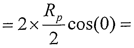
- the rotation pressure pulse height can be calculated by demodulating the cyclic pressure signal with the in phase unity amplitude sine wave:
- the method steps may be implemented by hardware in the form of controlling electronics or may be a controlling algorithm in software which is able to output the feed pressure level .
- the controller stores graphical data relating to the aforementioned rotation pressure, feed pressure and penetration rates for different types of rock types as illustrated in Figure 3.
- Figure 3 shows how the gradient changes for different rock types in a plot of torque (rotation pressure) as a function of thrust (feed pressure) .
- torque rotation pressure
- feed pressure thrust
- Figure 4 shows a relatively constant gradient for different sized drill bits .
- the graphical data can be stored as an equivalent mathematical representation which allows easier feedback control of the feed pressure using the system outlined above.
- the only parameters that need to be preset are the maximum and minimum limits on the feed and rotation pressures . Therefore the controller continually increments the value for feed pressure in accordance with the previous system to ensure that the feed pressure level is optimised between the upper and lower limits .
- the optimised feed pressure or rotation pressure so found for the drilling apparatus in use provides a measure of the drilling characteristics of the rock.
- the controller will determine new optimised drilling pressures and such pressures provide a measure of the rock type which is useful information for design and management of mines. For this example, this information may be used to indicate when the drill has crossed the boundary between ore and waste.
- the controller would be set up to monitor parameters relating to the drill apparatus and rock conditions and relate these back to stored graphical/mathematical models so that the controller can determine preferred upper and lower limits for each set of parameter values .
Abstract
Description


Claims
Priority Applications (6)
| Application Number | Priority Date | Filing Date | Title |
|---|---|---|---|
| CN2006800126253A CN101160449B (en) | 2005-02-25 | 2006-02-24 | A method and system for controlling an excavating apparatus |
| AP2007004166A AP2342A (en) | 2005-02-25 | 2006-02-24 | A method and system for controlling an excavating apparatus. |
| US11/885,082 US7921936B2 (en) | 2005-02-25 | 2006-02-24 | Method and system for controlling an excavating apparatus |
| AU2006216123A AU2006216123B2 (en) | 2005-02-25 | 2006-02-24 | A method and system for controlling an excavating apparatus |
| CA2599429A CA2599429C (en) | 2005-02-25 | 2006-02-24 | A method and system for controlling an excavating apparatus |
| EP06704916.3A EP1871989A4 (en) | 2005-02-25 | 2006-02-24 | A method and system for controlling an excavating apparatus |
Applications Claiming Priority (2)
| Application Number | Priority Date | Filing Date | Title |
|---|---|---|---|
| AU2005900871A AU2005900871A0 (en) | 2005-02-25 | A method and system for controlling an excavating apparatus | |
| AU2005900871 | 2005-02-25 |
Publications (1)
| Publication Number | Publication Date |
|---|---|
| WO2006089367A1 true WO2006089367A1 (en) | 2006-08-31 |
Family
ID=36926965
Family Applications (1)
| Application Number | Title | Priority Date | Filing Date |
|---|---|---|---|
| PCT/AU2006/000241 WO2006089367A1 (en) | 2005-02-25 | 2006-02-24 | A method and system for controlling an excavating apparatus |
Country Status (8)
| Country | Link |
|---|---|
| US (1) | US7921936B2 (en) |
| EP (1) | EP1871989A4 (en) |
| CN (1) | CN101160449B (en) |
| AP (1) | AP2342A (en) |
| AU (1) | AU2006216123B2 (en) |
| CA (1) | CA2599429C (en) |
| WO (1) | WO2006089367A1 (en) |
| ZA (1) | ZA200707536B (en) |
Cited By (1)
| Publication number | Priority date | Publication date | Assignee | Title |
|---|---|---|---|---|
| EP2173959A4 (en) * | 2007-06-26 | 2015-12-30 | Atlas Copco Rock Drills Ab | Method and device for controlling a rock drill rig |
Families Citing this family (4)
| Publication number | Priority date | Publication date | Assignee | Title |
|---|---|---|---|---|
| CN101899969B (en) * | 2010-03-24 | 2013-04-17 | 苏州锐石能源开发技术有限公司 | Real-time on-site drilling full parameter optimization method |
| CN102996139B (en) * | 2012-11-30 | 2014-12-17 | 中煤科工集团重庆研究院有限公司 | Hydraulic control system of drill loader |
| DE102013227032A1 (en) * | 2013-12-20 | 2015-06-25 | Hamm Ag | Drive system, in particular for a self-propelled construction machine, in particular soil compactor |
| EP4264010A1 (en) * | 2020-12-21 | 2023-10-25 | Epiroc Rock Drills Aktiebolag | Method and system for optimising a drilling parameter during an ongoing drilling process |
Citations (4)
| Publication number | Priority date | Publication date | Assignee | Title |
|---|---|---|---|---|
| US3971449A (en) * | 1973-10-09 | 1976-07-27 | Oy Tampella Ab | Procedure for controlling a rock drill and rock drill for carrying out the procedure |
| WO1992012329A1 (en) * | 1991-01-03 | 1992-07-23 | Tamrock Oy | A method of drilling a hole in a rock |
| US5449047A (en) * | 1994-09-07 | 1995-09-12 | Ingersoll-Rand Company | Automatic control of drilling system |
| WO1997008428A1 (en) * | 1995-08-28 | 1997-03-06 | Atlas Copco Craelius Ab | Method and device for drilling |
Family Cites Families (7)
| Publication number | Priority date | Publication date | Assignee | Title |
|---|---|---|---|---|
| FI88744C (en) * | 1991-04-25 | 1993-06-28 | Tamrock Oy | For the purposes of this Regulation |
| US6216800B1 (en) * | 1998-11-24 | 2001-04-17 | J. H. Fletcher & Co., Inc. | In-situ drilling system with dust collection and overload control |
| FI115037B (en) * | 2001-10-18 | 2005-02-28 | Sandvik Tamrock Oy | Method and arrangement for a rock drilling machine |
| FI121219B (en) * | 2001-10-18 | 2010-08-31 | Sandvik Tamrock Oy | Method and apparatus for monitoring the operation of the impactor and for adjusting the operation of the impactor |
| CN2544101Y (en) * | 2002-05-14 | 2003-04-09 | 川油广汉宏华有限公司 | Digital control frequency-changing drill feeder |
| CN1475653A (en) * | 2002-08-13 | 2004-02-18 | 中国石化集团中原石油勘探局 | Well drilling parameter collection and treatment method |
| FI121027B (en) * | 2004-09-24 | 2010-06-15 | Sandvik Mining & Constr Oy | Procedure for controlling striking rock drilling, software product and rock drilling device |
-
2006
- 2006-02-24 AU AU2006216123A patent/AU2006216123B2/en active Active
- 2006-02-24 CN CN2006800126253A patent/CN101160449B/en active Active
- 2006-02-24 WO PCT/AU2006/000241 patent/WO2006089367A1/en active Application Filing
- 2006-02-24 CA CA2599429A patent/CA2599429C/en active Active
- 2006-02-24 US US11/885,082 patent/US7921936B2/en active Active
- 2006-02-24 EP EP06704916.3A patent/EP1871989A4/en not_active Withdrawn
- 2006-02-24 AP AP2007004166A patent/AP2342A/en active
-
2007
- 2007-08-31 ZA ZA200707536A patent/ZA200707536B/en unknown
Patent Citations (4)
| Publication number | Priority date | Publication date | Assignee | Title |
|---|---|---|---|---|
| US3971449A (en) * | 1973-10-09 | 1976-07-27 | Oy Tampella Ab | Procedure for controlling a rock drill and rock drill for carrying out the procedure |
| WO1992012329A1 (en) * | 1991-01-03 | 1992-07-23 | Tamrock Oy | A method of drilling a hole in a rock |
| US5449047A (en) * | 1994-09-07 | 1995-09-12 | Ingersoll-Rand Company | Automatic control of drilling system |
| WO1997008428A1 (en) * | 1995-08-28 | 1997-03-06 | Atlas Copco Craelius Ab | Method and device for drilling |
Non-Patent Citations (1)
| Title |
|---|
| See also references of EP1871989A4 * |
Cited By (1)
| Publication number | Priority date | Publication date | Assignee | Title |
|---|---|---|---|---|
| EP2173959A4 (en) * | 2007-06-26 | 2015-12-30 | Atlas Copco Rock Drills Ab | Method and device for controlling a rock drill rig |
Also Published As
| Publication number | Publication date |
|---|---|
| CA2599429A1 (en) | 2006-08-31 |
| AU2006216123A1 (en) | 2006-08-31 |
| AP2342A (en) | 2011-12-28 |
| ZA200707536B (en) | 2008-08-27 |
| US7921936B2 (en) | 2011-04-12 |
| AP2007004166A0 (en) | 2007-10-31 |
| CA2599429C (en) | 2014-07-22 |
| CN101160449B (en) | 2012-02-08 |
| US20090114444A1 (en) | 2009-05-07 |
| EP1871989A1 (en) | 2008-01-02 |
| CN101160449A (en) | 2008-04-09 |
| EP1871989A4 (en) | 2017-01-11 |
| AU2006216123B2 (en) | 2012-06-21 |
Similar Documents
| Publication | Publication Date | Title |
|---|---|---|
| AU2021204469A1 (en) | System and method for controlling a drilling machine | |
| AU2007255124B2 (en) | Resonance enhanced drilling: method and apparatus | |
| US8939234B2 (en) | Systems and methods for improving drilling efficiency | |
| US9587443B2 (en) | Resonance enhanced rotary drilling module | |
| EP0467642A2 (en) | Earth drilling system and method for controlling the direction of a borehole | |
| CA2599429C (en) | A method and system for controlling an excavating apparatus | |
| JP7160467B2 (en) | Method and construction equipment for soil work | |
| NO320684B1 (en) | Procedure for regulating operating parameters of a drill bit | |
| CN101116009A (en) | Method for predicting rate of penetration using bit-specific coefficients of sliding friction and mechanical efficiency as a function of confined compressive strength | |
| LaBelle et al. | Material classification by drilling | |
| WO2012126898A2 (en) | Test apparatus | |
| AU2016335480B2 (en) | A method and a system for optimising energy usage at a drilling arrangement | |
| RU2265719C1 (en) | Rotation control method for rotative drilling machine rod | |
| DK2230375T3 (en) | Resonance Enhanced drilling: a method and apparatus | |
| WO2023234819A1 (en) | A method for real-time adjustment of at least one drilling parameter during rock drilling by a drilling machine |
Legal Events
| Date | Code | Title | Description |
|---|---|---|---|
| 121 | Ep: the epo has been informed by wipo that ep was designated in this application | ||
| WWE | Wipo information: entry into national phase |
Ref document number: 2006216123 Country of ref document: AU |
|
| WWE | Wipo information: entry into national phase |
Ref document number: 2599429 Country of ref document: CA |
|
| NENP | Non-entry into the national phase |
Ref country code: DE |
|
| WWE | Wipo information: entry into national phase |
Ref document number: 2006704916 Country of ref document: EP |
|
| ENP | Entry into the national phase |
Ref document number: 2006216123 Country of ref document: AU Date of ref document: 20060224 Kind code of ref document: A |
|
| WWP | Wipo information: published in national office |
Ref document number: 2006216123 Country of ref document: AU |
|
| WWE | Wipo information: entry into national phase |
Ref document number: AP/P/2007/004166 Country of ref document: AP |
|
| WWE | Wipo information: entry into national phase |
Ref document number: 200680012625.3 Country of ref document: CN |
|
| WWP | Wipo information: published in national office |
Ref document number: 2006704916 Country of ref document: EP |
|
| WWE | Wipo information: entry into national phase |
Ref document number: 11885082 Country of ref document: US |