WO2006023998A2 - Pulsed electric rock drilling, fracturing, and crushing methods and apparatus - Google Patents
Pulsed electric rock drilling, fracturing, and crushing methods and apparatus Download PDFInfo
- Publication number
- WO2006023998A2 WO2006023998A2 PCT/US2005/030178 US2005030178W WO2006023998A2 WO 2006023998 A2 WO2006023998 A2 WO 2006023998A2 US 2005030178 W US2005030178 W US 2005030178W WO 2006023998 A2 WO2006023998 A2 WO 2006023998A2
- Authority
- WO
- WIPO (PCT)
- Prior art keywords
- bit
- electrodes
- approximately
- high voltage
- drill
- Prior art date
Links
Classifications
-
- E—FIXED CONSTRUCTIONS
- E21—EARTH DRILLING; MINING
- E21C—MINING OR QUARRYING
- E21C37/00—Other methods or devices for dislodging with or without loading
- E21C37/18—Other methods or devices for dislodging with or without loading by electricity
-
- E—FIXED CONSTRUCTIONS
- E21—EARTH DRILLING; MINING
- E21B—EARTH DRILLING, e.g. DEEP DRILLING; OBTAINING OIL, GAS, WATER, SOLUBLE OR MELTABLE MATERIALS OR A SLURRY OF MINERALS FROM WELLS
- E21B7/00—Special methods or apparatus for drilling
- E21B7/14—Drilling by use of heat, e.g. flame drilling
- E21B7/15—Drilling by use of heat, e.g. flame drilling of electrically generated heat
Definitions
- the present invention relates to pulse powered drilling apparatuses and methods.
- the present invention also relates to insulating fluids of high relative permittivity (dielectric constant).
- FIG. 1 shows a process by which a conduction path or streamer is created inside rock to break it.
- An electrical potential is impressed across the electrodes which contact the rock from the high voltage electrode 100 to the ground electrode 102.
- an arc 104 or plasma is formed inside the rock 106 from the high voltage electrode to the low voltage or ground electrode.
- the expansion of the hot gases created by the arc fractures the rock.
- this streamer connects one electrode to the next, the current flows through the conduction path, or arc, inside the rock.
- the high temperature of the arc vaporizes the rock and any water or other fluids that might be touching, or are near, the arc.
- This vaporization process creates high- pressure gas in the arc zone, which expands. This expansion pressure fails the rock in tension, thus creating rock fragments.
- the '127 patent discusses using water as the fluid for the mineral disintegration process.
- insulating drilling fluid must provide high dielectric strength to provide high electric fields at the electrodes, low conductivity to provide low leakage current during the delay time from application of the voltage until the arc ignites in the rock, and high relative permittivity to shift a higher proportion of the electric field into the rock near the electrodes.
- Water provides high relative permittivity, but has high conductivity, creating high electric charge losses. Therefore, water has excellent energy storage properties, but requires extensive deionization to make it sufficiently resistive so that it does not discharge the high voltage components by current leakage through the liquid. In the deionized condition, water is very corrosive and will dissolve many materials, including metals. As a result, water must be continually conditioned to maintain the high resistivity required for high voltage applications. Even when deionized, water still has such sufficient conductivity that it is not suitable for long-duration, pulsed power applications.
- Petroleum oil provides high dielectric strength and low conductivity, but does not provide high relative permittivity. Neither water nor petroleum oil, therefore, provide all the features necessary for effective drilling.
- Propylene carbonate is another example of such insulating materials in that it has a high dielectric constant and moderate dielectric strength, but also has high conductivity (about twice that of deionized water) making it unsuitable for pulsed power applications.
- Insulating fluids are used for many electrical applications such as, for example, to insulate electrical power transformers.
- PH plasma-hydraulic
- EH electrohydraulic
- An embodiment of the present invention provides a pulsed power drilling apparatus for passing a pulsed electrical current through a mineral substrate to break a substrate, the apparatus comprising a rotatable drill bit, a high voltage pulse generator linked to said drill bit for delivering high voltage pulses, and at least one set of at least two electrodes disposed on said drill bit defining there between at least one electrode gap, said electrodes of each said set oriented substantially along a face of said drill bit, at least one of said electrodes disposed so that it touches the substrate and another of said electrodes is disposed so that it functions in close proximity to the substrate for current to pass through the substrate. At least one of the electrodes is optionally compressible toward the drill bit.
- the apparatus optionally comprises a plurality of mechanical teeth disposed on the bit.
- the apparatus optionally comprises an insulating drilling fluid having an electrical conductivity less than approximately 10 '5 mho/cm and a dielectric constant greater than approximately 6.
- the insulating drilling fluid optionally comprises treated water having a conductivity less than approximately 10 "4 mho/cm and a dielectric constant greater than approximately 6.
- the insulating fluid optionally comprises at least one oil.
- the insulating fluid optionally comprises a dielectric strength of at least approximately 300 kV/cm (1 ⁇ sec), a dielectric constant of at least approximately 15, and a conductivity of less than approximately 10 '5 mho/cm.
- At least one of the electrode sets is optionally arranged on the bit in a configuration that is asymmetric relative to the axis of rotational symmetry of the bit, optionally arranged on the bit in a configuration that is symmetric relative to the axis of rotational symmetry of the bit, and optionally arranged on the bit in a configuration that is asymmetric relative to the axis of rotational symmetry of the bit and wherein at least another one of the electrode sets is arranged on the bit in a configuration that is symmetric relative to the axis of rotational symmetry of the bit.
- the electrodes are optionally radiused on a side where the electrodes contact the substrate.
- the bit is optionally substantially conical in shape.
- the conical bit optionally comprises conical sides comprising two angles.
- the bit optionally comprises a geometric shape selected from the group consisting of a substantially conical shape, a substantially conical and truncated shape, a substantially cylindrical shape, a substantially elliptical paraboloid, and a combination thereof.
- the bit optionally comprises a plurality of geometric shapes including, but not limited to, a substantially conical shape, a substantially conical and truncated shape, a substantially cylindrical shape, a substantially elliptical paraboloid, a substantially planar shape, or a combination thereof.
- the apparatus further optionally comprises a rotary drill reamer disposed on a drill string on which the drill bit is disposed so that the rotary drill reamer and the drill bit operate in conjunction on same drill string.
- the reamer optionally comprises a reamer such as, but not limited to, a drag bit, a tapered drag bit, a rotary bit, or a combination thereof.
- At least one set of electrodes is optionally disposed at a longitudinal center of the bit and the same, or another set, optionally disposed off-center of rotation of the bit.
- the apparatus further optionally comprises an electrical conduction conduit to send high voltage pulses to the drill bit from the high voltage pulse generator.
- the conduit optionally comprises a cable.
- a high voltage pulse generator is optionally disposed on the surface of the ground and further comprising an electrical conduction conduit linking the generator and the drill bit to send high voltage pulses from the generator to the drill bit.
- the apparatus further optionally comprises a pulsed power system disposed on or near the drill bit for conditioning electrical current received by the drill bit.
- the pulse power generator optionally comprises a capacitor bank comprising a switch such as, but not limited to, a spark gap, a thyratron, a vacuum gap, a pseudo-spark switch, a mechanical switch, solid state switch, or a combination thereof.
- a switch such as, but not limited to, a spark gap, a thyratron, a vacuum gap, a pseudo-spark switch, a mechanical switch, solid state switch, or a combination thereof.
- the pulse power source optionally comprises a source such as, but not limited to, a rotating electromagnetic power generator located on the surface of the ground, a rotating electromagnetic power generator located downhole, a utility power grid located on the surface, a piezoelectric power generator located downhole, a fuel cell electric power generator located at the surface of the ground, or a fuel cell electric power generator located downhole.
- a source such as, but not limited to, a rotating electromagnetic power generator located on the surface of the ground, a rotating electromagnetic power generator located downhole, a utility power grid located on the surface, a piezoelectric power generator located downhole, a fuel cell electric power generator located at the surface of the ground, or a fuel cell electric power generator located downhole.
- the apparatus further optionally comprises a cable or electrical conduction means to send electrical power from a power source to the high voltage pulse generator.
- the high voltage pulse generator delivers high voltage pulses of at least approximately 100 kV.
- the apparatus further optionally comprises passages disposed in the bit in which a flow of fluid is disposed for flushing debris.
- a pulsed power drilling apparatus for passing a pulsed electrical current through a mineral substrate to break the substrate
- the apparatus comprising a rotatable drill bit, a high voltage pulse power generator linked to the drill bit for delivering high voltage pulses, an electrical power source to power the high voltage pulse generator, at least one set of at least two electrodes disposed on the drill bit defining therebetween at least one electrode gap, the electrodes of each the set oriented substantially parallel to one another along a face of the drill bit; at least one of the electrodes disposed so that it touches the substrate and another of the electrodes is disposed so that it functions in close proximity to the substrate for current to pass through the substrate, and an insulating drilling fluid having an electrical conductivity less than approximately 10 '4 mho/cm and a dielectric constant greater than approximately 6.
- the insulating fluid optionally has a conductivity of less than approximately 10 '5 mho/cm, optionally comprises treated water having a conductivity less than approximately 10 "4 mho/cm, and optionally comprises at least one oil. 34.
- the insulating fluid optionally comprises a dielectric strength of at least approximately 300 kV/cm (1 ⁇ sec), a dielectric constant of at least approximately 6, and a conductivity of less than approximately 10 "5 mho/cm.
- the apparatus optionally comprises a plurality of mechanical teeth disposed on the bit.
- the apparatus optionally comprises at least one of the electrodes that are depressible or compressible toward the drill bit.
- the electrode sets are optionally arranged on the bit in a configuration that is asymmetric relative to the axis of rotational symmetry of the bit, optionally arranged on the bit in a configuration that is symmetric relative to the axis of rotational symmetry of the bit, and optionally arranged on the bit in a configuration that is asymmetric relative to the axis of rotational symmetry of the bit and wherein at least one other of the electrode sets is arranged on the bit in a configuration that is symmetric relative to the axis of rotational symmetry of the bit.
- the electrodes are optionally radiused on a side where the electrodes contact the substrate.
- the bit optionally comprises a geometric shape such as, but not limited to, a substantially conical shape, a substantially conical and truncated shape, a substantially cylindrical shape, a substantially elliptical paraboloid, or a combination thereof.
- the bit optionally comprises a plurality of geometric shapes such as, but not limited to a substantially conical shape, a substantially conical and truncated shape, a substantially cylindrical shape, a substantially elliptical paraboloid, a substantially planar shape, or a combination thereof.
- the apparatus optionally comprises a rotary drill reamer disposed on a drill string on which the drill bit is disposed so that the rotary drill reamer and the drill bit operate in conjunction on same drill string, and the reamer optionally comprises a reamer such as, but not limited to, a drag bit, a tapered drag bit, a rotary bit, or a combination thereof.
- At least one set of electrodes is optionally disposed at a longitudinal center of the bit, and optionally disposed off-center of rotation of the bit, or if more than one set, in disposed in a combination of the center of off-center.
- the apparatus optionally comprises an electrical conduction conduit to send high voltage pulses to the drill bit from the high voltage pulse generator, and the conduit optionally comprises a cable.
- the high voltage pulse generator is optionally disposed on the surface of the ground and further comprising an electrical conduction conduit linking the generator and the drill bit to send high voltage pulses from the generator to the drill bit.
- the apparatus further optionally comprises a pulsed power system disposed on or near the drill bit for conditioning electrical current received by the drill bit.
- the pulse power generator optionally comprises a capacitor bank comprising at least one switch such as, but not limited to, a spark gap, a thyratron, a vacuum gap, a pseudo-spark switch, a mechanical switch, solid state switch, or a combination thereof.
- a capacitor bank comprising at least one switch such as, but not limited to, a spark gap, a thyratron, a vacuum gap, a pseudo-spark switch, a mechanical switch, solid state switch, or a combination thereof.
- the pulse power source optionally comprises a rotating electromagnetic power generator located on the surface of the ground, a rotating electromagnetic power generator located downhole, a utility power grid located on the surface, a piezoelectric power generator located downhole, a fuel cell electric power generator located at the surface of the ground, or a fuel cell electric power generator located downhole.
- the apparatus optionally comprises a cable or electrical conduction means to send electrical power from a power source to the high voltage pulse generator.
- the high voltage pulse generator delivers high voltage pulses of at least approximately 100 kV.
- the apparatus optionally further comprises passages disposed in the bit and in which a flow of fluid is disposed for flushing debris.
- a pulsed power drilling apparatus for passing a pulsed electrical current through a mineral substrate to break a substrate
- the apparatus comprising a drill bit, at least one set of at least two electrodes disposed on the drill bit defining therebetween at least one electrode gap, at least one of the electrodes disposed so that it touches the substrate and another of the electrodes disposed so that it functions in close proximity to the substrate for current to pass through the substrate, a high voltage pulse generator linked to the drill bit for delivering a pulsed power current between the electrodes and through the substrate to break the substrate, the high voltage pulse generator powered by an electrical power source, or a passage for delivering a fluid down the drilling apparatus.
- Another embodiment of the present invention comprises an apparatus for mining rock comprising a plurality of the drill bits arranged in an array, each drill bit comprising at least one set of at least two electrodes disposed on the drill bit defining therebetween at least one electrode gap, at least one of the electrodes disposed so that it touches the substrate and another of the electrodes disposed so that it functions in close proximity to the substrate for current to pass through the substrate, at least one high voltage pulse generator linked to the drill bits for delivering a pulsed power current between the electrodes and through the substrate to break the substrate, the at least one high voltage pulse generator powered by an electrical power source, or a passage for delivering a fluid down the drill bits.
- the fluid of the apparatus is disposed about the substrate during operation of the apparatus.
- the array optionally further comprises a plurality of electrohydraulic drill bits.
- the apparatus optionally further comprising a component for steering the array by varying the repetition rate and/or pulse energy of some of the drill bits relative other drill bits in the array.
- At least one of the electrodes in at least one of the drill bits is compressible or depressible toward the at least one drill bit.
- the apparatus optionally further comprises at least one cable for connecting the at least one high voltage pulse generator to at least one of the electrodes.
- Another embodiment of the present invention provides a method for breaking and drilling a mineral substrate comprising providing a drill bit, disposing at least one set of electrodes on the drill bit, rotating the drill bit, and delivering a pulsed power current between the electrodes and through the substrate to break the substrate, at least one set of at least two electrodes disposed on the drill bit defining there between at least one electrode gap, orienting the electrodes of each the set substantially along a face of the drill bit, disposing at least one of the electrodes so that it touches the substrate and another of the electrodes is disposed so that it functions in close proximity to the substrate for current to pass through the substrate.
- the method optionally further comprises disposing a drilling fluid about the substrate to be drilled.
- the method optionally further comprises depressing at least one of the electrodes into the drill bit during operation.
- the method optionally further comprises disposing a plurality of mechanical teeth on the bit.
- the insulating drilling fluid optionally has an electrical conductivity less than approximately 10 "5 mho/cm and a dielectric constant greater than approximately 6, optionally comprises treated water having a conductivity less than approximately 10 '4 mho/cm and a dielectric constant greater than approximately 6, and optionally comprises at least one oil.
- the insulating fluid optionally comprises a dielectric strength of at least approximately 300 kV/cm (1 ⁇ sec), a dielectric constant of at least approximately 15, and a conductivity of less than approximately 10 '5 mho/cm.
- the method of further optionally comprises arranging at least one of the electrode sets on the bit in a configuration that is asymmetric relative to the axis of rotational symmetry of the bit.
- the method optionally comprises arranging at least one of the electrode sets on the bit in a configuration that is symmetric relative to the axis of rotational symmetry of the bit.
- the method optionally further comprises arranging at least one of the electrode sets on the bit in a configuration that is asymmetric relative to the axis of rotational symmetry of the bit and further arranging at least one of the electrode sets on the bit in a configuration that is symmetric relative to the axis of rotational symmetry of the bit.
- the electrodes are optionally radiused on a side where the electrodes contact the substrate.
- the bit optionally is substantially conical in shape.
- the conical bit optionally comprises conical sides comprising two angles.
- the bit optionally comprises a geometric shape such as, but not limited to, a substantially conical shape, a substantially conical and truncated shape, a substantially cylindrical shape, or a substantially elliptical paraboloid, or a combination thereof, and optionally comprises a plurality of geometric shapes such as, but not limited to, a substantially conical shape, a substantially conical and truncated shape, a substantially cylindrical shape, a substantially elliptical paraboloid, a substantially planar shape, or a combination thereof.
- the method further optionally comprises disposing a rotary drill reamer and the drill bit on a common drill string and operating the rotary drill reamer and the drill bit in conjunction, and the reamer optionally comprises, but is not limited to, a drag bit, a tapered drag bit, a rotary bit, or a combination thereof.
- the method optionally comprises disposing at least one of the set of electrodes at a longitudinal center of the bit or optionally off-center of rotation of the bit, or in a combination thereof.
- the method further comprising providing an electrical conduction conduit and sending high voltage pulses from the high voltage pulse generator to the drill bit, and the conduit optionally comprises a cable.
- the method optionally comprises disposing the high voltage pulse generator on the surface of the ground and further comprising providing an electrical conduction conduit to link the generator and the drill bit and sending high voltage pulses from the generator to the drill bit.
- the method optionally further comprises disposing a pulsed power system on or near the drill bit for conditioning electrical current received by the drill bit.
- the pulse power generator optionally comprises a capacitor bank comprising at least one switch such as, but not limited to, a spark gap, a thyratron, a vacuum gap, a pseudo-spark switch, a mechanical switch, solid state switch, or a combination thereof.
- the pulse power source optionally comprises a rotating electromagnetic power generator located on the surface of the ground, a rotating electromagnetic power generator located downhole, a utility power grid located on the surface, a piezoelectric power generator located downhole, a fuel cell electric power generator located at the surface of the ground, or a fuel cell electric power generator located downhole.
- the method optionally comprises providing a cable or electrical conduction means and sending electrical power from a power source to the high voltage pulse generator via the cable or electrical conduction means.
- the method optionally comprises delivering high voltage pulses of at least approximately 100 kV from the high voltage pulse generator.
- the method optionally comprises disposing passages in the bit and sending a flow of fluid through the passages for flushing debris.
- Another embodiment of the present invention provides a method for passing a pulsed electrical current through a mineral substrate to break the substrate, the method comprising, providing drill bit, linking a high voltage pulse power generator linked to the drill bit for delivering high voltage pulses, providing an electrical power source to power the high voltage pulse generator, disposing at least one set of at least two electrodes on the drill bit defining therebetween at least one electrode gap, substantially orienting the electrodes of each the set parallel to one another along a face of the drill bit; disposing at least one of the electrodes so that it touches the substrate and disposing another of the electrodes so that it functions in close proximity to the substrate for current to pass through the substrate, rotating the drill bit, and providing an insulating drilling fluid having an electrical conductivity less than approximately 10 "4 mho/cm and a dielectric constant greater than approximately 6.
- the insulating fluid optionally has a conductivity of less than approximately 10 '5 mho/cm, optionally comprises treated water having a conductivity less than approximately 10 '4 mho/cm, and optionally comprises at least one oil. 96.
- the insulating fluid optionally comprises a dielectric strength of at least approximately 300 kV/cm (1 ⁇ sec), a dielectric constant of at least approximately 6, and a conductivity of less than approximately 10 '5 mho/cm.
- the method optionally comprises disposing a plurality of mechanical teeth on the bit.
- the method further optionally comprises depressing or compressing at least one of the electrodes into the drill bit during drilling.
- the method optionally comprises arranging at least one of the electrode sets on the bit in a configuration that is asymmetric relative to the axis of rotational symmetry of the bit, optionally comprises arranging at least one of the electrode sets on the bit in a configuration that is symmetric relative to the axis of rotational symmetry of the bit, and optionally comprises arranging at least one of the electrode sets on the bit in a configuration that is asymmetric relative to the axis of rotational symmetry of the bit and arranging at least one of the other electrode sets on the bit in a configuration that is symmetric relative to the axis of rotational symmetry of the bit, or in a combination thereof.
- the method optionally comprises providing electrodes that are radiused on a side where the electrodes contact the substrate.
- the bit optionally comprises a geometric shape such as, but not limited to, a substantially conical shape, a substantially conical and truncated shape, a substantially cylindrical shape, a substantially elliptical paraboloid, or a combination thereof.
- the bit optionally comprises a plurality of geometric shapes such as, but not limited to, a substantially conical shape, a substantially conical and truncated shape, a substantially cylindrical shape, a substantially elliptical paraboloid, a substantially planar shape, or a combination thereof.
- the method optionally comprises disposing a rotary drill reamer and the drill bit on a common drill string and operating the rotary drill reamer and the drill bit in conjunction, and the reamer optionally comprises, but is not limited to, a drag bit, a tapered drag bit, a rotary bit, or a combination thereof.
- the method optionally comprises disposing at least one set of electrodes at a longitudinal center of the bit, and optionally comprises disposing at least one set of electrodes off-center of rotation of the bit, and optionally comprises disposing the electrodes in a combination of the orientations.
- the method optionally comprises providing an electrical conduction conduit and sending high voltage pulses from the high voltage pulse generator to the drill bit via the conduit, and the conduit optionally comprises a cable.
- the method optionally comprises disposing the high voltage pulse generator on the surface of the ground and further comprising providing an electrical conduction conduit, linking the generator and the drill bit via the conduit, and sending high voltage pulses from the generator to the drill bit via the conduit.
- the method optionally comprises disposing a pulsed power system on or near the drill bit for conditioning electrical current received by the drill bit.
- the pulse power generator optionally comprises a capacitor bank comprising at least one switch such as, but not limited to, a spark gap, a thyratron, a vacuum gap, a pseudo-spark switch, a mechanical switch, solid state switch, or a combination thereof.
- the pulse power source comprises a source such as, but not limited to, a rotating electromagnetic power generator located on the surface of the ground, a rotating electromagnetic power generator located downhole, a utility power grid located on the surface, a piezoelectric power generator located downhole, a fuel cell electric power generator located at the surface of the ground, or a fuel cell electric power generator located downhole.
- a source such as, but not limited to, a rotating electromagnetic power generator located on the surface of the ground, a rotating electromagnetic power generator located downhole, a utility power grid located on the surface, a piezoelectric power generator located downhole, a fuel cell electric power generator located at the surface of the ground, or a fuel cell electric power generator located downhole.
- the method optionally comprises providing a cable or electrical conduction means and sending electrical power from a power source to the high voltage pulse generator via the cable or electrical conduction means.
- the method optionally comprises delivering high voltage pulses of at least approximately 100 kV from the high voltage pulse generator.
- the method optionally comprises disposing passages in the bit and providing a flow of fluid in the passages for flushing debris.
- Another embodiment of the present invention provides a pulsed power drilling method for passing a pulsed electrical current through a mineral substrate to break the substrate, the method comprising providing a drill bit, disposing at least one set of at least two electrodes the drill bit defining therebetween at least one electrode gap, disposing at least one of the electrodes so that it touches the substrate and disposing another of the electrodes so that it functions in close proximity to the substrate for current to pass through the substrate, linking a high voltage pulse generator to the drill bit, delivering a pulsed power current between the electrodes and through the substrate to break the substrate, the high voltage pulse generator powered by an electrical power source, and disposing a passage in the drilling method and delivering a fluid down the drilling method.
- Another embodiment of the present invention provides a method for mining rock comprising arranging a plurality of the drill bits in an array, disposing at least one set of at least two electrodes on each drill bit defining therebetween at least one electrode gap, disposing at least one of the electrodes so that it touches the substrate and disposing another of the electrodes so that it functions in close proximity to the substrate for current to pass through the substrate, linking at least one high voltage pulse generator to the drill bits and delivering a pulsed power current between the electrodes and through the substrate to break the substrate, providing an electrical power source for powering the at least one high voltage pulse generator, providing a passage for delivering a fluid down the drill bits, and delivering a fluid down the drill bits.
- the method optionally comprises disposing the fluid about the substrate during operation of the drill bits.
- the method optionally further comprises disposing a plurality of electrohydraulic drill bits in the array.
- the method optionally further comprises steering the array by varying the repetition rate and/or pulse energy of some of the drill bits relative other drill bits in the array.
- the method of further optionally comprises depressing at least one of the electrodes in at least one of the drill bits into the at least one drill bit during operation of the drill bits.
- the method optionally further comprises connecting the at least one high voltage pulse generator to at least one of the electrodes via at least one cable.
- Another embodiment of the present invention provides an electrical insulating formulation comprising a first, carbon-based material having a dielectric constant greater than approximately 2.6, second, carbon-based material, different from the first material, having a dielectric constant greater than approximately 10.0, the first material at least partially miscible with the second material and the insulating formulation having low electrical conductivity.
- the first material and the second material are preferably substantially non-aqueous.
- the first material optionally comprises one or more oils, optionally comprises one or more natural or synthetic oils, optionally comprises castor oil, optionally comprises jojoba oil, and optionally comprises mineral oil.
- the second material optionally comprises one or more solvents, optionally comprises one or more carbonates, optionally comprises one or more alkylene carbonates, and optionally comprises butylene carbonate.
- the first material optionally comprises a solution comprising one or more oils and the first material is in a concentration of from between approximately 1.0 and 99.0 percent by volume and wherein the second material comprises a solution comprising one or more alkylene carbonates and the second material is in a concentration of from between approximately 1.0 and 99.0 percent by volume.
- the first material optionally comprises a solution comprising one or more oils and the first material is in a concentration of from between approximately 40.0 and 95.0 percent by volume and wherein the second material comprises a solution comprising one or more alkylene carbonates and the second material is in a concentration of from between approximately 5.0 and 60.0 percent by volume.
- the first material optionally comprises a solution comprising one or more oils and the first material is in a concentration of from between approximately 65.0 and 90.0 percent by volume and wherein the second material comprises a solution comprising one or more alkylene carbonates and the second material is in a concentration of from between approximately 10.0 and 35.0 percent by volume.
- the first material optionally comprises a solution comprising one or more oils and the first material is in a concentration of from between approximately 75.0 and 85.0 percent by volume and wherein the second material comprises a solution comprising one or more alkylene carbonates and the second material is in a concentration of from between approximately 15.0 and 25.0 percent by volume.
- the first material and the second material are preferably biodegradable, preferably, non ⁇ toxic and preferably not hazardous to the environment.
- Another embodiment of the present invention provides a method for drilling in hard materials comprising providing a first material having a dielectric constant of greater than approximately 2.6, mixing the first material with a second material having a dielectric constant greater than approximately 10.0 to provide an insulating formulation comprising a low electrical conductivity, and disposing the formulation about a drilling environment to provide electrical insulation for a drilling process.
- the first material and the second material are preferably substantially non-aqueous.
- the first material optionally comprises one or more oils, optionally comprises one or more natural or synthetic oils, optionally comprises castor oil, optionally comprises jojoba oil, and optionally comprises mineral oil.
- the second material optionally comprises one or more solvents, optionally comprises one or more carbonates, optionally comprises one or more alkylene carbonates, and optionally comprises butylene carbonate.
- the first material optionally comprises a solution comprising one or more oils and the first material is in a concentration of from between approximately 1.0 and 99.0 percent by volume and wherein the second material comprises a solution comprising one or more alkylene carbonates and the second material is in a concentration of from between approximately 1.0 and 99.0 percent by volume.
- the first material optionally comprises a solution comprising one or more oils and the first material is in a concentration of from between approximately 40.0 and 95.0 percent by volume and wherein the second material comprises a solution comprising one or more alkylene carbonates and the second material is in a concentration of from between approximately 5.0 and 60.0 percent by volume.
- the formulation optionally comprises a solution comprising one or more oils and the first material is in a concentration of from between approximately 65.0 and 90.0 percent by volume and wherein the second material comprises a solution comprising one or more alkylene carbonates and the second material is in a concentration of from between approximately 10.0 and 35.0 percent by volume.
- the first material optionally comprises a solution comprising one or more oils and the first material is in a concentration of from between approximately 75.0 and 85.0 percent by volume and wherein the second material comprises a solution comprising one or more alkylene carbonates and the second material is in a concentration of from between approximately 15.0 and 25.0 percent by volume.
- the first material and the second material are preferably biodegradable, preferably, non ⁇ toxic and preferably not hazardous to the environment.
- Another embodiment of the present invention provides an electrical insulating formulation comprising, castor oil, butylene carbonate, a dielectric strength of at least approximately 300 kV/cm (1 ⁇ sec), a dielectric constant of at least approximately 6, and a conductivity of less than approximately 10 "5 mho/cm.
- the formulation optionally comprises a conductivity of less than approximately 10 '6 mho/cm.
- Another embodiment of the present invention provides an assembly for creating a pressure pulse in a liquid-filled cavity within a fracturable material, the assembly comprising, a transducer, an integral energy storage component disposed in the transducer, a cable connected to the transducer storage component for delivery of electric current, and a plurality of electrodes in the transducer for converting the electrical current into a plasma pressure source.
- the assembly optionally further comprising a switch disposed in the transducer to connect the energy storage component to the electrodes.
- the assembly optionally further comprises a high voltage capacitor bank to provide a high voltage pulse to the transducer via the cable.
- the capacitor bank optionally comprises a switch such as, but not limited to, a spark gap, a thyratron, a vacuum gap, a pseudo-spark switch, a mechanical switch, a solid state switch, or a combination thereof.
- the assembly optionally further comprises an inductive storage component to provide a high voltage pulse to the transducer via the cable.
- the energy storage component optionally comprises a capacitor bank, and optionally comprises an inductive energy storage unit.
- Another embodiment of the present invention provides an assembly for creating pressure waves in a liquid to fracture material, the assembly comprising a transducer, and one or more pairs of electrodes disposed on the transducer, the electrodes defining a gap therebetween through which an electrical current passes to create pressure through expansion of liquid as it undergoes a phase change to gas or plasma.
- More than one set of electrodes is optionally arranged in parallel, and optionally arranged in a line or series of straight lines.
- the electrode sets are optionally arranged in a geometric configuration, and the configuration may comprise a configuration such as, but not limited to, a straight line, a curve, a circle, a spiral, or a combination thereof.
- the electrode sets are optionally disposed in the transducer so that the electrodes provide capacitance between each intermediate electrode and the ground structure of the transducer.
- the capacitance is optionally formed via a liquid disposed between the intermediate electrode and the ground structure.
- the capacitance is optionally formed via a capacitor disposed between the intermediate electrode and the ground structure.
- the capacitor optionally comprises a solid or liquid dielectric material.
- the assembly optionally comprises a liquid or capacitor between the electrodes to form the capacitance.
- the assembly optionally comprises an integral energy storage module to supply electrical energy to a multi-gap transducer.
- the assembly optionally further comprises an energy storage device located away from the fracturable material and area wherein the f racturable material is disposed, and a cable to connect the integral energy storage module to the energy storage device.
- Another embodiment of the present invention comprises a method for breaking mineral particles comprising suspending the particles in a liquid disposed in a container, the liquid comprising a dielectric constant higher than the particles, disposing a plurality of electrodes in the liquid, sending an electric voltage pulse to the electrodes wherein the pulse is tuned to electrical characteristics of the container and liquid to provide a rise of voltage sufficient to allocate an electric field in the mineral particles with sufficient stress to fracture the mineral particles, and passing sufficient current through the mineral particles to fracture the mineral particles.
- the liquid optionally flows slowly upward in a column so that small, fractured particles are carried upward by the upwardly flowing liquid while larger, heavier, unfractured particles sink past the electrodes.
- the gaps between the electrodes optionally are larger than the size of the mineral particles.
- the liquid flows optionally flows slowly upward in a column so that small, fractured particles are carried upward by the upwardly flowing liquid while larger, heavier, unfractured particles sink past the electrodes, and wherein gaps between the electrodes are larger than the size of the mineral particles.
- Another embodiment of the present invention provides an apparatus for breaking mineral particles comprising a container, a liquid disposed in the container in which the particles are suspended, the liquid comprising a dielectric constant higher than the particles, a plurality of electrodes disposed in the liquid, and a pulsed power source for sending an electric voltage pulse to the electrodes wherein the pulse is tuned to electrical characteristics of the container and the liquid to provide a rise of voltage sufficient to allocate an electric field in the mineral particles with sufficient stress to fracture the mineral particles.
- the liquid optionally flows slowly upward in a column so that small, fractured particles are carried upward by the upwardly flowing liquid while larger, heavier, unfractured particles sink past the electrodes.
- the gaps between the electrodes optionally are larger than the size of the mineral particles.
- the liquid optionally flows slowly upward in a column so that small, fractured particles are carried upward by the upwardly flowing liquid while larger, heavier, unfractured particles sink past the electrodes, and wherein gaps between the electrodes are larger than the size of the mineral particles.
- Fig. 1 shows an electrocrushing process of the prior art
- Fig. 2 shows an end view of a coaxial electrode set for a cylindrical bit of an embodiment of the present invention
- Fig. 3 shows an alternate embodiment of Fig. 2;
- Fig. 4 shows an alternate embodiment of a plurality of coaxial electrode sets
- Fig. 5 shows a conical bit of an embodiment of the present invention
- Fig. 6 is of a dual-electrode set bit of an embodiment of the present invention.
- Fig. 7 is of a dual-electrode conical bit with two different cone angles of an embodiment of the present invention.
- Fig. 8 shows an embodiment of a drill bit of the present invention wherein one ground electrode is the tip of the bit and the other ground electrode has the geometry of a great circle of the cone;
- Fig. 9 shows the range of bit rotation azimuthal angle of an embodiment of the present invention
- Fig. 10 shows an embodiment of the drill bit of the present invention having radiused electrodes
- Fig. 11 shows the complete drill assembly of an embodiment of the present invention
- Fig. 12 shows the reamer drag bit of an embodiment of the present invention
- Fig. 13 shows a solid-state switch or gas switch controlled high voltage pulse generating system that pulse charges the primary output capacitor of an embodiment of the present invention
- Fig. 14 shows an array of solid-state switch or gas switch controlled high voltage pulse generating circuits that are charged in parallel and discharged in series to pulse-charge the output capacitor of an embodiment of the present invention
- Fig. 15 shows a voltage vector inversion circuit that produces a pulse that is a multiple of the charge voltage of an embodiment of the present invention
- Fig. 16 shows an inductive store voltage gain system to produce the pulses needed for the FAST Drill of an embodiment of the present invention
- Fig. 17 shows a drill assembly powered by a fuel cell that is supplied by fuel lines and exhaust line from the surface inside the continuous metal mud pipe of an embodiment of the present invention
- Fig. 18 shows a roller-cone bit with an electrode set of an embodiment of the present invention
- Fig. 19 shows a small-diameter electrocrushing drill of an embodiment of the present invention
- Fig. 20 shows an electrocrushing vein miner of an embodiment of the present invention
- Fig. 21 shows a water treatment unit useable in the embodiments of the present invention
- Fig. 22 shows a high energy electrohydraulic boulder breaker system (HEEB) of an embodiment of the present invention
- Fig. 23 shows a transducer of the embodiment of Fig. 22
- Fig. 24 shows the details of the an energy storage module and transducer of the embodiment of Fig. 22;
- Fig. 25 shows the details of an inductive storage embodiment of the high energy electrohydraulic boulder breaker energy storage module and transducer of an embodiment of the present invention
- Fig. 26 shows the embodiment of the high energy electrohydraulic boulder breaker disposed on a tractor for use in a mining environment
- Fig. 27 shows a geometric arrangement of the embodiment of parallel electrode gaps in a transducer in a spiral configuration.
- Fig. 28 shows details of another embodiment of an electrohydraulic boulder breaker system
- Fig. 29 shows an embodiment of a virtual electrode electrocrushing process
- Fig. 30 shows an embodiment of the virtual electrode electrocrushing system comprising a vertical flowing fluid column
- Fig. 31 shows a pulsed power drilling apparatus manufactured and tested in accordance with an embodiment of the present invention.
- Fig. 32 is a graph showing dielectric strength versus delay to breakdown of the insulating formulation of the present invention, oil, and water.
- the present invention provides for pulsed power breaking and drilling apparatuses and methods.
- “drilling” is defined as excavating, boring into, making a hole in, or otherwise breaking and driving through a substrate.
- bit and “drill bit” are defined as the working portion or end of a tool that performs a function such as, but not limited to, a cutting, drilling, boring, fracturing, or breaking action on a substrate (e.g., rock).
- the term “pulsed power” is that which results when electrical energy is stored (e.g., in a capacitor or inductor) and then released into the load so that a pulse of current at high peak power is produced.
- “Electrocrushing” (“EC”) is defined herein as the process of passing a pulsed electrical current through a mineral substrate so that the substrate is “crushed” or “broken”.
- An embodiment of the present invention provides a drill bit on which is disposed one or more sets of electrodes.
- the electrodes are disposed so that a gap is formed between them and are disposed on the drill bit so that they are oriented along a face of the drill bit.
- the electrodes between which an electrical current passes through a mineral substrate are not on opposite sides of the rock. Also, in this embodiment, it is not necessary that all electrodes touch the mineral substrate as the current is being applied.
- At least one of the electrodes extending from the bit toward the substrate to be fractured may be compressible (i.e., retractable or depressible) into the drill bit by any means known in the art such as, for example, via a spring-loaded mechanism.
- the electrodes are disposed on the bit such that at least one electrode contacts the mineral substrate to be fractured and another electrode that usually touches the mineral substrate but otherwise may be close to, but not necessarily touching, the mineral substrate so long as it is in sufficient proximity for current to pass through the mineral substrate.
- the electrode that need not touch the substrate is the central, not the surrounding, electrode.
- the electrodes are disposed on a bit and arranged such that electrocrushing arcs are created in the rock.
- High voltage pulses are applied repetitively to the bit to create repetitive electrocrushing excavation events.
- Electrocrushing drilling can be accomplished, for example, with a flat-end cylindrical bit with one or more electrode sets. These electrodes can be arranged in a coaxial configuration.
- Fig. 2 shows an end view of such a coaxial electrode set configuration for a cylindrical bit, showing high voltage or center electrode 108, ground or surrounding electrode 110, and gap 112 for creating the arc in the rock. Variations on the coaxial configuration are shown in Fig. 3.
- a non-coaxial configuration of electrode sets arranged in bit housing 114 is shown in Fig. 4.
- Figs. 3- 4 show ground electrodes that are completed circles. Other embodiments may comprise ground electrodes that are partial circles, partial or compete ellipses, or partial or complete parabolas in geometric form.
- a conical bit is preferably utilized, especially if controlling the direction of the hole is important.
- Such a bit may comprise one or more sets of electrodes for creating the electrocrushing arcs and may comprise mechanical teeth to assist the electrocrushing process.
- One embodiment of the conical electrocrushing bit has a single set of electrodes, preferably arranged coaxially on the bit, as shown in Fig. 5.
- conical bit 118 comprises a center electrode 108, the surrounding electrode 110, the bit case or housing 114 and mechanical teeth 116 for drilling the rock. Either, or both, electrodes may be compressible.
- the surrounding electrode preferably has mechanical cutting teeth 109 incorporated into the surface to smooth over the rough rock texture produced by the electrocrushing process.
- the inner portion of the hole is drilled by the electrocrushing portion (i.e., electrodes 108 and 110) of the bit, and the outer portion of the hole is drilled by mechanical teeth 116.
- the mechanical teeth have good drilling efficiency at high velocity near the perimeter of the bit, but very low efficiency at low velocity near the center of the bit.
- the geometrical arrangement of the center electrode to the ground ring electrode is conical with a range of cone angles from 180 degrees (flat plane) to about 75 degrees (extended center electrode).
- An alternate embodiment is to arrange a second electrode set on the conical portion of the bit.
- one set of the electrocrushing electrodes operates on just one side of the bit cone in an asymmetrical configuration as exemplified in Fig. 6 which shows a dual- electrode set conical bit, each set of electrodes comprising center electrode 108, surrounding electrode 110, bit case or housing 114, mechanical teeth 116, and drilling fluid passage 120.
- the combination of the conical surface on the bit and the asymmetry of the electrode sets results in the ability of the dual-electrode bit to excavate more rock on one side of the hole than the other and thus to change direction.
- the repetition rate and pulse energy of the high voltage pulses to the electrode set on the conical surface side of the bit is maintained constant per degree of rotation.
- the pulse repetition rate (and/or pulse energy) per degree of rotation is increased over the repetition rate for the rest of the circle. In this fashion, more rock is removed by the conical surface electrode set in the turning direction and less rock is removed in the other directions (See Fig. 9, discussed in detail below). Because of the conical shape of the bit, the drill tends to turn into the section where greater amount of rock was removed and therefore control of the direction of drilling is achieved.
- EC electrocrushing
- the mechanical teeth 116 also serve to cut the gauge of the hole, that is, the relatively precise, relatively smooth inside diameter of the hole.
- An alternate embodiment has the drill bit of Fig. 6 without mechanical teeth 116, all of the drilling being done by the electrode sets 108 and 110 with or without mechanical teeth 109 in the surrounding electrode 110.
- FIG. 7 shows such an arrangement in the form of a dual-electrode conical bit comprising two different cone angles with center electrodes 108, surrounding or ground electrodes 110, and bit case or housing 114.
- the ground electrodes are tip electrode 111 and conical side ground electrodes 110 which surround, or partially surround, high voltage electrodes 108 in an asymmetric configuration.
- the bit may comprise two or more separate cone angles to enhance the ability to control direction with the bit.
- the electrodes can be laid out symmetrically in a sector of the cone, as shown in Fig. 5 or in an asymmetric configuration of the electrodes utilizing ground electrode 111 as the center of the cone as shown in Fig. 7.
- Another configuration is shown in Fig. 8A in which ground electrode 111 is at the tip of the bit and hot electrode 108 and other ground electrode 110 are aligned in great circles of the cone.
- Fig. 8B shows an alternate embodiment wherein ground electrode 111 is the tip of the bit, other ground electrode 110 has the geometry of a great circle of the cone, and hot electrodes 108 are disposed there between. Also, any combination of these configurations may be utilized.
- a bit with an asymmetric electrode configuration can comprise one or more electrode sets and need not comprise mechanical teeth. It should also be understood that directional drilling can be performed with one or more electrode sets.
- the EC drilling process takes advantage of flaws and cracks in the rock. These are regions where it is easier for the electric fields to breakdown the rock.
- the electrodes used in the bit of the present invention are usually large in area in order to intercept more flaws in the rock and therefore improve the drilling rate, as shown in Fig. 5. This is an important feature of the invention because most electrodes in the prior art are small to increase the local electric field enhancement.
- Fig. 9 shows the range of bit rotation azimuthal angle 122 where the repetition rate or pulse energy is increased to increase excavation on that side of the drill bit, compared to the rest of the bit rotation angle that has reduced pulse repetition rate or pulse energy 124.
- the bit rotation is referenced to a particular direction relative to the formation 126, often magnetic north, to enable the correct drill hole direction change to be made. This reference is usually achieved by instrumentation provided on the bit.
- the pulsed power system provides a high voltage pulse to the electrodes on the side of the bit (See Fig. 6), an arc is struck between one hot electrode and one ground electrode. This arc excavates a certain amount of rock out of the hole.
- the bit By the time the next high voltage pulse arrives at the electrodes, the bit has rotated a certain amount, and a new arc is struck at a new location in the rock. If the repetition rate of the electrical pulses is constant as a function of bit rotation azimuthal angle, the bit will drill a straight hole. If the repetition rate of the electrical pulses varies as a function of bit rotation azimuthal angle, the bit will tend to drift in the direction of the side of the bit that has the higher repetition rate.
- the direction of the drilling and the rate of deviation can be controlled by controlling the difference in repetition rate inside the high repetition rate zone azimuthal angle, compared to the repetition rate outside the zone (See Fig. 9). Also, the azimuthal angle of the high repetition rate zone can be varied to control the directional drilling.
- a variation of the invention is to control the energy per pulse as a function of azimuthal angle instead of, or in addition to, controlling the repetition rate to achieve directional drilling.
- Another embodiment of the present invention provides a drilling system/assembly utilizing the eiectrocrushing bits described herein and is designated herein as the FAST Drill system.
- a limitation in drilling rock with a drag bit is the low cutter velocity at the center of the drill bit. This is where the velocity of the grinding teeth of the drag bit is the lowest and hence the mechanical drilling efficiency is the poorest. Effective removal of rock in the center portion of the hole is the limiting factor for the drilling rate of the drag bit.
- an embodiment of the FAST Drill system comprises a small eiectrocrushing (EC) bit (alternatively referred to herein as a FAST bit or FAST Drill bit) disposed at the center of a drag bit to drill the rock at the center of the hole.
- EC eiectrocrushing
- the EC bit removes the rock near the center of the hole and substantially increases the drilling rate. By increasing the drilling rate, the net energy cost to drill a particular hole is substantially reduced.
- Fig. 5 discussed above
- the rock at the center of the bit is removed by the EC electrode set, and the rock near the edge of the hole is removed by the mechanical teeth, where the tooth velocity is high and the mechanical efficiency is high.
- the function of the mechanical drill teeth on the bit is to smooth off the tops of the protrusions and recesses left by the eiectrocrushing or plasma-hydraulic process. Because the eiectrocrushing process utilizes an arc through the rock to crush or fracture the rock, the surface of the rock is rough and uneven. The mechanical drill teeth smooth the surface of the rock, cutting off the tops of the protrusions so that the next time the eiectrocrushing electrodes come around to remove more rock, they have a larger smoother rock surface to contact the electrodes.
- the EC bit preferably comprises passages for the drilling fluid to flush out the rock debris (i.e., cuttings) (See Figs. 6).
- the drilling fluid flows through passages inside the eiectrocrushing bit and then out] through passages 120 in the surface of the bit near the electrodes and near the drilling teeth, and then flows up the side of the drill system and the well to bring rock cuttings to the surface.
- the EC bit may comprise an insulation section that insulates the electrodes from the housing, the electrodes themselves, the housing, the mechanical rock cutting teeth that help smooth the rock surface, and the high voltage connections that connect the high voltage power cable to the bit electrodes.
- Fig. 10 shows an embodiment of the Fast drill high voltage electrode 108 and ground electrodes 110 that incorporate a radius 176 on the electrode, with electrode radius 176 on the rock-facing side of electrodes 110.
- Radius 176 is an important feature of the present invention to allocate the electric field into the rock. The feature is not obvious because electrodes from prior art were usually sharp to enhance the local electric field.
- Fig. 11 shows an embodiment of the FAST Drill system comprising two or more sectional components, including, but not limited to: (1) at least one pulsed power FAST drill bit 114; (2) at least one pulsed power supply 136; (3) at least one downhole generator 138; (4) at least one overdrive gear to rotate the downhole generator at high speed 140; (5) at least one downhole generator drive mud motor 144; (6) at least one drill bit mud motor 146; (7) at least one rotating interface 142; (8) at least one tubing or drill pipe for the drilling fluid 147; and (9) at least one cable 148. Not all embodiments of the FAST Drill system utilize all of these components.
- one embodiment utilizes continuous coiled tubing to provide drilling fluid to the drill bit, with a cable to bring electrical power from the surface to the pulsed power system. That embodiment does not require a down-hole generator, overdrive gear, or generator drive mud motor, but does require a downhole mud motor to rotate the bit, since the tubing does not turn.
- An electrical rotating interface is required to transmit the electrical power from the non-rotating cable to the rotating drill bit.
- An embodiment utilizing a multi-section rigid drill pipe to rotate the bit and conduct drilling fluid to the bit requires a downhole generator, because a power cable cannot be used, but does not need a mud motor to turn the bit, since the pipe turns the bit. Such an embodiment does not need a rotating interface because the system as a whole rotates at the same rotation rate.
- An electrical rotating interface is needed to transmit the electrical control and data signals from the non-rotating cable to the rotating drill bit.
- This embodiment does not need a down-hole generator, overdrive gear, or generator drive mud motor or downhole pulsed power systems, but does need a downhole motor to rotate the bit, since the tubing does not turn.
- Still another embodiment utilizes continuous coiled tubing to provide drilling fluid to the drill bit, with a fuel cell to generate electrical power located in the rotating section of the drill string. Power is fed across the rotating interface to the pulsed power system, where the high voltage pulses are created and fed to the FAST bit. Fuel for the fuel cell is fed down tubing inside the coiled tubing mud pipe.
- An embodiment of the FAST Drill system comprises FAST bit 114, a drag bit reamer 150 (shown in Fig. 12), and a pulsed power system housing 136 (Fig. 11).
- Fig. 12 shows reamer drag bit 150 that enlarges the hole cut by the electrocrushing FAST bit, drag bit teeth 152, and FAST bit attachment site 154.
- Reamer drag bit 150 is preferably disposed just above FAST bit 114.
- This is a conical pipe section, studded with drill teeth, that is used to enlarge the hole drilled by the EC bit (typically, for example, approximately 7.5 inches in diameter) to the full diameter of the well (for example, to approximately 12.0 inches in diameter).
- the conical shape of drag bit reamer 150 provides more cutting teeth for a given diameter of hole, thus higher drilling rates.
- Disposed in the center part of the reamer section are several passages. There is a passage for the power cable to go through to the FAST bit.
- the power cable comes from the pulsed power section located above and/or within the reamer and connects to the FAST drill bit below the reamer. There are also passages in the reamer that provide oil flow down to the FAST bit and passages that provide flushing fluid to the reamer teeth to help cut the rock and flush the cuttings from the reamer teeth.
- a pulse power system that powers the FAST bit is enclosed in the housing of the reamer drag bit and the stem above the drag bit as shown in Fig. 11.
- This system takes the electrical power supplied to the FAST Drill for the electrocrushing FAST bit and transforms that power into repetitive high voltage pulses, usually over 100 kV.
- the repetition rate of those pulses is controlled by the control system from the surface or in the bit housing.
- the pulsed power system itself can include, but is not limited to:
- An inductive store system that stores current in an inductor, then switches it to the electrodes via an opening or transfer switch (example shown in Fig. 16); or
- Fig. 13 shows a solid-state switch or gas switch controlled high voltage pulse generating system that pulse charges the primary output capacitor 164, showing generating means 156 to provide DC electrical power for the circuit, intermediate capacitor electrical energy storage means 158, gas, solid-state, or vacuum switching means 160 to switch the stored electrical energy into pulse transformer 162 voltage conversion means that charges output capacitive storage means 164 connecting to FAST bit 114.
- Fig. 14 shows an array of solid-state switch or gas switch 160 controlled high voltage pulse generating circuits that are charged in parallel and discharged in series through pulse transformer 162 to pulse-charge output capacitor 164.
- Fig. 15 shows a voltage vector inversion circuit that produces a pulse that is a multiple of the charge voltage.
- An alternate of the vector inversion circuit that produces an output voltage of about twice the input voltage is shown, showing solid-state switch or gas switching means 160, vector inversion inductor 166, intermediate capacitor electrical energy storage means 158 connecting to FAST bit 114.
- Fig. 16 shows an inductive store voltage gain system to produce the pulses needed for the FAST Drill, showing the solid-state switch or gas switching means 160, saturable pulse transformers 168, and intermediate capacitor electrical energy storage means 158 connecting to the FAST bit 114.
- the pulsed power system is preferably located in the rotating bit, but may be located in the stationary portion of the drill pipe or at the surface.
- Electrical power for the pulsed power system is either generated by a generator at the surface, or drawn from the power grid at the surface, or generated down hole.
- Surface power is transmitted to the FAST drill bit pulsed power system either by cable inside the drill pipe or conduction wires in the drilling fluid pipe wall.
- the electrical power is generated at the surface, and transmitted downhole over a cable 148 located inside the continuous drill pipe 147 (shown in Fig.11).
- the cable is located in non-rotating flexible mud pipe (continuous coiled tubing).
- a cable to transmit power to the bit from the surface has advantages in that part of the power conditioning can be accomplished at the surface, but has a disadvantage in the weight, length, and power loss of the long cable.
- the mud motor which utilizes the flow of drilling fluid down the mud pipe to rotate the FAST Drill bit and reamer assembly.
- the rotating interface as shown in Fig. 11.
- the cable power is transmitted across an electrical rotating interface at the point where the mud motor turns the drag bit. This is the point where relative rotation between the mud pipe and the pulsed power housing is accommodated.
- the rotating electrical interface is used to transfer the electrical power from the cable or continuous tubing conduction wires to the pulsed power system. It also passes the drilling fluid from the non- rotating part to the rotating part of the drill string to flush the cuttings from the EC electrodes and the mechanical teeth.
- the pulsed power system is located inside the rigid drill pipe between the rotating interface and the reamer. High voltage pulses are transmitted inside the reamer to the FAST bit.
- the rotating interface In the case of electrical power transmission through conduction wires in rigid rotating pipe, the rotating interface is not needed because the pulsed power system and the conduction wires are rotating at the same velocity. If a downhole gearbox is used to provide a different rotation rate for the pulsed power/bit section from the pipe, then a rotating interface is needed to accommodate the electrical power transfer.
- power for the FAST Drill bit is provided by a downhole generator that is powered by a mud motor that is powered by the flow of the drilling fluid (mud) down the drilling fluid, rigid, multi-section, drilling pipe (Fig. 11). That mudflow can be converted to rotational mechanical power by a mud motor, a mud turbine, or similar mechanical device for converting fluid flow to mechanical power. Bit rotation is accomplished by rotating the rigid drill pipe. With power generation via downhole generator, the output from the generator can be inside the rotating pulsed power housing so that no rotating electrical interface is required (Fig. 11), and only a mechanical interface is needed. The power comes from the generator to the pulsed power system where it is conditioned to provide the high voltage pulses for operation of the FAST bit.
- the downhole generator might be of the piezoelectric type that provides electrical power from pulsation in the mud. Such fluid pulsation often results from the action of a mud motor turning the main bit.
- FIG. 17 shows an example of a FAST Drill system powered by fuel cell 170 that is supplied by fuel lines and exhaust line 172 from the surface inside the continuous metal mud pipe 147.
- the power from fuel cell 170 is transmitted across the rotating interface 142 to pulsed power system 136, and hence to FAST bit 114.
- the fuel cell consumes fuel to produce electricity.
- Fuel lines are placed inside the continuous coiled tubing, which provides drilling fluid to the drill bit, to provide fuel to the fuel cell, and to exhaust waste gases. Power is fed across the rotating interface to the pulsed power system, where the high voltage pulses are created and fed to the FAST bit.
- continuous flexible tubing As noted above, there are two primary means for transmitting drilling fluid (mud) from the surface to the bit: continuous flexible tubing or rigid multi-section drill pipe.
- the continuous flexible mud tubing is used to transmit mud from the surface to the rotation assembly where part of the mud stream is utilized to spin the assembly through a mud motor, a mud turbine, or another rotation device. Part of the mudflow is transmitted to the FAST bits and reamer for flushing the cuttings up the hole.
- Continuous flexible mud tubing has the advantage that power and instrumentation cables can be installed inside the tubing with the mudflow. It is stationary and not used to transmit torque to the rotating bit. Rigid multi-section drilling pipe comes in sections and cannot be used to house continuous power cable, but can transmit torque to the bit assembly.
- a mechanical device such as, for example, a mud motor, or a mud turbine, is used to convert the mud flow into mechanical rotation for turning the rotating assembly.
- the mud turbine can utilize a gearbox to reduce the revolutions per minute.
- a downhole electric motor can alternatively be used for turning the rotating assembly.
- the purpose of the rotating power source is primarily to provide torque to turn the teeth on the reamer and the FAST bit for drilling. It also rotates the FAST bit to provide the directional control in the cutting of a hole.
- Another embodiment is to utilize continuous mud tubing with downhole electric power generation.
- two mud motors or mud turbines are used: one to rotate the bits, and one to generate electrical power.
- Another embodiment of the rigid multi-section mud pipe is the use of data transmitting wires buried in the pipe such as, for example, the lntelipipe manufactured by Grant Prideco.
- This is a composite pipe that uses magnetic induction to transmit data across the pipe joints, while transmitting it along wires buried in the shank of the pipe sections. Utilizing this pipe provides for data transmission between the bit and the control system on the surface, but still requires the use of downhole power generation.
- FIG. 18 Another embodiment of the FAST Drill is shown in Fig. 18 wherein rotary or roller-cone bit 174 is utilized, instead of a drag bit, to enlarge the hole drilled by the FAST bit.
- Roller-cone bit 174 comprises electrodes 108 and 110 disposed in or near the center portion of roller cone bit 174 to excavate that portion of the rock where the efficiency of the roller bit is the least.
- Another embodiment of the rotating interface is to use a rotating magnetic interface to transfer electrical power and data across the rotating interface, instead of a slip ring rotating interface.
- the mud returning from the well loaded with cuttings flows to a settling pond, at the surface, where the rock fragments settle out.
- the mud then cleaned and reinjected into the FAST Drill mud pipe.
- Electrocrushinq Vein Miner Another embodiment of the present invention provides a small-diameter, electrocrushing drill (designated herein as "SED") that is related to the hand-held electrohydraulic drill disclosed in U.S. Patent No. 5,896,938 (to a primary inventor herein), incorporated herein by reference.
- SED small-diameter, electrocrushing drill
- the SED is distinguishable in that the electrodes in the SED are spaced in such a way, and the rate of rise of the electric field is such, that the rock breaks down before the water breaks down.
- the electric fields break down the rock and current passes through the rock, thus fracturing the rock into small pieces.
- Fig. 19 shows a SED drill bit comprising case 206, internal insulator 208, and center electrode 210 which is preferably movable (e.g., spring-loaded) to maintain contact with the rock while drilling.
- case 206 and internal insulator 208 are shown as providing an enclosure for center electrode 210, other components capable of providing an enclosure may be utilized to house electrode 210 or any other electrode incorporated in the SED drill bit.
- case 206 of the SED is the ground electrode, although a separate ground electrode may be provided.
- a pulsed power generator as described in other embodiments herein is linked to said drill bit for delivering high voltage pulses to the electrode.
- cable 207 (which may be flexible) is provided to link a generator to the electrode(s).
- a passage, for example cable 207, is preferably used to deliver water down the SED drill.
- This SED embodiment is advantageous for drilling in non-porous rock. Also, this embodiment benefits from the use concurrent use of the high permittivity liquid discussed herein.
- FIG. 20 shows such an embodiment of a mineral vein mining machine herein designated Electrocrushing Vein Miner (EVM) 212 comprising a plurality of SED drills 214, SED case 206, SED insulator 208, and SED center electrode 210.
- EVM Electrocrushing Vein Miner
- the EVM can be steered dynamically as it is excavating a vein of ore. This provides a very useful tool for efficiently mining just the ore from a vein that has substantial deviation in direction.
- a combination of electrocrushing and electrohydraulic (EH) drill bit heads enhances the functionality of the EVM by enabling the EVM to take advantage of ore structures that are layered.
- the shock waves from the EH drill bit heads tend to separate the layers, thus synergistically coupling to the excavation created by the EC electrodes.
- combining electrocrushing drill heads with plasma-hydraulic drill heads combines the compressive rock fracturing capability of the plasma-hydraulic drill heads with the tensile rock failure of the EC drill heads to more efficiently excavate rock.
- the high voltage pulses can be generated in the housing of the EVM, transmitted to the EVM via cables, or both generated elsewhere and transmitted to the housing for further conditioning.
- the electrical power generation can be at the EVM via fuel cell or generator, or transmitted to the EVM via power cable.
- water or mining fluid flows through the structure of the EVM to flush out rock cuttings.
- the assembly can be used to drill holes, with directional control by varying the relative repetition rate of the pulses driving the drill heads.
- the drill will tend to drift in the direction of the drill head with the highest pulse repletion rate, highest pulse energy, or highest average power.
- This electrocrushing (or EH) drill can create very straight holes over a long distance for improving the efficiency of blasting in underground mining, or it can be used to place explosive charges in areas not accessible in a straight line.
- An embodiment of the present invention also comprises insulating drilling fluids that may be utilized in the drilling methods described herein.
- the dielectric constant of the insulating fluid be greater than the dielectric constant of the rock and that the fluid have low conductivity such as, for example, a conductivity of less than approximately 10 "6 mho/cm and a dielectric constant of at least approximately 6.
- one embodiment of the present invention provides for an insulating fluid or material formulation of high permittivity, or dielectric constant, and high dielectric strength with low conductivity.
- the insulating formulation comprises two or more materials such that one material provides a high dielectric strength and another provides a high dielectric constant.
- the overall dielectric constant of the insulating formulation is a function of the ratio of the concentrations of the at least two materials.
- the insulating formulation is particularly applicable for use in pulsed power applications.
- this embodiment of the present invention provides for an electrical insulating formulation that comprises a mixture of two or more different materials.
- the formulation comprises a mixture of two carbon-based materials.
- the first material preferably comprises a dielectric constant of greater than approximately 2.6
- the second material preferably comprises a dielectric constant greater than approximately 10.0.
- the materials are at least partly miscible with one another, and the formulation preferably has low electrical conductivity.
- the term "low conductivity" or "low electrical conductivity”, as used throughout the specification and claims means a conductivity less than that of tap water, preferably lower than approximately 10 '5 mho/cm, more preferably lower than 10 '6 mho/cm.
- the materials are substantially non-aqueous.
- the materials in the insulating formulation are preferably non- hazardous to the environment, preferably non-toxic, and preferably biodegradable. The formulation exhibits a low conductivity.
- the first material preferably comprises one or more natural or synthetic oils.
- the first material comprises castor oil, but may comprise or include other oils such as, for example, jojoba oil or mineral oil.
- Castor oil (glyceryl triricinoleate), a triglyceride of fatty acids, is obtained from the seed of the castor plant. It is nontoxic and biodegradable.
- a transformer grade castor oil (from CasChem, Inc.) has a dielectric constant (i.e., relative permittivity) of approximately 4.45 at a temperature of approximately 22 0 C (100 Hz).
- the second material comprises a solvent, preferably one or more carbonates, and more preferably one or more alkylene carbonates such as, but not limited to, ethylene carbonate, propylene carbonate, or butylene carbonate.
- the alkylene carbonates can be manufactured, for example, from the reaction of ethylene oxide, propylene oxide, or butylene oxide or similar oxides with carbon dioxide.
- the concentration of the first material in the insulating formulation ranges from between approximately 1.0 and 99.0 percent by volume, preferably from between approximately 40.0 and 95.0 percent by volume, more preferably still from between approximately 65.0 and 90.0 percent by volume, and most preferably from between approximately 75.0 and 85.0 percent by volume.
- the concentration of the second material in the insulating formulation ranges from between approximately 1.0 and 99.0 percent by volume, preferably from between approximately 5.0 and 60.0 percent by volume, more preferably still from between approximately 10.0 and 35.0 percent by volume, and most preferably from between approximately 15.0 and 25.0 percent by volume.
- the resulting formulation comprises a dielectric constant that is a function of the ratio of the concentrations of the constituent materials.
- the preferred mixture for the formulation of the present invention is a combination of butylene carbonate and a high permittivity castor oil wherein butylene carbonate is present in a concentration of approximately 20% by volume. This combination provides a high relative permittivity of approximately 15 while maintaining good insulation characteristics. In this ratio, separation of the constituent materials is minimized.
- the castor oil and butylene carbonate mix very well and remain mixed at room temperature.
- the fluids separate if undisturbed for approximately 10 hours or more at room temperature.
- a property of the present invention is its ability to absorb water without apparent effect on the dielectric performance of the insulating formulation.
- An embodiment of the present invention comprising butylene carbonate in castor oil comprises a dielectric strength of at least approximately 300 kV/cm (I ⁇ sec), a dielectric constant of approximately at least 6, a conductivity of less than approximately 10 '5 mho/cm, and a water absorption of up to 2,000 ppm with no apparent negative effect caused by such absorption. More preferably, the conductivity is less than approximately 10 '6 mho/cm.
- the formulation of the present invention is applicable to a number of pulsed power machine technologies.
- the formulation is useable as an insulating and drilling fluid for drilling holes in rock or other hard materials or for crushing such materials as provided for herein.
- the use of the formulation enables the management of the electric fields for electrocrushing rock.
- the present invention also comprises a method of disposing the insulating formulation about a drilling environment to provide electrical insulation during drilling.
- crude oil with the correct high relative permittivity derived as a product stream from an oil refinery may be utilized.
- a component of vacuum gas crude oil has high molecular weight polar compounds with O and N functionality. Developments in chromatography allow such oils to be fractionated by polarity. These are usually cracked to produce straight hydrocarbons, but they may be extracted from the refinery stream to provide high permittivity oil for drilling fluid.
- FIG. 21 shows water or a water-based mixture 128 entering a water treatment unit 130 that treats the water to significantly reduce the conductivity of the water.
- the treated water 132 then is used as the drilling fluid by the FAST Drill system 134.
- the ESP process treats water to reduce the conductivity of the water to reduce the leakage current, while retaining the high permittivity of the water.
- FIG. 22 shows the HEEB system disposed on truck 181 , comprising transducer 178, power cable 180, and fluid 182 disposed in a hole.
- Transducer 178 breaks the boulder and cable 180 (which may be of any desired length such as, for example, 6-15 m long) connects transducer 178 to electric pulse generator 183 in truck 181.
- An embodiment of the invention comprises first drilling a hole into a boulder utilizing a conventional drill, filling the hole is filled with water or a specialized insulating fluid, and inserting HEEB transducer 178 into the hole in the boulder.
- Fig. 23 shows HEEB transducer 178 disposed in boulder 186 for breaking the boulder, cable 180, and energy storage module 184.
- Main capacitor bank 183 (shown in Fig. 22) is first charged by generator 179 (shown in Fig. 22) disposed on truck 181.
- control system 192 (shown in Fig. 22 and disposed, for example, in a truck) is closed connecting capacitor bank 183 to cable 180.
- the electrical pulse travels down cable 180 to energy storage module 184 where it pulse-charges capacitor set 158 (example shown in Fig. 24), or other energy storage devices (example shown in Fig. 25).
- Fig. 24 shows the details of the HEEB energy storage module 184 and transducer 178, showing capacitors 158 in module 184, and floating electrodes 188 in transducer 178.
- Fig. 25 shows the details of the inductive storage embodiment of HEEB energy storage module 184 and transducer 178, showing inductive storage inductors 190 in module 184, and showing the transducer embodiment of parallel electrode gaps 188 in transducer 178.
- the transducer embodiment of parallel electrode gaps (Fig. 25) and series electrode gaps (Fig. 24) can reach be used alternatively with either the capacitive energy store 158 of Fig. 24 or the inductive energy store 190 of Fig. 25.
- capacitors/devices are connected to the probe of the transducer assembly where the electrodes that create the pressure wave are located.
- the capacitors increase in voltage from the charge coming through the cable from the main capacitor bank until they reach the breakdown voltage of the electrodes inside the transducer assembly.
- the fluid gap at the tip of the transducer assembly breaks down (acting like a switch)
- current then flows from the energy storage capacitors or inductive devices through the gap. Because the energy storage capacitors are located very close to the transducer tip, there is very little inductance in the circuit and the peak current through the transducers is very high. This high peak current results in a high energy transfer efficiency from the energy storage module capacitors to the plasma in the fluid. The plasma then expands, creating a pressure wave in the fluid, which fractures the boulder.
- the HEEB system may be transported and used in various environments including, but not limited to, being mounted on a truck as shown in Fig. 22 for transport to various locations, used for either underground or aboveground mining applications as shown in Fig. 26, or used in construction applications.
- Fig. 26 shows an embodiment of the HEEB system placed on a tractor for use in a mining environment and showing transducer 178, power cable 180, and control panel 192.
- the HEEB does not rely on transmitting the boulder-breaking current over a cable to connect the remote (e.g., truck mounted) capacitor bank to an electrode or transducer located in the rock hole. Rather, the HEEB puts the high current energy storage directly at the boulder. Energy storage elements, such as capacitors, are built into the transducer assembly. Therefore, this embodiment of the present invention increases the peak current through the transducer and thus improves the efficiency of converting electrical energy to pressure energy for breaking the boulder. This embodiment of the present invention also significantly reduces the amount of current that has to be conducted through the cable thus reducing losses, increasing energy transfer efficiency, and increasing cable life.
- An embodiment of the present invention improves the efficiency of coupling the electrical energy to the plasma into the water and hence to the rock by using a multi-gap design.
- a problem with the multi-gap water spark gaps has been getting all the gaps to ignite because the cumulative breakdown voltage of the gaps is much higher than the breakdown voltage of a single gap.
- capacitance is placed from the intermediate gaps to ground (Fig. 24)
- each gap ignites at a voltage similar to the ignition voltage of a single gap.
- a large number of gaps can be ignited at a voltage of approximately a factor of 2 greater than the breakdown voltage for a single gap.
- This improves the coupling efficiency between the pulsed power module and the energy deposited in the fluid by the transducer. Holes in the transducer case are provided to let the pressure from the multiple gaps out into the hole and into the rock to break the rock (Fig. 24).
- the multi-gap transducer design can be used with a conventional pulsed power system, where the capacitor bank is placed at some distance from the material to be fractured, a cable is run to the transducer, and the transducer is placed in the hole in the boulder. Used with the HEEB, it provides the advantage of the much higher peak current for a given stored energy.
- an embodiment of the present invention provides a transducer assembly for creating a pressure pulse in water or some other liquid in a cavity inside a boulder or some other f racturable material, said transducer assembly incorporating energy storage means located directly in the transducer assembly in close proximity to the boulder or other fracturable material.
- the transducer assembly incorporates a connection to a cable for providing charging means for the energy storage elements inside the transducer assembly.
- the transducer assembly includes an electrode means for converting the electrical current into a plasma pressure source for fracturing the boulder or other fracturable material.
- the transducer assembly has a switch located inside the transducer assembly for purposes of connecting the energy storage module to said electrodes.
- the cable is used to pulse charge the capacitors in the transducer energy storage module.
- the cable is connected to a high voltage capacitor bank or inductive storage means to provide the high voltage pulse.
- the cable is used to slowly charge the capacitors in the transducer energy storage module.
- the cable is connected to a high voltage electric power source.
- the switch located at the primary capacitor bank is a spark gap, thyratron, vacuum gap, pseudo-spark switch, mechanical switch, or some other means of connecting a high voltage or high current source to the cable leading to the transducer assembly.
- the transducer electrical energy storage utilizes inductive storage elements.
- Another embodiment of the present invention provides a transducer assembly for the purpose of creating pressure waves from the passage of electrical current through a liquid placed between one or more pairs of electrodes, each gap comprising two or more electrodes between which current passes.
- the current creates a phase change in the liquid, thus creating pressure in the liquid from the change of volume due to the phase change.
- the phase change includes a change from liquid to gas, from gas to plasma, or from liquid to plasma.
- more than one set of electrodes is arranged in series such that the electrical current flowing through one set of electrodes also flows through the second set of electrodes, and so on.
- a multiplicity of electrode sets can be powered by the same electrical power circuit.
- more than one set of electrodes is arranged in parallel such that the electrical current is divided as it flows through each set of electrodes (Fig. 25).
- a multiplicity of electrode sets can be powered by the same electrical power circuit.
- a plurality of electrode sets is arrayed in a line or in a series of straight lines.
- the plurality of electrode sets is alternatively arrayed to form a geometric figure other than a straight line, including, but not limited to, a curve, a circle (Fig. 25), or a spiral.
- Fig. 27 shows a geometric arrangement of the embodiment comprising parallel electrode gaps 188 in the transducer 178, in a spiral configuration.
- the electrode sets in the transducer assembly are constructed in such a way as to provide capacitance between each intermediate electrode and the ground structure of the transducer (Fig. 24).
- the capacitance of the intermediate electrodes to ground is formed by the presence of a liquid between the intermediate electrode and the ground structure.
- the capacitance is formed by the installation of a specific capacitor between each intermediate electrode and the ground structure (Fig. 24).
- the capacitor can use solid or liquid dielectric material.
- capacitance is provided between the electrode sets from electrode to electrode.
- the capacitance can be provided either by the presence of the fracturing liquid between the electrodes or by the installation of a specific capacitor from an intermediate electrode between electrodes as shown in Fig. 28.
- Fig. 28 shows the details of the HEEB transducer 178 installed in hole 194 in boulder 186 for breaking the boulder. Shown are cable 180, the floating electrodes 188 in the transducer and liquid between the electrodes 196 that provides capacitive coupling electrode to electrode. Openings 198 in the transducer which allow the pressure wave to expand into the rock hole are also shown.
- the electrical energy is supplied to the multi- gap transducer from an integral energy storage module.
- the energy is supplied to the transducer assembly via a cable connected to an energy storage device located away from the boulder or other fracturable material.
- Another embodiment of the present invention comprises a method for crushing rock by passing current through the rock using electrodes that do not touch the rock.
- the rock particles are suspended in a flowing or stagnant water column, or other liquid of relative permittivity greater than the permittivity of the rock being fractured.
- Water is preferred for transporting the rock particles because the dielectric constant of water is approximately 80 compared to the dielectric constant of rock which is approximately 3.5 to 12.
- the water column moves the rock particles past a set of electrodes as an electrical pulse is provided to the electrodes.
- the difference in dielectric constant between the water and the rock particle causes the electric fields to be concentrated in the rock, forming a virtual electrode with the rock.
- Fig. 29 shows rock particle 200 between high voltage electrodes 202 and ground electrode 203 in liquid 204 whose dielectric constant is significantly higher than that of rock particle 200.
- the difference in dielectric constant concentrated the electric fields in the rock particle. These high electric fields cause the rock to break down and current to flow from the electrode, through the water, through the rock particles, through the conducting water, and back to the opposite electrode. In this manner, many small particles of rock can be disintegrated by the virtual electrode electrocrushing method without any of them physically contacting both electrodes.
- the method is also suitable for large particles of rock.
- the rocks be in contact with the physical electrodes and so the rocks need not be sized to match the electrode spacing in order for the process to function.
- the virtual electrode electrocrushing method it is not necessary for the rocks to actually touch the electrode, because in this method, the electric fields are concentrated in the rock by the high dielectric constant (relative permittivity) of the water or fluid.
- the electrical pulse must be tuned to the electrical characteristics of the column structure and liquid in order to provide a sufficient rate of rise of voltage to achieve the allocation of electric field into the rock with sufficient stress to fracture the rock.
- FIG. 30 Another embodiment of the present invention, illustrated in Fig. 30, comprises a reverse- flow electro-crusher wherein electrodes 202 send an electrocrushing current to mineral (e.g., rock) particles 200 and wherein water or fluid 204 flows vertically upward at a rate such that particles 200 of the size desired for the final product are swept upward, and whereas particles that are oversized sink downward.
- mineral e.g., rock
- a high voltage pulse is applied to the electrodes to fracture the particles, reducing them in size until they become small enough to become entrained by the water or fluid flow.
- This method provides a means of transporting the particles past the electrodes for crushing and at the same time differentiating the particle size.
- the reverse-flow crusher also provides for separating ash from coal in that it provides for the ash to sink to the bottom and out of the flow, while the flow provides transport of the fine coal particles out of the crusher to be processed for fuel.
- FIG. 31 shows FAST Drill bit 114, the drill stem 216, the hydraulic motor 218 used to turn drill stem 216 to provide power to mechanical teeth disposed on drill bit 114, slip ring assembly 220 used to transmit the high voltage pulses to the FAST bit 114 via a power cable inside drill stem 216, and tank 222 used to contain the rocks being drilled.
- a pulsed power system contained in a tank (not shown), generated the high voltage pulses that were fed into the slip ring assembly. Tests were performed by conducting 150 kV pulses through drill stem 216 to the FAST Bit 114, and a pulsed power system was used for generating the 150 kV pulses.
- a drilling fluid circulation system was incorporated to flush out the cuttings.
- the drill bit shown in Fig. 5 was used to drill a 7 inch diameter hole approximately 12 inches deep in rock located in a rock tank.
- a fluid circulation system flushed the rock cuttings out of the hole, cleaned the cuttings out of the fluid, and circulated the fluid through the system.
- a high permittivity fluid comprising a mixture of castor oil and approximately 20% by volume butylene carbonate was made and tested in accordance with the present invention as follows.
- this insulating formulation of the present invention is intended for high voltage applications, the properties of the formulation were measured in a high voltage environment.
- the dielectric strength measurements were made with a high voltage Marx bank pulse generator, up to 130 kV.
- the rise time of the Marx bank was less than 100 nsec.
- the breakdown measurements were conducted with 1-inch balls immersed in the insulating formulation at spacings ranging from 0.06 to 0.5 cm to enable easy calculation of the breakdown fields.
- the delay from the initiation of the pulse to breakdown was measured.
- Fig. 32 shows the electric field at breakdown plotted as a function of the delay time in microseconds.
- data from the Charlie Martin models for transformer oil breakdown and for deionized water breakdown Martin, T. H., A. H. Guenther, M Kristiansen “J. C. Martin on Pulsed Power” Lernum Press, (1996)).
- the breakdown strength of the formulation is substantially higher than transformer oil at times greater than 10 ⁇ sec. No special effort was expended to condition the formulation. It contained dust, dissolved water and other contaminants, whereas the Martin model is for very well conditioned transformer oil or water. 2. Dielectric Constant Measurements.
- the dielectric constant was measured with a ringing waveform at 20 kV.
- the ringing high voltage circuit was assembled with 8-inch diameter contoured plates immersed in the insulating formulation at 0.5-inch spacing.
- the effective area of the plates, including fringing field effects, was calibrated with a fluid whose dielectric constant was known (i.e., transformer oil).
- An aluminum block was placed between the plates to short out the plates so that the inductance of the circuit could be measured with a known circuit capacitance.
- the plates were immersed in the insulating formulation, and the plate capacitance was evaluated from the ringing frequency, properly accounting for the effects of the primary circuit capacitor.
- the dielectric constant was evaluated from that capacitance, utilizing the calibrated effective area of the plate.
- the same 8-inch diameter plates used in the dielectric constant measurement were utilized to measure the leakage current.
- the plates were separated by 2-inch spacing and immersed in the insulating formulation.
- High voltage pulses, ranging from 70-15OkV were applied to the plates, and the leakage current flow between the plates was measured.
- the long duration current, rather than the initial current, was the value of interest, in order to avoid displacement current effects.
- the conductivity obtained was approximately 1 micromho/cm [1X10 '6 (ohm-cm) "1 ].
- the insulating formulation has been tested with water content up to 2000 ppm without any apparent effect on the dielectric strength or dielectric constant.
- the water content was measured by Karl Fisher titration.
- the energy storage density of the insulating formulation of the present invention was shown to be substantially higher than that of transformer oil, but less than that of deionized water.
- Table 1 shows the energy storage comparison of the insulating formulation, a transformer oil, and water in the 1 ⁇ sec and 10 ⁇ sec breakdown time scales.
- the energy density (in joules/cm 3 ) was calculated from the dielectric constant ( € t C 0 ) and the breakdown electric field (E bd ⁇ kV/cm).
- the energy storage density of the insulating formulation is approximately one-fourth that of water at 10 microseconds.
- the insulating formulation did not require continuous conditioning, as did a water dielectric system. After about 12 months of use, the insulating formulation remained useable without conditioning and with no apparent degradation.
- a summary of the dielectric properties of the insulating formulation of the present invention is shown in Table 2.
- Applications of the insulating formulation include high energy density capacitors, large-scale pulsed power machines, and compact repetitive pulsed power machines.
Abstract
Description
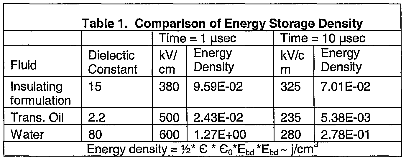
Claims
Priority Applications (4)
| Application Number | Priority Date | Filing Date | Title |
|---|---|---|---|
| CA2581701A CA2581701C (en) | 2004-08-20 | 2005-08-22 | Pulsed electric rock drilling, fracturing, and crushing methods and apparatus |
| AU2005277008A AU2005277008B2 (en) | 2004-08-20 | 2005-08-22 | Pulsed electric rock drilling, fracturing, and crushing methods and apparatus |
| EP05791498.8A EP1789652B1 (en) | 2004-08-20 | 2005-08-22 | Pulsed electric rock drilling, fracturing, and crushing methods and apparatus |
| EP19205048.2A EP3620605B1 (en) | 2004-08-20 | 2005-08-22 | Pulsed electric rock drilling, fracturing, and crushing methods and apparatus |
Applications Claiming Priority (10)
| Application Number | Priority Date | Filing Date | Title |
|---|---|---|---|
| US60350904P | 2004-08-20 | 2004-08-20 | |
| US60/603,509 | 2004-08-20 | ||
| US11/208,766 | 2005-08-19 | ||
| US11/208,579 US8083008B2 (en) | 2004-08-20 | 2005-08-19 | Pressure pulse fracturing system |
| US11/208,950 US7384009B2 (en) | 2004-08-20 | 2005-08-19 | Virtual electrode mineral particle disintegrator |
| US11/208,671 | 2005-08-19 | ||
| US11/208,766 US20060037516A1 (en) | 2004-08-20 | 2005-08-19 | High permittivity fluid |
| US11/208,579 | 2005-08-19 | ||
| US11/208,950 | 2005-08-19 | ||
| US11/208,671 US7416032B2 (en) | 2004-08-20 | 2005-08-19 | Pulsed electric rock drilling apparatus |
Publications (2)
| Publication Number | Publication Date |
|---|---|
| WO2006023998A2 true WO2006023998A2 (en) | 2006-03-02 |
| WO2006023998A3 WO2006023998A3 (en) | 2009-04-30 |
Family
ID=35968325
Family Applications (1)
| Application Number | Title | Priority Date | Filing Date |
|---|---|---|---|
| PCT/US2005/030178 WO2006023998A2 (en) | 2004-08-20 | 2005-08-22 | Pulsed electric rock drilling, fracturing, and crushing methods and apparatus |
Country Status (4)
| Country | Link |
|---|---|
| EP (2) | EP3620605B1 (en) |
| AU (1) | AU2005277008B2 (en) |
| CA (1) | CA2581701C (en) |
| WO (1) | WO2006023998A2 (en) |
Cited By (24)
| Publication number | Priority date | Publication date | Assignee | Title |
|---|---|---|---|---|
| US8628146B2 (en) | 2010-03-17 | 2014-01-14 | Auburn University | Method of and apparatus for plasma blasting |
| WO2016099271A1 (en) | 2014-12-19 | 2016-06-23 | Ihc Holland Ie B.V. | Device and method for crushing rock by means of pulsed electric energy |
| US9700893B2 (en) | 2004-08-20 | 2017-07-11 | Sdg, Llc | Virtual electrode mineral particle disintegrator |
| WO2017217992A1 (en) * | 2016-06-16 | 2017-12-21 | Halliburton Energy Services, Inc. | Drilling fluid for downhole electrocrushing drilling |
| US10012063B2 (en) | 2013-03-15 | 2018-07-03 | Chevron U.S.A. Inc. | Ring electrode device and method for generating high-pressure pulses |
| US10060195B2 (en) | 2006-06-29 | 2018-08-28 | Sdg Llc | Repetitive pulsed electric discharge apparatuses and methods of use |
| US10113364B2 (en) | 2013-09-23 | 2018-10-30 | Sdg Llc | Method and apparatus for isolating and switching lower voltage pulses from high voltage pulses in electrocrushing and electrohydraulic drills |
| US10370903B2 (en) | 2016-01-20 | 2019-08-06 | Baker Hughes, A Ge Company, Llc | Electrical pulse drill bit having spiral electrodes |
| US10407995B2 (en) | 2012-07-05 | 2019-09-10 | Sdg Llc | Repetitive pulsed electric discharge drills including downhole formation evaluation |
| US10435610B2 (en) | 2016-06-16 | 2019-10-08 | Halliburton Energy Services, Inc. | Drilling fluid for downhole electrocrushing drilling |
| US10557072B2 (en) | 2016-06-16 | 2020-02-11 | Halliburton Energy Services, Inc. | Drilling fluid for downhole electrocrushing drilling |
| US10557073B2 (en) | 2016-06-16 | 2020-02-11 | Halliburton Energy Services, Inc. | Drilling fluid for downhole electrocrushing drilling |
| US10717915B2 (en) | 2016-06-16 | 2020-07-21 | Halliburton Energy Services, Inc. | Drilling fluid for downhole electrocrushing drilling |
| US11078727B2 (en) | 2019-05-23 | 2021-08-03 | Halliburton Energy Services, Inc. | Downhole reconfiguration of pulsed-power drilling system components during pulsed drilling operations |
| WO2021206693A1 (en) * | 2020-04-06 | 2021-10-14 | Halliburton Energy Services, Inc. | Pulsed-power drill bit ground ring with variable outer diameter |
| WO2022047442A1 (en) * | 2020-08-28 | 2022-03-03 | Halliburton Energy Services, Inc. | Estimating formation isotopic concentration with pulsed power drilling |
| CN114658348A (en) * | 2022-03-30 | 2022-06-24 | 西安交通大学 | Shock wave rock breaking device, system and method, solid-liquid composite energetic material and preparation method |
| US11459883B2 (en) | 2020-08-28 | 2022-10-04 | Halliburton Energy Services, Inc. | Plasma chemistry derived formation rock evaluation for pulse power drilling |
| US11499421B2 (en) | 2020-08-28 | 2022-11-15 | Halliburton Energy Services, Inc. | Plasma chemistry based analysis and operations for pulse power drilling |
| US11525306B2 (en) | 2020-04-06 | 2022-12-13 | Halliburton Energy Services, Inc. | Pulsed-power drill bit ground ring with two portions |
| US11536136B2 (en) | 2020-08-28 | 2022-12-27 | Halliburton Energy Services, Inc. | Plasma chemistry based analysis and operations for pulse power drilling |
| SE2130178A1 (en) * | 2021-06-28 | 2022-12-29 | Epiroc Rock Drills Ab | A pulsed power drilling tool and a method for breaking a mineral substrate |
| US11585156B2 (en) | 2020-04-06 | 2023-02-21 | Halliburton Energy Services, Inc. | Pulsed-power drill bit ground ring with abrasive material |
| US11585743B2 (en) | 2020-08-28 | 2023-02-21 | Halliburton Energy Services, Inc. | Determining formation porosity and permeability |
Families Citing this family (1)
| Publication number | Priority date | Publication date | Assignee | Title |
|---|---|---|---|---|
| EP4112867A1 (en) * | 2021-07-02 | 2023-01-04 | Sandvik Mining and Construction Oy | Apparatus, drilling arrangement and method for high voltage electro pulse drilling |
Citations (1)
| Publication number | Priority date | Publication date | Assignee | Title |
|---|---|---|---|---|
| US6215734B1 (en) | 1996-08-05 | 2001-04-10 | Tetra Corporation | Electrohydraulic pressure wave projectors |
Family Cites Families (10)
| Publication number | Priority date | Publication date | Assignee | Title |
|---|---|---|---|---|
| US3158207A (en) * | 1961-08-14 | 1964-11-24 | Jersey Producttion Res Company | Combination roller cone and spark discharge drill bit |
| US3500942A (en) * | 1968-07-30 | 1970-03-17 | Shell Oil Co | Shaped spark drill |
| US3708022A (en) * | 1971-06-07 | 1973-01-02 | Trw Inc | Low voltage spark drill |
| AU554866B2 (en) | 1982-05-21 | 1986-09-04 | De Beers Industrial Diamond Division (Proprietary) Limited | High voltage disintegration |
| US4741405A (en) * | 1987-01-06 | 1988-05-03 | Tetra Corporation | Focused shock spark discharge drill using multiple electrodes |
| US5573307A (en) * | 1994-01-21 | 1996-11-12 | Maxwell Laboratories, Inc. | Method and apparatus for blasting hard rock |
| US5896938A (en) | 1995-12-01 | 1999-04-27 | Tetra Corporation | Portable electrohydraulic mining drill |
| EP0921270A4 (en) * | 1996-08-22 | 2000-11-08 | Komatsu Mfg Co Ltd | Underground augering machine by electrical crushing, excavator, and its excavating method |
| GB0203252D0 (en) * | 2002-02-12 | 2002-03-27 | Univ Strathclyde | Plasma channel drilling process |
| NO322323B2 (en) * | 2003-12-01 | 2016-09-13 | Unodrill As | Method and apparatus for ground drilling |
-
2005
- 2005-08-22 EP EP19205048.2A patent/EP3620605B1/en active Active
- 2005-08-22 EP EP05791498.8A patent/EP1789652B1/en active Active
- 2005-08-22 CA CA2581701A patent/CA2581701C/en active Active
- 2005-08-22 AU AU2005277008A patent/AU2005277008B2/en active Active
- 2005-08-22 WO PCT/US2005/030178 patent/WO2006023998A2/en active Application Filing
Patent Citations (1)
| Publication number | Priority date | Publication date | Assignee | Title |
|---|---|---|---|---|
| US6215734B1 (en) | 1996-08-05 | 2001-04-10 | Tetra Corporation | Electrohydraulic pressure wave projectors |
Cited By (35)
| Publication number | Priority date | Publication date | Assignee | Title |
|---|---|---|---|---|
| US9700893B2 (en) | 2004-08-20 | 2017-07-11 | Sdg, Llc | Virtual electrode mineral particle disintegrator |
| US10060195B2 (en) | 2006-06-29 | 2018-08-28 | Sdg Llc | Repetitive pulsed electric discharge apparatuses and methods of use |
| US8628146B2 (en) | 2010-03-17 | 2014-01-14 | Auburn University | Method of and apparatus for plasma blasting |
| US10407995B2 (en) | 2012-07-05 | 2019-09-10 | Sdg Llc | Repetitive pulsed electric discharge drills including downhole formation evaluation |
| US10012063B2 (en) | 2013-03-15 | 2018-07-03 | Chevron U.S.A. Inc. | Ring electrode device and method for generating high-pressure pulses |
| US10077644B2 (en) | 2013-03-15 | 2018-09-18 | Chevron U.S.A. Inc. | Method and apparatus for generating high-pressure pulses in a subterranean dielectric medium |
| US10113364B2 (en) | 2013-09-23 | 2018-10-30 | Sdg Llc | Method and apparatus for isolating and switching lower voltage pulses from high voltage pulses in electrocrushing and electrohydraulic drills |
| WO2016099271A1 (en) | 2014-12-19 | 2016-06-23 | Ihc Holland Ie B.V. | Device and method for crushing rock by means of pulsed electric energy |
| NL2014022B1 (en) * | 2014-12-19 | 2016-10-12 | Ihc Holland Ie Bv | Device and method for crushing rock by means of pulsed electric energy. |
| US10370903B2 (en) | 2016-01-20 | 2019-08-06 | Baker Hughes, A Ge Company, Llc | Electrical pulse drill bit having spiral electrodes |
| US11326086B2 (en) | 2016-06-16 | 2022-05-10 | Halliburton Energy Services, Inc. | Drilling fluid for downhole electrocrushing drilling |
| US11319475B2 (en) | 2016-06-16 | 2022-05-03 | Halliburton Energy Services, Inc. | Drilling fluid for downhole electrocrushing drilling |
| US10435610B2 (en) | 2016-06-16 | 2019-10-08 | Halliburton Energy Services, Inc. | Drilling fluid for downhole electrocrushing drilling |
| US10557072B2 (en) | 2016-06-16 | 2020-02-11 | Halliburton Energy Services, Inc. | Drilling fluid for downhole electrocrushing drilling |
| US10557073B2 (en) | 2016-06-16 | 2020-02-11 | Halliburton Energy Services, Inc. | Drilling fluid for downhole electrocrushing drilling |
| US10717915B2 (en) | 2016-06-16 | 2020-07-21 | Halliburton Energy Services, Inc. | Drilling fluid for downhole electrocrushing drilling |
| WO2017217992A1 (en) * | 2016-06-16 | 2017-12-21 | Halliburton Energy Services, Inc. | Drilling fluid for downhole electrocrushing drilling |
| US11091685B2 (en) | 2016-06-16 | 2021-08-17 | Halliburton Energy Services, Inc. | Drilling fluid for downhole electrocrushing drilling |
| US11091683B2 (en) | 2016-06-16 | 2021-08-17 | Halliburton Energy Services, Inc. | Drilling fluid for downhole electrocrushing drilling |
| US10316237B2 (en) | 2016-06-16 | 2019-06-11 | Halliburton Energy Services, Inc. | Drilling fluid for downhole electrocrushing drilling |
| US11326399B2 (en) | 2019-05-23 | 2022-05-10 | Halliburton Energy Services, Inc. | Downhole reconfiguration of pulsed-power drilling system components during pulsed drilling operations |
| US11078727B2 (en) | 2019-05-23 | 2021-08-03 | Halliburton Energy Services, Inc. | Downhole reconfiguration of pulsed-power drilling system components during pulsed drilling operations |
| US11525306B2 (en) | 2020-04-06 | 2022-12-13 | Halliburton Energy Services, Inc. | Pulsed-power drill bit ground ring with two portions |
| US11225836B2 (en) | 2020-04-06 | 2022-01-18 | Halliburton Energy Services, Inc. | Pulsed-power drill bit ground ring with variable outer diameter |
| WO2021206693A1 (en) * | 2020-04-06 | 2021-10-14 | Halliburton Energy Services, Inc. | Pulsed-power drill bit ground ring with variable outer diameter |
| US11585156B2 (en) | 2020-04-06 | 2023-02-21 | Halliburton Energy Services, Inc. | Pulsed-power drill bit ground ring with abrasive material |
| US11499421B2 (en) | 2020-08-28 | 2022-11-15 | Halliburton Energy Services, Inc. | Plasma chemistry based analysis and operations for pulse power drilling |
| WO2022047442A1 (en) * | 2020-08-28 | 2022-03-03 | Halliburton Energy Services, Inc. | Estimating formation isotopic concentration with pulsed power drilling |
| US11459883B2 (en) | 2020-08-28 | 2022-10-04 | Halliburton Energy Services, Inc. | Plasma chemistry derived formation rock evaluation for pulse power drilling |
| US11536136B2 (en) | 2020-08-28 | 2022-12-27 | Halliburton Energy Services, Inc. | Plasma chemistry based analysis and operations for pulse power drilling |
| US11585743B2 (en) | 2020-08-28 | 2023-02-21 | Halliburton Energy Services, Inc. | Determining formation porosity and permeability |
| US11619129B2 (en) | 2020-08-28 | 2023-04-04 | Halliburton Energy Services, Inc. | Estimating formation isotopic concentration with pulsed power drilling |
| SE2130178A1 (en) * | 2021-06-28 | 2022-12-29 | Epiroc Rock Drills Ab | A pulsed power drilling tool and a method for breaking a mineral substrate |
| SE544950C2 (en) * | 2021-06-28 | 2023-02-07 | Epiroc Rock Drills Ab | A pulsed power drilling tool and a method for breaking a mineral substrate |
| CN114658348A (en) * | 2022-03-30 | 2022-06-24 | 西安交通大学 | Shock wave rock breaking device, system and method, solid-liquid composite energetic material and preparation method |
Also Published As
| Publication number | Publication date |
|---|---|
| WO2006023998A3 (en) | 2009-04-30 |
| EP3620605A2 (en) | 2020-03-11 |
| EP1789652A4 (en) | 2012-05-30 |
| EP1789652A2 (en) | 2007-05-30 |
| EP3620605B1 (en) | 2022-08-24 |
| EP1789652B1 (en) | 2019-11-20 |
| CA2581701A1 (en) | 2006-03-02 |
| AU2005277008B2 (en) | 2011-10-06 |
| EP3620605A3 (en) | 2020-04-08 |
| AU2005277008A1 (en) | 2006-03-02 |
| CA2581701C (en) | 2013-10-08 |
Similar Documents
| Publication | Publication Date | Title |
|---|---|---|
| CA2581701C (en) | Pulsed electric rock drilling, fracturing, and crushing methods and apparatus | |
| US7530406B2 (en) | Method of drilling using pulsed electric drilling | |
| US9700893B2 (en) | Virtual electrode mineral particle disintegrator | |
| US7959094B2 (en) | Virtual electrode mineral particle disintegrator | |
| AU2009288327B2 (en) | Pulsed electric rock drilling apparatus with non-rotating bit and directional control | |
| US9190190B1 (en) | Method of providing a high permittivity fluid | |
| CA2873152C (en) | Virtual electrode mineral particle disintegrator | |
| CA2821140C (en) | Pulsed electric rock drilling, fracturing, and crushing methods and apparatus | |
| AU2013204846B2 (en) | Pulsed Electric Rock Drilling, Fracturing, and Crushing Methods and Apparatus |
Legal Events
| Date | Code | Title | Description |
|---|---|---|---|
| AK | Designated states |
Kind code of ref document: A2 Designated state(s): AE AG AL AM AT AU AZ BA BB BG BR BW BY BZ CA CH CN CO CR CU CZ DE DK DM DZ EC EE EG ES FI GB GD GE GH GM HR HU ID IL IN IS JP KE KG KM KP KR KZ LC LK LR LS LT LU LV MA MD MG MK MN MW MX MZ NA NG NI NO NZ OM PG PH PL PT RO RU SC SD SE SG SK SL SM SY TJ TM TN TR TT TZ UA UG US UZ VC VN YU ZA ZM ZW |
|
| AL | Designated countries for regional patents |
Kind code of ref document: A2 Designated state(s): BW GH GM KE LS MW MZ NA SD SL SZ TZ UG ZM ZW AM AZ BY KG KZ MD RU TJ TM AT BE BG CH CY CZ DE DK EE ES FI FR GB GR HU IE IS IT LT LU LV MC NL PL PT RO SE SI SK TR BF BJ CF CG CI CM GA GN GQ GW ML MR NE SN TD TG |
|
| 121 | Ep: the epo has been informed by wipo that ep was designated in this application | ||
| NENP | Non-entry into the national phase |
Ref country code: DE |
|
| WWE | Wipo information: entry into national phase |
Ref document number: 2005277008 Country of ref document: AU |
|
| WWE | Wipo information: entry into national phase |
Ref document number: 2005791498 Country of ref document: EP Ref document number: 2581701 Country of ref document: CA |
|
| ENP | Entry into the national phase |
Ref document number: 2005277008 Country of ref document: AU Date of ref document: 20050822 Kind code of ref document: A |
|
| WWP | Wipo information: published in national office |
Ref document number: 2005277008 Country of ref document: AU |
|
| WWP | Wipo information: published in national office |
Ref document number: 2005791498 Country of ref document: EP |