WO2005048469A2 - Wireless communication method and apparatus for implementing call admission control based on common measurements - Google Patents

Wireless communication method and apparatus for implementing call admission control based on common measurements Download PDF

Info

Publication number
WO2005048469A2
WO2005048469A2 PCT/US2004/037240 US2004037240W WO2005048469A2 WO 2005048469 A2 WO2005048469 A2 WO 2005048469A2 US 2004037240 W US2004037240 W US 2004037240W WO 2005048469 A2 WO2005048469 A2 WO 2005048469A2
Authority
WO
WIPO (PCT)
Prior art keywords
target cell
code
calculated
timeslot
cell
Prior art date
Application number
PCT/US2004/037240
Other languages
French (fr)
Other versions
WO2005048469A3 (en
Inventor
Christopher Cave
Original Assignee
Interdigital Technology Corporation
Priority date (The priority date is an assumption and is not a legal conclusion. Google has not performed a legal analysis and makes no representation as to the accuracy of the date listed.)
Filing date
Publication date
Application filed by Interdigital Technology Corporation filed Critical Interdigital Technology Corporation
Priority to MXPA06005007A priority Critical patent/MXPA06005007A/en
Priority to EP04810549A priority patent/EP1687904B1/en
Priority to DE602004014184T priority patent/DE602004014184D1/en
Priority to JP2006539717A priority patent/JP2007511180A/en
Priority to CA002544795A priority patent/CA2544795A1/en
Publication of WO2005048469A2 publication Critical patent/WO2005048469A2/en
Priority to NO20062524A priority patent/NO20062524L/en
Publication of WO2005048469A3 publication Critical patent/WO2005048469A3/en

Links

Classifications

    • HELECTRICITY
    • H04ELECTRIC COMMUNICATION TECHNIQUE
    • H04WWIRELESS COMMUNICATION NETWORKS
    • H04W28/00Network traffic management; Network resource management
    • H04W28/16Central resource management; Negotiation of resources or communication parameters, e.g. negotiating bandwidth or QoS [Quality of Service]
    • H04W28/18Negotiating wireless communication parameters
    • HELECTRICITY
    • H04ELECTRIC COMMUNICATION TECHNIQUE
    • H04BTRANSMISSION
    • H04B17/00Monitoring; Testing
    • H04B17/30Monitoring; Testing of propagation channels
    • H04B17/309Measuring or estimating channel quality parameters
    • H04B17/345Interference values
    • HELECTRICITY
    • H04ELECTRIC COMMUNICATION TECHNIQUE
    • H04BTRANSMISSION
    • H04B17/00Monitoring; Testing
    • H04B17/30Monitoring; Testing of propagation channels
    • H04B17/309Measuring or estimating channel quality parameters
    • H04B17/347Path loss
    • HELECTRICITY
    • H04ELECTRIC COMMUNICATION TECHNIQUE
    • H04JMULTIPLEX COMMUNICATION
    • H04J13/00Code division multiplex systems
    • H04J13/16Code allocation
    • HELECTRICITY
    • H04ELECTRIC COMMUNICATION TECHNIQUE
    • H04LTRANSMISSION OF DIGITAL INFORMATION, e.g. TELEGRAPHIC COMMUNICATION
    • H04L43/00Arrangements for monitoring or testing data switching networks
    • H04L43/08Monitoring or testing based on specific metrics, e.g. QoS, energy consumption or environmental parameters
    • H04L43/0876Network utilisation, e.g. volume of load or congestion level
    • HELECTRICITY
    • H04ELECTRIC COMMUNICATION TECHNIQUE
    • H04LTRANSMISSION OF DIGITAL INFORMATION, e.g. TELEGRAPHIC COMMUNICATION
    • H04L43/00Arrangements for monitoring or testing data switching networks
    • H04L43/16Threshold monitoring
    • HELECTRICITY
    • H04ELECTRIC COMMUNICATION TECHNIQUE
    • H04LTRANSMISSION OF DIGITAL INFORMATION, e.g. TELEGRAPHIC COMMUNICATION
    • H04L47/00Traffic control in data switching networks
    • H04L47/70Admission control; Resource allocation
    • H04L47/83Admission control; Resource allocation based on usage prediction

Definitions

  • the present invention is related to a wireless communication system. More particularly, the present invention is a method and apparatus for admission control based on common measurements performed in a wireless communication system.
  • a wireless transmit/receive unit communicates with a radio access network (RAN) via one or more radio channels which are established upon request from the WTRU or a core network.
  • RAN radio access network
  • a call admission control (CAC) process in a radio network controller (RNC) is invoked to process the request.
  • the CAC process determines whether or not a call should be admitted to the system. If the call is admitted, the CAC process determines the most efficient allocation of radio resources.
  • the CAC process In order to make such decisions, the CAC process must be aware of the state of the system at the time when the request is received. Power and interference measurements are typically used to characterize the current state of the system.
  • Measurements may be made by a Node-B or a WTRU. Measurements made by a Node-B may include uplink (UL) interference, downlink (DL) carrier power level, and/or DL code transmission power. Measurements made by a WTRU may include UL total transmission power level, UL code transmission power level, DL interference, and/or path loss. [0007] In many cases, measurements made by a WTRU are not available at the RNC. Thus, the CAC process must rely only on measurements made by a Node-B for admission control and resource allocation. Accordingly, a method and apparatus for implementing call admission control and resource allocation based only on measurements made by a Node-B is desired.
  • a method and apparatus for implementing call admission control based on Node-B measurements in a wireless communication system is disclosed.
  • the apparatus may be an integrated circuit (IC), Node-B or a wireless communication system.
  • a coverage area of the wireless communication system is divided into a plurality of cells and each cell is served by a Node-B.
  • a code is selected among available codes for potential allocation.
  • a target cell load and a neighbor cell load for each of the available timeslots is calculated assuming additional allocation of the selected code to each of the timeslots using Node-B measurements.
  • a weighted system load for the timeslot is calculated.
  • a timeslot having a smallest weighted system load is selected for allocation of the code.
  • Figure 1 is a flow diagram of a process including method steps for implementing CAC based on UL measurements in accordance with the present invention
  • Figure 2 is a flow diagram of a process including method steps for implementing CAC based on DL measurements in accordance with the present invention
  • Figure 3 is a diagram of a wireless communication system model in accordance with the present invention.
  • FIG. 4 is a block diagram of an apparatus used to implement
  • the features of the present invention may be incorporated into an integrated circuit (IC) or be configured in a circuit comprising a multitude of interconnecting components.
  • WTRU includes but is not limited to a user equipment, a mobile station, a fixed or mobile subscriber unit, a pager, or any other type of device capable of operating in a wireless environment.
  • Node-B includes but is not limited to a base station, a site controller, an access point or any other type of interfacing device in a wireless environment.
  • a CAC process of the present invention utilizes common measurements (i.e. measurements not dedicated to any specific radio link) made by a Node-B. The measurements may be either UL measurements or DL measurements.
  • the CAC process may utilize path loss information reported by a WTRU.
  • the UL measurement-based CAC process of the present invention uses a load metric of the target and neighboring cells in order to make a call admission decision and assign physical radio resources to the requested call.
  • ISCPpRED(i,t) ISCP(i, t) x R ⁇ (lSCP(i, t), A(i), SIR) ;
  • ISCP(i,t) a UL timeslot interference signal code power (ISCP) measurement measured by the Node-B
  • A(i) is a path loss to the target cell
  • SIR is a sum of the chip-level SIR targets of the added codes.
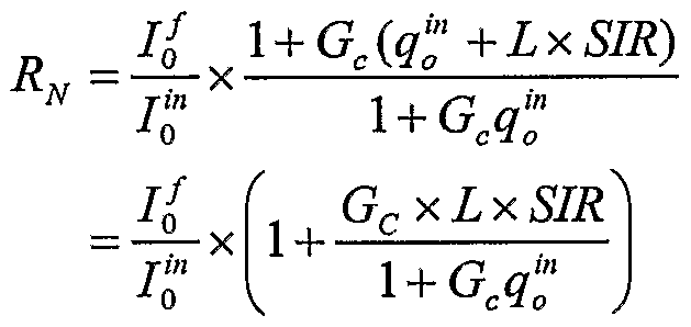
  • the noise rise function, RT is preferably given by: R ; (Equation 2) where ⁇ is a thermal noise level, L is a path loss, q is a load of the cell, and Gc is a link gain.
  • the CAC process of the present invention may operate using only the measurements made by the Node-B, and does not have to use a path loss measurement reported from a WTRU. However, if a path loss measurement reported by the WTRU is available, such as during a handover, the path loss measurement is used as an input to the noise rise function, RT. Otherwise, a path loss value parameter is used instead of a path loss measurement.
  • the path loss value parameter should be determined from the distribution of path losses measured throughout the cell through operation, administration and maintenance (OA&M). For example, the 50th percentile path loss for a given cell deployment may be used.
  • the estimated load, L(i,t) is used to evaluate the admission of the requested resource units in the timeslot.
  • the load of timeslot t in neighboring cell j is computed as follows: (Equation 4) for all j ⁇ i .
  • the current ISCP measurement of Node B j is available to the target cell and used as an input for the load computation.
  • the resulting load, L(j,t) is used to evaluate the admission of the requested resource units in the timeslot.
  • the load of timeslot t in neighboring cell j may be computed using the noise rise in neighboring cell j .
  • the allocation of a code(s) to a timeslot must satisfy WTRU capability requirements; otherwise, the allocation of the set of codes is rejected.
  • the UMTS standard defines a plurality of different classes of WTRUs. Each class is defined by a different set of capabilities.
  • One of the capability requirements of a WTRU is the number of codes that the WTRU supports in a single timeslot, as well as the number of different timeslots the WTRU can simultaneously support. The lower class WTRUs support less codes per timeslot, whereas the higher class WTRUs support more codes per timeslot.
  • a Node-B is aware of the WTRU class and hence, of the WTRU's capabilities in terms of the number of supported codes per timeslot and the number of supported timeslots. Therefore, before actually allocating codes to a particular WTRU in a given timeslot, it should be confirmed that the WTRU can handle the number of allocated codes in the timeslot.
  • FIG. 1 is a flow diagram of a process 100 including method steps for implementing CAC based on UL measurements in accordance with the present invention.
  • a code is selected from a list of available code sets (step 102).
  • the selected code is preferably the code with the smallest spreading factor (SF) in the code set.
  • a first timeslot is also selected for potential allocation amongst available timeslots (step 104).
  • the set of available timeslots consists of all timeslots that are available for the requested service type, (e.g., real time (RT) or non-real time (NRT)), and direction, (i.e., UL or DL).
  • the set of available timeslots is set through OA&M.
  • Equation 3 The process computes a target cell load and a neighboring cell load for the selected timeslot assuming the selected code is added to the selected timeslot in accordance with Equation 3 and Equation 4 (or alternatively, Equation 6) (step 106).
  • the load computation considers all codes from the code set that have already been allocated to the selected timeslot.
  • the process 100 then verifies CAC by determining whether the estimated target cell load and a neighboring cell load are below predetermined thresholds, respectively (step 108). If either the estimated target cell load or the estimated neighboring cell load is not below the thresholds, the code is not added to the timeslot for allocation, and the process proceeds to step 114. If both the estimated target cell load and the estimated neighboring cell load are below the thresholds, the selected code is added to the timeslot, at which point the timeslot becomes a candidate timeslot for potential allocation of the selected code and is added to a list of candidate timeslots (step 110). Once the code is added to the timeslot, a weighted system load is computed for the timeslot at step 112 as follows:
  • the next timeslot is selected from the list of available timeslots (step 116), and the process 100 returns to step 106.
  • the process 100 determines whether there are any candidate timeslots (step 118). If there are no candidate timeslots, the process 100 indicates a failure of allocation of resources and rejects the requested code set (step 130). If there are candidate timeslots, a timeslot having a smallest weighted system load, SYSTEM ) j s selected thereby resulting in allocation of the selected code in the selected candidate timeslot (step 120).
  • the allocated code is removed from a list of available code sets (step 122), and a list of candidate timeslots is reset (step 124).
  • the DL measurement-based CAC process of the present invention uses a transmit carrier power of the target cell and neighboring cells in order to make an admission decision and assign physical resources to a requested call.
  • the DL ISCP is predicted using carrier powers of neighboring cells.
  • the information about carrier transmission powers of neighboring cells is available to a target cell. However, the information about a path loss from the WTRU to neighboring cells is not available to the target cell. Therefore, the DL ISCP is estimated as follows:
  • X 2 is a random variable corresponding to a link gain between the WTRU and a neighboring tier 2 cell Node B
  • ⁇ x and ⁇ 2 represent the mean link gains between the WTRU located in the target cell and the Node Bs serving tier 1 and tier 2 cells.
  • the mean link gains are cell deployment-specific parameters which are set through OA&M.
  • the WTRU path loss measurement is available to the target cell, such as during a handover, the WTRU path loss measurement is used as an input for calculating the target cell noise rise function. Otherwise, a path loss value parameter is used, which is set through OA&M. The path loss value parameter should be determined from the distribution of path losses measured throughout the target cell.
  • the carrier power resulting from the addition of one or multiple codes in timeslot t of cell i is predicted as follows: A(i) x SIR ;
  • Equation 13 where A( ⁇ ) and SIR represent respectively the path loss to the target cell and the sum of the chip-level SIR targets of the added codes.
  • the increase of interference resulting from the addition of the code is applied to existing codes as well. This is achieved by multiplying the current transmission power by the noise rise.
  • the resulting predicted carrier transmission power, P PRED (i,t) is expressed in Watts.
  • Equation 14 Equation 16 is replaced by: (l01og 10 (R ⁇ £D (7,t))- ; ,) ⁇ P T MAX . (Equation 17)
  • the allocation of the set of codes must satisfy WTRU capability requirements; otherwise, the allocation of the set of codes is rejected.
  • FIG. 2 is a flow diagram of a process 200 including method steps for implementing CAC based on DL measurements in accordance with the present invention.
  • a code is selected from a list of available code sets (step 202).
  • 3GPP third generation partnership project
  • SF spreading factor
  • a first timeslot is also selected for potential allocation amongst available timeslots (step 204).
  • the set of available timeslots consists of all timeslots that are available for the requested service type, (e.g., RT or NRT), and direction, (i.e., UL or DL).
  • the set of available timeslots is set through OA&M.
  • the process 200 computes a predicted interference level and carrier transmission power of a target cell and a predicted interference level and carrier transmission power of neighboring cells for the selected timeslot assuming the selected code is added to the selected timeslot in accordance with Equation 12 and Equation 13 (or alternatively, Equation 14) (step 206). In Equations 12 and 13, the computation considers all codes from the code set that have already been allocated to the selected timeslot. [0043] The process 200 then verifies admission control by determining whether the estimated target cell carrier transmission power and a neighboring cell carrier transmission power are below predetermined thresholds, respectively (step 208).
  • the selected code is added to the timeslot, at which point the timeslot becomes a candidate timeslot for potential allocation of the selected code and is added to a list of candidate timeslots (step 210). If either the estimated target cell carrier transmission power or the estimated neighboring cell carrier transmission power is not below the thresholds, the code is not added to the timeslot for allocation, and the process proceeds to step 214.
  • a weighted interference level is computed for the timeslot at step 212 as follows: rPRED (j f 1 + rN t) . (Equation 18)
  • the denominator, i - + ⁇ . i) ⁇ is a fragmentation adjustment factor, where ⁇ corresponds to the fragmentation adjustment parameter and ⁇ ' corresponds to the number of codes already assigned to this timeslot.
  • the process 200 determines whether there are any candidate timeslots (step 218). If there are no candidate timeslots, the process 200 indicates a failure of allocation of resources and rejects the requested code set (step 230). If there are candidate timeslots, a timeslot having a smallest weighted interference level, 1 DL ⁇ ⁇ ) j s selected thereby resulting in allocation of the selected code in the selected candidate timeslot (step 220). The allocated code is removed from a list of available code sets (step 222), and a list of candidate timeslots is reset (step 224).
  • step 226 the process 200 indicates a successful allocation of resources and returns a resource assignment solution for the call request.
  • Figure 3 is a diagram of a wireless communication system model 300 in accordance with the present invention. There are a total of N + 1 cells CO-CN and the number of WTRUs mii-miN in cell Ci is N, + 1. The
  • WTRUs mii-m.iN served by cell Ci are denoted by ⁇ mij ⁇ .
  • the analysis presented hereinafter applies for both UL and DL.
  • I y is an interference level seen by WTRU m j (for DL) or by a
  • Node-B serving WTRU mj (for UL).
  • This power is transmitted either by the WTRU mij (in case of UL) or by its serving Node-B (in case of DL).
  • the load g, of cell Ci is defined as follows:
  • Equation 22 can be re-written as follows:
  • Equation 23 can be re-written as follows:
  • Equation (32) can be rewritten as: (Equation 33)
  • Equation 33 can be simplified to:
  • FIG. 4 is a block diagram of an apparatus 400 used to implement CAC in accordance with the present invention.
  • the apparatus 400 communicates with a core network 420 and a WTRU 430, and may reside in an RNC or a Node-B, or any other network entity which is responsible for CAC and radio resource allocation.
  • the apparatus 400 includes a receiver 402, a code selector 404, a first calculation unit 406, a comparator 408, a second calculation unit 410, and a controller 412.
  • the controller 412 initiates a CAC process in accordance with the present invention.
  • the code selector 404 selects a code among available codes in response to the controller 412. The selected code is evaluated for potential allocation to each of available timeslots through calculation of an estimated target cell load and neighbor cell loads based on UL interference, or through calculation of an estimated target cell transmission power and neighbor cell transmission power based on DL interference.
  • the first calculation unit 406 calculates a target cell load and a neighbor cell load for each available timeslot using Node-B measurements and assuming addition of the selected code.
  • the comparator 408 compares the target cell load and the neighbor cell load with predetermined thresholds, respectively. If both the target cell load and the neighbor cell load are below the thresholds, respectively, the code is added to the timeslot for potential allocation.
  • the second calculation unit 410 calculates a weighted system load for the timeslot.
  • the controller 412 controls the overall process and selects a timeslot having a smallest weighted system load among candidate timeslots to allocate for the call request.
  • the first calculation unit If the CAC is based on DL interference, the first calculation unit
  • the 406 calculates a target cell transmission power and a neighbor cell transmission power for each available timeslot using Node-B measurements and assuming addition of the selected code.
  • the comparator 408 compares the target cell transmission power and the neighbor cell transmission power with predetermined thresholds, respectively. If both the target cell transmission power and the neighbor cell transmission power are below the thresholds, respectively, the code is added to the timeslot for potential allocation.
  • the second calculation unit 410 calculates a weighted interference for the timeslot.
  • the controller 412 selects a timeslot having a smallest weighted interference among candidate timeslots to allocate for the call request. It is noted that the functions performed by the components with the apparatus 400 may be performed by more or less components as desired.

Abstract

A method and apparatus for admission control based on Node-B measurements in a wireless communication system is disclosed. Once a call request is received, a code is selected among available codes for potential allocation (102). A target cell load and a neighbor cell load for each of available timeslots is calculated assuming additional allocation of the selected code to each of the timeslots using Node-B measurements (106). A weighted system load for the timeslot is calculated (112). A timeslot having a smallest weighted system load is selected for allocation of the code (120).

Description

[0001] WIRELESS COMMUNICATION METHOD AND APPARATUS FOR IMPLEMENTING CALL ADMISSION CONTROL BASED ON COMMON MEASUREMENTS
[0002] FIELD OF INVENTION
[0003] The present invention is related to a wireless communication system. More particularly, the present invention is a method and apparatus for admission control based on common measurements performed in a wireless communication system.
[0004] BACKGROUND
[0005] In wireless communication systems, a wireless transmit/receive unit (WTRU) communicates with a radio access network (RAN) via one or more radio channels which are established upon request from the WTRU or a core network. Upon receiving a call request for radio resources, a call admission control (CAC) process in a radio network controller (RNC) is invoked to process the request. The CAC process determines whether or not a call should be admitted to the system. If the call is admitted, the CAC process determines the most efficient allocation of radio resources. [0006] In order to make such decisions, the CAC process must be aware of the state of the system at the time when the request is received. Power and interference measurements are typically used to characterize the current state of the system. Measurements may be made by a Node-B or a WTRU. Measurements made by a Node-B may include uplink (UL) interference, downlink (DL) carrier power level, and/or DL code transmission power. Measurements made by a WTRU may include UL total transmission power level, UL code transmission power level, DL interference, and/or path loss. [0007] In many cases, measurements made by a WTRU are not available at the RNC. Thus, the CAC process must rely only on measurements made by a Node-B for admission control and resource allocation. Accordingly, a method and apparatus for implementing call admission control and resource allocation based only on measurements made by a Node-B is desired.
[0008] SUMMARY
[0009] A method and apparatus for implementing call admission control based on Node-B measurements in a wireless communication system is disclosed. The apparatus may be an integrated circuit (IC), Node-B or a wireless communication system. A coverage area of the wireless communication system is divided into a plurality of cells and each cell is served by a Node-B. Once a call request is received, a code is selected among available codes for potential allocation. A target cell load and a neighbor cell load for each of the available timeslots is calculated assuming additional allocation of the selected code to each of the timeslots using Node-B measurements. A weighted system load for the timeslot is calculated. A timeslot having a smallest weighted system load is selected for allocation of the code.
[0010] BRIEF DESCRIPTION OF THE DRAWINGS
[0011] A more detailed understanding of the invention may be had from the following description of a preferred example, given by way of example and to be understood in conjunction with the accompanying drawing wherein:
[0012] Figure 1 is a flow diagram of a process including method steps for implementing CAC based on UL measurements in accordance with the present invention;
[0013] Figure 2 is a flow diagram of a process including method steps for implementing CAC based on DL measurements in accordance with the present invention;
[0014] Figure 3 is a diagram of a wireless communication system model in accordance with the present invention; and
[0015] Figure 4 is a block diagram of an apparatus used to implement
CAC in the system of Figure 3. [0016] DETAILED DESCRIPTION OF THE PREFERRED EMBODIMENTS [0017] The present invention will be explained, for simplicity, in the context of a universal mobile telephone system (UMTS). However, it should be noted that the present invention may be implemented in any type of wireless communication system based on hybrid time division multiple access (TDMA)-code division multiple access (CDMA).
[0018] The features of the present invention may be incorporated into an integrated circuit (IC) or be configured in a circuit comprising a multitude of interconnecting components.
[0019] Hereafter, the terminology "WTRU" includes but is not limited to a user equipment, a mobile station, a fixed or mobile subscriber unit, a pager, or any other type of device capable of operating in a wireless environment. When referred to hereafter, the terminology "Node-B" includes but is not limited to a base station, a site controller, an access point or any other type of interfacing device in a wireless environment. [0020] A CAC process of the present invention utilizes common measurements (i.e. measurements not dedicated to any specific radio link) made by a Node-B. The measurements may be either UL measurements or DL measurements. Optionally, the CAC process may utilize path loss information reported by a WTRU. When path loss information is available, the CAC process uses it. When path loss information is not available, a path loss parameter is used as an input, which will be explained hereinafter. [0021] The UL measurement-based CAC process of the present invention uses a load metric of the target and neighboring cells in order to make a call admission decision and assign physical radio resources to the requested call.
[0022] With respect to load computation for target cell(s), a predicted interference level, ISCPpRED(i,t), resulting from the addition of one or more codes in timeslot t of cell i is preferably predicted using a noise rise function of the target cell, RT. ISCPPRED (i, t) = ISCP(i, t) x Rτ (lSCP(i, t), A(i), SIR) ; (Equation 1) where ISCP(i,t) is a UL timeslot interference signal code power (ISCP) measurement measured by the Node-B, A(i) is a path loss to the target cell, and SIR is a sum of the chip-level SIR targets of the added codes. The noise rise function, RT is preferably given by: R ; (Equation 2)
Figure imgf000006_0001
where θ is a thermal noise level, L is a path loss, q is a load of the cell, and Gc is a link gain.
[0023] The CAC process of the present invention may operate using only the measurements made by the Node-B, and does not have to use a path loss measurement reported from a WTRU. However, if a path loss measurement reported by the WTRU is available, such as during a handover, the path loss measurement is used as an input to the noise rise function, RT. Otherwise, a path loss value parameter is used instead of a path loss measurement. The path loss value parameter should be determined from the distribution of path losses measured throughout the cell through operation, administration and maintenance (OA&M). For example, the 50th percentile path loss for a given cell deployment may be used.
[0024] The estimated load in a particular timeslot t of cell i is preferably computed as follows: L(i, 0 = 1 N° ; (Equation 3) ISCPPRED(i,t) where N0 represents the receiver noise level. The estimated load, L(i,t) , is used to evaluate the admission of the requested resource units in the timeslot. [0025] With respect to load computation for neighboring cells, the load of timeslot t in neighboring cell j is computed as follows:
Figure imgf000006_0002
(Equation 4) for all j ≠ i . The current ISCP measurement of Node B j is available to the target cell and used as an input for the load computation. The resulting load, L(j,t) , is used to evaluate the admission of the requested resource units in the timeslot.
[0026] In an alternate embodiment, the load of timeslot t in neighboring cell j may be computed using the noise rise in neighboring cell j . In this embodiment, a noise rise function of neighboring cells may be estimated using a noise rise function of the target cell to estimate the increase of interference in neighboring cells assuming a code(s) is assigned thereto as follows: RN = RT(\ + Gc x A(i) x SIR); (Equation 5) where Rτ is given in Equation 2, Gc is a calibration parameter, A(i) represents the path loss to the target cell and SIR is the sum of the chip- level SIR targets of the added codes. The derivation of a noise rise function of neighboring cells from a noise rise function of a target cell is explained in more detail with reference to Figure 3. In this embodiment, Equation 4 is replaced with: L(j, Λ = l ^ . (Equation 6) ISCP(j,t) χ RN
[0027] The allocation of one or more codes in timeslot t of cell i is accepted if and only if the following conditions are satisfied: L(i, t) < LTMAX ; and (Equation 7) L(j, t) < LNMAX ; (Equation 8) for all neighboring cells j under consideration. L(i,t) and L(j,t) are computed as described in Equation 3 and Equation 4 (or alternatively, Equation 6), respectively. LTMAX and LNMAX represent the load thresholds for the target cell and neighboring cells.
[0028] It is noted that the allocation of a code(s) to a timeslot must satisfy WTRU capability requirements; otherwise, the allocation of the set of codes is rejected. For example, the UMTS standard defines a plurality of different classes of WTRUs. Each class is defined by a different set of capabilities. One of the capability requirements of a WTRU is the number of codes that the WTRU supports in a single timeslot, as well as the number of different timeslots the WTRU can simultaneously support. The lower class WTRUs support less codes per timeslot, whereas the higher class WTRUs support more codes per timeslot. A Node-B is aware of the WTRU class and hence, of the WTRU's capabilities in terms of the number of supported codes per timeslot and the number of supported timeslots. Therefore, before actually allocating codes to a particular WTRU in a given timeslot, it should be confirmed that the WTRU can handle the number of allocated codes in the timeslot.
[0029] Figure 1 is a flow diagram of a process 100 including method steps for implementing CAC based on UL measurements in accordance with the present invention. When a wireless communication system receives a call request for a WTRU, a code is selected from a list of available code sets (step 102). The selected code is preferably the code with the smallest spreading factor (SF) in the code set. A first timeslot is also selected for potential allocation amongst available timeslots (step 104). The set of available timeslots consists of all timeslots that are available for the requested service type, (e.g., real time (RT) or non-real time (NRT)), and direction, (i.e., UL or DL). The set of available timeslots is set through OA&M. [0030] The process computes a target cell load and a neighboring cell load for the selected timeslot assuming the selected code is added to the selected timeslot in accordance with Equation 3 and Equation 4 (or alternatively, Equation 6) (step 106). In Equation 3, the load computation considers all codes from the code set that have already been allocated to the selected timeslot.
[0031] The process 100 then verifies CAC by determining whether the estimated target cell load and a neighboring cell load are below predetermined thresholds, respectively (step 108). If either the estimated target cell load or the estimated neighboring cell load is not below the thresholds, the code is not added to the timeslot for allocation, and the process proceeds to step 114. If both the estimated target cell load and the estimated neighboring cell load are below the thresholds, the selected code is added to the timeslot, at which point the timeslot becomes a candidate timeslot for potential allocation of the selected code and is added to a list of candidate timeslots (step 110). Once the code is added to the timeslot, a weighted system load is computed for the timeslot at step 112 as follows:
L(i, t) + ∑ c λL(j, t) + ∑ a2L(j, t) ^ T SYSTEM ( VΛ ) - — t 1 , ΛrΛΛ l + N(t) ; (Equation 9) where i and 2 define respectively the set of tier one and tier two neighboring cells to be included in the overall system load. a\ and a"1 represent weighting factors to be applied to tier one and tier two cell loads.
The denominator, l + 7 Λ'( j is a fragmentation adjustment factor, where W corresponds to the fragmentation adjustment parameter and ^> corresponds to the number of codes already assigned to the timeslot. Once the weighted system load has been computed, the process 100 proceeds to step 114. [0032] If it is determined that there are more available timeslots at step
114, the next timeslot is selected from the list of available timeslots (step 116), and the process 100 returns to step 106. If there are no available timeslots for computing a weighted system load, the process 100 determines whether there are any candidate timeslots (step 118). If there are no candidate timeslots, the process 100 indicates a failure of allocation of resources and rejects the requested code set (step 130). If there are candidate timeslots, a timeslot having a smallest weighted system load, SYSTEM ) js selected thereby resulting in allocation of the selected code in the selected candidate timeslot (step 120). The allocated code is removed from a list of available code sets (step 122), and a list of candidate timeslots is reset (step 124). If there are more available codes in a code set, as determined in step 126, the process 100 returns to step 102. If not, the process 100 proceeds to step 128 where the process 100 indicates a successful allocation of resources and returns a resource assignment solution for the call request (step 128). [0033] The DL measurement-based CAC process of the present invention uses a transmit carrier power of the target cell and neighboring cells in order to make an admission decision and assign physical resources to a requested call. The DL ISCP is predicted using carrier powers of neighboring cells. The DL ISCP in timeslot tof a WTRU located in cell i , IDL(i,t) , can be expressed according to: IDL (i,t) = N0 (Equation 10)
Figure imgf000010_0001
where N0 represents a receiver noise level, A(j) represents a path loss between a WTRU and a cell j , and Pτ(j,t) represents a total DL transmit power of cell j in timeslot t . All quantities are expressed using a linear scale. 3[ and 32 define respectively the set of tier one and tier two neighboring cells to be included in the interference prediction. The information about carrier transmission powers of neighboring cells is available to a target cell. However, the information about a path loss from the WTRU to neighboring cells is not available to the target cell. Therefore, the DL ISCP is estimated as follows:
E[lDL(i,t)] = N0 + ∑E[Xl]Pτ(j,t)+ ∑ f2]Pr(./,t) e3' ye32 ; (Equation 11) = N0 + μ1
Figure imgf000010_0002
where Xl is a random variable corresponding to a link gain (i.e. inverse of a path loss) between the WTRU and a neighboring tier 1 cell Node B, X2 is a random variable corresponding to a link gain between the WTRU and a neighboring tier 2 cell Node B, and μx and μ2 represent the mean link gains between the WTRU located in the target cell and the Node Bs serving tier 1 and tier 2 cells. The mean link gains are cell deployment-specific parameters which are set through OA&M. [0034] Once the expected interference level is calculated, the interference resulting from the addition of one or multiple codes in timeslot t of cell i is predicted as follows using the noise rise function of the target cell described in Equation 2: 7™ D(i,t) = E[lDL(i,t)]x RT{E[lDL(i,t)\A(i),SIR); (Equation 12) where A(i) represents a path loss to the target cell and SIR represents a sum of the chip-level SIR targets of the added codes.
[0035] If the WTRU path loss measurement is available to the target cell, such as during a handover, the WTRU path loss measurement is used as an input for calculating the target cell noise rise function. Otherwise, a path loss value parameter is used, which is set through OA&M. The path loss value parameter should be determined from the distribution of path losses measured throughout the target cell.
[0036] The carrier power resulting from the addition of one or multiple codes in timeslot t of cell i is predicted as follows:
Figure imgf000011_0001
A(i) x SIR ;
(Equation 13) where A(ϊ) and SIR represent respectively the path loss to the target cell and the sum of the chip-level SIR targets of the added codes. The increase of interference resulting from the addition of the code is applied to existing codes as well. This is achieved by multiplying the current transmission power by the noise rise. The resulting predicted carrier transmission power, PPRED(i,t) , is expressed in Watts.
[0037] In an alternate embodiment, the carrier power in neighboring cells can be predicted according to: PT PRED U, t) = Pτ (j, t) χ RN; (Equation 14) where RN is calculated according to Equation 5.
[0038] The allocation of a set of codes in timeslot t of cell i is accepted if and only if the following conditions are satisfied: (lO\og10(pT PRED(i,t))-MT)< PT MAX; and (Equation 15) (l01og10( rC/,t))- < PT MAX ; (Equation 16) for all neighboring cells j under consideration. Pr PΛ£β(f,t) is computed as described in Equation 13. Mτ and MN represent respectively CAC power margins for the target and neighbor cells. P^ corresponds to the maximum Node-B timeslot carrier power, expressed in dB, which is set through OA&M. [0039] If the carrier power is predicted in neighboring cells according to
Equation 14, then Equation 16 is replaced by: (l01og10(R Λ£D(7,t))- ;,)< PT MAX . (Equation 17)
[0040] Moreover, the allocation of the set of codes must satisfy WTRU capability requirements; otherwise, the allocation of the set of codes is rejected.
[0041] Figure 2 is a flow diagram of a process 200 including method steps for implementing CAC based on DL measurements in accordance with the present invention. When a wireless communication system receives a call request for a WTRU, a code is selected from a list of available code sets (step 202). Under the current third generation partnership project (3GPP), only SF 16 codes are used for DL. However, other SF codes may be used for DL. Thus, a code may be selected, starting from a code having a smallest spreading factor (SF) in the code set. A first timeslot is also selected for potential allocation amongst available timeslots (step 204). The set of available timeslots consists of all timeslots that are available for the requested service type, (e.g., RT or NRT), and direction, (i.e., UL or DL). The set of available timeslots is set through OA&M.
[0042] The process 200 computes a predicted interference level and carrier transmission power of a target cell and a predicted interference level and carrier transmission power of neighboring cells for the selected timeslot assuming the selected code is added to the selected timeslot in accordance with Equation 12 and Equation 13 (or alternatively, Equation 14) (step 206). In Equations 12 and 13, the computation considers all codes from the code set that have already been allocated to the selected timeslot. [0043] The process 200 then verifies admission control by determining whether the estimated target cell carrier transmission power and a neighboring cell carrier transmission power are below predetermined thresholds, respectively (step 208). If both the estimated target cell carrier transmission power and the estimated neighboring cell carrier transmission power are below the thresholds, the selected code is added to the timeslot, at which point the timeslot becomes a candidate timeslot for potential allocation of the selected code and is added to a list of candidate timeslots (step 210). If either the estimated target cell carrier transmission power or the estimated neighboring cell carrier transmission power is not below the thresholds, the code is not added to the timeslot for allocation, and the process proceeds to step 214.
[0044] Once the code is added to the timeslot, a weighted interference level is computed for the timeslot at step 212 as follows: rPRED (j f 1 + rN t) . (Equation 18)
The denominator, i- + ^ .i) } is a fragmentation adjustment factor, where λ corresponds to the fragmentation adjustment parameter and ^ ' corresponds to the number of codes already assigned to this timeslot.
[0045] If it is determined that there are more available timeslots at step
214, the next timeslot is selected from the list of available timeslots (step 216), and steps 202-214 are repeated. If there are no available timeslots for computing a weighted interference level, the process 200 determines whether there are any candidate timeslots (step 218). If there are no candidate timeslots, the process 200 indicates a failure of allocation of resources and rejects the requested code set (step 230). If there are candidate timeslots, a timeslot having a smallest weighted interference level, 1DL\ ^) js selected thereby resulting in allocation of the selected code in the selected candidate timeslot (step 220). The allocated code is removed from a list of available code sets (step 222), and a list of candidate timeslots is reset (step 224). If there are more codes in a code set, the process returns to step 202 for evaluation of each, code, and if not, the process proceeds to step 228 (step 226). In step 228, the process 200 indicates a successful allocation of resources and returns a resource assignment solution for the call request.
[0046] The derivation of the noise rise function for neighboring cells from a noise rise function of the target cell is explained in more detail with reference to Figure 3. Figure 3 is a diagram of a wireless communication system model 300 in accordance with the present invention. There are a total of N + 1 cells CO-CN and the number of WTRUs mii-miN in cell Ci is N, + 1. The
WTRUs mii-m.iN served by cell Ci are denoted by {mij}. The analysis presented hereinafter applies for both UL and DL.
[0047] Iy is an interference level seen by WTRU m j (for DL) or by a
Node-B serving WTRU mj (for UL). The required transmission power for serving a WTRU mij is equal to: Py = /„ SIRy Ly (Equation 19) where LtJ is a path loss between a cell Ci and a WTRU mij, and SIRy is a required signal-to-interference ratio to adequately serve the WTRU mij. This power is transmitted either by the WTRU mij (in case of UL) or by its serving Node-B (in case of DL). [0O48] Equation 19 can be re-written: Pυ = /„ qv (Equation 20) where qy a SIRy Ly is defined as the "load" of the WTRU my. The load g, of cell Ci is defined as follows:
1- Σ 1>j • (Equation 21)
[0O49] The interference level Iy can be calculated, for a system where same-cell WTRUs cause negligible interference, as follows: I.J = Θ + (Equation 22)
Figure imgf000015_0001
where θ is a thermal noise level, and ,, y is a path loss between the WTRU my and the cell C (for DL) or between the WTRU mrj' and the cell Ci (for UL). [0050] A link gain (inverse of a path loss) between a cell and a WTRU connected to another cell is equal to Gc .
Z = — if i'≠ i . (Equation 23) Gc
[0051] With this assumption, Equation 22 can be re-written as follows:
Iv I> • (Equation 24)
Figure imgf000015_0002
[0052] The right term is independent of j . Therefore, It ≡ I V/, and
Equation 23 can be re-written as follows:
I, Vi (Equation 25)
Figure imgf000015_0003
[0053] From this set of equations (valid for any cell C it is possible to express the interference of any cell, say cell Co, as a function of the loads qt of all cells and the constant Gc . This can be achieved by first considering
Equation 24 for i = 0 specifically: N I0 = θ + Gc∑ It.q,, - G 0q0 (Equation 26) ι'=0
[0054] Then, combining it with the general equation in i , the following equations are obtained: /, = /„ + Gc I0 qQ - Gc /, q, , or (Equation 27)
I = I0 1 + Ge q° Vi . (Equation 28) 1 + Ge q,
[0055] Let CQ represent the target cell to which codes are being allocated to and C, represent a neighboring cell. As such, the load q0 of C0 will change following the allocation of the codes. [0056] Let qg' represent the initial load of C0 , prior to the allocation of codes. Let qf represent the final load of C0 , following the allocation of codes. Then, q{ = q0'" ÷Lx SIR (Equation 29)
[0057] Equation 28 must be satisfied both prior to and following the allocation of codes to C ° . That is, /;" = / « — l + G ^c- q™0'n- V (Equation 30) 1 + Gc q, and // vi (Equation 31)
Figure imgf000016_0001
where I™ and l{ represent respectively the initial and final interference in target cell C0 , and I"1 and if represent respectively the initial and final interference in neighbor cell C, . n
[0058] The noise rise in neighbor cell ' is then given by:
R NN = jim- = ^ ri-n x i , f c^° in . ( sEq ^uation 32)
[0059] Equation (32) can be rewritten as: (Equation 33)
Figure imgf000016_0002
[0060] When the initial load of ° is unknown, Equation 33 can be simplified to:
^ =^ x (l + Gc x Ix SIR) (Equation 34) I" by setting q™ to zero, T corresponds to the noise rise calculated according to
Equation 2. [0061] Figure 4 is a block diagram of an apparatus 400 used to implement CAC in accordance with the present invention. The apparatus 400 communicates with a core network 420 and a WTRU 430, and may reside in an RNC or a Node-B, or any other network entity which is responsible for CAC and radio resource allocation.
[0062] The apparatus 400 includes a receiver 402, a code selector 404, a first calculation unit 406, a comparator 408, a second calculation unit 410, and a controller 412. Once a call request is received from the WTRU 430 or the core network 420, the controller 412 initiates a CAC process in accordance with the present invention. The code selector 404 selects a code among available codes in response to the controller 412. The selected code is evaluated for potential allocation to each of available timeslots through calculation of an estimated target cell load and neighbor cell loads based on UL interference, or through calculation of an estimated target cell transmission power and neighbor cell transmission power based on DL interference.
[0063] If the CAC process is based on UL interference, the first calculation unit 406 calculates a target cell load and a neighbor cell load for each available timeslot using Node-B measurements and assuming addition of the selected code. The comparator 408 compares the target cell load and the neighbor cell load with predetermined thresholds, respectively. If both the target cell load and the neighbor cell load are below the thresholds, respectively, the code is added to the timeslot for potential allocation. The second calculation unit 410 calculates a weighted system load for the timeslot. The controller 412 controls the overall process and selects a timeslot having a smallest weighted system load among candidate timeslots to allocate for the call request.
[0064] If the CAC is based on DL interference, the first calculation unit
406 calculates a target cell transmission power and a neighbor cell transmission power for each available timeslot using Node-B measurements and assuming addition of the selected code. The comparator 408 compares the target cell transmission power and the neighbor cell transmission power with predetermined thresholds, respectively. If both the target cell transmission power and the neighbor cell transmission power are below the thresholds, respectively, the code is added to the timeslot for potential allocation. The second calculation unit 410 calculates a weighted interference for the timeslot. The controller 412 selects a timeslot having a smallest weighted interference among candidate timeslots to allocate for the call request. It is noted that the functions performed by the components with the apparatus 400 may be performed by more or less components as desired.
[0065] Although the features and elements of the present invention are described in the preferred embodiments in particular combinations, each feature or element can be used alone without the other features and elements of the preferred embodiments or in various combinations with or without other features and elements of the present invention.

Claims

CLAIMS What is claimed is: 1. In a wireless communication system including at lease one Node-B and at least one wireless transmit/receive unit (WTRU), a method of implementing a call admission control process at a Node-B comprising: (a) receiving a call request; (b) selecting a particular code from a code set; (c) selecting a particular timeslot from a plurality of available timeslots; (d) calculating a target cell load and a neighbor cell load for the selected timeslot using Node-B measurements and assuming addition of the selected code to the selected timeslot; (e) calculating a weighted system load for the selected timeslot; (f) repeating steps (c)-(e) for all other available timeslots; (g) selecting a timeslot having a smallest weighted system load for allocation of the code; and (h) removing the code from the code set.
2. The method of claim 1 wherein the weighted system load is calculated only if both the target cell load and the neighbor cell load are below predetermined thresholds, respectively.
3. The method of claim 1 wherein the code is selected starting from a code having a smallest spreading factor.
4. The method of claim 1 wherein the target cell load is calculated using a predicted interference signal code power (ISCP) of the target cell.
5. The method of claim 4 wherein the predicted ISCP in the target cell is calculated using a noise rise function of the target cell.
6. The method of claim 5 wherein the noise rise function of the target cell is calculated using reported path loss measurements.
7. The method of claim 5 wherein the noise rise function of the target cell is calculated using a path loss value parameter determined from a distribution of path losses measured throughout the cell.
8. The method of claim 7 wherein the path loss value parameter is set to 50th percentile path loss of the distribution.
9. The method of claim 1 wherein the neighbor cell load is calculated using a ISCP measured by the neighbor cell.
10. The method of claim 1 wherein the neighbor cell load is estimated with a noise rise function of the target cell.
11. In a wireless communication system including at lease one Node-B and at least one wireless transmit/receive unit (WTRU), a method of implementing a call admission control process at a Node-B comprising: (a) receiving a call request; (b) selecting a particular code from a code set; (c) selecting a particular timeslot from a plurality of available timeslots; (d) calculating a predicted target cell transmission power and a predicted neighbor cell transmission power for the selected timeslot using Node-B measurements and assuming addition of the selected code to the selected timeslot; (e) calculating a weighted interference for the timeslot; (f) repeating steps (c)-(e) for all other available timeslots; (g) selecting a timeslot having a smallest weighted interference for allocation of the code; and (h) removing the code from the code set.
12. The method of claim 11 wherein the weighted interference is calculated only if both the predicted target cell transmission power and the predicted neighbor cell transmission power are below predetermined thresholds, respectively.
13. The method of claim 11 wherein the code is selected starting from a code having a smallest spreading factor.
14. The method of claim 11 wherein the predicted target cell transmission power is calculated using a predicted interference signal code power (ISCP) of the target cell.
15. The method of claim 14 wherein the predicted ISCP in the target cell is calculated using a noise rise function of the target cell.
16. The method of claim 15 wherein the noise rise function of the target cell is calculated using reported path loss measurements.
17. The method of claim 15 wherein the noise rise function of the target cell is calculated using a path loss value parameter determined from a distribution of path losses measured throughout the cell.
18. The method of claim 17 wherein the path loss value parameter is set to 50th percentile path loss of the distribution.
19. The method of claim 11 wherein the predicted neighbor cell transmission power is calculated using a transmission power measured by the neighbor cell.
20. The method of claim 11 wherein the predicted neighbor cell transmission power is estimated with a noise rise function of the target cell.
21. An apparatus for admission control based on common measurements of a Node-B in a wireless communication system, a coverage area of the wireless communication system being divided into a plurality of cells and each cell being served by at least one Node-B, the apparatus comprising: a receiver configured to receive a call request; a code selector configured to select a code among available codes; a first calculation unit configured to calculate a target cell load and a neighbor cell load for each available timeslot using Node-B measurements and assuming addition of the selected code, a second calculation unit for calculating a weighted system load for each of the available timeslots; and a controller for selecting a timeslot having a smallest weighted system load to allocate for the call request.
22. The apparatus of claim 21 further comprising a comparator for comparing the target cell load and the neighbor cell load of each available timeslot with predetermined thresholds, respectively, whereby the weighted interference is calculated for available timeslots satisfying the thresholds.
23. The apparatus of claim 21 wherein the code is selected starting from a code having a smallest spreading factor.
24. The apparatus of claim 21 wherein the target cell load is calculated using a predicted interference signal code power (ISCP) of the target cell.
25. The apparatus of claim 24 wherein the predicted ISCP in the target cell is calculated using a noise rise function of the target cell.
26. The apparatus of claim 25 wherein the noise rise function of the target cell is calculated using reported path loss measurements.
27. The apparatus of claim 25 wherein the noise rise function of the target cell is calculated using a path loss value parameter determined from a distribution of path losses measured throughout the cell.
28. The apparatus of claim 27 wherein the path loss value parameter is set to 50th percentile path loss of the distribution.
29. The apparatus of claim 21 wherein the neighbor cell load is calculated using a ISCP measured by the neighbor cell.
30. The apparatus of claim 21 wherein the neighbor cell load is estimated with a noise rise function of the target cell.
31. An apparatus for admission control based on common measurements of a Node-B in a wireless communication system, a coverage area of the wireless communication system being divided into a plurality of cells and each cell being served by at least one Node-B, the apparatus comprising: a receiver configured to receive a call request; a code selector configured to select a code among available codes; a first calculation unit for calculating a target cell transmission power and a neighbor cell transmission power for each available timeslot using Node-B measurements and assuming addition of the selected code; a second calculation unit for calculating a weighted interference for each of the selected timeslots; and a controller for selecting a timeslot having a smallest weighted interference among timeslots to allocate for the call request.
32. The apparatus of claim 31 further comprising a comparator for comparing the target cell transmission power and the neighbor cell transmission power of each available timeslot with predetermined thresholds, respectively, whereby the weighted interference is calculated for available timeslots satisfying the thresholds.
33. The apparatus of claim 31 wherein the code is selected starting from a code having a smallest spreading factor.
34. The apparatus of claim 31 wherein the predicted target cell transmission power is calculated using a predicted interference signal code power (ISCP) of the target cell.
35. The apparatus of claim 34 wherein the predicted ISCP in the target cell is calculated using a noise rise function of the target cell.
36. The apparatus of claim 35 wherein the noise rise function of the target cell is calculated using reported path loss measurements.
37. The apparatus of claim 36 wherein the noise rise function of the target cell is calculated using a path loss value parameter determined from a distribution of path losses measured throughout the cell.
38. The apparatus of claim 37 wherein the path loss value parameter is set to 50th percentile path loss of the distribution.
39. The apparatus of claim 31 wherein the predicted neighbor cell transmission power is calculated using a transmission power measured by the neighbor cell.
40. The apparatus of claim 31 wherein the predicted neighbor cell transmission power is estimated with a noise rise function of the target cell.
PCT/US2004/037240 2003-11-07 2004-11-05 Wireless communication method and apparatus for implementing call admission control based on common measurements WO2005048469A2 (en)

Priority Applications (6)

Application Number Priority Date Filing Date Title
MXPA06005007A MXPA06005007A (en) 2003-11-07 2004-11-05 Wireless communication method and apparatus for implementing call admission control based on common measurements.
EP04810549A EP1687904B1 (en) 2003-11-07 2004-11-05 Wireless communication method and apparatus for implementing call admission control based on common measurements
DE602004014184T DE602004014184D1 (en) 2003-11-07 2004-11-05 WIRELESS COMMUNICATION PROCESS AND DEVICE RELATING TO COMMON MEASUREMENTS
JP2006539717A JP2007511180A (en) 2003-11-07 2004-11-05 Wireless communication method and apparatus for performing call admission control based on common measurements
CA002544795A CA2544795A1 (en) 2003-11-07 2004-11-05 Wireless communication method and apparatus for implementing call admission control based on common measurements
NO20062524A NO20062524L (en) 2003-11-07 2006-06-01 Tradlos communication method and apparatus for implementing call access control based on common measurements

Applications Claiming Priority (2)

Application Number Priority Date Filing Date Title
US51838003P 2003-11-07 2003-11-07
US60/518,380 2003-11-07

Publications (2)

Publication Number Publication Date
WO2005048469A2 true WO2005048469A2 (en) 2005-05-26
WO2005048469A3 WO2005048469A3 (en) 2006-08-03

Family

ID=34590254

Family Applications (1)

Application Number Title Priority Date Filing Date
PCT/US2004/037240 WO2005048469A2 (en) 2003-11-07 2004-11-05 Wireless communication method and apparatus for implementing call admission control based on common measurements

Country Status (14)

Country Link
US (1) US20050117533A1 (en)
EP (1) EP1687904B1 (en)
JP (1) JP2007511180A (en)
KR (2) KR20060095778A (en)
CN (1) CN1985450A (en)
AR (1) AR046444A1 (en)
AT (1) ATE397331T1 (en)
CA (1) CA2544795A1 (en)
DE (1) DE602004014184D1 (en)
ES (1) ES2305898T3 (en)
MX (1) MXPA06005007A (en)
NO (1) NO20062524L (en)
TW (2) TW200623919A (en)
WO (1) WO2005048469A2 (en)

Cited By (2)

* Cited by examiner, † Cited by third party
Publication number Priority date Publication date Assignee Title
EP2181515A1 (en) * 2007-08-23 2010-05-05 Telefonaktiebolaget LM Ericsson (PUBL) Code assignment in hs-scch less operation mode
EP2989818A1 (en) * 2013-04-25 2016-03-02 Nokia Solutions and Networks Oy Area/cell availability evaluation

Families Citing this family (7)

* Cited by examiner, † Cited by third party
Publication number Priority date Publication date Assignee Title
GB2445393A (en) * 2006-12-05 2008-07-09 Roke Manor Research Call admission control in a cdma communication system
US8224326B1 (en) * 2007-03-19 2012-07-17 At&T Mobility Ii Llc GSM rescue handover utilizing adaptive multirate half-rate
US8218450B2 (en) * 2007-05-24 2012-07-10 Nec Corporation Throughput estimation method and system
KR101048456B1 (en) * 2007-10-16 2011-07-11 삼성전자주식회사 Apparatus and method for predicting cell load in a wireless access communication system
US8559359B2 (en) * 2008-04-29 2013-10-15 Qualcomm Incorporated Information exchange mechanisms to achieve network QoS in wireless cellular systems
CN102823188A (en) * 2010-02-11 2012-12-12 诺基亚西门子通信公司 Assignment of component carriers
EP2583498A2 (en) * 2010-06-18 2013-04-24 InterDigital Patent Holdings, Inc. Home nodeb (hnb) mobility in a cell forward access channel (cell_fach) state

Family Cites Families (11)

* Cited by examiner, † Cited by third party
Publication number Priority date Publication date Assignee Title
US5638371A (en) * 1995-06-27 1997-06-10 Nec Usa, Inc. Multiservices medium access control protocol for wireless ATM system
US5615212A (en) * 1995-09-11 1997-03-25 Motorola Inc. Method, device and router for providing a contention-based reservation mechanism within a mini-slotted dynamic entry polling slot supporting multiple service classes
EP1320277B1 (en) * 1996-12-27 2006-09-20 NTT DoCoMo, Inc. Call admission control method and mobile station device for cdma mobile communication system
US6459681B1 (en) * 1998-11-13 2002-10-01 Sprint Communications Company L.P. Method and system for connection admission control
KR100688143B1 (en) * 2000-07-10 2007-03-02 인터디지탈 테크날러지 코포레이션 Code power measurement for dynamic channel allocation
WO2002052875A2 (en) * 2000-12-27 2002-07-04 Ensemble Communications, Inc. Adaptive call admission control for use in a wireless communication system
US20020119796A1 (en) * 2000-12-29 2002-08-29 Telefonaktiebolaget Lm Ericsson System and method for improved mobile communication admission and congestion control
US6990118B2 (en) * 2001-05-14 2006-01-24 Interdigital Technology Corporation Assigning physical channels to time slot sequences in a hybrid time division multiple access/code division multiple access communication system
US6778812B1 (en) * 2002-05-24 2004-08-17 Interdigital Technology Communication System and method for call admission control
US7106708B2 (en) * 2003-02-19 2006-09-12 Interdigital Technology Corp. Method for implementing fast dynamic channel allocation (F-DCA) call admission control in radio resource management
US7110771B2 (en) * 2003-04-17 2006-09-19 Interdigital Technology Corporation Method for implementing fast-dynamic channel allocation call admission control for radio link reconfiguration in radio resource management

Non-Patent Citations (1)

* Cited by examiner, † Cited by third party
Title
See references of EP1687904A4 *

Cited By (4)

* Cited by examiner, † Cited by third party
Publication number Priority date Publication date Assignee Title
EP2181515A1 (en) * 2007-08-23 2010-05-05 Telefonaktiebolaget LM Ericsson (PUBL) Code assignment in hs-scch less operation mode
EP2181515A4 (en) * 2007-08-23 2012-01-18 Ericsson Telefon Ab L M Code assignment in hs-scch less operation mode
US8582451B2 (en) 2007-08-23 2013-11-12 Telefonaktiebolaget Lm Ericsson (Publ) Code assignment in HS-SCCH less operation mode
EP2989818A1 (en) * 2013-04-25 2016-03-02 Nokia Solutions and Networks Oy Area/cell availability evaluation

Also Published As

Publication number Publication date
MXPA06005007A (en) 2006-07-06
TW200524450A (en) 2005-07-16
AR046444A1 (en) 2005-12-07
ES2305898T3 (en) 2008-11-01
EP1687904A2 (en) 2006-08-09
CN1985450A (en) 2007-06-20
TW200623919A (en) 2006-07-01
ATE397331T1 (en) 2008-06-15
KR20060100459A (en) 2006-09-20
TWI287937B (en) 2007-10-01
NO20062524L (en) 2006-08-01
EP1687904B1 (en) 2008-05-28
US20050117533A1 (en) 2005-06-02
JP2007511180A (en) 2007-04-26
WO2005048469A3 (en) 2006-08-03
KR20060095778A (en) 2006-09-01
CA2544795A1 (en) 2005-05-26
KR100709959B1 (en) 2007-04-25
EP1687904A4 (en) 2007-02-21
DE602004014184D1 (en) 2008-07-10

Similar Documents

Publication Publication Date Title
US9232523B2 (en) Allocating resources for shared and non-shared downlink wireless resources
JP4796961B2 (en) Resource allocation in wireless communication systems
EP2102676B1 (en) Improved load estimation for a cell in a wireless network
KR200323698Y1 (en) Call admission control unit
JP4886808B2 (en) System and method for efficiently allocating radio resources
EP1602246B1 (en) Estimation of interference variation caused by the addition or deletion of a connection
EP2166714A1 (en) Radio resource management method and apparatus for implementing the method
KR100801517B1 (en) Channel assignment in hybrid tdma/cdma communication system
EP1687904B1 (en) Wireless communication method and apparatus for implementing call admission control based on common measurements
US20050239472A1 (en) Allocation method and controller
GB2391755A (en) Apparatus and method for cell selection in mobile communcation system.

Legal Events

Date Code Title Description
WWE Wipo information: entry into national phase

Ref document number: 200480032622.7

Country of ref document: CN

AK Designated states

Kind code of ref document: A2

Designated state(s): AE AG AL AM AT AU AZ BA BB BG BR BW BY BZ CA CH CN CO CR CU CZ DE DK DM DZ EC EE EG ES FI GB GD GE GH GM HR HU ID IL IN IS JP KE KG KP KR KZ LC LK LR LS LT LU LV MA MD MG MK MN MW MX MZ NA NI NO NZ OM PG PH PL PT RO RU SC SD SE SG SK SL SY TJ TM TN TR TT TZ UA UG US UZ VC VN YU ZA ZM ZW

AL Designated countries for regional patents

Kind code of ref document: A2

Designated state(s): BW GH GM KE LS MW MZ NA SD SL SZ TZ UG ZM ZW AM AZ BY KG KZ MD RU TJ TM AT BE BG CH CY CZ DE DK EE ES FI FR GB GR HU IE IS IT LU MC NL PL PT RO SE SI SK TR BF BJ CF CG CI CM GA GN GQ GW ML MR NE SN TD TG

121 Ep: the epo has been informed by wipo that ep was designated in this application
WWE Wipo information: entry into national phase

Ref document number: 2544795

Country of ref document: CA

Ref document number: PA/a/2006/005007

Country of ref document: MX

WWE Wipo information: entry into national phase

Ref document number: 2006539717

Country of ref document: JP

WWE Wipo information: entry into national phase

Ref document number: 2004810549

Country of ref document: EP

Ref document number: 1020067011023

Country of ref document: KR

WWP Wipo information: published in national office

Ref document number: 2004810549

Country of ref document: EP

WWP Wipo information: published in national office

Ref document number: 1020067011023

Country of ref document: KR

WWG Wipo information: grant in national office

Ref document number: 1020067011023

Country of ref document: KR