METHODS AND APPARATUSES TO IDENTIFY DEVICES
[0001] This application is related to, and claims the benefit of, Provisional U.S. Patent Application Serial no. 60/494,143, filed August 9, 2003 and this application is related to, and claims the benefit of Provisional U.S. Patent Application Serial No. 60/518,229, filed November 7, 2003, and this application incorporates by reference the entire content of these two provisional applications. This application also claims the benefit of, and incorporates by reference, two prior U.S. Patent Applications: (1) U.S. Patent Application Serial No. 10/160,458, filed May 30, 2002; and (2) U.S. Patent Application Serial No. 10/267,924, filed October 8, 2002.
FIELD OF THE INVENTION
[0002] The present invention relates to the field of devices having an identifier, such as tags, and further relates to methods and apparatuses for identifying such tags.
BACKGROUND INFORMATION
[0003] It is desirable to interrogate multiple wireless tags by sending from an interrogating transmitter a code and having information transmitted by the tag in response. This is commonly accomplished by having the tag listen for an interrogation message and for it to respond with a unique serial number and/or other information. [0004] Since only one tag can be read at a time, some prior art devices and apparatuses have improved this interrogation and response process by utilizing a ready- quiet protocol. In the case of a ready-quiet protocol, the tags, once placed in the quiet state, must either timeout or be touched by a talk command before they can participate in an inventory. Several talk commands can be issued before an inventory, but there is no guarantee that multipath will be favourable, the frequency right, or even that a specific
tag is physically close enough to the reader at that point in time. Any tags that miss the command or commands to wake up at the beginning of the inventory process will be missed, which is undesirable.
[0005] The use of a time-out for a persistent quiet is a conceptually simple alternative, but the manufacture of a tag that has a tightly controlled persistence time is difficult. Also, for example, 10 seconds might be too short a time to inventory a large number of tags, and yet 10 seconds might be long enough to interfere with multiple readers tracking an item on a trajectory or catching a shoplifter in the act of destroying a tag or putting the item into a shielded bag and walking away with an item.
SUMMARY OF AT LEAST ONE EMBODIMENT OF THE INVENTION
[0006] The present invention uses in one exemplary embodiment a protocol with two symmetric inventoried states, and provides advantages over a ready-quiet protocol. The symmetric version effectively has less state dependence by symmetrizing the quiet-ready states into two symmetrical halves, the State A and State B of the protocol. [0007] The symmetry described herein will substantially increase the performance over ready-quiet protocols in cases where tags have been inventoried and put into the quiet state, and it is desired to inventory them again, either from a different reader station, or as part of a continuous inventory to monitor tags being removed, on a timely basis. [OOOδ] One implementation of the tag is to supply a persistent node that maintains its state for at least twenty seconds even in the absence of power. Assuming that the persistent node decays to the zero (0) state, [0] would encode State A, and [1] will encode State B. State B expires with time into the State A. There is no upper bound on the time that State B persists, and it is not permitted to be in states where it is randomly powering 1 up into State A or State B. The, suggested implementation is to write the persistent node with 0 upon reading a 0. An alternative preferred implementation is to have two separate
persistent nodes for State A and State B, always clearing one when setting the other. In this case, when both nodes have expired, the tag should respond to all commands of either the A or B type.
[0009] The present invention is a method and apparatus for automatically identifying items that are tagged with an RFID tag that has two symmetrical states. The RFID tag may be a unique tag or a non-unique tag. In one exemplary embodiment, both states may be persistent states. In an alternative embodiment, one state may be a persistent state and the other state may be a transient state. Initially, in this one exemplary embodiment, all items are in an unknown state. The system of this exemplary embodiment consists of a reader, which transmits RF signals, and RFID tags which may be powered by the RF energy. The reader uses a series of coded interrogation signals to search a population of tags. The search may be a random search or a binary tree search that systematically classifies and separates groups and sub-groups that match more and more specific search criteria.
[001Θ] In one example of a tree approach, at each search level, tags that match the interrogation signal sort themselves into temporal bins corresponding to a subset of their binary coded ID's . The reader has the ability to detect if there is more than one tag in a temporal bin, indicating that additional sorting is required. Eventually, each bin contains either no members, or one member. The identity of the member of a populated bin can then be read. All items so identified are then placed in the other state where they will not respond to interrogation signals coded to evoke responses from items in the persistent state. Once this process has been run to completion, the roles of the states are reversed, and the inventory is run again. This technique allows the identification of items that might have been missed in the first identification round because they were in the wrong initial state, or missed one or more commands due to weak signals, multipath interference, or distance. [0011] One aspect of the invention involves a command structure that has at least a
two-state symmetry. This involves, in one embodiment, a QuietA command and a QuietB command. According to this aspect, an exemplary embodiment of a method for identifying tags includes: issuing from a reader a first set of commands of a first type (e.g., the PinglDA, ScroUIDA, and QuietA commands of the protocol, described below) to identify tags in a first group of tags which are in a first state (e.g. State A), wherein a first command (e.g. QuietA) in the first set of commands of the first type causes addressed tags to be placed in a second group of tags which are in a second state (e.g. State B) which are addressable by a second set of commands of a second type (e.g. PinglDB, ScrollIDB, and QuietB which are described below), wherein the first group of tags (in the first state) do not respond to the second set of commands of the second type (e.g. tags in State A do not respond to PinglDB, ScrollIDB, and QuietB); and wherein the method also includes issuing from a reader the second set of commands of the second type (e.g., the PinglDB, ScrollIDB, and QuietB commands of the protocol, described below) to identify tags in the second group of tags in the second state wherein a second command (e.g. Quiet B) in the second set of commands of the second type causes addressed tags to be placed in the first group of tags (in the first state) which respond to the first set of commands of the first type and wherein the second group of tags (in the second state) do not respond to the first set of commands of the first type.
BRIEF DESCRIPTION OF THE DRAWINGS
[0012] The present invention is illustrated by way of example and not limitation in the figures of the accompanying drawings in which like references indicate similar elements. [0013] Figure 1 illustrates one embodiment of an identification system that includes a reader and a plurality of RF tags. [0014] Figure 2 illustrates one embodiment of an RF tag.
[0015] Figure 3 illustrates another embodiment of an RF tag.
[0016] Figure 4 illustrates one embodiment of a reader-to-tag modulation scheme.
[0017] Figure 5 illustrates a further embodiment of a reader-to-tag modulation scheme.
[0018] Figure 6 illustrates one embodiment of reader-to-tag data encoding.
[0019] Figure 7A illustrates one embodiment of tag-to-reader data encoding.
[0020] Figure 7B illustrates another embodiment of tag-to-reader data encoding.
[0021] Figure 8 illustrates a state diagram for one embodiment of a two-state tag protocol.
[0022] Figure 9 illustrates a state diagram for one embodiment of a three-state tag protocol.
[0023] Figure 10 illustrates an example of a tag response.
[0024] Figure 1 L illustrates one embodiment of a binary search according to the present invention.
[0025] Figure 12A illustrates an example of a multi-level binary search
[0026] Figure 12B illustrates an example of tag backscatter in response to a binary search.
[0027] Figure 12C illustrates another example of tag backscatter in response to a binary search.
[0028] Figure 13 illustrates one embodiment of collision detection.
[0029] Figure 14A illustrates one embodiment of a method to identify devices.
[0030] Figure 14B illustrates another embodiment of a method to identify devices.
DETAILED DESCRIPTION
[0031] The subject invention will be described with reference to numerous details set forth below, and the accompanying drawings will illustrate the invention. The following
description and drawings are illustrative of the invention and are not to be construed as limiting the invention. Numerous specific details are described to provide a thorough understanding of the present invention. However, in certain instances, well-known or conventional details are not described in order to not unnecessarily obscure the present invention in detail.
[0032] Figure 1 illustrates an example of an identification system 10, which includes a reader 12 and a plurality of tags 18, 19, and 20. The system is typically a reader-talks- first RF ID system using either passive or semi-passive active backscatter transponders as tags. The incorporation of a battery and/or memory into a tag is an expanded feature to facilitate longer read range; however, the use of the battery does require certain tradeoffs, such as higher costs, limited longevity, larger form factor, greater weight, and end- of-life disposal requirements. Thus the tags 18, 19, and 20 may have memory and/or a battery or may have neither of these elements. It will be appreciated that different types of tags may be mixed in a system where a reader is interrogating tags with batteries and tags without batteries.
[0033] There are at least 4 classes of tags which may be used with the present invention: (1) no power source on the tag except for power which is obtained from the tag's antenna, but the tag does include a read-only memory which has the tag's identification code; (2) a tag without internal power, but when powered from the reader, can write data to non-volatile memory in the tag; this type of tag also includes memory for storing the identification code; (3) a tag with a small battery to provide power to the circuitry in the tag. Such a tag may also include non-volatile memory as well as memory
for storing the tag's identification code; (4) a tag which can communicate with other tags or other devices.
[0034] Figure 1 shows one embodiment of a reader. The reader 12 will typically include a receiver 14 and a transmitter 16, each of which is coupled to an I/O (input/output) controller 21. The receiver 14 may have its own antenna 14A, and the transmitter 16 may have its own antenna 16 A. It will be appreciated by those in the art that the transmitter 16 and the receiver 14 may share the same antenna provided that there is a receive/transmit switch which controls the signal present on the antenna and which isolates the receiver and transmitter from each other. The receiver 14 and the transmitter 16 may be similar to conventional receiver and transmitter units found in current readers. The receiver and transmitter may typically operate, in North America, in either the frequency range of about 900 megahertz band or the 2400 megahertz band. It will be appreciated, however, that the operation of the RFID system disclosed herein is not dependent upon the specific operating frequency. The receiver and transmitter are coupled to the I/O controller 21 that controls the receipt of data from the receiver and the transmission of data, such as commands, from the transmitter. The I/O controller is coupled to a bus 22, which is in turn coupled to a microprocessor 23 and a memory 24. There are various different possible implementations that may be used in the reader 12 for the processing system represented by elements 21, 22, 23, and 24. r [0035] In one implementation, the microprocessor 23 is a programmable microcontroller, such as an 8051 microcontroller or other well-known microcontrollers or microprocessors (e.g. a powerPC microprocessor), and the memory 24 includes dynamic random access memory and a memory controller which controls the operation of the
memory; memory 24 may also include a non-volatile read only memory for storing data and software programs. The memory 24 typically contains a program that controls the operation of the microprocessor 23 and also contains data used during the processing of tags as in the interrogation of tags. In one embodiment further described below, the memory 24 would typically include a computer program which causes the microprocessor 23 to send search commands through the I/O controller 21 to the transmitter and to receive responses from the tags through the receiver 14 and through the
I/O controller 21. I
[0036] The memory 24 would further include a data structure such as a binary tree, e.g. a binary tree shown in the above noted patent applications which were incorporated by reference, which tree is created as a result of the particular search algorithm which is further described below or in these applications. The reader 12 may also include a network interface 25, such as an Ethernet interface, which allows the reader to communicate to other processing systems through a network 26. The network interface would typically be coupled to the bus 22 so that it can receive data, such as the list of tags identified in an interrogation from either the microprocessor 23 or from the memory 24. [0037] Figure 2 shows one embodiment of a tag that may be used with the present invention. The tag 30 includes an antenna 31, which is coupled to a receive/transmit switch 33. This switch is coupled to the receiver and demodulator 35 and to the transmitter 39. A correlator and controller unit 37 is coupled to the receiver and demodulator 35 and to the transmitter 39. The particular example of a tag shown in Figure 2 may be used in various embodiments in which a memory for maintaining data between commands is maintained in the tag and in which a bit by bit (or a larger data
chunk) correlation occurs in the tag. The receiver and demodulator 35 receives signals through the antenna 31 and the switch 33 and demodulates the signals and provides these signals to the correlator and controller unit 37. Commands received by the receiver 35 are passed to the controller of the unit 37 in order to control the operation of the tag. Data received by the receiver 35 is also passed to the control unit 37, and this data may be correlated with the tag's identification code in the embodiments described below and in the above noted applications that were incorporated by reference. The transmitter 39, under control of the control unit 37, transmits responses or other data through the switch 33 and the antenna 31 to the reader. It will be appreciated by those in the art that the receiver/demodulator 35 and the transmitter 39 may have separate antennas such that receive/transmit switch 33 may not be required. I
[0038] Figure 3 shows an alternative embodiment of a tag that may be used with the present invention. Tag 40 may consist of an antenna 41, which may be a printed antenna or other low cost antenna, and an integrated circuit (IC) 42, connected together. The IC implements a command protocol and contains the tag's identity code, which may be an electronic product code (EPC™) conforming to a tag data standard such as the TAG Data Standard promulgated by the Tag Data Standard Working Group of EPCGlobal. The antenna receives interrogation signals from reader 12 and reflects the interrogation signal back to the reader in response to a modulation signal created by the IC. The tag IC may comprise an RF interface and power supply 43, a data detector and timing block 44, control logic 45, tag memory 46 and a data modulator 47. In one embodiment, the RF interface and power supply 43 converts RF energy from the reader into DC power required for the IC 42 to operate, and provides modulation information to the data
detector and timing block 44. Alternatively, power may be supplied by an integral battery. The data detector and timing block 44 de-modulates the reader signals and generates timing and data signals used by the control logic 45. The RF interface 43 also provides a means of coupling the tag modulation signals to the antenna 41 for transmission to the reader. The control logic 45 provides the command and control functions that coordinate all of the functions of the IC 42. The control logic 42 interprets data from the reader, performs the required internal operations and determines if a tag will respond to the reader. The control logic 42 implements the state diagram and communications protocol described below. The tag memory 46contains the EPC™ code of the item tagged by the RF tag. The tag memory 46 may contain a unique identification code or a non-unique identification code. The tag memory may also contain a checksum that may be used for error detection. The data modulator translates the binary tag data into a signal that is applied to the RF interface 43 and then transmitted to the reader via the antenna 41.
[0039] Readers communicate with a field of tags using one of at least two types of modulation: Data Modulation and Bin Modulation. Data Modulation is used to transmit data from the reader to the tags. Bin Modulation is used during the tag reply interval, following a PingID command, for example, as part of an anti-collision algorithm that sorts tag responses into time slots. Figure 4 illustrates one embodiment of reader-to-tag modulation. Each command is preceded by a period of unmodulated, or continous wave (CW) signaling 410 to power up the tags and allow the tags to detect the beginning of the command. During the Data Modulation of a command 415, the reader provides a master clock signal to tags in their neighborhood. The time between clock ticks, To, determines
the reader-to-tag data rate. The tags may be synchronized to the active reader on the negative or positive edges of the RF data modulation envelope. Subsequent signaling may be tied to this fundamental frequency in a proportional manner. In one embodiment of Bin Modulation, as shown in figure 5, ten pulses may be sent by the reader to define nine time intervals. The first interval, after the end of the preceding command (EOF), is used by the tags to set up for modulation. The remaining eight intervals, shown as Bin numbers 0 thru 7 in figure 5, are used to define response intervals for the tags. [0040] In one embodiment of reader-to-tag data modulation, as illustrated in figure 6, binary data from the reader may be encoded as pulse width modulation. In this exemplary embodiment, logical zeros may be defined as a modulation whose width is one fourth (1/4) of the master clock interval, To. Logical ones may be encoded as a modulation whose width is one half (1/2) of the master clock interval, To- [0041] Tags reply to reader commands with backscatter modulation. In one embodiment of tag-to-reader modulation, as shown in figure 7A, binary data from a tag is encoded in a two-interval bit cell where a logical 1 is encoded as a high state during both intervals and a logical zero is encoded as a high state during the first interval and a low state during the second interval. In an alternative embodiment, as shown in figure 7B, data may be encoded in a four-interval bit cell. While requiring more time to encode data, this later modulation scheme allows a reader to detect tag contentions between tags, when more than one tag responds in a given time interval, as described below. [0042] Figure 8 shows a state diagram in one embodiment of a two-state command protocol according to the present invention. The tag IC control logic implements the protocol by reacting to commands received from a reader. The state diagram shows all
the states that a tag may take in response to command sets issued from a reader. In the exemplary embodiment of figure 8, the command set for State A consists of the commands QuietA, PinglDA and ScroUIDA. Similarly, the command set for State B consists of the commands QuietB, PinglDB and ScrollIDB. These commands, which comprise the basic command set for interrogating and identifying tags, are described in detail below. States A and B are intended to be persistent states, even in the absence of power derived from the reader's RF signal, although in certain embodiments they may be temporary states. After a long period of time, at least 20 seconds but possibly hours, State B will revert to State A. Tags in State A respond to PinglDA and ScroUIDA commands but not PinglDB and ScrollIDB commands. Upon receipt of a QuietA command, a tag in State A will enter into State B. Tags in State B respond to PinglDB and ScrollIDB commands but not PinglDA or ScroUIDA commands. Upon receipt of a QuietB command, a tag in State B will enter into State A.
[0043] Alternatively, a command protocol may be embodied as a three-state protocol, as illustrated in figure 9, with the addition of a Talk command. When a tag is in State X, the ground state, it will respond to any valid State A or State B interrogation command, including PinglDA, ScroUIDA , PinglDB and ScrollIDB. Upon receipt of a valid QuietB command, a tag in State X will transition to State A. Upon receipt of a valid QuietA command, a tag in State X will transition to State B. When a tag is in State A,' it will respond to the State A commands PinglDA and ScroUIDA. Upon receipt of a valid QuietA command, a tag in State A will transition to State B. Upon receipt of a Talk command, a tag in State A will transition to State X. When a tag is in State B, it will respond to the State B commands PinglDB and ScrollIDB. Upon receipt of a valid
QuietB, a tag in State B will transition to State A. Upon receipt of a Talk command, a tag in State B will transition to State X. States A and B and C may be persistent states. After a long period of time, states A and B will revert to State X.
[0044] PingID, ScrollID and Quiet commands may be used to implement a binary search algorithm to sort, isolate and identify tags. Pingld, ScrollID and Quiet commands may contain fields that specify matching criteria for all or some portion of a tag's identification code. In one embodiment, the command may contain a pointer field [PTR] to indicate the bit location in a tag's identification code where the matching operation is to begin. For example, the value of the pointer may specify a location relative to the least significant bit of the tag's identification code. The command may also contain a length parameter [LEN] to indicate the number of bits in the identification code to be matched, as well as a value parameter [VALUE] to specify the exact sequence of bits to be matched. In response, a tag addressed by the reader will attempt to match the value parameter with the ID data in its stored memory, starting at the pointer location, for the specified number of bits. [0045] Tags matching data sent in a ScrollID command may reply by sending back their complete identification code, which may start from the least significant bit. Therefore, ScrollID commands may be used to look for specific tags or test for the presence of specific groups of tags in the field. [0046] Tags matching data sent in a PingID command may reply with eight bits of the tag address, starting at a point immediately above the most significant bit of the matched data, and proceeding from there toward the most significant bit of the tag's ' address. Each tag response is placed in one of eight time bins delineated by clock ticks
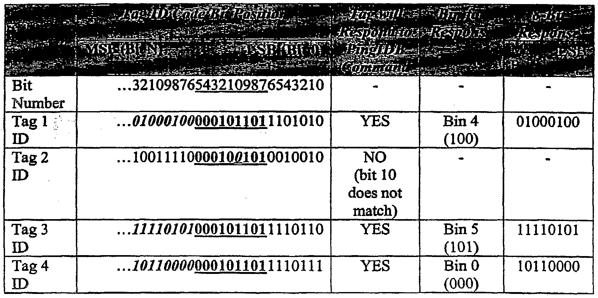
sent from the reader after a setup interval as previously described. The three bits of tag memory directly above the matched data may be used to determine the particular response interval for a tag reply. For example, tags having the next three bits above the matched data of '000' respond in the first interval, tags with the next three bits higher of '001 ' reply in the second interval and so on out to ' 111 ' in the eighth interval. These intervals are referred to as bins numbered zero (0) through seven (7). Figure 10 illustrates an example of a tag responding in Bin 5 (binary 101) because the first three bits of its response (101) correspond to the bin number. It will be appreciated by one skilled in the art that a tag may be configured to respond to a PingID command with greater or fewer than eight bits, and that a greater or fewer number of time bins may be defined by using more or less than 3 bits of the response. The PingID command is used extensively in the anti-collision algorithm described below.
[0047] Tags matching data sent in a Quiet command will respond by either changing state or remaining in their present state, depending on which Quiet command is transmitted by the reader. For example, if a Quiet A command is sent, matching tags in State A will transition to State B while matching tags in State B will remain in State B. Conversely, if a Quiet B command is sent, matching tags in State B will transition to State A while matching tags in State A will remain in State A. [0048] The PingID command in either the A or B version divides a population of tags, in one exemplary embodiment, into eight sub-populations based on their addresses by binning tag responses into eight separate time slices. This binning provides the basis of an anti-collision algorithm that probes the binary address tree three bits at a time. Individual tags can be isolated from large populations in the field of the reader by issuing
multiple PingID commands to the field, analysing the responses and eventually issuing
1 the appropriate ScrollID command to identify individual tags. [0049] Figure 11 illustrates the use of the PingID command to execute a binary tree search on a population of tags. A PingID command with [PTR] = 0, [LEN]=1 and [VALUE] = 0 probes the right half of this tree (the zero branch) through the first four bits of tag memory. Similarly, a PingID command with [PTR] = 0, [LEN]=1 and [VALUE] = 1 probes the left half of this tree (the 1 branch) through the first four bits of Tag memory. [0050] For the PingID command with [PTR] = 0, [LEN]=1 and [VALUE] = 0, tags with least significant bits (LSBs) of 0000 respond in bin 0, Tags with LSBs of 0010 respond in bin 1 and so on, out to bin 7 where tags with LSBs 1110 respond. Readers can look for backscatter modulation from the Tags in each of these bins and learn about the Tag population even if collisions make reading the eight bits of data sent by the tags difficult.
, Merely the presence of backscatter in a given bin is an indication that one or more tags match the query. The bin number tells the reader what the next three most significant bits (MSBs) of tag address are. [0051] As an example, assume a population of tags in State A with multiple tags having addresses with LSBs of 0111 and 1011. A PinglDA command with [PTR]=0, [LEN]=1 and [VALUE]=1 will probe the left half of the tree, shown as Query 1 in figure 12A. The [VALUE] field of 1 matches the first bit of all the tags in this example, making them eligible to respond. During the reply interval, these tags will modulate the next eight bits of their address data above the matched portion. The bin in which they modulate is determined by the three LSBs of the data they will modulate. At the reader, backscatter modulation is observed in bins three (3) and five (5), as shown in figure 12B.
Because multiple tags are modulating in each of these bins, contention is observed, but the reader now knows there are tags present, and that there are two distinct populations with the first four LSBs of 0111 and 1011, respectively. Furthermore, if the tags are programmed to respond with four interval bit cell modulation, as discussed above, the reader may be able to determine in which bits the multiple responses differ and thereby glean additional information about the tag population. Figure 13 illustrates contention detection in the case of two tags responding in bin 3 (LSBs= 011) and differing in their most significant bit. The superposition of the two responses creates an indeterminate response that is neither a logical zero nor a logical one, so the reader knows there are at least two tags present that differ in that bit position.
[0052] Using this information, the reader may issue a second PinglDA command to explore the population of tags in bin three, reserving the tags seen in bin five for later analysis. The population in bin three may be explored by issuing a PinglDA command with [PTR]=0, [LEN]=4 and [VALUE]=7 (binary 0111). The effect of this command is to explore three bits farther into the tree towards the MSB from the 0111 position, shown as Query 2 in figure 12 A. The branches highlighted contain groups of tags that match the second query. These are the same tags that were responding to the first query in bin three. In this new query, tag modulation during the reply interval would show up in bins one (1), six (6) and seven (7) as shown in figure 12C. The reader now knows six bits of address information for these tags as well as at least three bits of information for the tag branch not pursued in the first query. The reader may continue in this vein, and use the PinglDA command to follow a branch through the tag ED space until it explores the entire tag address.
[0053] A preferred method to perform an analysis of a population of tags is to take advantage of the reader's ability to detect contention in the reply intervals. In the case The exemplary "divide by eight" anti-collision feature of the PingID command allows one to very quickly reduce the number of tags replying in each bin. For example, in a 100-tag population with random addresses, fewer than four PingID commands, on the average, are needed to isolate a tag, and in the process, other tags are singulated as well. If only a single tag replies in a given bin the reader can decode the eight (8) bits of information being sent from the tag and issue a ScrollID command to that Tag using the [PTR], [LEN] and [VALUE] data that successfully singulate the tag. [0054] To utilize the two-state symmetry of the communication protocol, readers may start by performing an inventory as described above, using the PinglDA, ScroUIDA, and QuietA commands. After no further tags are responding, the reader may issue high level PinglDA commands again (e.g., commands at the root of the search tree) to explore any tags which were missed in the initial search. Note that a tag in state A would be counted even if it were only powered for a brief time, just long enough to see a command to synchronize its clock, a PinglDA command, a ScroUIDA command, and a QuietA command. At this point all tags that were inventoried in state A would be in state B. The reader can then begin an inventory of tags in state B using the PinglDB, ScrollIDB, and QuietB commands in a process completely analogous to the state A inventory. This second inventory would count all of the tags that were put into state B as a result of the state A inventory, as well as tags that were in state B initially and riot counted in the state A inventory. [0055] Any tag that is continuously in the field is counted in every A/B inventory
cycle. Any tag that enters the field will be counted, in the worst case, in the second inventory after it enters the field. For tags at the edge of the detection range, as multipath interference changes, or as the tag or other objects are moved in the reader field, the power available to the tag fluctuates and may only be sufficient to power the tag for brief periods of time. Persistent quiet allows the majority of tags to be counted quickly and for high-level pings to be generated over arid over again, seeking out tags that are only intermittently powered. The symmetrical commands extend this counting capability to tags that have just been inventoried and put into the quiet state, or as part of a continuous inventory process. One advantage of this approach is that it prevents the tags from ever entering a state where they are hard to count. v
[0056] In one embodiment, tags within a population of tags may be assigned to different sessions to enable a reader, or multiple readers, to conduct inventories in orthogonal search spaces. For example, a tag memory may contain both a state bit and a session bit. The state bit may be set to 0 or 1 , corresponding to states A and B, respectively, and the session bit may be set to 0 or 1, corresponding to session 1 or session 2, respectively.
[0057] One example of the use of two sessions is a portal reader, which is counting all tags coming through a portal, that wants to preferentially count pallets. The reader could run two simultaneous processes on the tag population. Session 1, for example, could be used by one process to sweep the entire population of tags between state A and state B to insure that all tags are counted, regardless of their initial state. Session 2 could selectively mask all pallet tags to state A for that session and all other tags to state B, and then count them preferentially in an interleaved process, without interfering with the
ongoing inventory in the first process.
[0058] Another example of sessions would be a set of store inventory readers, set to synchronize their inventory types. The readers might use session 1 at the tags to inventory from state A to state B and back to state A. At the same time, a handheld reader might use session 2 to search for a specific product code by masking a sufficient portion of the product identification code to state A while masking all other tags to state B. It may then use session 2, state A commands to seek that specific tag or tag type. It will be appreciated that the number of sessions will only be limited by the number of bits in the tag memory that are devoted to session flags.
[0059] In some applications, it may be useful to exclude tags from an inventory that are not of interest, without running multiple sessions. Excluding tags that are not of interest is preferable to selecting tags that are of interest. A tag of interest that is missed by a selection command will be left out of the inventory. On the other hand, a tag that is not of interest, which is missed by an exclusion command, may be inventoried if its ID falls within the parameters of the search. However, once the tag is identified, it can be ignored.
[0060] Tags that are not to be counted may be excluded by using AB symmetry. During each phase of an inventory, A to B or B to A, commands may be issued to transfer tags that are not of interest to the other state without inventorying them. For example, if an inventory is being done from the A state to the B state, a command may be issued to place all tags which are not of interest into state B. These commands can be issued as often as desired during the inventory. The remaining tags are inventoried from state A to state B one at a time. If any tags are missed by the commands to exclude them,
they are simply counted and the information is ignored. When it is determined that no more tags remain in state A, the same procedure may be run from the B state to the A state. Commands may be issued to place all tags that are not of interest into state A without inventorying them. Again, these commands may be issued as often as desired during this part of the inventory cycle. The remaining tags are inventoried from state B to state A, one at a time. If any tags are missed by the commands to exclude them, they are simply identified during the inventory and the information can be ignored. [0061] This method of excluding unwanted tags from the inventory does not allow a complete Boolean expression to be issued that incorporate tag condition primitives as discussed in US patent 5,828,318, incorporated herein by reference. However, the selection methods described therein do not avoid the problem that some tags in the population may miss any particular command. It is desirable, therefore, to combine the specification of complete Boolean expressions over the primitive set conditions available at the tags with the ability of AB symmetry to work in the presence of unreliable communication with the tags. The methods of Boolean selection set out in US Patent 5,828,318 may be combined with the AB symmetric inventory process by using a separate three state methodology as described in U.S. Patent 5,828,318 to set up an unselected population of tags. This unselected population may be set up as often as desired, controlling their participation in the inventory process at a specific interval during the inventory, without affecting the population of the AB states. [0062] In one embodiment of a combination of AB symmetry and Boolean selection, a three state method may be implemented. To avoid confusion, and without loss of generality, the three states of the three state machine described in US patent number
5,828,318 may be named state #1, state #2, and state #3. State #1 may be the unselected state, and tags that are in state #1 do not participate in the inventory. [0063] During the initial phase of an inventory, A to B for example, commands may be issued to put tags that are not of interest into state #1. Both of the other two states of the three state machine described in U.S. Patent No. 5,828,318 would be treated as selected states. These commands may be issued as often as desired during the inventory, to achieve the desired Boolean selection criteria. The remaining tags are inventoried from state A to state B, one at a time. If any tags are missed by the commands to exclude them, they are simply counted and the information is ignored. Once a sufficiently large amount of time has been expended making sure no tags remain in the A state, the same procedure can be run from the B state to the A state. Commands may again be issued, and as often as desired, using the method described in U.S. Patent 5,828,318 to put tags that are not of interest into unselected state #1. The remaining tags are inventoried from state B to state A one at a time. If any tags are missed by the commands to exclude them, they are simply counted and the information is ignored. Thus, all of the tags of interest in the population are counted without having to count most of the tags that are not of interest. No tag is required to receive any particular command to achieve this objective/ This allows a Boolean complete expression, using tag condition primitives, to be used to select the tags of interest out of the population.
[0064] Figure 14 illustrates one embodiment of a method to identify devices using a deterministic search process. Figure 14A illustrates a basic recursive process that may be used to walk down a binary search tree. At step 1401, an initial Ping command may be issued. This initial Ping command may be a high level command that searches at or near
the root of the binary tree, but it may commence the search at any level of the tree. At step 1402, Ping responses may be detected in a plurality of time bins as discussed above. The responses in each bin are evaluated. If a bin has no responses, that bin is ignored, step 1403. If a bin has only one response, that responding tag is identified and put into the other state, step 1404. If a bin has more than one response, that bin is searched by issuing a lower level ping command, step 1405, and the process is repeated until there are no more responses.
[0065] Figure 14B illustrates how the basic recursive search method of figure 14A may be implemented using A/B symmetry to deterministically singulate and count tags •one at a time. To start, a reader issues ahigh level PingA command select one half of the search tree (e.g., as illustrated in figure 10), step 1407. The reader then listens for tag responses in each time bin, step 1408. Any bin with no responses is ignored, steps 1409 and 1410. If any bin has only one response, the tag responding in that bin is identified and placed in state B, steps 1411 and 1412. If a bin has multiple responses, the reader issues a lower level PingA command to separate the responses in that bin, steps 1413 and 1414. The reader then listens for responses to the lower level PingA command, repeating step 1408. The process repeats until there are no more responses at step 1413. If the entire tree has not been searched at step 1415, the search returns to another high level PingA command, step 1407, and the next branch of the tree is explored. If the entire tree has been searched at step 1415, all of the tags in state A have been inventoried and placed in state B. The search then continues with a high level PingB command, step 1416, to initiate a binary search for all tags in state B. The state B search, steps 1416 through 1424, are completely symmetrical with respect to the state A search, steps 1407 through
1415.
[0066] In the foregoing method, every tag in the population is identified when it sends its product identification code to the reader. A product identification code may contain 48, or even 96 or more bits. If the tag also sends a CRC checksum for error checking, the transmission time may be quite long. One approach to reducing the overall time required to conduct an inventory is the use of pseudorandom number pre- acknowledgements. In this approach, a tag that matches the interrogation code will respond with a pseudorandom number, with a high probability of being unique in its response interval, which is much shorter than the full EPC™ code. [0067] . It will be apparent from the foregoing description that aspects of the present •invention may be embodied, at least in part, in software. That is, the techniques may be carried out in a computer system or other data processing system in response to its processor, such as a microprocessor, executing sequences of instructions contained in a memory, such as reader memory 24 or tag memory 46. In various embodiments, hardwired circuitry may be used in combination with software instructions to implement the present invention. Thus, the techniques are not limited to any specific combination of hardware circuitry and software nor to any particular source for the instructions executed by the data processing system. In addition, throughout this description, various functions and operations are described as being performed by or caused by software code to simplify description. However, those skilled in the art will recognize what is meant by such expressions is that the functions result from execution of the code by a processor or controller, such as the microprocessor 23 or the controller 37.
[0068] A machine readable medium can be used to store software and data which when executed by a data processing system causes the system to perform various methods of the present invention. This executable software and data may be stored in various places including for example memory 24 or 46. Portions of this software and or data may be stored in any one of these storage devices.
[0069] Thus, a machine readable medium includes any mechanism that provides (i.e., stores and/or transmits) information in a form accessible by a machine (e.g., a computer, network device, personal digital assistant, manufacturing tool, any device with a set of one or more processors, etc.). For example, a machine readable medium includes recordable/non-recordable media (e.g., read only memory (ROM); random access memory (RAM); magnetic disk storage media; optical storage media; flash memory devices; etc.), as well as electrical, optical, acoustical or other forms of propagated signals (e.g., carrier waves, infrared signals, digital signals, etc.); etc. [0070] In the foregoing specification, the invention has been described with reference to specific exemplary embodiments thereof. It will be evident that various modifications may be made thereto without departing from the broader spirit and scope of the invention as set forth in the claims. The specification and drawings are, accordingly, to be regarded in an illustrative sense rather than a restrictive sense. Further detailed descriptions of certain exemplary embodiments of the present invention that may use aspects of a command structure that has at least a two-state symmetry or aspects of a three-state symmetry, as described herein, can be found in the following sections and in Appendix A.
1 OVERVIEW AND CONTEXT
This document describes a generation π RFID protocol. The goal of this invention is to achieve a fast, robust, compatible and extensible protocol for class 1, class 2, and class 3 RFID tags, while allowing very inexpensive implementations for both tags and readers. The RF transport layer of this protocol focuses on UHF operation. The protocol is expected to be applicable from 400MHz to 2.45 GHz.
1.1 Tag Classes
Four classes of Tags are envisioned to accommodate different applications and cost requirements.
Tags of different classes that meet the requirements of all of the design layers will be able to work together. Tags may also include a standardized wired I/O interface to sensors, clocks, displays and other devices. • Class-I Simple passive, read-only backscatter Tags, designed for lowest cost production. Class I Tags have a one-time programmable memory. o Write once identity memory o 64 or 96 bit ePC Code. o Optional recycling code • Class-II Passive backscatter Tags with higher functionality and cost than Class I in addition to the Class I features: o Can write and read data into and out of tags. o read-write memory o May have battery power for non-communication purposes. o Optionally have sensors and data loggers. Class-Ill Semi-passive backscatter Tag. In addition to class II features: o Built-in battery or other energy source to support increased read range. • Class-IV Modem-like semi-passive or active (transmitter) Tags that can wirelessly communicate with each other and or other devices. This protocol only addresses class IV tags in as much as they will act like readers under this protocol, and will also emulate this protocol's class 1-3 tags to other readers.
1.2 Minimum Features
RFID systems defined by this specification provide the following minimum features: • Identify single Tags in the field of a Reader • Provide anti-collision functionality to manage reading of multiple Tags in the field of a Reader. • Manage errors in the system from sources of RF interference and marginal Tags. • Coexist with systems operating in compliance with local RF regulatory requirements. • Coexist with systems operating in compliance with local RF regulatory requirements.
2 INTRODUCTION
2.1 Scope
The UHF system defined herein will include Readers (interrogators) and Tags (transponders). This document describes a reader talks first system using passive backscatter RF Tags.
The specification does not attempt to provide guidance on specific product definition or detailed aspects of hardware design, except where this is a consequence of defining the behavior across the air interface. Overall system architecture is considered a function of the marketplace. It is the prerogative of manufacturers to design superior or cost effective products embodying this specification.
The intent is to establish on open standard protocol for backscatter tags so that by using these international standards, a system may be defined which is open to all other systems obeying the same standards throughout the world.
2.2 Objectives
Establish an open, flexible, robust RFID VLC Tag specification to enable the development of very low-cost systems that will accelerate the broad adoption of RFID for high volume applications worldwide. In particular, satisfy item identification and tracking needs of the production, distribution, and retail supply chain. Provide flexibility to address future applications and to allow for future design.
Allow and encourage competition, by providing a structure for basic compatibility across systems. Sufficient detail is provided to enable vendors to design and manufacture Readers and/or Tags that will meet this compatibility goal.
2.3 Features of VLC Tags
• Small Integrated Circuit (IC) Area to Permit Low Cost • Small Memory • Precise Timing Not Required • Atomic Transactions (State Storage Not Required)
2.4 VLC Tag Components
A VLC tag is comprised of an antenna and an integrated circuit, connected together. The I.C. implements the command protocol and contains the ePC code. The antenna receives the Reader interrogation signals and reflects the interrogation signal back to the reader in response to a modulation signal created by the LC.
Drawing Omitted
2.5 VLC Tag LC. Block Diagram
The Tag LC implements the VLC Tag by combining an RF interface and power supply, data detector, state logic, data modulator with memory.
Drawing Omitted
The RF Interface and Power Supply converts the RF energy into the DC power required for the VLC LC. to operate, and provides modulation information to the Data Detector and Timing block. The RF interface also provides a means of coupling the Tag Modulation signals to the antenna for transmission to the Reader.
The Data Detector and Timing block de-modulates the Reader signals and generates timing and data signals used by the State Logic.
The State logic provides the command and control functions that coordinate all of the functions of the VLC LC. The state logic interprets data from the Reader, performs the required internal operations and determines if a Tag will respond to the Reader. The State Logic implements the State Diagram and Communications Protocol's described in Section 7.
The Tag Memory block contains the ePC code of the item tagged by a VLC Tag.
The Data Modulator translates the binary Tag Data that into a signal that is then applied to the RF Interface and then transmitted to the Reader.
2.6 Specification Layers
Flexibility and adaptability will be achieved with a "layered" specification, allowing different products to match the specifications of selected layers according to the needs of the target application.
The four layers addressed by this specification include:
Physical and Environmental Characteristics => Defines a limited set of mechanical, environmental, reliability and manufacturing requirements.
RF Transport Layer => Specifies RF coupling between Reader and Tag (may be frequency specific).
Communication Layer => Defines communications / data protocols between Readers and Tags.
Application Layer => Defines protocols and formats for communicating with Readers from Applications.
3 REFERENCED DOCUMENTS
3.1 Normative References • ISO CD 18000-6 UHF RFID Protocols That Support ISO/IEC 18000-1. • ISO/EEC 3309: 1993. "Information technology — Telecommunications and information exchange between systems — High-level data link control (HDLC) procedures ~ Frame structure." • ISO/IEC 7498-1:1994. "Information Technology— pen Systems Interconnection — Basic Reference Model: The Basic Model"; International Standards Organization ISO/IEC JTC1/SC21; 1994. • US Code of Federal Regulations (CFR) Title 47, Chapter I, Part 15. "Radio Frequency Devices"; U.S. Federal Communications Commission, 1999.
3.2 Informative References
• MIT Auto-JD Center Publications: htto.7/www.autoidcenter.oηz/ • 860MHz-930MHz Class I Radio Frequency Identification Tag Radio Frequency & Logical Communication Interface Specification Candidate Recommendation, Version 1.0.1, MU-AUTOID-WH-007 • The Physical Markup Language - A Universal Language for Physical Objects, D.L. Brock, MIT-AUTOID-WH-003, Feb 2001. • The Electronic Product Code - A Naming Scheme for Physical Objects, D. L. Brock, MIT-AUTOID-WH-002, Jan 2001. • The Compact Electronic Product Code A 64-bit Representation of the Electronic Product Code, D. L. Brock, MIT AUTO-ID- WH-008, Nov.2001. • The Networked Physical World - Proposals for engineering the next generation of computing, commerce, and automatic-identification, MIT-AUTOID-WH-001, Dec 2000. • IEEE 802.11. "Standard for Wireless LAN: Medium Access Control (MAC) and Physical Layer (PHY) Specification"; Institute of Electrical and Electronics Engineers; 1997. • ETSI EN 300220-1 Vl.3.1 (2000-09) "ElectroMagnetic Compatibility and Radio Spectrum Matters (ERM); Short Range Devices (SRD); Radio equipment to be used in the 25 MHz to 1 000 MHz frequency range with power levels ranging up to 500 mW; Part 1 : Technical characteristics and test methods"; European Telecommunications Standards Institute (ETSI) Reference: REN/ERM-RP08- 0403-1. • ETSI EN 300 761-1 Vl.2.1 (2001-06) "ElectroMagnetic Compatibility and Radio Spectrum Matters (ERM); Short Range Devices (SRD); Automatic Vehicle
Identification (AVI) for railways operating in the 2,45 GHz frequency range; Part 1 : Technical characteristics and methods of measurement" European Telecommunications Standards Institute (ETSI). Reference: REN/ERM-RP08- 0411-1.
RCR STD-33A. "Radio Equipment for Low Power Data Communications System Radio Station"; Japan Research and Development Center for Radio Systems; 1 Mar 1993.
NTIA Red Book Chapter 7 Annex K. "The NTIA Manual of Regulations & Procedures for Federal Radio Frequency Management"; National Telecommunications and Information Administration; Edition 9/95, with Revisions for September 1996, January and May 1997.
NTIA Orange Book, "The NTIA Manual of Regulations & Procedures for Federal Radio Frequency Management"; National Telecommunications and Information Administration.
JEDEC Standard JESD22-A114-B, "Electrostatic Discharge (ESD)Sensitivity Testing Human Body Model (HBM)", June 2000.
4 RFID TERIVIINOLOGY
4.1 Abbreviations
AM Amplitude Modulation
API Application Programming Interface
ASK Amplitude Shift Keying bps Bits per second
CCAG Cheap Chip Action Group
CRC Cyclic Redundancy Check
CW Continuous Wave
DLL Data Link Layer (OSI Model)
EME Electromagnetic Exposure ePC Electronic Product Code
ESD Electrostatic Discharge
FCC Federal Communications Commission
FM Frequency Modulation
FSK Frequency Shift Keying kbps kilobits per second kHz kilohertz (103 Hertz)
FM Frequency Modulation
HBM Human Body Model
LSB Least Significant Bit ms milliseconds (10~3 seconds)
MHz megahertz (106 Hertz)
MSB Most Significant Bit ns nanoseconds (10"9 seconds) ppm Parts per million (10*6)
PM Phase Modulation
PSK Phase Shift Keying
RAM Random Access Memory
RF Radio Frequency
RFID Radio Frequency Identification
RTF Reader Talks First us microseconds (10"6 seconds)
VLC Very Low Cost
V/m Volts per Meter
4.2 Numeric Conventions
In this document, references to bits in the memory of RFID Tags are made extensively. To avoid confusion, the following terms are introduced here:
When referring to bits in Tag memory, the words "up" or "higher" will refer to the Most Significant Bit (MSB) direction and the words "down" or "lower" will refer to the Least Significant Bit (LSB) direction.
Example: The binary representation of the decimal number seven (7) is 0111. Shifting each bit "up" or "higher" by one yields the decimal number fourteen (14), represented in binary as, 1110.
5 PHYSICAL/ENVIRONMENTAL CHARACTERISTICS
5.1 VLC Tags
5.1.1 Antenna
The intent of this specification is to define functional capabilities without specifying Tag antenna construction or how Tags are to be applied to various items. Tag size and performance will vary based upon the material being tagged and operating frequency. It is expected that Tag antenna design and application variations will be selected by vendors to yield optimum performance.
5.1.2 Range
It is recognised that tags will have a range of performance, with some applications only requiring a short range. For that reason, a tag is allowed to meet this standard without any particular minimum range. For reliable system performance in cases where many object tagged by different manufacturer's tags are being inventoried, however, tags will need to meet certain minimum range specifications. This is specified by means of range group. A ePC class 1 range group A tag is, as a minimum, readable at 95% of orientations at a range of 2 meters in an anechoic chamber beam when attached to the intended object. The test conditions are: 1 watt emission by the reader, 6 db gain antenna, circular polarization, and a backscatter signal of -65dbm at the reader antenna terminals. Tags in range group B are required to be readable under the same conditions at 4 meters, but with a backscatter of at least -70dbm at the reader antenna terminals.
5.1.3 Temperature • Minimum operating temperature range: -25°C to +65°C • Minimum storage temperature range: -50°C to +85βC
5.1.4 Photosensitivity • Tags should function while exposed to direct sunlight. • No loss of stored data shall occur following direct exposure to sunlight for a period of 200 hours and at a temperature not exceeding +70 C.
5.1.5 ESD • Tag ESD withstanding capability >1.5 kV HBM according to JEDEC Standard JESD22-A114-B.
5.1.6 RF Stress • RF stress - Tag shall be operable following transient exposure to 400 V/meter for
1 ms and continuous exposure to 50 V/m.
5.2 VLC Readers
Due to the many varied applications and environments, physical attributes of Readers are not defined in this specification. Readers are defined by functional characteristics only. However, the following is assumed. • This specification should impose only minimal constraints on the way shelves are stocked. • To support wide application, Readers will be designed for operation at unlicensed power levels under the local regulatory environment. • The Reader size and shape will be defined by antenna design and available space in the target environment • Reader antennas may have different polarizations (linear, circular, elliptical) to yield the best performance for an application. • The bandwidth of the reader should be appropriate for the particular UHF band of operation. • Unit-to-unit variation in performance, specifically sensitivity variation, should be within 3 dB for identical Reader models when measured in an open environment. This is to permit interchangeability of Readers and simplify the task of setup and maintenance.
6 RF TRANSPORT LAYER
The RF Transport Layer defined herein specifies parameters for UHF operation. Performance criteria have been designed to work, as far as possible, at different parts of the frequency spectrum. Performance variation is anticipated under different regulatory environments.
6.1 RF Power Management
Reader RF Power Management will be consistent with local regulations to allow for unlicensed operation. For operation in North America, readers will maintain RF emissions consistent with FCC part 15.247 limits and Electromagnetic Exposure (EME) limits. RF Power levels and antenna designs for Readers in the US shall be consistent with these regulations. In Europe, modulation characteristics will be adjusted to allow for unlicensed operation in that regulatory environment.
6.2 Half-Duplex Operation
The Tag-to-Reader and Reader-to-Tag link is defined as half-duplex. Readers initiate communication with Tags by sending a command sequence. The reader then provides a reply period for the tag by transmitting an un-modulated carrier while listening for a reply from the Tag. The tags are not expected to be able to detect reader modulation while they are replying.
6.3 Frequency
The RF transport layer of this specification is applicable to the following bands: North American 902-928 MHz and 2400.0-2483.5 MHz, existing European 869.4-869.65 MHz, proposed 865.6-867.6 MHz European, and UHF bands near 2450 MHz. Each specific frequency band and country may have differences in bandwidth, power, modulation and regulatory certification. It is hoped that as additional RF Transport Layer Specifications are developed, the other layers (i.e. Communication Layer, Application Layer, and Physical and Environmental Characteristics) will be minimally impacted.
The UHF bands called out above were chosen for the first VLC Tag products for the following reasons: • High speed (up to 70.175 Kbps in North America) Reader-to-Tag system data rate. • 140.35 kbps or faster Tag-to-Reader system data rate. • Consistent operation with high "hit rates" at ranges of 2 meters or more under typical conditions, 5 meters or more in an anechoic chamber.
• Relatively small Tag and Reader antennas. • Human exposure to low-level UHF is already common and accepted worldwide (i.e. cellular telephones). • North American bands are wide enough to permit significant frequency hopping.
Performance, read range, and speed of operation are expected to vary depending on the regulatory environment under which the system is deployed.
6.4 Reader-to-Tag Modulation
Readers are in one of three available states; OFF, (emitting no RF energy), CW (emitting RF energy at some power level without amplitude modulation), and Active (emitting RF energy with amplitude modulation).
In the Active state, the Reader-to-Tag link makes use of Amplitude Shift Keying (ASK) with a minimum modulation depth of 20%. Modulation shape, depth and rate of modulation are variable within the limits described below. Compliant Tags will adjust their timing over a range of modulation rates to lock to reader transmissions automatically.
Reader to Tag Modulation
- Drawing Omitted -
The modulation parameters in general are illustrated in Figure A.4, and in Table TJ, North American Modulation Pulse Parameters and Table T.2, European Modulation Pulse Parameters. Specific values are a function of the local regulatory environment
- Drawing Omitted
Definitions:
To Elemental Clock Cycle period. Time for a single bit sent from Reader to Tag.
Tr Rise time of modulation envelope, 10% to 90% of Modulation amplitude variation.
Tf Fall time of modulation envelope, 90% to 10% of Modulation amplitude variation
Tfwhm Pulse width of modulation envelope measured at 50% of Modulation amplitude variation.
Mod Amplitude variation of modulated carrier.
Ripple Peak to Peak variation in modulation overshoot and undershoot at edges of intended modulation.
Dmod Peak to Peak variation in modulation depth from intended value.
Toτoi Master Clock Interval Tolerance, Basic accuracy of reader signaling.
Tew Minimum CW time immediately before a command.
Tcoast Maximum Time duration between EOF and the next command, to ensure that the tag clock is sufficiently accurate to decode the next command
For all Reader modulation sequences, it is anticipated that the Reader clock must be stable to within 1% over the length of a transaction.
All other "Elemental Clock Cycle" timings are proportional to the modulation clock frequency To.
6.4.1 North American Parameters
In North America, data rates at or above 70.175 kbps should be achievable under FCC part 15.247 regulations with the modulation parameters shown in the Table T.1. All times and frequencies scale with To, except as noted.
Table T.l, North American Modulation Pulse Parameters
6.4.2 European Parameters
In Europe, bandwidth issues under ETSI EN 300-220 force a slower Reader-to-Tag modulation rate to meet spectral requirements. The parameters in Table T.2 are recommendations based upon current European regulations, and are subject to change as regulatory requirements evolve in the region. Tags are required to respond correctly to readers with clocks intermediate between the North American and European rates, as long as the features have the given ratios.
Table T.2, European Modulation Pulse Parameters
6.4.3 Reader-to-Tag Modulation Encoding
Readers communicate with the Tag field using two types of modulation: Data Modulation and Bin Modulation. Data Modulation is used to transmit data from the Reader to the Tags. Bin Modulation is used during the Tag reply interval during the anti- collision algorithm to specify time slots for Tag responses.
- Drawing Omitted -
All transactions begin with a minimum CW period preceding each command to allow the tag to locate the beginning of the command
During the Data Modulation of a command, Active Readers provide a master clock signal to Tags in their neighborhood. The time between clock ticks, To, determines the Reader- to-Tag data rate.
The Tags are synchronized to the Active Reader on the negative-going edge of the low interval of the RF envelope. All subsequent signaling is tied to this fundamental frequency in a proportional manner.
Binary data from Reader to Tag is encoded as pulse width modulation of the low level pulse. Logical zeros are defined as a modulation whose width is one fourth (1/4) of the master clock interval, To. Logical ones are encoded as a modulation whose width is one half (1/2) of the master clock interval, To.
Drawing Omitted
During Bin Modulation eight (8) pulses are sent by the Reader to delineate between nine (9) time intervals. The first interval, after the EOF, is used for Tags to set up for modulation. The remaining eight are used to delineate response intervals for the Tags.
The width of the delineation pulse, Tf w mB-n, is (l/2)To or the equivalent of a logical one. The width of the intervals in F2F mode, TftvhnβmRWRF. is eight (8) times To. The width of the intervals in FMO mode, TfwhπiBinRWFMO. is four (4) times To.
After the last pulse, the Tag must be ready to receive the next command after the minimum CW time, and be able to decode a command received within a Tcαut interval. Refer to Figure A.7, Bin Modulation for illustration.
Drawing Omitted
A single Bin Response Window is illustrated in Figure A.8.
Drawing Omitted -
6.4.4 Coast Interval
In order for the Tag to be able successfully decode the next command, the reader must start the next transaction within the Tcoast interval. This restriction does not apply when
the carrier has been turned off for sufficient time for the tag to loose DC power, as the tag will re-synchronize at the next power up.
EOF Coast Tag Reply Intervals v Λ'Villiϊiiill.ilillllij I -t llllili U--- PinolDU---
Figure AJ>, Coast Interval
6.4.5 Data Modulation Timing
Modulation of the pulse width (RF interruption period) is used for data transmission to Tags. Two symbols are defined by the low time and scale with To. T atao is used to encode binary "0" data. T^i is used to encode binary "1" data. One symbol is transmitted per each To interval* Refer to Table T.2, European Modulation Pulse Parameters, for nominal time values for USA and European operation.
Reader Logic 0 TdataO- 1/4 of To
Reader Logic 1 Tdatai => 1/2 ©f Tø Table TJ, Reader Data Modulation Timing
6.4.5.1 Data Modulation Timing Data "0"
Data Modulation Timing, Tdatao, for Reader-to-Tag clocking when data = "0" is encoded by a "narrow" 1/4*T0 pulse width modulation.
Figure A.10, Data Modulation Timing - 0
6.4.5.2 Data Modulation Timing Data "V rtt
Data Modulation Timing, Tdatai, for Reader-to-Tag clocking when data = "1" is encoded
by a "wide" 1/2 * T0 pulse width modulation. This timing is also used for Bin Pulse features.
Figure A.ll, Data Modulation Timing- 1
6.4.6 Bin Modulation Timing Modulation of negative pulse width (RF interruption period) used for designating response bins for Tags after a PINGID command is issued. Refer to Table T.2, European Modulation Pulse Parameters, for nominal time values for USA and European operation.
Table T.4, Reader Bin Modulation Timing
47
SUBSTITUTE' SHEET (RULE 26)
Bin Modulation Timing for a Reader with a 70.175 KHz master clock interval is illustrated in Figure A.12.
Drawing Omitted
6.4.7 PingID Reply Bin Collapse
The Reader may optionally shorten the time for a PingID transaction by shortening the Bin Response Window. The Reader may listen for a Tag reply during the Bin Response Window, and if a reply has NOT been started by a Tag, prior to expiration of 14 of Bin Response Window, shorten the duration between the Bin Modulation pulses for that bin down to 2 * To. This may be applied for each of the eight bins in which the Reader detects no reply from a tag. The middle bin in Figure A.13 has been shortened due to no Tag reply. The end of bin 7 is delineated by the start of the next command, and may not be reduced in length shorter than the minimum Tew interval required for the next command. This is intended to allow the tag to use a hardware device, independent of the clock, to determine when to open a PLL window to sync its clock at the start of a command packet.
A bin should not be collapsed if a Tag is responding in that bin. If the reader collapses an occupied bin, the reply of the occupying Tag may overlap the collapsed bin and continue into the next bin. The Reader may see the reply as a collision in the next bin, and will need to resolve with subsequent search commands.
- Drawing Omitted -
6.5 Tag-to-Reader Modulation
The Tag-to-Reader modulation is selected by the [MODULATION] bit, and is either FMO in the case of [MODULATION]=0, or F2F, in the case of [MODULATION]^ All tags are required to implement both FMO and F2F encoding. The primitive for each modulation method is the same, with the same timing, but two FMO primitives are used to encode each bit of F2F.
Comment: the F2F encoder can be implemented by using a FMO encoder preceded by a bit inverter and encoding twice for each bit in succession.
FMO:
Tags reply to Reader commands with backscatter modulation. There is a change of backscatter state between each bit period, and a 0 bit has an additional change of backscatter state at the center of the bit time. The nominal data rate for Tag to Reader is four times the Reader to Tag Rate, but may vary up to ±10% over an 80 bit response window due to oscillator drift in the Tag. It is anticipated that FMO will be used in cases where the backscatter noise environment can be controlled, i.e. shielding around fluorescent lamps, etc.
F2F:
Tags reply to Reader commands with backscatter modulation that follows a four (4)- interval bit cell encoding scheme. Two (2) transitions are observed for a zero (0) and four (4) transitions are observed for a one (1) during a Bit Cell. The nominal data rate for Tag to Reader is twice the Reader to Tag Rate, but may vary up to ±10% over an 80 bit response window due to oscillator drift in the Tag.
Definitions: To Elemental Clock Cycle period. Time for a single bit sent from Reader to Tag.
Ttagbitcell Tag to Reader bit cell interval.
Tag Data Rate Tag to Reader Nominal Data Rate of for the modulated backscatter.
ItagscrollDe. Reply delay from Reader EOF to start of Tag ScrollID Reply
1 tagpingDel Reply delay from Reader EOF to start of Tag PingID Reply 1 tagreplyNom Tag to Reader reply duration for 88 bit ScrollID reply
ΔTtagbitcdl Tag to Reader bit cell interval variation measured at the last bit of a ScrollID reply.
To toast Maximum Time duration between EOF and the next command.
6.5.1 North American Parameters
Table T.S, North American Tag to Reader Modulation Parameters,
6.5.2 European Parameters
Table T.6, European Tag to Reader Modulation Parameters
6.5.3 ScrollID Reply Delay
The delay from the end of data to the start of a reply to a ScrollID or NerifylD Command, TtagscroiiDei, is illustrated in Figure A.14.
Drawing Omitted
6.5.4 PingID Reply Delay
The delay from a Bin Pulse to the start of a reply to a PingID Command, TugpmgDei, is illustrated in Figure A.15.
Drawing Omitted
6.5.5 ScrollID Reply Duration
The duration of a ScrollID Reply, Tta reptyNom is illustrated in Figure A.16.
- Drawing Omitted -
6.5.6 Tag to Reader Bit Cell Variation
The variation in the bit cell duration ΔTugbhceD is illustrated in Figure A.17.
- Drawing Omitted -
6.5.7 Tag to Reader Bit Cell
FMO:
The state of tag backscatter is changed at the edge of each bit, and an additional change of state occurs in the middle of bit intervals which correspond to a "0" data bit A final bit interval transition is inserted at the end if it is needed to leave the modulation in the high state (not in the crowbar state).
- Drawing Omitted
F2F:
The Tag backscatter is modulated by a selection of one of two symbols per bit cell. The bit cell Ttag itceii is defined as:
- Drawing Omitted
Under this encoding scheme there are always transitions in the middle of a bit and unlike Manchester encoding, the sense of zeros and ones are maintained when the code is
inverted. The following figures illustrate this inversion.
Drawings Omitted
6.6 Contention Detection
Contention detection is important for most anti-collision algorithms. When two Tags have the same clock rate and differ by only one bit, the backscatter modulation waveform yields a difference that should be readily detected by the Reader. Shown below are two cases where Tags of equal backscatter modulation intensity are communicating simultaneously. Differences in backscatter modulation intensity can also be used to aid in detection of contention.
6.6.1 Case I
- Drawing Omitted -
6.6.2 Case II
If the two Tags do not have the same clock rates detection of multi-Tag contsntfoii becomes even easier. The figure below illustrates the difference in signal between two Tags that differ by one bit in the modulation with a speed difference of 50%
Drawing Omitted
7 COMMUNICATION LAYER
7.1 Overview
System communication follows a two-stage command-reply pattern where the Reader initiates the transaction (Reader Talks First, RTF). In the first phase, the Reader provides power to one or more passive Tags with continuous wave (CW) RF energy. Tags power up ready to process commands after one command which is used for synchronization of its clocks. The Reader transmits information to the field by amplitude modulation using the Reader-to-Tag encoding scheme described above. On completion of the transmission, the Reader ceases modulation and maintains RF to power the Tags during the reply phase. Tags communicate with the Reader via backscatter modulation during this period using the four (4)-phase bit encoding scheme described above.
Basic Commands are designed to limit the amount of state information the Tags- have to store between transactions. The power available to a passive Tag is a complicated function of transmitted power, Tag/Reader antenna orientations, local environment and external sources of interference. Tags on the margin of the RF field are powered unreliably and therefore cannot be counted on to maintain a memory of previous transactions with the Reader. In particular, moving tags or objects may cause the tag to have power only for brief intervals, primarily due to multipath interference. This protocol is designed to allow the efficient counting of tags under these conditions by minimizing the total transaction time, and by allowing rapid recovery from missed . commands. Tags which have power for as little as 3 milliseconds can be inventoried. There is only one bit of state between sorting commands, and the impact of that state is further lessened by symmetrizing the command set about those two states, as described below.
7.1.1 VLC Tag States
The Tag IC state logic block implements the VLC tag logic by reacting to commands received from a Reader or Programmer according to the following general state diagram. These State diagrams are included to convey the concept, and general function of the Tag LC and actual implementation may be manufacturer and technology dependent.
Drawing Omitted -
7.1.1.1 VLC Tag State Diagram
The tag state diagram shows all the states that a tag may take between command groups1. The DEAD state is a permanent state. States A and B are intended to be persistent states, even in the absence of power. After a long period of time, at least 20 seconds but possibly hours, state B will revert to state A. In state A, all tags respond to PinglDA and ScroUIDA commands but not PinglDB and ScrollIDB commands. In state B, PinglDB and ScrollIDB commands are responded tø, but not PinglDA or ScroUIDA commands. If the persistent state memory has expired, the tag will enter into state A upon power up, or optionally enter into a state where it will execute all ping and scroll commands (see section 7.1.2 for alternate tri-state embodiment).
The tag will also maintain a volatile memory of whether it was addressed by the last ping command, and if so, a memory of which ping bin it was in. An invalid command will reset this memory.
7.1.1.2 Power
Upon power up, the tag will look for a long CW interval followed by a short RF on interval. This pattern is guaranteed to only occur at the beginning of a command, and the command will provide a minimum of 15 bits. The tag will sync its clock to the falling edges provided by that command, but is not required to act upon the first command after
1 A command group is a set of sequential commands which use only the relative addressing modes, after the fist command in the group. The volatile memory used for the relative addressing modes expires on loss of power, loss of sync, command error, and upon the use of any other addressing mode .
power up. It will then enter into state A or B depending on the state of its persistent state memory. Power on reset will clear the "addressed by last ping" memory. It will maintain its clock with sufficient accuracy to decode the next command. The tag will also clear the relative addressing mode memory, including the MARKED state and the previous ping memory. 7.1.1.3 State A
While a tag is in state A, it will respond to all commands except PinglDB and ScrollIDB, A tag will enter into state A upon receipt of a valid QuietB command.
7.1.1.4 State B
While a tag is in state B, it will respond to all commands except PinglDA and ScroUIDA. A tag will enter into state B upon receipt of a valid QuietA command A tag will remain in state B for a minimum of 20 seconds, even with loss of power. If the persistent state memory for state B is lost, the tag will power up in state A, or optionally a state where it will respond to all ping and scroll commands.
7.1.1.5 DEAD
The Dead State is a permanent state entered on receipt of a valid Kill Command and Destruct Code sequence, hi the Dead State, the tag will not ever backscatter to a Reader again.
7.1.2 Alternate Tri-State Configuration
In an alternative embodiment of the present invention, a tag may assume three different states. Upon power up it will enter into State A or B or C depending on the state of its persistent state memory.
7.1.2.1 State A
When a tag is in state A, the ground state, it will respond to any command, including PinglDA, PinglDB, PinglDC, ScroUIDA, ScrollIDB and ScrolllDC. Upon receipt of a valid QuietC command, a tag in state A will transition to state B. Upon receipt of a valid QuietB command, a tag in state A will transition to state C.
7.1.2.2 State B
When a tag is in state B, it will respond to A and B commands, including PinglDA, PinglDB, ScroUIDA and ScrollIDB. Upon receipt of a valid TalkB command, a tag in state B will transition to ground state A. Upon receipt of a valid QuietB command, a tag in state B will transition to state C.
7.1.2.3 State C
When a tag is in state C, it will respond to B and C commands, including PinglDB, PinglDC, ScrollIDB and ScrolllDC. Upon receipt of a valid TalkC command, a tag in state C will transition to ground state A. Upon receipt of a valid QuietC command, a tag in state C will transition to state B.
7.2 General Command Format
The General Command Format is designed around the notion that to support very low cost (VLC) Tags, the Reader will have to perform extra work, allowing the Tags to be as simple and inexpensive as possible. This work falls largely into two areas, dealing with timing uncertainty and dealing with limited "long term" memory in the Tags. It is anticipated that Class III and higher Tags (battery powered devices with large memories) will support the Basic Command Format for backward compatibility reasons. Class III and higher Tags may also have a more sophisticated command format to be outlined in later documents that takes advantage of their enhanced capabilities.
VLC, single-chip Tags are expected to have limited oscillator stability, as quartz crystals are cost and size prohibitive. The Tags use the bit timing of commands to synchronize their internal clock, and may need to be powered up and see one full command packet before they can start decoding further commands. Replies from the Tags are structured such that the Reader can interpret the information transmitted by the Tags at whatever clock rate the Tag is able to provide. This scheme is similar in concept to auto- synchronization schemes used in magnetic card or barcode Readers.
Three classes of commands are provided: • Basic Commands, to provide object identification, sorting, inventory, etc. • programming commands that support Tag data initialization and programming by the Tag manufacturers prior to tagged items entering the supply chain • Data link commands which provide a data link layer for class 2 and higher tags.
7.3 Reader Command Structure - (Reader to Tag Communication)
The format of a Basic Command from the Reader to the Tag is composed of seven (7) fields.
7.3.1 Basic Command Structure
[PREAMBL][ADDRMODE][CMD3[PTR][LEN][MODULAΗON][VALUE]
Table T.7, Command structure
7.3,2 Transmission Order
The Reader transmits the PREAMBL field first, and the [VALUE] field is transmitted last. Within each field, the Isb is transmitted first.
Address mode 2 uses 8 bit fields, address mode 3 uses 16 bit fields, and address modes 8- 15 specify relative addressing, referring to the last ping command, as specified below. Address modes 0 and 1 set [PTR] to zero (pointing at ROOT).
Table T.S, Address mode definitions
7.4 Addressing All commands are addressed using same mechanism, as described in the addressing mode table. For addressing modes which return a value for [PTR] [LEN] and [VALUE], the tag will attempt to match the data in [VALUE] to its stored memory, starting at a distance [PTR] from ROOT, for [LEN] number of bits. The map into the identifier address space is determined by the ScrollID prefix and the capability code of the tag, but is required to start at root with a high entropy field which extends for at least 16 bits, preferably 24 or
more bits. Typically ROOT will point at a fixed random number field (if one exists) followed by the CRC, the ePC, and the RECYCLECODE (if one exists). Higher addresses may contain addressable/physically searchable class 2 data, out of range temperature or sensor indicators, etc., depending on the capability code of the tag. Class 1 tags do not respond to commands using mode 3, the 16 bit addressing mode.
7.5 Command Encoding Commands are encoded into two groups; Basic Commands and Prograrnming Commands. Operation of each command is described in Sections 7.5.4 and 7.5.5, respectively. 7.5.1 Basic Command Encoding
Table T.9, Basic Command Coding 7.5.2 Programming Command Encoding The Basic Commands are extended by inclusion of the programming commands:
Table T.10, Programming Command Coding
7.5.3 Class 2 Command Encoding The Class 2 and above tags are extended by inclusion of the following commands:
Table T.ll, type 2 and 3 Command Coding 7.5.4 Basic Commands - Overview There are the eight Basic Commands, described briefly here and in more detail below:
7.5.4.1 ScroUIDA and ScrollIDB Tags matching data sent by the Reader reply by sending back the SCROLLIDPREFTX from the table below, followed by the identification data in the tag starting at root. The only difference between ScroUIDA and ScrollIDB is that tags in state A will not respond to ScrollIDB, and tags in state B will not respond to ScroUIDA. Data sent by the Reader to the Tag may be of variable length. ScrollID can be used to look for specific tags or test for the presence of specific groups of tags in the field.
Table T.12, ScrollID Prolog (8 bit, fixed code in mask set)
7.5.4.2 SCROLLMFG Tags matching data sent by the Reader reply by sending back an eight (8)-bit preamble, and the following data, which is never allowed to be programmable.
Table T.13 SCROLLMFG reply
7.5.4.3 PinglDA and PinglDB These commands are used as part of a multi-Tag anti-collision algorithm described in detail below. The only difference between PinglDA and PinglDB is that tags in state A will' not respond to PinglDB, and tags in state B will not respond to PinglDA. Tags matching data sent by the Reader respond with eight (8) bits of the Tag address, starting at a point designated, somewhat indirectly, by two parameters supplied by the Reader, and proceeding from there toward the MSB of the entire Tag address. Each Tag response is placed in one of eight (8) time bins delineated by clock ticks sent from the Reader. The three (3) least significant bits of the eight bits transmitted by the Tag determine the bin used. 7.5.4.4 QuietA and QuietB The QuietA and QuietB commands are used to place tags into states where they will not interact further with an ongoing inventory, without impairing the ability to get them to respond to a subsequent inventory. QuietA puts the addressed tag or tags into state B, and Quiet B puts the addressed tag(s) into state A. The quieted tag will respond with the ScrollID preamble, enabling applications which maintain an inventory by simply quieting all tags previously known to be in the field, and using the presence or absence of a reply to update their inventory before executing a tree walking search. 7.5.4.5 SETMARKER The SETMARKER command is an addressing command. The MARKED state is held in volatile memory and is cleared at power on reset, and also cleared by the use of any addressing mode other than the addressing mode MARKED. The SETMARKER command itself is addressed the same as other commands. Programming and class 2+ commands are divided into addressing (SETMARKER) and data exchange parts with a
one bit volatile state to allow the tag communications hardware and registers used for addressing to be reused for reading and writing.
7.5.4.6 KILL
The Kill command can only be addressed by the MARKED address mode. Tags matching the kill code sent by the reader in the [VALUE] field are deactivated and will no longer respond to reader queries. This "destruct" command renders the Tag inactive forever. It is anticipated that the Kill command will require higher field strengths from the Reader, and therefore be a short-range operation. The Reader must transmit "l"s for 100 milliseconds, then 100 milliseconds of "0"s, followed by 15 "l"s and then another 100 milliseconds of "0"s after the kill code for the tag to complete the command. The KILL command is required to erase the CRC and ePC, and then permanently deactivate the tag.
7.5.4.7 WIPE
The WIPE command can only be addressed by the MARKED address mode. If a tag does not have a recycling field, the WIPE command will execute the same function as KILL. If it does have a recycling field, tags matching the kill code sent by the reader in the [VALUE] field will erase the CRC and ePC fields of the tag, but will not erase the recycling field. It is anticipated that the WTPE command will require higher field strengths from the Reader, and therefore be a short-range operation. The Reader must transmit "l"s for 100 milliseconds, then 100 milliseconds of "0"s, followed by 15 Ml"s and then another 100 milliseconds of "0"s after the kill code for the tag to complete the command. The WIPE command is required to erase the CRC and ePC, and leaves the tag functional but not programmable. It is anticipated but not required that tags which implement the recycling feature will have a [RAND] hardware random number.
7.5.5 Programming Commands - Overview
Programming Commands use the same command structure and field definitions as the Basic Commands, but are issued only by a Tag programming device, or Programmer. A Tag Programmer may be similar to a Reader, with the exception that it can execute Programming Commands in addition to Basic Commands, in accordance with methods approved by Tag (and IC) manufacturers.
Programming Commands enable programming of the contents of the Tag memory, and verification of the contents of the Tag memory prior to locking the contents
All Programming Commands are disabled once the Tag manufacturer has locked the Tag data contents. The specific timings for programming a Tag are memory technology dependent.
7.5.5.1 VerifylD
The VerifylD command is used to examine the contents of memory as part of a programming cycle in order to allow a manufacturer's Tag programmer to verify that all memory has been programmed correctly into the Tag. The VerifylD command will not execute on Tags that have been LOCKED.
The VerifylD command will address all bits of Tag memory, and the Tag will transmit the entire contents of the ID memory, including the kill code, to the programmer in a manner similar to the ScrollID Reply (refer to Section 7.6). The number of bits transmitted and the interpretation of the reply is dependent upon Tag Class, Type specific lock function implementation.
7.5.5.2 EraselD
The EraselD command sets all bits of the Tag to the value "0". This command is a bulk erase of the entire memory array. The EraselD operation is required prior to the ProgramID command. The EraselD command may not be executed on Tags that have been LOCKED.
The EraselD command is only addressed by the MARKED addressing mode.
The Programmer must send "0"'s after the [EOF] for the duration of the erase time, Tease. The EraselD operation is terminated on receipt of a "1" from the Programmer. The Tag will complete an orderly shutdown of the programining of the Tag within 8 * To intervals, and await the next transaction from the reader.
Upon receipt of a valid EraselD Command the Tag will execute the appropriate internal timing sequences required to erase memory.
7.5.5.3 ProgramID
The Tag programming is accomplished 16 bits at a time. Programming is only allowed if the Tag has not been previously locked.
The tag may be addressed only by the MARKED addressing mode.
The data is sent to the Tag using the ProgramID Command, where the [PTR] filed is the memory row address to be programmed and the [VAL] field contains the 16 bits of data to be programmed into the selected memory row address.
The [PTR] field must be set to the indicated decimal/binary value to indicate to the Tag the row to be programmed:
Table T.14, Programming Row Selection, Class 1 Tag
The [LEN] field must be 16 decimal, binary 00010000, indicating that 16 bits are to be programmed.
Upon receipt of a valid ProgramID Command the Tag will execute the appropriate internal timing sequences required to program memory.
7.5.5.4 LocklD
The LocklD command is required to be issued to lock the identification (CRC and ePC) portions of a tag's memory before it leaves a controlled supply channel. The PTR field should be set to all 1 's. The use of the MARKED addressing mode is required.
7.5.5.5 EraselD, ProgramID and LocklD Timing
The time duration required to erase, lock or program a Tag is manufacturer and technology dependent. The Tag manufacturer may enable others to initialize and program Tags, and will provide the value of Tense Tjock Tprogram-
7.5.5.6 EraselD and ProgramID Reader Signaling
The reader to Tag signaling is the similar to the basic command signaling. The Programmer must send "0*"s after the [EOF] for the duration of the program or erase time, Tpgmor erase.
Figure A.25 shows a graphical representation of the signaling.
- Drawing Omitted -
7.5.6 Class 2 and higher commands - Overview
Class 2 and higher tags use the same singulation method and identification method as the class 1 tags. In addition, they may have additional read/write memory, security features, sensors, etc. Class two tags may also have a battery to realize sensor logging, for example. . '
Class three and above tags are defined to have battery assisted communications. Class three and above tags will respond to class 1 commands in a low power passive mode, or at longer ranges they use a key transmission to go to the battery assist communications mode. The wakeup key for class three and above tags is described in a separate section. This allow them to avoid using their battery assist except for long range exchanges which are specifically directed at them, reducing the use of battery power. It is anticipated that F2F communications will be required for communication at long range.
Communications with class 2 and above tags are standardized into a handle based I/O data link. Handles are issued by "authorizing agency" for a specific purpose, and together with the SCROLLMFG information, can be used to deduce and exercise the capabilities of a tag. A few example capability codes and corresponding handles:
Table T.15, Example (only) capability codes and handles
7.5.6.1 READ The READ command is the basic command for fetching data from the class 2 or higher tag. It is addressed only by the MARKED addressing mode, and uses a 16 bit PTR field which is a read address or handle, and a LEN field which is the number of bits to read, or is used as a second parameter whose meanings are to be determined by the handle. 7.5.6.2 WRITE The WRITE command is the basic command for writing data to the class 2 or higher tag. It is addressed only by the MARKED addressing mode, and uses a 16 bit PTR field which is a read address or handle, a 16 bit LEN, and a variable length data field whose length is determined by the [LEN] parameter.
7. Response Interval -(Tag to Reader Communication)
In response to the scroll and ping commands in addressing modes 0,1,2 or 3, Tags respond if they are in the appropriate state, A or B, and the data sent by the Reader in the [VALUE] field matches against the Tag's internal memory starting at the location specified by the [PTR] field. Data in the [VALUE] field is compared to Tag memory, from the lower Tag memory address to the higher Tag memory address. Tags that match all of the bits in the [VALUE] field will reply in one of two ways: A "ScrollID Reply" or a "PingID Reply".
While the criteria for whether a Tag responds to a command is the same for the ping and scroll commands, the response pattern issued from the Tag is not. These differences are outlined below.
7.6.1 Example ScrolUDA Command
If a Reader issues a command with the following data: [CMD] = 00000001 (ScroUIDA) [ADDRMODE]= 0010 [PTR] = 00000111 (7) [LEN] = 00001001 (9) [VALUE] = 000101101 (45)
Tags that are in state A would attempt to match nine (9) bits of their address data, starting at bit seven (7) against the data specified in the [VALUE] field. (This matching exercise starts at bit seven (7) and works up in memory.) Tags that successfully match will respond with a ScrollID Reply. In the Table T.16 below, Tags 1 and 3 would respond to the command but Tag 2 would not Underlined bits in Tag memory are compared with the [VALUE] data. In this case, bits seven (7) through bit fifteen (15) are compared.
Table T.16, Example of ScrollID Operation
7.6.2 ScrollID Reply
Tags that respond to a ScroUIDA or ScrollIDB command reply by modulating an eight bit preamble followed by the entire identification code. For Class I Tags, the sixteen (16) bit CRC would be followed by ninety-six (96) bits of unique ID data for a total of one hundred and twenty (120) bits. Tags start by modulating from the lowest memory address to the highest memory address. Tag ScrollID Reply Structure:
Drawing Omitted
7.6.3 Example PinglDB Command If a Reader issues a command with the following data: [CMD] = 00010100 (PinglDB) [ADDRMODE]= 0010 (2) [PTR] = 00000111 (7) [LEN] = 00001001 (9) [VALUE] = 000101101 (45) Tags which are in state B would attempt to match nine (9) bits of their address data, starting at bit seven (7) against the data specified in the [VALUE] field. (This matehing exercise starts at bit seven (7) and works up in memory.) The three bits of Tag memory immediately above the matched portion determine which bin the Tag responds in. In the example table below, underlined bits in Tag ID Code are compared with [VALUE] data sent by the Reader. (In this case, bits seven (7) through fifteen (15) are compared.) Italic Bits are modulated back to the Reader during one of the reply bins. The lowest three (3) bits of the response determine the response bin number.
Table T.17, Example of PingID Operation
- Drawing Omitted -
7.6.4 PingID Reply
The PingID command is used extensively in the anti-collision algorithm described below. This command requires that Tags matching data sent by the reader reply by modulating eight (8) bits of data in one of eight (8) time intervals delineated by modulations (or 'Ticks") from the Reader after a Setup interval.
The three bits of Tag memory directly above the matched data determine the particular response interval for a Tag reply. Tags with the next three bits higher of '000' respond m the first interval, Tags with the next three bits higher of '00F reply in the second interval and so on out to '111' in the eighth interval. These intervals are referred to as "bins", numbered zero (0) through seven (7).
Drawing Omitted -
7.6.5 Example QuietB Command
If a Reader issues a command with the following data: [CMD] - 00010010 (QuietB) [ADDRMODE]= 00000010 (2) [PTR] - 00000111 (7) [LEN] = 00001001 (9) [VALUE] = 000101101 (45) Tags which are in state A or B would attempt to match nine (9) bits of their address data, starting at position seven (7) against the data specified in the VALUE field, starting at the LSB and working up. Tags that match the Quiet Command arguments will enter and remain in state A. Underlined Bits in Tag ID Code are compared with [VALUE] data sent by the Reader. (In this case, bits seven (7) through fifteen (15) are compared.)
Table T.18, Example of QuietB Operation
The Reader, after issuing the Quiet Command, must transmit CW for the minimum bin time during which the tag will backscatter a ScrollID preamble, after which, the Reader may start a new transaction. See Figure A.29.
Drawing Omitted
7.6.6 Example QUIETA Command
If a Reader issues a command with the following data: [CMD] = 00000010 (QUIETA) [ADDRMODE]= 0010 (2) [PTR] = 00000111 (7) [LEN] = 00001001 (9) [VALUE] = 000101101 (45) Tags would attempt to match nine (9) bits of their address data, starting at position seven (7) against the data specified in the [VALUE] field, starting at the LSB and" working up. . Those matching will into state B. Underlined Bits in Tag ID Code are compared with [VALUE] data sent by the Reader. (Again, Bits seven (7) to fifteen (15) are compared.)
Table T.19, Example of QuietA Operation
7.6.6 Example QUIETA Command
If a Reader issues a command with the following data: [CMD] = 00000010 (QUIETA) [ADDRMODE]= 0010 (2) [PTR] = 00000111 (7) [LEN] = 00001001 (9) [VALUE] = 000101101 (45) Tags would attempt to match nine (9) bits of their address data, starting at position seven (7) against the data specified in the [VALUE] field, starting at the LSB and working up. Those matching will into state B. Underlined Bits in Tag ID Code are compared with [VALUE] data sent by the Reader. (Again, Bits seven (7) to fifteen (15) are compared.)
Table T.19, Example of QuietA Operation
7.8 Protocol Examples
Below are a number of examples of how these commands can be used for Class la Devices.
7.8.1 Multiple Tags: Random Addresses
In this example, a field of four (4) Class la Tags are presented to the Reader. PinglDA commands are used to isolate the Tags, ScroUIDA commands are used to read and verify.
Command 1: PingIDA, [PTR]=0, [LEN]=1, [VALUE]=0.
Underlined Bits are compared. (Bit zero (0)) Italic Bits are sent to Reader.
Table T.20, Scenario 2 Example In this case, all Tags match the [VALUE] data and will reply.
Reply 1:
Table T.21, Scenario 2 PingID Reply 1 Reader notes isolated Tags in B n 0 and Bin 5, contention in Bin 3.
Command 2: ScroUIDA, [ADDRMODE]=8
Reply 2: Tag 2 matches ScrollID criteria. Tag 2 sends identification data (CRC and ePC)
Command 3: ScroUIDA, [ADDRMODE]=13
Reply 3: Tag 1 matches ScrollID criteria. Tag 1 sends identification data (CRC and ePC)
Command 4: PinglDA, [ADDRMODE]=0, [LEN]=4, [VALUE]=0110.
Underlined Bits (zero (0) through three (3)) are compared. Italic Bits are sent to Reader.
Table T.22, Scenario 2 PingID Command 4
In this case, Tags 3 and Tag 4 match the [VALUE] data and will modulate. Tags one (1) and two (2) do not match so they will not modulate during the reply interval.
Reply 4:
Table T.23, Scenario 2 PingID Command Reply 4 Reader notes isolated Tags in Bin 5 and Bin 7
Command 5: ScroUIDA, [ADDRMODE]=13,
Reply 5: Tag 4 matches ScroUIDA criteria. Tag 4 sends identification data (CRC and ePC)
Command 6: ScroUIDA, [ADDRMODE]=15,
Reply 6: Tag 3 matches ScroUIDA criteria. Tag 3 sends identification data (CRC and ePC)
Following the ScroUIDA commands, the Reader issues a QuietA command to the Tags just read. Doing this ensures that no Tags were remaining at the end of the search that
were in some way masked by the presence of Tags with a stronger modulation signal. After the last Quiet command, the Reader can issue another sequence of PingID and/or ScrollID Commands to probes the entire field in order to look for Tags that may have yet been identified. At this point the anti-collision algorithm is complete.
7.8.2 Use of two-State symmetry
This section describes the use of the two-state symmetry of the protocol, and describes its advantages over a ready-quiet alternative. It will be shown that the symmetric version effectively has less state dependence by symmetrizing the quiet-ready states into two symmetrical halves, the State A and State B of the protocol.
The symmetry described in this specification will substantially increase the performance over ready-quiet protocols in cases where tags have been inventoried and put into the quiet state, and it is desired to inventory them again, either from a different reader station, or as part of a continuous inventory to monitor tags being removed on a timely basis. h the case of a ready-quiet protocol, the tags, once placed in the quiet state, must be touched by a talk command before they can participate in an inventory. Several talk commands can be issued before an inventory, but there is no guarantee that multipath will be favourable, the frequency right, or even that the tag is physically close enough to the reader at that point in time. By eliminating the need to see a talk command, a tag can be counted during a single "lucky" time or position, extending the effective reliable range of the protocol.
The use of a time out for a persistent quiet is a potential simpler alternative, but the manufacture of a tag which has a tightly controlled persistence time is difficult. Also, for example, 10 seconds might be too short a time to inventory a large number of tags, and may yet 30 seconds might be long enough to interfere with multiple readers tracking an item on a trajectory or catching a shoplifter in the act of destroying a tag or putting the item into a shielded bag and walking away with an item.
The recommended implementation of the tag is to supply a persistent node which maintain its state for at least twenty seconds even in the absence of power. Assuming that the persistent node decays to the zero (0) state, [0] would encode state A, and [1] will encode state B. State B expires with time into the state A. There is no upper bound on the time that state B persists, but it is not permitted to be in states where it is randomly powering up into state A or state B. The suggested implementation is to write the persistent node with 0 upon reading a 0. An alternative preferred implementation is to have two separate persistent nodes for state A and state B, always clearing one when setting the other. In this case, when both nodes have expired, the tag should respond to all commands of either the A or B flavour.
The command set for sorting includes PinglDA, PinglDB, ScroUIDA, ScroUIDA, QuietA and QuietB, with the A and B flavours of the commands behaving the same except that the tags would respond to the PinglDA and ScroUIDA commands only if they are in state
A, and the tags would respond to the PinglDB and ScrollIDB commands only if they are in state B. The QuietA command takes addressed tags which are in state A into the B state, and QuietB takes addressed tags which are in state B into State A.
Readers would start by doing an inventory as described in the previous section, using PinglDA, ScroUIDA, and QuietA. After no further tags are responding, the reader would continue to do high level PinglDA commands to explore any uncounted tags. Note that a tag in state A would be counted even if it were only powered for a brief time, just long enough to see a command to sync its clock, the PinglDA, a ScroUIDA, and a QuietA. At this point all tags which have been inventoried will be in state B. After a predetermined amount of time, a new inventory would be done, in the same way, using PinglDA, ScroUIDA, and QuietA again. Note that there is no need to do any separate talk or wake commands, as all tags that are powered at that moment have been placed into state B already. After this inventory, all inventoried tags will be in the state B, and the reader can continue to do high level PinglDA commands for a while. Then a PinglDB, ScrollIDB, and QuietB inventory would start again, again with no need for talk commands.
Any tag that is continuously in the field is counted in every inventory, both the PinglDA and PinglDB flavours. Any tag that enters the field will be counted, in worst case, in the second inventory after it enters the field, the same worst case time as if a ready-quiet protocol was used, even if a talk command at the beginning of each inventory was guaranteed to be received in the quiet-talk type protocol.
From customer testing, it is apparent that the persistent quiet capability of the latest prototype tags makes a very important contribution to the capabilities of the RFID system, specifically consistency in counting tags near the edge of range when tags are moving through the reader field. For tags at the edge of range, as the frequencies are changed and multipath interference changes as the tag or other objects are moved in the reader field, the power available fluctuates and may only be sufficient to power the tag for brief periods of time. Persistent sleep allows the majority of tags to be counted quickly and for high level pings to be generated over and over again, seeking out tags which are only intermittently powered. The symmetrical commands extend this comprehensive counting capability to tags have just been inventoried and put into the quiet state, or as part of a continuous inventory process.
The main advantage of this approach is that it prevents the tags from ever entering a state where they are hard to count, which they are in the quiet state of a ready-quiet protocol. At first glance, it may seem that the quiet state is not hard to get out of, because a talk command can be used. However, if a tag is unknown to the reader, only a high level talk command will potentially wake it up, and a high level talk command would wake up all the other tags as well. It may seem that if a tag is in a quiet state, it must have been recently inventoried anyway, but if a different reader station did that inventory, or if a continuous inventory is desired, then it needs to be inventoried again. If a tag is in the quiet state in a ready-quiet protocol, it must be touched twice, at two widely separated times and possibly two frequencies. It needs to be active once when the whole field of
tags is awakened, and then again later when that particular tag is to be inventoried. Needing two events to happen greatly impacts the probability of counting tags which are on the margin and are only intermittently powered, and that is avoided by using the symmetric protocol. The time savings of not requiring additional talk commands to be issued is a small side benefit
8 APPLICATION LAYER
8.1 Overview
The Tag and Reader detailed under this specification are envisioned as part of a hierarchical, network-based, information management system for inventory control, asset management and real-time tracking of items throughout the supply chain.
Information gathered and tracked will be routed in a number of ways: Readers communicating with Tags will transmit ID codes and other data either on demand, where a networked Service requests information from the Reader, or in an event-driven way, where the Reader initiates the transaction and provides information to the System as it appears. Readers will use both wired and eventually wireless infrastructure for the transmission of this information.
The vision is for information about individual items to be accessible in near real-time from virtually any location.
For this vision to obtained, both Readers and Tags must be ubiquitous, addition, Readers will need to support connectivity with Enterprise data systems. —A new Reader, entering a retail environment or a node in the supply chain, will have to be able to register itself with the network, advertise its capabilities, stream data to central repositories and also defend itself from unauthorized access to its information.
Ubiquity requires an open standard. Standards are needed for both how information is contained in Tags and for how it moves out from the Reader. Auto-ID Center members are actively pursuing development in both of these areas. Information contained in Tags will be managed in through the use of ePCs (Electronic Product Codes) analogous to the widely used Universal Product Code (UPC). By standardizing tag capabilities by using the handle concept, implementation of features such as extended memory, security, and temperature measurements, and a wide range of products will be able to be mixed and matched from different manufacturers.
8.2 Electronic Product Code (ePC)
The Electronic Product Code (ePC) is a numbering scheme that can provide unique identification for physical objects, assemblies and systems. Information is not stored directly within the code - rather, the code serves as a reference for networked (or Internet- based) information. In other words, the code is an "address" - it tells a computer where it should go to find information on a network information management system.
Each of the Class I Tags described in this document will carry a unique 64-bit or 96-bit ID code. These codes carry a structure that identifies manufacturer, the class of the object the Tag is attached to, and a unique serial number. With this unique identifier as a key, a supply chain management system can query a local or remote database to gain access to detailed information about the properties and history of a particular item, hi Class II and higher Tags, the ePC data may be followed by other information that can be written into the Tag as it moves throughout the supply chain, in essence carrying a portion of this database along with the item.
The for example, the 96 bit version of the ePC is comprised of four fields as follows:
- Drawing Omitted
The ePC code layout in
Figure A.34 represents information flow and not necessarily a direct mapping to Tag memory locations.
Other versions of the ePC are documented separately in Auto-ID Center publications identified in Section 3.2.
Three 64-bit versions, or Types, follow the same general structure, with a Header, ePC manager, Object Class and Serial Number data fields. Each type varies the sizes of each field. The Header bits specify which of the three 64-bit mappings a Tag encoded with.
Table T.24, Bit Mapping for 64-Bit ePC
Since each addressing scheme, 64-bits (types I, II and fH), 96-bits and higher, has a different value for the header, every ePC variant can be read and interpreted correctly by an information management system. This scheme permits seamless integration of Tags with different numbers of address bits into the system.
8.3 Reader Connectivity
Network connectivity is a central feature of next-generation Readers. A number of emerging technologies are being explored that could be used to dynamically assemble large numbers of Readers into an intelligent network. Examples include: Microsoft's Universal Plug and Play (UpnP), Sun Microsystems' Jini, and Service Location Provider (SLP). A common thread running through these efforts is the notion of network "plug and play" - where a network device (a Reader or other Internet Appliance) can configure itself on start-up, register its capabilities with interested software entities and discover the resources it needs to function in a system with minimal intervention by the user.
In the supply chain, Readers will operate in at least two modes to track items: On Demand, and Autonomously. In On Demand mode, a software entity would communicate with the Reader over the network and request that the Reader take an inventory of the items in range. Autonomous Readers would continuously monitor their area for Tags, or changes to the Tag field. In both cases Tag data would then be sent from the Reader across a LAN or the Internet to data management software that ties ID codes to product tracking information.
FIELD OF THE TECHNOLOGY
[0071] The invention relates to the field of devices having an identifier, such as
Tags, and further relates to methods and apparatuses for identifying such Tags.
BACKGROUND
[0072] Multiple wireless Tags can be interrogated by sending from an interrogating transmitter (e.g., a Reader) a code and having information transmitted by the Tag in response. This is commonly accomplished by having the Tag listen for an interrogation message and for it to respond with a unique serial number and/or other information. The Tags typically have limited power available for transmission data wirelessly to the Reader. It is desirable to extend the range of wireless Tags so that it is not necessary to bring each Tag close to a Reader for reading. However, when the range of the reading system is extended and significant, many Tags will be within the range of the interrogating system so that their replies may corrupt each other. [0073] Current implementations of radio frequency (RF) Tags require considerable logic to handle interface protocol and anti-collision problems which occur when multiple Tags within the range of a Reader attempt to all reply to an interrogating message. For example, current integrated circuits which are used in RF Tags require nearly 3,000 logic gates to handle an interface protocol and to handle anti-collision protocols. This considerable size required by an integrated circuit increases the cost of the RF Tag and thus makes it less likely for such a Tag to be more commonly used. Prior art attempts to avoid collisions when reading multiple RF Tags are described in U.S. Patents 5,266,925, 5,883,582 and 6,072,801. However, these prior art approaches
provide inefficient solutions for avoiding collision when reading multiple RF Tags.
SUMMARY OF THE DESCRIPTION
[0074] Methods and apparatuses to identify Tags are described here. Some of the embodiments of the present invention are summarized in this section. [0075] Embodiments of the present invention includes systems with Readers and Tags in which a Reader queries the Tags with a parameter that specifying a level of probability of reply according to which the Tags individually and randomly decide whether or not to reply. In one example, the Tags can switch between two states: A and B. The query command also specifies a state (A or B) so that only the Tags in the specified state can reply. After successfully sending the Tag identification data from a Tag to the Reader, the Tag switches to the other state from the specified state. In one example, the operations about the two states are symmetric. In one example, the Tags can remember the parameters used in a query to that a short form of query command can be used to repeat the query with the same query parameters. [0076] In one aspect of the present invention, a method to query a plurality of Tags includes: broadcasting a first query command with a first value of a probability parameter where the first value of the probability parameter indicates a first probability of reply according to which each of the plurality of Tags randomly determines whether or not to reply; and detecting a reply in response to the first query command. In one example, in response to a determination that there is no reply to one or more query commands to query according to the first value of the probability parameter, a Reader further broadcasts a second query command with a second value of the probability parameter where the second value of the probability parameter indicates a second probability of reply which is larger than the first probability of reply. In another example, in response to a determination that there is no legible reply to one or more query commands to query according to the first value of the probability parameter due
to collision of multiple replies, a Reader further broadcasts a second query command with a second value of the probability parameter where the second value of the probability parameter indicates a second probability of reply which is smaller than the first probability of reply. In one example, the first value is an integer Q; the first probability of reply for one of the plurality of Tags is substantially equal to pQ; and, p is less than 1. For example, p can be substantially equal to 0.5. In one example, the first probability of reply for a first one of the pluraUty of Tags is different from the first probability of reply for a second one of the plurality of Tags. In one example, the first query command further includes a state flag indicating a first state so that Tags in a second state do not reply to the first query command and Tags in the first state reply to the first query command randomly according to the first value of the probability parameter. In one example, a Reader further: 1) broadcasts a second query command with a second value of the probability parameter and a state flag indicating the second state so that Tags in the first state do not reply to the second query command and Tags in the second state reply to the second query command randomly according to the second value of the probability parameter; and 2) detects a reply in response to the second query command. In one example, the first and second query commands are symmetric with respect to the first and second states. In one example, in response to a legible reply to the first query command which reply includes first handshaking data, a Reader further sends a second command including the first handshaking data and receives Tag identification data as a reply to the second command. When the identification Tag data is not received successfully, the Reader further sends a command to indicate an error in receiving the Tag data. In one example, a Reader further broadcasts a second query command without specifying a value of the probability parameter to query according to the first value .of the probability parameter.
The first query command includes second values for a plurality of parameters including the probability parameter; and, the second query command does not specify values for the plurality of parameters to query according to the second values for the plurality of parameters. In one example, the second query command is substantially shorter than the first query command.
[0077] In another aspect of the preset invention, a method for a Tag to response to query from a Reader includes: receiving from the Reader a first query command with a first value of a probability parameter; and randomly deciding whether or nor to reply to the first query command so that a probability of reply is according to the first value of the probability parameter. In one example, in response to a random decision to reply, a Tag further sends a reply with first handshaking data, which can be a random number generated in response to the first query command. In one example, the first value is an integer Q; the first probability of reply for one of the plurality of Tags is substantially equal to pQ; and, p is less than 1. For example, p can be substantially equal to 0.5. In one example, the first query command further includes a state flag indicating a first state; the Tag do not reply to the first query command if in a second state; and the Tag reply to the first query command randomly according to the first value of the probability parameter if in the first state. In one example, a Tag further: 1) receives a second query command with a second value of the probability parameter and a state flag indicating the second state; and, 2) randomly decides whether or nor to reply to the second query command so that a probability of reply is according to the second value of the probability parameter, if the Tag is in the second state. The Tag does not reply to the second query command if in the first state. In one example, the Tag processes the first and second query command with symmetry with respect to the first and second states. In one example, a Tag further sends a first reply with first handshaking data in
response to a random decision to reply; and, in response to receiving from the Reader a second command including the first handshake data, the Tag sends a second reply with Tag identification data. In one example, in response to receiving a query command after sending the second reply, the Tag switches from the first state to the second state; and, after receiving a command indicating an error in receiving the Tag identification data at the Reader, the Tag remains in the first state if a query command is received after the command indicating the error. In one example, a Tag further receives a second query command which does not specify a value of the probability parameter; and the Tag randomly decides whether or nor to reply to the second query command so that a probability of reply is according to the fir;st value of the probability parameter. In one example, the first query command includes second values for a plurality of parameters including the probability parameter; the second query command does not specify values for the plurality of parameters; and, the Tag processes the second query command according to the second values for the plurality of parameters. In one example, the second query command is substantially shorter than the first query command. [0078] • The present invention includes methods and apparatuses which perform these methods, including data processing systems which perform these methods, and computer readable media which when executed on data processing systems cause the systems to perform these methods.
[0079] Other features of the present invention will be apparent from the accompanying drawings and from the detailed description which follows.
BRIEF DESCRIPTION OF THE DRAWINGS
[0080] The present invention is illustrated by way of example and not limitation in the figures of the accompanying drawings in which like references indicate similar elements.
[0081] Figure 1 shows an example of an identification system which includes a
Reader and a plurality of RF Tags.
[0082] Figure 2 shows an example of one embodiment of an RF Tag which may be used with embodiments of the present invention.
[0083] Figure 3 shows an example of an RF Tag according to one embodiment of the present invention.
[0084] Figure 4 illustrates a flowchart representation of a communication method according to one embodiment of the present invention.
[0085] Figure 5 illustrates a flowchart representation of a method for a Tag to communicate with a Reader according to one embodiment of the present invention.
[0086] Figure 6 shows an example of a decision making circuit for a Tag to randomly decide whether or not to reply to a query according to one embodiment of the present invention.
[0087] Figure 7 shows a flowchart representation of a method for a Tag to generate random numbers for communication with a Reader according to one embodiment of the ' present invention.
[0088] Figure 8 illustrates a flowchart representation of a method for a Reader to read Tag data from a number of Tags according to one embodiment of the present invention. [0089] Figure 9 illustrates a Tag state diagram according to one embodiment of the present invention.
[0090] Figures 10 - 13 illustrate signal modulation for broadcasting from a Reader to Tags according to embodiments of the present invention.
[0091] Figures 14 - 17 illustrate signal modulation for a Tag to reply to a Reader according to embodiments of the present invention.
DETAILED DESCRIPTION
[0092] The following description and drawings are illustrative of the invention and are not to be construed as limiting the invention. Numerous specific details are described to provide a thorough understanding of the present invention. However, in certain instances, well known or conventional details are not described in order to avoid obscuring the description of the present invention. References to one or an embodiment in the present disclosure are not necessarily references to the same embodiment; and, such references mean at least one.
[0093] Figure 1 illustrates an example of an identification system 100 which includes a Reader 101 and a plurality of Tags 131, 133, 135, ..., and 139. The system is typically a Reader-talks-first RF ID system using either passive or semi-passive active backscatter transponders as Tags. The incorporation of a battery and/or memory into a Tag is an expanded feature to facilitate longer read range; however, the use of the battery does require certain trade-offs, such as higher costs, limited longevity, larger form factor, greater weight, and end-of-life disposal requirements. Thus, the Tags 131 — 139 may have memory and/or a battery or may have neither of these elements. It will be appreciated that different types of Tags may be mixed in a system where a Reader is interrogating Tags with batteries and Tags without batteries. There are at least 4 classes of Tags which may be used with the present invention: (1) no power source on the Tag except for power which is obtained from the Tag's antenna, but the Tag does include a read-only memory which has the Tag's identification code; (2) a Tag without internal power, but when powered from the Reader, can write data to non- volatile memory in the Tag; this type of Tag also includes memory for storing the identification code; (3) a Tag with a small battery to provide power to the circuitry in the Tag. Such a Tag may also include non- volatile memory as well as memory for storing the Tag's identification
code; (4) a Tag which can communicate with each other or other devices. [0094] Figure 1 shows an embodiment of a Reader. The Reader 101 typically includes a receiver 119 and a transmitter 123, each of which are coupled to an I/O (input/output) controller 117. The receiver 119 may have its own antenna 121, and the transmitter 123 may have its own antenna 125. It will be appreciated by those in the art that the transmitter 123 and the receiver 119 may share the same antenna provided that there is a receive/transmit switch which controls the signal present on the antenna and which isolates the receiver and transmitter from each other. The receiver 119 and the transmitter 123 may be similar to conventional receiver and transmitter units found in current Readers. The receiver and transmitter typically operate, in North America, in a frequency range of about 900 megahertz. Each is coupled to the I/O controller 117 which controls the receipt of data from the receiver and the transmission of data, such as commands, from the transmitter 123. The I/O controller is coupled to a bus 115 which is in turn coupled to a microprocessor 113 and a memory 111. There are various different possible implementations which may be used in the Reader 101 for the processing system represented by elements 117, 115, 113, and 111. In one implementation, the microprocessor 113 is a programmable microcontroller, such as an 8051 microcontroller or other well-known microcontrollers or microprocessors (e.g. a PowerPC microprocessor) and the memory 111 includes dynamic random access memory and a memory controller which controls the operation of the memory; memory 111 may also include a non-volatile read only memory for storing data and software programs. The memory 111 typically contains a program which controls the operation of the microprocessor 113 and also contains data used during the processing of Tags as in the interrogation of Tags. In one embodiment further described below, the memory 111 would typically include a computer program which causes the microprocessor 113
to send search commands through the I/O controller to the transmitter and to receive responses from the Tags through the receiver 119 and through the I/O controller 117. The Reader 101 may also include a network interface, such as an Ethernet interface, which allows the Reader to communicate to other processing systems through a network. The network interface would typically be coupled to the bus 115 so that it can receive data, such as the list of Tags identified in an interrogation from either the microprocessor 113 or from the memory 111.
[0095] Figure 2 shows an example of one implementation of a Tag which may be used with the present invention. The Tag 200 includes an antenna 201 which is coupled to a receive/transmit switch 203. This switch is coupled to the receiver and demodulator 205 and to the transmitter and modulator 209. A correlator and controller unit 207 is coupled to the receiver and demodulator 205 and to the transmitter 209. The particular example shown in Figure 2 of a Tag maybe used in various embodiments in which a memory for maintaining data between commands is maintained in the Tag and in which a bit by bit correlation occurs in the Tag. The receiver and demodulator 205 receives signals through the antenna 201 and the switch 203 and demodulates the signals and provides these signals to the correlator and controller unit 207. Commands received by the receiver 205 are passed to the controller of the unit 207 in order to control the operation of the Tag. Data received by the receiver 205 is also passed to the control unit 207, and this data may include parameters for a query command and handshake data from a handshake command in the embodiments described below. The transmitter 209, under control of the control unit 207, transmits responses or other data through the switch 203 and the antenna 201 to the Reader. It will be appreciated by those in the art that the transmitter may be merely a switch or other device which modulates reflections from an antenna, such as antenna 201.
[0096] In one embodiment of the present invention, to achieve Tag cost low enough to enable ubiquitous use of Tags in the supply chain, the Tags are designed with properties, such as small Integrated Circuit (IC) area to permit low cost, small memory, precise timing not required, atomic transactions to minimize Tag state storage requirements and others. Such Tags can be produced at low cost. However, other Tag designs can also be used. Further, it is understood that the method of avoid collisions in communications according to embodiments of the present invention can also be used in other similar situations.
[0097] Figure 3 shows an example of an RF Tag according to one embodiment of the present invention. In one embodiment, a VLC (Very Low Cost) Tag 300 includes an antenna 301 and an integrated circuit 303, connected together. The Tag IC 303 implements the command protocol and contains the ePC (Electronic Product Code). The antenna 301 receives the Reader interrogation signals and reflects the interrogation signal back to the Reader in response to a modulation signal created by the IC 303. The Tag IC 303 implements the VLC Tag by combining an RF interface and power supply 311, data detector and timing circuit 313, command and control 315, data modulator 317 and memory 319. In one embodiment, command and control 315 includes static logic which implements the communication protocol according to embodiments of the present invention.
[0098] The RF Interface and Power Supply 311 converts the RF energy into the DC power required for the Tag IC 303 to operate, and provides modulation information to the Data Detector and Timing circuit 313. The RF interface also provides a means of coupling the Tag modulation signals to the antenna for transmission to the Reader. The Data Detector and Timing circuit 313 de-modulates the Reader signals and generates timing and data signals used by the command and control 315. The command and
control 315 coordinates all of the functions of the Tag IC 303. The command and control 315 may include state logic to interpret data from the Reader, perform the required internal operations and determines if the Tag will respond to the Reader. The command and control 315 implements the state diagram and communications protocol according to embodiments of the present invention. The memory 319 contains the ePC code of the item Tagged by a VLC Tag. The data modulator 317 translates the binary Tag data into a signal that is then applied to the RF Interface 311 and then transmitted to the Reader (e.g., Reader 101).
[0099] The design and implementation of the Tags can be characterized in layers. For example, a physical and environmental layer characterizes the mechanical, environmental, reliability and manufacturing aspects of a Tag; a RF transport layer characterizes RF coupling between Reader and Tag; and, a communication layer characterizes communications/data protocols between Readers and Tags. Various different implementations of Tags at different layers can be used with embodiments of the present invention. It is understood that the implementations of the Tags are not limited to the examples shown in this description. Different Tags or communication devices can use methods of the embodiments of the present invention for communication according to the needs of the target application. [00100] In one embodiment of the invention, a Tag may be fabricated through a fluidic self-assembly process. For example, an integrated circuit may be fabricated with a plurality of other integrated circuits in a semiconductor wafer. The integrated circuit will include, if possible, all the necessary logic of a particular RF Tag, excluding the antenna 301. Thus, all the logic shown in the Tag 300 would be included on a single integrated circuit and fabricated with similar integrated circuits on a single semiconductor wafer. Each circuit would be programmed with a unique identification
code and then the wafer would be processed to remove each integrated circuit from the wafer to create blocks which are suspended in a fluid. The fluid is then dispersed over a substrate, such as a flexible substrate, to create separate RF Tags. Receptor regions in the substrate would receive at least one integrated circuit, which then can be connected with an antenna on the substrate to form an RF Tag. An example of fluidic self- assembly is described in U.S. Patent No. 5,545,291.
[00101] Figure 4 illustrates a flowchart representation of a communication method according to one embodiment of the present invention. A Reader broadcasts a query command with a specified value of Q parameter to Tags in state A (401). In response to the query command, each of the Tags in state A individually and randomly decides whether or not to reply to the query command such that a probability of replying is in accordance with the value of the Q parameter (403). Tags in state B do not reply to the query command which is for tags in state A. The Reader then detects any reply to the query command (405). It is determined whether there are too few replies (407). For example, when the Reader obtains no reply for a number of query commands with the specified value of Q parameter, the Reader may determine that the specified level of probability to reply is too low and there are too few replies. When there are too few replies, the Reader adjusts the value of Q parameter to increase the probability to reply (411). Similarly, it is determined whether there are too many replies (409). When there are too many replies, the replies from different Tags corrupt each other. Thus, the Reader adjusts the value of Q parameter to decrease the probability to reply when there are too many replies. If no legible reply is received (417), the Reader broadcasts a query command without specifying parameters so that the previously transmitted parameters are used for the current query (415). Since the same parameters for the query are not transmitted again, it is faster to issue the query command to repeat the
previous query than to issue the query command with all the parameters. In response to the new query command, each of the Tags in state A then individually and randomly decides whether or not to reply to the query command such that a probability of replying is in accordance with the value of the Q parameter (403). [00102] When the value of Q parameter is adjusted to a suitable value, the probability of obtaining one legible reply from a large number of Tags will be high. Thus, the Reader can simply repeat the previous query without adjusting query parameters until there are too few (or too many) replies.
[00103] When one legible reply is received (417), the Reader communicates with the Tag which provides the reply (419). In one embodiment of the present invention, the reply from the Tag includes data that identifies the Tag so that the Reader can address to the Tag that provides the legible reply. In one embodiment, a Tag generates a random number for the purpose of handshaking with the Reader. During the communication with the Tag, the Reader obtains Tag Identification data from the Tag. If the communication with the Tag is successful (421), the Tag switches from state A into state B (423); otherwise, the Tag remains in state A (425). Once the Tag is in state B, the Tag does not response to the query for Tags in state A. Thus, the Reader can communicate with the Tags in state A one at a time until all Tags are in state B. [00104] In one embodiment of the present invention, the operations with respect to state A and state B are symmetric. For example, the Reader can broadcast a query command with a specified value of Q parameter to Tags in state B. In response to the query command for Tags in state B, each of the Tags in state B individually and randomly decides whether or not to reply to the query command such that a probability of replying is in accordance with the value of the Q parameter. Tags in state A do not response to the query for Tags in state B. If the communication with the Tag in state B
is successful, the Tag switches from state B into state A; otherwise, the Tag remains in state B. Thus, the Reader can sort the Tags from state A into state B one at a time, or sort the Tags from state B into state A one at a time.
[00105] Alternatively, the operations with respect to state A and state B may be not symmetric. For example, the Reader can sort the Tags from state A into state B one at a. time but not from state B into state A one at a time. In such an implementation, the
Reader can first place the Tags into state A before starting to read Tag data from Tags one at a time.
[00106] Figure 5 illustrates a flowchart representation of a method for a Tag to communicate with a Reader according to one embodiment of the present invention. In operation 501, the Tag receives commands from a Reader. After receiving a query command with a query parameter Q for Tags in state A (e.g., QueryA) (503), the Tag determines if it is in state A (507). If the Tag is not in state A, the Tag does not reply to the query for Tags in state A.
[00107] Similarly, after receiving a query command with a query parameter Q for
Tags in state B (e.g., QueryB) (505), the Tag determines if it is in state B (507). If the
Tag is not in state B, the Tag does not reply to the query for Tags in state B.
[00108] If the query matches the state of the Tag (e.g., the Tag in state A receives a query for Tags in state A or the Tag in state B receives a query for Tags in state B), the
Tag randomly determines whether or not to reply to the query command such that a probability of replying is in accordance with the query parameter (e.g., having a probability of 0.5Q to reply). If the Tag decides to reply (513), the Tag replies to the query command with handshake data (e.g., a random number).
[00109] When the Tag receives a query command without parameters (e.g.,
QueryRep) (517), it is determined whether the Tag obtained query parameters from a
previous query command (519). If the Tag has the query parameters from a previous query command (e.g., a previous QueryA or QueryB command), the Tag responses to the query using the same parameters that were used for the previous query command (521). For example, if the previous query command is for Tags in state A, the current query command without parameters is also for Tags in state A. Thus, operation 507 is performed to check if the query is intended for the Tag. Similarly, if the previous query command is for Tags in state B, the current query command without parameters is also for Tags in state B so that operation 509 is performed. The Q parameter used in processing the previous query command is also used for the processing of the current query command without parameters. In one embodiment of the present invention, when a suitable value of Q parameter is reached, the Reader issues many query commands without parameters to repeat the query of the same parameters. Since the query command without parameters is quick to transmit (and quick to process), the time to process a large number of Tags can be shortened using such a query command without parameters.
[00110] When the Tag receives a command to handshake with handshake data from the Reader (e.g., Ack) (523), the Tag checks if the received handshake data matches the handshake data sent from the Tag (525). If the handshake data do not match (527) (e.g., the handshake command is not in response to a reply sent from the Tag or the handshake data received from the Reader is different from the handshake data sent from the Tag), the Tag does not reply. Otherwise, the Tag sends Tag data (e.g., ePC) to the Reader (529) and enters into "waiting to change state" (531). In one embodiment, the Tag assumes that the Reader receives the Tag data unless the Reader transmits a command to indicate that the Tag data is not received. For example, when the Tag receives a command to prevent state change (e.g., NAk) (533), the Tag exits "waiting to
change state" (537). When the Tag receives a command other than to handshake or to prevent state change (e.g., receiving QueryA, QueryB or QueryRep) (539), the Tag changes Tag state (e.g., from State A to State B, or from State B to State A) (543) if the Tag is waiting to change state (541). In another embodiment, the Tag always assumes that the Reader receives the Tag data. The Tag changes its state from A to B, or from B to A, if a query command is received while it is waiting to change state after sending the Tag data. It is understood that operations 541 and 543 are performed before operation 507 or 509 is performed. Thus, after replying to a query for tags in state A and sending the Tag data, the tag in state A switches into state B and does not reply to a further query for tags in state A. To prevent the Tag from changing state, the Reader can broadcast a command to prevent state change (e.g., NAk) before another query command.
[00111] Figure 6 shows an example of a decision making circuit for a Tag to randomly decide whether or not to reply to a query according to one embodiment of the present invention. A random bit generator (601) generates one bit of random information at a time. A number of random bits are stored in memory 603. For example, when a new bit of random information is generated, it is shifted into the memory so that the first bit in the memory contains the new bit of random information and the oldest bit of random information is discarded. When the Tag received the Q parameter from the Reader (e.g., in a QueryA command or a QueryB command), the value of the Q parameter is stored in memory 607. A logic circuit (605) determines if the first Q bits (e.g., the most recent Q bits) in memory 603 are all zeros. If the first Q bits in memory 603 are all zeros, the Tag decides to reply to the query. Otherwise, the Tag does not reply. When Q is zero, the Tag always decides to reply if the Tag is in the specified state.
[00112] In one embodiment, the random bit generator (601) has a probability of (1/2) to generate zeros. Thus, for a given Q value, the probability to reply is (1/2)Q. The random bit generator (601) may generate random bits at a rate of one bit per command, or faster than one bit per command, or slightly slower than one bit per command. It is understood that different Tags may generate the random bits at different rates. Further, the random bit generator (601) may not generate zeros with a probability of (1/2). For example, the important Tags may be biased to have a probability larger than 1/2 to generate zeros. Thus, these Tags are more likely to satisfy requirement that the first Q bits are all zeros. As a result, these Tags have a larger probability to reply earlier than other Tags.
[00113] From the above example, it is understood that the Tag can randomly decide to reply with a probability of replying controlled by the Q parameter. Different implementations can be used to achieve such controlled random decision-maldng. For example, it may request that the oldest Q bits in the memory are all ones. Since adjusting the value of the Q parameter can adjust the probability of replying, a Reader can adaptively adjust the Q value to increase the probability of getting a single legible reply from a large number of Tags that are in the range.
[00114] Figure 7 shows a flowchart representation of a method for a Tag to generate random numbers for communication with a Reader according to one embodiment of the present invention. Operation 701 generates a random bit (e.g., using a random bit generator 601). It is then determined whether the Tag has finished handshaking with a Reader (703). If the Tag is in the process of handshaking with the Reader, the random bit is not used to update the information in the memory (e.g. 603). Thus, the random number in the memory remains the same during the process of handshaking. In the process of handshaking, the Tag sends the content of the memory of random bits (e.g.,
16-bit memory) to the Reader as the handshake data and receives a handshake command (e.g., Ack) with handshake data back from the Reader. If the handshake data received from the Reader matches the handshake data sent from and maintained at the Tag, handshaking is successful and the Tag can send the Tag data to the Reader in response. If the Reader does not send the handshake command again (or the handshake data does not match), the Tag finishes handshaking with the Reader (e.g., by sending another query command). When the Tag is not in handshaking with the Reader, the Tag does not need to freeze the content of the memory of random bits. Thus, the Tag shifts the random bit into the memory of random bits (705) to update the content. Based on this description, a person skilled in the art can envision various alternative implementations. For example, the random bit may be generated only in response to a query command.
[00115] In one embodiment of the present invention, the entire content of the memory of random bits (e.g., 603) that is used for making the random decision is used as the handshake data. Alternatively, only a portion of it may be used as the handshake data. For example, when the Tag replies if the first Q bits are all zeros, the Tag may use only the last (16 - Q) bits of the random bit memory as handshake data. Alternatively, the Tag may use other random numbers as the handshake data. [00116] Figure illustrates a flowchart representation of a method for a Reader to read Tag data from a-number of Tags according to one embodiment of the present invention. After broadcasting a query command with a Q parameter for Tags in state A (801), a Reader detects any reply from the Tags with handshake data (803). When there is no reply (805), it is determined whether the Q parameter is already equal to zero. If the Q parameter is equal zero and no reply is received in response to the query command, it can be determined that there is no Tag in state A within the range, since
any Tag in state A receiving the query command will reply when the Q parameter is equal to zero. If the Q parameter is not already zero, the Reader can reduce the Q parameter to increase the probability of receiving a reply. For example, the Reader can maintain a parameter Qf as a floating point number so that Q is determined from frιt(Qf). The Reader can update Qf as Min(Qf 1.4, 0.9) and update Q as Int(Q) (811, 815), when there is no reply. When there are multiple replies from different Tags that corrupt each other, the Reader cannot obtain legible handshake data from the replies (817). To avoid collision, the Reader can increase the Q parameter to decrease the probability of receiving multiple replies. For example, the Reader can update Qf as Qf xl.4 and update Q as Int(Q) (813, 815) when multiple replies collide to corrupt each other.
[00117] Note that when Reader can obtain legible handshake data from one reply the Reader does not have to increase the Q parameter even if there is collision. For example, when a weak reply collides with a strong reply, the Reader can still obtain the handshake data from the strong reply. In this case, the Reader can simply ignore the weak reply and start to handshake with the Tag that sends the strong reply. Thus, hidden collisions improve performance, since weak Tags are protected by the ACK handshake and the stronger Tag is still counted if the Reader can extract its handshake. [00118] After legible handshake data is received as reply to the query command (817), the Reader handshakes with the Tag that sends the handshake data (e.g., by broadcasting a command, such as Ack, with the handshake data). Then, the Reader tries to receive Tag data (e.g., Tag identification data, such as ePC) from the Tag (821). For example, if the Tag determines that the handshake data in the Ack command matches the handshake data sent from the Tag, the Tag transmits the Tag identification data as a reply to the Ack command. If the Tag receives legible Tag data (823), the Tag can
broadcast a command to repeat the previous query command without re-broadcasting the parameters for the query (829). In response to the query command, the Tag that just sent the Tag data switches from state A to state B so that it does not response to the query for Tags in state A. The Tags in state A use the previous query parameters for the current query. However, if the Tag data is not legible (823), the Reader may try again to handshake with the Tag (819) or broadcast a command to indicate that the Tag data is not received (827).
[00119] In one embodiment of the present mvention, the Tag switches state in response to any query commands after transmitting the Tag data. Thus, after receiving the legible Tag data, the Reader can choose to broadcast a command to repeat the previous query or to broadcast a query command with new query parameters. Alternatively, the Tag can be implemented such that it switches state, after transmitting the Tag data, only in response to the command that repeats the previous query command (e.g., QueryRep). Thus, the Reader can use one QueryRep command to cause: 1) the Tag that has just sent the Tag data to switch state to leave the set of Tags to be interrogated; and, 2) other Tags to be queried and to make random decision about whether or not to reply to the query.
[00120] In one implementation of the present invention, system communication follows a two-stage command-reply pattern where the Reader initiates the transaction (Reader Talks First, RTF). In the first phase, the Reader provides power to one or more passive Tags with continuous wave (CW) RF energy. Tags power up, ready to process commands after one command which is used for synchronization of its clocks. The Reader transmits information to the field by amplitude modulation using the Reader-to- Tag encoding scheme described below. On completion of the transmission, the Reader ceases modulation and maintains RF to power the Tags during the reply phase. Tags
communicate with the Reader via backscatter modulation during this period using the four (4)-phase bit encoding scheme described below.
[00121] In one implementation, basic commands are designed to limit the amount of state information the Tags have to store between transactions. The power available to a passive Tag is a complicated function of transmitted power, Tag/Reader antenna orientations, local environment and external sources of interference. Tags on the margin of the RF field are powered unreliably and therefore cannot be counted on to maintain a memory of previous transactions with the Reader. In particular, moving Tags or objects may cause the Tag to have power only for brief intervals, primarily due to multi-path interference. In one implementation, it is designed to allow the efficient counting of Tags under these conditions by minimizing the total transaction time, and by allowing rapid recovery from missed commands. Tags which have power on threshold and receiving three commands (e.g., a prior command to spin up on, a query, and an ACK with its reply) in as little as 3 milliseconds can be inventoried. [00122] In one implementation, there is only one bit of state for each session, between command groups, and the impact of that state is further lessened by symmetrizing the command set about those two states, as described below. [00123] In one implementation, each Tag has four sessions available, each with a single bit of independent state memory. The backscatter mode and relative rate are the same for all of the sessions, and the random reply register is the same for all sessions. The state of being selected is also the same for all sessions. This session structure allows up to four Readers or processes to communicate with the Tag population in a multitasking environment, but they can do so with a complete command group. A command group starts with a QueryA/B (QueryRep does not start a command group), and continues through a ACK, and ends with either the command after the ACK (which
completes the transaction from the Tags point of view), or at the end of the use of the SELECTED state by a process.
[00124] One example of the use of two sessions is a portal Reader which is counting all Tags coming through a portal, but wants to preferentially count pallets. It could then run two simultaneous processes on the Tag population. Session 0, for example, could be used by one process to sweep the entire population of Tags between (session 0) state A and state B to ensure counting all Tags that it touches once, regardless of their former state. Session 1 could selectively mask all pallet Tags to state A for that session and all other Tags to state B, and count them preferentially in an interleaved process, without interfering with the ongoing inventory in the first process.
[00125] A similar example would be a set of store inventory Readers. They would be set to synchronize their inventory type, for example all inventory Readers using session 0 at the Tags to inventory from the A state to the B state for a ten second interval, and then inventorying from the B state back to the A state. This ensures that all Tags are counted by one inventory Reader once per cycle. Simultaneously, a handheld Reader could use session 1 to look for a specific ePC by masking a sufficient portion of that ePC to state A while masking all other Tags to state B. It then uses session 1 QueryA commands to seek that Tag or Tag type. This avoids interference with the store inventory Readers as long as command groups do not collide (interleave) and as long as RF interference is avoided.
[00126] In one implementation, each Tag has four sessions available, each with a single bit of independent state memory (A B). The backscatter mode and rate are the same for all of the states, and the random reply register is the same for all sessions. The state of being selected is also the same for all sessions. [00127] Figure 9 illustrates a Tag state diagram according to one embodiment of the
present invention. The Tag state diagram shows the states that a Tag may take within command groups. A command group is a set of sequential commands which start with a QueryA/B command and ends with the Tag leaving the selected or acknowledge state. Between Tag groups, the state in each session is A or B. The DEAD state is a permanent state. For session 0, states A and B are persistent states, even in the absence of power. After a long period of time, at least 1 second but possibly hours, state B reverts to state A. In state A, all Tags respond to QueryA commands but not QueryB commands. In state B, QueryB commands are responded to, but not QueryA commands. If the state memory has expired for a particular session, the Tag enters into state A upon power up for that session.
[00128] Sessions other than the 0 session may not have a persistent A-B flag, and may remember their state only while power is available. If their state is lost, the state for that session reverts to state A.
[00129] Upon power up, the Tag resets all of its internal state except for the state flags for each of the 4 sessions. The Tag syncs its clock to the rising edges of the sync bits provided by the first command, but is not allowed to act upon the first command after power up. It maintains its clock with sufficient accuracy to decode the next command. If clock frequency needs to be corrected by more than 20% during any command spinup, the Tag does not respond to that command but waits until the next QueryA or QueryB command. This is designed to prevent inappropriate and possibly interfering responses.
[00130] For each session, while a Tag is in state A, it responds to QueryA commands but not QueryB commands. A Tag enters into state A upon the appropriate SetState command, and upon successful completion of an inventory handshake starting with a QueryB.
[00131] For each session, while a Tag is in state B, it responds to QueryB commands but not QueryA commands. A Tag enters into state B upon the appropriate SetState commands, and upon successful completion of an inventory handshake started from a
QueryA. A Tag may remain in state B for session zero (0) even with loss of power of up to 1 second.
[00132] For each independent session, if the state memory for state B is lost, the Tag powers up in state A.
[00133] The Dead State is a permanent change in the state of the Tag state entered on receipt of a valid Kill Command and Kill Code sequence. The Dead state is implemented by a permanent change in the physical Tag, such as programming E2 or blowing a fuse.
[00134] Some embodiments of the present invention relates to RFID protocol for achieving a fast, robust, compatible and extensible protocol for class I, class II, and class III RFID Tags, while allowing very inexpensive implementations for both Tags and Readers. In one embodiment, the RF transport layer focuses on UHF operations; for example, the protocol can be applicable from 400MHz to 2.45 GHz.
[00135] There are at least four classes of Tags for different applications and cost requirements. Tags of different classes that meet the requirements of all of the design layers are able to work together. Tags may also include a standardized wired I/O interface to sensors, clocks, displays and other devices.
[00136] Class I Tags are simple passive, read-only backscatter Tags, designed for lowest cost production. Class I Tags have-a one-time programmable memory, write once identity memory, 64 or 96 bit ePC Code, and optional recycling code.
[00137] Class II Tags are passive backscatter Tags with higher functionality and cost than Class I. In addition to the Class I features, Class II Tags: can write and read data
no
into and out of Tags, have read-write memory, may have battery power for noncommunication purposes, and optionally have sensors and data loggers. [00138] Class-ffl Tags semi-passive backscatter Tags. In addition to class II features, class III Tags have built-in battery or other energy source to support increased read range.
[00139] Class IV Tags are modem-like semi-passive or active (transmitter) Tags that can wirelessly communicate with each other and or other devices. Class IV may also emulate the class I-III Tags in communication with Readers. [00140] RFID systems according to one implementation of the present invention have features includes: identification of single Tags in the field of a Reader, anti- collision functionality to manage reading of multiple Tags in the field of a Reader, errors management in the system from sources of RF interference and marginal Tags, operations in compliance with local RF regulatory requirements, and coexistence with systems operating in compliance with local RF regulatory requirements. [00141] Some detailed examples are provides below. However, according to this description, different detailed design and implementation can be envisioned by those skilled in the art. Overall system architecture is typically a function of the marketplace. [00142] In the following description, references to bits in the memory of RFID Tags are made. When referring to bits in Tag memory, the words "up" or "higher" generally refer to the Most Significant Bit (MSB) direction and the words "down" or "lower" to the Least Significant Bit (LSB) direction. For example, the binary rerepresentation of the decimal number seven (7) is 0111. Shifting each bit "up" or "higher" by one yields the decimal number fourteen (14), represented in binary as, 1110. [00143] In one embodiment of the present invention, the command format is designed around the notion that to support very low cost (NLC) Tags. The Reader
in
performs extra work, allowing the Tags to be as simple and inexpensive as possible. This falls largely into two areas, dealing with timing uncertainty and dealing with limited long term memory in the Tags. However, other types of Tags (e.g., Class HI and higher Tags, such as battery powered devices with large memories) may also support these command formats (e.g., for compatibility reasons). [00144] VLC, single-chip Tags typically have limited oscillator stability, since quartz crystals are cost and size prohibitive. In one embodiment, the Tags use the bit timing of commands to synchronize their internal clock, and need to be powered up and see one full command packet before they can start decoding further commands. Replies from these Tags are structured such that' the Reader can interpret the information transmitted by the Tags at whatever clock rate the Tag is able to provide. This scheme is similar in concept to auto-synchronization schemes used in magnetic card or barcode. Readers.
[00145] In one implementation, three classes of commands are provided, including basic commands, programming commands and data link commands. Basic commands provide object identification, sorting, inventory, etc. Programming commands support Tag data initialization and programming by the Tag manufacturers prior to Tagged items entering the supply chain. Data link commands provide a data link layer for class II and higher Tags.
[00146] One embodiment of the present invention uses Huffman encoded commands, for example, 18 bits for Query A/B (with 4 bit Q), 6 bits for QueryRep (last query repeat), 23 bits for ACK (including 16 bits of data), 13 bits for NAK (used Rarely, e.g., on data errors) and 13 bits or more for parameters of other commands. Thus, a QueryRep command is substantially shorter than a QueryA or a QueryB command. ,.
[00147] Detailed examples of command structure in one implementation are described below. In the following examples of command structures, the command fields are generally listed in the order in which they are transmitted. [00148] In one implementation, there are three types of inventory commands, query, ACK, and NAK. A Query command starts a transaction, to which one or more Tags respond with a random 16-bit number. If the Reader successfully extracts a 16-bit number, it is sent back to the Tag for handshaking through an ACK command. A Tag only responds if the 16-bit number sent by the ACK command matches the number thatthe Tag sent. A Tag which has its 16-bit random number corifirmed then replies with a prefix, its CRC (Cyclic Redundancy Check), and its ePC (Electronic Product Code). The Tag then transitions its internal state for that session from A to B (or from B to A) unless it gets a NAK. If it receives a NAK, it stays in the former state. [00149] In one implementation, the Reader transmits the SPINUP bits first. Within each field, the LSB (Least Significant Bit) is transmitted first. Every command is preceded by four Manchester zero bits to enable clock spinup. The clock spinup bits are followed by a Manchester high violation, and the command bits, and parameters which vary from command to command. If the Tag clock setting mechanism is required to adjust the clock by more than 20%, or if the Tag does not see the spinup bits or Manchester high violation the Tag ignores the command except for the purpose of improving its clock sync. If any command does not match the data pattern of a valid command, the Tag does not change its internal state, and does not modulate its backscatter. At the start of every command, the Tag refreshes the state memory for each of its four sessions. If the Tag is starting up from a power on reset, it enters the "Awaiting first query" state. [00150] When the Tag is reset through "Power On", the Tag always enters into the
state of "Awaiting first query".
[00151] When the clock is not synced, or the clock changed by more than 20%, or spinups or Manchester violation have not been seen, or bad command bits or bad CRC data is received, a bad command is received at the Tag. When the starting state condition is in "Awaiting first query", "Ready", or "Selected", the Tag remains in the same state condition in response to a bad command. When the starting state condition is "Waiting for ACK" or "Acknowledged", a bad command causes the Tag to enter into the state of "Ready".
[00152] . A QueryA command has parameters which include a session number, backscatter mode, and the relative Tag to Reader data rate. They have a data payload which is a number Q. When a Tag receives the QueryA command, if it is in state A for that session, it responds with a probability of (1/2)Q. The Tag responds to each query with an independent (1/2)Q probability. The reply from the Tag contains 16 random bits which the Tag also remembers until the next command.
[00153] For example, a QueryA command includes spinup bits (4-bit, "0000"), Manchester high violation (1-bit), Command bits (1-bit, "0"), Session number [S] (2- bit), A/B flag (1-bit, "0" for QueryA and "1" for QueryB), Backscatter mode [M] (2-bit, e.g., "00" for FMO, "01" for F2F), Backscatter relative rate [R] (2-bit), and Q parameter [Q] (4-bit). Masking can be used for populations larger than 120,000. [00154] In response to a QueryA command, a Tag: 1) sets session number to [S]; 2) sets state flag for query to "A"; 3) sets the Q parameter to [Q]; 4) sets the Backscatter mode to [M]; and, 5) sets the Backscatter Rate to [R]. The Tag computes a random number and makes random decision according to [Q]. In addition, if the Tag is in the starting state of "Selected" or "Acknowledged", the Tag switches to state B if it is in state A and to state A if it is in state B. Then, if the Tag is in state A and the random
decision is positive, the Tag replies with the random number and enters into the state of
"Waiting for ACK"; otherwise, the Tag enters into the state of "Ready".
[00155] A QueryB command is symmetric to a QueryA command with respect to state A and B. A successful completion of a handshake cycle after a QueryB command places the Tag into state B for that session. The Tag reply to a QueryB command is in the same format as to a QueryA command.
[00156] For example, a QueryB command includes spinup bits (4-bit, "0000"),
Manchester high violation (1-bit), Command bits (1-bit, "0"), Session number [S] (2- bit), A/B flag (1-bit, "0" for QueryA and "1" for QueryB), Backscatter mode [M] (2-bit, e.g., "00" for FMO, "01" for F2F), Backscatter relative rate [R] (2-bit), and Q parameter
[Q] (4-bit). Masking can be used for populations larger than 120,000.
[00157] In response to a QueryB command, a Tag: I) sets session number to [S]; 2) sets state flag for query to "B"; 3) sets the Q parameter to [Q]; 4) sets the Backscatter mode to [M]; and, 5) sets the Backscatter Rate to [R]. The Tag computes a random number and makes random decision according to [Q]. In addition, if the Tag is in the starting state of "Selected" or "Acknowledged", the Tag switches to state B if it is in state A and to state A if it is in state B. Then, if the Tag is in state B and the random decision is positive, the Tag replies with the random number and enters into the state of
"Waiting for ACK"; otherwise, the Tag enters into the state of "Ready".
[00158] A QueryRep command repeats the last query with the same parameters. If the Tag has not seen a QueryA/B since power on reset, it does not respond to a
QueryRep. This command is typically the most common command except in the complete atomic mode. The Tag reply to a QueryRep is in the same format as that for a
QueryA or QueryB command.
[00159] For example, a QueryRep command includes spinup bits (4-bit, "0000"),
Manchester high violation (1-bit), and, Command bits (1-bit, "0"). [00160] In response to a QueryRep command, a Tag in the state of "Awaiting first query" does not reply and remains in the state of "Awaiting first query". A Tag in the state of "Acknowledged" or "Selected" does not reply, switches to state B if it is in state A and to state A if it is in state B, and enters into the state of "Ready". A Tag in the state of "Ready" or "Selected": 1) computes a random number and makes random decision according to [Q]; 2) checks if the state of Tag matches the state flag for query (e.g., state flag for query is "A" while the Tag is in state A or state flag for query is "B" while the Tag is in state B); and, 3) if the state of Tag matches the state flag for query and the random decision is positive, replies with the random number and enters into the state of "Waiting for ACK". If the state of Tag does not match the state flag for query or the random decision is negative, the Tag does not reply and enters into the state of - "Ready".
[00161] A reply from a Tag in response to a query command (e.g., QueryA, QueryB or QueryRep) contains 1 -bit handshake data. Tags in the currently set backscatter mode, and at the currently set backscatter rate. (Both are set by a QueryA or QueryB command). They send a one, followed by a crowbar off for one bit period, 16 bits of random data, followed by another crowbar off period, and a trailing 1. [00162] For example, a reply from a Tag in response to a query command includes TAGSPINUP (1-bit, "1"), High violation (Crowbar off for FMO or F2F bit period), Tag handshake (16-bit, Random data), High violation (Crowbar off for FMO or F2F bit period), and TAGTRAILER (1-bit, "1").
[00163] An ACK command is sent by the Reader when if successfully extracts the handshake from a Tag reply. The ACK follows immediately after a Query command, without intervening commands except other ACKs. It also follows within Tcoast,
together considered as an atomic "command" of the protocol. If the ACK command is received by the Tag does not contain the handshake that it replied to the immediately preceding Query, it does not reply.
[001 4] For example, an ACK command includes spinup bits (4-bit, "0000"), Manchester high violation (1-bit), command bits (2-bit, "10") and Handle data (16-bit, the data that was sent to the Reader in the immediately preceding query). [00165] In response to an ACK command, a Tag in the starting state of "Awaiting first query" does not reply and remains in the state of "Awaiting first query". A Tag in the starting state of "Ready" or "Selected" does not reply and enters into the state of "Ready". A Tag in the starting state of "Waiting for ACK" or "Acknowledged" checks if the handle data in the ACK command matches the random number sent to the Reader in the immediately preceding query. If there is a match, the Tag scrolls back ePC and CRC as a reply and enters into the state of "Acknowledged"; otherwise, the Tag enters into the state of "Ready". ' ■'. --
[00166] A reply in response to an ACK command contains ePC and CRC. Tags matching their 16-bit handshake to that sent by the Reader reply in the currently set backscatter mode, and at the currently set backscatter rate. (Both are set by a QueryA or QueryB command). They respond by sending four (4) one (1) bits followed by a high violation for one R-T bit time, and all the identification data in the Tag starting at bit 0. Data sent by the Reader to the Tag may be of variable length. The data is followed by a crowbar off (high) violation, and 4 trailing ones (l)s.
[00167] For example, a reply from a Tag in response to an ACK command includes TAGSPINUP (4-bit, "1111"), High violation (Crowbar off for FMO or F2F bit period), Tag data (variable size, ePC, CRC, recycling data, etc) High violation, and TAGTRAILER (4-bit, "1111").
[00168] If a Reader does not receive a response to an ACK, the Reader transmits a NAK. If it receives a garbled response to an ACK it may transmit a NAK or try an ACK again. The NAK (or any command other than a Query, a repeat ACK, or select)'is used to signal a Tag that it has not been recorded, and should stay in its former (A or B) state.
[00169] In a query- ACK inventory, it is used only upon data error. The NAK command also ends the SELECTED state. There is no reply to a NAK. , [00170] For example, a NAK command includes spinup bits (4-bit, "0000"), Manchester high violation (1-bit), and command bits (8-bit, "11000000"). [00171 ] In response to a NAC command, a Tag in the starting state of "Awaiting first query" does not reply and remains in the state of "Awaiting first query"..A Tag in the starting state of "Ready", "Selected", "Waiting for ACK", or "Acknowledged" does not reply and enters into the state of "Ready".
[00172] A SetState command is used to restrict searches, for direct addressing and masking, including various set operations (e.g., union). Set operations are performed by using SetState commands. Masking would start by picking an unused session, and then setting all of the Tags to the desired state in that session by issuing a string of SetState commands. Tags whose state is changed respond with the ScrollID preamble, enabling applications which maintain an inventory by simply individually changing the state of each Tag previously known to be in the field, and using the presence or absence of a reply to update their inventory before executing a random inventory for new Tags. [00173] For example, a SetState command includes spinup bits (4-bit, "0000") Manchester high violation (1-bit), command bits (8-bit, "11000001"), Session number [S] (2-bit), State flag (1-bit), Tag manipulation flags (2-bit, "00" for setting state if match and setting opposite state if not match, "10" for setting state if match mask but
do nothing if not match, "11" for setting state if not match mask but do nothing if matching), Pointer (8-bit), Length (8-bit, Length of mask bits), Mask bits (variable size), and CRC8 (8-bit, calculated from the first command bit through the last mask bit).
[00174] In response to a SetState command, a Tag in the starting state of "Awaiting first query" remains in the state of "Awaiting first query". A Tag in the starting state of "Ready", "Selected", "Waiting for ACK", or "Acknowledged" enters into the state of "Ready". In response to the SetState ACK command, a Tag sets the session number to [S] and the AB state of the session to "A" or "B" depending on the mask. When the mask matches, the Tag sends a positive reply; otherwise, the Tag does not reply. If state flag is "A" and state manipulation flags are "00", the AB state of the session is set to "A" if match and to "B" if not match. If state flag is "A" and state manipulation flags are "01"), do nothing. If state flag is "A" and state manipulation flags are "10", the AB state of the session is set to "A" if match and do nothing if mask doesn't match. If state flag is "A" and state manipulation flags are "11", the AB state of the session is set to "A" if not match and do nothing if mask doesn't match. If state flag is "B" and state * manipulation flags are "00", the AB state of the session is set to "B" if match and to "A" if not match. If state flag is "B" and state manipulation flags are "01"), do nothing. If state flag is "B" and state manipulation flags are "10", the AB state of the session is set to "B" if match and do nothing if mask doesn't match. If state flag is "B" and state manipulation flags are "11", the AB state of the session is set to "B" if not match and do nothing if mask doesn't match.
[00175] Tags matching their data to the mask sent by the Reader reply in the currently set backscatter mode, and at the currently set backscatter rate. (Both are set by a QueryA or QueryB command). They send a one, followed by a crowbar off for one
bit period, 16 bits of the data from the table below, followed by another crowbar off period, and a trailing 1.
[00176] For example, a reply to a SetState command includes TAGSPINUP (1-bit,
"1"), High violation (Crowbar off for FMO or F2F bit period), Tag confirm (16-bit,
"0101010101010101"), High violation (Crowbar off for FMO or F2F bit period), and
TAGTRAILER (1-bit, "1").
[00177] A SELECT command is an addressing command. The SELECTED state is held in volatile memory and is cleared at power on reset, and also cleared by the use of any Query command. Programming and class II or higher commands are divided into addressing (SELECT) and data exchange parts to allow the Tag communications hardware and registers used for addressing to be reused for reading and writing. The
Tag is in the "Selected" state to execute KILL, ProgramID, VerifylD, LocklD, Read and Write. (Select is only used to Kill, Program and LocklD in class I Tags).
[00178] For example, a SELECT command includes spinup bits (4-bit, "0000"),
Manchester high violation (1-bit), command bits (8-bit, "11000010"), Session number
(2-bit), and CRC8 (Calculated from the first command bit through the session number).
[00179] Tag addressing proceeds as follows.
[00180] 1) Pick an open session.
[00181] 2) Issue a mask for that session, specific enough to probably get only the
Tag you are looking for.
[00182] 3) Search for the Tag using Query- ACK until you find the Tag you are looking for (recognizing it by its complete ePC and CRC).
[00183] 4) Issue the SELECT command.
[00184] In response to a SELECT command, a Tag in the starting state of "Awaiting first query" does not reply and remains in the state of "Awaiting first query". A Tag in
the starting state of "Ready", "Selected", or "Waiting for ACK" does not reply and enters into the state of "Ready". A Tag in the starting state of "Acknowledged" provides a positive reply if the power is high enough for writing and a negative reply if the power is not high enough for writing, and enters into the state of "Selected". [00185] Tags selected by the select command reply in the currently set backscatter mode, and at the currently set backscatter rate. (Both are set by a QueryA or QueryB command). They send a one, followed by a crowbar off for one bit period, 16 bits from the table below, followed by another crowbar off period, and a trailing 1. [00186] For example, a reply to a SELECT command includes TAGSPINUP (1-bit, "1"), High violation (Crowbar off for FMO or F2F bit period), Tag confirm (16-bit, "0000000000000000 if power is not high enough to write, "0101 0101 0101 0101 if power is high enough to write), High violation (Crowbar off for FMO or F2F bit period) and TAGTRAILER (1-bit, "1").
[00187] A KILL command is addressed by the SELECTED address mode. Tags matching the kill code sent by the Reader in the [VALUE] field are deactivated and no longer respond to Reader queries. Any bits beyond the length of the kill code supported by the Tag are ignored except for the CRC calculation, and if all the bits in the Tag match the kill code, the kill command executes the appropriate kill. It is anticipated that the KILL command requires higher field strengths from the Reader, and therefore be a short-range operation. The Reader transmits "l"s for 100 milliseconds, then 100 milliseconds of "0"s, followed by 15 "F's and then another 100 milliseconds of "0"s after the kill code for the Tag to complete the command. [00188] For example, a KILL command includes spinup bits (4-bit "0000"), Manchester high violation (1-bit), command bits (8-bit, "11000011"), Kill type (2-bit, "00" for complete kill (erase all data and permanently deactivate, "Munchkin dead"),
"01" for Preserve recycle (erase all but recycling field), "10" for cloak (set to unresponsive, but not erased)), Pointer (8-bit), Length (8-bit, Length of mask bits), Kill code (variable side), and CRC8 (8-bit, calculated over the bits from the first command bit through the full kill code, including any ignored bits of the kill code). [00189] A Tag is first in the selected state for the kill command to be executed. Tags ignore kill code data beyond the length that it can handle. If the kill code matches the bits it does have, it executes kill. (Longer kill code Tags are more secure, shorter kill code Tags may be cheaper, all Tags compatible).
[001 0] In response to a KILL command, a Tag in the starting state of "Selected" sets kill bits to DEAD without a reply and enters in the state of "DEAD", if kill code is matched and kill is successful. A Tag in the starting state of "Selected" sends a negative response and remains in the state of "Selected", if kill code is matched but kill is not successful. A Tag in the starting state of "Awaiting first query" does not reply and remains in the state of "Awaiting first query". A Tag in the starting state of "Ready", "Waiting for ACK", or "Acknowledged" does not reply and enters into the state of "Ready".
[00191] Only Tags which unsuccessfully attempt to execute a KILL command reply in the currently set backscatter mode, and at the currently set backscatter rate. (Both are set by a QueryA or QueryB command). They send a one, followed by a crowbar off for one bit period, 16 bits from the table below, followed by another crowbar off period, and a trailing 1.
[00192] For example, a reply to a KILL command includes TAGSPINUP (1-bit, "1"), High violation (Crowbar off for FMO or F2F bit period), Tag confirm (16-bit, "0000000000000000 for Kill command failed), High violation (Crowbar off for FMO or F2F bit period), and TAGTRAILER (1-bit, "1").
[00193] A Tag is SELECTED to respond to the ScroUMFG command. For example, a ScroUMFG command includes spinup bits (4-bit "0000"), Manchester high violation (1-bit), command bits (8-bit, "11000100"), and CRC8 (8-bit, calculated over all the command bits)
[00194] In response to a ScroUMFG command, a Tag in the starting state of "Selected" sends a reply and remains in the state of "Selected". A Tag in the starting state of "Awaiting first query" does not reply and remains in the state of "Awaiting first query". A Tag in the starting state of "Ready", "Waiting for ACK", or "Acknowledged" does not reply and enters into the state of "Ready".
[00195] Selected Tags reply to the SCROLLMFG command by sending back the preamble, and the following data, which is never allowed to be programmable. The SCROLLMFG reply can optionally end at any field after the MANUFACTURER field. [00196] For example, a reply to a ScroUMFG command includes Preamble (4-bit, "0000"), High Manchester violation, MANUFACTURER (16-bit, assigned by "authorizing agency), MASK SET/ PRODUCT CODE ( 16-bit, manufacturer defined), DIE NUMBER (16-bit, manufacturer defined), CAPABILITY CODE (16-bit, assigned by "authorizing agency), MEMORY SIZE (16, capability code dependent meaning), and CRC (16-bit, calculated over all the bits from the manufacturer to the last field transmitted).
[00197] Programming Commands use the same command structure and field definitions as the Basic Commands, but are typically issued only by a Tag programming device, or Programmer. A Tag Programmer may be similar to a Reader, with the exception that it can execute Programming Commands in addition to Basic Commands, in accordance with methods approved by Tag (and IC) manufacturers. [00198] Programming Commands enable programming of the contents of the Tag
memory, and verification of the contents of the Tag memory prior to locking the contents.
[00199] Manufacturers may define additional optional commands which are specifically used for manufacturing test only. These commands are required to have command codes in the range D7h to Dfh.
[00200] All Programming Commands are disabled once the Tag manufacturer has locked the Tag data contents. The specific timings for programming a Tag are memory technology dependent.
[00201] Tag programming is accomplished 16 bits at a time. Prograrnming is typically allowed if the Tag has not been previously locked. If a Tag is not known to be cleared or of a type not needing an erase cycle before programming, EraselD is used before ProgramID.
[00202] The data is sent to the Tag using the ProgramID Command, where the [PTR] field is the memory row address to be programmed and the [VAL] field contains the 16 bits of data to be programmed into the selected memory row address.
[00203] Upon receipt of a valid ProgramID Command, the Tag executes the appropriate internal timing sequences required to program memory.
[00204] For example, a ProgramID Command includes spinup bits (4-bit "0000"),
Manchester high violation (1-bit), command bits (8-bit, "11000101"), pointer (8-bit),
Data Area (2-bit, "00" for CRC & ePC, "01" for user data (none for class I), "10" for kill code), Length (8-bit, Length of data), ID to program (variable size), and CRC8 (8- bit, calculated over all fields from the first command bit to the end of the ID).
[00205] In response to a ProgramID command, a Tag in the starting state of
"Selected" writes data if it is not locked and remains in the state of "Selected". A Tag in the starting state of "Selected" sends a positive reply if successful and a negative
reply if unsuccessful. A Tag in the starting state of "Awaiting first query" does not reply and remains in the state of "Awaiting first query". A Tag in the starting state of "Ready", "Waiting for ACK", or "Acknowledged" does not reply and enters into the state of "Ready".
[00206] Tags executing the ProgramID command reply in the currently set backscatter mode, and at the currently set backscatter rate. (Both are set by a QueryA or QueryB command). They send a one, followed by a crowbar off for one bit period, 16 bits from the table below, followed by another crowbar off period, and a trailing 1. [00207] For example, a reply to a ProgramID command includes TAGSPINUP (1- bit, "1"), High violation (Crowbar off for FMO or F2F bit period), Tag confirm (16-bit, "00000000 0000 0000 for failed to write, "0101 0101 0101 0101 for successful write), High violation (Crowbar off for FMO or F2F bit period), and TAGTRAILER (1-bit,
"1").
[00208] Tag Erasing is accomplished 16 bits at a time. Erasing the ID is only allowed if the Tag has not been previously locked. Upon receipt of a valid EraselD
Command, the Tag executes the appropriate internal timing sequences required to program memory.
[00209] For example, an EraselD Command includes spinup bits (4-bit "0000"),
Manchester high violation (1-bit), command bits (8-bit, "11000111"), and CRC8 (8-bit, calculated over all fields from the first command bit to the end of the ID).
[00210] In response to an EraselD command, a Tag in the starting state of "Selected" tries to erase ePC and CRC if it is not locked and remains in the state of "Selected". A
Tag in the starting state of "Selected" sends a positive reply if successful and a negative reply if unsuccessful. A Tag in the starting state of "Awaiting first query" does not reply and remains in the state of "Awaiting first query". A Tag in the starting state of
"Ready", "Waiting for ACK", or "Acknowledged" does not reply and enters into the state of "Ready".
[00211] Tags executing the EraselD command reply in the currently set backscatter mode, and at the currently set backscatter rate. (Both are set by a QueryA or QueryB command). They send a one, followed by a crowbar off for one bit period, 16 bits from the table below, followed by another crowbar off period, and a trailing 1.
[00212] For example, a reply to an EraselD command includes TAGSPINUP (1-bit,
"1"), High violation (Crowbar off for FMO or F2F bit period), Tag confirm (16-bit,
"0000000000000000 for failed to erase, "0101 0101 0101 0101 for successful erase),
High violation (Crowbar off for FMO or F2F bit period), and TAGTRAILER (1-bit,
"1").
[00213] A VerifylD command scrolls out the entire contents of memory, including protected fields. The Tag does not respond to VerifylD after it is locked. The Tag is
SELECTED before VerifylD can be executed.
[00214] For example, a VerifylD command includes spinup bits (4-bit "0000"),
Manchester high violation (1-bit), command bits (8-bit, "11001000"), and CRC8 (8-bit, calculated over all the command bits).
[00215] In response to an EraselD command, a Tag in the starting state of "Selected" replies and remains in the state of "Selected", if it is not locked. A Tag in the starting state of "Selected" does not reply and enters into the state of "Ready", if it is not locked.
A Tag in the starting state of "Awaiting first query" does not reply and remains in the state of "Awaiting first query". A Tag in the starting state of "Ready", "Waiting for
ACK", or "Acknowledged" does not reply and enters into the state of "Ready".
[00216] Tags matching their 16-bit handshake to that sent by the Reader reply in the currently set backscatter mode, and at the currently set backscatter rate. (Both are set by
a QueryA or QueryB command). They respond by sending four (4) one (1) bits followed by a high violation for one R-T bit time, and all the identification data in the
Tag starting at bit 0. Data sent by the Reader to the Tag may be of variable length. The data is followed by a crowbar off (high) violation, and 4 trailing ones (l)s.
[00217] For example, a reply to a VerifylD command includes TAGSPINUP (4-bit,
"111 1"), High violation (Crowbar off for FMO or F2F bit period), Tag data (variable size, all Tag data contents, including protected fields), High violation, and
TAGTRAILER (4-bit, "1111").
[00218] A LocklD command is used to lock the identification (CRC and ePC) portions of a Tag's memory before it leaves a controlled supply channel. The Tag is
SELECTED before LocklD can be executed.
[00219] For example, a LocklD command includes spinup bits (4-bit "0000"),
Manchester high violation (1-bit), command bits (8-bit, "11001001"), and CRC8 (8-bit, calculated over all the command bits).
[00220] In response to a LocklD command, a Tag in the starting state of "Selected" tries to lock ePC and CRC, if it is not locked. A Tag in the starting state of "Selected" remains in the state of "Selected" and provides a positive response if successful and a negative response if unsuccessful. A Tag in the starting state of "Awaiting first query" does not reply and remains in the state of "Awaiting first query". A Tag in the starting state of "Ready", "Waiting for ACK", or "Acknowledged" does not reply and enters into the state of "Ready".
[00221] Tags selected by the select command execute the LocklD command and then reply in the currently set backscatter mode, and at the currently set backscatter rate. (Both are set by a QueryA or QueryB command). They send a one, followed by a crowbar off for one bit period, 16 bits from the table below, followed by another
crowbar off period, and a trailing 1.
[00222] For example, a reply to a LocklD command includes TAGSPINUP (1-bit, "1"), High violation (Crowbar off for FMO or F2F bit period), Tag confirm (16-bit, "00000000 0000 0000 for fail to LocklD, "0101 0101 0101 0101 for Command successful), High violation (Crowbar off for FMO or F2F bit period), and TAGTRAILER (1-bit, "1").
[00223] Class II and higher Tags use the same singulation method and identification method as the class I Tags. In addition, they may have additional read/write memory, security features, sensors, etc. Class II Tags may also have a battery to realize sensor logging,- for example.
[00224] Class III and above Tags are defined to have battery-assisted communications. Class III and above Tags respond to class I commands in a low power passive mode, or at longer ranges they use a key transmission to go to the battery assist communications mode. The wakeup key for class three and above Tags is described in a separate section. This allow them to avoid using their battery assist except for long range exchanges which are specifically directed at them, reducing the use of battery power. F2F communications may be required for communication at long range. [00225] Communications with class II and above Tags are standardized into a handle based I/O data link. Handles are issued by "authorizing agency for a specific purpose, and together with the SCROLLMFG information, can be used to deduce and exercise the capabilities of a Tag. A few example capability codes and corresponding handles include: OOXX XXXX XXXX XXXX for Handles and capabilities by look up table; 01XX XXXX XXXX XXXX for Handles and capabilities by subfields; 01XX XXXX XXXX 0000 for no memory; 01XX XXXX XXXX 0001 for bit wide memory, 0- 7FFFFF memory address in bits, Read LEN bits starting at given address, Write LEN
bits at given address; 01XX XXXX XXXX 0010 for Byte wide memory, 0-7FFFFF Memory addresses in bytes, Read LEN Bits starting at given address, Write LEN bits at given address; 01XX XXXX XXXI XXXX for Scratchpad type Memory, such as 1) 1- 7FFFFF Memory addresses, Read LEN Bits starting at given address, Write address and LEN data bits to scratch pad, or 2) FFFFFF, Verify scratchpad data and address, or 3) FFFFFE, Write scratch pad to memory; 01XX XXXX 000X XXXX for no security; 01XX XXXX.OOIX XXXX for Key exchange security, such as 1) FFFFFD, Write security token, LEN bits long, or 2) FFFFFC, Read security token; 01XX XXOO XXXX XXXX for No temperatures; 01XX XX01 XXXX XXXX for Temperature interval recorder, such as 1) FFFFFFB Interval, Set interval in seconds, Read current interval, or 2) FFFFFF A, Set number of temperatures to read at a time, or 3) FFFE 00000000 - FFFE FFFF FFFF, Read temps, Handle- FFFE0000000 0 intervals into past. [00226] A READ command is the basic command for fetching data from the class II or higher Tag. It is addressed only by the SELECTED addressing mode, and uses a 24 bit PTR field which is a read address or handle, and a LEN field which is the number of bits to read, or is used as a second parameter whose meanings are to be determined by the handle.
[00227] For example, a READ command includes spinup bits (4-bit "0000"), Manchester high violation (1-bit), command bits (8-bit, "11010000"), Read handle (24- bit, Meaning defined by capability code), Data Area (2-bit, "00" for CRC & ePC, "01" for user data (none for class I), "10" for kill code), Length (8-bit, length of data to read), and CRC8 (8-bit, calculated over all fields from the first command bit to the end of length).
[00228] The data returned by the Tag is determined by the capacity code and the handle used. It possibly contains a CRC.
[00229] For example, a reply to a read command includes TAGSPINUP (1-bit, "1"), High violation (Crowbar off for FMO or F2F bit period), Data (variable size data), High violation (Crowbar off for FMO or F2F bit period), and TAGTRAILER (1-bit, "1"). [00230] A WRITE command is the basic command for writing data to the class II or higher Tag. It is addressed only by the SELECTED addressing mode, and uses a 24-bit PTR field which is a read address or handle, a 16 bit LEN, and a variable length data field whose length is determined by the [LEN] parameter. [00231] For example, a WRITE command includes spinup bits (4-bit "0000"), Manchester high violation (1-bit), command bits (8-bit, "11010001"), Write handle (24- bit, meaning defined by capability codes), Length (8-bit, length of data (granularity defined by handle & capability codes)), Data to write (variable size), and CRC8 (8-bit). [00232] Tags selected by the select command execute the WRITE command, and reply in the currently set backscatter mode, and at the currently set backscatter rate. (Both are set by a QueryA or QueryB command). They send a one, followed by a crowbar off for one bit period, 16 bits from the table below, followed by another crowbar off period, and a trailing 1.
[00233] For example, a reply to a WRITE command includes TAGSPINUP ( 1 -bit, "1"), High violation (Crowbar off for FMO or F2F bit period), Tag confirm (16-bit, "00000000 00000000 for write failed, "0101 0101 0101 0101 for write successful), High violation (Crowbar off for FMO or F2F bit period), TAGTRAILER (1-bit, "1"). [00234] Thus, advantages of one implementation of the present invention includes: four independent sessions, one session (zero) implemented with a persistent node; Match/not match masking independent in each session; Build up masking (Tag set unions, etc); Unmasked latecomers included/excluded in masked session both possible (by using a non-persistent state B, or state A); Short coherence time, the time needed to
count a particular Tag from the time it powered up; No choke point (N log N); Efficient use of Reader to Tag channel, 49.25 Reader to Tag bits per Tag inventoried (typical); 16+16+16+Prefix+CRC+ePC Tag to Reader bits per Tag inventoried (average), including 16 bits for no Tag response, 16 bits for legible response to query and 16 bits for collision in bin; Tag bits concealed from Reader emissions, for commercial data protection; and, Capable of Simultaneous multi-Reader operation (when set to complete atomicity and Query- ACK-select commands grouped).
[00235] One embodiment of the present invention includes the use of the two-state symmetry of the protocol, which has advanTages over a ready-quiet alternative. The symmetric version effectively has less state dependence by symmetrizing the quiet- ready states into two symmetrical halves, the State A and State B of the protocol. [00236] The symmetry described in this description substantially increases the performance over ready-quiet protocols in cases where Tags have been inventoried and put into the quiet state, and it is desired to inventory them again, either from a different Reader station, or as part of a continuous inventory to monitor Tags being removed on a timely basis.
[00237] In the case of a ready-quiet protocol, the Tags, once placed in the quiet state, are touched by a talk command before they can participate in an inventory. Several talk commands can be issued before an inventory, but there is no guarantee that multi-path are favorable, the frequency right, or even that the Tag is physically close enough .c ..-,■ Reader at that point in time. By eliminating the need to see a talk command, a Tag can be counted during a single "lucky" time or position, extending the effective reliable range of the protocol.
[00238] The use of a time out for a persistent quiet is a potential simpler alternative, but the manufacture of a Tag which has a tightly controlled persistence time is difficult.
Also, for example, 10 seconds might be too short a time to inventory a large number of Tags,: and may yet 30 seconds might be long enough to interfere with multiple Readers tracking an item on a trajectory or catching a shoplifter in the act of destroying a Tag or putting the item into a shielded bag and walking away with an item. [00239] One recommended implementation of the Tag is to supply a persistent node which maintains its state for at least twenty seconds even in the absence of power. Assuming that the persistent node decays to the zero (0) state, [0] encodes state A, and [1] encodes state B. State B expires with time into the state A. There is no upper bound on the time that state B persists, but it is not permitted to be in states where it is randomly powering up into state A or state B. The suggested implementation is to refresh the persistent node at some time during every command, weather or not this Tag is addressed.
[00240] Readers would start by doing an inventory as described in the previous section, using QueryA or QueryRep commands, and ACKs. After no further Tags are responding, the Reader would continue to do high level Query commands to explore any uncounted Tags. Note that a Tag in state A would be counted even if it were only powered for a brief time, just long enough to see a command to sync its clock, a QueryA, an ACK, and one subsequent command. At this point all Tags which have been inventoried are in state B. After a predetermined amount of time, a new inventory would be done, in the same way, but using QueryB. Note that there is no need to do any separate talk or wake commands, as all Tags that are powered at that moment have been placed into state B already. After this inventory, all inventoried Tags are in the state A, and the Reader can continue to do high level QueryA commands for a while. Then an A inventory could start again, with no need to issue talk commands, and there is no possibility that a talk command is missed.
[00241] Any Tag that is continuously in the field is counted in every inventory, both the A and B flavors. Any Tag that enters the field are counted, in worst case, in the second inventory after it enters the field, the same worst case time as if a ready-quiet protocol was used, even if a talk command at the beginning of each inventory was guaranteed to be received in the quiet-talk type protocol.
[00242] A persistent quiet capability makes a very important contribution to the capabilities of an RFID system, specifically consistency in counting Tags near the edge of range when Tags are moving through the Reader field. For Tags at the edge of range, as the frequencies are changed and multi-path interference changes as the Tag or other objects are moved in the Reader field, the power available fluctuates and may only be sufficient to power the Tag for brief periods of time. Persistent sleep allows the majority of Tags to be counted quickly, and then for repeated Q=0 Queries to be generated over and over again, seeking out Tags which are only intermittently powered. The symmetrical commands extend this comprehensive counting capability to Tags have just been inventoried and put into the quiet state and would therefore potentially missed if they did not receive a wakeup command. It is also useful as part of a continuous inventory process.
[00243] The main advantage of this approach is that it prevents the Tags from ever entering a state where they are hard to count, which they are in the quiet state of a ready-quiet protocol. At first glance, it may seem that the quiet state is not hard to get out of, because a talk command can be used. However, if a Tag is unknown to the Reader, only a high level talk command potentially wakes it up, and a high level talk command would wake up all the other Tags as well. It may seem that if a Tag is in a quiet state, it has been recently inventoried anyway, but if a different Reader station did that inventory, or if a continuous inventory is desired, then it needs to be inventoried
again. If a Tag is in the quiet state in a ready-quiet protocol, it is touched twice, at two widely separated times and possibly two frequencies. It needs to be active once when t the whole field of Tags is awakened, and then again later when that particular Tag is to be inventoried. Needing two events to happen greatly impacts the probability of counting Tags which are on the margin and are only intermittently powered, and that is avoided by using the symmetric protocol. The time savings of not requiring additional talk commands to be issued is a small side benefit.
[00244] A population of falling edge decoder only split phase Manchester Tags can also be run by a 75% duty cycle stream. For example,
[00245] 50% Manchester shown as NRZ:
[00246] 1 10 1 oi 1 10 1 10 1 10 1 oi I oi I l o I
[00247] 50% Manchester shown at half the data rate in NRZ:
[00248] I lioo I ooii I lioo | noo | noo | ooi-i | oon | noo |
[00249] Falling edges maintained, duty cycle increased:
[00250] 111011111111101 j 1101111011111110111111011
[00251] This runs at half the rate with the same spectra (some reduction in Sideband amplitude), provides a minimum of 75% average Tag power, and with half the
•maximum low time of the high rate split phase Manchester, and decodes using the identical rising edge Manchester decoder. It requires the same filter at the Reader output as the 50% Manchester stream shown originally. [00252] A population of falling edge decoder only split phase Manchester Tags can be run at high rates while reducing the maximum low time, and increasing typical average power by the following method. [00253] 50% Manchester shown as NRZ: [00254] 1 10 1 oi 1 10 1 10 1 10 j oi I oi 1 10 1 10 1 oi 1 10 I oi 1 10 j oi I ιo [ 10 I
[00255] Falling edges maintained, and low time reduced:
[00256] I lo I li 1 10 1 lo 1 10 1 li I oi 1 10 1 10 1 li 1 10 1 oi I lo I li I lo I lo I
[00257] This decodes with the same falling edge Manchester decoder, and runs at the same rate for the same spectra (with a slight change in sideband amplitude only). It halves the maximum low time of the 50% split phase Manchester. This encoding requires the same filter at the Reader output as the 50% Manchester stream. It increases average power at the Tags.
[00258] A rising edge detector can detect the Manchester violation after the spinup bits regardless of the following data. A Manchester rising edge decoder (in addition to keeping its clock synced) usually only needs to detect whether there is a rising edge at the center of a bit, if there isn't a one. To detect a Manchester high violation, the logic needs to check the time to the next rising edge. A time of 2 bit periods or. more means there was a Manchester violation.
[00259] For example,
[00260] oi I oi I oi I oi I li I oi I oi I liiiiiin
[00261] A A A A Manchester violation
[00262] 01 I 01 j 01 j 01 1 11 1 10 j 01 j 111111111
[00263] A A A A Manchester violation
[00264] oi I oi I oi I oi I li j oi I oi I oi I liiiin
[00265] Manchester violation
[00266] oi I oi I oi I oi I li I lo I oi 1 10 1 mini
[00267] A A A Manchester violation
[00268] oi I oi I oi I oi I oi I oi I oi I oi I niiiii
[00269] A A A A A A A A No Manchester violation [00270] oi I oi I oi I oi 1 10 j 10 1 oi I lo j mini
[00271] A A A A A A No Manchester violation
[00272] In one embodiment of the present invention, the RF Transport Layer is designed for UHF operation, although other alternative operations can also be used. The Tag-to-Reader and Reader-to-Tag link is defined as half-duplex. Readers initiate communication with Tags by sending a command sequence. The Reader then provides a reply period for the Tag by transmitting an un-modulated carrier while listening for a reply from the Tag. The Tags are not expected to be able to detect Reader modulation while they are replying. The RF transport layer may use the following bands: 902- 928 MHz and 2400.0-2483.5 MHz in North American, 869.4-869.65 MHz and 865.6-867.6 MHz in European, and UHF bands near 2450 MHz. These UHF bands have features including: High speed (up to 160 Kbps in North America) Reader-to-Tag system data rate; 320 kbps or faster Tag-to-Reader system data rate with consistent operation with high "hit rates at ranges of 2 meters or more under typical conditions, 5 meters or more in an anechoic chamber; relatively small Tag and Reader antennas; human exposure to low-level UHF is already common and accepted worldwide (i.e. cellular telephones); and, North American bands are wide enough to permit significant frequency hopping. [00273] Readers are in one of three available states: OFF (emitting no RF energy), CW (emitting RF energy at some power level without amplitude modulation), and Active (emitting RF energy with amplitude modulation).
[00274] Figure 10 illustrates Reader to Tag Modulation. In the Active state, the Reader-to-Tag link makes use of split phase Manchester encoding with a minimum modulation depth of 30%. A data one (1) is encoded by a high RF period followed by a low RF period. A data zero (0) is encoded by a low RF period followed by a high RF period. Modulation shape, depth and rate of modulation are variable within the limits described below. Tags adjust their timing over a range of modulation rates to lock to
Reader transmissions automatically. Falling edges are to be held to 1% To of their nominal positions, but rising edges may vary from their nominal positions, with a minimum CW off time of 3 microseconds.
[00275] The modulation parameters in general are illustrated in Figure 11. It is understood that specific values of pulse modulation parameters can be a function of the local regulatory environment. For example, pulse modulation parameters includes:
[00276] To: Elemental Clock Cycle period. Time for a single bit sent from Reader to
Tag.
[00277] Tr: Rise time of modulation envelope, 10% to 90% of Modulation amplitude variation.
[00278] Tf: Fall time of modulation envelope, 90% to 10% of Modulation.amρlitude variation
[00279] Tfwhn.: Pulse width of modulation envelope measured at 50% of Modulation amplitude variation.
[00280] Mod: Amplitude variation of modulated carrier.
[00281] Ripple: Peak to Peak variation in modulation overshoot and undershoot at edges of intended modulation.
[00282] Dmoa: Peak to Peak variation in modulation depth from intended value.
[00283] Toτoi: Master Clock Interval Tolerance, Basic accuracy of Reader signaling.
[00284] TCW: Minimum CW time immediately before a command.
[00285] Tcoas.: Maximum Time duration between EOF and the next command, to ensure that the Tag clock is sufficiently accurate to decode the next command.
[00286] In one implementation, for Reader modulation sequences, the Reader clock is stable to within 1% over the length of a transaction. All other "Elemental Clock Cycle timings are proportional to the modulation clock frequency To-
[00287] In one implementation, modulation parameters have the following values, in which All times and frequencies scale with To, except as noted.
[00288 To: Master Clock Interval (6 us to 24 us) [00289 TOTO.: Master Clock Interval Tolerance (± 0.1% Maximum) [00290 DR: Data Rate (1/To) [00291 Trisejittei-: Maximum jitter from nominal in falling edges (0.01*To) [00292 DutyCycle: RF high period duty cycle (=50% or >50%) [00293 MOD: Modulation Depth (30% minimum) [00294 Tf: Max fall Time (1/4 To) [00295 Tr: Max Rise Time (1/4 T0) [00296 Ripple: Ripple (10 % pp) [00297 TCW: Minimum CW time preceding any command, may overlap with response CW interval (4 x To)
[00298] Tcoas Time duration between EOF and the next command (5 ms max., does not scale with To)
[00299] Figure 12 illustrates an example of Reader to Tag modulation encoding. In one implementation, all transactions begin with a minimum CW period preceding each command to allow the Tag to locate the beginning of the command. All commands start with 4 spin up bits to synchronize the Tag clocks. During the Data Modulation of a command, Tags maintain their clock phase by reference to the falling edges of the
Reader to Tag data modulation, which are held to low time jitter. The bit period time,
To, determines the Reader-to-Tag data rate. [00300] Binary data from Reader to Tag is Manchester encoded. Logical zeros are defined as a low period nominally (1/2) of the master clock interval, T0, followed by a
(1/2) T0 RF high period. Logical ones are encoded by a high RF period nominally (1/2)
of the master clock interval, To followed by a nominally (1/2) To RF low period. The falling edges are held to a low amount of jitter from their nominal times as defined by the Manchester coding. The fall times can vary from their nominal value to accommodate a RF duty cycle.
[00301] After the last pulse, the Tag is ready to receive the next command after the minimum CW time, and be able to decode a command received within a Tcoast interval. [00302] In order for the Tag to be able successfully decode the next command; the Reader starts the next transaction within the Tcoas. interval. This restriction does not apply when the carrier has been turned off for sufficient time for the Tag to loose DC power, as the Tag re-synchronizes at the next power up. If the Tag clock frequency is adjusted by more than 20% in a spin up, the Tag does not respond to that command. [00303] The Reader to Tag data is Manchester encoded, with a data one (1 ) encoded by a high RF half bit followed by a low RF half bib and a data zero (0) encoded by a low RF half bit followed by a high RF half bit. The falling edges held to low jitter. The rising edges are allowed to deviate from their nominal positions to accommodate different duty cycles.
[00304] Figure 13 illustrates data modulation timing for data "0", "1" and Manchester high volation. Data Modulation Timing, Tdatao, for Reader-to-Tag clocking when data = "0" is encoded by an RF low period followed by a high period. Data Modulation Timing, T atai, for Reader-to-Tag clocking when data = "1" is encoded by an RF high period followed by an RF low period. Data Modulation Timing, Tdatai, for Reader-to-Tag clocking for the Manchester high violation which occurs at the end of the spinup bits.
[00305] The Reader may optionally shorten the time between commands below that required for a response. The Reader may listen for a Tag reply during the reply period,
and if a reply has NOT been started by a Tag, prior to expiration of a time (TτagsCToiiDei+2* o), shorten the duration for that reply interval. [00306] Tags reply to Readers by means of modulating their backscatter between two states. These two states may modulate the backscatter in phase or amplitude, or both.
[00307] One of these is assumed, but not required, to impair the energy gathering ability of the Tag, and is referred to in this document as the crowbar on state. It is assumed that the backscatter state of the Tag is "crowbar off until the start of backscatter modulation. As many Tags need to return to the "crowbar off state at the end of backscatter modμlation, all Tags are required to return their backscatter state to the state that they were in prior to starting a backscatter reply. This transition occurs after the end of the last backscatter transition transmitted (to the crowbar on state), at a time equal to that of the smallest feature size in the backscatter modulation mode. [00308] The Tag-to-Reader modulation is selected by the [MODULATION], and is either FMO in the case of [MODULATION]=0, or F2F, in the case of [MODULATION^ 1, or an as yet undefined high frequency mode for [MODULATION]=3. All Tags are required to implement all three forms of encoding. Readers may implement one or more decoders. The primitive for F2F method is the same, with the same timing, as FMO, but two FMO primitives are used to encode each bit of F2F.
[00309] Note that the F2F encoder can be implemented using a FMO encoder preceded by a bit inverter and encoding twice for each bit in succession. [00310] FMO: Tags reply to Reader commands with backscatter modulation. There is a change of backscatter state between each bit period, and a 0 bit has an additional change of backscatter state at the center of the bit time. The nominal data rate for Tag
to Reader is four times the Reader to Tag Rate, but may vary up to ±10% over an 80-bit response window due to oscillator drift in the Tag. It is anticipated that FMO are used in cases where the backscatter noise environment can be controlled, i.e. shielding around fluorescent lamps, etc.
[00311] F2F: Tags reply to Reader commands with backscatter modulation that follows a four (4)-interval bit cell encoding scheme. Two (2) transitions are observed for a zero (0) and four (4) transitions are observed for a one (1) during a Bit Cell. The nominal data rate for Tag to Reader is twice the Reader to Tag Rate, but may vary up to
±10% over an 80 bit response window due to oscillator drift in the Tag.
[00 12] Some examples of the Tag to R eader modulation parameters are listed below.
[00313] T0: Reader to Tag Master Clock Interval;
[00314] Tτagbitce!i: Tag to Reader bit cell interval (To/4 for FMO, To/2 for F2F); ' .
[00315] Tag Data Rate: Tag to Reader Nominal Data Rate (4/T0 for FMO, 2/T0 for
F2F);
[00316] TτagscroiiDei: Reply delay from end of command to start of Tag ScrollID Reply
(2 x T0);
[00317] TtagDei: Reply delay from end of command to start of Tag ID Reply (2 x.To);
[00318] TxagrepiyNon.: Tag to Reader reply duration for 8+16+96 bit ScrollID reply
(TTagbitcciι x 120 bits);
[00319] ΔTτagbιtceiι: Tag to Reader bit cell interval variation at last bit of 120 bit
ScrollID reply (±10 % max); <
[00320] Tcoast: Time duration between EOF and the next command (5 ms max.).
[00321] The delay from the end of data to the start of a reply to a ScrollID or
VerifylD Command, TτagScroiiDei, is illustrated in Figure 14. The duration of a ScrollID
Reply, TTagrepiyNoπ. is illustrated in Figure 14. The variation in the.bit cell duration ATjag itceii is illustrated in Figure 15.
[00322] Tag-to-Reader bit cell encoding is illustrated in Figure 16. FMO: The state of Tag backscatter is changed at the edge of each bit, and an additional change of state occurs in the middle of bit intervals which correspond to a "0" data bit. The crowbar starts in the off state, and makes its first transition to the on state at the beginning of the first data bit. A final bit interval transition is inserted at the end if it is needed to leave the modμlation in the high state (not in the crowbar state), at the later edge of potentially one extra bit time.
[00323] F2F: The Tag backscatter is modulated by a selection of one of two symbols per bit cell.
[00324] Under this encoding scheme there are always transitions in the middle of a bit and unlike Manchester encoding, the sense of zeros and ones are maintained when the code is inverted. Figure 17 illustrates this inversion.
[00325] It will be apparent from this description that aspects of the present invention may be embodied, at least in part, in software. That is, the techniques may be carried out in a computer system or other data processing system in response to its processor, such as a microprocessor, executing sequences of instructions contained in a memory, such as memory 111. In various embodiments, hardwired circuitry may be used in combination with software instructions to implement the present invention. Thus, the techniques are not limited to any specific combination of hardware circuitry and software nor to any particular source for the instructions executed by the data processing system. In addition, throughout this description, various functions and operations are described as being performed by or caused by software code to simplify description. However, those skilled in the art will recognize what is meant by such
expressions is that the functions result from execution of the code by a processor, such as the microprocessor 113.
[00326] A machine readable medium can be used to store software and data which when executed by a data processing system causes the system to perform various methods of the present invention. This executable software and data may be stored in various places including for example memory 113 or 319. Portions of this software and/or data may be stored in any one of these storage devices.
[00327] Thus, a machine readable medium includes any mechanism that provides
(i.e., stores and/or transmits) information in a form accessible by a machine (e.g., a computer, network device, personal digital assistant, manufacturing tool, any device with a set of one or more processors, etc.). For example, a machine readable medium includes recordable/non-recordable media (e.g., read only memory (ROM); random access memory (RAM); magnetic disk storage media; optical storage media; flash memory devices; etc.), as well as electrical, optical, acoustical or other forms of propagated signals (e.g., carrier waves, infrared signals, digital signals, etc.); etc.
[00328] Some of the abbreviations used in this description are listed below.
[00329] AM: Amplitude Modulation;
[00330] API: Application Programming Interface;
[00331] ASK: Amplitude Shift Keying;
[00332] bps: Bits per second;
[00333] CCAG: Cheap Chip Action Group;
[00334] CRC: Cyclic Redundancy Check;
[00335] CW: Continuous Wave;
[00336] DLL: Data Link Layer (OSI Model);
[00337] EME: Electromagnetic Exposure;
[00338 ESD: Electrostatic Discharge; [00339 FCC: Federal Communications Commission; [00340 FM: Frequency Modulation; [00341 FSK: Frequency Shift Keying; [00342 kbps: kilobits per second; [00343 kHz: kilohertz (103 Hertz); [00344 FM: Frequency Modulation; [00345 HBM: Human Body Model; [00346 LSB: Least Significant Bit; [00347; ms: milliseconds (10-3 seconds); [00348 MHz: megahertz (106 Hertz); > [0034 MSB: Most Significant Bit; [00350 ns: nanoseconds (10-9 seconds); [00351 ppm: Parts per million (10"6); [00352 PM: Phase Modulation; [00353 PSK: Phase Shift Keying; [00354 RAM: Random Access Memory; [00355 RF: Radio Frequency; [00356 RFID: Radio Frequency Identification; [00357 RTF: Reader Talks First; [00358 us: microseconds (10-6 seconds); [00359 VLC: Very Low Cost; and [00360 V/m: Volts per Meter. [00361 Further descriptions about detailed examples of embodiments of the present invention can be found in Appendices A and B.
In the foregoing specification, the invention has been described with reference to specific exemplary embodiments thereof. It will be evident that various modifications may be made thereto without departing from the broader spirit and scope of the invention as set forth in the following claims. The specification and drawings are, accordingly, to be regarded in an illustrative sense rather than a restrictive sense.
Overview and Context
This document is a proposal for a generation II RFID protocol. The goal of this proposal is to achieve a fast, robust, compatible and extensible protocol for class 1, class 2, and class 3 RFID tags, while allowing very inexpensive implementations for both tags and readers. The RF transport layer of this specification focuses on UHF operation. The protocol is expected to be applicable from 400MHz to ? 4* GHz.
1.1 Tag Classes Four classes of Tags are envisioned to accommodate different applications and cost requirements. Tags of different classes that meet the requirements of all of the design layers will be able to work together. Tags may also include a standardized wired I O interface to sensors, clocks, displays and other devices. Class-I Simple passive, read-only backscatter Tags, designed for lowest cost production. Class I Tags have: • A one-time programmable memory. • Write once identity memory • 64 or 96 bit @PC Code. • Optional recycling code Class-II Passive backscatter Tags with higher functionality and cost than Class I in addition to the Class I features: • Can write and read data into and out of tags. • read-write memory • May have battery power for non-communication purposes. • Optionally have sensors and data loggers. Class-Ill Semi-passive backscatter Tag. In addition to class II features: • Built-in battery or other energy source to support increased read range. Class-IV Modem-like semi-passive or active (transmitter) Tags that can wirelessly communicate wuh each other and/or other devices. This protocol only addresses class IV tags in as much as they will act like readers under this protocob.and will also emulate this protocol's class 1-3 tags to other readers.
Minimum Features
RFID systems denned by this specification provide the following minimum features: 3 Identify single Tags in the field of a Reader 3 Provide anti-collision functionality to manage reading of multiple Tags in the field of a Reader. Manage errors in the system from sources of RF interference and marginal Tags. 3 Operate in compliance with local RF regulatory requirements. 3 Coexist with systems operating in compliance with local RF regulatory requirements.
2 INTRODUCTION
2.1 Scope
The UHF system defined herein will include Readers (interrogators) and Tags (transponders). This document describes a reader talks first system using passive backscatter RF Tags. The specification does not attempt to provide guidance on specific product definition or detailed aspects of hardware design, except where this is a consequence of defining the behavior across the air interface. Overall system architecture is considered a function of the marketplace. It is the prerogative of manufacturers to design superior or cost effective products embodying this specification. The intent is to establish on open standard protocol for backscatter tags so that by using these international standards, a system may be defined which is open to all other systems obeying the same standards throughout the world.
2.2 Objectives Establish an open, flexible, robust RFID VLC Tag specification to enable the development of very low- cost systems that will accelerate the broad adoption of RFID for high volume applications worldwide. In particular, satisfy item identification and tracking needs of the production, distribution, and retail supply chain. Provide flexibility to address future applications and to allow for future design. Allow and encourage competition, by providing a structure for basic compatibility across systems. Sufficient detail is provided to enable vendors to design and manufacture Readers and/or Tags that will meet this compatibility goal.
2.3 Enabling Very Low Cost (VLC) Tags The primary objective of the specification is to achieve tag cost low enough to enable ubiquitous use of tags in the supply chain. The following properties are chosen to permit tags to be produced at low cost. 3 Small Integrated Circuit (IC) Area to Permit Low Cost 2 Small Memory 2 Precise Timing Not Required 2 Atomic Transactions to minimize tag state storage requirements
2.4 VLC Tag Components
A VLC tag is comprised of an antenna and an integrated circuit, connected together. The LC implements the command protocol and contains the ePC code. The antenna receives the Reader inteπogation signals and reflects the interrogation signal back to the reader in response to a modulation signal created by the LC.
- Drawing Omitted
2.5 VLC Tag LC. Block Diagram The Tag LC implements the VLC Tag by combining an RF interface and power supply, data detector, state logic, data modulator with memory.
Drawing Omitted
The RF Interface and Power Supply converts the RF energy into the DC power required for the VLC LC. to operate, and provides modulation information to the Data Detector and Timing block. The RF interface also provides a means of coupling the Tag Modulation signals: tα the antenna for transmission to the Reader. The Data Detector and Timing block de-modulates the Reader signals and generates timing and data signals used by the State Logic. The State logic provides the command and control functions that coordinate all of the functions of the VLC LC. The state logic interprets data from the Reader, performs the required internal operations and determines if a Tag will respond to the Reader. The State Logic implements the State Diagram and Communications Protocol's described in Section 7. The Tag Memory block contains the ePC code of the item tagged by a VLC Tag. The Data Modulator translates the binary Tag Data that into a signal that is then applied to the RF Interface and then transmitted to the Reader.
2.6 Specification Layers Flexibility and adaptability will be achieved with a "layered" specification, allowing different products to match the specifications of selected layers according to the needs of the target application. The three layers addressed by this specification include: Physical and Environmental Characteristics => Defines a limited set of mechanical, environmental, reliability and manufacturing requirements.
RF Transport Layer «> Specifies RF coupling between Reader and Tag (may be frequency specific). Communication Layer ■> Defines communications / data protocols between Readers and Tags.
3 REFERENCED DOCUMENTS
3.1 Normative References 2 ISO CD 18000-6 UHF RFID Protocols That Support ISO/IEC 18000- 1. 2 ISO/IEC 3309: 1993. "Information technology - Telecommunications and information exchange between systems « High-level data link control (HDLC) procedures - Frame structure." 2 ISO/IEC 7498- 1 : 1994. "Information Technology — Open Systems Interconnection — Bas ic Reference Model: The Basic Model"; International Standards Organization ISO/IEC JTC1. SC2 ! • 1994. 2 US Code of Federal Regulations (CFR) Title 47, Chapter I, Pan 15. "Radio Frequency Devices"; U.S. Federal Communications Commission, 1999.
3.2 Informative References MIT Auto-ID Center Publications: http://www.autoidcenter.org 2 860MHz-930MHz Class I Radio Frequency Identification Tag Radio Frequency & Logical Communication Interface Specification Candidate Recommendation, Version 1.0.1, MIT- AUTOlD-WH-007 The Physical Markup Language • A Universal Language for Physical Objects, D.L. Brock, MIT- ATJTOID-WH-003, Feb 2001. 3 The Electronic Product Code • A Naming Scheme for Physical Objects, D. L. Brock, MIT- AUTO ID- WH-002, Jan 2001. 3 The Networked Physical World • Proposals for engineering the next generation of computing, commerce, and automatic-identification, MTT-AUTOID-WH-OOl, Dec 2000. 2 IEEE 802.11. "Standard for Wireless LAN: Medium Access Control (MAC) and Physical Layer (PHY) Specification"; Institute of Electrical and Electronics Engineers; 1997. 2 ETSI EN 300 220- 1 VI .3 J (2000-09) "ElectroMagnetic Compatibility and Radio Spectrum Matters (ERM); Short Range Devices (SRD); Radio equipment to be used in the 25 MHz to I 000 MHz frequency range with power levels ranging up to 500 mW; Part 1: Technical characteristics and test methods"; European Telecommunications Standards Institute (ETSI) Reference: REN/ERM-RP08-0403-1. 2 ETSI EN 300 761-1 Vl.2.1 (2001-06) "ElectroMagnetic Compatibility and Radio Spectrum Matters (ERM); Short Range Devices (SRD); Automatic Vehicle Identification (AVI) for railways operating in the 2,45 GHz frequency range; Part 1 : Technical characteristics and methods of measurement" European Telecommunications Standards Institute (ETSI). Reference: REN ERM-RP08-0411-1. 2 RCR STD-33A. "Radio Equipment for Low Power Data Communications System Radio Station"; Japan Research and Development Center for Radio Systems; 17 Mar 1993. 2 NTIA Red Book Chapter 7 Annex K. "The NTIA Manual of Regulations & Procedures for Federal Radio Frequency Management"; National Telecommunications and Information Administration; Edition.9/95, with Revisions for September 1996, January and May 1997. 2 NTIA Orange Book, "The, NTIA Manual of Regulations & Procedures for Federal Radio Frequency Management"; National Telecommunications and Information Administration.
JEDEC Standard JESD22-A114-B, "Electrostatic Discharge (ESD)Sensitivity Testing Human Body Model (HBM)'\ June 2000.
4 RFID TERMINOLOGY
4.1 Abbreviations AM Amplitude Modulation API Application Programming Interface ASIC Amplitude Shift Keying bps Bits per second CCAG Cheap Chip Action Group CRC Cyclic Redundancy Check CW Continuous Wave DLL Data Link Layer (OSI Model) EME Electromagnetic Exposure ePC Electronic Product Code ESD Electrostatic Discharge FCC Federal Communications Commission FM Frequency Modulation FSK Frequency Shift Keying kbps kilobits per second kHz kilohertz (103 Hertz) FM Frequency Modulation HBM Human Body Model LSB Least Significant Bit ms milliseconds (10-3 seconds) MHz megahertz (106 Hertz) MSB Most Significant Bit ns nanoseconds ( 1 -9 seconds) ppm Parts r million (10-6) PM Phase Modulation PSK Phase Shift Keying RAM Random Access Memory RF Radio Frequency RFID Radio Frequency Identification RTF Reader Talks First us microseconds (10-6 seconds) VLC Very Low Cost V/m Volts per Meter
Numeric Conventions
In this document, references to bits in the memory of RFID Tags are made extensively. To avoid confusion, the following terms are introduced here:
When referring to bits in Tag memory, the words "up" or "higher" will refer to the Most Significant Bit (MSB) direction and the words "down" or "lower" will refer to the Least Significant Bit (LSB) direction.
Example: The binary representation of the decimal number seven (7) is 0111. Shifting each bit "up" or "higher" by one yields the decimal number fourteen (14), represented in binary as, 1110.
5 PHYSICAL/ENVIRONMENTAL CHARACTERISTICS
5,1 VLC Tags
5.1.1 Antenna The intent of this specification is to define functional capabilities without specifying Tag antenna construction or how Tags are to be applied to various items. Tag size and performance will vary based upon the material being tagged and operating frequency. It is expected that Tag antenna design and application variations will be selected by vendors to yield optimum performance.
5.1.2 Range Tags will be used for a variety of purposes, with some applications only requiring a short range. For that reason, a tag is allowed to meet this standard without any particular minimum range. For reliable system performance in cases where many objects tagged by different manufacturer's tags are being inventoried, however, tags will need to meet certain minimum range specifications. This is specified by means of range group. An ePC class 1 range group A tag is, as a minimum, readable at 95% of orientations at a range of 2 meters in an anechoic chamber beam when attached to the intended object. The test conditions are: I watt emission by the reader, 6 db gain antenna, circular polarization, and a backscatter signal of -65dbm at the reader antenna terminals. Tags in range group B are required to be readable under the same conditions at 4 meters, but with a backscatter of at least -70dbm at the reader antenna terminals.
5.1.3 Temperature Minimum operating temperature range: -25°C to +65°C Minimum storage temperature range: -50βC to +85βC
5.1.4 Photosensitivity Tags should function while exposed to direct sunlight. No loss of stored data shall occur following direct exposure to sunlight for a period of 200 hours and at a temperature not exceeding +70 C.
5.1.5 ESD Tag ESD withstanding capability >1.S kV HBM according to JEDEC Standard JESD22-AI 14-B.
5.1.6 RF Stress RF stress - Tag shall be operable following transient exposure to 400 V/meter for I ms and continuous exposure to 50 V/m.
VLC Readers
Due to the many varied applications and environments, physical attributes of Readers are not defined in this specification. Readers are defined by functional characteristics only. However, the following is assumed J. 3 This specification should impose only minimal constraints on the way shelves are stocked. 2 To support wide application, Readers will be designed for operation at unlicensed power levels under the local regulatory environment 2 The Reader size and shape will be defined by antenna design and available space in the target environment. 3 Reader antennas may have different polarizations (linear, circular, elliptical) to yield the best performance for an application. 3 The bandwidth of the reader should be appropriate for the particular UHF band of operation. 3 Unit-to-unit variation in performance, specifically sensitivity variation, should be within 3 dB for identical Reader models when measured in an open environment This is to permit interchangeability of Readers and simplify the task of setup and maintenance.
6 RF TRANSPORT LAYER The RF Transport Layer defined herein specifies parameters for UHF operation. Performance criteria have been designed to work, as far as possible, at different parts of the frequency spectrum. Performance variation is anticipated under different regulatory environments.
6.1 RF Power Management
Reader RF Power Management will be consistent with local regulations to allow for unlicensed operation. For operation in North America, readers will maintain RF emissions consistent with FCC part 15.247 limits and Electromagnetic Exposure (EME) limits. RF Power levels and antenna designs for readers in the US shall be consistent with these regulations. In Europe, modulation characteristics will be adjusted to allow for unlicensed operation in that regulatory environment
6.2 Half-Duplex Operation The Tag-to-Reader and Reader-to-Tag link is defined as half-duplex. Readers initiate communication with Tags by sending a command sequence. The reader then provides a reply period for the tag by transmitting an un-modulated carrier while listening for a reply from the Tag. The tags are not expected to be able to detect reader modulation while they are replying.
6.3 Frequency The RF transport layer of this specification is applicable to the following bands: North American 902- 928 MHz and 2400.0-2483.5 MHz, existing European S69.4-S6 .65 MHz, proposed S65.6-S67.6 MHz European, and UHF bands near 2450 MHz. Each specific frequency band and country may have differences in bandwidth, power, modulation and regulatory certification. It is hoped that as additional RF Transport Layer Specifications are developed, the other layers (i.e. Communication Layer, Application Layer, and Physical and Environmental Characteristics) will be minimally impacted. The UHF bands called out above were chosen for the first VLC Tag products for the following reasons: 3 High speed (up to 160 Kbps in North America) Reader-to-Tag system data rate. 2 320 kbps or faster Tag-to-Reader system data rate. Consistent operation with high "hit rates" at ranges of 2 meters or more under typical conditions, 5 meters or more in an anechoic chamber. 2 Relatively small Tag and Reader antennas. 2 Human exposure to low-level UHF is already common and accepted worldwide (be. cellular telephones). 2 North American bands are wide enough to permit significant frequency hopping. Performance, read range, and speed of operation are expected to vary depending on the regulatory environment under which the system is deployed.
Reader-to-Tag Modulation
Readers are in one of three available states; OEF, (emitting no RF energy), CW (emitting RF energy at some power level without amplitude modulation), and Active (emitting RF energy with amplitude modulation).
In the Active state, the Reader-to-Tag link makes use of split phase Manchester encoding with a minimum modulation depth of 30%. A data one (I) will be encoded by a high RF period followed by a low RF period. A data zero (0) will be encoded by a low RF period followed by a high RF period. Modulation shape, depth and rate of modulation are variable within the limits described below. Compliant Tags will adjust their timing over a range of modulation rates to lock to reader transmissions automatically. Falling edges are to be held to 1% To of their nominal positions, but rising edges may vary from their nominal positions, with a minimum CW off time of 3 microseconds. -
Reader to Tag Modulation
- Drawing Omitted
The modulation parameters in general are illustrated in Figure 4. Specific values are a function of the tocal regulatory environment
Drawing Omitted -
Definitions:
To Elemental Clock Cycle period Time for a single bit sent from Reader to Tag.
Tr Rise time of modulation envelope, 10% to 90% of Modulation amplitude variation.
Tf Fall time of modulation envelope, 90% to 10% of Modulation amplitude variation
Tf hm Pulse width of modulation envelope measured at 50% of Modulation amplitude variation.
Mod Amp litude variation of modulated carrier.
Ripple Peak to Peak variation in modulation overshoot and undershoot at edges of intended modulation.
Dmod Peak to Peak variation in modulation depth from intended value.
Toτoi Master Clock Interval Tolerance, Basic accuracy of reader signaling.
Tew Minimum CW time immediately before a command.
Tcoast Maximum Time duration between EOF. and the next command, to ensure that the tag clock is sufficiently accurate to decode the next command
For all Reader modulation sequences, it is anticipated that the Reader clock must be stable to wuhin 1% over the length of a transaction. All other "Elemental Clock Cycle" timings are- proportional to the modulation clock frequency T .
6.4.1 Modulation Parameters
The modulation parameters are shown in Table 1. All times and frequencies scale with To, except as noted.
Table 1. Modulati on Pulse Paramete rs
6.4.2 Reader-to-Tag Modulation Encoding
All transactions begin with a minimum CW period preceding each command to allow the tag to locate the beginning, of the command. All commands start with 4 spin up bits to synchronize the tag clocks. During the Data Modulation of a command, tags maintain their clock phase by reference to the falling edges of the reader to tag data modulation, which are held to low time jitter. The bit period time. To. determines the Reader-to-Tag data rate.
Binary data from Reader to Tag is Manchester encoded Logical zeros are defined as a low period nominally (1/2) of the master clock interval. To, followed by a (1/2) To RF high period. Logical ones are encoded by a high RF period nommally (1/2) of the master clock interval, To followed by a nominally . (1/2) To RF low period. The falling edges are held to a low amount of jitter from their nominal times as defined by the Manchester coding. The fall times can vary from their nominal value to accommodate a RF duty cycle. Examples of encoding with non 50% duty cycle Manchester are given in the appendix.
- Drawing Omitted
After the last pulse, the Tag must be ready to receive the next command after the minimum CW time, and be able to decode a command received within a Tcoast interval.
6.4.3 Comi Inter &i In order for the Tag to be able successfully decode the next command; the reader must start the next transaction within the Tcoast interval. This restriction does not apply when the carrier has been turned off for sufficient time for the tag to loose DC power, as the tag will re-synchronize at the next power up. If the tag clock frequency is adjusted by more than 20% in a spin up, the tag will not respond to that command.
6.4.4 Data Modulation Timing
The reader to tag data is Manchester encoded, with a data one (I) encoded by a high RF half bit followed by a low RF half btt, and a data zero (0) encoded by a low RF half bit followed by a high RF half bit The falling edges held to low jitter. The rising edges are allowed to deviate from their nominal positions to accommodate different duty cycles. See section 9 for examples.
6.4.4.1 Data Modulation Timing Data "0" Data Modulation Timing, TdataO, for Reader-to-Tag clocking when data - "0" is encoded by an RF low period followed by a high period.
- Drawing Omitted -
6.4.4.2 Data Modulation Timing Data "1" Data Modulation Timing, Tdatai, for Reader-to-Tag clocking when data ■ "1" is encoded by an RF high period followed by an RF low period.
- Drawing Omitted -
6.4.4.3 Data Modulation Timing Manchester high violation Data Modulation Timing, Tdatai, for Reader-to-Tag clockmg for the Manchester high violation which occurs at the end of the spinup bits.
- Drawing Omitted
6.4.5 Reply Collapse The Reader may optionally shorten the time between commands below that required for a response. The Reader may listen for a Tag reply during the reply period, and if a reply has NOT been started by a Tag, prior to expiration of a time (TtagscrollDel+2*T0), shorten the duration for that reply interval.
6.5 Tag-to-Reader Modulation Tags will reply to readers by means of modulating their backscatter between two states. These two states may modulate the backscatter in phase or amplitude, or both. One of these is assumed, but not required, to impair the energy gathering ability of the tag, and is referred to in this document as the crowbar on state. It is assumed that' the backscatter state of the tag will be "crowbar off* until the start of backscatter modulation. As many tags will need to return to the "crowbar off' state at the end of backscatter modulation, all tags are required to return their backscatter state to the state that they were in prior to starting a backscatter reply. This transition occurs after the end of the last backscatter transition transmitted (to the crowbar on state), at a time equal to that of the smallest feature size in the backscatter modulE ioE mode. The Tag-to-Reader modulation is selected by the [MODULATIONS and is either FMO in the case of [MODULATION]=*0, or F2F, in the case of [MODULATION]- 1, or an as yet undefined high frequency mode for [MODULATION]1^. All tags are required to implement all three forms of encoding. Readers - may implement one or more decoders. The primitive for F2F method is the same, with the same timing, as FMO, but two FMO primitives are used to encode each bit of F2F. Comment: the F2F encoder can be implemented by using a FMO encoder preceded by a bit inverter and encoding twice for each bit in succession. FMO: Tags reply to Reader commands with backscatter modulation. There is a change of backscatter state between each bit period, and a 0 bit has an additional change of backscatter state at the center of the bit time. The nominal data rate for Tag to Reader is four times the Reader to Tag Rate, but may vary up to ±10% over an 80 bit response window due to oscillator drift in the Tag. It is anticipated that FMO will be used in cases where the backscatter noise environment can be controlled, i.e. shielding around fluorescent lamps, etc.
F2F:
Tags reply to Reader commands with backscatter modulation that follows a four (4)-interval bit cell encoding scheme. Two (2) transitions are observed for a zero (0) and four (4) transitions are observed for a one (1) during a Bit Cell. The nominal data rate for Tag to Reader is twice the Reader to Tag Rate, but may vary up to 210% over an 80 bit response window due to oscillator drift in the Tag. . /
Definitions:
To Elemental Clock Cycle period. Time for a single bit sent R->T.
TtagbitcellTag to Reader bit cell interval.
Tag Data Rate Tag to Reader Nomin l Data Rate of backscatter.
TtagscrollDel Reply delay from Reader EOF to start of Tag Reply
TtagreptyNom Tag to Reader reply duration for 88 bit ScrollID reply
ΔTtagbitccll Tag to Reader bit cell interval variation measured at the last bit of a ScrollID reply.
Tout Maximum Time duration between the end of one command and the spinup bits of the next command.
.1 T->R Parameters
Table 2, Tag to Reader Modulation Parameters,
6.5.2 Reply Delay
The delay from the end of data to the start of a reply to a ScrollID or VerifylD Command, TtagscrollDel, is illustrated in Figure 9.
Drawing Omitted
6.5.3 Reply Duration
The duration of a ScrollID Reply, TtagreplyNom is illustrated in Figure 10.
- Drawing Omitted
6.5.4 Tag to Reader Bit Cell Variation
The variation in the bit cell duration --Ttagbitcell is illustrated in Figure 11.
- Drawing Omitted
6.5.5 Tag to Reader Bit Cell
FMO: The state of tag backscatter is changed at the edge of each bit and an additional change of state occurs in the middle of bit intervals which correspond to a "0" data bit The crowbar starts in the off state, and makes its first transition to the on state at the beginning of the first data bit A final bit interval transition is inserted at the end if it is needed to leave the modulation in the high state (not in the crowbar state), at the later edge of potentially one extra bit time.
Drawing Omitted
- Drawing Omitted
F2F:
The Tag backscatter is modulated by a selection of one of two symbols per bit cell. The bit cell Ttagbitcell is defined as:
Drawing Omitted
Under this encoding scheme there are always transitions in the middle of a bit and unlike Manchester encoding, the sense of zeros and ones are maintained when the code is inverted. The following figures illustrate this inversion.
- Drawing Omitted
7 COMMUNICATION LAYER 7.1 Overview
System communication follows a two-stage command-reply pattern where the Reader initiates the transaction (Reader Talks First, RTF). In the first phase, the Reader provides power to one or more passive Tags with continuous wave (CW) RF energy. Tags power up ready to process commands after one command which is used for synchronization of its clocks. The Reader transmits information to the field by amplitude modulation using the Reader-to-Tag encoding scheme described above. On completion of the transmission, the Reader ceases modulation and maintains RF to power the Tags during the reply phase. Tags communicate with the Reader via backscatter modulation during this period using the four (4)-phase bit encoding scheme described above. Basic Commands are designed to limit the amount of state information the Tags have to store between transactions. The power available to a passive Tag is a complicated function of transmitted power, Tag/Reader antenna orientations, local environment and external sources of interference. Tags on the margin of the RF field are powered unreliably and therefore cannot be counted on to maintain a memory of previous transactions with the Reader. In particular, moving tags or objects may cause the tag to have power only for brief intervals, primarily due to multipath interference. This protocol is designed to allow the efficient counting of tags under these conditions by minimizing the total transaction time, and by allowing rapid recovery from missed commands. Tags which have power on threshold and receiving three commands (a prior command to spin up on, a query, and an ACK with its reply), in as little as 3 milliseconds can be inventoried There is only one bit of state for each session, between command groups, and the impact of that state is further lessened by symmetriziag the command set about those two sates, as described below. Class 1 tags are required to implement all of the commands specified as class 1 commands. A subset of class 1 may be defined for ROM tags which implement only the Query, ACK and NAK commands, but is not yet defined in this document
7.7.1 Tag sessions Each tag has four sessions available, each with' single bit of independent state memory. The backscatter mode and relative rate are the same for all of the sessions, and the random reply register is the same for all sessions. The state of being selected is also the same for all sessions. This session structure allows up to four readers or processes to communicate with the tag population in a multitasking environment, but they must do so with a complete command group. A command group starts with a QueryA B (QueryRep does not start a command group), and continues through a ACK, and ends with either the command after the ACK (which will complete the transaction from the tags point of view), or at the end of the use of the SELECTED state by a process. One example of the use of two sessions is a portal reader which is counting all tags coming through a portal, but wants to preferentially count pallets. It could then run two simultaneous processes on the tag population. Session 0, for example, could be used by one process to sweep the entire population of tags between (session 0) state A and state B to ensure counting all tags that it touches once, regardless of their former state. Session 1 could selectively mask all pallet tags to state A for that session and all other tags to state B, and count mem preferentially in an interleaved process, without interfering with the ongoing inventory in the first process. A similar example would be a set of store inventory readers. They would be set to synchronize their inventory type', for example all inventory readers using session 0 at the tags to inventory from the A state to the B state for a ten second interval, and then inventorying from the B state back to the A state. This ensures that all tags will be counted by one inventory reader once per cycle. Simultaneously, a handheld reader could use session 1 to look for a specific ePC by masking a sufficient portion of that ePC to state A while masking all other tags to state B. It then uses session 1 QueryA commands to seek that tag or tag type. This will avoid interference with the store inventory readers as long as command groups do not collide (interleave) and as long as RF interference is avoided More complete examples of the use of sessions are in section 8.
7.1.2 Tag States The Tag IC state logic block implements the VLC tag logic by reacting to commands received from a Reader or Programmer according to the following general state diagram. These State diagrams are included to convey the concept, and general function of the Tag I.C and actual implementation may be manufacturer and technology dependent
Drawing Omitted
7.1.2.1 Tag State Diagram Each tag has four sessions available, each with a single bit of independent state memory(A/B). The backscatter mode and rate are the same for all of the states, and the random reply register is the same for all sessions. The state of being selected is also the same for all sessions. The tag state diagram shows all the states that a tag may take within command groups . Between tag A command group is a set of sequential commands which start with a QueryA/B command and ends with the tag leaving the selected or acknowledge state.
groups, the state m each session is A or B. The DEAD state is a permanent state. For session 0. States A and B are persistent states, even in the absence of power. After a long period of time, at least I second but possibly hours, state B will revert to state A. In state A, all tags respond to QueryA commands but not QueryB commands. In state B, QueryB commands are responded to, but not QueryA commands. If the state memory has expired for a particular session, the tag will enter into state A upon power up for that session Sessions other than the 0 session are not required to implement their A-B flag as a persistent node, and may remember their state only while power is available. If their state is lost the state for that session will revert to state A.
7.1.2.2 Power Up Upon power up, the tag will reset all of its internal state except for the state flags for each of the 4 sessions. The tag will sync its clock to the rising edges of the sync bits provided by the first command, but is not allowed to act upon the first command after power up. It will maintain its clock with sufficient accuracy to decode the next command. If clock frequency needs to be corrected by more than 20% during any command spinup, the tag will not respond to that command but will wait until the next QueryA or QueryB command. This is designed to prevent inappropriate and possibly interfering responses
7.1.2.3 State A For each session, while a tag is in state A, it will respond to QueryA commands but not QueryB commands. A tag will enter into state A upon the appropriate SetState command, and upon successful completion of an inventory handshake starting with a QueryB.
7.1.2.4 State B For each session, while a tag is in state B, it will respond to QueryB commands but not QueryA commands. A tag will enter into state B upon the appropriate SetState commands, and upon successful completion of an inventory handshake started from a QueryA. A tag will remain in state B for session zero (0) even with loss of power of up to 1 second. For each independent session, if the state memory for state B is lost, the tag will power up in state A.
7.1.2.5 DEAD The Dead State is a permanent change in the state of the tag state entered on receipt of a valid Kill Command and Kill Code sequence. The Dead state is implemented by a permanent change in the physical tag,, such as programming E2 or blowing a fuse.
Command Format
The Command Format is designed around the notion that to support very low cost (VLC) Tags, the Reader will have to perform extra work, allowing the Tags to be as simple and inexpensive as possible. This work falls largely into two areas, dealing with timing uncertainty and dealing with limited "long term" memory in the Tags. It is anticipated that Class III and higher Tags (battery powered devices with large memories) will support the Basic Command Format for backward compatibility reasons.
VLC, single-chip tags are expected to have limited oscillator stability, as quartz crystals are cost and size prohibitive. The tags use the bit timing of commands to synchronize their internal clock, and need to be powered up and see one full command packet before they can start decoding further commands. Replies from the Tags are structured such that the Reader can interpret the information transmitted by the Tags at whatever clock rate the Tag is able to.provide. This scheme is similar in concept to auto- synchronization schemes used in magnetic card or barcode Readers.
Three classes of commands are provided:
Basic Commands, to provide object identification, sorting, inventory, etc.
Programming commands that support Tag data initialization and progπimming by the Tag manufacturers prior to tagged items entering the supply chain
Data link commands which provide a data link layer for class 2 and higher tags.
7.3 Command Structure - (Reader to Tag Communication)
7.3.1 Inventory Command Structure There are three types of inventory commands, query, ACK, and NAK. A Query command starts a transaction, to which one or more tags respond with a random 16 bit number. If a 16 bit code is successfully extracted by the reader, it is sent back to the tag by an ACK command. A tag will only respond if the parameter sent by the ACK command matches the number that it sent. A tag which has its code confirmed then replies with a prefix, its CRC, and its ePC. The tag then transitions its internal state for that session (A->B) or (B->A) unless it gets a NAK. If it receives a NAK, it stays in the former state.
7.3.2 Transmission Order The Reader transmits the SPINUP bits first Within each field, the Isb is transmitted first
7.3.3 Commands - Overview Every command is preceded by four Manchester zero bits to enable clock spinup. The clock spinup bits are followed by a Manchester high violation, and the command bits, and parameters which vary from ' command to command. If the tag clock setting mechanism is required to adjust the clock by more than 20%, or if the tag does not see the spinup bits or Manchester high violation the tag will ignore the command except for the purpose of improving its clock sync. If any command does not match the data pattern of a valid command, the tag will not change its internal state, and will not modulate its backscatter. At the start of every command, the tag will refresh the state memory for each of its four sessions. If the tag is starting up from a power on reset, it will mter the Awaitmg_first_query state.
Bad Command Clock not synced, clock changed by more than 20%. spinups or Manchester violation not seen, bad command bits, oad CRC. Starting State Conditions Actions Response Ending Stats Awaiting_first_quβry always none None Awaιtιng_first_query Ready always none None Ready Waιtιng_For_ACK always none None Ready Acknowledged always none None Ready Selected always none None Selected Table 3, Bad command sttte transition table
Table 4, POR tag state transition table
7.3.3.1 QueryA The query commands have parameters which include a session number, backscatter mode, and the relative T->R data rate. They have a data payload which is a number Q. When a tag receives a Query command, if it is in the right state for that session (A and B are the only states), it responds with a probability (l/2)ΛQ. The tag responds to each query with an independent (l/2)ΛQ probability. Tags respond with 16 random bits which they also remember until the next command.
Table 5, QueryA command fields
Table 6 QueryA command state transition table
7.3.3.1.1 QueryΛ/B/rep reply Tags matching their 16 bit handshake to that sent by the Reader reply in the currently set backscatter mode, and at the currently set backscatter rate, (Both are set by the QueryA B). They send a one. followed by a crowbar off for one bit period, 16 bits of random data, followed by another crowbar o f period, and a trailing 1.
Table 7, Query reply fields, same for QueryA, QueryB, and QueryRep
7.3.3.2 QueryB QueryB is the same as QueryA except that a successful completion of a handshake cycle will place the tag into state B for that session. The tag will respond with the same response as to a QueryA.
Table 8, QueryB command fields
Table 9 QueryB command state transition table
7.3.3.3 QueryRep The QueryRep command repeats the last query with the same parameters. If the tag has not seen a QueryA/B since power on reset, it does not respond to a QueryRep. This command is the mos
t common command except in the complete atomic mode. The tag reply to a QueryRep is the same as that for QueryA. The QueryRep command includes the following fields, in order:
Table 11 Query Rep command state transition table 7.3.3.4 ACK The ACK is sent by the reader when if successfully extracts the handshake from a tag reply. The ACK must follow immediately after a Query command, without intervening commands except other ACKs.. It must also follow within Tcoast, and together are considered an atomic "command" of the protocol. If
the ACK is received by the tag does not contain the handshake that it transmitted to the immediatelv preceding Query, it does not respond.
Table 12, ACK command fields
Table 13, ACK command state transition table.
3.4.1 ACK reply Tags matching their 16 bit handshake to that sent by the Reader reply in the currently set backscatter mode, and at the currently set backscatter rate. (Both are set by the QueryA B). They respond by sending four (4) one (1) bits followed by a high violation for one R-T bit time, and all the identification data in the tag starting at bit 0. Data sent by the Reader to the Tag may be of variable length. The data is followed by a crowbar off (high) violation, and 4 trailing ones (l)s..
7.3.3.5 NAK If a reader does not receive a response to an ACK, the reader transmits a NAK. If it receives a garbled response to an ACK it may transmit a NAK or try an ACK again. The NAK (or any command other than a' Query, a repeat ACK, or select) is used to signal a tag that it has not been recorded, and should stay in its former (A or B) state. Notice that in a query-ACK inventory, it is used only upon data error. The NAK command also ends the SELECTED state. There is no reply to a NAK The NAK command includes the following fields, in order:
Table IS, NAK command flelds
Table 16, NAK command state transition table
7.3.3.6 SetState SetState is used to restrict searches, for direct addressing and masking, including set O, U and - operations. Set (1 and U operations are performed by compositing SetState commands. Masking would start by picking an unused session, and then setting all of the tags to the desired state in that session by issuing a string of SetState commands. Tags whose state is changed will respond with the ScrollID preamble, enabling applications which maintain an inventory by simply individually changing the state of each tag previously known to be in the field, and using the presence or absence of a reply to update their inventory before executing a random inventory for new tags. The SetState command includes the following fields, in order
Table 17, SetState command field!
Table 18, SetState command state transition table
3.6.1 SetState reply Tags matching their data to the mask sent by the Reader reply in the currently set backscatter mode, and at the currently set backscatter rate. (Both are set by the QueryA/B). They send a one, followed by a crowbar off for one bit period, 16 bits of the data from the table below, followed by another crowbar o f period, and a trailing I .
7.3.3.7 SELECT The SELECT command is an addressing command. The SELECTED state is held in volatile memory and is cleared at power on reset, and also cleared by the use of any Query command. Programming and class 2+ commands are divided into addressing (SELECT*) and data exchange parts to allow the tag communications hardware and registers used for addressing to be reused for reading and writing. The tag must be in the SELECTED state to execute KILL, ProgramID, VerifylD, LocklD, Read and Write. (Select is only used to Kill, Program and LocklD in class 1 tags). The Select command includes the following fields, in order:
Table 20, Select command fields Tag addressing proceeds as follows: 3 Pick an open session 3 Issue a mask for that session, specific enough to probably get only the tag you are looking for. 3 Search for the tag using Query-ACK until you find the tag you are looking for (recognizing it by its complete ePC and CRC) 3 Issue the Select command
3.7.1 Select reply Tags selected by the select command reply in the currently set backscatter mode, and at the currently *»t backscatter rate. (Both are set by the QueryAB). They send a one, followed by a crowbar off for one bit period, 16 bits from the table below, followed by another crowbar off peπod, and a trailing I .
7.3.3.S KILL The Kill command can only be addressed by the SELECTED address mode. Tigs matching the kill code sent by the reader in the [VALUE] field are deactivated and will no longer respond to reader queπes. Any bits beyond the length of the kill code supported by the tag are ignored except for the CRC calculation, and if all the bits in the tag match the kill code, the kill command executes the appropriate kill. It is anticipated that the Kill command will require higher field strengths from the Reader, and therefore be a short-range operation. The Reader must transmit "l"s for 100 milliseconds, then 100 milliseconds of "0"s, followed by 15 "l"s and then another 100 milliseconds of "0"s after the kill code for the tag to complete the command.
Table 23, Kill command fields
Tags must be in the selected state for the kill command to be executed. Tags will ignore kill code data beyond the length that it can handle. If the kill code matches the bits it does have, it executes kill. (Longer kill code tags will be more secure, shorter kill code tags may be cheaper, all tags compatible). Cloak will require a command to address and reactivate, which is not yet defined.
Table 24, Kill command state transition table 7.3.3.8.1 RU! reply Only tags which unsuccessfully attempt to execute a kill command will reply in the currently set backscatter mode, and at the currently set backscatter rate. (Both are set by the QueryA B). They send a one, followed by a crowbar off for one bit period, 16 bits from the table below, followed by another crowbar off period, and a trailing I.
7.3.3.9 ScrollMFG A tag must be SELECTED to respond to the ScrolLMFG command. The ScrollMFG command includes the following fields, in order
Table 26, ScrollMFG command fields
Table 27SeroilMFG command state transition table
7.3.3.9.1 ScroUMFG reply Tags executing the ScrollMFG command reply in the currently set backscatter mode, and at the currently set backscatter rate. (Both are set by the QueryA B). Selected tags reply to the SCROLLMFG command by sending back the preamble, and the following data, which ts never allowed to be programmable. The SCROLLMFG reply can optionally end at anv field after the MANUFACTURER field.
Table 28, SCROLLMFG reply
?.3.4 Programming Commands - Overview Programming Commands use the same command structure and field definitions as the Basic Commands, but are issued only by a Tag programming device, or Programmer. A Tag Programmer may be similar to a Reader, with the exception that it can execute Programming Commands in addition to Basic -Commands, in accordance with methods approved by Tag (and IC) manufacturers. Programming Commands enable programming of the contents of the Tag memory, and verification of the contents of the Tag memory prior to locking the contents Manufacturers may define additional optional commands which are specifically used for manufacturing test only. These commands ar@ required to have command codes in the range D7h to Dfh. All Programming Commands are disabled once the Tag manufacturer has locked the Tag data contents. The specific timings for programming a Tag are memory technology dependent
7.3.4.1 ProgramID Tag programming is accomplished 16 bits at a time. Programming is only allowed if the Tag has not been previously locked. If a tag is not known to be cleared or of a type not needing an erase cycle before programming, EraselD must be used before ProgramlDr The tag must be SELECTED. The data is sent to the Tag using the ProgramID Command, where the [PTR] field is the memory row address to be programmed and the [VAL] field contains the 16 bits of data to be programmed into the selected memory row address. Upon receipt of a valid ProgramID Command the Tag will execute the appropriate internal timing sequences required to program memory.
Table 29, ProgramID command fields
Table 30, Frogrsml command state transition table
7.3.4.1.1 ProgramID reply Tags executing the ProgramID command reply in the currently set backscatter mode, and at the currently set backscatterτate. (Both are set by the QueryA/B). They send a one, followed by a crowbar off for one bit period, 16 bits from the table below, followed by another crowbar off period, and a trailing 1.
Table 31, ProgramID reply
7.3.4.2 EraselD Tag Erasing is accomplished 16 bits at a time. Erasing the ID is only allowed if the Tag has not been previously locked. The tag must be SELECTED. Upon receipt of a valid EraselD Command the Tag will execute the appropriate internal timing sequences required to program memory.
Table 32, EraselD command fields
Table 33, EraselD command state transition table
4.2.1 EraselD reply Tags executing the EraselD command reply in the currently set backscatter mode, and at the currentlv set backscatter rate. (Both are set by the QueryA B). They send a one, followed by a crowbar off for one bit period, 16 bits from the table below, followed by another crowbar off period, and a trailing 1
7.3.4.3 VerifylD The VerifylD command will scroll out the entire contents of memory, including protected fields. The tag will not respond to VerifylD after it is locked. The tag must be SELECTED before LocklD can e executed.
Table 35, VerifylD command fields
Table 36, VerifylD command state transition table
7.3.4.3.1 VerifylD reply Tags matching their 16 bit handshake to that sent by the Reader reply in the currently set backscatter mode, and at the currently set backscatter rate. (Both are set by the QueryA/B). They respond by sending four (4) one (I) bits followed by a high violation for one R-T bit time, and all the identification data in the tag starting at bit 0. Data sent by the Reader to the Tag may be of variable length. The data is followed by a crowbar off (high) violation, and 4 trailing ones (l)s..
Table 37, tag VeriflylD reply
7.3.4.4 LocklD The LocklD command is required to be issued to lock the identification (CRC and ePC) portions of a tag's memory before it leaves a controlled supply channel. The tag must be SELECTED before LocklD can be executed.
Table 38, LocklD command fields
Table 39, LocklD command state transition table
7.3.4.4.1 LocklD reply Tags selected by the select command execute the LocklD command and then reply in the currently set backscaπer mode, and at the currently set backscatter rate. (Both are set by the QueryA/B). They send a one, followed by a crowbar off for one bit period, 16 bits from the table below, followed by another crowbar off period, and a trailing 1.
Table 40, LocklD reply 7.3.4.5 EraselD, ProgramID and LocklD Timing The time duration required to erase, lock or program a Tag is manufacturer and technology dependent. The Tag manufacturer may enable others to initialize and program Tags, and will provide the value of Terase Tlock Tprogram.
7.3.4.6 EraselD and ProgramID Reader Signaling The reader to Tag signaling is the similar to the basic command signaling. The Programmer must send ■O"'s after the [EOF] for the duration of the program or erase time, Tpgm or Terase. Figure 18 shows a graphical representation of the signaling.
- Drawing Omitted
Figure 18, EraselD and ProgramID Signaling 5 Class 2 and higher commands - Overview
Class 2 and higher tags use the same singulation method and identification method as the class 1 tags. In addition, they may have additional read/write memory, security features, sensors, etc. Class two tags may also have a battery to realize sensor logging, for example.
Class three and above tags are defined to have battery assisted communications. Class three and above tags will respond to class 1 commands in a low power passive mode, or at longer ranges they use a key transmission to go to the battery assist communications mode. The wakeup key for class three and abov tags is described in a separate section. This allow them to avoid using their battery assist except for long range exchanges which are specifically directed at them, reducing the use of battery power. It is anticipated that F2F communications will be required for communication at long range.
Communications with class 2 and above tags are standardized into a handle based I O data link. Handles are issued by "authorizing agency" for a specific purpose, and together with the SCROLLMFG information, can be used to deduce and exercise the capabilities of a tag. A few example capability codes and corresponding handles:
Table 41, Example (only) capability codes and handles
7.3 5.1 READ The READ command is the basic command for fetching data from the class 2 or higher tag. It is addressed only by the SELECTED addressing mode, and uses a 24 bit PTR field which is a read address or handle, and a LEN field which is the number of bits to read, or is used as a second parameter whose meanings are to be determined by the handle.
Table 42, Read command Adds (Class 2 and above)
J.S.1.1 READ reply The data returned by the tag is determined by the capacity code and the handle used. It possibly contains a CRC.
Table 43, Read reply fields
.3.5.2 WRITE The WRITE command is the basic command for writing data to the class 2 or higher tag. It is addressed only by the SELECTED addressing mode, and uses a 24 bit PTR field which is a read address or handle, a 16 bit LEN, and a variable length data field whose length is determined by the [LEN] parameter.
Table 44, Write command fields
5.2.1 Write reply Tags selected by the select command execute the Write command, and reply in the currently set backscatter mode, and at the currently set backscatter rate. (Both are set by the QueryA/B). They send α one, followed by a crowbar off for one bit period, 16 bits from the table below, followed by another crowbar off period, and a trailing 1.
'.3.6 Anti-Collision Features
Four independent sessions, one session (zero) implemented with a persistent node. Match not match masking independent in each session. Build up masking (tag set unions, etc). Unmasked latecomers included excluded in masked session both possible (by using a non-persistent state B, or state A). Short coherence time, the time needed to count a particular tag from the time it powered up. No choke point (N log N). Efficient use of R->T channel, 49.25 R->T bits per tag inventoried (typical). !6 6 6TN-Prefix+CRC+ePC Tag to Reader bits per tag inventoried (average). Tag bits concealed from reader emissions, for commercial data protection. Capable of Simultaneous multireader operation (when set to complete atomicity and Query-ACK-select commands grouped)
no tag response : legible response to Query '* collision in bin
.4 Protocol Examples Below are a few examples of searching, addressing, simple masking and set manipulation maskine [TBD]
4.1 Use of two-State symmetry
This section describes the use of the two-state symmetry of the protocol, and describes its advantages . over a ready-quiet alternative. It will be shown that the symmetric version effectively has less state dependence by symmetrizing the quiet-ready states into two symmetrical halves, the State A and State B of the protocol. The symmetry described in this specification will substantially increase the performance over ready- quiet protocols in cases where tags have been inventoried and put into the quiet state, and it is desired to inventory them again, either from a different reader station, or as part of a continuous inventory to monitor tags being removed on a timely basis. In the case of a ready-quiet protocol, the tags, once placed in the quiet state, must be touched by a talk command before they can participate in an inventory. Several talk commands can be issued before an inventory, but there is no guarantee that multipath will be favourable, the frequency right, or even that the tag is physically close enough to the reader at that point in time. By eliminating the need to see a talk command, a tag can be counted during a single "lucky" time or position, extending the effective reliable range of the protocol. The use of a time out for a persistent quiet is a potential simpler alternative, but the manufacture of a tag which has a tightly controlled persistence time is difficult. Also, for example, 10 seconds might be too short a time to inventory a large number of tags, and may yet 30 seconds might be long enough to interfere with multiple readers tracking an item on a trajectory or catching a shoplifter in the act of destroying a tag or putting the item into a shielded bag and walking away with an item. The recommended implementation of the tag is to supply a persistent node which maintains its state for at least twenty seconds even in the absence of power. Assuming that the persistent node decays to the zero (0) state, [0] would encode state A, and [1] will encode state B. State B expires with time into the state A. There is no upper bound on the time that state B persists, but it is not permitted to be in states where it is randomly powering up into state A or state B. The suggested implementation is to refresh the persistent node at some time during every command, weather or not this tag is addressed. Readers would start by doing an inventory as described in the previous section, using QueryA or QueryRep commands, and ACKs. After no further tags are responding, the reader would continue to do high level Query commands to explore any uncounted tags. Note that a tag in state A would be counted even if it were only powered for a brief time, just long enough to see a command to sync its clock, a QueryA, an ACK, and one subsequent command. At this point all tags which have been inventoried will be in state B. After a predetermined amount of time, a new inventory would be done, in the same way, but using QueryB. Note that there is no need to do any separate talk or wake commands, as all tags that are powered at that moment have been placed into state B already. After this inventory, all inventoried
tags will be in the state A, and the reader can continue to do high level QueryA commands for a while. Then an A inventory could start again, with no need to issue talk commands, and there is no possibility that a talk command is missed
Any tag that is continuously in the field is counted in every inventory, both the A and B flavors. Any tag that enters the field will be counted, in worst case, in the second inventory after it enters the field", .he same worst case time as if a ready-quiet protocol was used, even if a talk command at the beginning of each inventory was guaranteed to be received in the quiet-talk type protocol A persistent quiet capability makes a very important contribution to the capabilities of an RFID system, specifically consistency in counting tags near the edge of range when tags are moving through the reader field. For tags at the edge of range, as the frequencies are changed and multipath interference changes as the tag or other objects are moved in the reader field, the power available fluctuates and may only be sufficient to power the tag for brief periods of time. Persistent sleep allows the majority of tags to be counted quickly, and then for repeated Q-0 Queries to be generated over and over again, seeking out tags which are only intermittently powered. The symmetrical commands extend this comprehensive counting capability to tags have just been inventoried and put into the quiet state and would therefore potentially missed if they did not receive a wakeup command. It is also useful as part of a continuous inventory process.
The main advantage of this approach is that it prevents the tags from ever entering a state where they are hard to count, -which they are in the quiet state of a ready-quiet protocol. At first glance, it may seem that the quiet state is not hard to get out of, because a talk command can be used. However, if a tag is unknown to the reader, only a high level talk command will potentially wake it up, and a high level talk command would wake up all the other tags as well. It may seem that if a tag is in a quiet state, it must have been recently inventoried anyway, but if a different reader station did that inventory, or if a continuous inventory is desired, then it needs to be inventoried again. If a tag is in the quiet state in a ready-quiet protocol, it must be touched twice, at two widely separated times and possibly two ' frequencies. It needs to bs active once when the whole field of tags is awakened, and then again later when that particular tag is to be inventoried. Needing two events to happen greatly impacts the probability of counting tags which are on the margin and are only intermittently powered, and that is avoided by using the symmetric protocol. The time savings of not requiring additional talk commands ■ to be issued is a small side benefit ,
8 OTHER ENCODINGS COMPATIBLE WITH A SPLIT PHASE MANCHESTER FALLING EDGE DECODER
J.l Encoding at Manchester falling edges, slow with high average power This section shows how a population of falling edge decoder only split phase Manchester tags could also be run by a 75% duty cycle stream. 50% Manchester shown as NRZ: ' | 10|01|10|10|10|01|01|10| 50% Manchester shown at half the data rate in NRZ: |1100|0011|1 100|1100111001001 l|0011|l 100| Falling edges maintained, duty cycle increased: |110111111|1 101|1101|110111 l l l|0l ll|H01| This runs at half the rate with the same spectra (some reduction in Sideband amplitude), Provides a minimum of 75% average tag power, and with half the maximum low time of the high rate split phase Manchester, and decodes using the identical rising edge Manchester decoder. It requires the same filter at the reader output as the 50% Manchester stream shown originally.
I Encoding at Manchester falling edge timing with reduced low times
A population of falling edge decoder only split phase Manchester tags can be run at high rates while reducing the maximum low time, and increasing typical average power by the following method. 50% Manchester shown as NRZ: ! l0|0l| 10|10|l0|01|0l| l0|l0|01|10|0l|l0|01|10|l0i Falling edges maintained, .and low time reduced: J10|l l!10|l0|10|l l|01|10|10|ll|10|0l|l0|l l|10|10| This decodes with the same falling edge Manchester decoder, and runs at the same rate for the same spectra (with a slight change, in sideband amplimde only). It halves the maximum low time of the 50% split phase Manchester. This encoding requires the same filter at the reader output as the 50% Manchester stream. It increases average power at the tags.
Protocol
< Probability[(1/2)
AQ] >
CΛ
C tag response [16 random bits] = 00 CΛ ACK[handshake same 16 bits] tag response[ePC&CRC] m
CΛ • sessions 0-3, (simultaneous multireader)
Uj - session 0 with persistence
73 - Session 0 persistence 1 second minimum, at 85° C m • Each session has two states, AoB r σ> • Every command has 4 spinup bits • Based on a single bit αcoin toss" true random number generator
Performance
• Short coherence time • No choke point (N log N). • 49.25 R = T bits per tag inventoried (typical)
CΛ
C 00 • 18t+18+18t+Prefix+CRC+ePC g T => R bits per tag inventoried (average) • Tag bits concealed from reader emissions m t
CΛ • Capable of Simultaneous multireader operation(when set to
I m complete atomicity and Query-ACK commands grouped) m
73
C > These results assume a relatively short coherence time is required, r 5 but not complete atomicity. σ> > Hidden collisions will improve statistics. (Weak tags are protected by the ACK handshake, and the stronger tag is still counted if its handshake can be extracted by the reader) fno response, ^collision
Features
One persistent session
ent in
• Split phase Manchester forward link, - with low jitter rising edgest, • (aii rising edges in nominal positions )
CΛ
C CD - 30% minimum modulation depth CΛ - Duty cycle 50%-75%
m - Minimum low time 3 microseconds
CΛ -C-
I • Selectable backscatter multiple (1x,2x, 4x)(T->R relative) m ϋj • Selectable backscatter modes I - FMO m r - F2F (doubled FMO) σ> - Interleaved spectrum multi-reader mode (TBD) • Forward rate 40-160 kbps |See later slides for an explanation
pinup
Every command has
spinup bits
CΛ
C Tags do not respond to the first command
sed if the clock ment by more
spinup. σ> This reduces inappropriate and potentially interfering responses
Coin Flip circuit
• Roughly equal probability of "0" and "1 ".
• bias toward "0" OK.
I • High priority tags could be biased toward zero, c - for example pallet tags Probability[0]=3/4 m
CΛ
I m s • Random number generator should not be biased m
73 against long strings of zeros c
3 σ> • Do not need real time result. (-One random bit produced per command would be sufficient.)
CΛ
This is the reader flow chart for counting Tags.
The reader would start in the ωA" inventory mode, at the top of the flow chart.
The probability of a tag responding to a
CΛ
C CD query is (1/2)ΛQ CΛ The reader would adjust its "QM parameter . m to keep roughly the same number of empty,
CΛ tsi
I m full, and collided bins m
c β. The reader would continue to run this l- m procedure, adjusting Q continuously, until . Drawing omitted - r σ> no further tags respond, with Q=0. At this point, all reachable tags are in the B state.
Then it would go to an αBM inventory and do it again, putting all tags back in the A state.
QueryA and QueryB
• The query commands have parameters which include a session number, backscatter mode, and the relative T-
CΛ >R data rate
C
I • They have a data payload which is a number Q. • When a tag receives a Query command, if it is in the m t
CΛ Ό right state for that session (A and B are the only states), ϊjj it responds with a probability (1/2)ΛQ.
3 • It responds with 16 random bits which it also remembers m r until the next command. σ> • The tags backscatter is preceded by a zero (0) bit and terminated by a zero (0) bit
QueryRep
The QueryRep command repeats the last query with the same parameters.
If the tag has not seen QueryA/B since power on reset, it does not respond to
QueryRep.
This command is the most common
r command, except in the comp te atomic mode, and consists of just the
spinup bits.
"Q" is transmitted at the end of the query command, least significant bit first. The last bit of the parameter
is indicated by the end of modulation.
bits are sufficient to handle up to about 100,000 tags in the reader field at once.
bits would handle around
million tags in the field at once.
CΛ
C For each query
robabilistic response
The tag responds to each query with an independent (1/2)ΛQ probability
CΛ
C CD Example: CΛ - The tag responds only if it gets Q "0" bits in a row from its coin flip circuit* m
CΛ
I - This does not have to be a real time calculation. m m - The only choke point is a counter which can handle i the number of "0"s necessary, m r - An 5 bit counter can handle populations of σ> *2Λ(2Λ5); around five million tags (assuming no bias)
This is a model implementation only
ACK
After ACK
If the following command is a Query, the tag considers itself acknowledged and it toggles its
CΛ
C state (A->B or B->A) for that session (0-3) CD CΛ If the tag receives any command other than a m query or a subsequent ACK, it stays in its former
CΛ
I m m state.
73 c If the tag receives a select command as the next m r command, it goes into the selected state for that σ> session (only used for killing, programming and locking in class 1 tags)
-Huffman encoded commands
18 bits for Query A/B (with
)
QueryA
[4] spinup bits "0000" [1] Manchester high violation
CΛ
C CD CΛ [1] command bit "0" [2] session number m
CΛ N. 00
I m [1 ] state bit "0" m
73 [2] backscatter mode c m r [2] backscatter relative rate σ> [4 (Variable)] Q; (only need 5 bits for populations exceeding «100,000 tags)
[4] spinup bits "0000" [1] Manchester high violation
CΛ
C CD [1] command bit "0" CΛ [2] session number m
CΛ [1] state bit "1"
I m m [2] backscatter mode
73 c [2] backscatter relative rate m r σ> [4 (Variable)] Q; (only need more than 4 bits for populations exceeding ∞100000 tags)
QueryRep
[4] spinup bits "0000" Manchester high violation command bit "0"
m m
73 c m r σ>
ACK
[4] spinup bits "0000"
CΛ
C [1] Manchester high violation CD CΛ [2] command bits "10" m
CΛ
I m [16] data bits to match tag response m
73 c m r σ>
NAK
[4] spinup bits "0000" [1] Manchester high violation
CΛ
C CD [8] command "11000000" CΛ
m
CΛ
I m m
73 c m r σ> > Only used only upon data error > can also be used as NULL
• 3 query commands per tag counted - 6 bits to repeat last query g CD - 17 bits for atomic query CΛ - Average m
CΛ • ~6 bits (with many uses of QueryRep) jjj • (17+3*(6))/4=8 5 bits (6 command atomic)
1 • 17 (fully atomic when used with immediately m r σ> following ACK) • 1 ACK per tag counted (assuming no errors)
- 23 bits
• Total 3*8.75+23=49.25 bits per tag counted
All other commands
start with: [4] spinup bits "0000" [1] Manchester high violation rai command bits "11XXXXXX"
73 c m r σ>
CDeiecuor* ana programming
Commands
• SetState used to restrict searches,
ω for direct addressing, c
1 and masking, including
c
H set U and ~ operations m s • Select Used to select (immediately m m
H after ACK response)
73 I m • Kill Destroy tag r • ProgramID Program ePC
• LocklD Lock out changes in ePC
Select
[4] spinup bits "0000" [1] Manchester high violation
CΛ
C CD CΛ [8] command bits "11000010" [2] session numbei m
CΛ
I [8] CRC8 m m
73 c m r σ> (Select is only used to Kill, Program and LocklD in class 1 tags)
etState
[4] spinup bits "0000" [1] Manchester high violation [8] command bits "11000011" [2] session number
CΛ
C [1] state flag
8? - 0-> this command may set to state B for this session - 1 -> This command may set this session to state A
H • [2] Tag set manipulation flags m - "00" Set state if match, and set opposite state if not match m - -or m - "10" Set state if match mask, - u11" Set state if not match maskt
73 c [8] pointer jj • [8] length
2 . [variable] mask bits . [8] CRC8
+set and U operations are performed by multiple SetState commands
Ki
[4] spinup bits"0000" [1] Manchester high violation [8] command bits "11000100" c [2] session number ω [2] Kill type
H - [00] complete kill (erase and permanently deactivate, "Munchkin dead")
H
C - [01] Recycle (erase all but recycling field) H m - [10] cloak (set to unresponsive, but not erased) < [8] length
IE OO m [variable] kill code m
H [8] CRC8 c r" Tags must be in the selected state for the kill command to be executed m, r Tags will ignore kill code data beyond the length that it can handle. If the kill code matches the bits it does have, it executes kill. (Longer kill code tags will be more secure, shorter kill code tags may be cheaper, all tags compatible) Cloak will require a command to address and reactivate, not defined yet
ProgramID
[4] spinup bits'OOOO" [1] Manchester high violation [8] command bits "11000101" co • [2] session number co • [2] data area
≥j - W CRC & ePC
H - "01" user data (none for class 1
Ej - "10" kill code
™ M • [8] pointer i - • [8] length m πϊ • [variable] data [8] CRC8
73
C r- m ✓ Pointers and lengths will have implementation dependant limitations (for example, pointer always on word boundary, length always 1 word)
3 ✓ Kill code data written beyond the length of tag capacity will be ignored V ProgramID can write to all fields in class 1 tags before lock, including protected fields. ProgramID is not allowed by class 1 tags after they have executed locklD.
LocklD
[4] spinup bits'OOOO" [1] Manchester high violation c
CD O) [8] command bits "11000110"
H H
C [2] session number H m ω [8] CRC8 σ m m
73
C m r V Before a tag is locked, all of memory scrolls in (J) response to an ACK, including protected fields, for manufacturing test purposes.
Mign αuτy cycie, myn aveiaye μυwei ivicuiuiieaiei compatible R => T coding
This slide shows how a population of risihg edge decoder only split phase Manchester tags could also be run by a 75% duty cycle stream. ω
00 50% Manchester shown as NRZ: |10|01|10|10|10|01|01|10| c 50% Manchester shown at half the data rate in NRZ:
FJ |1100|0011|1100|1100|1100|0011|0011|1100| ω K Rising edges maintained, duty cycle increased: m |1111|1011|1110|1110|1111|1011|1011|1110| S > This runs at half the rate with the same spectra (some reduction in Sideband amplitude), m > Provides a minimum of 75% average tag power, and with half the maximum low ti
S> of the high rate split phase Manchester.
" > Decodes using the identical rising edge Manchester decoder. > Requires the exact same filter at the reader output as the 50% Manchester stream
Reduced RF low time, Manchester compatible R => T coding
This slide shows how a population of rising edge decoder only split phase Manchester tags can be run at high rates while reducing the maximum low time, and increasing typical average power c ω ω 50% Manchester shown as NRZ:
-H |10|01|10|10|10|01|01|10|10|01|10|01|10|01|10|10|
m Rising edges maintained, and low time reduced: |11|01|10|10|11!01|01|10|11|01|11[01|11|01|10|10| m m
_ > This decodes with the same rising edge Manchester decoder,
2 > Runs at the same rate for the same spectra (with a slight change in sideband
- amplitude only), m > Halves the maximum low time of the 50% split phase Manchester. Requires the same filter at the reader output as the 50% Manchester stream. > Increases average power at the tags.
uθieciing ine iviancnester h gh violation
one. To detect a Manchester high violation, the logic needs to check the time to the next rising edge. A time of 2 bit periods or more means there was a Manchester violation