TRAFFIC REPRESENTATION FOR A BROADBAND COMMUNICATION MESH NETWORK FOR RESOURCE PLANNING PURPOSES
[01] This application is based upon U.S. Provisional Application 60/346,105, filed on October 19, 2001, the content of which is incorporated herein by reference.
Field of the Invention
[02] The present invention relates to methods and apparatus for managing the uplink and downlink resources of a broadband satellite-based communication system and, in particular, those critical functions that ensure the efficient and flexible utilization of system resources to meet the needs of a wide variety of users.
BACKGROUND OF THE INVENTION
[03] Broadband satellite communications systems are intended to provide on- demand interactive bandwidth services. Such systems offer an integrated family of multimedia services including high-speed data connectivity for Internet access, private corporate data networks, and back-up or surge network capacity. The efficient use of such systems requires advanced planning with respect to the limited system resources, including the need to estimate uplink and downlink capacity requirements, channelization and carrier placement for uplink beams, determination of downlink scheduling tables and buffer requirements, and estimating capacity requirements of control and management traffic. However, modeling of the traffic and quality of service (QoS) parameters can be complex for a broadband satellite communication system that handles thousands of user terminals and gateways.
[04] A purpose of the present invention is to provide a simplified approach to representing traffic in a broadband satellite communications system for planning and bulk resource allocation.
SUMMARY OF THE INVENTION
[05] The present invention presents a simplified view of representing the traffic among thousands of user terminals and gateways for a broadband, bandwidth-on- demand, mesh satellite communication network that handles diverse data applications. This traffic representation is based on an easily implemented arithmetic technique whose results can be used for planning and bulk resource allocation purposes.
[06] Specifically, in modeling the traffic and quality of service (QoS) parameters for a broadband satellite communication system, the present invention applies a traffic matrix representation for user terminals and gateways that takes a simplified view of the traffic in the customer network that is suitable for bulk resource allocation. User terminals in the same geographical area (ground cell of beam footprint) and having the same data rate are grouped to model average real-time traffic activities since the instantaneous activities of individual user terminals are unpredictable. The network traffic is represented by a traffic matrix where each cell contains traffic and QoS parameters between a source-destination satellite payload beam pair for a given user terminal group or gateway. The traffic originating from a user terminal group or a gateway to various downlink beams is approximated by similar traffic parameters. The traffic matrix and traffic descriptors represent the projected demand from a system operators' point of view.
[07] The invention adapts algorithms that support resource planning in the areas of estimating uplink and downlink capacity requirements, channelization and carrier placement for uplink beams, determination of downlink scheduling tables and buffer requirements, and estimating capacity requirements of control and management traffic.
BRIEF DESCRIPTION OF THE DRAWINGS
[08] Figure 1 is an illustration of an exemplary broadband communication satellite- based mesh network, having a variety of users and user requirements.
[09] Figure 2A is a schematic illustration of a broadband communication satellite system providing point-to-point communications, which would use the features of the present invention.
[10] Figure 2B is a schematic illustration of a broadband communication satellite system providing point-to-multipoint communications, which would use the features of the present invention.
[11] Figure 2C is a flow chart illustrating the operation of a NCC in generating a resource plan in managing satellite system resources.
[12] Figure 3 is an illustration of terminal traffic category inputs.
[13] Figure 4 is an illustration of gateway traffic category inputs.
[14] Figure 5 is a flowchart illustrating the steps that may be involved in the calculation of a traffic model based on a traffic matrix, in accordance with the present invention.
DETAILED DESCRIPTION OF THE INVENTION
[15] A typical architecture for a broadband, bandwidth-on-demand, mesh satellite communication network 100 that handles diverse data applications is illustrated in Fig. 1. The network 100 comprises a space segment and a ground segment, the space segment having one or more satellites 101 A, 101B, each of which has on-board a communications package, including antennas for broad beam and spot beam coverage. Each satellite forms the hub for links to a wide variety of users, having a wide variety of communication needs, ranging from single users 102, to medium size businesses 103 with LAN and router-based subsystems for interconnecting multiple users, and to large users such as multi-national headquarters 105 that connect to remote offices 106. The users can access the satellite directly, as with videoconference users 104, or indirectly, as to users served by a wireless based system 107. The system also can provide communication capability for gateways (GW) 108, such as Internet service providers (ISPs) and conventional switched telephone networks (PSTN). Each of the satellites is managed by a respective network control center (NCC) 109 A, 109B. The satellites themselves can communicate with each other, providing multi-hop coverage, via satellite interconnect gateways 110. The user terminals and gateways, each of which has appropriate antenna and communications equipment, form the ground segment of the network.
[16] Each of the satellites in a network can be adapted to provide point-to-point and point-to-multipoint links between or among users. Fig. 2A illustrates schematically a point-to-point type communication in a system 200 that links thousands of system terminals and multiple gateways. A user terminal 202 within the footprint of a first beam 211 and the satellite 201 can communicate with another user terminal 202 within the footprint of a second beam 212 of the satellite 201. Such point-to-point communication can be provided between user terminals 202, between user terminals 202 and gateways 203 or between gateways 203. The transmitting entity sends the communication along an uplink path 204 and the satellite directs the transmission to a receiving entity along a downlink 205. Given the existence of thousands of user
terminals 202 and multiple gateways 203, using multiple beams covering the ground segment, and having a requirement for widely varying capacity, including bandwidth and throughput, the coverage requirements become complex. The NCC for the system must manage the system and ensure that appropriate capacity is available to meet those needs, even as they are changed.
[17] As illustrated in Fig. 2B, a satellite 201 may also relay traffic from one user to multiple users, whether user terminals 202 or gateways 203 in the ground segment, and whether located in the same or different beam footprints. Such point to multipoint, multicast or broadcast communications will use the uplink path 214 and multiple downlink paths 215. Again, the NCC for the system must ensure that appropriate capacity is available to meet the needs of multipoint communications, whether multicast or broadcast.
[18] For each of the point-to-point and point-to-multipoint types of communication, the individual links between a user terminal or gateway and the satellite may be determined on the basis of frequency and/or time division of the available spectrum, and the size or capacity of any given link may be varied, based upon demand and traffic conditions. The user terminals may be organized into groups that are geographically co-located within the footprint of a satellite beam, based upon the common assignment of channel frequency to members of the group. The monitoring and management of the system communication resources, particularly the size, assignment and characteristics of each of the links in the network, is provided by a network control center (NCC) 209, which receives information about current traffic and communication conditions from throughout the network.
[19] The NCC 209 includes a resource planning subsystem (RPS) 220 that supports a non-real-time process for planning the satellite payload and system resources. The RPS 220 allows an operator to define and manage system configurations, traffic matrices (as detailed subsequently), and constraints needed for resource plan generation. The RPS 220 also allows an operator to publish a resource plan that is ready for implementation by system elements.
[20] The RPS 220 allocates system uplink and downlink resources for traffic between user terminal (UT) groups or clusters and gateways. It allows an operator to generate and maintain system-input configurations (payload, gateways and UT clusters), user-defined and usage and survey based traffic inputs, constraints, and
resource plans. According to an exemplary process for the present invention, as illuatrated in Fig. 2C a static system configuration, which includes beam coverage assignments with associated reused frequencies and polarizations, UT clusters in each beam, and system and operational parameters, is stored in the RPS system in step SI. Traffic inputs may be created in the RPS using market analysis data, historical performance data, and operator defined parameters. A traffic input consists of transmit and receive capacity request entries for each UT (or clusters of similar UTs) and gateway beam in the system, as performed in step S2. The RPS also maintains operator-defined constraints and options, which along with a system configuration and a set of traffic inputs, are used to generate a resource plan (RP), according to step S3.
[21] The resource plan (RP) consists of several time-tagged sub-plans where the resource allocation within each sub-plan remain constant. Each sub-plan in a resource plan contains the uplink channelization plan and downlink schedule for each UT beam and gateway beam.
[22] In step S4, the resource plans generated by the RPS are distributed by the
Network Management System (NMS), and in step S5, may be used to configure the payload resources at scheduled time(s) and assign resources to new and established connections in real-time. The gateway plans are distributed by the NMS to gateways to configure the modem parameters. The plans can also used by the NMS to perform 'what if analysis.
[23] The traffic matrix represents the projected traffic demand for a specific time period between a set of source (uplink) and destination (downlink) beams. A traffic matrix is composed of sets of traffic descriptors. Each traffic descriptor is a set of traffic parameters that can be used to capture traffic characteristics between a source- destination beam pair for a given terminal class or gateway.
[24] Depending upon the service level agreement between customers and the system, traffic can be classified into three traffic types as follows:
[25] ■ Real time, including:
[26] - Leased Capacity (long term, fixed bandwidth): Customers lease fixed bandwidth from the system over a long period of time; they are responsible for judicious usage of the leased bandwidth.
[27] - Circuit Switched Traffic: Customers receive dedicated bandwidth after a connection is setup. A circuit switched connection is established on demand. Some examples of circuit switched traffic include voice, teleconferencing, and video teleconferencing.
[28] ■ Non-real time: Customers establish data connections as needed. After a connection is established, the bandwidth of the connection may vary depending on many factors such as assigned connection priority, real-time resource allocation, and system loading conditions, etc. There are some service guarantees for this type of traffic.
[29] ■ Best effort: Customers establish data connections as needed. After a connection is established, the bandwidth of the connection may vary depending on many factors such as assigned connection priority, real-time resource allocation, and system loading conditions, etc. There is no service guarantee with this type of traffic.
[30] A traffic matrix represents the projected traffic demand for a specific time period between a set of source and destination beams. A traffic matrix identifier and a version number can be used to uniquely identify each traffic matrix. Overlaying the two sub-matrices, namely point-to-point and multicast, forms the traffic matrix. The point-to-point sub-matrix describes the traffic from one uplink beam to a particular downlink beam, while the multicast sub-matrix describes the traffic from one uplink beam to a group of downlink beams. Table 1 shows the basic structure of the point- to-point sub-matrix.
Table 1: Structure of a Point-to-point Sub-matrix
[31] In Table 1, L denotes the total number of uplink UT beams, N denotes the total number of uplink beams, K denotes the total number of downlink UT beams, and M denotes the total number of downlink beams. Each entry (indexed by the uplink/downlink beam pair) of the sub-matrix consists of a detailed representation of the traffic demand using traffic descriptors. The description of traffic originating from UT beams is based on terminal classes as illustrated in Fig. 3. Corresponding to each terminal class, traffic is further classified in terms of traffic class. The mapping of traffic class to traffic type (i.e. real time, non-real time and best effort) will be statically defined. Table 2 shows an example of a mapping of traffic class to traffic type to downlink priority queue. Appropriate traffic descriptors are then used to describe the variety of traffic.
Table 2: Sample Traffic Class to Traffic Type to Downlink Priority Queue
Mapping
[32] The description of traffic originating from gateway beams is similar with the exception that the number of gateway terminals in a beam and their individual traffic demand need to be identified, as illustrated in Fig. 4.
[33] Multicasting is an efficient means of transmitting user information from one source to a number of destinations. The system supports multicast services. The multicast traffic is represented by the Multicast Sub-Matrix as shown in Table 3. In Table 3, L and K denote the total number of UT beams in the uplink and downlink, respectively, and N and M denote the total number of beams in the uplink and downlink, respectively. Each row in this table includes the traffic category traffic inputs for a specific multicast group, and an indication of whether the downlink beam is a recipient for the multicast group. As there can be multiple multicast groups
originating from a specific uplink beam, there will be multiple rows per uplink beam as illustrated in Table 3. For example, in Table 3, there are three multicast groups originating from uplink beam 1, and none from uplink beam 2. Therefore, the number of rows in the multicast traffic matrix varies. The "Traffic Category Traffic Inputs" column of the multicast traffic matrix describes the traffic for each multicast group. The format of this entry for UT and gateway beams are identical to that in Table 1, as illustrated by Figs. 3 and 4, respectively.
Table 3: Example of a Multicast Sub-matrix
[34] The traffic descriptor is a set of traffic parameters that can be used to capture traffic characteristics. System operators are expected to specify these traffic parameters when requesting services. Table 4 shows the traffic descriptors for system traffic types:
Table 4: Traffic Descriptor for System Traffic Types
[35] The circuit switch connection types are system level definitions that are derived from the system requirements. It is expected that a complete list of circuit switched connection types will be presented to a system operator, and the operator will enter the required traffic parameters corresponding to respective connection types.
[36] For leased traffic the operator-specified bandwidth is used directly to determine the capacity to allocate. A default blocking probability is used for each circuit switched traffic connection type to compute the capacity to allocate to the traffic. For non-real time traffic the allocated capacity is computed from the maximum and peak bandwidths. For best effort traffic the mean bandwidth is used directly to determine the allocated capacity. If the operator does not specify the mean capacity for best effort traffic, a default value of 0.7 times the peak bandwidth can be used.
[37] The preferred embodiment utilizes the following approaches for determining capacity requirements of leased traffic and estimating capacity requirements of demand assigned traffic. The demand assigned traffic consists of real-time circuit switched, non-real time, and best effort traffic. The capacity estimation of circuit switched traffic takes into account the statistical behavior on the call level, and uses the Erlang model to estimate capacity requirements. The non-real time and best effort
traffic is much more dynamic in its capacity needs. In addition to call level statistics, statistical behavior of the data flows needs to be considered.
Uplink Capacity Estimation
[38] The following variables are used to describe uplink capacity estimations All capacities are in Mbps and all computations assume that operator specified minimum, mean and peak capacity numbers have been converted to Mbps.
[39] C^q denotes aggregate traffic originating from uplink beam i, where k, and q denote terminal class, and traffic class respectively.
[40] C[* denotes aggregate traffic originating from uplink beam i assigned for terminal class k.
Leased Traffic:
[41] c ι ( ," u,o>9 denotes leased traffic in the point-to-point sub-matrix, where i, j, k, l, 0, q denote source beam, destination beam, terminal class, leased traffic, default connection type and traffic class respectively.
[42] c "g ,o,q denotes leased traffic in the multicast sub-matrix, where i, g, k, l, 0, q denote source beam, multicast group, terminal class, leased traffic, default connection type and traffic class respectively.
[43] denotes leased traffic in the uplink, where i, k,l, q denote source beam, terminal class, leased traffic, and traffic class respectively.
Circuit Switched Traffic:
[44] %j' 2,n,q denotes circuit switched call arrival rate in the point-to-point sub-matrix, where i, j, k,2, ,n, q denote source beam, destination beam, terminal class, circuit switched traffic, connection type n and traffic class q respectively.
[45] ^"g!k,2, ,q denotes circuit switched call arrival rate in the multicast traffic matrix, where i, g, k,2, n, q denote source beam, multicast group, terminal class, circuit switched traffic, connection type n and traffic class q respectively.
[46] n,q denotes aggregated circuit switched call arrival rate originating from uplink beam i, where k,2, n, q denote terminal class, circuit switched traffic, connection type n and traffic class respectively.
[47] N n,? denotes number of required circuit switched channels originating from uplink beam i, where k,2, n, q denote terminal class, circuit switched traffic, connection type n and traffic class respectively.
[48] R(n , T(n) denote circuit switched call rate and average call duration corresponding to the connection type n.
Non-real Time VBR:
[49] w jjk, ,q denotes minimum data rate of non-real time traffic in the point-to-point sub-matrix, where i, j, k,3, q denote source beam, destination beam, terminal class, non-real time traffic, and traffic class respectively.
[50] w "g"k 3 q denotes minimum data rate of non-real time traffic in the multicast sub- matrix, where i, g, k,3, q denote source beam, multicast group, terminal class, non- real time traffic, and traffic class respectively.
[51] 'j,k,ι,q denotes variance of non-real time traffic rate in the point-to-point sub- matrix, where i, j, k,3, q denote source beam, destination beam, terminal class, non- real time traffic, and traffic class/queue respectively.
[52] ',gjc,3,<i' denotes variance of non-real time traffic rate in the multicast sub- matrix, where i, g, k,3, q denote source beam, multicast group, terminal class, non- real time traffic, and traffic class respectively. w{υ) [53] '-k-3-q denotes minimum total data rate of non-real time traffic originating from uplink beam i for terminal class k, and traffic class q.
(σ(u) )2 [54] «.*.3.? denotes variance of total data rate of non-real time traffic originating from uplink beam i for terminal class k, and traffic class q.
[55] q denotes upper-limit on cell loss probability for non-real time class q.
[56] Best Effort:
[57] r+ι,j,kA,q denotes mean data rate of Best Effort traffic in the point-to-point sub- matrix, where i, j, k,4, q denote source beam, destination beam, terminal class, Best Effort traffic, and traffic class respectively.
(u,m)
[58] r*ι,gjc q denotes mean data rate of Best Effort traffic in the multicast sub-matrix, where i, g, k,4, q denote source beam, multicast group, terminal class, Best Effort traffic, and traffic class respectively.
[59] ^*«> ,? denotes mean total data rate of Best Effort traffic originating from uplink beam i for terminal class k, and traffic class q. w(«,p) [60] , 'k'q denotes minimum data rate of Best Effort traffic in the point-to-point sub- matrix, where i, j, k, q denote source beam, destination beam, terminal class, and traffic class respectively.
■μ,(".'»)
[61] '-J'k'q denotes minimum data rate of Best Effort traffic in the multicast sub- matrix, where i, g, k, q denote source beam, multicast group, terminal class, and traffic class respectively. w(w) [62] k'q denotes minimum total data rate of Best Effort traffic originating from uplink beam i for terminal class k, and traffic class q.
[63] So that traffic matrix data and historical data can be processed in the same way, it is necessary to convert the traffic matrix data to a format similar to that of the input historical data. For each uplink, traffic capacities for each traffic class (or queue) must be computed. The traffic class traffic inputs for a given uplink beam are obtained by summing over all downlink beams in the point-to-point traffic sub-matrix and then adding all multicast traffic originating from that uplink beam. In determining the total uplink traffic, summation over downlink beams must be done separately for each terminal class, traffic class, and connection type if needed. The following steps outline the computation of the capacities from the input traffic matrix data:
[64] For leased traffic, summation over downlink beams must be done separately for each terminal type, and gateway traffic. The aggregate leased traffic capacity requirement per traffic class for uplink beam i, terminal class k and traffic class q is determined as:
M r>(f) _ V ,-("./>) 4. (".m) C \
^i.kλ.a ~ / t. i.fc.l.O.g "*" _t ^ι,g,k,\fi,q V.1 ) =1 geH,<l,0) where Hi(l,0) is the set representing all the multicast groups for leased traffic originating from uplink beam .
[65] For circuit switched traffic, summation over downlink beams must be done separately for terminal class and circuit switched connection type. Traffic elements for a given terminal class and the same circuit switched connection type can be combined by adding the call arrival rates as follows:
M
Λι.k.2.n.a ~ / Xi. i.k.l.n.a ^ j Λι,g,k,2,n,q \Δ)
7=1 geH,(2,n,q) where Hi(2,n,q) is the set representing all the multicast groups for circuit switched traffic of connection type n for traffic class q, originating from uplink beam i. The aggregate circuit switched call arrival rate is then used for capacity calculation for non-real time traffic, summation over downlink beams must be done separately for terminal class and traffic class.
The variance is computed from the minimum and peak bandwidths as
Traffic elements for a given terminal class and traffic class can be combined by adding the minimum data rates and variances of the data rates as follows:
■ where Hι(3,q) is the set representing all the multicast groups for traffic class q, originating from uplink beam . The minimum and variance of the aggregate data rate are then used for capacity calculation.
[66] For best effort traffic, summation over downlink beams must be done separately for terminal class and traffic class. Traffic elements for a given terminal class and traffic class can be combined by adding the minimum and mean data rates:
where Hi(4,q) is the set representing all the multicast groups for best effort traffic class q, originating from uplink beam i. The mean data rate is then used for capacity calculation, as detailed subsequently.
[67] The estimation of the capacity for each of the different types of traffic is based on a particular set of input parameters.
Circuit switched traffic is described by: n: index corresponding to a particular connection type
R(n) : call data rate
T^ : average call duration tfk,2,n '• aggregated circuit switched call arrival rate originating from uplink beam i, where k,2, n denote terminal class, circuit switched traffic, and connection type n respectively.
[68] The performance requirement for circuit switched traffic is specified as the call blocking probability (PB ) of a particular connection type. The system should specify all the circuit switched connection types, their associated data rates and the call
blocking probability. The average call duration corresponding to a particular connection type is a database configurable system constant that may be obtained from historical usage information.
[69] In calculating channel requirements, an Erlang model may be assumed, in which tthhee nnuummbbeerr ooff cchhaainnels N 2 of data rate R can be obtained as the smallest integer that satisfies
[70] To determine N,(^2 n 9 , one can look up the standard Erlang B table for given
Erlangs A = λ{§ n qT{n) and blocking probability PB (n) . Alternatively, N^ n,g can also be computed using more practical algorithms [9] such as:
Recursive approach
n + A - E^A)
Where E0 (A) = $ 2 „ T{n) , and the computation stops when E <„, (A) ≤ PB (π)
' ' ' i,k,1, ,q
Nested multiplication
The computation stops when E M (A) ≤ R n)
[71] Next, in determining capacity requirements, after obtaining Nf' , the total uplink capacity requirement for terminal type k for uplink beam i and traffic class q is given as:
$a,g = ∑R(n) - N$,2,»,q (10)
where /is the set of indices representing all circuit switched connection types.
[72] An exemplary embodiment will derive the total capacity requirements according to the following process in plural levels. First, for each connection type, the number of channels is obtained based on the Erlang model. Then, the capacity requirement corresponding to this connection type is obtained. Finally, the capacity requirements for all connection data types is summed to obtain the total capacity requirements for the uplink beams.
[73] In estimating non-real time traffic capacity requirements, a stationary approximation model is adopted. It is based on the assumption that the submitted aggregate traffic is governed by a probability distribution and can be characterized using simple statistics. Studies have demonstrated that aggregate traffic from many sources can be rather accurately approximated by the Gaussian distribution. The advantage of this approach is that only simple statistics (mean and variance) of each traffic source are used for computation. Thus an approximation of the aggregate non- real time traffic by the Gaussian distribution can be made. The mean and the variance of the distribution are used to calculate the capacity requirements based on the system loss performance specification. If empirical data shows that other probability distributions match the non-real time traffic better than the Gaussian Probability Distribution Function (PDF), the approach presented here can be adapted to use other models.
[74] The key variables for estimating the non-real time capacity requirements are the mean data rate and its variance of the aggregate traffic. The following traffic parameters are used: For non-real time traffic:
• ^"k,3,q denotes minimum or sustained total data rate of non-real time traffic originating from uplink beam i for terminal class k, and traffic class q
• R "k]3tq denotes the peak total data rate of non-real time traffic originating from uplink beam i for terminal class k, and traffic class q
• (σ Λ?)2 denotes variance of total data rate of non-real time traffic originating from uplink beam i for terminal class k, and traffic class q as computed according to the previous calculation.
• ε^u) denotes upper-limit on cell loss probability for traffic class q
[75] In calculating the capacity requirements, given the upper limit on cell loss probability, the required non-real time data capacity requirements for uplink beam i,
terminal class k, and class q, C^3j? is the smallest value satisfying Prob. {aggregate data rate > C; (^3 q } < εq u) . For a Gaussian distribution, C,(^3 q can be determined through a Gaussian table look up or approximated as:
Cϊ q = rain ;i>9 + σ W , J- 2 ln«> ) _ ln(2^) ), Rg3 g } for ^ = {F + 1...G}
(11)
where E+2 through G is the set of indices representing all non-real time traffic priorities.
For best effort traffic, the input parameters include:
• "k i q denotes mean total data rate of Best Effort traffic originating from uplink beam i for terminal class k, and traffic class q. [76] In the calculation of capacity requirements, the capacity allocated for best effort traffic is equal to the operator specified mean data rate.
C$A,q = %A,q fov q = {G + l...R} (12)
[77] If the operator does not specify the mean data rate it will be calculated as 0.7 times the peak data rate specified for the traffic class.
[78] In the next step S2, after the computation of capacity for each traffic class has been completed, in step S3, an operator specified scaling factor must be added. This scaling factor is used to reserve a certain percentage for surges in traffic. This operator specified scaling factor ζ is applied to each traffic class, the default value for this scaling factor is 0.1 or 10%. For control and management queues for UT beams (q = 0):
CSfi = (l + ζ)C AT_UL, (13)
For control and management queues for GW beams (q = 0):
See above for the computation of C AT_UL^ , C, βW_UL ∞ήC mcc__UL .
For real time, non-real time and best effort traffic classes (q = 1-G-l):
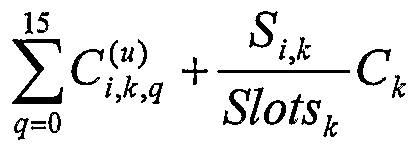
Finally, the total uplink capacity per terminal class, where there are several different types of terminal classes in an uplink beam, can be computed in step S4 as
where q=0...G-l corresponding to the G traffic classes, i denotes the uplink beam, k denotes carrier types (terminal classes), S,^ denotes the number of contention slots required, Slots is the number of data slots in a type k terminal carrier and C* is the capacity of a type k terminal carrier. Note that S^ is only used for UTs .
Downlink Capacity Estimation
[79] The approaches for estimating downlink capacity requirements for downlink beams are analogous to uplink capacity estimation. However, some differences exist in the treatment of traffic for each terminal class and multicast traffic. When estimating uplink capacity, the traffic for each terminal class must be aggregated separately. When estimating downlink capacity, aggregation by terminal class is not required. Multicast traffic identified by a multicast group is accounted once for the originating uplink beam; while it will be accounted separated for each downlink beam belonging to the same group.
[80] The following variables are used to describe downlink capacity estimations. All capacities are in Mbps and all computations assume that operator specified minimum, mean and peak capacity numbers have been converted to Mbps. Total capacities for the downlink beam:
• denotes aggregate traffic destined to downlink beamy' of traffic class q.
• rf) denotes aggregate traffic destined to downlink beamy. Leased Traffic:
• denotes leased traffic in the point-to-point sub-matrix, where i, j, k, l, 0, q denote source beam, destination beam, terminal class, leased traffic, default connection type and traffic class respectively.
• c "g ι,o,g denotes leased traffic in the multicast sub-matrix, where i, g, k, l, 0, q denote source beam, multicast group, terminal class, leased traffic, default connection type and traffic class respectively.
• ^j o,q denotes aggregate leased traffic destined to downlink beamy, where 1, 0, q denote leased traffic, default connection type and traffic class respectively. Circuit Switched Traffic:
• ^"j 2,n,q denotes circuit switched call arrival rate in the point-to-point sub-matrix, where i, j, k,2, n., q denote source beam, destination beam, terminal class, circuit switched traffic, connection type n and traffic class q respectively.
• ^i,g},2,n,q denotes circuit switched call arrival rate in the multicast sub-matrix, where i, g, k,2, n, q denote source beam, multicast group, terminal class, circuit switched traffic, connection type n and traffic class respectively.
• ^j d ,2,n, denotes aggregated circuit switched call arrival rate destined to downlink beamy, where 2, n, q denote circuit switched traffic, connection type n and traffic class respectively.
• ^j ,n,q denotes number of required circuit switched channels destined to downlink beamy, where 2, n, q denote circuit switched traffic, connection type n and traffic class respectively.
• R("'?) , r("'?) denote circuit switched call rate and average call duration corresponding to the connection type n assigned to traffic class q. Non-Real Time:
• W k,3,q denotes minimum data rate of non-real time traffic in the point-to-point sub-matrix, where i, j, k,3, q denote source beam, destination beam, terminal class, non-real time traffic, traffic class respectively.
• w,( ,g'^3,? denotes minimum data rate of non-real time traffic in the multicast sub- matrix, where i, g, k,3, q denote source beam, multicast group, terminal class, non-real time traffic, and traffic class respectively.
• iσ j'jk,i,q denotes variance of non-real time traffic rate in the point-to-point sub- matrix, where i, j, k,3, q denote source beam, destination beam, terminal class, non-real time traffic, and traffic class respectively.
• (σ"; ( g^3 ?)2 denotes variance of non-real time traffic rate in the multicast traffic matrix, where i, g, k,3, q denote source beam, multicast group, terminal class, non-real time traffic, and traffic class respectively.
• w?( ,iq denotes minimum total data rate of traffic destined to downlink beamy of terminal class k, and downlink class q
• ( j d q)2 denotes variance of total data rate of traffic destined to downlink beamy of terminal class k, and downlink class q
• εq d) denotes upper-limit on cell loss probability for downlink class q
Best Effort:
• Jul '!kA,q denotes mean data rate of Best Effort traffic in the point-to-point sub- matrix, where /, j, k,4, q denote source beam, destination beam, terminal class, Best Effort traffic, and traffic class respectively.
• Ml"gj >g denotes mean data rate of Best Effort traffic in the multicast sub-matrix, where i, g, k,4, q denote source beam, multicast group, terminal class, Best Effort traffic, and traffic class respectively.
• j 4,q denotes mean total data rate of Best Effort traffic destined to downlink beamy for terminal class k, and traffic class q.
• w< q denotes minimum data rate of Best Effort traffic in the point-to-point sub- matrix, where i, j, k, q denote source beam, destination beam, terminal class, and traffic class respectively.
• w ι,(>"j,'>κ>lq denotes minimum data rate of Best Effort traffic in the multicast sub- matrix, where i, g, k, q denote source beam, multicast group, terminal class, and traffic class respectively.
• w j)κ>q- denotes minimum total data rate of Best Effort traffic destined to downlink beamy for terminal class k, and traffic class q. [81] Similar to the uplink capacity estimation, it is necessary to obtain the downlink traffic requirements from the traffic matrix. The traffic class traffic inputs for a given downlink beam are obtained by summing over all uplink beams in the point-to-point sub-matrix and then adding all multicast traffic bounded for that downlink beam.
[82] The following steps outline the construction of the downlink traffic requirements:
[83] For leased traffic, summation over uplink beams is performed for all terminal classes. The aggregate leased traffic capacity requirement for downlink beam y and traffic class q is determined as:
where Hi(l,0) is the set representing all the multicast groups for leased traffic originating from uplink beam destined to traffic class q. {H,(1,0) I j e H, (1,0)} represents the set of multicast groups that have downlink beamy
" as one of its destinations.
[84] For circuit switched traffic, summation over uplink beams is performed for each circuit switched connection type. Traffic elements for a given circuit switched connection type can be combined by adding the connection arrival rates as follows:
where Hι(2,n) is the set representing all the multicast groups for circuit switched traffic of connection type n, originating from uplink beam i. {H
t(2,ή) \ j e H
l(2,ή)} represents the set of multicast groups that have downlink beam j as of its destinations. The aggregate circuit switched connection arrival rate is then used for capacity calculation.
[85] For non-real time traffic summation over uplink beams is performed for each non- real time traffic class and terminal class. Traffic elements for a given terminal class and traffic class can be combined by adding the minimum data rates and variances of the data rates as follow:
Hi(3,q) is the set representing all the multicast groups for non-real time traffic class q, originating from uplink beam i. {Hl (3, q) \ j e Hl (3, q)} represents the set of multicast groups that have downlink beamy as one of its destinations.
[86] For best effort traffic summation over uplink beams is performed for each Best
Effort traffic class and terminal class. Traffic elements for a given terminal class and traffic class can be combined by adding the average data rates:
Hi(4,q) is the set representing all the multicast groups for non-real time traffic class q, originating from uplink beam i. {H, (4, q) \ j e H, (4, q)} represents the set of multicast groups that have downlink beamy as one of its destination.
[87] Control and management traffic is assigned to priority queue 0. The traffic capacity will be estimated according to known procedures.
where <^is an operator specified scaling factor (reserved capacity).
Traffic Analysis Operation
[88] Thus, in accordance with the present invention, a process as illustrated in Fig.
5 is followed in order to provide a simple and straightforward determination of traffic in a broadband system. In first step SI 1, the traffic for each of the uplink beams is determined in accordance with the type of calculations defined above. Also, in a second step SI 2, which is illustrated as subsequent to step Sl l only for exemplary purposes but clearly may be conducted concurrently or before the determination of the traffic for the uplink beams, the traffic for the downlink beams is determined. In step SI 3, a traffic matrix is generated and the traffic is discriminated according to categories (terminal classes, gateway) and priorities in the cells of a traffic matrix. The traffic for each uplink beam is grouped according to destination, priority and data rate. Similarly, the traffic for each downlink beam is grouped according to priority and data rate in step SI 4. For each category, including source (GW or UT), priority and rate, in step SI 5, a model is applied and a traffic estimate according to the model is generated. This process is repeated for each uplink and downlink beam. Then, in step SI 6, the traffic estimates for each uplink and downlink beam are arithmetically processed in a simple manner, such as but not limited to averaging and summation. The result of that calculation is then stored in the NCC at step S17 as representative of the beam traffic. That result is used in system planning and for subsequent system reconfiguration in step SI 8.
[89] While the present invention has been described in terms of one or more preferred or exemplary embodiments, it is not limited thereto, but is to be defined in terms of the appended claims, as interpreted in accordance with applicable principles of law.