WO2001050224A2 - Methods and systems for accessing information and services on a computer network - Google Patents
Methods and systems for accessing information and services on a computer network Download PDFInfo
- Publication number
- WO2001050224A2 WO2001050224A2 PCT/US2000/032798 US0032798W WO0150224A2 WO 2001050224 A2 WO2001050224 A2 WO 2001050224A2 US 0032798 W US0032798 W US 0032798W WO 0150224 A2 WO0150224 A2 WO 0150224A2
- Authority
- WO
- WIPO (PCT)
- Prior art keywords
- computer
- user
- code
- tag
- readable medium
- Prior art date
Links
Classifications
-
- H—ELECTRICITY
- H04—ELECTRIC COMMUNICATION TECHNIQUE
- H04L—TRANSMISSION OF DIGITAL INFORMATION, e.g. TELEGRAPHIC COMMUNICATION
- H04L67/00—Network arrangements or protocols for supporting network services or applications
- H04L67/2866—Architectures; Arrangements
- H04L67/30—Profiles
- H04L67/306—User profiles
-
- G—PHYSICS
- G06—COMPUTING; CALCULATING OR COUNTING
- G06F—ELECTRIC DIGITAL DATA PROCESSING
- G06F16/00—Information retrieval; Database structures therefor; File system structures therefor
- G06F16/90—Details of database functions independent of the retrieved data types
- G06F16/95—Retrieval from the web
- G06F16/955—Retrieval from the web using information identifiers, e.g. uniform resource locators [URL]
-
- H—ELECTRICITY
- H04—ELECTRIC COMMUNICATION TECHNIQUE
- H04L—TRANSMISSION OF DIGITAL INFORMATION, e.g. TELEGRAPHIC COMMUNICATION
- H04L67/00—Network arrangements or protocols for supporting network services or applications
- H04L67/01—Protocols
- H04L67/02—Protocols based on web technology, e.g. hypertext transfer protocol [HTTP]
-
- H—ELECTRICITY
- H04—ELECTRIC COMMUNICATION TECHNIQUE
- H04L—TRANSMISSION OF DIGITAL INFORMATION, e.g. TELEGRAPHIC COMMUNICATION
- H04L67/00—Network arrangements or protocols for supporting network services or applications
- H04L67/01—Protocols
- H04L67/04—Protocols specially adapted for terminals or networks with limited capabilities; specially adapted for terminal portability
-
- H—ELECTRICITY
- H04—ELECTRIC COMMUNICATION TECHNIQUE
- H04L—TRANSMISSION OF DIGITAL INFORMATION, e.g. TELEGRAPHIC COMMUNICATION
- H04L67/00—Network arrangements or protocols for supporting network services or applications
- H04L67/01—Protocols
- H04L67/12—Protocols specially adapted for proprietary or special-purpose networking environments, e.g. medical networks, sensor networks, networks in vehicles or remote metering networks
-
- H—ELECTRICITY
- H04—ELECTRIC COMMUNICATION TECHNIQUE
- H04L—TRANSMISSION OF DIGITAL INFORMATION, e.g. TELEGRAPHIC COMMUNICATION
- H04L67/00—Network arrangements or protocols for supporting network services or applications
- H04L67/50—Network services
- H04L67/51—Discovery or management thereof, e.g. service location protocol [SLP] or web services
-
- H—ELECTRICITY
- H04—ELECTRIC COMMUNICATION TECHNIQUE
- H04L—TRANSMISSION OF DIGITAL INFORMATION, e.g. TELEGRAPHIC COMMUNICATION
- H04L67/00—Network arrangements or protocols for supporting network services or applications
- H04L67/50—Network services
- H04L67/52—Network services specially adapted for the location of the user terminal
-
- H—ELECTRICITY
- H04—ELECTRIC COMMUNICATION TECHNIQUE
- H04L—TRANSMISSION OF DIGITAL INFORMATION, e.g. TELEGRAPHIC COMMUNICATION
- H04L69/00—Network arrangements, protocols or services independent of the application payload and not provided for in the other groups of this subclass
- H04L69/30—Definitions, standards or architectural aspects of layered protocol stacks
- H04L69/32—Architecture of open systems interconnection [OSI] 7-layer type protocol stacks, e.g. the interfaces between the data link level and the physical level
- H04L69/322—Intralayer communication protocols among peer entities or protocol data unit [PDU] definitions
- H04L69/329—Intralayer communication protocols among peer entities or protocol data unit [PDU] definitions in the application layer [OSI layer 7]
Definitions
- the present invention is directed to the field of electronic commerce and, more particularly, to methods and systems for marketing products and services using a computer network.
- the Internet comprises a vast number of computers and computer networks that are interconnected through communication channels.
- Electronic commerce refers generally to commercial transactions that are at least partially conducted using the computer systems of the parties to the transactions. For example, a purchaser can use a personal computer to connect via the Internet to a vendor's computer. The purchaser can then interact with the vendor's computer to conduct the transaction.
- the acceptance and widespread use of electronic commerce depends, in large part, upon the ease-of-use of conducting such electronic commerce. If electronic commerce can be easily conducted, then even the novice computer user will choose to engage in electronic commerce. Therefore, it is important that techniques be developed to facilitate conducting electronic commerce.
- the Internet facilitates conducting electronic commerce, in part, because it uses standardized techniques for exchanging information. Many standards have been established for exchanging information over the Internet, such as electronic mail, Gopher, and the World Wide Web (“WWW”).
- the WWW service allows a server computer system (i.e., web server or web site) to send graphical web pages of information to a remote cSeijt computer system. The remote client computer system can then display the web pages.
- Each resource e.g., computer or web page
- URL Uniform Resource Locator
- a client computer system specifies the URL for that web page in a request (e.g., a HyperText Transfer Protocol ("HTTP”) request).
- HTTP HyperText Transfer Protocol
- the request is forwarded to the web server that supports that web page.
- that web server receives the request, it sends the requested web page to the client computer system.
- the client computer system receives that web page, it typically displays the web page using a browser.
- a browser is typically a special-purpose application program that effects the requesting of web pages and the displaying of web pages.
- the World Wide Web portion of the Internet is especially conducive to conducting electronic commerce.
- Many web servers have been developed through which vendors can advertise and sell products.
- the products can include items (e.g., music) that are delivered electronically to the purchaser over the Internet and items (e.g., books) that are delivered through conventional distribution channels (e.g., a common carrier).
- a server computer system may provide an electronic version of a catalog that lists the items that are available.
- a user who is a potential purchaser, may browse through the catalog using a browser and select various items that are to be purchased. When the user has completed selecting the items to be purchased, the server computer system then prompts the user for information to complete the ordering of the items.
- This purchaser-specific order information may include the purchaser's name, the purchaser's payment information (e.g., credit card number), and a shipping address for the order.
- the server computer system then typically confirms the order by sending a confirming web page to the client computer system and schedules shipment of the items.
- the user may type in a specific URL address in the "address" box of the browser program, or use a search engine and click on the selection found to be most appropriate.
- the user When typing in a new URL address, the user will have made the effort to either write down or memorize the URL address, and then correctly type the address into the "address" box without syntax or spelling errors. Both activities are troublesome, time consuming, and prone to human error. Failure to accomplish both correctly, however, will lead to a failed search or arrival at an undesired web site.
- search engine when using a search engine to reach a desired web site, the user types in a word or words of an item or topic for which the user wishes to search.
- the search engine will use the word or words specified, regardless of context, to generate a result from the engine's scans of the entire Internet. As there are million of web sites around the world, this search often results in thousands of options for a given search. The user is thus overloaded with seemingly appropriate options and often is unable to discover the actual web site that the user was truly searching for.
- Figure 1 is a schematic diagram illustrating components of an access system in one embodiment.
- Figure 2 is a flow diagram of a routine performed by application software for retrieving information and/or services from a server computer using the access system in one embodiment.
- Figure 3 is a flow diagram of a routine performed on a server computer for responding to a unique transaction code ("UTC") request in one embodiment.
- UTC unique transaction code
- Figure 4 is a flow diagram of a routine performed by application software for selecting between launching a local application or retrieving a URL from a remote server computer, in another embodiment.
- Figure 5 is a schematic diagram illustrating the assembly of a unique 10-byte RF reader code in one embodiment.
- Figure 6 is a schematic diagram illustrating the assembly of a UTC in one embodiment.
- Figure 7 is a flow diagram of a routine performed on a server computer for communicating with a network-enabled device in a secure mode in one embodiment.
- Figure 8 is a flow diagram of a routine performed on a user network- enabled device for communicating with a server computer in a secure mode in one embodiment.
- Figure 9 is a flow diagram of a routine performed by application software for retrieving information and/or services from a server computer using the access system in one embodiment.
- Figure 10 is a schematic diagram illustrating the assembly of an RF reader code in an alternative embodiment.
- Figure 11 is a schematic diagram illustrating the assembly of a registration RF tag code in an alternative embodiment.
- Figure 12 is a schematic diagram illustrating the assembly of a new user command code in an alternate embodiment.
- Figure 13 is a schematic diagram illustrating the assembly of a UTC in an alternate embodiment.
- Figure 14 is a schematic diagram illustrating the assembly of a unique 64-bit RF tag code in one embodiment.
- Figure 15 is a schematic diagram illustrating the assembly of a unique 256-bit RF tag code in one embodiment. DETAILED DESCRIPTION OF THE ILLUSTRATED EMBODIMENTS
- the access system allows a user to view a web page, download content (including streaming audio and video content), conduct a commercial transaction, or perform virtually any other Internet related activity by placing a computer-readable medium, such as a radio-frequency identification tag ("RF tag”), in the proximity of a computer-readable medium reader, such as a radio- frequency read/write device (“RF reader”), that communicates with the user's network-enabled device such as a computer.
- RF tag radio-frequency identification tag
- RF reader radio-frequency read/write device
- the user can obtain the desired information and/or service without having to search for the appropriate web site and without having to key the exact URL into the address box of a browser program.
- the computer-readable medium may include a magnetic medium, any laser-readable medium, and so on.
- an RF tag and RF reader are each encoded with unique codes that are also stored in a system server computer and entered into a look-up database table that links each unique code with a specific application, server, or web site URL.
- the RF tag can be embedded in a token, financial instrument, consumer product, promotional item, and so on for distributing to a consumer/user via a purchased product, advertising, or promotional activity.
- an RF reader can be given to users as a promotional item or it can be purchased by the user.
- Application software loaded on a network-enabled device of the user interfaces with the RF reader. Like the RF tag and RF reader, this application software can be purchased by the user or distributed (e.g., via the Internet) to the user for free as a promotional item.
- the user When the user wants to access resources such as information or services on a desired web site using the access system, the user places an appropriate RF tag in the proximity of the RF reader.
- the RF reader reads the unique code off of the RF tag, and sends the RF tag's unique code and, in one embodiment, the RF reader's code to the user's network-enabled device via a wired or wireless connection.
- the application software running on the user's network- enabled device receives the two unique codes and combines them into a single unique transaction code (UTC).
- UTC unique transaction code
- the application software then establishes access to the Internet or other suitable computer network, and sends the UTC via the network to the system server computer having the look-up database tables that map the code (i.e., the unique codes from the RF tag and the RF reader) to a specific application, server, or web site URL.
- the code i.e., the unique codes from the RF tag and the RF reader
- the system server computer then extracts the RF tag's unique code from the UTC and matches it against the codes in the look-up database tables.
- the system server computer sends, in one embodiment, the URL associated with that unique code to the application software on the user's network -enabled device.
- the application software receives this URL and directs a browser program on the network-enabled device to retrieve the information (e.g. , web page) or application associated with the URL. Once retrieved, the user is able to use the information or run the application to view the information, perform a desired commercial transaction, or any other activity.
- the access system can be used in various embodiments to provide the user with easy access to information or services.
- the RF tag can be encoded with a unique code that, rather than access a URL via a remote server computer, simply initiates a local application on the user's network-enabled device.
- a "simple RF tag" can be encoded with a unique code that contains a specific URL.
- the simple RF tag is placed in the proximity of the RF reader, and the reader reads the URL off of the RF tag and transmits this URL to the application software on the user's network-enabled device.
- the application software launches a browser program with the URL and retrieves the associated content or application for the user to view, download, or otherwise interact with.
- the "simple RF tag” embodiment there is no need for the application software to first access the system server computer to retrieve the URL, as the URL is encoded directly into the RF tag.
- RF tags can also be encoded with unique codes that cause the system server computer to perform transactions in a secure mode.
- the RF tag's unique code is linked to a security routine of the system server computer.
- the security routine directs the system server computer to request that the application software send it a password encoded on the RF tag. In one embodiment, this can be a 32-bit password, in other embodiments, the password can contain more or less than 32 bits of information.
- the system server computer receives the password from the application software and checks it for authenticity, the transaction is allowed to proceed and, in one embodiment, the system server computer sends a new password back to the application software.
- the application software can then direct the RF reader to write (assuming write capability) this new password onto the RF tag.
- the new password can then be used in subsequent secured transactions.
- a remote web server computer that receives a URL request from the application software can perform a secure password exchange routine that is substantially similar to the routine discussed above with reference to the system server computer.
- the web server computer would request the application software send it the 32-bit password encoded on the RF tag for verification of authenticity. After verification, the web server computer could send a new password back to the application software.
- the application software can then direct the RF reader to write (assuming write capability) this new password onto the RF tag. The new password can then be used in subsequent secured transactions. All password exchange communications between the application software and server computers can be in secure mode (e.g., SSL, PCT, or TLS).
- access system will be described in the general context of computer executable instructions, such as routines executed by a general-purpose computer, such as a personal computer.
- a general-purpose computer such as a personal computer.
- the access system can be practiced with other computer system configurations, including Internet appliances, hand-held devices, multiprocessor systems, microprocessor-based or programmable consumer electronics, network PCs, mini-computers, mainframe computers, and the like.
- the access system can be embodied in a special-purpose computer or data processor that is specifically programmed, configured or constructed to perform one or more of the computer-executable instructions explained in detail below.
- the access system can also be implemented in distributed computing environments where tasks or modules are performed by remote processing devices, which are linked through a wired or wireless communications network.
- FIG. 1 is a schematic diagram illustrating components of an access system in one embodiment.
- An access system 100 includes a uniquely coded radio- frequency identification tag 110 ("RF tag 110"), and a uniquely coded radio- frequency read/write device 120 ("RF reader 120").
- the RF reader 120 is capable of reading the unique radio-frequency code off of the RF tag 110, and writing information to the RF tag 110.
- the RF reader can be masked to only read RF codes off selected RF tags, in this way preventing the use of unauthorized or copied RF tags.
- the RF reader 120 transmits the RF tag's unique code, and its own unique code, to a user network-enabled device 130 ("user computer 130").
- the unique codes are transmitted to the user computer 130 via a wired connection.
- the RF reader connects to the user computer via a Universal Serial Bus (USB), and connects to the USB host as a Human Input Device (HID Class).
- the wired connection can be IEEE 1394, DVI, or PS/2.
- the unique codes are transmitted via a wireless connection.
- the wireless connection can be infrared (e.g., IrDA), or radio frequency (e.g., Bluetooth or HomeRF).
- the RF tag can be replaced by a suitable tag that uses a magnetic strip (such as a credit card), a bar code, or other method of encoding a computer readable medium. Accordingly, the RF reader can be replaced by a device suitable for reading and writing to the corresponding tag embodiment.
- the user computer 130 may include one or more central processing units or other logic processing circuitry, memory, input devices (e.g., keyboards and pointing devices), output devices (e.g., display devices and printers), and storage devices (e.g., fixed, floppy and optical disk drives), all well known but not shown in Figure 1.
- the user computer 130 may include a browser program module 134 ("browser 134") that allows the user computer 130 to access and exchange data with a computer network 140, including web sites within the World Wide Web portion of the Internet.
- the user computer 130 also includes an application software module 132 that performs the functions of reading the unique RF codes of the RF tag 110 and RF reader 120, writing information to the RF tag 110, and other routines associated with accessing information and services off of the computer network 140, as described in further detail below.
- the user computer 130 is connected via the computer network 140 to a system server computer 150 and a web server computer 160.
- the system server computer 150 performs many of the processes associated with the access system 100, and includes a look-up database table 152 that stores the unique codes from the RF tag 110 and RF reader 120.
- the look-up database table 152 maps each specific unique code to a specific application, server computer, or web site URL that is accessed via the computer network 140.
- the system server computer 150 also includes a server engine 151, a database management component 153, a web page database 154, a notification process component 156, and a transaction database 158, as well as other components not shown in Figure 1.
- the web server computer 160 includes a server engine 161, a database management component 163, and a web page database 164, as well as other components not shown in Figure 1.
- the web server computer 160 can store content and applications and distribute them via the computer network 140 to the user computer 130.
- the content can be in audio, video, or graphical format and the applications can perform commercial transactions or data management functions.
- concepts of the access system can be used in various environments other than the Internet or computer network environment depicted in Figure 1.
- the concepts can also be used in electronic mail environments in which the electronic mail messages may include the equivalent of a unique RF code, or an associated web page or URL.
- the information the user retrieves can be presented to the user as an email message, or as an email message with a hyperlink to a web site.
- Various communication channels other than the Internet may also be used, such as a local area network, a wide area network, or a point-to-point dial-up connection.
- Concepts of the access system may also be used in a single computer environment rather than a user/server environment.
- system server computer 150 may comprise any combination of hardware or software that can support these concepts.
- the access system server computer 150 may actually include multiple computers.
- the user network-enabled device 130 may comprise any combination of hardware or software that interacts with the system server computer 150 to perform the concepts of the access system disclosed herein.
- This user device may include television-based systems, and various other consumer products through which web pages may be accessed.
- computer-readable medium may be a device that sends its unique code as a telephonic tone when activated. The code may identify a web page and be used by a web-enabled phone to retrieve and display the web page.
- Figure 2 is a flow diagram of a routine 200 performed by the application software 132 for retrieving information and/or services from a server computer using the access system 100 in one embodiment.
- the routine 200 checks for the presence of the RF tag 110 in the proximity of the RF reader 120.
- decision block 204 if the RF tag 110 is not presently in the proximity of the RF reader 120, the routine 200 continues to check for the presence of an RF tag. If the RF tag 110 is in the proximity, then the routine 200 obtains the RF tag's unique code from the RF reader 120, as shown in block 206.
- this routine could be invoked when, or wait for, an event to be generated indicated that the RF tag is in proximity of RF reader.
- the routine 200 obtains the RF reader's unique code from the RF reader 120 as well.
- the routine 200 combines the unique codes from the RF tag 110 and the RF reader 120 and creates a unique transaction code (UTC).
- the routine 200 establishes a connection to the computer network 140 and sends the UTC via the computer network 140 to the system server computer 150.
- the routine 200 receives a corresponding URL back from the system server computer 150 via the computer network 140, as shown in block 214.
- the routine 200 launches the browser 134 with the URL received from the system server computer 150.
- the routine 200 can launch a local application program received from the system server computer 150 instead of the URL received in block 214. After performing block 216, the routine 200 loops to block 202 to wait for an RF tag.
- the browser 134 in block 216 sends the URL via the computer network 140 to the web server computer 160.
- the web server computer 160 responds by sending the appropriate web page back to the browser 134, which the browser 134 will then display on the user computer 130.
- the web server computer 160 can send audio or video content, or web pages formatted for commercial transactions or data management, to the browser 134.
- the application software 132 can also include a routine or routines that allow a user to use the access system without having to place an actual RF tag in the proximity of the RF reader.
- the server computer can provide a bitmap or code to the application software 132 for creating a graphic image of the RF tag on the user's network-enabled device.
- the application software 132 can then use the code in a directory routine that compiles, sorts, and displays a user's RF tags on the user's network-enabled device based on information contained in the RF tag's unique RF identification code.
- the RF tags can be sorted into different fields by different criteria, such as the shape of the RF tag, application type, date the RF tag was first used, color of the RF tag, etc.
- the RF tag can be graphically presented as a "virtual" RF tag and displayed on the user's network-enabled device. The user can then start a transaction as if the "real" RF tag was being used simply by "clicking on” the virtual RF tag in the directory.
- the server computer can also provide the application software 132 with an audio code for presenting an audible display whenever a particular RF tag is used. For example, a theme song or advertising jingle associated with a particular product can be audibly displayed when an RF tag associated with that product is used.
- the application software 132 can also include its own browser routine that can serve as the network navigation program, with pre-installed applications that can speed up, facilitate, and/or simplify usage of the access system when linked to the computer network 140.
- the application software can also display a greeting card that calls up humorous video clips, digital photo albums, birthday songs, etc. as an added dimension of the interactivity offered by the access system.
- the application software 132 can also include other facilities, such as look-up tables that map the unique identification codes of the RF tag 110 and RF reader 120 to specific applications, servers, or web site URLs. Compilation of user-specific information and data, such as web sites visited, transactions performed, and times used, can also be accomplished with the application software 132.
- Figure 3 is a flow diagram of a routine 300 performed by server software for responding to a UTC request in one embodiment.
- the routine 300 receives a UTC from a resource such as the application software 132.
- decision block 304 the routine 300 checks the UTC to determine if the UTC is valid. If not, the routine 300 sends an error message to the user computer 130, as shown in block 310. If the UTC is valid, the routine 300 extracts the RF tag's unique code from the UTC as shown in block 305.
- the routine 300 retrieves the URL corresponding to this code from the look-up database table 152 of the system server computer 150. The routine 300 then sends this URL to the resource that sent the UTC, such as the application software 132.
- the transaction in block 307 can be stored in the transaction database 158 of the system server computer 150, as shown in block 308. After performing block 308, the routine 300 loops to block 302 to receive a UTC.
- the routine 300 can extract the unique code for the RF reader 120 from the UTC sent to it by the application software 132. The routine 300 can then determine if the RF reader 120 is the most up-to-date version. If not, the routine 300 can send an appropriate message to the application software 132 for display to the user that indicates that an update to the RF reader 120 is advisable. In a similar process, the routine 300 can also check the version of application software 132 running on the user computer 130, and include a message recommending an update if the application software 132 is not found to be the most up-to-date version.
- the system server computer 150 can also perform other functions. For example, it can keep track of all RF tags used by a particular user, and/or record other personal user data. The server computer 150 can then organize this user data and perform data mining and data analysis operations with the compiled information. This information can then be accessed by commercial clients for marketing purposes when the client uses a dedicated authorization RF tag. As will be discussed below, the system server computer 150 is also able to initiate and terminate secure communications with the application software 132 and/or the web server computer 160. Included in the secure functions is the ability to verify the authenticity of the RF tag 110 via a password encoded on the RF tag, and the ability to provide a new password to be written to the RF tag 1 10 over the original password. In addition, the server computer 150 can also act as a host server for specific application web sites that are accessed by "simple" unlinked RF tags that are encoded with URLs.
- Figure 4 is a flow diagram of a routine 400 performed by the application software 132 for selecting between launching a local application or retrieving a URL from a remote server computer, in another embodiment.
- the type 1 RF tag is a read-only device without a password that can be used with the computer network 140 for non-secure applications like retrieving advertising, samplers of audio/video, or greeting cards.
- the type 2 RF tag can be read and written to, and contains a 32- bit password.
- the type 2 RF tag can be used with the computer network 140 for secure applications as it cannot be copied and it can only be authenticated by the application software 132 communicating with the system server computer 150 and/or web server computer 160.
- the type 3 RF tag can be read and written to and can be used for performing local applications on the user's network-enabled device without using the computer network 140.
- the type 3 RF tag can be used to display content such as a business card.
- the application software 132 obtains the RF tag 110's unique code sent to it by the RF reader 120.
- the unique code of the RF tag is checked to determine if the type of RF tag is a type 1, type 2 or type 3. If the RF tag is a type 3 RF tag, the application software 132 will begin a local application program on the user computer 130, as shown in block 404. In this embodiment, access via the computer network 140 to a remote server computer is not needed. After completing block 404, the routine 400 loops to checking for another RF tag in the proximity of the RF reader.
- the application software 132 obtains the unique code associated with the RF reader 120 as shown in block 406, and proceeds to retrieve a URL from a remote server computer in a method that can be similar to routine 200 depicted in Figure 2.
- various user-interface features can be incorporated into an RF tag and an RF reader.
- the shape of the RF tag such as a circle, oval, square, rectangle, triangle, zigzag, etc. can be mode-specific to a particular application.
- LED lights can be incorporated into the RF tag that light-up or flash when the RF tag is in use.
- the RF reader can incorporate lights that illuminate to show when it has been activated, that a transaction is in progress, that an Internet connection has been established, or conversely, that any of the related processes have failed. Sounds can also be incorporated to the RF reader to provide similar indications.
- the functionality of the RF reader can be incorporated into various peripheral devices commonly associated with network-enabled devices.
- this functionality can be embedded into a mouse controller, a mouse pad, a speaker, a screen monitor, a personal computer, a portable lap top computer, a portable electronic organizer, a digital mobile telephone, a portable audio device, a portable video device, a set-top box, an audio device, a TV-set, or a CD/DVD reader/writer.
- an RF tag storage device like an accordion file folder, CD-flip rack, or Rolodex, can be provided to organize the RF tags.
- An organizer that organizes the RF tags by shape, application, color, date, etc. can also be provided.
- FIG. 5 is a schematic diagram illustrating encoding of the RF reader 120 with a unique 10-byte identification code in one embodiment.
- the unique identification code 502 includes a manufacturer's authorization code portion 508, date portion 504, unique ID portion 512, and RF reader type portion 514.
- the date portion 504 contains day, month, and year fields as illustrated by blocks 504 and 506.
- the unique identification code 502 is generated and authorized by the system server computer 150 and is registered as "produced, but not in use yet" on the database management component 153 of the system server computer 150.
- this registration scheme provides a tracking mechanism to prevent unauthorized use of the access system: RF tag readers that use a registration code that is not produced yet will be unauthorized; and RF readers that use a code that is already in use (e.g., copies) will also be also unauthorized.
- FIG. 6 is a schematic diagram illustrating the assembly of a unique transaction code 602 ("UTC 602") by the application software 132 in one embodiment.
- the 160-bit UTC 602 is composed of three unique code portions 604, 606, and 608.
- the unique reader code portion 604 is associated with the RF reader 120 and contains 80 bits of code.
- the unique RF tag code portion 606 is associated with the RF tag 110 and contains 64 bits of code.
- the unique application software code portion 608 contains 16 bits of code that denotes the version of application software 132 that is running on the user computer 130.
- Figure 7 is a flow diagram of a routine 700 performed on a server computer for communicating with a network-enabled device in a secure mode in one embodiment.
- the access system can be performed in secure mode if desired to protect the interests of the parties involved in the transaction being conducted.
- the routine 700 can run on the system server computer 150 ( Figure 1). In other embodiments, the routine 700 can run on the web server computer 160 ( Figure 1).
- the routine 700 receives a UTC. Data in the look-up database table 152 of the system server computer 150 corresponding to the UTC indicates that a secure transaction is required, and the routine 700 sets up a secure connection via the computer network 140 ( Figure 1), as shown in block 702.
- a conventional method for setting up a secure connection can be used.
- the routine 700 sends an authentication request to the source of the UTC.
- the routine 700 receives a unique serial number and 32-bit password taken off of the RF tag 110 that initiated the transaction, in block 706.
- passwords with more or less than 32 bits can be used.
- the serial number and password are checked in decision block 708. If the serial number and password do not check out, an error message is returned, as shown in blocks 714 and 716. If the serial number and password do check out, then the routine 700 will look-up and retrieve a URL from the look-up database table 152 corresponding to the UTC received in block 701, as shown in block 710. This URL is then sent along with a new 32-bit password back to the source of the UTC in block 712. After completing block 712 or 716, routine 700 loops back to block 701 to receive a UTC.
- Figure 8 is a flow diagram of a routine 800 performing a secure transaction on a user network-enabled device in one embodiment.
- the routine 800 can be operating in conjunction with the routine 700 ( Figure 7) to receive a URL from a remote server in a secure transaction.
- the routine 800 receives a request for authentication from a server computer.
- the routine 800 sets up a secure connection to the server computer via the computer network 140.
- the routine 800 obtains the unique serial number and 32-bit password of the RF tag 110 using the RF reader 120.
- the routine 800 then sends the unique serial number and 32-bit password to the server computer via the computer network 140 using the secure connection, as shown in block 808.
- the routine 800 receives an indication from the server computer whether or not the serial number and 32-bit password were authenticated. If the serial number and password were not authenticated, an error message is displayed on the user computer 130 for the user as shown in block 811. If the serial number and password are authenticated, then the routine 800 will receive a new 32-bit password and the desired URL from the server computer, as shown in block 812. The routine 800 then writes the new 32-bit password to the RF tag 110 using the RF reader 120, as shown in block 814. In block 816, the routine 800 launches the browser 134 with the URL received in the secure mode from the server computer. After performing block 816 or 811, routine 800 loops back to block 801 to receive an authentication request from a server.
- Figure 9 is a flow diagram of a routine 900 performed by the application software 132 for retrieving information and/or services from a server computer using the access system 100 in an alternate embodiment.
- the RF tag is a "simple RF tag" that is encoded with a URL linking the RF tag to a web site that contains the desired information or service.
- the user computer 130 does not need to access the system server 150 to obtain the URL of the desired web site.
- the application software 132 simply obtains the URL directly from the simple RF tag and uses this URL to launch the browser module 134.
- the routine 900 determines if a simple RF tag is in the proximity of the RF reader 120.
- routine 900 continues to check for a tag. If the simple RF tag is in the proximity, the routine 900 obtains the URL from the simple RF tag using the RF reader 120. The routine 900 then launches the browser 134 with the URL to obtain the desired information and/or services from the associated web site, as shown in block 908. After completing block 908, routine 900 loops to block 902 to wait for an RF tag.
- Figure 10 is a schematic diagram illustrating an alternate embodiment of an RF reader code.
- the standard device descriptor 1002 of the RF reader contains two identification code portions that will describe the device, a two-byte product identification portion 1004, and a two-byte vendor identification portion 1006.
- the standard device descriptor 1002 will also contain two index code portions, a one- byte manufacturer index code portion 1008 will contain information describing the manufacturer, and a one-byte product index code portion 1010 will contain information about the specific reader.
- the foregoing alternate reader embodiment can be used in conjunction with a special registration RF tag as explained below.
- FIG. 11 is a schematic diagram illustrating a data structure 1100 of a registration RF tag in accordance with this embodiment.
- the data structure 1100 contains an eight-page portion 1102, wherein each page contains 32 bits of information.
- Page 0 contains a 32-bit serial number portion 1104 of the registration RF tag.
- Page 3 contains a 32- bit information portion 1110 that includes an eight-bit configuration portion 1111 and a 24-bit password portion 1113.
- the eight-bit configuration portion 1111 contains a one-bit Manchester code portion 1112, a two-bit RF tag mode portion 1114, a one-bit password mode portion 1116, and four other bits of read and/or write information 1118.
- FIG. 12 is a schematic diagram illustrating a new user command data structure 1200 in accordance with this embodiment.
- the new user command data structure 1200 has a 16-bit product identification portion 1202, a 16-bit vendor identification portion 1204, an eight-bit manufacturer information portion 1206, and a 16-bit application software version portion 1208.
- the 16-bit product identification portion 1202, the 16-bit vendor identification portion 1204, and the eight-bit manufacturer information portion 1206, all come from the code stored on the RF reader and are equivalent to the product identification portion 1004, the vendor identification portion 1006, and the manufacturer information portion 1008, respectively, shown in Figure 10 with respect to the RF reader.
- the 16-bit software version portion 1208 is provided by the application software. Once the application software has created the new user command data structure 1200, the application software sends this command and 32-bit registration number from the registration RF tag to the system server computer.
- the registration number of the registration RF tag is the 32-bit serial number portion 1104 of the registration RF tag data structure 1102, as shown in Figure 11.
- the system server computer When the system server computer receives the new user command and the RF tag registration number, it will validate the RF tag registration number and the reader and application software information in the new user command. If the information received by the server computer is validated, the server computer will send a URL of a registration site back to the application software. The application software will then direct a browser program to access the registration site using the URL. The accessed registration application will guide the user through the registration process by directing the user to fill in a web-based screen.
- the web page will offer three levels of registration to the user: Level 1 will be the minimum required information and will require only the name, gender, birthday, and email address of the user; Level 2 will additionally request the address of the user; and Level 3 will also request the marital status, educational degree, occupation, income, and phone number of the user.
- the server computer will send a confirmation back to the application software.
- the application software will then locally store the registration RF tag's registration number, which can also be referred to as a "user registration number".
- this user registration number can be retrieved from local storage for assembly of a unique transaction code (UTC).
- UTC unique transaction code
- the access system can also include alternate embodiments of the unique transaction code (UTC).
- UTC unique transaction code
- a user will start by placing an appropriate RF tag in the proximity of an RF reader.
- the RF reader reads the unique code off of the RF tag and sends the RF tag's unique code, and the RF reader's code, to the user's network-enabled device via a wired or wireless connection.
- the application software running on the user's network-enabled device receives the RF tag's unique code and the reader's code and combines them with the application software version code and, in this alternate embodiment, the user's registration number that has been locally stored on the user's network enabled device, to create a UTC.
- FIG. 13 is a schematic diagram illustrating the assembly of a UTC 1302 in accordance with the alternate method described in the preceding paragraph.
- the 128-bit UTC 1302 is composed of four code portions, a 16-bit reader identification portion 1304, a 32-bit user registration number portion 1306, a 64-bit unique RF tag code portion 1308, and a 16-bit application software version code portion 1310.
- the 16-bit reader identification code portion 1304 comes from the reader code, and is equivalent to the product identification portion 1004 as shown in Figure 10.
- the user registration number portion 1306 is the 32-bit serial number portion 1104 which originally came from the registration RF tag shown in Figure 11, and is subsequently stored on the user's network enabled device.
- the unique 64-bit RF tag code portion 1308 is taken from the particular RF tag that happens to be in use.
- the application software After creating the UTC, the application software establishes access to the Internet or other suitable computer network and sends the UTC via the network to the system server computer.
- the server computer Using a double look-up table format, the server computer will extract the user registration number 1306 from the UTC and authenticate the user's registration. If the user is validly registered, the server computer will access the second look-up table, extract the RF tag's unique code from the UTC, and compare the RF tag's unique code to the look-up table.
- the URL or application associated with the RF tag's unique code is then sent back to the application software. Once the application software receives the URL, the remaining processes for retrieving information or services using this alternate embodiment of the access system can be substantially similar to the processes explained above in accordance with Figures 1-9.
- Figure 14 is a schematic diagram illustrating the assembly of a unique 64-bit type 1 RF tag data structure 1402 in accordance with one such alternate embodiment.
- the 64-bit type 1 RF tag has a 40-bit unique code portion 1404 that is arranged in the structure of portion 1406 for use in the UTC.
- the RF tag code portion 1308 of the UTC shown in Figure 13 contains 64 bits of information, not 40. Therefore, there is a 24-bit reserved portion 1408 that is combined with the RF tag code portion 1406 to create the entire 64-bit RF tag code portion 1410 that is used with the UTC.
- FIG. 15 is a schematic diagram illustrating the assembly of a 256-bit type 2 RF tag data structure 1502 in accordance with an alternate embodiment.
- the 256-bit type 2 RF tag memory can include 256-bits of EEPROM organized into eight pages 1504 of 32 bits each.
- the 256-bit RF tag can contain a serial number portion 1512, a password portion 1514, a reserved portion 1516, and a configuration and password portion 1520.
- the 256-bit RF tag can also contain a unique 64-bit RF tag code portion 1506 on pages 4 and 5 that will be used to create the UTC. The relationship of the eight bytes contained in pages 4 and 5 to the UTC data structure is shown by the relationship portion 1508.
- Byte configuration 1530 represents one configuration that can be used for the various bytes of information contained in the data structure 1502.
- This byte configuration includes a one-bit Manchester code portion 1532, a two-bit RF tag mode portion 1534, a one-bit password mode portion 1536, and four one-bit read and/or write portions 1538.
- other RF tags with other data structures, memory capacity, and security features may be used to accomplish the same purpose as the type 2 RF tag.
- the access system disclosed in accordance with Figures 1-15 in its various embodiments can be used in commercial and non-commercial embodiments to download advertising and other content, perform transactions, or manage data on a computer network such as the Internet.
- a product seller may offer a free "limited usage” RF tag (e.g., good for three uses) or a free "clipped usage” RF tag (e.g., 60 seconds of an audio track) to distribute audio tracks, movie trailers, or video clips as a method of advertising its product.
- a user places the free RF tag in the proximity of the reader 120.
- the application software 132 obtains the unique codes off of the free RF tag and the RF reader 120, compiles a UTC, and sends the UTC via the computer network 140 to the system server computer 150. After extracting the free RF tag's unique code from the UTC, the system server computer 150 sends the corresponding URL from the look-up database table 152 to the application software 132. The browser 134 is then launched with this URL, and the advertising content retrieved from the web server 160 with the URL is displayed on the user's network-enabled device for the user to view.
- the access system can also be used in a substantially similar manner for pay-per-use sales of audio and video products.
- a user can purchase an RF tag permitting the user to download specific audio and/or video content.
- the RF tag can utilize a secure mode so that unauthorized users cannot access the content.
- the access system can be used to facilitate the download of paid-for software on a user's network-enabled device. The user purchases an RF tag from the seller of the online software and uses the RF tag on a network-enabled device to automatically retrieve and download the software that the user purchased.
- the RF tag could be used to provide the user access to peer- to-peer networks.
- the RF tag in these embodiments can be enabled with a decrementing device that decrements the number of uses of the RF tag.
- the RF tag can also include a display component that displays how many times the RF tag has been used to download the content, and/or how many more times the tag can be used.
- Radio content can also be accessed using the access system disclosed herein.
- a special RF tag is used that accesses the appropriate radio content on a server computer and plays the audio content on the user's network-enabled device.
- a user can listen to Internet radio stations using his or her own personal presets stored on the system server computer independent of the location of the user or the kind of network-enabled device being used.
- special radio station RF tags can locate and store new and interesting radio stations and programs.
- an RF tag vending machine or an RF tag kiosk can be located in various public places or stores for dispensing the RF tags to purchaser/users. These RF tags can be pre-encoded with unique codes linking them to various URLs and other resources, such that purchasers/users can select from the RF tags according to which tag provides the service, information, or content desired.
- the kiosk or vending machine can provide a system that enables the purchaser/user to personalize the RF tag by recording user specific links and other personal presets for the RF tag in the system server computer.
- "Blank" RF tags can also be stocked that are not yet printed with the various attributes that permit different types of network access.
- the vending machine or kiosk can be fitted with an RF tag read/write device so that a personalized user interface with personal presets can be encoded onto the RF tag by the user/purchaser.
- the vending machine can also be fitted with a camera, keyboard and/or microphone to further personalize the RF tag with personal audio recordings, a photograph, or a picture or video linked to the RF tag.
- the combination of the unique RF code and the selected attributes are embedded in the RF tag and the vending machine/kiosk will print the RF tag with appropriate graphics and distribute it to the user/purchaser.
- Payment for the various RF tags sold or dispensed through the vending machine or kiosk can be done either online (credit card, banking card) or offline (smart card, banking card or an RF tag prepaid debit card).
- the system server computer will store the link between the user's payment data and the unique RF tag identification code as a method for authenticating the user when the RF tag is subsequently used.
- shops, museums, and other establishments can be fitted with RF readers near products or venues of interest. When a selected RF tag is placed on such an RF reader, the information on the particular product or venue is stored on the system server computer's look-up database under the unique RF code of that particular RF tag. Later, the user can use the RF tag on any network-enabled device to access and display the product or venue information, to compare products, or take another (interactive) look at that museum exhibit at leisure.
- Unlinked RF tags are also available in an embodiment of the access system.
- This RF tag initially has no link to any application, URL, or transaction on the system server computer.
- a user Via a special sei'vice performed by the system server computer, a user can link the RF tag to specific content like a web site, piece of music, greeting card, picture, or movie.
- the system server computer instead of sending the application software a URL, the system server computer recognizes the RF tag's code as being one that is unlinked, and sends the user a request via the application software to visit a specific URL to make the desired links on the currently unlinked RF tag.
- the system server computer could send the application software a request to provide the linking desired by the user.
- this desired linking is then written to the RF tag by the RF reader.
- This service allows a user to immediately access the desired links anywhere that the user uses the RF tag.
- the personal links established by the user on the previously unlinked RF tag can also be edited subsequent to the initial linking to change the content or service accessed by the RF tag.
- the access system can also be used to store and categorize various data for a user or a business in another embodiment.
- the data of interest can be stored in a system server computer database under a unique RF code.
- an RF tag with that unique code is used on a network-enabled device, the data will be immediately retrieved.
- the system can be used to store details on an employee, medical patient, or other selected person to be recalled by the user independent of the location or network-enabled device used. This information can be used for security purposes, personnel records, or for personal information like gaming levels, stock portfolios, or frequently and/or last used phone numbers.
- the system can be used as a file/directory management device. Instead of searching archaic records and old electronic files, or trying to remember the file name that the document was saved under, business or personal documents can be linked with an RF tag for easy access and document management without having to go through the arduous task of finding a particular storage site.
- the access system can also be used to reduce on-time departure problems in public transit systems that may result from passengers not being aware of current departure status. For example, if a passenger is given a boarding pass that includes an RF tag, the passenger can use the RF tag at various kiosks located within a terminal to easily obtain current departure information. This relieves the passenger of relying on a public address system to obtain a change of departure information.
- the access system can also be used to create a user's personalized computing environment regardless of the remote network-enabled device that the user happens to be located at.
- the personalized computing office or information of the user is stored on the system server computer, and an RF tag is used to retrieve and display this personalized data on a remote network-enabled device.
- an RF tag can be encoded with personalized computer environment settings that can include choice of language, personal data like address books, and email addresses and software applications.
- the RF tag can also be used to provide the user with access to personal applications when using a remote network-enabled device.
- the access system can also facilitate advertising over a computer network in various embodiments.
- a company can distribute free RF tags to users whereby placing the RF tag in the presence of an RF reader takes the user directly to the target advertising information the company wants the user to see.
- the RF tag can be used to provide the user with almost instant access to an advertiser's on-line product catalogue. In this way, the user can research and compare the product in the comfort of the user's own home on his or her own time.
- the RF tags distributed to consumer users with direct links to advertising web sites can also include information directing the user to the nearest branch or outlet that sells the advertised products.
- the free RF tags can also permit recipient users to retrieve and download freeware onto the user network-enabled devices, wherein the content of the freeware contains advertising related to the company's products.
- the access system can also be used as a business card.
- a businessperson can create and distribute RF tag "business cards" to clients. When placed in the proximity of a reader, the businessperson's contact details and email address will immediately be displayed to the client.
- This RF tag embodiment can convey a great deal more information to the client than could be included on an ordinary business card.
- a pre-addressed email screen could also be displayed that would allow the client to contact the business person by simply typing a message and pressing "send.”
- an RF tag can be included when a user purchases a particular product. If needed later, the user can use the RF tag to bring up details on the product such as service information, specifications, safety records, logistics, user manuals, parts and service catalogs, or shipping and tracking information. In addition, this information can be linked to online purchases of other related items. Similarly, the RF tag can be linked to direct customer service support whenever the user has problems and/or questions regarding the product or service. Warranty registration can also be facilitated with the access system by using an RF tag to identify a product or service and allowing the purchaser of the product or service to perform the warranty registration procedures online with the RF tag from the purchaser's own network- enabled device.
- the RF tag can be used for product sales documentation in a substantially similar manner.
- an RF tag can be written with extra information at the point of purchase so that the product manufacturer, purchase date, purchase amount, sales outlets and other purchase specifics can be linked to the RF tag and stored on the system server computer. This guarantees that the customer always has access to the correct purchase information, product updates, frequently asked questions, etc.
- the point of purchase can also be fitted with an RF tag printer to further personalize the RF tag with pertinent purchase and/or product information.
- the access system can also provide useful authorization functions for Internet or other computer network-related transactions.
- financial institutions banks, brokers, e- commerce payment systems
- the RF tag can also be used to authorize an online email system, or as a prepaid debit card.
- an RF tag can be purchased with a value amount (e.g., in time, money, number of accesses, etc.) which can be deducted upon authorization. This amount can be stored on the RF tag itself or on the system server computer.
- the RF tag can be fitted with a small display that displays the amount of value left either on the RF tag itself or on a network-enabled device.
- an RF tag can be used with the access system as a gambling device that acts as a debit card that automatically deducts or adds credit to a gambler's account.
- the access system can also be used as a purchasing tool in alternate embodiments. For example, online services such as magazine subscriptions, market research, etc., can be purchased by a user by purchasing an RF tag that is linked to the selected content.
- the system can also be used to make Internet phone calls using a familiar user interface and personal presets independent of the location of the user or the kind of network-enabled device being used, by storing the user interface and presets on the system server computer and accessing them with an RF tag.
- the access system can be used to make videoconference calls using a familiar user interface with personal presets.
- the system can also be used by communication companies to offer a complete personalized phone or videoconference service using the RF tag as a calling card.
- the access system can also be used as a global positioning system (GPS) guide that directs a user to businesses and other services in one embodiment.
- GPS global positioning system
- the RF tag's unique code will direct the system server computer to send the user's network-enabled device the parameters of the location the user desires to go to.
- the user's network-enabled device can then use these parameters along with the current location parameters of the user (acquired from a typical GPS system) to provide the user with directions to the desired location - for example, a store, restaurant, or other service provider.
- the access system can be used to distribute coupons or other product information to a store customer.
- the customer could present an RF tag to an RF reader upon entering the store, or an RF tag carried on the customer's person could be automatically read by an RF reader as the customer enters the store.
- the RF tag could be read as the customer approaches selected products within the store.
- the server computer in response to receiving the RF tag's unique code, can cause a telephone call or page to be placed to the customer's cell phone that audibly displays product coupons or other product information to the customer.
- the server computer can cause paper coupons to be automatically printed-out for the customer to pick up at a kiosk located within the store.
- the RF reader 120 will be acceptance tested by an RF reader test unit.
- the RF reader 120 can be connected to this test unit with a USB connector.
- the test unit will check the hardware functionality, and a test RF tag will be used to make contact with the system server computer 150.
- the system server computer 150 will register a new RF reader code and send this new unique RF reader code to the RF reader's programmable memory via the test unit.
- the unique code associated with this particular RF reader 120 will then be stored on the database component of the server computer 150.
- the test unit will have secure connection to the server computer 150. Both the RF reader test unit and the test RF tag will be part of a manufacturing package that can be licensed to manufacturers of the access system components described in accordance with Figure 1.
- Chippo System for Personal Computer environments.
- the specification desc ⁇ bes PC Software attributes. Server applications, the protocol definition, types of transactions, types of Chippo tokens and Database setup.
- This specification is to be seen as a User Requirement Specification. It is intended that this specification will be accompanied by a Technical Requirement Specification.
- the Chippo svstem allows users to shortcut and simplify- their Internet activi ⁇ es by ehminaung die need to remember, type, or mouse click to a website or server.
- the users simply throws the Chippo on to the Chippo Reader, and the Chippo Application Software, via an Internet or network enabled device, will take the user directly to the desired website or server without the hassle ot typing, clicking or memorizing an URL address.
- the diagram below depicts the Chippo system and its mam components.
- USB interface • Runs Web Browser • Translates unique code
- the Chippo system consists of 4 main building blocks and 2 enabling blocks.
- PC Personal Computer
- the Chippo Reader will connect to the PC via USB.
- USB host It will connect to the USB host as a Human Input Device (HID Class).
- HID Class Human Input Device
- index codes of 1 byte each will point to information about the manufacturer of the reader and product specific information:
- the string will be 1 byte allowing 256 different manufacturers iProduct
- Chippo tokens come in three different versions: the 64-bit version, the 256-bit version and the 2048-bit version.
- Chippo Tokens are also referred to as "Chippos”.
- the 64 bit Chippos are mainly used for non-secure applications like advertising, samplers of Audio/Video, greeting cards, etc
- Chippos are used for applications that require security. These Chippos can not be copied and can be authenticated by the CHAPP software and the applications running on the Chippo server and the customer server.
- the 2048 bit Chippos will be used to distribute data for off-line use like business cards.
- the specification of these Chippos is not part of this document.
- the Chippo data of 40 bits will be part of the Unique Transaction Code (UTQ that will be sent to the Chippo Server.
- the 16 remaining bits reserved in the UTC for Chippo info will be set to "0" (Byte 15 - 17).
- Coding of the 40 bits will be decided on a per case basis.
- the coding of the 64 bit Chippos will be agreed with the supplier.
- a separate document will specify the rules for protecting these codes.
- the memory of this Chippo consists of 256 bits EEPROJM and is organized in 8 pages of 32 bits each. Depending on the operation mode the configuration of these pages and the content of Pages 4-7 can differ.
- the 256 Bit Chippo can operate in different modes for the different applications.
- the present Chippo applications will use the following configuration setting'
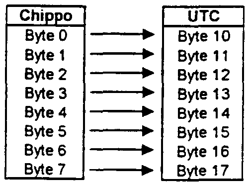
- Page 4 and 5 contain the code that will be part of the UTC to be sent to the Chippo Server.
- the translation is as follows:
- CHAPP will communicate with the server to send and receive commands.
- the CHAPP software and the server software will use the following commands:
- CHAPP will send the Unique Transaction Code (UTC) of 136 bits containing 4 codes plus parameters to the Chippo Server:
- the Server will send a URL plus parameters to the CHAPP software
- CHIPPO STOP command will be send to the Chippo server if it was requested bv the server in the parameters of the TRANSACTION START command.
- CHAPP will send the Unique Transaction Code (UTC) of 128 Bits containing 4 codes plus parameters to the Chippo Server
- the Server will send this command to CHAPP once it has received the CHIPPO STOP command.
- the command includes a URL (WWW chippo Com) and a parameter byte.
- CHAPP Once CHAPP is installed and a reader is connected for the first time. CHAPP will ask the user to put on the registration Chippo. CHAPP will read the User Registration Number from the Chippo and send the ⁇ New User> command to the server comprising die data below. The server will respond with the "user registration" command.
- CHAPP will await the confirmation by die server and once received it will store the user registration number on the PC's HDD for use in all future UTCs.
- the server will check the validity of die reader information, the CHAPP version and the user registration number.
- the user registration number is the unique 32 bits serial number of the H ⁇ tag2 Chippo.
- the server will send back the URL of the Chippo Reader Registration site.
- the Server will send a URL plus parameters to the CHAPP software Parameters:
- CHAPP will read the Chippo code from the token and create the UTC by getting the stored User Registrauon Number, the Chippo Reader Code (is idProduct) and the version of the CHAPP Software. This will be sent to the server.
- the server will send back a URL and a parameter byte.
- CHAPP will start the browser (if not already running) and will give an indication on the reader via the LED's.
- CHAPP will send the UTC -r parameters indicating this is a Stop command to the Chippo Sen'er once a Chippo is being removed from the reader. CHAPP will only do this if this was requested by the Server in the ⁇ TRANSACTION START> command. 3. TRANSACTION STOP>, Sen-er to CHAPP.
- the Server will send this command to CHAPP once it has received the CHIPPO STOP command.
- the command includes a URL (WWW.chippo.com) and a parameter byte.
- CHAPP will send a ⁇ NEW USER> command to the sen'er.
- CHAPP will await the confirmation by the sen-er and once received it will store the user registration number on the PC's HDD for use in all future UTCs.
- the sen-er will check the validity of the reader information, the CHAPP version and the user registration number.
- the sen-er will send back the URL of the Chippo Reader Registration site.
- the registration application will guide the user through the registrauon process. See Chapter 8.3 User Registration Information.
- CHAPP can now locally store the user registration number.
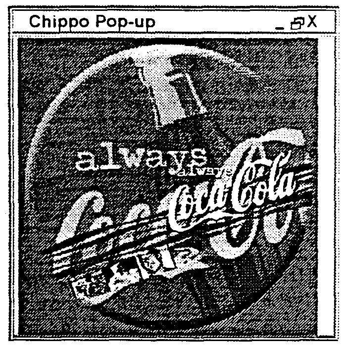
- the Sen-er will send a URL plus parameters to the CHAPP software with a field to indicate this is a pop-up ad URL.
- the ad should appear on top of the other windows.
- CHAPP When the CHAPP logo on the Windows taskbar is double clicked CHAPP will display a window containing the following buttons:
- CHAPP will be installed from a CDRO.M, this CDROM contains:
- the registration Chippo is used when registering yourself as a new user or when you want to change/update your registration info. It will also provide entrance to the Chippo.com site for personalized sen-ices.
- the registration Chippo is a 256 bit (Philips H ⁇ tag2) Chippo.
- serial number in page 0 of the tag will be used as the user's registration numb er.
- Pages 4 to 7 will contain the following code when delivered to the user:
- the Chippo Sen'er Architecture contains two main Databases
- the Routing application main functions:
- Routing Apphcauon and the Look-up table are of high importance: they determine the speed with which the consumer's browser is redirected to the corresponding web site.
- CHAPP will create and send the UTC to the sen * er.
- the roudng application will lookup the URL and the parameters that correspond to the UTC. This will be sent back to CHAPP via the TRANSACTION START>, Sen-er to CHAPP, command.
- the Sen'er will send this command to CHAPP once it has received the ⁇ CHIPPO STOP> command.
- the command includes the WWW.chippo.COIT! URL and a Darameter bvte. 3. ⁇ USER REGISTRATION ⁇ Sen-er to CHAPP
- the sen-er will check die validity of tin; reader information, the CHAPP version and the user registration number.
- the sen-er will send back the URL of the Chippo Reader Registration site.
- the registration application will guide the user through the registration process. See Chapter 8.3 User Registration Information.
- the sener will send back the ⁇ USER REGISTRATION ⁇ command as a confirmation to CHAPP.
- CHAPP can now locally store the user registration number.
- the Sen-er will send a URL plus parameters to the CHAPP software with a field to indicate tins is a pop-up ad URL.
- the ad should appear on top of the other windows.
- the Chippo Database keeps a log file that contains all transactions done with Chippos. Combined with the User Registrauon Information this provides an enormous amount of usage information.
- the User Registration Application registers users during die CHAPP & reader installation process by filling in a web-based screen. It will receive 9 bytes from CHAPP describing the idProduct, ldVendor, iManufacturer and the 32 bits user registration number. The application will check if the ldVendor and the user registration number are valid. Ttie id ⁇ ' endor is a fixed code linked to Chippo Technologies and issued by the USB IF. The User Registration Number is a unique 32 bits code generated by Philips Semiconductors. The code received from CHAPP should be in between two values that we will receive Philips. Once checked by die sen-er CHAPP will store the user registration number on the PC's HDD. On the sen-er the registration information is stored in the Chippo Database.
- the web application will gather the following information to be stored in the Chippo Database.
- the web page will offer three levels of registration:
- the pop-up advertising application can send a specific transaction command to CHAPP.
- CHAPP will re-direct the browser to display an advertising frame on top of the Browser ' s main screen. See CHAPP-Sen r er Communication Protocol.
- index codes of 1 byte each will point to information about the manufacturer of the reader and product specific information: l.Manufacturer : will point to a string descriptor describing the manufacturer the string will be 1 byte allowing 256 different manufacturers lProduct : will pcrint to a string descriptor containing product specific information, this will include the full part number of 5 Bytes (hex-dec). The full content of the string is to be defined
- Chippo Reader Manufacturing unit Chiippo Reader Manufacturing unit
- the Reader will be hooked up to the CRM bv the USB connector.
- the CRM will check die hardware functionality and will check the standard device descriptor.
- a Manufacturing Authorization Chippo Token will be used to make contact with the Chippo Sen-er.
- the sen-er will authenticate the Chippo Token and the Chippo Reader.
- the CRM will have a secure connection to the Chippo Sen-er. Bodi the CRM and the Manufacturing Chippo will be part of the manufacturing package and potential licensing package.
- the user registration system will provide protection on two levels:
- USB IF USB Implementers Forum
- the User Registration Number is identical to the serial number of the User Registration Chippo token. This number is issued by Philips Semiconductors. Copies of these tokens and/or their unique serial numbers will be in conflict with Philips Semiconductors.
- CHAPP Chippo serial number and password
- CHAPP will send this to the customer application and as a response CHAPP will receive back a new password which needs to be written to the Chippo.
- the sen'er can authenticate the Chippo by two means:
- the customer sen'er sets up a secure connection to the consumers PC (e.g. via SSL).
- the CHAPP software Upon request of the customer sen'er the CHAPP software will deliver the 32-bit unique se ⁇ al number and the 32-bit password recorded on the Chippo to the customer application (customer app). Once authenticated the customer app will send back to CHAPP the new password to be recorded on the Chippo and the transaction can take place.
Abstract
Description


Claims
Priority Applications (2)
| Application Number | Priority Date | Filing Date | Title |
|---|---|---|---|
| AU20578/01A AU2057801A (en) | 2000-01-04 | 2000-12-04 | Methods and systems for accessing information and services on a computer network |
| EP00983873A EP1428141A2 (en) | 2000-01-04 | 2000-12-04 | Methods and systems for accessing information and services on a computer network |
Applications Claiming Priority (4)
| Application Number | Priority Date | Filing Date | Title |
|---|---|---|---|
| US17443600P | 2000-01-04 | 2000-01-04 | |
| US60/174,436 | 2000-01-04 | ||
| US20684200P | 2000-05-24 | 2000-05-24 | |
| US60/206,842 | 2000-05-24 |
Publications (2)
| Publication Number | Publication Date |
|---|---|
| WO2001050224A2 true WO2001050224A2 (en) | 2001-07-12 |
| WO2001050224A3 WO2001050224A3 (en) | 2004-04-01 |
Family
ID=26870220
Family Applications (1)
| Application Number | Title | Priority Date | Filing Date |
|---|---|---|---|
| PCT/US2000/032798 WO2001050224A2 (en) | 2000-01-04 | 2000-12-04 | Methods and systems for accessing information and services on a computer network |
Country Status (3)
| Country | Link |
|---|---|
| EP (1) | EP1428141A2 (en) |
| AU (1) | AU2057801A (en) |
| WO (1) | WO2001050224A2 (en) |
Cited By (16)
| Publication number | Priority date | Publication date | Assignee | Title |
|---|---|---|---|---|
| WO2004003829A1 (en) | 2002-06-26 | 2004-01-08 | Nokia Corporation | Device for directing the operation of a user's personal communication apparatus |
| WO2004012412A2 (en) * | 2002-07-25 | 2004-02-05 | Yee James D | System and method for providing computer services |
| WO2004040793A1 (en) | 2002-10-31 | 2004-05-13 | Nokia Corporation | Method and system for selecting data items for service requests |
| EP1583000A3 (en) * | 2004-04-02 | 2005-12-28 | Swisscom Mobile AG | Method by means of which an end device can retrieve from a EPC Network pieces of information associated to EPC Codes. |
| US7212119B2 (en) | 2004-06-29 | 2007-05-01 | Nokia Corporation | Provision of feedback to users of communication devices |
| US7352999B2 (en) | 2004-01-29 | 2008-04-01 | Nokia Corporation | Terminal, method and computer program product for interacting with a service provider via a signaling tag |
| FR2911751A1 (en) * | 2007-01-18 | 2008-07-25 | Tagattitude Sa | Telecommunication method for providing e.g. short message service, to mobile telephone user, involves generating data from activation link of page for emitting data at short range by terminal to personal equipment before data transmission |
| EP1953673A2 (en) * | 2005-03-16 | 2008-08-06 | Samsung Electronics Co., Ltd. | Wireless terminal and RFID system for providing additional information and a method for providing additional information using wireless terminal and RFID system |
| EP1873681A3 (en) * | 2006-07-01 | 2008-10-01 | Leuze electronic GmbH + Co. KG | RFID-System |
| US7493082B2 (en) | 2004-05-12 | 2009-02-17 | Nokia Corporation | Methods, apparatus and computer program instructions for enhancing service discovery at a mobile terminal |
| US7752451B2 (en) | 2003-11-21 | 2010-07-06 | Jan Chipchase | System and method for virtual entity access |
| US8010621B2 (en) | 2005-10-11 | 2011-08-30 | Nokia Corporation | Offline webpage activated by reading a tag |
| US20120326847A1 (en) * | 2011-06-23 | 2012-12-27 | Hugo Strauman | Secure tag management method and system |
| EP2575058A1 (en) * | 2011-09-27 | 2013-04-03 | Casio Computer Co., Ltd. | Application generation apparatus, application generation method, and computer-readable recording medium |
| US9398137B2 (en) | 2005-04-19 | 2016-07-19 | Nokia Technologies Oy | Method, device and system for controlling application launching in a mobile terminal device |
| USRE48868E1 (en) | 2003-10-16 | 2021-12-28 | Nokia Technologies Oy | Terminal, method and computer program product for interacting with a signaling tag |
Citations (4)
| Publication number | Priority date | Publication date | Assignee | Title |
|---|---|---|---|---|
| US5375244A (en) * | 1992-05-29 | 1994-12-20 | At&T Corp. | System and method for granting access to a resource |
| EP0837406A2 (en) * | 1996-08-02 | 1998-04-22 | Symbol Technologies, Inc. | Data retrieval system and method |
| US5838252A (en) * | 1996-09-09 | 1998-11-17 | Datalink Systems, Inc. | Interactive two-way pager systems |
| US5974447A (en) * | 1996-07-17 | 1999-10-26 | Motorola, Inc. | Method and system for coupling a selective call receiver to widely distributed information sources |
-
2000
- 2000-12-04 WO PCT/US2000/032798 patent/WO2001050224A2/en not_active Application Discontinuation
- 2000-12-04 AU AU20578/01A patent/AU2057801A/en not_active Abandoned
- 2000-12-04 EP EP00983873A patent/EP1428141A2/en not_active Withdrawn
Patent Citations (4)
| Publication number | Priority date | Publication date | Assignee | Title |
|---|---|---|---|---|
| US5375244A (en) * | 1992-05-29 | 1994-12-20 | At&T Corp. | System and method for granting access to a resource |
| US5974447A (en) * | 1996-07-17 | 1999-10-26 | Motorola, Inc. | Method and system for coupling a selective call receiver to widely distributed information sources |
| EP0837406A2 (en) * | 1996-08-02 | 1998-04-22 | Symbol Technologies, Inc. | Data retrieval system and method |
| US5838252A (en) * | 1996-09-09 | 1998-11-17 | Datalink Systems, Inc. | Interactive two-way pager systems |
Non-Patent Citations (1)
| Title |
|---|
| ARBANOWSKI S ET AL: "Service personalization for unified messaging systems" COMPUTERS AND COMMUNICATIONS, 1999. PROCEEDINGS. IEEE INTERNATIONAL SYMPOSIUM ON RED SEA, EGYPT 6-8 JULY 1999, LOS ALAMITOS, CA, USA,IEEE COMPUT. SOC, US, 6 July 1999 (1999-07-06), pages 156-163, XP010555030 ISBN: 0-7695-0250-4 * |
Cited By (21)
| Publication number | Priority date | Publication date | Assignee | Title |
|---|---|---|---|---|
| WO2004003829A1 (en) | 2002-06-26 | 2004-01-08 | Nokia Corporation | Device for directing the operation of a user's personal communication apparatus |
| WO2004012412A2 (en) * | 2002-07-25 | 2004-02-05 | Yee James D | System and method for providing computer services |
| WO2004012412A3 (en) * | 2002-07-25 | 2004-04-29 | James D Yee | System and method for providing computer services |
| WO2004040793A1 (en) | 2002-10-31 | 2004-05-13 | Nokia Corporation | Method and system for selecting data items for service requests |
| EP1556965A1 (en) * | 2002-10-31 | 2005-07-27 | Nokia Corporation | Method and system for selecting data items for service requests |
| EP1556965A4 (en) * | 2002-10-31 | 2011-06-22 | Nokia Corp | Method and system for selecting data items for service requests |
| USRE48868E1 (en) | 2003-10-16 | 2021-12-28 | Nokia Technologies Oy | Terminal, method and computer program product for interacting with a signaling tag |
| US7752451B2 (en) | 2003-11-21 | 2010-07-06 | Jan Chipchase | System and method for virtual entity access |
| US7352999B2 (en) | 2004-01-29 | 2008-04-01 | Nokia Corporation | Terminal, method and computer program product for interacting with a service provider via a signaling tag |
| EP1583000A3 (en) * | 2004-04-02 | 2005-12-28 | Swisscom Mobile AG | Method by means of which an end device can retrieve from a EPC Network pieces of information associated to EPC Codes. |
| US7493082B2 (en) | 2004-05-12 | 2009-02-17 | Nokia Corporation | Methods, apparatus and computer program instructions for enhancing service discovery at a mobile terminal |
| US7212119B2 (en) | 2004-06-29 | 2007-05-01 | Nokia Corporation | Provision of feedback to users of communication devices |
| EP1953673A3 (en) * | 2005-03-16 | 2008-12-10 | Samsung Electronics Co., Ltd. | Wireless terminal and RFID system for providing additional information and a method for providing additional information using wireless terminal and RFID system |
| EP1953673A2 (en) * | 2005-03-16 | 2008-08-06 | Samsung Electronics Co., Ltd. | Wireless terminal and RFID system for providing additional information and a method for providing additional information using wireless terminal and RFID system |
| US9398137B2 (en) | 2005-04-19 | 2016-07-19 | Nokia Technologies Oy | Method, device and system for controlling application launching in a mobile terminal device |
| US8010621B2 (en) | 2005-10-11 | 2011-08-30 | Nokia Corporation | Offline webpage activated by reading a tag |
| US8650264B2 (en) | 2005-10-11 | 2014-02-11 | Nokia Corporation | Offline webpage activated by reading a tag |
| EP1873681A3 (en) * | 2006-07-01 | 2008-10-01 | Leuze electronic GmbH + Co. KG | RFID-System |
| FR2911751A1 (en) * | 2007-01-18 | 2008-07-25 | Tagattitude Sa | Telecommunication method for providing e.g. short message service, to mobile telephone user, involves generating data from activation link of page for emitting data at short range by terminal to personal equipment before data transmission |
| US20120326847A1 (en) * | 2011-06-23 | 2012-12-27 | Hugo Strauman | Secure tag management method and system |
| EP2575058A1 (en) * | 2011-09-27 | 2013-04-03 | Casio Computer Co., Ltd. | Application generation apparatus, application generation method, and computer-readable recording medium |
Also Published As
| Publication number | Publication date |
|---|---|
| EP1428141A2 (en) | 2004-06-16 |
| AU2057801A (en) | 2001-07-16 |
| WO2001050224A3 (en) | 2004-04-01 |
Similar Documents
| Publication | Publication Date | Title |
|---|---|---|
| AU762674B2 (en) | System and method for identification and streamlined access to online services | |
| US8280435B2 (en) | Communication system, settlement management apparatus and method, portable information terminal and information processing method, and program | |
| US5937158A (en) | System and method for connecting portable media with network and computer for use with the system | |
| US20020184183A1 (en) | Personalized media service | |
| US20020073025A1 (en) | Virtual experience of a mobile device | |
| US20020002488A1 (en) | Locally driven advertising system | |
| WO2001050224A2 (en) | Methods and systems for accessing information and services on a computer network | |
| US20010003177A1 (en) | Printed medium activated interactive communication | |
| US20010042016A1 (en) | Local portal | |
| US20020184092A1 (en) | Customized advertising methods for personal media services | |
| US8392329B2 (en) | Method and apparatus for facilitating purchase transactions across a network | |
| US20020184093A1 (en) | Controlled customized advertising methods in media | |
| US20090053992A1 (en) | Systems and methods for ordering and delivering digital content | |
| KR20010008101A (en) | A electronic business system using an identification number of a hardware and a business method using the same | |
| CA2488469A1 (en) | Advertising sales management system | |
| US20080109535A1 (en) | Point of sale device configuration systems and methods | |
| US20120323792A1 (en) | Multi platform and operating system digital content vending, delivery, and maintenance system | |
| US20020042758A1 (en) | Method and system for ordering and downloading digital content with unique identity recognition through a network | |
| US20020194135A1 (en) | System and method for providing e-services | |
| US20070022366A1 (en) | Methods and apparatus for providing web site creation services | |
| CN1578216B (en) | Information transmitting apparatus and method, information receiving apparatus and method, and information providing system | |
| JP3787479B2 (en) | Member registration system | |
| KR20150121746A (en) | Product information transmission system using near field communication and method thereof | |
| KR100365521B1 (en) | Sales system and method in internet | |
| JP2001344478A (en) | System and method for article purchase by internet shopping, broker server, and recording medium with recorded article purchase program |
Legal Events
| Date | Code | Title | Description |
|---|---|---|---|
| AK | Designated states |
Kind code of ref document: A2 Designated state(s): AE AG AL AM AT AU AZ BA BB BG BR BY BZ CA CH CN CR CU CZ DE DK DM DZ EE ES FI GB GD GE GH GM HR HU ID IL IN IS JP KE KG KP KR KZ LC LK LR LS LT LU LV MA MD MG MK MN MW MX MZ NO NZ PL PT RO RU SD SE SG SI SK SL TJ TM TR TT TZ UA UG US UZ VN YU ZA ZW |
|
| AL | Designated countries for regional patents |
Kind code of ref document: A2 Designated state(s): GH GM KE LS MW MZ SD SL SZ TZ UG ZW AM AZ BY KG KZ MD RU TJ TM AT BE CH CY DE DK ES FI FR GB GR IE IT LU MC NL PT SE TR BF BJ CF CG CI CM GA GN GW ML MR NE SN TD TG |
|
| 121 | Ep: the epo has been informed by wipo that ep was designated in this application | ||
| DFPE | Request for preliminary examination filed prior to expiration of 19th month from priority date (pct application filed before 20040101) | ||
| WWE | Wipo information: entry into national phase |
Ref document number: 2000983873 Country of ref document: EP |
|
| REG | Reference to national code |
Ref country code: DE Ref legal event code: 8642 |
|
| WWP | Wipo information: published in national office |
Ref document number: 2000983873 Country of ref document: EP |
|
| NENP | Non-entry into the national phase |
Ref country code: JP |
|
| WWW | Wipo information: withdrawn in national office |
Ref document number: 2000983873 Country of ref document: EP |