WO1997019723A1 - Apparatus and method to treat a disease process in a luminal structure - Google Patents
Apparatus and method to treat a disease process in a luminal structure Download PDFInfo
- Publication number
- WO1997019723A1 WO1997019723A1 PCT/US1996/019084 US9619084W WO9719723A1 WO 1997019723 A1 WO1997019723 A1 WO 1997019723A1 US 9619084 W US9619084 W US 9619084W WO 9719723 A1 WO9719723 A1 WO 9719723A1
- Authority
- WO
- WIPO (PCT)
- Prior art keywords
- balloon
- radiation
- lumen
- guidewire
- fluid
- Prior art date
Links
Classifications
-
- A—HUMAN NECESSITIES
- A61—MEDICAL OR VETERINARY SCIENCE; HYGIENE
- A61N—ELECTROTHERAPY; MAGNETOTHERAPY; RADIATION THERAPY; ULTRASOUND THERAPY
- A61N5/00—Radiation therapy
- A61N5/10—X-ray therapy; Gamma-ray therapy; Particle-irradiation therapy
- A61N5/1001—X-ray therapy; Gamma-ray therapy; Particle-irradiation therapy using radiation sources introduced into or applied onto the body; brachytherapy
- A61N5/1002—Intraluminal radiation therapy
-
- A—HUMAN NECESSITIES
- A61—MEDICAL OR VETERINARY SCIENCE; HYGIENE
- A61B—DIAGNOSIS; SURGERY; IDENTIFICATION
- A61B17/00—Surgical instruments, devices or methods, e.g. tourniquets
- A61B17/22—Implements for squeezing-off ulcers or the like on the inside of inner organs of the body; Implements for scraping-out cavities of body organs, e.g. bones; Calculus removers; Calculus smashing apparatus; Apparatus for removing obstructions in blood vessels, not otherwise provided for
- A61B2017/22051—Implements for squeezing-off ulcers or the like on the inside of inner organs of the body; Implements for scraping-out cavities of body organs, e.g. bones; Calculus removers; Calculus smashing apparatus; Apparatus for removing obstructions in blood vessels, not otherwise provided for with an inflatable part, e.g. balloon, for positioning, blocking, or immobilisation
- A61B2017/22065—Functions of balloons
- A61B2017/22068—Centering
-
- A—HUMAN NECESSITIES
- A61—MEDICAL OR VETERINARY SCIENCE; HYGIENE
- A61M—DEVICES FOR INTRODUCING MEDIA INTO, OR ONTO, THE BODY; DEVICES FOR TRANSDUCING BODY MEDIA OR FOR TAKING MEDIA FROM THE BODY; DEVICES FOR PRODUCING OR ENDING SLEEP OR STUPOR
- A61M25/00—Catheters; Hollow probes
- A61M25/10—Balloon catheters
- A61M2025/1043—Balloon catheters with special features or adapted for special applications
- A61M2025/1047—Balloon catheters with special features or adapted for special applications having centering means, e.g. balloons having an appropriate shape
-
- A—HUMAN NECESSITIES
- A61—MEDICAL OR VETERINARY SCIENCE; HYGIENE
- A61M—DEVICES FOR INTRODUCING MEDIA INTO, OR ONTO, THE BODY; DEVICES FOR TRANSDUCING BODY MEDIA OR FOR TAKING MEDIA FROM THE BODY; DEVICES FOR PRODUCING OR ENDING SLEEP OR STUPOR
- A61M25/00—Catheters; Hollow probes
- A61M25/10—Balloon catheters
- A61M2025/1043—Balloon catheters with special features or adapted for special applications
- A61M2025/1081—Balloon catheters with special features or adapted for special applications having sheaths or the like for covering the balloon but not forming a permanent part of the balloon, e.g. retractable, dissolvable or tearable sheaths
-
- A—HUMAN NECESSITIES
- A61—MEDICAL OR VETERINARY SCIENCE; HYGIENE
- A61N—ELECTROTHERAPY; MAGNETOTHERAPY; RADIATION THERAPY; ULTRASOUND THERAPY
- A61N5/00—Radiation therapy
- A61N5/10—X-ray therapy; Gamma-ray therapy; Particle-irradiation therapy
- A61N5/1001—X-ray therapy; Gamma-ray therapy; Particle-irradiation therapy using radiation sources introduced into or applied onto the body; brachytherapy
- A61N5/1007—Arrangements or means for the introduction of sources into the body
- A61N2005/1008—Apparatus for temporary insertion of sources, e.g. afterloaders
-
- A—HUMAN NECESSITIES
- A61—MEDICAL OR VETERINARY SCIENCE; HYGIENE
- A61N—ELECTROTHERAPY; MAGNETOTHERAPY; RADIATION THERAPY; ULTRASOUND THERAPY
- A61N5/00—Radiation therapy
- A61N5/10—X-ray therapy; Gamma-ray therapy; Particle-irradiation therapy
- A61N5/1001—X-ray therapy; Gamma-ray therapy; Particle-irradiation therapy using radiation sources introduced into or applied onto the body; brachytherapy
- A61N2005/1019—Sources therefor
- A61N2005/1021—Radioactive fluid
-
- A—HUMAN NECESSITIES
- A61—MEDICAL OR VETERINARY SCIENCE; HYGIENE
- A61N—ELECTROTHERAPY; MAGNETOTHERAPY; RADIATION THERAPY; ULTRASOUND THERAPY
- A61N5/00—Radiation therapy
- A61N5/10—X-ray therapy; Gamma-ray therapy; Particle-irradiation therapy
- A61N2005/1092—Details
- A61N2005/1094—Shielding, protecting against radiation
-
- A—HUMAN NECESSITIES
- A61—MEDICAL OR VETERINARY SCIENCE; HYGIENE
- A61N—ELECTROTHERAPY; MAGNETOTHERAPY; RADIATION THERAPY; ULTRASOUND THERAPY
- A61N5/00—Radiation therapy
- A61N5/10—X-ray therapy; Gamma-ray therapy; Particle-irradiation therapy
- A61N5/1001—X-ray therapy; Gamma-ray therapy; Particle-irradiation therapy using radiation sources introduced into or applied onto the body; brachytherapy
- A61N5/1007—Arrangements or means for the introduction of sources into the body
Definitions
- the present invention relates to an apparatus and a method to treat a disease process in a luminal structure.
- a structure includes, but is not limited to, veins, arteries, bypass grafts, prostheses, the gastrointestinal (GI) tract, the biliary tract, the genitourinary (GU) tract, and the respiratory tract (e.g. the tracheobronchial tree) .
- GI gastrointestinal
- GU genitourinary
- respiratory tract e.g. the tracheobronchial tree
- PCTA Percutaneous transluminal coronary angioplasty
- the process involves the insertion of balloon catheters through the femoral artery to the targeted coronary artery. Injection of radio-opaque contrast into the proximal coronary artery allows fluoroscopic localization of stenosed coronary segments. Balloon catheters are advanced to the site of stenosis over extremely thin guide wires to position the catheter at the point of occlusion. The distal end of the catheter contains a balloon which is inflated for 2-4 minutes to the full diameter of the occluded artery, decreasing the blockage and improving blood flow.
- PTCA restenosis after arterial intervention in general, PTCA in particular, seem to be primarily due to medial smooth muscle cell proliferation.
- Conventional PTCA is performed using a balloon catheter such an over-the-wire type catheter manufactured, for example, by Scimed Life Systems, Inc, of Maple Grove, Minnesota or a mono-rail type catheter manufactured, for example, by Advanced Cardiovascular Systems, Inc, of Temecula, California.
- Fig. 1 depicts such a conventional over-the-wire balloon catheter 1.
- the conventional balloon catheter 1 is utilized in an angioplasty procedure as follows. A conventional guidewire 2 is inserted into the patient's artery until the distal end of the guidewire 2 is past a target area (not shown) of the artery (not shown) where there is a buildup of material.
- the conventional balloon catheter 1 has a lumen 3 running therethrough.
- the guidewire 2 is inserted into the distal end of the balloon catheter 1 and the balloon catheter 1 is advanced over the guidewire until the balloon section la of the balloon catheter 1 is adjacent the buildup of material.
- the balloon section la is then inflated by an inflation means (not show) connected to an inflation port lb to clear the artery. Finally, the balloon section la is deflated, the balloon catheter 1 is pulled back up the guidewire and removed and the guidewire is likewise removed from the patient's artery.
- the first design class an arterial stent type device, is designed for long term deployment within the artery. Such a stent, if designed to emit radiation, would be in place long after the time necessary for the prevention of smooth muscle cell proliferation at the arterial site.
- United States Patent No. 5,059,166 to Fischell describes such a long term stent.
- the second design class for restenosis preventing devices contemplates the delivery of unspecified doses of radiation via radioactive catheters and guidewires. These devices utilize a movable, flexible radiation shield. However, it is questionable whether such a radiation shield could be constructed given the thickness of material required to shield the radiation source and the flexibility required to allow delivery of the radiation source and shield to the coronary site.
- United States Patent No. 5,213,561 to Weinstein relates to a device of this class.
- neither class of devices addresses the need to isolate the radioactive source from contact with the patient's body fluids.
- brachytherapy involves the placement of a radioactive source within tissue to deliver localized radiation and is frequently applied to treat recurrent disease in an area previously treated by external beam radiation.
- Blind-end catheters may be used to deliver radiation to tumors in the esophagus, trachea, or rectum, for example.
- Advantages include the sparing of critical structures close to the tumor, and brevity of treatment (hours to days) . Difficulties primarily involve anatomic constrains on implant placement.
- Common applications include the endoluminal treatment of recurrent endobronchial and bile duct tumors, the intracavitary treatment of cervical and endometrial cancer, and interstitial implants in unrespectable tumors with catheters or radioactive seeds.
- intervention includes, but is not limited to, balloon angioplasty, atherectomy, stent placement, arterial grafts, and arteriovenous fistula.
- hemodialysis therapy is complicated by thrombosis of both hemodialysis grafts and native shunts.
- Late graft failure (after about 6 weeks) is commonly associated with anatomic stenosis at the venous anastomosis, within the graft, or more proximally in the central venous system. Irradiation of the proliferative tissue from an intravascular source will inhibit the development of shunt outflow stenosis and thus decrease the incidence of thrombosis from the ensuing low flow state. Any proliferative tissue at the site of a vascular graft would also be amenable to this treatment.
- structure or structures include, but are not limited to, veins, arteries, bypass grafts, vascular prostheses, the gastrointestinal (GI) tract, the biliary tract, the genitourinary (GU) tract, and the respiratory tract (e.g. the tracheobronchial tree) .
- the diseases to be treated by the invention include proliferative diseases (both malignant and non-malignant) .
- an apparatus guided by a guidewire within a patient's artery for reducing restenosis after arterial intervention in the patient's artery comprising a radiation dose delivery wire with a radiation source encapsulated within its distal end, and a balloon catheter with a blind lumen sealed at its distal end and a guidewire lumen extending therethrough to accept said guidewire, said blind lumen being adapted to accept said radiation delivery wire into its proximal end.
- an apparatus inserted into a sheath in a patent's artery and guided by a guidewire within the patient's artery for reducing restenosis after arterial intervention in the patient's artery comprising a radiation dose delivery wire with a radiation source encapsulated within its distal end, and a balloon catheter with a blind lumen sealed at its distal end and a guidewire lumen extending therethrough to accept said guidewire, said blind lumen being adapted to accept said radiation dose delivery wire into its proximal end, said balloon catheter being adapted to be inserted into said sheath.
- an apparatus guided by a guidewire within a patient's artery for reducing restenosis after arterial intervention in the patient's artery comprising a radiation dose delivery wire with a radiation source encapsulated within its distal end, and a balloon catheter with a blind lumen sealed at its distal end and a guidewire lumen extending partially through said balloon catheter, said blind lumen being adapted to accept said radiation dose delivery wire into its proximal end, said guidewire lumen having an entry port located at a distal end of said balloon catheter and an exit port located upon a circumferential surface of said balloon catheter.
- an apparatus for reducing restenosis after arterial intervention in a patient's artery comprising a guidewire for insertion into the patient's artery at least as far as a target area of the artery, a radiation dose delivery wire with a radiation source encapsulated within its distal end, and a balloon catheter with a blind lumen sealed at its distal end and a guidewire lumen extending therethrough to accept said guidewire, said blind lumen being adapted to accept said radiation delivery wire into its proximal end.
- an apparatus guided by a guidewire within a patient's artery for reducing restenosis after arterial intervention in the patient's artery comprising a radiation dose delivery wire with a radiation source encapsulated within its distal end, and a catheter with a blind lumen sealed at its distal end and a guidewire lumen extending therethrough to accept said guidewire, said blind lumen being adapted to accept said radiation delivery wire into its proximal end.
- an apparatus to be inserted into a catheter for reducing restenosis after arterial intervention in a patient's artery comprising a radiation dose delivery wire with a radiation source encapsulated within its distal end, and a blind lumen open at its proximal end and sealed at its distal end, said blind lumen being adapted to accept said radiation dose delivery wire into its proximal end and to be inserted into said catheter.
- a method of reducing restenosis after arterial intervention in a patient's artery comprising inserting a guidewire into the patient's artery until a distal end of the guidewire is at least as far into the artery as a predetermined section of the artery, inserting the guidewire into a guidewire lumen of a balloon catheter with a blind lumen, inserting the balloon catheter with the blind lumen into the patient's artery at least as far as the predetermined section of the artery, inserting a radiation dose delivery wire into said blind lumen in said balloon catheter, moving said radiation dose delivery wire a predetermined distance into the blind lumen of the balloon catheter for a predetermined period of time, and removing said radiation dose delivery wire from said blind lumen of said balloon catheter after said predetermined period of time.
- an apparatus for use with a guidewire for reducing restenosis after arterial intervention in a patient's artery comprising a balloon catheter with a guidewire lumen extending therethrough adapted to accept a guidewire for guiding the balloon catheter in the patient's artery, said balloon catheter having a radiation producing coating on an internal surface.
- the radiation producing coating may include a material selected from the group consisting of Al-26, Sn-123, K-40, Sr-89, Y-91, Ir-192, Cd-115, P-32, Rb-86, 1-125, Pd-103, and Sr-90, or any other material selected from Tables 2 or 3, for example.
- the radiation producing coating may comprise a lacquer, a glue, an acrylic, vinyl, or an absorbing compound.
- the balloon portion of the catheter may be formed of a medical plastic material such as polyethylene, PET, and nylon.
- an apparatus for use with a guidewire for reducing restenosis after arterial intervention in a patient's artery comprising a balloon catheter with a guidewire lumen extending therethrough adapted to accept a guidewire for guiding the balloon catheter in the patient's artery, said balloon catheter having a radiation producing coating on an exterior surface.
- the radiation producing coating may include a material selected from the group consisting of Al-26, Sn-123, K-40, Sr-89, Y-91, Ir-192, Cd-115, P-32, Rb-86, 1-125, Pd-103, and Sr-90, or any other material selected from Table 2, for example.
- the radiation producing coating may comprise a lacquer, a glue, an acrylic, or a vinyl.
- the balloon catheter may be formed of a plastic material chosen from the group consisting of polyethylene, PET, and nylon.
- an apparatus for use with a guidewire for reducing restenosis after arterial intervention in a patient's artery comprising a balloon catheter with a guidewire lumen extending therethrough adapted to accept a guidewire for guiding the balloon catheter in the patient's artery, said balloon catheter being formed of a flexible material including a radiation producing source.
- the flexible material may be formed of a plastic material such as polyethylene, PET, and nylon.
- the plastic material may be doped with said radiation producing source.
- the radiation producing source may be chemically bonded to said plastic material by a covalent bond.
- the radiation producing source may be bonded to said plastic material by an ionic bond.
- the radiation producing source may be bonded to said plastic material by a biotin-avidin link.
- the radiation producing source may be bonded to said plastic material by coextrusion.
- a method for reducing restenosis after arterial intervention in a patient's artery comprising inserting a balloon catheter with a fluid delivery port connected thereto into the patient's artery and inserting a radioactive fluid into the balloon catheter through the fluid delivery port.
- the radioactive fluid may be selected from the group consisting of fluids containing Cu-61, Se-73, Co-55, Sc-44, Sr-75, Kr-77, Ga-68, In-110, Br-76, Ga-66, Ga-72, Sb-122, Na-24, Si-31, Ge-77, Ho-166, Re-188, Bi-212, Y-90, K-42, Ir-192, 1-125, Pd-103, Sr-90, and radioactive sodium- chloride, or any other chemical compound formulated from the isotopes given in Table 3, for example.
- an apparatus guided by a guidewire within a patient's artery for receiving a radiation dose delivery wire with a radiation source encapsulated within its distal end and for reducing restenosis after arterial intervention in the patient's artery comprising a balloon catheter with a blind lumen sealed at its distal end and a guidewire lumen extending therethrough to accept said guidewire, said blind lumen being adapted to accept said radiation delivery wire into its proximal end.
- an apparatus guided by a guidewire within a luminal structure of a patient for treating a disease process comprising a radiation dose delivery wire with a radiation source attached to its distal end; a balloon catheter with a blind lumen sealed at its distal end and a guidewire lumen extending therethrough to accept said guidewire; said blind lumen being adapted to accept said radiation delivery wire into its proximal end; and means for moving the distal end of said radiation dose delivery wire to a predetermined position within said blind lumen for a predetermined period of time.
- an apparatus guided by a guidewire within a luminal structure of a patient for treating a disease process comprising a radiation dose delivery wire with a radiation source attached to its distal end; a balloon catheter with a blind lumen sealed at its distal end and a guidewire lumen extending therethrough to accept said guidewire; said blind lumen being adapted to accept said radiation dose delivery wire into its proximal end; and a radiation blocking shield movable between the radiation source within the patient's luminal structure and a user of the apparatus.
- an apparatus inserted into a sheath in a luminal structure of a patient and guided by a guidewire within the patient's luminal structure for treating a disease process comprising a radiation dose delivery wire with a radiation source attached to its distal end; a balloon catheter with a blind lumen sealed at its distal end and a guidewire lumen extending therethrough to accept said guidewire; said blind lumen being adapted to accept said radiation dose delivery wire into its proximal end; said balloon catheter being adapted to be inserted into said sheath; and means for providing a liquid-tight seal between the radiation dose delivery wire and the proximal end of the blind lumen.
- an apparatus guided by a guidewire within a luminal structure of a patient for treating a disease process comprising a radiation dose delivery wire with a radiation source attached to its distal end; and a balloon catheter with a blind lumen sealed at its distal end and a guidewire lumen extending partially through said balloon catheter; said blind lumen being adapted to accept said radiation dose delivery wire into its proximal end; said guidewire lumen having an entry port located at a distal end of said balloon catheter and an exit port located upon a circumferential surface of said balloon catheter.
- an apparatus guided by a guidewire within a luminal structure of a patient for treating a disease process comprising a radiation dose delivery wire with a radiation source attached to its distal end; and a catheter with a blind lumen sealed at its distal end and a guidewire lumen extending therethrough to accept said guidewire; said blind lumen being adapted to accept said radiation dose delivery wire into its proximal end.
- an apparatus with a catheter to be inserted into a luminal structure of a patient for treating a disease process comprising a radiation dose delivery wire with a radiation source attached to its distal end; and a blind lumen open at its proximal end and sealed at its distal end; said blind lumen being adapted to accept said radiation dose delivery wire into its proximal end and to be inserted into said catheter.
- an apparatus for use with a guidewire inserted in a luminal structure of a patient for treating a disease process comprising a balloon catheter with a guidewire lumen extending therethrough adapted to accept a guidewire for guiding the balloon catheter in the patient's luminal structure; said balloon catheter having a radiation producing coating on an internal surface.
- an apparatus for use with a guidewire inserted into a luminal structure of a patient for treating a disease process comprising a balloon catheter with a guidewire lumen extending therethrough adapted to accept a guidewire for guiding the balloon catheter in the patient's luminal structure; said balloon catheter having a radiation producing coating on an exterior surface.
- an apparatus for use with a guidewire inserted into a luminal structure of a patient for treating a disease process comprising a balloon catheter with a guidewire lumen extending therethrough adapted to accept a guidewire for guiding the balloon catheter in the patient's luminal structure; said balloon catheter being formed of a flexible material including a radiation producing source.
- a method for treating a disease process in a luminal structure of a patient comprising inserting a balloon catheter with a fluid delivery port connected thereto into the patient's artery; inserting a radioactive fluid into the balloon catheter through the fluid delivery port.
- an apparatus guided by a guidewire within a luminal structure of a patient for receiving a radiation dose delivery wire with a radiation source on its distal end and for treating a disease process comprising a balloon catheter with a blind lumen sealed at its distal end and a guidewire lumen extending therethrough to accept said guidewire; said blind lumen being adapted to accept said radiation delivery wire into its proximal end.
- an apparatus for use with a guidewire inserted into a luminal structure of a patient for treating a disease process comprising a radiation dose delivery wire with a radiation source attached to its distal end; and a balloon catheter with a blind lumen sealed at its distal end a guidewire lumen extending therethrough adapted to accept a guidewire for guiding the balloon catheter in the patient's luminal structure; said blind lumen being adapted to accept said radiation dose delivery wire into its proximal end.
- an apparatus for use with a sheath and a guidewire inserted into a luminal structure of a patient for treating a disease process comprising a radiation dose delivery wire with a radiation source attached to its distal end; and a balloon catheter with a blind lumen sealed at its distal end and a guidewire lumen extending therethrough adapted to accept a guidewire for guiding the balloon catheter in the patient's luminal structure; said blind lumen being adapted to accept said radiation dose delivery wire into its proximal end; said balloon catheter being adapted to be inserted into a sheath in the patient's luminal structure surrounding said guidewire.
- an apparatus inserted into a luminal structure of a patient for treating a disease process comprising a guidewire for insertion into the patient's luminal structure at least as far as a target area of the luminal structure; a radiation dose delivery wire with a radiation source attached to its distal end; and a balloon catheter with a blind lumen sealed at its distal end and a guidewire lumen extending therethrough to accept said guidewire; said blind lumen being adapted to accept said radiation delivery wire into its proximal end.
- a method of treating a disease process in a patient comprising inserting a guidewire into a luminal structure of the patient until a distal end of the guidewire is at least as far into the luminal structure as a predetermined section of the luminal structure; inserting the guidewire into a guidewire lumen of a balloon catheter with a blind lumen; inserting the balloon catheter with the blind lumen into the patient's luminal structure at least as far as the predetermined section of the luminal structure; inserting a radiation dose delivery wire into said blind lumen in said balloon catheter; moving said radiation dose delivery wire into said blind lumen in said balloon catheter; moving said radiation dose delivery wire a predetermined distance into the blind lumen of the balloon catheter for a predetermined period of time; and removing said radiation dose delivery wire from said blind lumen of said balloon catheter after said predetermined period of time.
- a method for reducing restenosis after arterial intervention in a patient's artery comprising inserting a balloon catheter with a fluid delivery port connected thereto into the patient's artery, and inserting a radioactive fluid into the balloon catheter through the fluid delivery port, said radioactive fluid being selected from the group consisting of radioisotopes that decay with emission of beta plus or beta minus radiation, that have a half-life of between approximately 1 and 72 hours, that have an average decay energy of approximately 500-2000keV, and that have radiation intensity of greater than or equal to approximately 50%, said radiation intensity being measured in % per decay.
- the radioisotopes may be non- iodine and non-phosphorus based.
- an apparatus for reducing restenosis after arterial intervention in a patient's artery comprising a balloon catheter with a fluid delivery port connected thereto, and a radioactive fluid inserted into the balloon catheter through the fluid delivery port, said radioactive fluid being selected from the group consisting of radioisotopes that decay with emission of beta plus or beta minus radiation, that have a half-life of between approximately 1 and 72 hours, that have an average decay energy of approximately 500-2000keV, and that have radiation intensity of greater than or equal to approximately 50%, said radiation intensity being measured in % per decay.
- the radioisotopes may be non-iodine and non-phosphorus based.
- a dual-balloon catheter for treating a disease process in a luminal structure of a patient comprising an inner balloon, an outer balloon substantially concentric with and substantially surrounding the inner balloon, an inner balloon fluid delivery lumen in fluid connection with the inner balloon, and an outer balloon fluid delivery lumen in fluid connection with the outer balloon.
- a method for treating a disease process in a luminal structure of a patient comprising inserting into the luminal structure a dual-balloon catheter including an inner balloon, an outer balloon substantially concentric with and substantially surrounding the inner balloon, an inner balloon fluid delivery lumen in fluid connection with the inner balloon, and an outer balloon fluid delivery lumen in fluid connection with the outer balloon, and inserting a radioactive fluid into at least one of the inner balloon and the outer balloon through the inner balloon fluid delivery lumen and the outer balloon fluid delivery lumen, respectively.
- an indiflator for inserting fluid into a balloon catheter comprising an elongated tube for holding the fluid, the elongated tube having a first end and a second end, the first end of the elongated tube having a wall across the tube with a port therein for providing a fluid passage between an interior of the tube and an exterior of the tube, a plunger assembly including a plunger head with a first face and a second face and a plunger stem having first and second ends, the plunger head being adapted to slide within the tube and being connected to the first end of the plunger stem, lock means disposed at the second end of the tube for accepting and releasably locking the plunger stem, the second end of the plunger stem being disposed outside the tube, and a pressure valve disposed adjacent the second end of the plunger stem and being operatively connected to a pressure transducer on the second face of the plunger head facing the first end of the tube, whereby the pressure valve displays a pressure in an area of
- Fig. 1 shows the construction of a conventional over-the- rail type balloon catheter
- Fig. 2 shows the construction of a balloon catheter according to a first embodiment of the present invention
- Fig. 3 shows a cross-section of the balloon catheter according to the first embodiment of the present invention
- Fig. 4 shows the construction of a radiation dose delivery wire of the present invention
- Fig. 5 shows the construction of a second embodiment of the present invention
- Fig. 6 shows the construction of a third embodiment of the present invention
- Fig. 7 shows the construction of a fourth embodiment of the present invention.
- Fig. 8 shows the construction of a fifth embodiment of the present invention.
- Fig. 9 shows the construction of a sixth embodiment of the present invention.
- Fig. 10 shows the construction of a seventh embodiment of the present invention
- Fig. 11 shows dose versus distance for Ir-192, 1-125, Pd- 103, P-32, and Sr-90;
- Fig. 12 shows dose asymmetry (defined as maximum/minimum dose to vessel wall) resulting from inaccurate centering of 5mm long P-32, Sr-90, or Ir-192 sources within arteries of 3 and 5mm diameter;
- Fig. 13 shows a comparison of dose asymmetry for Sr-90 and Ir-192 sources of 5 and 30mm length in a 3mm diameter vessel
- Fig. 14 shows radial dose distribution for P-32 wires of 0.65 and 1.3mm diameter, and for a 3mm diameter P-32 balloon;
- Fig. 15 shows the construction of a radiation dose delivery wire in another embodiment of the present invention.
- Fig. 16 shows the construction of a radiation dose delivery wire in yet another embodiment of the present invention.
- Fig. 17 shows a cross-section of a dual-balloon catheter according to another embodiment of the present invention.
- Fig. 18 shows a cross-section of an indiflator according to an embodiment of the invention for use with a balloon catheter
- Fig. 19 shows the cross-section of a shield for use with the indiflator of Fig. 18
- Fig. 20 shows a cross-section of a lumen according to an embodiment of the invention for use with a balloon catheter;
- Fig. 21 shows a schematic drawing of a 3-way stopcock according to an embodiment of the invention for use with an indiflator and a balloon catheter;
- Fig. 22 shows a case for a 3-way stopcock according to an embodiment of the invention for use with an indiflator and a balloon catheter;
- Fig. 23 shows a container according to an embodiment of the invention for holding a radioactive fluid
- Fig. 24 shows another container according to an embodiment of the invention for holding a radioactive fluid
- Fig. 25 shows another container according to an embodiment of the invention for holding a radioactive fluid
- Fig. 26 shows a flexible plastic shield according to an embodiment of the instant invention.
- an apparatus guided by a guidewire within a patient's artery for reducing restenosis after arterial intervention in the patient's artery comprising a radiation dose delivery wire with a radiation source encapsulated within its distal end, and a balloon catheter with a blind lumen sealed at its distal end and a guidewire lumen extending therethrough to accept said guidewire, said blind lumen being adapted to accept said radiation delivery wire into its proximal end.
- the apparatus may further comprise means for providing a liquid-tight seal between the radiation dose delivery wire and the proximal end of the blind lumen.
- the means for providing a liquid-tight seal may comprise a liquid-tight radiation delivery wire port connected to the proximal end of the blind lumen, whereby a liquid-tight seal is effectuated between the proximal end of the blind lumen and the radiation dose delivery wire.
- the means for providing a liquid-tight seal may effectuate a liquid-tight seal between the proximal end of the blind lumen and an afterloader which drives the radiation dose delivery wire.
- the radiation source may be a pellet, a wire, an encapsulated radiation source, or an attached radiation source, such as a paste of Ir-192, 1-125, or Pd-103.
- the radiation source may be a ⁇ -radiation emitting isotope, such as, for example, one of the following:44TI, 57C0,73AS,75SE,81KR,82SR,83RB,84RB, 85SR, 88Y,88ZR,91NB,92NB,93MO,95TC,97TC,99RH,101RH,102RH,103PD, 105AG,108AG,109CD,113SN,114IN,119SN,121TE, 123TE,125SB, 125TE, 251, 126SN, 127XE,127TE, 129TE, 1291, 133BA,137LA, 138LA, 139CE,141CE, 143PM, 144PM, 144CE,145SM, 145PM, 146PM, 146GD, 147EU, 148EU,149EU,150EU,151GD, 152EU,153GD, 154EU,155EU, 157TB, 158TB, 160TB, 166HO, 168TM, 169YB
- the length of the radiation source is determined by the length of the segment of diseased vessel, that is, the segment of vessel which is to receive a dose of radiation.
- the radiation source may be 0.05 to 50 cm in length and it may comprise a plurality of radioactive pellets forming a linear array.
- the apparatus may further comprise means for moving the distal end of said radiation dose delivery wire to a predetermined position within said blind lumen for a predetermined period of time.
- the means for moving may be a computer controlled afterloader.
- the computer controlled afterloader may calculate said predetermined position and said predetermined time.
- the computer controlled afterloader may further calculate said predetermined position and said predetermined time based upon a plurality of input variables including a half- life of the radiation source, an activity level of the radiation source, an angiograghic or ultrasound determined diameter of said artery, and a desired radiation dosage to be delivered to the artery at the predetermined position.
- a user may input a plurality of values each representing respective ones of the plurality of input variables to the computer controlled afterloader.
- the computer controlled afterloader may oscillate said distal end of said radiation dose delivery wire back and forth in the area of the predetermined position for a predetermined period of time.
- An outer diameter of the guidewire and an outer diameter of the radiation dose delivery wire may be substantially equal.
- the radiation delivery wire may be less than 2 inches in radius.
- the radiation source may have a radioactivity of less than about 10 Curies per centimeter of source.
- the apparatus may further comprise a radiation blocking shield movable between the radiation source within the patient's artery and a user of the apparatus.
- the radiation blocking shield may be concrete, lead, or plastic.
- an apparatus inserted into a sheath in a patient's artery and guided by a guidewire within the patient's artery for reducing restenosis after arterial intervention in the patient's artery comprising a radiation dose delivery wire with a radiation source encapsulated within its distal end, and a balloon catheter with a blind lumen sealed at its distal end and a guidewire lumen extending therethrough to accept said guidewire, said blind lumen being adapted to accept said radiation dose delivery wire into its proximal end, said balloon catheter being adapted to be inserted into said sheath.
- the apparatus may further comprise means for providing a liquid-tight seal between the radiation dose delivery wire and the proximal end of the blind lumen.
- the apparatus may further comprise means for maintaining an extended coaxial relationship between the proximal end of said sheath and the proximal end of said blind lumen.
- an apparatus guided by a guidewire within a patient's artery for reducing restenosis after arterial intervention in the patient's artery comprising a radiation dose delivery wire with a radiation source encapsulated within its distal end, and a balloon catheter with a blind lumen sealed at its distal end and a guidewire lumen extending partially through said balloon catheter, said blind lumen being adapted to accept said radiation dose delivery wire into its proximal end, said guidewire lumen having an entry port located at a distal end of said balloon catheter and an exit port located upon a circumferential surface of said balloon catheter.
- an apparatus for reducing restenosis after arterial intervention in a patient's artery comprising a guidewire for insertion into the patient's artery at least as far as a target area of the artery, a radiation dose delivery wire with a radiation source encapsulated within its distal end, and a balloon catheter with a blind lumen sealed at its distal end and a guidewire lumen extending therethrough to accept said guidewire, said blind lumen being adapted to accept said radiation delivery wire into its proximal end.
- an apparatus guided by a guidewire within a patient's artery for reducing restenosis after arterial intervention in the patient's artery comprising a radiation dose delivery wire with a radiation source encapsulated within its distal end, and a catheter with a blind lumen sealed at its distal end and a guidewire lumen extending therethrough to accept said guidewire, said blind lumen being adapted to accept said radiation delivery wire into its proximal end.
- the apparatus may further comprise means for providing a liquid-tight seal between the radiation dose delivery wire and the proximal end of the blind lumen.
- an apparatus to be inserted into a catheter for reducing restenosis after arterial intervention in a patient's artery comprising a radiation dose delivery wire with a radiation source encapsulated within its distal end, and a blind lumen open at its proximal end and sealed at its distal end, said blind lumen being adapted to accept said radiation dose delivery wire into its proximal end and to be inserted into said catheter.
- the apparatus may further comprise means for providing a liquid-tight seal between the radiation dose delivery wire and the proximal end of the blind lumen.
- a method of reducing restenosis after arterial intervention in a patient's artery comprising inserting a guidewire into the patient's artery until a distal end of the guidewire is at least as far into the artery as a predetermined section of the artery, inserting the guidewire into a guidewire lumen of a balloon catheter with a blind lumen, inserting the balloon catheter with the blind lumen into the patient's artery at least as far as the predetermined section of the artery, inserting a radiation dose delivery wire into said blind lumen in said balloon catheter, moving said radiation dose delivery wire a predetermined distance into the blind lumen of the balloon catheter for a predetermined period of time, and removing said radiation dose delivery wire from said blind lumen of said balloon catheter after said predetermined period of time.
- the method of moving said radiation dose delivery wire a predetermined distance into the blind lumen of the balloon catheter for a predetermined period of time may result in the distal end of the radiation dose delivery wire being adjacent said predetermined section of artery.
- the method of moving said radiation dose delivery wire a predetermined distance into the blind lumen of the balloon catheter for a predetermined period of time may further comprise determining where the predetermined section of artery is, determining a diameter of said predetermined section of artery, and determining a desired radiation dosage to be delivered to the predetermined section of artery.
- the diameter may be determined by an angiograghic or ultrasound procedure.
- the method of moving said radiation dose delivery wire a predetermined distance into the blind lumen of the balloon catheter for a predetermined period of time may further comprise oscillating said radiation dose delivery wire back and forth when said distal end of radiation dose delivery wire is substantially adjacent said predetermined section of artery.
- the radiation dose delivery wire may be moved from a first position in the blind lumen to a second position in the blind lumen, with or without stops in between.
- an apparatus for use with a guidewire for reducing restenosis after arterial intervention in a patient's artery comprising a balloon catheter with a guidewire lumen extending therethrough adapted to accept a guidewire for guiding the balloon catheter in the patient's artery, said balloon catheter having a radiation producing coating on an internal surface.
- the radiation producing coating may include a material selected from the group consisting of Al-26, Sn-123, K-40, Sr-89, Y-91, Ir-192, Cd-115, P-32, Rb-86, 1-125, Pd-103, and Sr-90, or any other material selected from Tables 2 or 3, for example.
- the radiation producing coating may comprise a lacquer, a glue, an acrylic, or a vinyl.
- the balloon portion of the catheter may be formed of a medical grade plastic such as a material selected from the group consisting of polyethylene, PET, and nylon.
- an apparatus for use with a guidewire for reducing restenosis after arterial intervention in a patient's artery comprising a balloon catheter with a guidewire lumen extending therethrough adapted to accept a guidewire for guiding the balloon catheter in the patient's artery, said balloon catheter having a radiation producing coating on an exterior surface.
- the radiation producing coating may include a material selected from the group consisting of Al-26, Sn-123, K-40, Sr-89, Y-91, Ir-192, Cd-115, P-32, Rb-86, 1-125, Pd-103, and Sr-90, or any other material selected from Table 2, for example.
- the radiation producing coating may comprise a lacquer, a glue, an acrylic, or a vinyl.
- a charged polymer surface (plastic, hydrogel coating - e.g. cationic hydrogels, or other coating materials) may be used to enhance uptake of the radiation producing material, i.e., the radioisotope.
- the radioisotope may be taken up in various chemical forms, including, but not limited to, inorganic or organic chelators.
- the balloon portion of the catheter may be formed of a plastic material selected from the group consisting of polyethylene, PET, and nylon.
- an apparatus for use with a guidewire for reducing restenosis after arterial intervention in a patient's artery comprising a balloon catheter with a guidewire lumen extending therethrough adapted to accept a guidewire for guiding the balloon catheter in the patient's artery, said balloon catheter being formed of a flexible material including a radiation producing source.
- the flexible material may be formed of a plastic material selected from the group consisting of polyethylene, PET, and nylon.
- the plastic material may be doped or copolymerized with said radiation producing source.
- the radiation producing source may be chemically bonded to said plastic material by a covalent bond.
- the radiation producing source may be bonded to said plastic material by an ionic bond.
- the radiation producing source may be bonded to said plastic material by a biotin-avidin link.
- the radiation producing source may be bonded to said plastic material by coextrusion.
- a method for reducing restenosis after arterial intervention in a patient's artery comprising inserting a balloon catheter with a fluid delivery port connected thereto into the patient's artery and inserting a radioactive fluid into the balloon catheter through the fluid delivery port.
- the radioactive fluid may be selected from the group consisting of fluids containing Cu-61, Se-73, Co-55, Sc-44, Sr-75, Kr-77, Ga-68, In-110, Br-76, Ga-66, Ga-72, Sb-122, Na-24, Si-31, Ge-77, Ho-166, Re-188, Bi-212, Y-90, K-42, Ir-192, 1-125, Pd-103, Sr-90, and radioactive sodium- chloride, or any other chemical compound formulated from the isotopes given in Table 3, for example.
- the radioactive coatings of the instant invention may be applied to the balloon portion of the catheter either at the time of manufacture or at the time of use, by the user. Additionally, bonding of the radioactive source to the ballon catheter material may also be performed either at the time of manufacture or at the time of use, by the user.
- a host of methods for attaching radioactive moieties to plastic surfaces are known. In general, proteins, nucleic acids, and smaller molecules may be adsorbed either covalently or by ionic bonding (for example, out of an ionic solution) to various plastics (15-17) . Also existing are techniques to radioactively modify proteins or nucleic acids (18-24) . For additional plastic composition and radioactive source bonding data see (25) and the documents cited therein.
- the balloon may be coated from the inside and/or the outside, by any one of numerous coating or surface modification processes, or adsorptive methods. If the radioactive source is applied to the outside, one may optionally apply an elastic or distensible sleeve to cover the balloon, and prevent unwanted elution (diffusion mediated or secondary to mechanical scraping) . Alternatively, one could apply a coating of a second layer (e.g., a polymer layer) to prevent elution or abrasion of the material loaded onto the balloon.
- a second layer e.g., a polymer layer
- an apparatus guided by a guidewire within a patient's artery for receiving a radiation dose delivery wire with a radiation source encapsulated within its distal end and for reducing restenosis after arterial intervention in the patient's artery comprising a balloon catheter with a blind lumen sealed at its distal end and a guidewire lumen extending therethrough to accept said guidewire, said blind lumen being adapted to accept said radiation delivery wire into its proximal end.
- the apparatus may further comprise means for moving the distal end of said radiation dose delivery wire to a predetermined position within said blind lumen for a predetermined period of time.
- the apparatus may further comprise means for providing a liquid-tight seal between the radiation dose delivery wire and the proximal end of the blind lumen.
- the means for providing a liquid-tight seal may comprise a liquid-tight radiation delivery wire port connected to the proximal end of the blind lumen, whereby a liquid-tight seal is effectuated between the proximal end of the blind lumen and the radiation dose delivery wire.
- the means for moving may be a computer controlled afterloader.
- the computer controlled afterloader may calculate said predetermined position and said predetermined time.
- the computer controlled afterloader may calculate said predetermined position and said predetermined time based upon a plurality of input variables including a half-life of the radiation source, an activity level of the radiation source, a diameter of said artery, and a desired radiation dosage to be delivered to the artery at the predetermined position.
- a user may input a plurality of values each representing respective ones of the plurality of input variables to the computer controlled afterloader.
- the computer controlled afterloader may move said distal end of said radiation dose delivery wire back and forth in the area of the predetermined position for a predetermined period of time.
- the radiation does delivery wire may be moved from a first position in the blind lumen to a second position in the blind lumen, with or without stops in between.
- an apparatus guided by a guidewire within a luminal structure of a patient for treating a disease process comprising a radiation dose delivery wire with a radiation source attached to its distal end; a balloon catheter with a blind lumen sealed at its distal end and a guidewire lumen extending therethrough to accept said guidewire; said blind lumen being adapted to accept said radiation delivery wire into its proximal end; and means for moving the distal end of said radiation dose delivery wire to a predetermined position within said blind lumen for a predetermined period of time.
- an apparatus guided by a guidewire within a luminal structure of a patient for treating a disease process comprising a radiation dose delivery wire with a radiation source attached to its distal end; a balloon catheter with a blind lumen sealed at its distal end and a guidewire lumen extending therethrough to accept said guidewire; said blind lumen being adapted to accept said radiation dose delivery wire into its proximal end; and a radiation blocking shield movable between the radiation source within the patient's luminal structure and a user of the apparatus.
- an apparatus inserted into a sheath in a luminal structure of a patient and guided by a guidewire within the patient's luminal structure for treating a disease process comprising a radiation dose delivery wire with a radiation source attached to its distal end; a balloon catheter with a blind lumen sealed at its distal end and a guidewire lumen extending therethrough to accept said guidewire; said blind lumen being adapted to accept said radiation dose delivery wire into its proximal end; said balloon catheter being adapted to be inserted into said sheath; and means for providing a liquid-tight seal between the radiation dose delivery wire and the proximal end of the blind lumen.
- an apparatus guided by a guidewire within a luminal structure of a patient for treating a disease process comprising a radiation dose delivery wire with a radiation source attached to its distal end; and a balloon catheter with a blind lumen sealed at its distal end and a guidewire lumen extending partially through said balloon catheter; said blind lumen being adapted to accept said radiation dose delivery wire into its proximal end; said guidewire lumen having an entry port located at a distal end of said balloon catheter and an exit port located upon a circumferential surface of said balloon catheter.
- an apparatus guided by a guidewire within a luminal structure of a patient for treating a disease process comprising a radiation dose delivery wire with a radiation source attached to its distal end; and a catheter with a blind lumen sealed at its distal end and a guidewire lumen extending therethrough to accept said guidewire; said blind lumen being adapted to accept said radiation dose delivery wire into its proximal end.
- an apparatus with a catheter to be inserted into a luminal structure of a patient for treating a disease process comprising a radiation dose delivery wire with a radiation source attached to its distal end; and a blind lumen open at its proximal end and sealed at its distal end; said blind lumen being adapted to accept said radiation dose delivery wire into its proximal end and to be inserted into said catheter.
- an apparatus for use with a guidewire inserted in a luminal structure of a patient for treating a disease process comprising a balloon catheter with a guidewire lumen extending therethrough adapted to accept a guidewire for guiding the balloon catheter in the patient's luminal structure; said balloon catheter having a radiation producing coating on an internal surface.
- an apparatus for use with a guidewire inserted into a luminal structure of a patient for treating a disease process comprising a balloon catheter with a guidewire lumen extending therethrough adapted to accept a guidewire for guiding the balloon catheter in the patient's luminal structure; said balloon catheter having a radiation producing coating on an exterior surface.
- an apparatus for use with a guidewire inserted into a luminal structure of a patient for treating a disease process comprising a balloon catheter with a guidewire lumen extending therethrough adapted to accept a guidewire for guiding the balloon catheter in the patient's luminal structure; said balloon catheter being formed of a flexible material including a radiation producing source.
- a method for treating a disease process in a luminal structure of a patient comprising inserting a balloon catheter with a fluid delivery port connected thereto into the patient's artery; inserting a radioactive fluid into the balloon catheter through the fluid delivery port.
- an apparatus guided by a guidewire within a luminal structure of a patient for receiving a radiation dose delivery wire with a radiation source on its distal end and for treating a disease process comprising a balloon catheter with a blind lumen sealed at its distal end and a guidewire lumen extending therethrough to accept said guidewire; said blind lumen being adapted to accept said radiation delivery wire into its proximal end.
- an apparatus for use with a guidewire inserted into a luminal structure of a patient for treating a disease process comprising a radiation dose delivery wire with a radiation source attached to its distal end; and a balloon catheter with a blind lumen sealed at its distal end a guidewire lumen extending therethrough adapted to accept a guidewire for guiding the balloon catheter in the patient's luminal structure; said blind lumen being adapted to accept said radiation dose delivery wire into its proximal end.
- an apparatus for use with a sheath and a guidewire inserted into a luminal structure of a patient for treating a disease process comprising a radiation dose delivery wire with a radiation source attached to its distal end; and a balloon catheter with a blind lumen sealed at its distal end and a guidewire lumen extending therethrough adapted to accept a guidewire for guiding the balloon catheter in the patient's luminal structure; said blind lumen being adapted to accept said radiation dose delivery wire into its proximal end; said balloon catheter being adapted to be inserted into a sheath in the patient's luminal structure surrounding said guidewire.
- an apparatus inserted into a luminal structure of a patient for treating a disease process comprising a guidewire for insertion into the patient's luminal structure at least as far as a target area of the luminal structure; a radiation dose delivery wire with a radiation source attached to its distal end; and a balloon catheter with a blind lumen sealed at its distal end and a guidewire lumen extending therethrough to accept said guidewire; said blind lumen being adapted to accept said radiation delivery wire into its proximal end.
- a method of treating a disease process in a patient comprising inserting a guidewire into a luminal structure of the patient until a distal end of the guidewire is at least as far into the luminal structure as a predetermined section of the luminal structure; inserting the guidewire into a guidewire lumen of a balloon catheter with a blind lumen; inserting the balloon catheter with the blind lumen into the patient's luminal structure at least as far as the predetermined section of the luminal structure; inserting a radiation dose delivery wire into said blind lumen in said balloon catheter; moving said radiation dose delivery wire into said blind lumen in said balloon catheter; moving said radiation dose delivery wire a predetermined distance into the blind lumen of the balloon catheter for a predetermined period of time; and removing said radiation dose delivery wire from said blind lumen of said balloon catheter after said predetermined period of time.
- the radioactive fluid may be produced by a radioisotope generator.
- a method for reducing restenosis after arterial intervention in a patient's artery comprising inserting a balloon catheter with a fluid delivery port connected thereto into the patient's artery, and inserting a radioactive fluid into the balloon catheter through the fluid delivery port, said radioactive fluid being selected from the group consisting of radioisotopes that decay with emission of beta plus or beta minus radiation, that have a half-life of between approximately l and 72 hours, that have an average decay energy of approximately 500-2000keV, and that have radiation intensity of greater than or equal to approximately 50%, said radiation intensity being measured in % per decay.
- the radioisotopes may be non- iodine and non-phosphorus based.
- the radioisotopes that decay with emission of beta plus or beta minus radiation may be selected from the group consisting of NA-24, SI-31, K-42, SC-43, SC-44, CO-55, MN-56, CU-61, NI-65, GA-66, GA-68, ZN-71, GA-72, AS-72, SE-73, BR-75, AS- 76, BR-76, GE-77, KR-77, AS-78, Y-85, KR-87, ZR-87, NB-89, Y-90, NB-90, SR-91, Y-92, Y-93, ZR-97, IN-110, AG-112, AG- 113, SB-122, SN-127, TE-129, BA-139
- the radioisotopes that decay with emission of beta plus or beta minus radiation that have a half-life of between approximately 1 and 72 hours, that have an average decay energy of approximately 500-2000keV, and that have radiation intensity of greater than or equal to approximately 50%, said radiation intensity being measured in % per decay, may be dissolved in an aqueous fluid.
- the radioisotopes that decay with emission of beta plus or beta minus radiation that have a half-life of between approximately 1 and 72 hours, that have an average decay energy of approximately 500-2000keV, and that have radiation intensity of greater than or equal to approximately 50%, said radiation intensity being measured in % per decay, may be in gas phase.
- an apparatus for reducing restenosis after arterial intervention in a patient's artery comprising a balloon catheter with a fluid delivery port connected thereto, and a radioactive fluid inserted into the balloon catheter through the fluid delivery port, said radioactive fluid being selected from the group consisting of radioisotopes that decay with emission of beta plus or beta minus radiation, that have a half-life of between approximately 1 and 72 hours, that have an average decay energy of approximately 500-2OOOkeV, and that have radiation intensity of greater than or equal to approximately 50%, said radiation intensity being measured in % per decay.
- the radioisotopes may be non-iodine and non-phosphorus based.
- the radioisotopes that decay with emission of beta plus or beta minus radiation may be selected from the group consisting Of NA-24, SI-31, K-42, SC-43, SC-44, CO-55, MN-56, CU-61, NI-65, GA-66, GA-68, ZN-71, GA-72, AS-72, SE-73, BR-75, AS- 76, BR-76, GE-77, KR-77, AS-78, Y-85, KR-87, ZR-87, NB-89, Y-90, NB-90, SR-91, Y-92, Y-93, ZR-97, IN-110, AG-112, AG- 113, SB-122, SN-127, TE-129, BA-139,
- the radioisotopes that decay with emission of beta plus or beta minus radiation that have a half-life of between approximately 1 and 72 hours, that have an average decay energy of approximately 500-2000keV, and that have radiation intensity of greater than or equal to approximately 50%, said radiation intensity being measured in % per decay, may be dissolved in an aqueous fluid.
- the radioisotopes that decay with emission of beta plus or beta minus radiation that have a half-life of between approximately 1 and 72 hours, that have an average decay energy of approximately 500-2000keV, and that have radiation intensity of greater than or equal to approximately 50%, said radiation intensity being measured in % per decay, may be in gas phase.
- a dual-balloon catheter for treating a disease process in a luminal structure of a patient comprising an inner balloon, an outer balloon substantially concentric with and substantially surrounding the inner balloon, an inner balloon fluid delivery lumen in fluid connection with the inner balloon, and an outer balloon fluid delivery lumen in fluid connection with the outer balloon.
- the dual-balloon catheter may further comprise a guidewire lumen connected to an outer surface of said outer balloon.
- the inner lumen fluid delivery lumen, the outer lumen fluid delivery lumen, and the guidewire lumen may be in substantially axial alignment.
- the dual-balloon catheter may further comprise a guidewire lumen extending through the outer balloon.
- the inner lumen fluid delivery lumen, the outer lumen fluid delivery lumen, and the guidewire lumen may be in substantially axial alignment.
- the dual-balloon catheter may further comprise a guidewire lumen extending through the outer lumen and the inner lumen.
- the inner lumen fluid delivery lumen, the outer lumen fluid delivery lumen, and the guidewire lumen may be in substantially axial alignment.
- the inner balloon may have a radiation producing coating.
- the outer balloon may have a radiation producing coating.
- An interior surface of the outer balloon and/or an interior or exterior surface of the inner balloon may be coated with a hydrogel for absorbing a fluid therein.
- a method for treating a disease process in a luminal structure of a patient comprising inserting into the luminal structure a dual-balloon catheter including an inner balloon, an outer balloon substantially concentric with and substantially surrounding the inner balloon, an inner balloon fluid delivery lumen in fluid connection with the inner balloon, and an outer balloon fluid delivery lumen in fluid connection with the outer balloon, and inserting a radioactive fluid into at least one of the inner balloon and the outer balloon through the inner balloon fluid delivery lumen and the outer balloon fluid delivery lumen, respectively.
- an indiflator for inserting fluid into a balloon catheter comprising an elongated tube for holding the fluid, the elongated tube having a first end and a second end, the first end of the elongated tube having a wall across the tube with a port therein for providing a fluid passage between an interior of the tube and an exterior of the tube, a plunger assembly including a plunger head with a first face and a second face and a plunger stem having first and second ends, the plunger head being adapted to slide within the tube and being connected to the first end of the plunger stem, lock means disposed at the second end of the tube for accepting and releasably locking the plunger stem, the second end of the plunger stem being disposed outside the tube, and a pressure valve disposed adjacent the second end of the plunger stem and being operatively connected to a pressure transducer on the second face of the plunger head facing the first end of the tube, whereby the pressure valve displays a pressure in an area of
- the area of the tube between the first end of the tube and the second face of the plunger head may be substantially transparent and may be calibrated to indicate the volume between the first end of the tube and the second face of the plunger head.
- the calibration may be between about 1 and 5 cc's and is in increments of about 0.1 cc.
- Results Accurate source placement, dose rates ⁇ 5Gray/minute, sharply defined treatment volume, and radiation safety are all of concern. Doses of 10-20 Gray are required to a length of 2-3 cm of vessel wall, which is 2-6 mm in diameter. The dose distribution must be confined to the region of the angioplasty, with reduced doses to normal vessels and myocardium. Beta particle or positron particle emitters have radiation safety advantages, but may not have suitable ranges for treating large diameter vessels. Gamma emitters deliver relatively large doses to surrounding normal tissues, and to staff. Low energy x-ray emitters such as 1-125 and Pd-103 may represent a good compromise as might injecting a radioactive liquid directly into the angioplasty balloon.
- Accurate source centering is found to be the single most important factor for intracoronary irradiations. If this can be accomplished then a high energy beta particle or positron particle emitter such as Sr-90 would be the ideal source. Otherwise the gamma emitter Ir-192 may prove optimum.
- a liquid beta particle or positron particle source such as P-32 has the optimum geometry, but may be unsafe for use with currently available balloon catheters when formulated as a bone-seeking phosphate.
- Beta particle or positron particle emitters have obvious radiation safety advantages, useful for permitting treatments in the angiographic fluoroscopy suite. As we will show however beta particle or positron particle ranges may not be suitable for treating larger diameter vessels. Lower energy gamma and x-ray emitters such as 1-125 and Pd- 103 may represent a good compromise, but are not currently available at the required specific activities. Other possibilities include injecting a radioactive liquid directly into the angioplasty balloon. We compare five isotopes for potential use in intracoronary irradiation: Ir-192, 1-125, Pd-103, P-32, and Sr-90.
- isotopes While other suitable isotopes may exist, these five are all commercially available, although not necessarily in the form or activity required for intracoronary irradiation. They also represent the three main categories of possible isotopes, namely high energy gamma emitter, low energy gamma/x-ray emitter, and beta particle or positron particle emitter. The basic properties of each isotope are given in Table 1.
- Ir-192 undergoes beta minus decay, but the therapeutically useful radiations are the 7 de-excitation gammas of the daughter nucleus Pt-192 which range in energy from 296-612 keV with an average energy of 375 keV.
- 1-125 and Pd-103 both decay via electron capture with the therapeutically useful radiations being primarily characteristic x-rays from the daughter nuclei, Te-125 and Rh-109, respectively.
- P-32 is a pure beta minus emitter which decays directly to the ground state of S-32 with a transition energy of 1.71 MeV.
- Sr-90 is a pure beta minus emitter with a half life of 28 years. It decays to Y-90, also a pure beta particle or positron particle emitter with a half life of 64 hours.
- the strontium and yttrium are in radioactive equilibrium, with the higher energy yttrium beta particle or positron particles ( 2.27 versus 0.54 MeV transition energy) providing most of the therapeutically useful radiation.
- a source consisting of a small metallic seed, similar to those currently used for conventional brachytherapy and HDR. Seeds would have dimensions on the order of ⁇ lmm diameter and 1-3 mm length. Treatment with such a source would require either multiple sources on a line (such as those currently available for conventional afterloading) , or programmable source placement (similar to conventional HDR units) to permit treatment of 2-3 cm of vessel wall.
- the source could in theory be inserted directly into the coronary artery, or more likely, inserted into a conventional or slightly modified balloon catheter. In either case, as we will show later, it is highly desirable that the source be centered within the coronary artery to insure a uniform dose to the arterial walls.
- the axial dose distribution is of less concern, as this can be optimized by suitably weighting the source dwell times as in conventional HDR.
- a suitable source can be fabricated. For comparison purposes only we consider first a single source of 0.65 mm diameter and 5mm length, with the axial position programmable to enable treatment of any length of arterial wall.
- G "geometry factor" resulting from spatial distribution of the radioactivity within the source.
- Equation 1 In practice, for distances lcm and ⁇ -90° all of the correction factors in Equation 1 are approximately unity as photon attenuation and photon scatter very nearly cancel. Williamson and Zi (14) have shown that for the Ir-192 sources currently used in HDR units radial errors (for relent) are - ⁇ 1%, and anisotropy errors (for 30°i ⁇ il50°) are ⁇ 10%. Dose versus distance thus approximates the 1/r law except for the lowest energy x-ray sources. Specific details on all factors in Equation 1, as well as values for S, [ " , a ⁇ , G, g, and F are found in TG-43 (9).
- beta minus emitters dose versus radial distance from a point source can be calculated more directly using the equation:
- Electron ranges and stopping powers were taken from Berger and Seltzer (1).
- F(E) spectra for P-32 and Sr-90 (in equilibrium with Y-90) were obtained from the literature (3,5) .
- Equation 2 was integrated only over the solid angle of the source which is "visible" at a distance "r".
- F(r, ⁇ ) Absolute dose rates in water per mCi activity were also calculated directly from Equations 1-3.
- Figure 11 presents relative dose versus radial distance for a source of 0.65 mm diameter, and 5 mm length, for each isotope. Doses are normalized to 1.00 at a distance of 2mm, the approximate radius of a typical coronary artery.
- Ir-192 and 1-125 have nearly identical dose distributions, with both being very nearly equal to inverse square falloff of dose.
- Pd-103 because of its lower photon energy has a more rapid dose fall off, as attenuation becomes significant even at small distances.
- the beta particle or positron particle emitters P-32 and Sr-90 show even more rapid dose fall off versus distance because of the large number of low energy electrons in their respective spectra which have concomitant short ranges.
- P-32 with a maximum energy of 1.7 MeV and mean energy of .690 MeV (versus 2.27 and .970 MeV for Sr-90/Y- 90) has the greatest dose fall off.
- Source activities required to achieve a dose rate of 5 Gray/minute at a radial distance of 2mm to a 2cm length of arterial wall are given in Table 1. This equates to a 4 minute treatment time to deliver 20 Gray, varying with the diameter and axial extension of the treatment volume.
- suitable X and gamma sources require activities ⁇ rlCi, whereas beta particle or positron particle sources require only tens of mCi. Due to uncertainties in f factors, source anisotropy, and dose variation at distances .5cm the values given in Table 1 for required activity should be considered approximate.
- Figure 14 shows that for treatment of a 2cm length of vessel increasing the diameter of a P-32 source from 0.65 to 1.3 mm results in a marginal improvement in dose distribution. Thus, for all sources a minimum size is optimum.
- the resulting radial dose distribution of the balloon can be calculated using a slightly modified formulation of Equations 2 and 3, where the integration is extended over the radial extent of the source. The equations describing this have been given in reference (10) .
- the resulting dose distribution is similar to that of P-32 coated seed or wire, as shown in Figure 14, which compares doses for 20mm length wires and a balloon.
- a dose rate of 5 Gray per minute could be achieved from a balloon filled with a solution of approximately 50 mCi/ml specific activity.
- the catheter running from the femoral to the coronary artery would also be filled with radioactive solution, but since the diameter of this tube is ⁇ 0.4mm ( Medtronic Inc., Deerfield Beach, FL ), the dose rate to normal vessels around this tube would be less than 20% of the treatment dose, depending on the diameter of the vessels.
- a 20Gray treatment would result in less than 4Gray to normal vessel - well below normal tissue tolerance.
- the desired criteria for a source are: high dose rate per Ci; high specific activity; long half life; and treatment distance of at least 3-4 mm.
- Ir-192 and Sr-90 could be suitable sources for intracoronary irradiation.
- Higher energy beta particle or positron particle sources would be highly desirable, but these invariably have extremely short half lives.
- P-32 with a transition energy of 1.7 MeV is marginally acceptable as a possible source, so one can rule out any isotopes with lower transition energies. Isotopes with shorter half lives (14 days for P-32) would also prove to be impractical.
- radioactive solutions may be selected from the group consisting of fluids containing Cu- 61, Se-73, Co-55, Sc-44, Sr-75, Kr-77, Ga-68, In-110, Br- 76, Ga-66, Ga-72, Sb-122, Na-24, Si-31, Ge-77, Ho-166, Re- 188, Bi-212, Y-90, K-42, Ir-192, 1-125, Pd-103, Sr-90, and radioactive sodium-chloride, or any other chemical compound formulated from the isotopes given in Table 3, for example.
- Ir-192, Sr-90, and P-32 sources of the required activities could all be fabricated for approximately $10 -10 4 , not counting development costs.
- Sr-90 has by far the longest half life (28 years) , with Ir- 192 (74 days) and 1-125 (60 days) lagging far behind. Cost may therefore be a significant factor in source selection.
- Doses of 15-20 gray are required to a length of 2-3 cm of the arterial wall, which is 2-4mm in diameter.
- the dose distribution must be confined to the region of the angioplasty with minimal dose to normal vessels and myocardium.
- Dose rates 05 gray/min would be optimal in order to limit treatment times are highly desirable as any source or catheter inserted in the artery restricts blood flow and increases the risk of yocardial complication and thrombosis.
- beta-minus emitters such as 90Y and Re
- 90Y and Re high-energy beta-minus emitters
- Both isotopes can be obtained from parent-daughter generators at very high specific activities. They could, therefore, be produced locally and economically.
- Other isotopes, such as Ho, and K, produced via neutron or proton activation may also prove feasible(36, 37).
- 90 Y is a pure beta-minus emitter with a half-life of 64 h and transition energy of 2.27 MeV. It can be produced by neutron activation of 89Y, or more commonly, from the decay
- 90"Sr contamination is less than 20 pCi per curie of yttrium (0.002%).
- Dose (in gray) per decay versus radial distance (in cm) from a point source can be calculated from first principle (38) using the equation:
- the dose rate (Gy/s at a point P(x',y',z') resulting from a radioactive-filled balloon can be determined by numerical integration of the dose kernel over the volume of the balloon as given by Eq. 5:
- A/V activity per unit volume (Bq/cm )
- dV r*dr*d ⁇ *dx
- Gaf-chromic film is used for dosimetric measurements, particularly for brachy-therapy sources. It is nearly tissue equivalent (TE) with near linear response (i.e. optical density (OD) verses dose) , requires no post- irradiation processing, and has a large dynamic range (OD increases from approximately 0.1 to 3.0 for doses between 0 and 200 gray) .
- TE tissue equivalent
- OD optical density
- a TE phantom was constructed in the form of a 5-cm-diam cylinder and cut in half radially to permit insertion of a slice of GAF-chromic film. Both the phantom and the film had central holes 3 mm in diam, drilled axially to permit insertion and inflation of the balloon catheter. Films exposed in this phantom permit determination of the dose distribution around the balloon, at the site of the angioplasty.
- a second phantom was made, identical to the first except the axial hole was 1 mm in diameter instead of 3 mm, to match the diameter of the longer shaft section of catheter which contains tubes for inflating the balloon and also the guide wire. This phantom was used for determination of the dose to the formal and iliac arteries.
- the dilitation catheter balloon (Mansfield/Boston Scientific, Watertown, MA) was 3 mm in diameter by 2 cm in length with a 4 atm nominal inflation pressure (15 atmosphere rated burst pressure) .
- the central channel was designed for a 0.46mm guide wire.
- the balloon was filled with 14 mCi/ml (5.18xl0 8 Bq/ml) 90 Y-chloride solution to a pressure of 4 atm, resulting in full inflation of the balloon.
- a total of 1-ml radioactive solution was required to fill the balloon, catheter shaft, pressure syringe, and lure-lock connectors (i.e., three-way stop c) .
- the volume of the balloon itself is only 0.14ml, with an additional 0.1 ml (approximately) required to fill the catheter shaft, making a total of 0.24 ml inside the patient.
- the majority of the radio-active liquid remains in the Luer-lock connectors.
- the measure H and D curve for Co was found to be linear up to doses of 200 Gy (corresponding OD of approximately 3.0). Agreement between measured and calculated radial doses around the balloon is 6% for distance between 2.5 and 5.0 mm from the center of the catheter (i.e., 1,0-3.5 mm from the surface of the balloon) .
- Measurement uncertainties include 2% in source calibration (obtained from the manufacturer) , 5% in dilution errors, and 3% in film calibration. Uncertainties in calculated doses arise almost entirely from errors in the kernel functions, which are difficult to estimate.
- the kernel functions of Simpkin and Mackie (41) used here differ from those given by Berger (43) by approximately 5% at radial distances , . , 1.5 mm or C5.0 mm. One may therefore take 5% as an approximate uncertainty in the calculated dose values. The 6% agreement between our measured and calculated doses is thus well within the estimated uncertainties.
- the fact that the dose around the shaft of the catheter is 10-100 times lower than the dose around the balloon, meaning that in a clinical situation the dose to any vessel other than the area prescribed for treatment would be negligible.
- the dose immediately adjacent to such a bubble is seen to be 30% lower than for a filled balloon. It is easily demonstrable via calculations that on the side of the balloon opposite the air bubble, the dose is within l%-2% of a fully filled balloon. Thus even with the presence of a small air bubble, the dose uniformity around a liquid-filled balloon is superior to a solid wire or seed.
- Isotopes with short physical half-lives can most readily be produced locally from radio- active generators.
- Positron emitters instead of beta-minus emitters can also be used because positron emitters have the same dosimetric characteristics as beta-minus emitters.
- Dose asymmetry (defined as maximum/minimum dose to vessel wall) resulting from inaccurate centering of 5mm long P-32, Sr-90, or lr-192 sources within arteries of 3 and 5mm diameter. When the source is centered in the artery, the dose asymmetry is 1.0.
- Fig. 2 shows a balloon catheter according to a first embodiment of the present invention, which can be used to perform the method according to the present invention.
- the apparatus is particularly suited for delivering radioactive doses to the coronary artery.
- the preferred embodiment will be described with reference to the coronary artery, but this is by way of example, and not limitation, as the present invention may also be used to deliver radiation to other luminal structures.
- the apparatus comprises a balloon catheter 5 with a guidewire lumen 6 extending entirely through the balloon catheter 5 and a blind lumen 7 which is closed at the distal end of the balloon catheter 5, for receiving a radiation dose delivery wire 8.
- the guidewire lumen 6 is sized to fit around a guidewire 9 and to allow the guidewire 9 to slide therein.
- the length of guidewire 9 is sufficient to allow it to extend past a target segment of the artery and it may be, for example, greater than about 110 cm for use in the coronary artery. For use in other arteries, the length of guidewire 9 may also be greater than about 110 cm or it may be less.
- the outside diameters of the guidewire 9 and the radiation dose delivery wire 8 may be about 0.014 inch and in this case the inside diameters of the guidewire lumen 6 and the blind lumen 7 are slightly larger, to permit movement of the balloon catheter 5 over the guidewire 9 and movement of the radiation dose delivery wire 8 through blind lumen 7.
- the radiation dose delivery wire entry port 11, at the proximal end of the balloon catheter 5, is adapted to receive the radiation dose delivery wire 8 and to provide a watertight seal.
- the radiation dose delivery wire 8 is isolated from contact with the patient's body fluids.
- the balloon inflation port 13 allows inflation of the balloon section 5a at the distal end of the balloon catheter 5 in the conventional manner.
- the guidewire lumen 6 may be off center with regard to the balloon catheter 5, while the blind lumen 7, which is adapted to encircle the radiation dose delivery wire 8, may be substantially in the center of the balloon catheter 5.
- the radiation dose delivery wire 8 may include non- radioactive sections 8a and 8b and radioactive section 8c, which has encapsulated or contained within the distal end of radiation dose delivery wire 8, a linear array of radioactive sources 8d, 8e, and 8f, such as pellets of Ir 192 , I 125 , Pd 103 , or other isotopes selected from Table 4, for example.
- the length of the linear array of pellets may be less than or equal to about 2 cm for use in the coronary artery and less than or equal to about 10 cm for use in periphery arteries.
- the radioactive source may be composed of a non-linear array of such radioactive pellets or it may be composed of a single radioactive pellet.
- the radioactivity of each of the radioactive sources 8d, 8e, and 8f may be less than or equal to 10 Curies per centimeter of source.
- the radiation dose delivery wire 8 may include non- radioactive section 8a and radioactive section 8c, which may be attached to or on the distal end of radiation dose delivery wire 8.
- the radiation dose delivery wire 8 may include non- radioactive section 8a and radioactive section 8c, which may be in the form of a wire wrapped around on the distal end of radiation dose delivery wire 8.
- the operation of an apparatus to reduce restenosis after arterial intervention is as follows.
- the guidewire 9 is inserted into the patient's artery.
- the distal end of the guidewire 9 is inserted at least as far as, and preferably past the target site, that is, the site that is to receive the dose of radiation.
- the guidewire 9 is then inserted into the guidewire lumen 6 and the balloon catheter 5 is moved down the guidewire towards the distal end until the balloon section 5a is adjacent the target site.
- the balloon section 5a is then inflated and deflated by balloon inflation/deflation inflation means (not shown) connected to the balloon inflation port 13.
- balloon inflation/deflation inflation means not shown
- the balloon section la need not be inflated and deflated.
- the radiation dose delivery wire 8 is inserted into the proximal end of the blind lumen 7 within the balloon catheter 5 through the radiation dose delivery wire entry port 11.
- the radiation dose delivery wire 8 is inserted towards the distal end of the balloon catheter 5 until the radioactive sources 8d, 8e, and 8f are substantially adjacent the target area.
- the radioactive sources 8d, 8e, and 8f are left in place until a desired dosage of radiation has been delivered to the target area and then the radiation dose delivery wire 8 is removed from the balloon catheter 5.
- the length of time that the radioactive sources 8d, 8e, and 8f are left adjacent the target area depends upon the activity of the radioactive sources 8d, 8e, and 8e, the diameter of the artery at the target area, and the desired dosage to be delivered.
- the radiation dose delivery wire 8 may be oscillated back and forth within the blind lumen 7 so that the radioactive sources 8d, 8e, and 8f may be shorter than the target area while still being able to deliver radiation to the entire target area.
- the time that the radioactive sources 8d, 8e, and 8f must be left adjacent the target area in order to deliver a desired dosage of radiation will also depend upon the length of the target area.
- the guidewire 9 may be inserted into the artery as above and a conventional balloon catheter without a blind lumen placed over the guidewire 9 and advanced to the target area to be inflated, deflated, and removed from the artery.
- the balloon catheter 5 of the instant invention, with the blind lumen 7 may be placed over the guidewire 9 utilizing the guidewire lumen 6 and inserted adjacent the target area in order to allow the radiation dose delivery wire 8 to be inserted into the blind lumen 7 to deliver a dosage of radiation to the target area as described above.
- This procedure permits the use of a conventional balloon catheter to perform an angioplasty procedure before the balloon catheter 5 of the instant invention is utilized to deliver a dose of radiation.
- a balloon catheter according to a second embodiment of the present invention is shown, which can be used to perform the method according to the present invention.
- Fig. 5 wherein the same reference numerals of Fig. 2 are applied to the same parts and therefore do not require detailed description, a balloon catheter according to a second embodiment of the present invention is shown, which can be used to perform the method according to the present invention.
- Fig. 5 a balloon catheter according to a second embodiment of the present invention is shown, which can be used to perform the method according to the present invention.
- a computer controlled afterloader 15 similar to a conventional afterloader such as the one distributed by Nucletron Corp., of Columbia, Maryland, is connected to the proximal end of the radiation dose delivery wire 8 and is utilized to insert the radiation dose delivery wire 8 into the blind lumen 7 until the radioactive sources 8d, 8e, and 8f are adjacent the target area and to remove the radiation dose delivery wire 8 from the blind lumen 7 after a predetermined dosage of radiation has been delivered to the target area.
- the computer controlled afterloader 15 of the present invention differs from the conventional afterloader in that the computer controlled afterloader 15 of the present invention allows an operator to input variables representing the activity of the radioactive sources 8d, 8e, and 8f, the date that the radioactive sources 8d, 8e, and 8f are being delivered adjacent the target area (to take into account decay of the radioactive sources 8d, 8e, and 8f) , the diameter of the artery at the target area, the length of the target area, and the value of the desired radioactive dose to be delivered to the target area.
- the computer controlled afterloader 15 then calculates the time that the radioactive sources 8d, 8e, and 8f must be adjacent the target area to deliver the desired radioactive dosage and then moves the radiation dose delivery wire 8 towards the distal end of the balloon catheter 5 until the radioactive sources 8d, 8e, and 8f are adjacent the target area, waits the calculated time, and then pulls the radiation dose wire 8 back out of the balloon catheter 5.
- the computer controlled afterloader 15 may oscillate the radiation dose delivery wire 8 back and forth while the radioactive sources 8d, 8e, and 8f are adjacent the target area. In this case the computer controlled afterloader 15 would take into account the length of the target area and the rate of oscillation in determining the time necessary to deliver the desired dosage.
- the computer controlled afterloader 15 may include a program memory for storing a program to calculate the length of time that the radioactive sources 8d, 8e, and 8f must be adjacent the target area to deliver a desired dosage of radiation, a power supply backup, and a database memory for storing the number of times that a particular radioactive source has been used.
- a balloon catheter 18 according to a third embodiment of the present invention is shown, which can be used to perform the method according to the present invention.
- a clamp 20 may be utilized to maintain an extended coaxial position between the radiation dose delivery wire entry port 11 connected to the proximal end of the blind lumen 7 and a proximal end of a sheath 19, which surrounds catheter 18 at the area of the incision in the patient's body, during insertion of the radiation dose delivery wire 8 into the blind lumen 7.
- a balloon catheter 21 according to a fourth embodiment of the present invention is shown, which can be used to perform the method according to the present invention.
- a guidewire lumen 22 extends for a distance less than the length of the balloon catheter 21. That is, the guidewire lumen 22 has an entry point 22a at the distal end of balloon catheter 21 and exit point 22b along the length of balloon catheter 21, rather than at its proximal end.
- the guidewire 9 is inserted into the artery and the guidewire lumen 22 guides the balloon catheter 21 towards the distal end of the guidewire 9. Also, as in the first embodiment, the radiation dose delivery wire 8 rides within the blind lumen 23 of the balloon catheter 21.
- a radiation shield 25 is movable and is adapted to be moved between a patient (not shown) on a support 24 and an operator of the apparatus (not shown) .
- the radiation shield 25 may, for example, be moveable by means of rollers 25a, 25b, 25c, and 25d mounted to legs 26a, 26b, 26c, and 26d.
- the balloon catheter 5, not shown in this Fig. 8 is inserted into a patient (not shown) who is supported by the support 24 and the radiation shield 25 is moved between an operator of the apparatus and the radiation source 8d, 8e, and 8f within the blind lumen 7 of the balloon catheter 5.
- the radiation shield 25 is thus adaptable for different sized patients because it is movable and it therefore provides protection to the doctor and other staff from over-exposure to radiation.
- a catheter without a balloon 27 includes blind lumen 7 and guidewire lumen 6.
- This embodiment is utilized in a fashion similar to the first embodiment, except here, the apparatus is used only to deliver radiation, and does not have the balloon function of the first embodiment.
- a blind lumen 28 which accepts radiation dose delivery wire 8 into its proximal end through radiation dose delivery wire entry port 11, is adapted to be removably inserted into a catheter (not shown) .
- the catheter may be a balloon type catheter or it may be a catheter without a balloon.
- the catheter is inserted into a patient in the conventional manner.
- Blind lumen 28 is then inserted into the catheter and, as in the first embodiment, the radiation dose delivery wire 8 is advanced into the blind lumen 28, through the radiation dose deliver wire entry port 11, until the distal end of the radiation dose delivery wire 8 is adjacent the segment of artery that is to receive a radioactive dose.
- the radiation dose delivery wire 8 is withdrawn after a desired dose of radiation has been delivered to the artery segment. This embodiment is intended primarily, but not exclusively, for procedures in the peripheral vascular areas.
- Guidewire lumen 200 may be provided for insertion into a patient (not shown) over a guidewire (not shown) .
- Guidewire lumen 200 may pass through outer balloon 202 as well as inner balloon 204.
- Inner balloon 204 may be substantially concentric with outer balloon 202.
- Outer balloon 200 may be inflated through outer balloon lumen 206 and inner balloon 204 may be inflated through inner balloon lumen 208.
- the inner and outer balloons are preferably independently inflatable and the inner balloon lumen and outer balloon lumen may pass inside the guidewire lumen, as shown, or may pass outside the guidewire lumen. It must be noted that a guidewire lumen does not have to be used with the inventive dual-balloon catheter.
- the inner and outer balloons may both be inflated with a radioactive fluid or either one of them may be so inflated.
- the term fluid includes an aqueous solution as well as a gas phase. If only the inner balloon is inflated with a radioactive fluid the outer balloon provides extra protection to the patient in the case of rupture of the inner balloon (the outer balloon will help to contain the fluid) . If only the outer balloon is inflated with the radioactive fluid then a reduced amount of radioactive fluid is required to achieve a given radiation therapy.
- the present invention provides for the reduction in volume of radioactive fluid, minimizes the risk of rupture, adds shielding, removes the operator from the vicinity of the radioactive fluid, and reduces the reduces the risk of a spill of the radioactive fluid.
- a novel indiflator 220 is shown.
- a plunger head 222 is attached to a plunger stem 224.
- the plunger stem is threaded and may be locked by lock 226.
- the plunger stem may be moved in the direction of arrow A in order to force fluid out through port 228, which may be connected to a Luer lock (not shown) and ultimately to a balloon catheter (not shown) .
- a pressure indicator 230 measures the pressure of the fluid acted upon by the plunger through a transducer means connected thereto by a connector running in or along the stem 224. This arrangement allows for the measurement of pressure as described above while minimizing the volume of fluid acted upon by the plunger.
- Calibration scale 232 may be provided for measuring fluid volume and this calibration scale 232 may read from 1 to 5 cc's in .1 cc increments, for example.
- a shield 240 is shown.
- This shield may slid over the indiflator 220 of Fig. 18 and may be provided with a Lucite section 242 and a lead section ⁇ 244 for protecting an operator from the radioactive fluid.
- the lead section may have a window therein (not shown) to allow an operator to seen the indiflator 220.
- the Lucite section 242 may be aligned with the calibration scale 232 of the indiflator 220, for example.
- this Fig. shows a lumen 250 that may be placed between an indiflator (not shown) or a Luer lock (not shown) and a balloon catheter (not shown) .
- End 252 of the lumen 250 may be attached to the indiflator or Luer lock
- threaded attachment ring 254 may be attached to the balloon catheter and section 255 may be placed within the lumen of the balloon catheter to take up space and decrease the volume of radioactive fluid inserted into the balloon catheter when it is inflated with a fluid, such as a radioactive fluid.
- a 3-way stopcock 260 is shown for connection between a indiflator (not shown) or a Luer lock
- Port 262 may be connected to the indiflator or the Luer lock and port 264 may be connected to the balloon catheter.
- 266 may be used to vent the balloon catheter to the outside atmosphere or to a syringe (not shown) or storage container
- Handle 268, which controls a valve (not shown) within the 3-way stopcock is oveable along arrow A to allow passage of fluid between two of the ports.
- the handle 268 is long in relation to the 3-way stopcock so that an operator's hands are not near the radioactive fluid.
- the case may include a handle 272 for actuating the 3-way stopcock.
- the case may also include apertures 274, 276, and 278 for permitting fluid flow to and from the 3-way stopcock.
- the case 270 may be designed to accept a separate 3-way stopcock or may include a 3-way stopcock integrally therewith.
- the case 270 may be made of, or include a layer of either or both Lucite and lead, for example (to reduce an operator's exposure to radiation) .
- a container 280 for holding a radioactive substance, such as a fluid is shown.
- a bottom 282 may unscrew from the top 281 in order to place a bottle with a radioactive fluid inside.
- a hole 284 in the top may be provided for providing access to the radioactive fluid inside the container.
- the hole 284 may be covered with a sealing structure, such as a rubber membrane, for example, as may be the bottle.
- This sealing structure may be self- sealing. If a sealing stricture is used, a needle may be employed to pierce the sealing structure and access the radioactive fluid.
- the exterior of the container 280 may be lead and the interior may be Lucite, for example. Alternatively, the interior may be lead and the exterior Lucite. This two-layer structure provides protection from the radioactive substance contained therein.
- a first port 292 may be provided for inserting a radioactive fluid and a second port 294 may be provided for removing the radioactive fluid.
- the ports may be covered with a sealing structure, such as a rubber membrane, for example. This sealing structure may be self-sealing. If a sealing stricture is used, a needle may be employed to pierce the sealing structure and access the radioactive fluid.
- the exterior of the container 290 may be lead and the interior may be Lucite, for example. Alternatively, the interior may be lead and the exterior Lucite. This two-layer structure provides protection from the radioactive substance contained therein.
- a port 302 may be provided for inserting and removing a radioactive fluid.
- the port may be covered with a sealing structure, such as a rubber membrane, for example. This sealing structure may be self-sealing. If a sealing stricture is used, a needle may be employed to pierce the sealing structure and access the radioactive fluid.
- the exterior of the container 300 may be lead and the interior may be Lucite, for example. Alternatively, the interior may be lead and the exterior Lucite. This two-layer structure provides protection from the radioactive substance contained therein.
- the top section 304 may be generally cylindrical and the bottom section 306 may be conical, or funnel-shaped.
- the funnel- shaped bottom section 306 concentrates the fluid at the bottom of the container 300 in a small volume so that it may be removed by a needle placed down into the bottom section.
- a mesh 308 with a central hole 308a may be employed to strain the fluid and keep relatively large debris above the mesh.
- This shield 310 may include sections 312 and 314 and may include fasteners 316 such as snaps or Velcro for holding the shield around a container or structure with a radioactive source whereby the shield protects a person from the radiation given off by the radioactive source.
- a flexible plastic shield having a density approximately equal to that of water should be approximately 2 mm thick to contain beta energy, for example.
- MIRD Magnetic resonance
- N-substituted polyurea coating with high affinity for heparin Asaio Journal, 1993. 39(3).
- Latexes preparation, characterization, and applications. Vol. 492. 1992, Washington, DC: American Chemical Society.
- Plastics recycling 88 European conference: Papers.
Abstract
Description


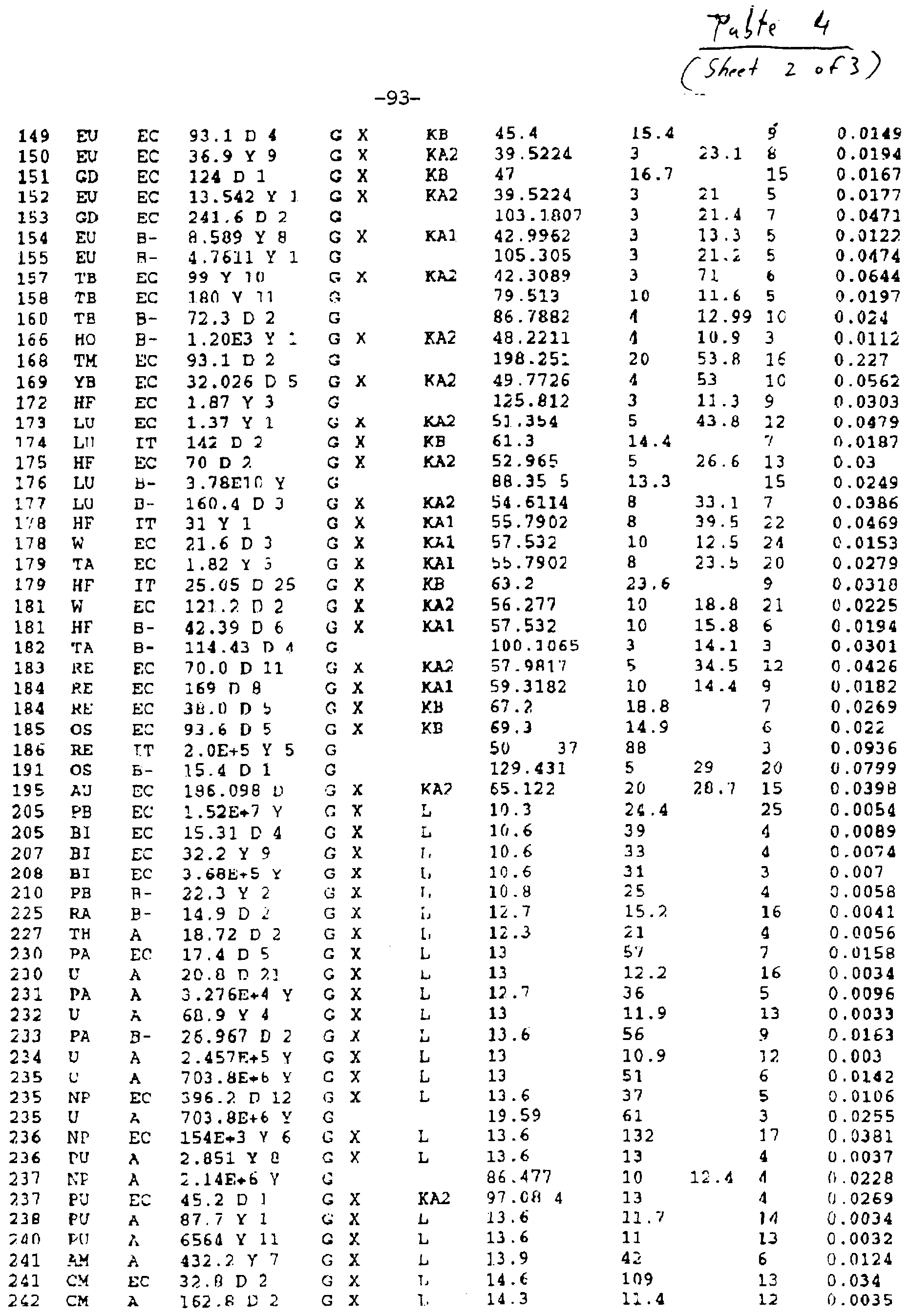

Claims
Priority Applications (4)
| Application Number | Priority Date | Filing Date | Title |
|---|---|---|---|
| JP9520701A JP2000501955A (en) | 1995-11-30 | 1996-11-27 | Apparatus and method for treating disease progression in a luminal structure |
| AU12757/97A AU722124B2 (en) | 1995-11-30 | 1996-11-27 | Apparatus and method to treat a disease process in a luminal structure |
| EP96943539A EP0874664A4 (en) | 1995-11-30 | 1996-11-27 | Apparatus and method to treat a disease process in a luminal structure |
| CA002238302A CA2238302A1 (en) | 1995-11-30 | 1996-11-27 | Apparatus and method to treat a disease process in a luminal structure |
Applications Claiming Priority (4)
| Application Number | Priority Date | Filing Date | Title |
|---|---|---|---|
| US08/565,093 US5707332A (en) | 1994-01-21 | 1995-11-30 | Apparatus and method to reduce restenosis after arterial intervention |
| US08/565,093 | 1995-11-30 | ||
| US08/717,232 US6217503B1 (en) | 1994-01-21 | 1996-09-26 | Apparatus and method to treat a disease process in a luminal structure |
| US08/717,232 | 1996-09-26 |
Publications (2)
| Publication Number | Publication Date |
|---|---|
| WO1997019723A1 true WO1997019723A1 (en) | 1997-06-05 |
| WO1997019723A9 WO1997019723A9 (en) | 1998-02-05 |
Family
ID=27073758
Family Applications (1)
| Application Number | Title | Priority Date | Filing Date |
|---|---|---|---|
| PCT/US1996/019084 WO1997019723A1 (en) | 1995-11-30 | 1996-11-27 | Apparatus and method to treat a disease process in a luminal structure |
Country Status (6)
| Country | Link |
|---|---|
| US (2) | US6217503B1 (en) |
| EP (1) | EP0874664A4 (en) |
| JP (1) | JP2000501955A (en) |
| AU (1) | AU722124B2 (en) |
| CA (1) | CA2238302A1 (en) |
| WO (1) | WO1997019723A1 (en) |
Cited By (20)
| Publication number | Priority date | Publication date | Assignee | Title |
|---|---|---|---|---|
| EP0963182A1 (en) * | 1996-09-26 | 1999-12-15 | The Trustees Of Columbia University In The City Of New York | Method of treating a disease process in a luminal structure |
| EP0998330A1 (en) * | 1997-07-24 | 2000-05-10 | Proxima Therapeutics, Inc. | Double-wall balloon catheter for treatment of proliferative tissue |
| WO2001043826A1 (en) | 1999-12-16 | 2001-06-21 | Proxima Therapeutics, Inc. | Asymmetric radiation dosing apparatus and method |
| SG91308A1 (en) * | 1998-05-04 | 2002-09-17 | Novoste Corp | Intraluminal radiation treatment system |
| US6673006B2 (en) | 2001-06-15 | 2004-01-06 | Proxima Therapeutics, Inc. | Tissue positioning apparatus and method for protecting tissue from radiotherapy |
| US6695760B1 (en) | 2002-10-11 | 2004-02-24 | Proxima Therapeutics | Treatment of spinal metastases |
| US6749555B1 (en) | 2003-02-13 | 2004-06-15 | Proxima Therapeutics, Inc. | System and method for the treatment of spinal metastases |
| US7354391B2 (en) | 2003-11-07 | 2008-04-08 | Cytyc Corporation | Implantable radiotherapy/brachytherapy radiation detecting apparatus and methods |
| US7494457B2 (en) | 2003-11-07 | 2009-02-24 | Cytyc Corporation | Brachytherapy apparatus and method for treating a target tissue through an external surface of the tissue |
| US7524274B2 (en) | 2003-11-07 | 2009-04-28 | Cytyc Corporation | Tissue positioning systems and methods for use with radiation therapy |
| US7524275B2 (en) | 2003-11-14 | 2009-04-28 | Cytyc Corporation | Drug eluting brachytherapy methods and apparatus |
| US7905822B2 (en) | 2003-11-20 | 2011-03-15 | Cytyc Corporation | Brachytherapy method and applicator for treatment of metastatic lesions in a load bearing region |
| US8303477B2 (en) | 2007-08-24 | 2012-11-06 | Cytyc Corporation | Fluid radiation shield for brachytherapy |
| US8328711B2 (en) | 2007-12-18 | 2012-12-11 | Cytyc Corporation | Selectable multi-lumen brachytherapy devices and methods |
| US8382650B2 (en) | 2009-05-11 | 2013-02-26 | Cytyc Corporation | Catheter marking for multi-lumen catheter identification |
| US9180312B2 (en) | 2005-11-18 | 2015-11-10 | Hologic, Inc. | Brachytherapy device for asymmetrical irradiation of a body cavity |
| US9623260B2 (en) | 2004-11-05 | 2017-04-18 | Theragenics Corporation | Expandable brachytherapy device |
| US10022557B2 (en) | 2010-09-30 | 2018-07-17 | Hologic, Inc. | Using a guided member to facilitate brachytherapy device swap |
| US10207126B2 (en) | 2009-05-11 | 2019-02-19 | Cytyc Corporation | Lumen visualization and identification system for multi-lumen balloon catheter |
| US10342992B2 (en) | 2011-01-06 | 2019-07-09 | Hologic, Inc. | Orienting a brachytherapy applicator |
Families Citing this family (55)
| Publication number | Priority date | Publication date | Assignee | Title |
|---|---|---|---|---|
| DK0633041T3 (en) | 1993-07-01 | 2000-04-03 | Schneider Europ Gmbh | Medical apparatus for the treatment of blood vessels by means of ionizing radiation |
| EP0686342B1 (en) | 1994-06-10 | 1998-09-09 | Schneider (Europe) GmbH | A medical appliance for the treatment of a portion of body vessel by ionising radiation |
| US6234951B1 (en) | 1996-02-29 | 2001-05-22 | Scimed Life Systems, Inc. | Intravascular radiation delivery system |
| US6398709B1 (en) | 1999-10-19 | 2002-06-04 | Scimed Life Systems, Inc. | Elongated member for intravascular delivery of radiation |
| US6416457B1 (en) | 2000-03-09 | 2002-07-09 | Scimed Life Systems, Inc. | System and method for intravascular ionizing tandem radiation therapy |
| US6994688B2 (en) * | 2000-05-18 | 2006-02-07 | Theragenics Corporation | Catheter attachment and catheter for brachytherapy |
| US6471671B1 (en) | 2000-08-23 | 2002-10-29 | Scimed Life Systems, Inc. | Preloaded gas inflation device for balloon catheter |
| US7101391B2 (en) * | 2000-09-18 | 2006-09-05 | Inflow Dynamics Inc. | Primarily niobium stent |
| US7402173B2 (en) * | 2000-09-18 | 2008-07-22 | Boston Scientific Scimed, Inc. | Metal stent with surface layer of noble metal oxide and method of fabrication |
| US6416492B1 (en) | 2000-09-28 | 2002-07-09 | Scimed Life Systems, Inc. | Radiation delivery system utilizing intravascular ultrasound |
| US6540720B1 (en) | 2000-11-10 | 2003-04-01 | Scimed Life Systems, Inc. | Miniature x-ray unit |
| US6546080B1 (en) * | 2000-11-10 | 2003-04-08 | Scimed Life Systems, Inc. | Heat sink for miniature x-ray unit |
| US6551278B1 (en) * | 2000-11-10 | 2003-04-22 | Scimed Life Systems, Inc. | Miniature x-ray catheter with retractable needles or suction means for positioning at a desired site |
| US6554757B1 (en) | 2000-11-10 | 2003-04-29 | Scimed Life Systems, Inc. | Multi-source x-ray catheter |
| US6540655B1 (en) | 2000-11-10 | 2003-04-01 | Scimed Life Systems, Inc. | Miniature x-ray unit |
| US6540733B2 (en) * | 2000-12-29 | 2003-04-01 | Corazon Technologies, Inc. | Proton generating catheters and methods for their use in enhancing fluid flow through a vascular site occupied by a calcified vascular occlusion |
| WO2003000314A2 (en) | 2001-06-20 | 2003-01-03 | The Regents Of The University Of California | Hemodialysis system and method |
| US7070554B2 (en) * | 2003-01-15 | 2006-07-04 | Theragenics Corporation | Brachytherapy devices and methods of using them |
| US20050143965A1 (en) * | 2003-03-14 | 2005-06-30 | Failla Gregory A. | Deterministic computation of radiation doses delivered to tissues and organs of a living organism |
| US20060162740A1 (en) * | 2005-01-21 | 2006-07-27 | Cerionx, Inc. | Method and apparatus for cleaning and surface conditioning objects using non-equilibrium atmospheric pressure plasma |
| US20060020157A1 (en) * | 2004-07-26 | 2006-01-26 | Stillwagon Gary B | Internal radiation therapy for low lying lesions |
| US7093476B2 (en) * | 2004-09-15 | 2006-08-22 | Ut-Battelle, Llc | Method for fabricating thin californium-containing radioactive source wires |
| US8080057B2 (en) * | 2005-08-09 | 2011-12-20 | Steven J. Kronowitz | Methods and devices for breast reconstruction |
| US20070270627A1 (en) * | 2005-12-16 | 2007-11-22 | North American Scientific | Brachytherapy apparatus for asymmetrical body cavities |
| US8137256B2 (en) * | 2005-12-16 | 2012-03-20 | Portola Medical, Inc. | Brachytherapy apparatus |
| US7993303B2 (en) | 2006-04-21 | 2011-08-09 | Abbott Laboratories | Stiffening support catheter and methods for using the same |
| US7927305B2 (en) * | 2006-04-21 | 2011-04-19 | Abbott Laboratories | Systems, methods, and devices for injecting media contrast |
| US20070250149A1 (en) * | 2006-04-21 | 2007-10-25 | Abbott Laboratories | Stiffening Support Catheters and Methods for Using the Same |
| US20080065014A1 (en) * | 2006-04-21 | 2008-03-13 | Abbott Laboratories | Systems, Methods, and Devices to Facilitate Wire and Device Crossings of Obstructions in Body Lumens |
| US8206370B2 (en) * | 2006-04-21 | 2012-06-26 | Abbott Laboratories | Dual lumen guidewire support catheter |
| US8246574B2 (en) * | 2006-04-21 | 2012-08-21 | Abbott Laboratories | Support catheter |
| WO2008058089A2 (en) * | 2006-11-03 | 2008-05-15 | North American Scientific, Inc. | Brachytherapy device having seed tubes with individually-settable tissue spacings |
| US7771340B2 (en) * | 2007-07-28 | 2010-08-10 | Xoft, Inc. | Method and apparatus for modifying distance from a brachytherapy radiation source to sensitive anatomical structures |
| US8603029B2 (en) | 2007-10-10 | 2013-12-10 | Hospi Corporation | Apparatuses and methods for medication administration |
| US9592408B2 (en) * | 2008-04-24 | 2017-03-14 | Koninklijke Philips N.V. | Dose-volume kernel generation |
| US8932340B2 (en) | 2008-05-29 | 2015-01-13 | Boston Scientific Scimed, Inc. | Bifurcated stent and delivery system |
| WO2010022108A2 (en) * | 2008-08-18 | 2010-02-25 | Envisionier Medical Technologies, Inc. | Fluid delivery catheter apparatus |
| US20110201996A1 (en) * | 2008-08-27 | 2011-08-18 | Melder Patrick C | Nasal ventilation system and method of using same |
| US8945142B2 (en) | 2008-08-27 | 2015-02-03 | Cook Medical Technologies Llc | Delivery system for implanting nasal ventilation tube |
| WO2013116670A1 (en) | 2012-02-01 | 2013-08-08 | Hospi Corporation | Valved enteral administration assembly |
| US9579524B2 (en) | 2009-02-11 | 2017-02-28 | Hologic, Inc. | Flexible multi-lumen brachytherapy device |
| US9248311B2 (en) | 2009-02-11 | 2016-02-02 | Hologic, Inc. | System and method for modifying a flexibility of a brachythereapy catheter |
| KR102015262B1 (en) * | 2011-07-25 | 2019-10-21 | 아클라런트, 인코포레이션 | Devices and methods for transnasal dilation and irrigation of the sinuses |
| MX2014001145A (en) * | 2011-07-28 | 2014-02-27 | Acclarent Inc | Improved device and method for dilating an airway stenosis. |
| US9358042B2 (en) | 2013-03-13 | 2016-06-07 | The Spectranetics Corporation | Expandable member for perforation occlusion |
| US9956384B2 (en) | 2014-01-24 | 2018-05-01 | Cook Medical Technologies Llc | Articulating balloon catheter and method for using the same |
| KR101665615B1 (en) * | 2015-04-20 | 2016-10-12 | 국립암센터 | Apparatus for in-vivo dosimetry in radiotherapy |
| US10499892B2 (en) | 2015-08-11 | 2019-12-10 | The Spectranetics Corporation | Temporary occlusion balloon devices and methods for preventing blood flow through a vascular perforation |
| US10449336B2 (en) | 2015-08-11 | 2019-10-22 | The Spectranetics Corporation | Temporary occlusions balloon devices and methods for preventing blood flow through a vascular perforation |
| US10478133B2 (en) * | 2016-10-20 | 2019-11-19 | General Electric Company | Systems and methods for calibrating a nuclear medicine imaging system |
| US10350395B2 (en) | 2017-06-23 | 2019-07-16 | Cook Medical Technologies Llc | Introducer for lumen support or dilation |
| US11794034B1 (en) * | 2018-04-13 | 2023-10-24 | Carilion Clinic | Infusion devices and methods of using them |
| US11628282B2 (en) | 2019-11-25 | 2023-04-18 | Neuravi Limited | No preparation balloon guide catheter |
| CN112587808B (en) * | 2020-12-08 | 2022-03-01 | 北京航空航天大学 | Particle stent dose distribution calculation method |
| WO2023154658A1 (en) * | 2022-02-11 | 2023-08-17 | Qsa Global Inc. | Hafnium-based gamma radiography sources, gamma radiation exposure devices, and methods of gamma radiography |
Citations (2)
| Publication number | Priority date | Publication date | Assignee | Title |
|---|---|---|---|---|
| US5106360A (en) * | 1987-09-17 | 1992-04-21 | Olympus Optical Co., Ltd. | Thermotherapeutic apparatus |
| US5411466A (en) * | 1991-09-05 | 1995-05-02 | Robert L. Hess | Apparatus for restenosis treatment |
Family Cites Families (27)
| Publication number | Priority date | Publication date | Assignee | Title |
|---|---|---|---|---|
| DE1065989B (en) | 1955-04-01 | 1959-09-24 | Willy Rüsch K. G., Rommelshausen über Waiblingen | DEVICE FOR RADIOACTIVE RADIATION OF COVER INTERIORS |
| US3173418A (en) * | 1961-01-10 | 1965-03-16 | Ostap E Baran | Double-wall endotracheal cuff |
| US3324847A (en) | 1964-06-01 | 1967-06-13 | Elias G Zoumboulis | Radioactive catheter |
| US3811426A (en) | 1973-05-21 | 1974-05-21 | Atomic Energy Commission | Method and apparatus for the in-vessel radiation treatment of blood |
| US3927325A (en) | 1974-07-10 | 1975-12-16 | Us Energy | Tissue irradiator |
| DE3442762A1 (en) | 1984-11-23 | 1986-06-26 | Anwer Dipl.-Ing. 8520 Erlangen Puthawala | REMOTE CONTROLLED AFTERLOADING DEVICE FOR BRACHYCURIE THERAPY OF TUMORS |
| WO1987004935A1 (en) | 1986-02-24 | 1987-08-27 | Fischell Robert | An intravascular stent and percutaneous insertion system |
| US4770653A (en) | 1987-06-25 | 1988-09-13 | Medilase, Inc. | Laser angioplasty |
| US5059166A (en) * | 1989-12-11 | 1991-10-22 | Medical Innovative Technologies R & D Limited Partnership | Intra-arterial stent with the capability to inhibit intimal hyperplasia |
| US5176617A (en) | 1989-12-11 | 1993-01-05 | Medical Innovative Technologies R & D Limited Partnership | Use of a stent with the capability to inhibit malignant growth in a vessel such as a biliary duct |
| US5199939B1 (en) | 1990-02-23 | 1998-08-18 | Michael D Dake | Radioactive catheter |
| US5059177A (en) | 1990-04-19 | 1991-10-22 | Cordis Corporation | Triple lumen balloon catheter |
| DE4018525C2 (en) | 1990-06-09 | 1994-05-05 | Kaltenbach Martin | Expandable area catheter |
| US5213561A (en) | 1990-09-06 | 1993-05-25 | Weinstein Joseph S | Method and devices for preventing restenosis after angioplasty |
| US5484384A (en) * | 1991-01-29 | 1996-01-16 | Med Institute, Inc. | Minimally invasive medical device for providing a radiation treatment |
| DE9102312U1 (en) | 1991-02-27 | 1992-06-25 | Weikl, Andreas, Dr.Med. | |
| US5429582A (en) * | 1991-06-14 | 1995-07-04 | Williams; Jeffery A. | Tumor treatment |
| WO1993004735A1 (en) | 1991-09-05 | 1993-03-18 | Cedars-Sinai Medical Center | Method and apparatus for restenosis treatment |
| JPH09501326A (en) | 1993-05-04 | 1997-02-10 | オムニトロン インターナショナル インコーポレイテッド | Radiation source wire, device using the same, and treatment method |
| DE4315002C1 (en) | 1993-05-06 | 1994-08-18 | Kernforschungsz Karlsruhe | Vascular implant |
| US5336184A (en) | 1993-07-15 | 1994-08-09 | Teirstein Paul S | Rapid exchange catheter |
| US5472425A (en) | 1993-07-15 | 1995-12-05 | Teirstein; Paul S. | Rapid exchange catheter |
| US5540659A (en) | 1993-07-15 | 1996-07-30 | Teirstein; Paul S. | Irradiation catheter and method of use |
| US6045495A (en) * | 1994-01-21 | 2000-04-04 | The Trustees Fo Columbia University In The City Of New York | Apparatus and method to treat a disease process in a luminal structure |
| US5503613A (en) * | 1994-01-21 | 1996-04-02 | The Trustees Of Columbia University In The City Of New York | Apparatus and method to reduce restenosis after arterial intervention |
| US5616114A (en) * | 1994-12-08 | 1997-04-01 | Neocardia, Llc. | Intravascular radiotherapy employing a liquid-suspended source |
| US5947889A (en) | 1995-01-17 | 1999-09-07 | Hehrlein; Christoph | Balloon catheter used to prevent re-stenosis after angioplasty and process for producing a balloon catheter |
-
1996
- 1996-09-26 US US08/717,232 patent/US6217503B1/en not_active Expired - Fee Related
- 1996-11-27 JP JP9520701A patent/JP2000501955A/en active Pending
- 1996-11-27 EP EP96943539A patent/EP0874664A4/en not_active Withdrawn
- 1996-11-27 CA CA002238302A patent/CA2238302A1/en not_active Abandoned
- 1996-11-27 AU AU12757/97A patent/AU722124B2/en not_active Ceased
- 1996-11-27 WO PCT/US1996/019084 patent/WO1997019723A1/en not_active Application Discontinuation
-
2001
- 2001-04-17 US US09/837,440 patent/US6652441B2/en not_active Expired - Fee Related
Patent Citations (2)
| Publication number | Priority date | Publication date | Assignee | Title |
|---|---|---|---|---|
| US5106360A (en) * | 1987-09-17 | 1992-04-21 | Olympus Optical Co., Ltd. | Thermotherapeutic apparatus |
| US5411466A (en) * | 1991-09-05 | 1995-05-02 | Robert L. Hess | Apparatus for restenosis treatment |
Cited By (30)
| Publication number | Priority date | Publication date | Assignee | Title |
|---|---|---|---|---|
| EP0963182A4 (en) * | 1996-09-26 | 2000-10-18 | Univ Columbia | Method of treating a disease process in a luminal structure |
| US6306073B1 (en) | 1996-09-26 | 2001-10-23 | The Trustees Of Columbia University In The City Of New York | Apparatus and method for treating a disease process in a luminal structure with a radionuclide and chelating agent |
| EP0963182A1 (en) * | 1996-09-26 | 1999-12-15 | The Trustees Of Columbia University In The City Of New York | Method of treating a disease process in a luminal structure |
| EP0998330A4 (en) * | 1997-07-24 | 2006-11-15 | Cytyc Corp | Double-wall balloon catheter for treatment of proliferative tissue |
| EP0998330A1 (en) * | 1997-07-24 | 2000-05-10 | Proxima Therapeutics, Inc. | Double-wall balloon catheter for treatment of proliferative tissue |
| US6413204B1 (en) | 1997-07-24 | 2002-07-02 | Proxima Therapeutics, Inc. | Interstitial brachytherapy apparatus and method for treatment of proliferative tissue diseases |
| US6482142B1 (en) | 1997-07-24 | 2002-11-19 | Proxima Therapeutics, Inc. | Asymmetric radiation dosing apparatus and method |
| SG91308A1 (en) * | 1998-05-04 | 2002-09-17 | Novoste Corp | Intraluminal radiation treatment system |
| WO2001043826A1 (en) | 1999-12-16 | 2001-06-21 | Proxima Therapeutics, Inc. | Asymmetric radiation dosing apparatus and method |
| US6673006B2 (en) | 2001-06-15 | 2004-01-06 | Proxima Therapeutics, Inc. | Tissue positioning apparatus and method for protecting tissue from radiotherapy |
| US7494456B2 (en) | 2001-06-15 | 2009-02-24 | Cytyc Corporation | Tissue positioning systems and methods for use with radiation therapy |
| US7381178B2 (en) | 2002-10-11 | 2008-06-03 | Cytyc Corporation | Treatment of spinal metastases |
| US6976949B2 (en) | 2002-10-11 | 2005-12-20 | Proxima Therapeutics, Inc. | Treatment of spinal metastases |
| US6695760B1 (en) | 2002-10-11 | 2004-02-24 | Proxima Therapeutics | Treatment of spinal metastases |
| US6749555B1 (en) | 2003-02-13 | 2004-06-15 | Proxima Therapeutics, Inc. | System and method for the treatment of spinal metastases |
| US7354391B2 (en) | 2003-11-07 | 2008-04-08 | Cytyc Corporation | Implantable radiotherapy/brachytherapy radiation detecting apparatus and methods |
| US7494457B2 (en) | 2003-11-07 | 2009-02-24 | Cytyc Corporation | Brachytherapy apparatus and method for treating a target tissue through an external surface of the tissue |
| US7524274B2 (en) | 2003-11-07 | 2009-04-28 | Cytyc Corporation | Tissue positioning systems and methods for use with radiation therapy |
| US7524275B2 (en) | 2003-11-14 | 2009-04-28 | Cytyc Corporation | Drug eluting brachytherapy methods and apparatus |
| US7905822B2 (en) | 2003-11-20 | 2011-03-15 | Cytyc Corporation | Brachytherapy method and applicator for treatment of metastatic lesions in a load bearing region |
| US9623260B2 (en) | 2004-11-05 | 2017-04-18 | Theragenics Corporation | Expandable brachytherapy device |
| US9415239B2 (en) | 2005-11-18 | 2016-08-16 | Hologic, Inc. | Brachytherapy device for facilitating asymmetrical irradiation of a body cavity |
| US9180312B2 (en) | 2005-11-18 | 2015-11-10 | Hologic, Inc. | Brachytherapy device for asymmetrical irradiation of a body cavity |
| US10413750B2 (en) | 2005-11-18 | 2019-09-17 | Hologic, Inc. | Brachytherapy device for facilitating asymmetrical irradiation of a body cavity |
| US8303477B2 (en) | 2007-08-24 | 2012-11-06 | Cytyc Corporation | Fluid radiation shield for brachytherapy |
| US8328711B2 (en) | 2007-12-18 | 2012-12-11 | Cytyc Corporation | Selectable multi-lumen brachytherapy devices and methods |
| US8382650B2 (en) | 2009-05-11 | 2013-02-26 | Cytyc Corporation | Catheter marking for multi-lumen catheter identification |
| US10207126B2 (en) | 2009-05-11 | 2019-02-19 | Cytyc Corporation | Lumen visualization and identification system for multi-lumen balloon catheter |
| US10022557B2 (en) | 2010-09-30 | 2018-07-17 | Hologic, Inc. | Using a guided member to facilitate brachytherapy device swap |
| US10342992B2 (en) | 2011-01-06 | 2019-07-09 | Hologic, Inc. | Orienting a brachytherapy applicator |
Also Published As
| Publication number | Publication date |
|---|---|
| US6652441B2 (en) | 2003-11-25 |
| US6217503B1 (en) | 2001-04-17 |
| JP2000501955A (en) | 2000-02-22 |
| CA2238302A1 (en) | 1997-06-05 |
| AU1275797A (en) | 1997-06-19 |
| EP0874664A4 (en) | 2006-08-23 |
| EP0874664A1 (en) | 1998-11-04 |
| US20010037046A1 (en) | 2001-11-01 |
| AU722124B2 (en) | 2000-07-20 |
Similar Documents
| Publication | Publication Date | Title |
|---|---|---|
| AU722124B2 (en) | Apparatus and method to treat a disease process in a luminal structure | |
| US5707332A (en) | Apparatus and method to reduce restenosis after arterial intervention | |
| WO1997019723A9 (en) | Apparatus and method to treat a disease process in a luminal structure | |
| US6306073B1 (en) | Apparatus and method for treating a disease process in a luminal structure with a radionuclide and chelating agent | |
| US6200256B1 (en) | Apparatus and method to treat a disease process in a luminal structure | |
| Nath et al. | Intravascular brachytherapy physics: report of the AAPM Radiation Therapy Committee Task Group no. 60 | |
| US7011619B1 (en) | Apparatus and methods for radiotherapy | |
| KR100228188B1 (en) | A radioactive stent and process for preparation thereof | |
| US6187037B1 (en) | Metal stent containing radioactivatable isotope and method of making same | |
| US6045495A (en) | Apparatus and method to treat a disease process in a luminal structure | |
| US20030166990A1 (en) | Radiation delivery catheters and dosimetry methods | |
| KR100228187B1 (en) | A radioactive ballon used in balloon dilatation catherer and process for preparation thereof | |
| JPH11505435A (en) | Balloon catheter for preventing restenosis of blood vessels after angioplasty and method for constructing the balloon catheter | |
| JP2002503530A (en) | Thin film irradiation source | |
| Amols | Review of endovascular brachytherapy physics for prevention of restenosis | |
| Jani | Gamma vs beta irradiation: Which is superior? | |
| Zamora et al. | Radiolabeling brachytherapy sources with re‐188 through chelating microfilms: Stents | |
| Yue et al. | Dosimetry calculation for a novel PHOSPHORUS-32-impregnated balloon angioplasty catheter for intravascular brachytherapy | |
| Nag et al. | Brachytherapy for the interventional cardiologist and vascular surgeon | |
| MXPA99002800A (en) | Method of treating a disease process in a luminal structure | |
| Amols | Methods to improve dose uniformity for radioactive stents in endovascular brachytherapy | |
| Waksman | Management of restenosis through radiation therapy | |
| Amols | Intravascular brachytherapy physics: introduction | |
| Mourtada | Brachytherapy, Intravascular |
Legal Events
| Date | Code | Title | Description |
|---|---|---|---|
| AK | Designated states |
Kind code of ref document: A1 Designated state(s): AU CA JP MX US US |
|
| AL | Designated countries for regional patents |
Kind code of ref document: A1 Designated state(s): AT BE CH DE DK ES FI FR GB GR IE IT LU MC NL PT SE |
|
| 121 | Ep: the epo has been informed by wipo that ep was designated in this application | ||
| DFPE | Request for preliminary examination filed prior to expiration of 19th month from priority date (pct application filed before 20040101) | ||
| COP | Corrected version of pamphlet |
Free format text: PAGES 1/26-26/26, DRAWINGS, REPLACED BY NEW PAGES BEARING THE SAME NUMBER; DUE TO LATE TRANSMITTAL BY THE RECEIVING OFFICE |
|
| WWE | Wipo information: entry into national phase |
Ref document number: PA/A/1998/003974 Country of ref document: MX |
|
| ENP | Entry into the national phase |
Ref document number: 2238302 Country of ref document: CA Ref document number: 2238302 Country of ref document: CA Kind code of ref document: A |
|
| ENP | Entry into the national phase |
Ref document number: 1997 520701 Country of ref document: JP Kind code of ref document: A |
|
| WWE | Wipo information: entry into national phase |
Ref document number: 1996943539 Country of ref document: EP |
|
| WWP | Wipo information: published in national office |
Ref document number: 1996943539 Country of ref document: EP |
|
| WWW | Wipo information: withdrawn in national office |
Ref document number: 1996943539 Country of ref document: EP |