US9814539B2 - Methods and apparatus for conformable prosthetic implants - Google Patents
Methods and apparatus for conformable prosthetic implants Download PDFInfo
- Publication number
- US9814539B2 US9814539B2 US11/075,840 US7584005A US9814539B2 US 9814539 B2 US9814539 B2 US 9814539B2 US 7584005 A US7584005 A US 7584005A US 9814539 B2 US9814539 B2 US 9814539B2
- Authority
- US
- United States
- Prior art keywords
- bone
- fixation
- implant
- implant body
- projection structure
- Prior art date
- Legal status (The legal status is an assumption and is not a legal conclusion. Google has not performed a legal analysis and makes no representation as to the accuracy of the status listed.)
- Expired - Fee Related, expires
Links
Images


Classifications
-
- A—HUMAN NECESSITIES
- A61—MEDICAL OR VETERINARY SCIENCE; HYGIENE
- A61B—DIAGNOSIS; SURGERY; IDENTIFICATION
- A61B90/00—Instruments, implements or accessories specially adapted for surgery or diagnosis and not covered by any of the groups A61B1/00 - A61B50/00, e.g. for luxation treatment or for protecting wound edges
- A61B90/10—Instruments, implements or accessories specially adapted for surgery or diagnosis and not covered by any of the groups A61B1/00 - A61B50/00, e.g. for luxation treatment or for protecting wound edges for stereotaxic surgery, e.g. frame-based stereotaxis
-
- A—HUMAN NECESSITIES
- A61—MEDICAL OR VETERINARY SCIENCE; HYGIENE
- A61B—DIAGNOSIS; SURGERY; IDENTIFICATION
- A61B17/00—Surgical instruments, devices or methods, e.g. tourniquets
- A61B17/16—Bone cutting, breaking or removal means other than saws, e.g. Osteoclasts; Drills or chisels for bones; Trepans
- A61B17/17—Guides or aligning means for drills, mills, pins or wires
- A61B17/1739—Guides or aligning means for drills, mills, pins or wires specially adapted for particular parts of the body
- A61B17/1757—Guides or aligning means for drills, mills, pins or wires specially adapted for particular parts of the body for the spine
-
- A—HUMAN NECESSITIES
- A61—MEDICAL OR VETERINARY SCIENCE; HYGIENE
- A61B—DIAGNOSIS; SURGERY; IDENTIFICATION
- A61B17/00—Surgical instruments, devices or methods, e.g. tourniquets
- A61B17/16—Bone cutting, breaking or removal means other than saws, e.g. Osteoclasts; Drills or chisels for bones; Trepans
- A61B17/17—Guides or aligning means for drills, mills, pins or wires
- A61B17/1739—Guides or aligning means for drills, mills, pins or wires specially adapted for particular parts of the body
- A61B17/1764—Guides or aligning means for drills, mills, pins or wires specially adapted for particular parts of the body for the knee
-
- A—HUMAN NECESSITIES
- A61—MEDICAL OR VETERINARY SCIENCE; HYGIENE
- A61F—FILTERS IMPLANTABLE INTO BLOOD VESSELS; PROSTHESES; DEVICES PROVIDING PATENCY TO, OR PREVENTING COLLAPSING OF, TUBULAR STRUCTURES OF THE BODY, e.g. STENTS; ORTHOPAEDIC, NURSING OR CONTRACEPTIVE DEVICES; FOMENTATION; TREATMENT OR PROTECTION OF EYES OR EARS; BANDAGES, DRESSINGS OR ABSORBENT PADS; FIRST-AID KITS
- A61F2/00—Filters implantable into blood vessels; Prostheses, i.e. artificial substitutes or replacements for parts of the body; Appliances for connecting them with the body; Devices providing patency to, or preventing collapsing of, tubular structures of the body, e.g. stents
- A61F2/02—Prostheses implantable into the body
- A61F2/30—Joints
- A61F2/38—Joints for elbows or knees
- A61F2/3859—Femoral components
-
- A—HUMAN NECESSITIES
- A61—MEDICAL OR VETERINARY SCIENCE; HYGIENE
- A61B—DIAGNOSIS; SURGERY; IDENTIFICATION
- A61B17/00—Surgical instruments, devices or methods, e.g. tourniquets
- A61B17/16—Bone cutting, breaking or removal means other than saws, e.g. Osteoclasts; Drills or chisels for bones; Trepans
- A61B17/1662—Bone cutting, breaking or removal means other than saws, e.g. Osteoclasts; Drills or chisels for bones; Trepans for particular parts of the body
- A61B17/1671—Bone cutting, breaking or removal means other than saws, e.g. Osteoclasts; Drills or chisels for bones; Trepans for particular parts of the body for the spine
-
- A—HUMAN NECESSITIES
- A61—MEDICAL OR VETERINARY SCIENCE; HYGIENE
- A61B—DIAGNOSIS; SURGERY; IDENTIFICATION
- A61B17/00—Surgical instruments, devices or methods, e.g. tourniquets
- A61B17/16—Bone cutting, breaking or removal means other than saws, e.g. Osteoclasts; Drills or chisels for bones; Trepans
- A61B17/1662—Bone cutting, breaking or removal means other than saws, e.g. Osteoclasts; Drills or chisels for bones; Trepans for particular parts of the body
- A61B17/1675—Bone cutting, breaking or removal means other than saws, e.g. Osteoclasts; Drills or chisels for bones; Trepans for particular parts of the body for the knee
-
- A—HUMAN NECESSITIES
- A61—MEDICAL OR VETERINARY SCIENCE; HYGIENE
- A61B—DIAGNOSIS; SURGERY; IDENTIFICATION
- A61B17/00—Surgical instruments, devices or methods, e.g. tourniquets
- A61B17/16—Bone cutting, breaking or removal means other than saws, e.g. Osteoclasts; Drills or chisels for bones; Trepans
- A61B2017/1602—Mills
-
- A—HUMAN NECESSITIES
- A61—MEDICAL OR VETERINARY SCIENCE; HYGIENE
- A61F—FILTERS IMPLANTABLE INTO BLOOD VESSELS; PROSTHESES; DEVICES PROVIDING PATENCY TO, OR PREVENTING COLLAPSING OF, TUBULAR STRUCTURES OF THE BODY, e.g. STENTS; ORTHOPAEDIC, NURSING OR CONTRACEPTIVE DEVICES; FOMENTATION; TREATMENT OR PROTECTION OF EYES OR EARS; BANDAGES, DRESSINGS OR ABSORBENT PADS; FIRST-AID KITS
- A61F2/00—Filters implantable into blood vessels; Prostheses, i.e. artificial substitutes or replacements for parts of the body; Appliances for connecting them with the body; Devices providing patency to, or preventing collapsing of, tubular structures of the body, e.g. stents
- A61F2/02—Prostheses implantable into the body
- A61F2/30—Joints
- A61F2002/30001—Additional features of subject-matter classified in A61F2/28, A61F2/30 and subgroups thereof
- A61F2002/30621—Features concerning the anatomical functioning or articulation of the prosthetic joint
- A61F2002/30649—Ball-and-socket joints
-
- A—HUMAN NECESSITIES
- A61—MEDICAL OR VETERINARY SCIENCE; HYGIENE
- A61F—FILTERS IMPLANTABLE INTO BLOOD VESSELS; PROSTHESES; DEVICES PROVIDING PATENCY TO, OR PREVENTING COLLAPSING OF, TUBULAR STRUCTURES OF THE BODY, e.g. STENTS; ORTHOPAEDIC, NURSING OR CONTRACEPTIVE DEVICES; FOMENTATION; TREATMENT OR PROTECTION OF EYES OR EARS; BANDAGES, DRESSINGS OR ABSORBENT PADS; FIRST-AID KITS
- A61F2/00—Filters implantable into blood vessels; Prostheses, i.e. artificial substitutes or replacements for parts of the body; Appliances for connecting them with the body; Devices providing patency to, or preventing collapsing of, tubular structures of the body, e.g. stents
- A61F2/02—Prostheses implantable into the body
- A61F2/30—Joints
- A61F2/38—Joints for elbows or knees
- A61F2002/3895—Joints for elbows or knees unicompartimental
-
- A—HUMAN NECESSITIES
- A61—MEDICAL OR VETERINARY SCIENCE; HYGIENE
- A61F—FILTERS IMPLANTABLE INTO BLOOD VESSELS; PROSTHESES; DEVICES PROVIDING PATENCY TO, OR PREVENTING COLLAPSING OF, TUBULAR STRUCTURES OF THE BODY, e.g. STENTS; ORTHOPAEDIC, NURSING OR CONTRACEPTIVE DEVICES; FOMENTATION; TREATMENT OR PROTECTION OF EYES OR EARS; BANDAGES, DRESSINGS OR ABSORBENT PADS; FIRST-AID KITS
- A61F2310/00—Prostheses classified in A61F2/28 or A61F2/30 - A61F2/44 being constructed from or coated with a particular material
- A61F2310/00005—The prosthesis being constructed from a particular material
- A61F2310/00011—Metals or alloys
Definitions
- This invention generally relates to methods and apparatus for prosthetic implant devices. More particularly, the present invention relates to prosthetic implants for joints that are conformable, preferably both at the time of implant and over the life of the implant.
- TKA Total knee arthroplasty
- U.S. Publ. Appl. 2003/0028196A1 and the PFC RP Knee Replacement manual provide a good background for the techniques and devices used as part of these arthroplasty procedures.
- the prosthetic implant devices for use in arthroplasty procedures are typically metallic devices or devices that have a combination of metallic and plastic components. Because of the high loads and strains that these devices must endure for years, almost invariably the design of these prosthetic implant devices relies on the rigid structure and durability of the metallic components to support the loads and strains. While the rigid structure and durability of metallic implants is beneficial in most regards, these features make the fit or interface between the metallic implant and the resected bone surface critical to the long term viability of an implant.
- a series of planar and/or curvilinear surfaces, or “resections,” are created to allow for the attachment of prosthetic or other devices to the femur, tibia and/or patella.
- resections planar and/or curvilinear surfaces, or “resections”
- the location and orientation of these resections are critical in that they dictate the final location and orientation of the distal femoral implant.
- U.S. Pat. Nos. 3,906,550 and 4,693,721 describe a porous metallic fabric for use as a medical implant.
- U.S. Pat. No. 5,986,169 describes a porous nickel-titanium metal alloy for use as a medical implant.
- European Publ. Appl. 0 761 242 A1 describes a molded polymer orthopedic implant with a bearing surface formed of a porous metal layer.
- PCT Publ. Appl. WO 02/34310 A2 describes a shape memory polymer material that is used as a connective tissue replacement material for orthopedic applications.
- the present invention is a biomechanical optimization (BMO) prosthetic implant that utilizes a thin cross-section of metallic material that is conformable.
- BMO prosthetic implant is conformable both at the time of implant in response to manipulation and fixation by the surgeon, as well as during the life of the implant in response to stresses and loads experienced by the implant and thereby communicated and responded to by living bone tissue.
- the BMO prosthetic implant will have an effective cross-sectional thickness of 3 mm or less.
- the BMO prosthetic implant is provided with one or more fins extending from the fixation surface(s) of the implant which preferably includes retaining structures, such as cross-pinned apertures or T-shaped edge ridge.
- the BMO Prosthetic implant is a composite of porous metal or ‘Trabecular Metal’ bone interface features joined to a thin layer of articular surface material such as cobalt chrome or titanium.
- This embodiment of the present invention is particularly advantageous as much of the literature available on both ActiporeTM (a porous nitinol, which forms a TiNi intermetallic molecule marketed by Biorthex, Inc.) and Trabecular Metal (chemical vapor deposition of tantalum on a porous carbon matrix manufactured by Implex, Inc. and distributed by Zimmer, Inc.) cites that the modulus of elasticity or stiffness of these materials is similar to that of living bone.
- the composite structure of the present invention creates an interfacial mechanical environment motivating a highly favorable biological response from the living bone while the articular surface of the present invention will providing for excellent articular function.
- this embodiment of the present invention may allow for the prosthesis, for example, a femoral or tibial component for use in knee replacement, to have a linear or curvilinear fixation profile of flexible porous material that is substantially thicker (at least 10% thicker, and in one preferred embodiment closer to 500% thicker) than the thickness of the composite articular surface, for intraoperative attachment to condylar cuts having a linear cutting profile of sufficient interfacial area to avoid subsidence of the implant into bone leading to failure.
- This embodiment can significantly improve the arthroplasty continuum of care for a given patient, as surgeons performing revision procedures will commonly remove necrotic tissue to a depth sufficient to reveal bleeding bone prior to implantation of the revision prostheses.
- porous metals are capable of accommodating healthy living bone within their interstices, this ensures that this embodiment of the present invention will require a minimum of bony material removal both intraoperatively during primary intervention and intraoperatively during revision intervention.
- Another alternate embodiment would further have the fin and/or keel and/or crosspin be constructed of such porous material.
- the present invention provides for embodiments of prosthetic implant designs facilitating intraoperative and postoperative efficacy and ease of use.
- the present invention utilizes a number of embodiments of prosthetic implants, or prosthetic implant features to facilitate clinical efficacy of arthroplasty procedures.
- the overriding objects of the embodiments are to facilitate short and long term fixation of the implant with respect to the bone, enable bone preservation to facilitate ease and efficacy of revision, and/or to take advantage of the natural physiological phenomenon determining bone growth response to load stimuli.
- science is beginning to understand the manner in which bone responds to mechanical stimuli to an extent that allows for at least first order prediction of the clinical performance of prosthetic implants attached to bone.
- Certain theories regarding bone response to prosthetic implant load transfer to bone are postulated herein and prosthetic implant design embodiments proposed to take advantage of these biomechanical characteristics in facilitating clinical performance are disclosed.
- FIGS. 1-42 show various depictions of embodiments and methods in accordance with alternate embodiments of the present invention.
- the cut surface created by the cutting tool are shown as having already been completed for the sake of clarity.
- the bones may be shown as being transparent or translucent for the sake of clarity.
- the guides/pins, cutting tool, bones, and other items disclosed are may be similarly represented for the sake of clarity or brevity.
- FIGS. 1 through 30 generally represent prosthesis and prosthesis fixation feature embodiments of the present invention.
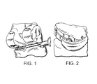
- FIGS. 2 through 5 show representations of a tongue in groove fixation feature applied to a Unicondylar femoral component enabling anterior insertion of one tongue element into a ‘t-slot’ style groove formed in bone and a progressively increasing press fit obtained by forcing the implant posteriorly, as is represented in comparing FIGS. 2 and 3 .
- the t-slot feature, or groove, formed in the femur is easily formed by, in one embodiment, providing a trial component possessing a contoured groove and slot for guiding a t-slot cutter along its length.
- Such a contour groove would be responsible for controlling the depth of the t-slot in the bone with respect to the cut surface to which the implant fixation surface is attached, while the slot in the trial would dictate the mediolateral location of the t-slot style groove. It is preferable to include an aperture in the slot and/or contour groove in the trial component to allow for insertion and plunging of the wider T cutting surfaces prior to sweeping.
- FIGS. 6 through 15 represent combinations of finned and/or crosspinned implants.
- the AP Fin Profile of the fin may be linear as shown in FIG. 9 (in other words, the fin may be may be planar), or it could be slightly tapered to achieve an interference fit with the walls of the groove as the implant fixation surfaces are forced into contact with the cut surfaces to which they are mated (see FIGS. 10 through 12 ), or in could be curved as looked at from the viewpoint of FIG. 9 to further provide stability of fixation.
- the fixation aperture created to fix a cutting guide to the bone could be utilized to cross pin a flange or fin of a femoral prosthesis.
- a tapered pin is used to engage the cross pin hole in the fin of the prosthesis.
- the tapered pin may be utilized to facilitate a resulting press fit between the pin and the fixation surfaces of the implant and/or ease of introducing the pin into the hole in the fin.
- the pin could be of any known material, but resorbable materials are especially interesting as they are ‘consumed’ by the body leaving minimal hardware within the body after a fairly predictable amount of time has passed.
- PLA/PGA compositions, Tricalcium Phosphate, allograft and autograft bone, bone substitutes, and the aforementioned slurry type compositions may serve well. Additionally, as the apertures shown in FIG.
- a very thin walled coring saw can be used to create the aperture and simultaneously form the crosspin that will be used to facilitate fixation of the implant.
- bone cement or other liquid or semi-liquid material may be injected into the portals/apertures to achieve intimate interdigitation, and the crosspins optionally inserted thereafter, but prior to complete hardening or curing.
- the crosspin(s) could be hollow with radially extending holes allowing the pins to be inserted and then have bone cement injected into them and up under the implant.
- the cross pin could be threaded to engage threads in the fin, or to engage the bone (both for short term stability and to facilitate removal) or both.
- the crosspin(s) could be formed of bone cement for use in cemented procedures.
- apertures may be present in the implant about more medial or lateral locations that allow the crosspins to mate with said apertures to create the aforementioned intimate fit or conformability in either or both of the ML and AP directions.
- the condylar sections, and patellofemoral sections of the implant could be wholely separate, modularly joined, be composed of a dual condylar prosthesis and separate patellofemoral prosthesis, or any combination of the above as generally indicated in FIGS. 23 through 30 .
- FIGS. 10 through 15 demonstrate another embodiment of the present invention allowing for benefits well above and beyond those of the prior art.
- This will be referred to herein as a BMO Prosthesis or BMO Cortical type implant (Biomechanical Optimization Prosthesis).
- This embodiment has several applications. For instance, if the resected surfaces will to vary significantly from the fixation surface geometries, as may be seen in unguided kinematic resection, it may be advantageous to implement fixation surface geometries that can conform to variation in resection geometry. Most implant materials in joint replacement are thought of as being rigid, and that their rigidity is a desirable characteristic for achieving stable fixation. In the case of surface replacement, that is not necessarily the case.
- the construct or prosthesis resulting from applying the present invention to a femoral component in Unicondylar knee replacement may start out being a 1′′ wide be 3′′ long strip of 1.5 mm thick material curved in a manner to generally look like the curved cutting path and curved cutting profile of a natural, healthy femur.
- a process such as Tecotex from Viasys Healthcare of Wilmington, Mass. is used to remove material from the strip down to a nominal thickness of perhaps 0.1 mm thick while leaving multiple protruding ‘hooks’ (almost like the hook and eye concept of Velcro) emerging from the thin fixation surface to engage the bone.
- One or more fins can be attached or be made a continuous part of this construct as shown in FIG. 10 .
- the anterior most cross pin could lock that portion of the prosthesis in place, then the prosthesis could be wrapped around the remaining, more posteriorly resected surfaces and the posterior cross pin inserted (see FIG. 14 ).
- the fins can be located about the periphery of the articular surfaces of the condyle in the form of tabs and the cross pins or screws or tapered dowels, etc. known in the art inserted through holes in the tabs and into bone to fix the cortical implant. The combination of fins and tabs may also be useful.
- the flexibility of the implant in accordance with the present invention allows the implant to conform to the resection surface and the stability of the crosspin fixation would assist in reducing interfacial micromotion known to inhibit bone ingrowth and fixation (this concept could be used with PMMA, but it is also desirable to avoid the tissue necrosis and bone preservation for revision issues associated with the use of bone cement if the patients health/comorbidities/indications allow).
- This kind of implant has some very interesting clinical benefits beyond simple bone preservation.
- BMO The concept of BMO depends on the concept that not only do human bones and articular surfaces in healthy patients seek uniform stresses in bearing, but that bone continues to seek this uniform state despite the pathologies of osteoarthritis. If an implant design is properly designed to allow for localized load transfer to underlying living bone, given that bone will seek an ideal, uniform stress state, it is believed that the bone will adapt its geometry and shape as per the loading it experiences and thus change the shape of the articular surfaces of the BMO implant to reflect ideal or uniform contact stress bearing between the implant articular surfaces.
- Another interesting embodiment of the present invention is to make both opposing implants BMO Cortical type implants and allow the bone to modify the geometry of both to reach an ideal ‘state’ for that patient (utilizing Liquid Metal as a metal on metal bearing in this scenario could yield phenomenal results not to mention unheard of bone preservation).
- the primary objectives of this embodiment of the present invention are to preserve viable bone, to increase prosthesis survival durations, to promote optimal joint kinematics, load transfer, articulation contact areas, and patient satisfaction, reduce intraoperative trauma and patient recovery time, reduce or eliminate proprioceptive compromise, reduce intraoperative time, and generally make the art of joint arthroplasty cheaper, better, and faster in all ways.
- BMO Cortical type prostheses would enable a given patient who, at younger than normal ages, experiences the debilitating or crippling effects of Osteoarthritis or Post-Traumatic arthritis to be able to be treated by arthroplasty over a period of decades, and a series of revisions that is simply not attainable today given the monolithic nature of conventional implants.
- bone morphogenic proteins bone graft, or other means of promoting or accelerating healing, fixation, and/or ingrowth of devices derived from this concept could be beneficial.
- application of these inventions to all joint arthroplasty procedures including TKA, hip, ankle, metatarsul, metacarpal, wrist, spine, elbow, shoulder, mandible, or finger or any other joint or bone or bone feature identified in Gray's Anatomy or effected in the aforementioned procedures is likely to provide significant clinical and economic benefit.
- Implantation of these devices could also be performed via standard surgical approaches or more exotic methods in the art including arthroscopic means or by what has been described as the Transosseous Core approach in the patent literature.
- the process of ‘packing’ the bone could be affected by simply reducing the joint and allowing the compression across the joint to pack the bone, by injection of osteoslurries into the interfacial area after placement of the implant, or by other currently known methods or those methods to be discovered.
- the work of Frost, et al and Lanyon, et al may also have identified several of the characteristics needed for successful replication of bone mechanics. Specifically, it has been identified that living bone tissue experiencing strain states between 50 microstrain to 4,000 microstrain achieves steady state growth balancing out consumption of bone by osteoclast activity and creation of new bone by osteoblast activities.
- FIGS. 31 through 37 concentrate on alignment guide and/or drill guide techniques.
- FIG. 31 shows a manually operated alignment guide suitable for use with surgical exposures (it should be noted that surgical navigation sensors could be used to assist in determining final drill guide location and orientation).
- FIGS. 32 and 33 show an improvement upon the embodiment shown in FIG. 31 for enabling manual alignment guide use in less invasive incisions by providing soft tissue accommodating contours or reliefs.
- the alignment guide is configured to allow for appropriate contact and referencing of the distal and posterior femoral condyles, the IM canal (when not relying on an extramedullary reference or inference of the mechanical axis) or IM Rod, the anterior cortex or anterior runout point of a given or proposed implant size (via a stylus not shown), and the epicondylar axis via palpitation or visual reference while the patellar tendon, patella, and/or quadriceps tendon is draped over the lateral side (right side as shown in the figures) of the alignment guide allowing insertion of the guide when the patella is neither everted not fully dislocated as in conventional techniques.
- initial alignment indicated by reference of the distal femur may be further adjusted in all six degrees of freedom as a fine tuning for final cut location and orientation.
- This simply calls for the inclusion of additional adjustment of the location and orientation of the crossbar mechanism and/or rotational alignment arm, with respect to the initial reference provide for by contact between the body of the guide and the bone (optionally including the IM Rod), in flexion-extension angulation, varus-valgus angulation (rotational angulation and Anterior-Posterior location are already shown), mediolateral location (represented in this embodiment of the current invention by the cross bar mechanism in FIG.
- drill guide mediolateral location is shown as being independently and infinitely adjustable
- proximal-distal location as shown in FIGS. 31, 32, and 33 —it should be noted that this adjustment might be best embodied in an infinitely adjustable slide as opposed to the incrementally adjustable slide shown, and that simple marking would be present indicating the relative movement of the slide with respect to the body). It may be desirable to only utilize only a medial drill guide plate with multiple drill guide bushings to create holes extending partially or completely across the femur depending upon the manner in which the guides are to be connected to the femur.
- FIGS. 34, 35, and 36 show an alternative alignment/drill guide embodiment of the present invention wherein a cannulated surgically navigated handle/drill guide is used to create fixation apertures in the bone for direct or indirect fixation of a cutting guide.
- a cannulated surgically navigated handle/drill guide is used to create fixation apertures in the bone for direct or indirect fixation of a cutting guide.
- FIG. 34 it may be advantageous to include tines for penetrating the bone to obtain initial stabilization of the handle in the location and orientation indicated by the surgical navigation system (“Surg Nav”—this term shall be used interchangeably with Computer Aided Surgical System or Image Guided Surgical System throughout this disclosure) prior to extending the drill, represented in FIG. 36 , into the bone to create the aperture.
- the surgical navigation system (“Surg Nav”—this term shall be used interchangeably with Computer Aided Surgical System or Image Guided Surgical System throughout this disclosure) prior to extending the drill, represented in FIG. 36 ,
- An alternate feature to the tines shown could be a smooth but thin walled cylindrical edge of sufficient thinness or sharpness allowing it to cut and penetrate the bone to achieve initial stabilization prior to drilling. It should be noted that the aperture, or hole, thus created could be blind or extended to a specific depth, or optionally extended entirely through the bone and out the furthest side of the bone. Importantly, this process could be utilized transcutaneously through a small stab wound (perhaps 4 mm in length) through the skin to the bone surface, or through a preformed incision through which other instrumentation of the present invention or other devices including the prosthetic implant may be introduced during a procedure.
- a single handle may desirably contain multiple cannulations, some or all of which could be adjustably extended into contact with the bone to reduce any wandering of the drill contacting oblique bone surfaces and improve the precision and accuracy of aperture creation (thus allowing for the creation of apertures in the medial side of the femur, represented in FIG. 37 , with a single Surg Nav Handle—Also, the apertures of the drill guide may be configured such that the femoral and tibial apertures shown in FIG. 37 are all created using a single positioning step for the handle). As represented in FIG.
- the navigation system (the computer and the sensors) may be capable of determining appropriate location and orientation to +/ ⁇ 0.5 mm and +/ ⁇ 0.5 degrees, but if the location and/orientation of the aperture created represents some path of least resistance in bone which is followed by the drill, the resultant location and orientation of cut surfaces, and thereby the location and orientation of the prosthesis attached thereto, will likely be seriously in error.
- the aperture creation step is not carefully controlled, you will have a very expensive alignment system whose stated purpose is to increase reproducibility, and whose method of implementation compromises this stated purpose.
- FIGS. 38A through 39 represent embodiments of the present invention for use in bone preserving resection techniques.
- a significant amount of viable bone tissue may be preserved while maintaining all functional paradigms of conventional TKA while improving articular conformity in the deepest ranges of flexion. It is of particular interest to note that this is especially applicable in improving the results of conventional Unicondylar implant performance, as the current state of the art makes minimal planar posterior cuts which prohibit articular conformity in deep flexion.
- FIGS. 17 through 19 are an embodiment of the present invention that may prove to be a very usefully alternative to conventional rectilinear based referencing techniques.
- conventional alignment techniques once having established appropriate flexion extension angulation and varus valgus angulation of desired implant location, reference the anterior cortex, distal most femoral condylar surface, and posterior most condylar surface (indicated in FIG.
- the embodiment of the present invention is an alternative alignment technique with an object to overcome the errors inherent in prior art. As shown in FIG.
- the femur possesses two distinct kinematic features and functions that lend themselves to physical referencing; the patellofemoral articular surface and the tibiofemoral articular surfaces, both of which are curved, more specifically these surfaces represent logarithmic curves.
- the one codependency between the two articular functions, and therefore any geometric approximation made of them in referencing, is that they must allow for smooth kinematically appropriate articulation of the patella as it passes from its articulation with the trochlear groove to its articulation with intercondylar surfaces between the femoral condyles.
- a referencing device which contacts at least one femoral condyle at three points to determine both an approximation of arc radius and centerpoint location, while independently or simultaneously referencing the trochlear groove at three points to determine both an approximation of arc radius and centerpoint location.
- the referencing system would further need to provide for the need of the articular surfaces of the trochlear articular surfaces to smoothly transition to those of the intercondylar surfaces.
- FIG. 26 represents one method of fixing the patellofemoral implant with respect to the condylar implant(s) so as to maintain smooth transitional articulation. It should be noted that this crosspin method of interconnecting the separate components could be augmented by tongue and groove interlocking between the medial side of the condylar component shown and the lateral side of the patellofemoral component shown. What is critical is that the transition between the patellofemoral component and the condylar component surfaces responsible for patellofemoral articulation are and remain tangent at least one point.
- Image guidance techniques typically involve acquiring preoperative images of the relevant anatomical structures and generating a data base which represents a three dimensional model of the anatomical structures.
- the relevant surgical instruments typically have a known and fixed geometry which is also defined preoperatively.
- the position of the instrument being used is registered with the anatomical coordinate system and a graphical display showing the relative positions of the tool and anatomical structure may be computed in real time and displayed for the surgeon to assist the surgeon in properly positioning and manipulating the surgical instrument with respect to the relevant anatomical structure.
- the relevant dimensional data concerning an anatomical structure of interest may be determined using data acquired from images of the anatomical structure to generate a data base representing a model of the anatomical structure.
- the model of the anatomical structure may be a three dimensional model which is developed by acquiring a series of two dimensional images of the anatomical structure.
- the model of the anatomical structure may be a set of two dimensional images having known spatial relationships or other data structure which can be used to convey information concerning the three dimensional form of the anatomical structure.
- the model of the anatomical structure may then be used to generate displays of the anatomical structure from various perspectives for preoperative planning purposes and intraoperative navigational purposes.
- a variety of technologies which may be employed to generate such a model of an anatomical structure are well known in the art and include computed tomography (CT), magnetic resonance imaging (MRI), positron emission tomography (PET), ultrasound scanning and fluoroscopic imaging technologies.
- the present invention contemplates a computer-based method of generating a surgical plan comprising reading digital data associated with a 3D (three-dimensional) model of a patient's bone, wherein the digital data resides in a memory in a computer; and generating a surgical plan for the patient's bone based on an analysis of the digital data associated with the 3D model.
- a surgical planner/simulator module in the computer assisted orthopedic surgery planner software makes a detailed surgical plan using realistic 3D computer graphics and animation.
- the simulated surgical plan may be viewed on a display seen of a personal computer.
- the planner module may also generate a pre-surgery report documenting various aspects of the bone surgery.
- FIGS. 40 through 42 An implant design embodying fixation geometries for mating with such tibial cut surfaces as are shown in FIGS. 40 through 42 is highly desirable.
- the fixation surfaces would be intended to mate, directly or indirectly, with cut surfaces represented in FIGS. 41 and/or 42 (the tibia in the right side of the FIG. 42 ).
- the tibial implant would possess a planar or gently curvilinear ‘rim’ for contacting the ‘cortical skim cut’ surface (represented in FIG. 40 ), and convex fixation surfaces for direct or indirect fixation to the concave tibial cuts represented in FIGS. 41 and 42 .
- Direct fixation to such surfaces could be achieved by high precision resection of both the cortical rim, for attachment of the rim of the tibial prosthesis, and the concave surface(s), for intimate apposition to the convex implant surfaces.
- Such fixation, specifically of the concave bone cuts to the convex implant surfaces could be achieved by way of an interference fit between the cuts and the implant along one axis (for instance, a front to back—AP—axis or direction), or along two axes (for instance, AP and Side to Side—ML—axes), or circumferentially (in other words a bit like a pin of a given diameter being forced into a hole of a lesser diameter), or both circumferentially and along an axis at roughly a 90 degree angle or normal to the skim cut surface when viewed in one or two orthogonal planes (an “up and down axis” or superior-inferior or proximal distal direction).
- an interference fit in a roughly superior-inferior direction may call for a textured surface on the bottom most surface of the convex fixation surfaces presenting a small surface area of contact at initial contact with the bottom of the concave cut to allow the implant to compact a reduced area of cancellous bone as the implant is impacted in a superior to inferior direction until it reaches its desired superior-inferior location and/or contact between the rim of the implant and the skim cut of the cortices.
- these embodiments of the present invention yield superior stability of implant fixation to bone to an extent pronounced of the difference between riding a horse wearing a deeply dished saddle and riding a very sweaty horse bareback.
- the concave surface may be ‘excavated’ in any desired manner (such as the Cutting Trials which cut the proximal tibia while the tibia is moved through at least a portion of its range of motion about the femur), and a morselized or granular osteobiological substance, perhaps tricalcium phosphate, HATCP, or other substances generally described as ‘bone substitutes’ or autograft or allograft cancellous or cortical bone (it would be very useful to use the bone which was removed from the tibia or other patient bone during the creation of the cut(s) in that it is readily available and completely avoids the issues of disease transmission or immune response), is then impacted into the concave surface using a ‘form’ to create a surface of impact material (referred to herein as the “Impacted Surface”) of specific shape and location/orientation with respect to the cor
- This form is beneficially shaped in a manner related to the shape of the convex implant fixation surface shape so as to create a specific geometric relationship between the implant fixation surfaces and the Impacted Surface geometry.
- the fit between the implant and the Impacted Surface would be an interference fit or press fit.
- the fit would leave a significant gap, perhaps 0.2 mm to 4.0 mm in width, between portions or all of the convex fixation surfaces of the implant and the convex cut(s), into which bone cement or other substance would then be injected or impacted achieving interdigitation with both the surfaces of the prosthesis and the material of the Impacted Surface.
- such a method prevents excessive micromotion or strain at the interface between the implant (and/or the composite interface) and living tissue during the postoperative healing process, which, in essence, gives the bone a chance to further stabilize its fixation to the implant by way of bone modeling or remodeling in response to load transfer.
- it is highly beneficial to maintain the strain state within living bone at and/or beneath and/or in the general vicinity of the bone implant interface within a range of 50 microstrain to 4000 microstrain so as to elicit the formation of bone tissue at and around the interface—strain levels in excess of 4000 microstrain or less than 50 microstrain are very likely to elicit the formation of fibrocartilagenous tissues at the interface which may lead to aseptic loosening of the implant.
- a small hole located at or beneath the skim cut allows for the injection of the material beneath the implant to achieve intimate and controlled interdigitation.
- the implant could be seated ‘over’ the freshly cut concave surfaces, and a slurry of biologically active and/or mechanically robust material(s) injected into the gaps between the implant and the bone under controlled pressure. Injection could be achieved via the portal shown in FIG. 42 .
- a slurry may comprise a mixture of substances such as morselized patient bone and bone cement, but alternative or additional materials including bone substitutes, osteobiologicals such as bone morphogenic proteins, antibiotics, or even living cells such as T cells known to promote post-operative healing and long term implant fixation.
- a fin feature may be added to these embodiments to facilitate additional mechanical stability, and said stem feature could beneficially possess an aperture for cross-pin fixation as described below for use in conjunction with the cross pins represented in FIG. 14 .
- the location and geometry of the concave tibial cut allows for the use of a bearing insert (conventionally made of materials such as polyethylene or other materials capable of ‘whetting’ or mimicking the benefits of ‘whetting’ during bearing contact; mimicking constituting, in one embodiment, the absence or mitigation of wear debris generation despite the application of significant bearing forces, in TKA in excess of 200 lbs and often as much as 500 lbs or more) whose ‘underside’ is convexly shaped to mate with a concavely shaped mating or accommodating surface in the upper surface of the tibial implant or ‘baseplate’ as it is sometimes referred to.
- tibial insert(s) whose thickness, in the areas beneath where the femoral implant bears against the tibial insert, may be equal to or greater than those insert thicknesses used in the past (those associated with predominantly planar tibial cuts) while require removal of significantly less structurally viable bone from the cortical rim of the proximal tibia than past efforts. Determination of the geometry and location of the baseplate's concave surface and therefore the areas of greatest insert or bearing surface are easily determined by analysis of the wear patterns of retrieved tibial inserts.
Abstract
Description
Claims (28)
Priority Applications (2)
| Application Number | Priority Date | Filing Date | Title |
|---|---|---|---|
| US11/075,840 US9814539B2 (en) | 2004-01-14 | 2005-03-08 | Methods and apparatus for conformable prosthetic implants |
| US15/810,726 US20180125602A1 (en) | 2004-01-14 | 2017-11-13 | Methods and apparatus for conformable prosthetic implants |
Applications Claiming Priority (12)
| Application Number | Priority Date | Filing Date | Title |
|---|---|---|---|
| US53632004P | 2004-01-14 | 2004-01-14 | |
| US54099204P | 2004-02-02 | 2004-02-02 | |
| US55130704P | 2004-03-08 | 2004-03-08 | |
| US55163104P | 2004-03-08 | 2004-03-08 | |
| US55116004P | 2004-03-08 | 2004-03-08 | |
| US55107804P | 2004-03-08 | 2004-03-08 | |
| US55108004P | 2004-03-08 | 2004-03-08 | |
| US55109604P | 2004-03-08 | 2004-03-08 | |
| US55126204P | 2004-03-08 | 2004-03-08 | |
| US11/036,584 US7815645B2 (en) | 2004-01-14 | 2005-01-14 | Methods and apparatus for pinplasty bone resection |
| US11/049,634 US20060030854A1 (en) | 2004-02-02 | 2005-02-02 | Methods and apparatus for wireplasty bone resection |
| US11/075,840 US9814539B2 (en) | 2004-01-14 | 2005-03-08 | Methods and apparatus for conformable prosthetic implants |
Related Parent Applications (3)
| Application Number | Title | Priority Date | Filing Date |
|---|---|---|---|
| US11/036,584 Continuation-In-Part US7815645B2 (en) | 2004-01-14 | 2005-01-14 | Methods and apparatus for pinplasty bone resection |
| US11/049,634 Continuation-In-Part US20060030854A1 (en) | 2004-01-14 | 2005-02-02 | Methods and apparatus for wireplasty bone resection |
| US11/075,840 Continuation-In-Part US9814539B2 (en) | 2004-01-14 | 2005-03-08 | Methods and apparatus for conformable prosthetic implants |
Related Child Applications (2)
| Application Number | Title | Priority Date | Filing Date |
|---|---|---|---|
| US11/075,840 Continuation-In-Part US9814539B2 (en) | 2004-01-14 | 2005-03-08 | Methods and apparatus for conformable prosthetic implants |
| US15/810,726 Continuation US20180125602A1 (en) | 2004-01-14 | 2017-11-13 | Methods and apparatus for conformable prosthetic implants |
Publications (3)
| Publication Number | Publication Date |
|---|---|
| US20060058882A1 US20060058882A1 (en) | 2006-03-16 |
| US20160302933A9 US20160302933A9 (en) | 2016-10-20 |
| US9814539B2 true US9814539B2 (en) | 2017-11-14 |
Family
ID=35717493
Family Applications (7)
| Application Number | Title | Priority Date | Filing Date |
|---|---|---|---|
| US11/075,836 Active 2029-07-24 US8287545B2 (en) | 2004-01-14 | 2005-03-08 | Methods and apparatus for enhanced retention of prosthetic implants |
| US11/074,599 Abandoned US20060015115A1 (en) | 2004-01-14 | 2005-03-08 | Methods and apparatus for pivotable guide surfaces for arthroplasty |
| US11/075,553 Abandoned US20060030855A1 (en) | 2004-02-02 | 2005-03-08 | Methods and apparatus for improved profile based resection |
| US11/075,840 Expired - Fee Related US9814539B2 (en) | 2004-01-14 | 2005-03-08 | Methods and apparatus for conformable prosthetic implants |
| US11/825,857 Expired - Fee Related US8353914B2 (en) | 2004-02-02 | 2007-07-09 | Methods and apparatus for improved profile based resection |
| US12/187,210 Expired - Fee Related US8298238B2 (en) | 2004-01-14 | 2008-08-06 | Methods and apparatus for pivotable guide surfaces for arthroplasty |
| US15/810,726 Abandoned US20180125602A1 (en) | 2004-01-14 | 2017-11-13 | Methods and apparatus for conformable prosthetic implants |
Family Applications Before (3)
| Application Number | Title | Priority Date | Filing Date |
|---|---|---|---|
| US11/075,836 Active 2029-07-24 US8287545B2 (en) | 2004-01-14 | 2005-03-08 | Methods and apparatus for enhanced retention of prosthetic implants |
| US11/074,599 Abandoned US20060015115A1 (en) | 2004-01-14 | 2005-03-08 | Methods and apparatus for pivotable guide surfaces for arthroplasty |
| US11/075,553 Abandoned US20060030855A1 (en) | 2004-02-02 | 2005-03-08 | Methods and apparatus for improved profile based resection |
Family Applications After (3)
| Application Number | Title | Priority Date | Filing Date |
|---|---|---|---|
| US11/825,857 Expired - Fee Related US8353914B2 (en) | 2004-02-02 | 2007-07-09 | Methods and apparatus for improved profile based resection |
| US12/187,210 Expired - Fee Related US8298238B2 (en) | 2004-01-14 | 2008-08-06 | Methods and apparatus for pivotable guide surfaces for arthroplasty |
| US15/810,726 Abandoned US20180125602A1 (en) | 2004-01-14 | 2017-11-13 | Methods and apparatus for conformable prosthetic implants |
Country Status (1)
| Country | Link |
|---|---|
| US (7) | US8287545B2 (en) |
Families Citing this family (71)
| Publication number | Priority date | Publication date | Assignee | Title |
|---|---|---|---|---|
| US6695848B2 (en) * | 1994-09-02 | 2004-02-24 | Hudson Surgical Design, Inc. | Methods for femoral and tibial resection |
| US7635390B1 (en) | 2000-01-14 | 2009-12-22 | Marctec, Llc | Joint replacement component having a modular articulating surface |
| US8062377B2 (en) | 2001-03-05 | 2011-11-22 | Hudson Surgical Design, Inc. | Methods and apparatus for knee arthroplasty |
| US7708741B1 (en) | 2001-08-28 | 2010-05-04 | Marctec, Llc | Method of preparing bones for knee replacement surgery |
| DE10243132B4 (en) * | 2002-09-17 | 2006-09-14 | Biocer Entwicklungs Gmbh | Anti-infective, biocompatible titanium oxide coatings for implants and methods of making them |
| US7094241B2 (en) | 2002-11-27 | 2006-08-22 | Zimmer Technology, Inc. | Method and apparatus for achieving correct limb alignment in unicondylar knee arthroplasty |
| ES2465090T3 (en) * | 2002-12-20 | 2014-06-05 | Smith & Nephew, Inc. | High performance knee prostheses |
| EP1470787B1 (en) * | 2003-04-25 | 2006-05-31 | Zimmer GmbH | Device for preparation of a femoral condyle |
| US7534270B2 (en) * | 2003-09-03 | 2009-05-19 | Integra Lifesciences Corporation | Modular total ankle prosthesis apparatuses and methods |
| DE50300339D1 (en) * | 2003-09-15 | 2005-04-07 | Zimmer Gmbh Winterthur | adjustment |
| WO2005037147A1 (en) | 2003-10-17 | 2005-04-28 | Smith & Nephew, Inc. | High flexion articular insert |
| US7857814B2 (en) * | 2004-01-14 | 2010-12-28 | Hudson Surgical Design, Inc. | Methods and apparatus for minimally invasive arthroplasty |
| US8114083B2 (en) * | 2004-01-14 | 2012-02-14 | Hudson Surgical Design, Inc. | Methods and apparatus for improved drilling and milling tools for resection |
| US20060030854A1 (en) * | 2004-02-02 | 2006-02-09 | Haines Timothy G | Methods and apparatus for wireplasty bone resection |
| US7815645B2 (en) * | 2004-01-14 | 2010-10-19 | Hudson Surgical Design, Inc. | Methods and apparatus for pinplasty bone resection |
| US8287545B2 (en) | 2004-01-14 | 2012-10-16 | Hudson Surgical Design, Inc. | Methods and apparatus for enhanced retention of prosthetic implants |
| US8021368B2 (en) * | 2004-01-14 | 2011-09-20 | Hudson Surgical Design, Inc. | Methods and apparatus for improved cutting tools for resection |
| US20050261701A1 (en) * | 2004-05-11 | 2005-11-24 | Mcguire David A | Surgical device for a anterolateral reconstruction |
| US8167888B2 (en) * | 2004-08-06 | 2012-05-01 | Zimmer Technology, Inc. | Tibial spacer blocks and femoral cutting guide |
| WO2006023824A2 (en) * | 2004-08-19 | 2006-03-02 | Kinetikos Medical Incorporated | Ankle prosthesis and method of curved resection |
| JP2008529607A (en) * | 2005-02-08 | 2008-08-07 | アイバランス・メディカル・インコーポレーテッド | Method and apparatus for forming a wedge-shaped opening in a bone for wedge osteotomy |
| US8828080B2 (en) * | 2005-02-22 | 2014-09-09 | Barry M. Fell | Method and system for knee joint repair |
| US20060217734A1 (en) * | 2005-03-09 | 2006-09-28 | Zimmer Technology, Inc. | Femoral resection guide apparatus and method |
| US7740593B2 (en) | 2005-12-09 | 2010-06-22 | Senorx, Inc | Guide block for biopsy or surgical devices |
| US7780671B2 (en) * | 2006-01-23 | 2010-08-24 | Zimmer Technology, Inc. | Bone resection apparatus and method for knee surgery |
| US7662183B2 (en) | 2006-01-24 | 2010-02-16 | Timothy Haines | Dynamic spinal implants incorporating cartilage bearing graft material |
| US20070233156A1 (en) * | 2006-02-16 | 2007-10-04 | Robert Metzger | Surgical instrument |
| CA2930222A1 (en) | 2006-06-30 | 2008-01-10 | Smith & Nephew, Inc. | Anatomical motion hinged prosthesis |
| EP2259755B1 (en) * | 2006-09-06 | 2017-01-18 | Smith & Nephew, Inc. | Implants with transition surfaces |
| GB2447702A (en) | 2007-03-23 | 2008-09-24 | Univ Leeds | Surgical bone cutting template |
| US8142510B2 (en) | 2007-03-30 | 2012-03-27 | Depuy Products, Inc. | Mobile bearing assembly having a non-planar interface |
| US8147557B2 (en) | 2007-03-30 | 2012-04-03 | Depuy Products, Inc. | Mobile bearing insert having offset dwell point |
| US8328874B2 (en) | 2007-03-30 | 2012-12-11 | Depuy Products, Inc. | Mobile bearing assembly |
| US8147558B2 (en) | 2007-03-30 | 2012-04-03 | Depuy Products, Inc. | Mobile bearing assembly having multiple articulation interfaces |
| US8764841B2 (en) | 2007-03-30 | 2014-07-01 | DePuy Synthes Products, LLC | Mobile bearing assembly having a closed track |
| US20090018544A1 (en) * | 2007-07-13 | 2009-01-15 | Zimmer, Inc. | Method and apparatus for soft tissue balancing |
| JP5404342B2 (en) * | 2009-01-06 | 2014-01-29 | キヤノン株式会社 | Optical scanning device and image forming apparatus using the same |
| US20100250276A1 (en) * | 2009-03-26 | 2010-09-30 | Jay Pierce | System and method for an orthopedic dynamic data repository and registry for clinical |
| CA2764002A1 (en) * | 2009-05-29 | 2010-12-02 | Smith & Nephew, Inc. | Methods and apparatus for performing knee arthroplasty |
| US8911474B2 (en) | 2009-07-16 | 2014-12-16 | Howmedica Osteonics Corp. | Suture anchor implantation instrumentation system |
| US9232954B2 (en) | 2009-08-20 | 2016-01-12 | Howmedica Osteonics Corp. | Flexible ACL instrumentation, kit and method |
| US8974459B1 (en) | 2010-05-21 | 2015-03-10 | Howmedica Osteonics Corp. | Natural alignment knee instruments |
| AU2011289383B2 (en) | 2010-08-12 | 2016-05-26 | Smith & Nephew, Inc. | Structures for use in orthopaedic implant fixation and methods of installation onto a bone |
| US9795398B2 (en) | 2011-04-13 | 2017-10-24 | Howmedica Osteonics Corp. | Flexible ACL instrumentation, kit and method |
| US8852197B2 (en) | 2011-06-30 | 2014-10-07 | Depuy (Ireland) | Surgical instrument assemblies for use in surgically preparing a tibia for implantation of a prosthetic component |
| US8986390B2 (en) | 2011-06-30 | 2015-03-24 | Depuy (Ireland) | Method of trialing a knee prosthesis |
| US20130006378A1 (en) | 2011-06-30 | 2013-01-03 | Wogoman Thomas E | Polymer femoral trial component |
| US8939986B2 (en) | 2011-06-30 | 2015-01-27 | Depuy (Ireland) | Surgical instruments for use in surgically preparing a tibia for implantation of a prosthetic component |
| US8968412B2 (en) | 2011-06-30 | 2015-03-03 | Depuy (Ireland) | Trialing system for a knee prosthesis and method of use |
| US8951301B2 (en) | 2011-06-30 | 2015-02-10 | Depuy (Ireland) | Method of using a trialing system for a knee prosthesis |
| US8926619B2 (en) | 2011-06-30 | 2015-01-06 | Depuy (Ireland) | Method of surgically preparing a tibia for implantation of a prosthetic component |
| US9445803B2 (en) | 2011-11-23 | 2016-09-20 | Howmedica Osteonics Corp. | Filamentary suture anchor |
| US8821494B2 (en) | 2012-08-03 | 2014-09-02 | Howmedica Osteonics Corp. | Surgical instruments and methods of use |
| US9861336B2 (en) * | 2012-09-07 | 2018-01-09 | Gynesonics, Inc. | Methods and systems for controlled deployment of needle structures in tissue |
| CN104955421A (en) | 2012-10-18 | 2015-09-30 | 史密夫和内修有限公司 | Alignment devices and methods |
| US9078740B2 (en) | 2013-01-21 | 2015-07-14 | Howmedica Osteonics Corp. | Instrumentation and method for positioning and securing a graft |
| US9402620B2 (en) | 2013-03-04 | 2016-08-02 | Howmedica Osteonics Corp. | Knotless filamentary fixation devices, assemblies and systems and methods of assembly and use |
| US9788826B2 (en) | 2013-03-11 | 2017-10-17 | Howmedica Osteonics Corp. | Filamentary fixation device and assembly and method of assembly, manufacture and use |
| US9463013B2 (en) | 2013-03-13 | 2016-10-11 | Stryker Corporation | Adjustable continuous filament structure and method of manufacture and use |
| US10292694B2 (en) | 2013-04-22 | 2019-05-21 | Pivot Medical, Inc. | Method and apparatus for attaching tissue to bone |
| US10610211B2 (en) | 2013-12-12 | 2020-04-07 | Howmedica Osteonics Corp. | Filament engagement system and methods of use |
| US9655727B2 (en) | 2013-12-12 | 2017-05-23 | Stryker Corporation | Extended patellofemoral |
| US9861491B2 (en) | 2014-04-30 | 2018-01-09 | Depuy Ireland Unlimited Company | Tibial trial system for a knee prosthesis |
| US9986992B2 (en) | 2014-10-28 | 2018-06-05 | Stryker Corporation | Suture anchor and associated methods of use |
| US10568616B2 (en) | 2014-12-17 | 2020-02-25 | Howmedica Osteonics Corp. | Instruments and methods of soft tissue fixation |
| US10195056B2 (en) | 2015-10-19 | 2019-02-05 | Depuy Ireland Unlimited Company | Method for preparing a patient's tibia to receive an implant |
| US10537445B2 (en) | 2015-10-19 | 2020-01-21 | Depuy Ireland Unlimited Company | Surgical instruments for preparing a patient's tibia to receive an implant |
| USD902405S1 (en) | 2018-02-22 | 2020-11-17 | Stryker Corporation | Self-punching bone anchor inserter |
| CN109700532B (en) * | 2018-12-17 | 2021-07-30 | 上海交通大学医学院附属第九人民医院 | Individualized craniomaxillary face navigation registration guide plate and registration method thereof |
| US11278416B2 (en) | 2019-11-14 | 2022-03-22 | Howmedica Osteonics Corp. | Concentric keel TKA |
| CN112914724B (en) * | 2021-01-29 | 2022-02-11 | 北京长木谷医疗科技有限公司 | Design method of total knee replacement surgical guide plate and related equipment |
Citations (399)
| Publication number | Priority date | Publication date | Assignee | Title |
|---|---|---|---|---|
| US2697433A (en) | 1951-12-04 | 1954-12-21 | Max A Zehnder | Device for accurately positioning and guiding guide wires used in the nailing of thefemoral neck |
| US3457922A (en) | 1966-12-13 | 1969-07-29 | Charles D Ray | Stereotaxic surgical instrument and method |
| US3739662A (en) | 1971-01-15 | 1973-06-19 | Matthews J & Co | Retread tire marking method and apparatus |
| US3748662A (en) | 1971-04-21 | 1973-07-31 | A Helfet | Replacements for bicondylar joints in human limbs |
| US3774244A (en) | 1972-02-08 | 1973-11-27 | Relief Ruptured And Crippled S | Knee-joint prosthesis |
| US3798679A (en) | 1971-07-09 | 1974-03-26 | Ewald Frederick | Joint prostheses |
| US3816855A (en) | 1971-06-01 | 1974-06-18 | Nat Res Dev | Knee joint prosthesis |
| US3906550A (en) * | 1973-12-27 | 1975-09-23 | William Rostoker | Prosthetic device having a porous fiber metal structure |
| GB1409150A (en) | 1972-09-01 | 1975-10-08 | Sulzer Ag | Prosthetic implant for a knee joint |
| SE382155B (en) | 1975-01-20 | 1976-01-19 | Saab Scania Ab | DEVICE FOR THE SUBSTANCE OF PLANA AND RELATIVELY EACH OTHER SPECIFIC SAFETY THROUGH A SURGICAL BENSAG |
| US3943934A (en) | 1974-09-30 | 1976-03-16 | Minnesota Mining And Manufacturing Company | Quick release mechanism for surgical devices |
| US3953899A (en) * | 1973-05-17 | 1976-05-04 | Chas. F. Thackray Limited | Knee arthroplasty |
| US3958278A (en) | 1974-04-22 | 1976-05-25 | National Research Development Corporation | Endoprosthetic knee joint |
| US3977289A (en) | 1973-01-08 | 1976-08-31 | National Research Development Corporation | Saws and blades therefor |
| US4000525A (en) * | 1975-08-21 | 1977-01-04 | The United States Of America As Represented By The Secretary Of The Navy | Ceramic prosthetic implant suitable for a knee joint plateau |
| US4016606A (en) | 1975-07-14 | 1977-04-12 | Research Corporation | Knee joint prosthesis |
| US4069824A (en) | 1976-07-12 | 1978-01-24 | Weinstock Robert E | Method of and apparatus for forming a crescentic joint in a bone |
| US4178641A (en) | 1977-01-26 | 1979-12-18 | Schutt and Grundei O.H.G. | Knee-joint-endoprothese |
| US4207627A (en) | 1979-01-18 | 1980-06-17 | Cloutier Jean Marie | Knee prosthesis |
| US4213209A (en) | 1978-05-22 | 1980-07-22 | New York Society For The Relief Of The Ruptured And Crippled | Knee joint prosthesis |
| US4249270A (en) | 1978-10-06 | 1981-02-10 | Sulzer Brothers Limited | Endoprosthesis for a knee joint |
| WO1981003122A1 (en) | 1980-05-02 | 1981-11-12 | Acufex Microsurgical Inc | Microsurgical scissors |
| GB2007980B (en) | 1977-10-21 | 1982-07-21 | Indong O H | Prosthetic device for use in joint replacement |
| US4340978A (en) * | 1979-07-02 | 1982-07-27 | Biomedical Engineering Corp. | New Jersey meniscal bearing knee replacement |
| US4349058A (en) | 1977-01-28 | 1982-09-14 | Comparetto John E | Cutting tool and a method of using same |
| US4353135A (en) | 1980-05-09 | 1982-10-12 | Minnesota Mining And Manufacturing Company | Patellar flange and femoral knee-joint prosthesis |
| US4358859A (en) | 1979-10-04 | 1982-11-16 | Schurman David J | Articulated prosthetic knee and method for implanting same |
| JPS58209343A (en) | 1982-05-20 | 1983-12-06 | テクメデイカ・インコ−ポレ−テッド | Bone cutting guide apparatus and bone cutting method |
| EP0104732A1 (en) | 1982-09-10 | 1984-04-04 | Queen's University At Kingston | Orthopedic bone cutting device |
| US4457307A (en) | 1982-08-20 | 1984-07-03 | Stillwell William T | Bone cutting device for total knee replacement |
| US4474177A (en) | 1983-03-09 | 1984-10-02 | Wright Manufacturing Company | Method and apparatus for shaping a distal femoral surface |
| US4479271A (en) * | 1981-10-26 | 1984-10-30 | Zimmer, Inc. | Prosthetic device adapted to promote bone/tissue ingrowth |
| US4487203A (en) | 1981-11-03 | 1984-12-11 | Androphy Gary W | Triplanar knee resection method |
| US4501266A (en) | 1983-03-04 | 1985-02-26 | Biomet, Inc. | Knee distraction device |
| US4502483A (en) | 1983-03-09 | 1985-03-05 | Dow Corning Corporation | Method and apparatus for shaping a distal femoral surface |
| US4524766A (en) | 1982-01-07 | 1985-06-25 | Petersen Thomas D | Surgical knee alignment method and system |
| US4566448A (en) | 1983-03-07 | 1986-01-28 | Rohr Jr William L | Ligament tensor and distal femoral resector guide |
| US4567886A (en) | 1983-01-06 | 1986-02-04 | Petersen Thomas D | Flexion spacer guide for fitting a knee prosthesis |
| US4568348A (en) | 1982-03-13 | 1986-02-04 | Chas. F. Thackray Limited | Knee prosthesis |
| US4584999A (en) | 1981-07-14 | 1986-04-29 | Arnegger Richard E | Saw blade with shallow section |
| US4586496A (en) | 1984-03-05 | 1986-05-06 | Waldemar Link Gmbh & Co. | Surgical chisel |
| US4586933A (en) | 1983-09-30 | 1986-05-06 | Hiromu Shoji | Dual articulating total knee prosthesis |
| EP0189253A2 (en) | 1985-01-18 | 1986-07-30 | Pfizer Hospital Products Group, Inc. | Press fit knee prosthesis and instrumentation |
| US4653488A (en) | 1982-02-18 | 1987-03-31 | Howmedica, Inc. | Prosthetic knee implantation |
| US4659331A (en) * | 1983-11-28 | 1987-04-21 | Regents Of University Of Michigan | Prosthesis interface surface and method of implanting |
| US4662889A (en) | 1983-04-28 | 1987-05-05 | Feldmuhle Aktiengesellschaft | Knee joint prosthesis |
| JPS62133948A (en) | 1985-12-02 | 1987-06-17 | ライト メディカル テクノロジー インコーポレイテッド | Apparatus for orthopedic operation of bone |
| US4693721A (en) * | 1984-10-17 | 1987-09-15 | Paul Ducheyne | Porous flexible metal fiber material for surgical implantation |
| EP0243109A2 (en) | 1986-04-22 | 1987-10-28 | Dow Corning Wright Corporation | Femoral surface shaping guide for knee implants |
| US4703751A (en) | 1986-03-27 | 1987-11-03 | Pohl Kenneth P | Method and apparatus for resecting a distal femoral surface |
| US4709699A (en) | 1986-08-06 | 1987-12-01 | Fort Wayne Metals Research Products Corporation | Surgeon's Gigli saw and method |
| US4711639A (en) | 1984-09-11 | 1987-12-08 | S+G Implants Gmbh | Anchorage for tibia plates |
| US4714472A (en) | 1987-01-20 | 1987-12-22 | Osteonics Corp. | Knee prosthesis with accommodation for angular misalignment |
| US4714473A (en) | 1985-07-25 | 1987-12-22 | Harrington Arthritis Research Center | Knee prosthesis |
| US4718413A (en) | 1986-12-24 | 1988-01-12 | Orthomet, Inc. | Bone cutting guide and methods for using same |
| US4731086A (en) * | 1987-04-20 | 1988-03-15 | Dow Corning Wright | Shim for femoral knee joint prosthesis and method of using |
| US4736086A (en) | 1985-02-09 | 1988-04-05 | Fanuc Ltd | Taper cutting control unit for wire-cut, electric discharge machine |
| US4736737A (en) | 1986-03-31 | 1988-04-12 | William Fargie | Tibial cutting jig |
| US4738256A (en) | 1985-06-26 | 1988-04-19 | Finsbury (Instruments) Limited | Surgical tool |
| US4759350A (en) | 1986-10-17 | 1988-07-26 | Dunn Harold K | Instruments for shaping distal femoral and proximal tibial surfaces |
| US4770663A (en) | 1984-11-29 | 1988-09-13 | Lothar Hanslik | Knee joint endoprosthesis |
| US4787383A (en) | 1985-12-19 | 1988-11-29 | Howmedica, Inc. | Prosthetic knee implantation |
| US4808185A (en) | 1986-02-07 | 1989-02-28 | Penenberg Brad L | Tibial prosthesis, template and reamer |
| US4822365A (en) | 1986-05-30 | 1989-04-18 | Walker Peter S | Method of design of human joint prosthesis |
| JPH01119244A (en) | 1987-10-30 | 1989-05-11 | Kyocera Corp | Angle setting device for artificial knee joint replacing operation |
| JPH01126957A (en) | 1987-09-30 | 1989-05-19 | Baxter Internatl Inc | Surgical cutting tool |
| US4834758A (en) | 1988-05-26 | 1989-05-30 | New York Society For The Relief Of The Ruptured And Crippled, Maintaining The Hospital For Special Surgery | Bone prosthesis for the leg and thigh |
| US4841975A (en) | 1987-04-15 | 1989-06-27 | Cemax, Inc. | Preoperative planning of bone cuts and joint replacement using radiant energy scan imaging |
| EP0327249A2 (en) | 1988-02-03 | 1989-08-09 | Pfizer Hospital Products Group, Inc. | Apparatus for knee prosthesis |
| JPH01209055A (en) | 1986-10-03 | 1989-08-22 | Univ Temple | Surgical apparatus and method for replacing tendon using the same |
| EP0337901A1 (en) | 1988-04-01 | 1989-10-18 | Christian Broc | Mounting device especially for the tibial and/or femoral part of a two-piece knee joint prosthesis |
| US4880429A (en) * | 1987-07-20 | 1989-11-14 | Stone Kevin R | Prosthetic meniscus |
| US4892093A (en) | 1988-10-28 | 1990-01-09 | Osteonics Corp. | Femoral cutting guide |
| US4893619A (en) | 1988-02-04 | 1990-01-16 | Intermedics Orthopedics, Inc. | Humeral osteotomy guide |
| US4896663A (en) | 1988-10-14 | 1990-01-30 | Boehringer Mannheim Corporation | Self centering femoral drill jig |
| JPH0239861A (en) | 1988-07-29 | 1990-02-08 | Nippon Nousan Kogyo Kk | Culture of sea urchins |
| JPH0257247A (en) | 1987-10-21 | 1990-02-27 | Jellicoe Enterp Pty Ltd | Surgical equipment |
| FR2635675A1 (en) | 1988-08-23 | 1990-03-02 | Laboureau Jacques Philippe | Accessory instrumentation for implanting a total knee prosthesis and secondarily for axial correction osteotomies |
| US4919667A (en) * | 1988-12-02 | 1990-04-24 | Stryker Corporation | Implant |
| US4926847A (en) | 1988-12-27 | 1990-05-22 | Johnson & Johnson Orthopaedics, Inc. | Surgical cutting block |
| US4935023A (en) | 1989-01-09 | 1990-06-19 | Dow Corning Wright | Femoral surface shaping guide for knee implants |
| US4936853A (en) | 1989-01-11 | 1990-06-26 | Kirschner Medical Corporation | Modular knee prosthesis |
| US4938762A (en) | 1987-12-16 | 1990-07-03 | Protek Ag | Reference system for implantation of condylar total knee prostheses |
| US4938769A (en) | 1989-05-31 | 1990-07-03 | Shaw James A | Modular tibial prosthesis |
| US4944757A (en) | 1988-11-07 | 1990-07-31 | Martinez David M | Modulator knee prosthesis system |
| EP0380451A2 (en) | 1989-01-11 | 1990-08-01 | G. CREMASCOLI S.p.A. | Apparatus for resecting femurs and applying knee articulation prostheses |
| US4950298A (en) | 1988-04-08 | 1990-08-21 | Gustilo Ramon B | Modular knee joint prosthesis |
| US4952213A (en) | 1989-02-03 | 1990-08-28 | Boehringer Mannheim Corporation | Tibial cutting guide |
| JPH02234756A (en) | 1989-01-09 | 1990-09-17 | Minnesota Mining & Mfg Co <3M> | Rasp-cut file |
| US4963152A (en) | 1986-10-27 | 1990-10-16 | Intermedics Orthopedics, Inc. | Asymmetric prosthetic tibial component |
| US4963153A (en) | 1987-06-30 | 1990-10-16 | Sulzer Brothers Limited | Metal tibial anchoring part for a partial knee joint prosthesis |
| US4971075A (en) | 1989-11-17 | 1990-11-20 | Hans Lee | Surgical kit and method for tendon repair |
| US4979949A (en) | 1988-04-26 | 1990-12-25 | The Board Of Regents Of The University Of Washington | Robot-aided system for surgery |
| WO1991000061A1 (en) | 1989-07-04 | 1991-01-10 | Rainer Baumgart | Device for guiding an osteotome during osteotomy of long bones |
| US4986833A (en) | 1989-05-05 | 1991-01-22 | Worland Richard L | Glenoid component for an artificial shoulder joint |
| JPH0332663A (en) | 1989-06-30 | 1991-02-13 | Kyocera Corp | Device for installing artificial patella |
| EP0415837A2 (en) | 1989-08-29 | 1991-03-06 | Commissariat A L'energie Atomique | Positioning and guiding device for the blade of a sirurgical saw blade |
| US5002545A (en) | 1989-01-30 | 1991-03-26 | Dow Corning Wright Corporation | Tibial surface shaping guide for knee implants |
| US5007934A (en) * | 1987-07-20 | 1991-04-16 | Regen Corporation | Prosthetic meniscus |
| US5007933A (en) | 1989-01-31 | 1991-04-16 | Osteonics Corp. | Modular knee prosthesis system |
| US5021056A (en) | 1989-09-14 | 1991-06-04 | Intermedics Orthopedics, Inc. | Upper tibial osteotomy system |
| US5021061A (en) | 1990-09-26 | 1991-06-04 | Queen's University At Kingston | Prosthetic patello-femoral joint |
| US5032134A (en) * | 1983-12-16 | 1991-07-16 | Jonas Lindwer | Joint prosthesis and tool to be used therewith |
| WO1991010408A1 (en) | 1990-01-08 | 1991-07-25 | Zimmer, Inc. | Methods and apparatus for arthroscopic prosthetic knee replacement |
| US5041138A (en) * | 1986-11-20 | 1991-08-20 | Massachusetts Institute Of Technology | Neomorphogenesis of cartilage in vivo from cell culture |
| US5049149A (en) | 1988-12-14 | 1991-09-17 | Joachim Schmidt | Sawing gauge system |
| US5053037A (en) | 1991-03-07 | 1991-10-01 | Smith & Nephew Richards Inc. | Femoral instrumentation for long stem surgery |
| US5059037A (en) | 1989-09-20 | 1991-10-22 | Deutsche Star Gmbh | Anti-friction bearing for linear movements |
| US5062852A (en) | 1990-02-09 | 1991-11-05 | Intermedics Orthopedics, Inc. | Tibial prosthesis with independent medial and lateral baseplates |
| FR2664157A1 (en) | 1990-07-06 | 1992-01-10 | Jbs Sa | Femoral cutting guide |
| US5080675A (en) | 1990-03-12 | 1992-01-14 | Howmedica | Tibial component for a replacement knee prosthesis |
| EP0466659A2 (en) | 1990-06-22 | 1992-01-15 | G. Cremascoli S.R.L. | Apparatus for resecting the femoral and tibial bones for fitting knee articulation prostheses |
| US5092869A (en) | 1991-03-01 | 1992-03-03 | Biomet, Inc. | Oscillating surgical saw guide pins and instrumentation system |
| US5098436A (en) | 1991-03-07 | 1992-03-24 | Dow Corning Wright Corporation | Modular guide for shaping of femur to accommodate intercondylar stabilizing housing and patellar track of implant |
| US5100409A (en) | 1991-03-07 | 1992-03-31 | Dow Corning Wright Corporation | Shaping and trial reduction guide for implantation of femoral prosthesis and method of using same |
| US5108398A (en) | 1990-10-16 | 1992-04-28 | Orthopaedic Research Institute | Orthopaedic knee fusion apparatus |
| US5112336A (en) | 1991-05-14 | 1992-05-12 | Intermedics Orthopedics, Inc. | Drill guide and template for prosthetic devices |
| US5116375A (en) | 1990-08-27 | 1992-05-26 | Hofmann Aaron A | Knee prosthesis |
| US5122144A (en) | 1989-09-26 | 1992-06-16 | Kirschner Medical Corporation | Method and instrumentation for unicompartmental total knee arthroplasty |
| US5129909A (en) | 1991-03-13 | 1992-07-14 | Sutherland Charles J | Apparatus and method for making precise bone cuts in total knee replacement |
| US5133759A (en) | 1991-05-24 | 1992-07-28 | Turner Richard H | Asymmetrical femoral condye total knee arthroplasty prosthesis |
| US5133758A (en) | 1991-09-16 | 1992-07-28 | Research And Education Institute, Inc. Harbor-Ucla Medical Center | Total knee endoprosthesis with fixed flexion-extension axis of rotation |
| US5137536A (en) | 1990-03-16 | 1992-08-11 | Nariko Koshino | Tibial component for artificial knee joint |
| US5147364A (en) | 1981-08-20 | 1992-09-15 | Ohio Medical Instrument Company | Osteotomy saw/file, cutting guide and method |
| US5147365A (en) | 1991-08-19 | 1992-09-15 | Intermedics Orthopedics, Inc. | Patellar osteotomy guide |
| US5147405A (en) | 1990-02-07 | 1992-09-15 | Boehringer Mannheim Corporation | Knee prosthesis |
| JPH04297254A (en) | 1990-01-09 | 1992-10-21 | Dow Corning Wright Corp | Patella track cutting device and guide apparatus |
| JPH04361746A (en) | 1991-06-07 | 1992-12-15 | I N R Kenkyusho:Kk | Dental bone processing tool and device |
| US5176710A (en) * | 1991-01-23 | 1993-01-05 | Orthopaedic Research Institute | Prosthesis with low stiffness factor |
| US5178626A (en) | 1989-01-13 | 1993-01-12 | Pappas Michael J | Stepped surgical saw blade |
| JPH053880A (en) | 1991-06-28 | 1993-01-14 | Kyocera Corp | Saw for operation and guide member for collimation |
| US5190547A (en) | 1992-05-15 | 1993-03-02 | Midas Rex Pneumatic Tools, Inc. | Replicator for resecting bone to match a pattern |
| US5197944A (en) | 1992-03-30 | 1993-03-30 | Smith & Nephew Richards Inc. | Ankle clamp |
| US5201881A (en) | 1991-08-13 | 1993-04-13 | Smith & Nephew Richards Inc. | Joint prosthesis with improved shock absorption |
| US5203807A (en) | 1991-07-10 | 1993-04-20 | Smith & Nephew Richards Inc. | Knee joint prosthesis articular surface |
| EP0538153A1 (en) | 1991-10-01 | 1993-04-21 | Impact | Modular auxiliary instrument for the implantation of a knee prosthesis |
| US5206023A (en) * | 1991-01-31 | 1993-04-27 | Robert F. Shaw | Method and compositions for the treatment and repair of defects or lesions in cartilage |
| JPH05502814A (en) | 1990-11-16 | 1993-05-20 | バークシャー リサーチ アンド ディベロプメント インコーポレイテッド | adjustable endoluminal valve dissector |
| US5219362A (en) | 1991-02-07 | 1993-06-15 | Finsbury (Instruments) Limited | Knee prosthesis |
| JPH0541510B2 (en) | 1984-05-01 | 1993-06-23 | Crown Cork Japan | |
| US5226916A (en) | 1990-08-28 | 1993-07-13 | British Technology Group Limited | Prosthetic femoral components |
| US5234433A (en) | 1989-09-26 | 1993-08-10 | Kirschner Medical Corporation | Method and instrumentation for unicompartmental total knee arthroplasty |
| US5234432A (en) | 1992-03-13 | 1993-08-10 | Brown Byron L | Method and apparatus for definitive cutting of a femur |
| EP0555003A1 (en) | 1992-02-07 | 1993-08-11 | Howmedica International Inc. | Orthopaedic instrument |
| US5236461A (en) | 1991-03-22 | 1993-08-17 | Forte Mark R | Totally posterior stabilized knee prosthesis |
| US5236875A (en) | 1989-10-26 | 1993-08-17 | Western Mining Corporation Ltd. | Dense sic ceramic products |
| EP0556998A1 (en) | 1992-02-20 | 1993-08-25 | Wright Medical Technology, Inc. | Rotationally and angularly adjustable tibial cutting guide |
| US5250050A (en) | 1987-02-07 | 1993-10-05 | Pfizer Hospital Products Group, Inc. | Apparatus for knee prosthesis |
| JPH05269140A (en) | 1992-02-06 | 1993-10-19 | Bristol Myers Squibb Co | Device and method for milling bone |
| US5263956A (en) | 1992-03-04 | 1993-11-23 | Neuro Navigational Corporation | Ball joint for neurosurgery |
| WO1993022990A1 (en) | 1992-05-18 | 1993-11-25 | Astra Aktiebolag | Joint prosthesis and apparatus for preparing the bone prior to fitting of the prosthesis |
| US5269786A (en) | 1992-02-20 | 1993-12-14 | Arthrex Inc. | PCL oriented placement tibial guide method |
| WO1993025157A1 (en) | 1992-06-18 | 1993-12-23 | Klaus Radermacher | Template for treatment tools and method for the treatment of osseous structures |
| JPH068033A (en) | 1992-05-11 | 1994-01-18 | Bristol Myers Squibb Co | Milling guidance |
| US5279575A (en) | 1992-08-13 | 1994-01-18 | Brigham & Women's Hospital | Locking pivotal surgical orifice |
| US5282803A (en) | 1991-03-07 | 1994-02-01 | Smith & Nephew Richards Inc. | Instrumentation for long stem surgery |
| US5282867A (en) | 1992-05-29 | 1994-02-01 | Mikhail Michael W E | Prosthetic knee joint |
| US5284482A (en) | 1991-02-08 | 1994-02-08 | Mikhail Michael W E | Universal patellar clamp |
| JPH0638971A (en) | 1991-12-10 | 1994-02-15 | Bristol Myers Squibb Co | Shank excision guide |
| WO1994005212A1 (en) | 1992-09-10 | 1994-03-17 | Depuy Inc. | Method and apparatus for installing a femoral component |
| WO1994008528A1 (en) | 1992-10-08 | 1994-04-28 | Wright Medical Technology, Inc. | External alignment system |
| WO1994009730A1 (en) | 1992-10-27 | 1994-05-11 | Smith & Nephew Richards Inc. | Orthopaedic cutting instrument and prosthetic device |
| US5314482A (en) | 1988-02-05 | 1994-05-24 | British Technology Group Ltd. | Femoral component, tool and method |
| US5326358A (en) | 1991-08-28 | 1994-07-05 | Sulzer Medizinaltechnik Ag | Knee joint prosthesis |
| WO1994014366A2 (en) | 1992-12-28 | 1994-07-07 | Synvasive Technology, Inc. | Surgical cutting block and method of use |
| US5330533A (en) | 1991-02-04 | 1994-07-19 | Walker Peter S | Prosthesis for knee replacement |
| US5330534A (en) | 1992-02-10 | 1994-07-19 | Biomet, Inc. | Knee joint prosthesis with interchangeable components |
| JPH06217984A (en) | 1993-01-12 | 1994-08-09 | Howmedica Internatl Inc Zweignied Kiel | Saw for surgical operation |
| FR2701387A1 (en) | 1993-02-10 | 1994-08-19 | Reach | Postero-stabilised knee prosthesis |
| JPH06233775A (en) | 1993-01-21 | 1994-08-23 | Minnesota Mining & Mfg Co <3M> | Surgical saw blade and surgical saw blade holding device for reciprocating type saw |
| US5342368A (en) | 1992-07-08 | 1994-08-30 | Petersen Thomas D | Intramedullary universal proximal tibial resector guide |
| WO1994022397A1 (en) | 1993-04-01 | 1994-10-13 | British Technology Group Limited | Implantable prosthetic patellar components |
| US5358531A (en) | 1990-06-12 | 1994-10-25 | British Technology Group Limited | Prosthetic knee joint devices |
| US5358529A (en) * | 1993-03-05 | 1994-10-25 | Smith & Nephew Richards Inc. | Plastic knee femoral implants |
| US5358527A (en) | 1991-03-22 | 1994-10-25 | Forte Mark R | Total knee prosthesis with resurfacing and posterior stabilization capability |
| US5364402A (en) | 1993-07-29 | 1994-11-15 | Intermedics Orthopedics, Inc. | Tibial spacer saw guide |
| US5370699A (en) | 1993-01-21 | 1994-12-06 | Orthomet, Inc. | Modular knee joint prosthesis |
| US5370701A (en) | 1990-09-28 | 1994-12-06 | Arch Development Corporation | Rotating/sliding contrained prosthetic knee |
| US5391170A (en) | 1991-12-13 | 1995-02-21 | David A. McGuire | Angled surgical screw driver and methods of arthroscopic ligament reconstruction |
| US5397330A (en) | 1990-04-11 | 1995-03-14 | Mikhail; E. Michael | Posterior cruciate ligament retractor for use in performing knee surgery |
| FR2710258A1 (en) | 1993-09-20 | 1995-03-31 | Medinov Sa | Knee prosthesis |
| US5405349A (en) | 1993-11-24 | 1995-04-11 | Intermedics Orthopedics, Inc. | Cutting jig for posterior stabilized knee prosthesis |
| US5413604A (en) | 1992-12-24 | 1995-05-09 | Osteonics Corp. | Prosthetic knee implant for an anterior cruciate ligament deficient total knee replacement |
| JPH07116185A (en) | 1993-09-24 | 1995-05-09 | Howmedica Inc | Method for forming surface of distal part of femur and device used therefor |
| US5415663A (en) | 1993-12-02 | 1995-05-16 | Johnson & Johnson Orthopaedics, Inc. | Orthopaedic cutting guides with retractable saw blade slots |
| US5417694A (en) | 1993-11-08 | 1995-05-23 | Smith & Nephew Richards Inc. | Distal femoral cutting guide apparatus with anterior or posterior referencing for use in knee joint replacement surgery |
| US5417695A (en) | 1992-07-27 | 1995-05-23 | Pfizer Hospital Products Group, Inc. | Instrumentation for preparing a distal femur |
| JPH07136200A (en) | 1993-07-06 | 1995-05-30 | Bristol Myers Squibb Co | Instrument set for forming bone for containing prosthetic implant |
| US5443464A (en) | 1993-02-16 | 1995-08-22 | Memphis Orthopaedic Design, Inc. | External fixator apparatus |
| US5462551A (en) | 1994-04-04 | 1995-10-31 | Innovative Medical Products Inc. | Knee positioner |
| EP0682916A2 (en) | 1994-05-16 | 1995-11-22 | Bristol-Myers Squibb Company | Tibial milling guide system |
| US5470335A (en) | 1992-05-03 | 1995-11-28 | Technology Finance Corporation (Proprietary) Limited | Method for carrying out an osteotomy procedure |
| US5474559A (en) | 1993-07-06 | 1995-12-12 | Zimmer, Inc. | Femoral milling instrumentation for use in total knee arthroplasty with optional cutting guide attachment |
| WO1996001588A1 (en) | 1994-07-12 | 1996-01-25 | Biomicron | Apparatus for resectioning knee condyles, enabling a prosthesis to be fitted and method for positioning such an apparatus |
| WO1996007361A1 (en) | 1994-09-02 | 1996-03-14 | Hudson Surgical Design, Inc. | Femoral and tibial resection method and apparatus |
| US5514143A (en) | 1991-11-27 | 1996-05-07 | Apogee Medical Products, Inc. | Apparatus and method for use during surgery |
| US5514139A (en) | 1994-09-02 | 1996-05-07 | Hudson Surgical Design, Inc. | Method and apparatus for femoral resection |
| US5514136A (en) | 1994-09-06 | 1996-05-07 | Wright Medical Technology, Inc. | Surgical instrument for driving and rotating a long bone prosthesis |
| US5520695A (en) | 1992-02-14 | 1996-05-28 | Johnson & Johnson Professional, Inc. | Instruments for use in knee replacement surgery |
| US5520694A (en) | 1993-06-21 | 1996-05-28 | Dance; Mark N. | Apparatus and method for aligning knee prostheses |
| GB2296443A (en) | 1994-12-30 | 1996-07-03 | Jbs Sa | Sliding knee prosthesis with interchangeable components |
| US5540695A (en) | 1994-02-18 | 1996-07-30 | Howmedica Inc. | Osteotomy cutting guide |
| US5542947A (en) | 1995-05-12 | 1996-08-06 | Huwmedica Inc. | Slotted patella resection guide and stylus |
| WO1996024295A1 (en) | 1995-02-07 | 1996-08-15 | Jenkins Joseph R Jr | Improved tibial osteotomy system |
| US5549683A (en) | 1992-08-06 | 1996-08-27 | Bonutti; Peter M. | Anthroplasty component |
| US5549688A (en) | 1994-08-04 | 1996-08-27 | Smith & Nephew Richards Inc. | Asymmetric femoral prosthesis |
| US5549684A (en) | 1989-12-26 | 1996-08-27 | Kyocera Corporation | Artificial knee joint |
| US5551429A (en) | 1993-02-12 | 1996-09-03 | Fitzpatrick; J. Michael | Method for relating the data of an image space to physical space |
| US5562674A (en) | 1995-02-27 | 1996-10-08 | Zimmer, Inc. | Intramedullary rod with guide member locator |
| US5569262A (en) | 1995-05-19 | 1996-10-29 | Carney; William P. | Guide tool for surgical devices |
| US5571100A (en) | 1993-11-01 | 1996-11-05 | Gyrus Medical Limited | Electrosurgical apparatus |
| US5578039A (en) | 1995-02-15 | 1996-11-26 | Smith & Nephew Richards Inc. | Tibial resection instrumentation and surgical method |
| US5593411A (en) | 1995-03-13 | 1997-01-14 | Zimmer, Inc. | Orthopaedic milling guide for milling intersecting planes |
| US5597397A (en) | 1994-04-15 | 1997-01-28 | Flachglas Aktiengesellschaft | Transfer device for bent glass sheets |
| US5597379A (en) | 1994-09-02 | 1997-01-28 | Hudson Surgical Design, Inc. | Method and apparatus for femoral resection alignment |
| US5601563A (en) | 1995-08-25 | 1997-02-11 | Zimmer, Inc. | Orthopaedic milling template with attachable cutting guide |
| US5601566A (en) | 1994-02-22 | 1997-02-11 | Osteonics Corp. | Method and apparatus for the alignment of a femoral knee prosthesis |
| WO1997005827A1 (en) | 1995-08-03 | 1997-02-20 | Combs C Robert | Multi-plane curvilinear saw, guide and method |
| US5609645A (en) | 1994-10-28 | 1997-03-11 | Intermedics, Inc. | Knee revision prosthesis with shims |
| EP0761242A1 (en) | 1995-08-21 | 1997-03-12 | Bristol-Myers Squibb Company | Orthopaedic implant with bearing surface |
| US5611802A (en) | 1995-02-14 | 1997-03-18 | Samuelson; Kent M. | Method and apparatus for resecting bone |
| US5639279A (en) | 1995-02-09 | 1997-06-17 | Intermedics Orthopedics, Inc. | Posteriorly-stabilized prosthetic knee |
| US5649928A (en) | 1994-07-08 | 1997-07-22 | Eska Medical Gmbh & Co. | Device for determining resection surfaces of femur and tibia in preparation for implantation of total knee endoprosthesis |
| US5653714A (en) | 1996-02-22 | 1997-08-05 | Zimmer, Inc. | Dual slide cutting guide |
| US5658293A (en) | 1995-10-10 | 1997-08-19 | Zimmer, Inc. | Guide platform associated with intramedullary rod |
| WO1997029703A1 (en) | 1996-02-20 | 1997-08-21 | Hudson Surgical Design, Inc. | Prosthetic implant |
| WO1997029704A1 (en) | 1996-02-20 | 1997-08-21 | Hudson Surgical Design, Inc. | Method and apparatus for bony material removal |
| US5681354A (en) | 1996-02-20 | 1997-10-28 | Board Of Regents, University Of Colorado | Asymmetrical femoral component for knee prosthesis |
| US5682886A (en) | 1995-12-26 | 1997-11-04 | Musculographics Inc | Computer-assisted surgical system |
| US5690632A (en) | 1995-11-30 | 1997-11-25 | Schwartz; Paul Steven | Osteosynthesis screw fastener having angularly adjustable threads and methods of use therefor |
| US5690637A (en) | 1995-04-13 | 1997-11-25 | France Bloc | Guide for patellar cuts |
| US5697935A (en) | 1995-09-12 | 1997-12-16 | Medex Marketing, Inc. | Device and method for removing fastening implements from bone |
| US5702458A (en) | 1994-12-09 | 1997-12-30 | New York Society For The Ruptured And Crippled Maintaining The Hospital For Special Surgery | Joint prosthesis |
| US5725530A (en) | 1996-06-19 | 1998-03-10 | Popken; John A. | Surgical saw and methods therefor |
| US5728162A (en) | 1993-01-28 | 1998-03-17 | Board Of Regents Of University Of Colorado | Asymmetric condylar and trochlear femoral knee component |
| WO1998020817A1 (en) | 1996-11-14 | 1998-05-22 | Plus Endoprothetik Ag | Femur part of a knee joint prosthesis |
| US5755804A (en) | 1996-02-21 | 1998-05-26 | Plus Endoprothetik Ag | Endoprosthetic knee joint |
| US5755801A (en) | 1993-07-16 | 1998-05-26 | Walker; Peter Stanley | Prostheses for knee replacement |
| US5766257A (en) | 1997-01-28 | 1998-06-16 | Implant Manufacturing And Testing Corporation | Artificial joint having natural load transfer |
| US5768134A (en) | 1994-04-19 | 1998-06-16 | Materialise, Naamloze Vennootschap | Method for making a perfected medical model on the basis of digital image information of a part of the body |
| US5769899A (en) * | 1994-08-12 | 1998-06-23 | Matrix Biotechnologies, Inc. | Cartilage repair unit |
| US5776200A (en) | 1995-02-15 | 1998-07-07 | Smith & Nephew, Inc. | Tibial trial prosthesis and bone preparation system |
| US5782921A (en) | 1996-07-23 | 1998-07-21 | Johnson & Johnson Professional, Inc. | Modular knee prosthesis |
| US5782925A (en) | 1997-11-06 | 1998-07-21 | Howmedica Inc. | Knee implant rotational alignment apparatus |
| US5799055A (en) | 1996-05-15 | 1998-08-25 | Northwestern University | Apparatus and method for planning a stereotactic surgical procedure using coordinated fluoroscopy |
| FR2760352A1 (en) | 1997-03-10 | 1998-09-11 | Philippe Berret | Total knee joint prosthesis |
| US5824100A (en) | 1996-10-30 | 1998-10-20 | Osteonics Corp. | Knee prosthesis with increased balance and reduced bearing stress |
| US5824102A (en) | 1992-06-19 | 1998-10-20 | Buscayret; Christian | Total knee prosthesis |
| GB2324249A (en) | 1997-04-16 | 1998-10-21 | Walker Peter S | Total knee replacement prosthesis |
| RU2121319C1 (en) | 1997-08-14 | 1998-11-10 | Акционерное общество открытого типа "Санкт-Петербургский институт огнеупоров" | Knee joint endoprosthesis |
| US5871545A (en) | 1994-09-14 | 1999-02-16 | Btg International Limited | Prosthetic knee joint device |
| US5871546A (en) | 1995-09-29 | 1999-02-16 | Johnson & Johnson Professional, Inc. | Femoral component condyle design for knee prosthesis |
| US5879392A (en) | 1996-05-08 | 1999-03-09 | Mcminn; Derek James Wallace | Knee prosthesis |
| EP0916321A2 (en) | 1997-11-18 | 1999-05-19 | Michael J. Pappas | Prosthetic knee joint with enhanced posterior stabilization and dislocation prevention features |
| US5906643A (en) | 1994-07-28 | 1999-05-25 | Walker; Peter Stanley | Stabilised mobile bearing knee |
| WO1999027872A1 (en) | 1997-12-02 | 1999-06-10 | Rose Biomedical Research | Method and apparatus for knee prosthesis |
| EP0923916A1 (en) | 1997-12-19 | 1999-06-23 | Sulzer Orthopädie AG | Knee joint prosthesis |
| WO1999030649A1 (en) | 1997-12-17 | 1999-06-24 | Memento S.A. | Total knee prosthesis with tibial plateau mobile in rotation |
| US5925049A (en) | 1996-02-23 | 1999-07-20 | Midwest Orthopedic Research Foundation | Device and method for distal femur cutting and prosthesis measuring |
| US5935173A (en) | 1995-02-03 | 1999-08-10 | Cryptych Pty Ltd | Knee prosthesis |
| US5944758A (en) | 1996-10-09 | 1999-08-31 | Minnesota Mining And Manufacturing Company | Shoulder prosthesis |
| EP0941719A2 (en) | 1998-03-10 | 1999-09-15 | Bristol-Myers Company | Four compartment knee |
| US5954770A (en) | 1996-02-21 | 1999-09-21 | Plus Endoprothetik Ag | Endoprosthetic knee joint |
| US5980526A (en) | 1997-02-12 | 1999-11-09 | Orthopaedic Innovations, Inc. | Wedge osteotomy device including a guide for controlling osteotomy depth |
| US5986169A (en) | 1997-12-31 | 1999-11-16 | Biorthex Inc. | Porous nickel-titanium alloy article |
| EP0970667A1 (en) | 1998-07-08 | 2000-01-12 | Johnson & Johnson Professional, Inc. | Rotatable and translatable joint prosthesis with posterior stabilization |
| US6039764A (en) | 1997-08-18 | 2000-03-21 | Arch Development Corporation | Prosthetic knee with adjusted center of internal/external rotation |
| EP0988840A1 (en) | 1998-09-21 | 2000-03-29 | Depuy Orthopaedics, Inc. | Stabilized mobile bearing knee |
| US6059788A (en) | 1995-05-31 | 2000-05-09 | Katz; Lawrence | Method and apparatus for locating bone cuts at the distal condylar femur region to receive a femoral prosthesis and properly articulated with patellar and tibial prosthesis |
| US6068658A (en) | 1997-03-13 | 2000-05-30 | Zimmer Ltd. | Prosthesis for knee replacement |
| US6083228A (en) | 1998-06-09 | 2000-07-04 | Michelson; Gary K. | Device and method for preparing a space between adjacent vertebrae to receive an insert |
| US6099570A (en) | 1997-10-28 | 2000-08-08 | Sulzer Orthopaedie Ag | Knee joint prothesis |
| US6110182A (en) | 1998-06-22 | 2000-08-29 | Ohio Medical Instruments Company, Inc. | Target socket |
| US6120543A (en) | 1995-06-14 | 2000-09-19 | Joachim Theusner | Artificial joint, in particular endoprosthesis for replacing natural joints |
| US6132468A (en) * | 1998-09-10 | 2000-10-17 | Mansmann; Kevin A. | Arthroscopic replacement of cartilage using flexible inflatable envelopes |
| US6139581A (en) | 1997-06-06 | 2000-10-31 | Depuy Orthopaedics, Inc. | Posterior compensation tibial tray |
| US6165223A (en) | 1999-03-01 | 2000-12-26 | Biomet, Inc. | Floating bearing knee joint prosthesis with a fixed tibial post |
| US6171340B1 (en) * | 1998-02-27 | 2001-01-09 | Mcdowell Charles L. | Method and device for regenerating cartilage in articulating joints |
| US6195577B1 (en) | 1998-10-08 | 2001-02-27 | Regents Of The University Of Minnesota | Method and apparatus for positioning a device in a body |
| WO2001013825A1 (en) | 1999-08-23 | 2001-03-01 | Woodcraft, David, Charles | Linked condylar total knee replacement |
| US6203576B1 (en) | 1996-12-09 | 2001-03-20 | Groupe Controle Dedienne Gcd Societe De Droit Francais | Complete knee joint prosthesis |
| US6206926B1 (en) | 1997-10-06 | 2001-03-27 | Biomedical Engineering Trust I | Prosthetic knee joint with enhanced posterior stabilization and dislocation prevention features |
| US6210443B1 (en) | 1998-04-15 | 2001-04-03 | Aesculap | Knee prosthetics |
| US6235060B1 (en) | 1996-11-13 | 2001-05-22 | Hjs Gelenk System Gmbh | Artificial joint, in particular endoprosthesis for replacing natural joints |
| US6236875B1 (en) | 1994-10-07 | 2001-05-22 | Surgical Navigation Technologies | Surgical navigation systems including reference and localization frames |
| US20010018615A1 (en) | 2000-02-24 | 2001-08-30 | Aesculap | Knee protsthetic with cavity implemented in the trochlea |
| US6285902B1 (en) | 1999-02-10 | 2001-09-04 | Surgical Insights, Inc. | Computer assisted targeting device for use in orthopaedic surgery |
| US6306172B1 (en) | 1999-01-28 | 2001-10-23 | Johnson & Johnson Professional, Inc. | Modular tibial insert for prosthesis system |
| US6306146B1 (en) | 2000-04-06 | 2001-10-23 | Ohio Medical Instrument Company, Inc. | Surgical instrument support and method |
| US20010044627A1 (en) | 2000-02-23 | 2001-11-22 | Justin Daniel F. | Apparatus and method for reconstructing a ligament |
| US20010049558A1 (en) | 2000-01-14 | 2001-12-06 | Liddicoat John R. | Tissue annuloplasty band and apparatus and method for fashioning, sizing and implanting the same |
| US6340363B1 (en) | 1998-10-09 | 2002-01-22 | Surgical Navigation Technologies, Inc. | Image guided vertebral distractor and method for tracking the position of vertebrae |
| US6342075B1 (en) * | 2000-02-18 | 2002-01-29 | Macarthur A. Creig | Prosthesis and methods for total knee arthroplasty |
| US6348058B1 (en) | 1997-12-12 | 2002-02-19 | Surgical Navigation Technologies, Inc. | Image guided spinal surgery guide, system, and method for use thereof |
| US20020029038A1 (en) | 1994-09-02 | 2002-03-07 | Haines Timothy G. | Methods and apparatus for femoral and tibial resection |
| US6361564B1 (en) | 1999-02-02 | 2002-03-26 | Aesculap | Total knee joint comprising an insert movable relative to a tenon |
| US6368353B1 (en) | 1999-02-24 | 2002-04-09 | Michel A. Arcand | Shoulder prosthesis apparatus and methods |
| US6375658B1 (en) * | 2000-04-28 | 2002-04-23 | Smith & Nephew, Inc. | Cartilage grafting |
| US6379388B1 (en) | 1999-12-08 | 2002-04-30 | Ortho Development Corporation | Tibial prosthesis locking system and method of repairing knee joint |
| WO2002034310A2 (en) | 2000-10-25 | 2002-05-02 | Sdgi Holdings, Inc. | Self-forming orthopedic implants |
| US20020055783A1 (en) * | 2000-05-01 | 2002-05-09 | Tallarida Steven J. | System and method for joint resurface repair |
| US20020055784A1 (en) | 1999-10-07 | 2002-05-09 | Albert Burstein | Composite bearing inserts for total knee joints |
| US6401346B1 (en) | 1999-11-24 | 2002-06-11 | Russell Brett Roberts | Power coping band saw |
| US6406497B2 (en) | 2000-07-19 | 2002-06-18 | Tsunenori Takei | Artificial knee joint |
| US6413279B1 (en) | 1999-03-01 | 2002-07-02 | Biomet, Inc. | Floating bearing knee joint prosthesis with a fixed tibial post |
| US20020103541A1 (en) | 2001-01-29 | 2002-08-01 | Meyers John E. | Constrained prosthetic knee with rotating bearing |
| US6430434B1 (en) | 1998-12-14 | 2002-08-06 | Integrated Surgical Systems, Inc. | Method for determining the location and orientation of a bone for computer-assisted orthopedic procedures using intraoperatively attached markers |
| US20020107576A1 (en) | 2001-01-29 | 2002-08-08 | Meyers John E. | Constrained prosthetic knee with rotating bearing |
| US6436145B1 (en) | 2000-06-02 | 2002-08-20 | Zimmer, Inc. | Plug for a modular orthopaedic implant and method for assembly |
| US20020120340A1 (en) | 2001-02-23 | 2002-08-29 | Metzger Robert G. | Knee joint prosthesis |
| JP2002274214A (en) | 2001-03-22 | 2002-09-25 | Nissan Diesel Motor Co Ltd | Rollover preventer of vehicle |
| US6458128B1 (en) | 2001-01-24 | 2002-10-01 | Ethicon, Inc. | Electrosurgical instrument with a longitudinal element for conducting RF energy and moving a cutting element |
| US6470207B1 (en) | 1999-03-23 | 2002-10-22 | Surgical Navigation Technologies, Inc. | Navigational guidance via computer-assisted fluoroscopic imaging |
| US20020161447A1 (en) | 2001-01-22 | 2002-10-31 | Abraham Salehi | Surfaces and processes for wear reducing in orthopaedic implants |
| US6475241B2 (en) | 2000-03-13 | 2002-11-05 | Biomedical Engineering Trust I | Posterior stabilized knee replacement with bearing translation for knees with retained collateral ligaments |
| US6477400B1 (en) | 1998-08-20 | 2002-11-05 | Sofamor Danek Holdings, Inc. | Fluoroscopic image guided orthopaedic surgery system with intraoperative registration |
| US6482409B1 (en) | 1994-08-11 | 2002-11-19 | Biogen, Inc. | Treatment for inflammatory bowel disease with a vcam-1/1gG fusion protein |
| US6482209B1 (en) | 2001-06-14 | 2002-11-19 | Gerard A. Engh | Apparatus and method for sculpting the surface of a joint |
| US20020183760A1 (en) | 2001-05-31 | 2002-12-05 | Mcgovern Michael J. | Method and apparatus for implanting a prosthetic device |
| US6491726B2 (en) | 2000-03-08 | 2002-12-10 | Biomedical Engineering Trust I | Posterior stabilized prosthetic knee replacement with bearing translation and dislocation prevention features |
| US6491699B1 (en) | 1999-04-20 | 2002-12-10 | Surgical Navigation Technologies, Inc. | Instrument guidance method and system for image guided surgery |
| US6500208B1 (en) | 1998-10-16 | 2002-12-31 | Biomet, Inc. | Nonmodular joint prosthesis convertible in vivo to a modular prosthesis |
| US6506215B1 (en) | 1998-05-12 | 2003-01-14 | Patrick Letot | Synthetic knee system |
| US20030028196A1 (en) | 2000-01-14 | 2003-02-06 | Bonutti Peter M. | Method of performing surgery |
| US20030045883A1 (en) | 2001-08-23 | 2003-03-06 | Steven Chow | Rotating track cutting guide system |
| US20030055501A1 (en) | 1999-05-10 | 2003-03-20 | Fell Barry M. | Surgically implantable knee prosthesis having different tibial and femoral surface profiles |
| US20030055509A1 (en) | 1998-05-13 | 2003-03-20 | Mccue Diana F. | Tibial tray with adjustable keel |
| US20030060885A1 (en) | 1999-05-10 | 2003-03-27 | Fell Barry M. | Surgically implantable knee prosthesis having enlarged femoral surface |
| US20030060884A1 (en) | 1999-05-10 | 2003-03-27 | Fell Barry M. | Surgically implantable knee prosthesis having keels |
| US20030060882A1 (en) | 1999-05-10 | 2003-03-27 | Fell Barry M. | Surgically implantable knee prosthesis having medially shifted tibial surface |
| US20030060883A1 (en) | 1999-05-10 | 2003-03-27 | Fell Barry M. | Surgically implantable knee prosthesis having attachment apertures |
| US20030065401A1 (en) * | 2001-01-25 | 2003-04-03 | Mark Amrich | Textured surface having undercut micro recesses in a surface |
| US20030069585A1 (en) | 2001-10-10 | 2003-04-10 | Axelson Stuart L. | Methods and tools for femoral resection in knee surgery |
| US20030069591A1 (en) | 2001-02-27 | 2003-04-10 | Carson Christopher Patrick | Computer assisted knee arthroplasty instrumentation, systems, and processes |
| US20030075564A1 (en) | 2000-05-05 | 2003-04-24 | Helmut Wahlig | Preparation and application device for materials to be prepared as a paste-like flowable mass,especially bone cement |
| US20030100906A1 (en) | 2001-11-28 | 2003-05-29 | Rosa Richard A. | Methods of minimally invasive unicompartmental knee replacement |
| US6575980B1 (en) | 1997-01-28 | 2003-06-10 | New York Society For The Ruptured And Crippled Maintaining The Hospital For Special Surgery | Method and apparatus for femoral resection |
| US6579290B1 (en) * | 1997-11-29 | 2003-06-17 | Surgicraft Limited | Surgical implant and surgical fixing screw |
| US20030130665A1 (en) | 2000-03-10 | 2003-07-10 | Pinczewski Leo Arieh | Method of arthroplastly on a knee joint and apparatus for use in same |
| US6595997B2 (en) | 2001-02-28 | 2003-07-22 | Howmedica Osteonics Corp. | Methods used in performing femoral and tibial resection in knee surgery |
| US20030158606A1 (en) | 2002-02-20 | 2003-08-21 | Coon Thomas M. | Knee arthroplasty prosthesis and method |
| US20030171757A1 (en) | 2002-03-05 | 2003-09-11 | Coon Thomas M. | Minimally invasive total knee arthroplasty method and instrumentation |
| US6623526B1 (en) | 1999-01-08 | 2003-09-23 | Corin Limited | Knee prosthesis |
| US20030181986A1 (en) | 2000-07-29 | 2003-09-25 | Jurgen Buchholz | Surgical element |
| US20030208122A1 (en) | 2000-03-01 | 2003-11-06 | Melkent Anthony J. | Multiple cannula image guided tool for image guided procedures |
| US20030212403A1 (en) | 2002-05-10 | 2003-11-13 | Swanson Todd V. | Method and apparatus for minimally invasive knee arthroplasty |
| US20030212413A1 (en) | 1999-08-04 | 2003-11-13 | Percardia, Inc. | Blood flow conduit delivery system and method of use |
| US6672224B2 (en) | 2001-03-21 | 2004-01-06 | Asf-Keystone, Inc. | Railway car truck with a rocker seat |
| US6679917B2 (en) * | 2000-05-01 | 2004-01-20 | Arthrosurface, Incorporated | System and method for joint resurface repair |
| US6685711B2 (en) | 2001-02-28 | 2004-02-03 | Howmedica Osteonics Corp. | Apparatus used in performing femoral and tibial resection in knee surgery |
| US6694168B2 (en) | 1998-06-22 | 2004-02-17 | Synthes (U.S.A.) | Fiducial matching using fiducial implants |
| US6694768B2 (en) | 2001-08-14 | 2004-02-24 | Yingzhong Lu | Non-frost deep-freezing gas dehydrator |
| US20040039396A1 (en) | 2002-08-23 | 2004-02-26 | Orthosoft Inc. | Universal positioning block |
| US6701174B1 (en) | 2000-04-07 | 2004-03-02 | Carnegie Mellon University | Computer-aided bone distraction |
| US20040044414A1 (en) | 2000-11-21 | 2004-03-04 | Andrej Nowakowski | Knee joint endoprosthesis system |
| US6702821B2 (en) | 2000-01-14 | 2004-03-09 | The Bonutti 2003 Trust A | Instrumentation for minimally invasive joint replacement and methods for using same |
| US6711432B1 (en) | 2000-10-23 | 2004-03-23 | Carnegie Mellon University | Computer-aided orthopedic surgery |
| US20040122436A1 (en) | 2002-12-20 | 2004-06-24 | Grimm James E. | Surgical instrument and positioning method |
| US20040122305A1 (en) | 2002-12-20 | 2004-06-24 | Grimm James E. | Surgical instrument and method of positioning same |
| US6755835B2 (en) | 1999-08-14 | 2004-06-29 | Aesculap Ag & Co. Kg | Bone screw |
| US6755864B1 (en) | 1999-09-24 | 2004-06-29 | Sulzer Orthopedics Ltd. | Tibia part for a knee joint prosthesis and a kit with a tibia part of this kind |
| US6770097B2 (en) | 1999-12-13 | 2004-08-03 | Centerpulse Orthopedics Ltd. | Kit for a knee joint prosthesis |
| US20040153066A1 (en) | 2003-02-03 | 2004-08-05 | Coon Thomas M. | Apparatus for knee surgery and method of use |
| US20040153083A1 (en) | 2003-01-31 | 2004-08-05 | Howmedica Osteonics Corp. | Universal alignment guide |
| US20040152970A1 (en) | 2003-01-30 | 2004-08-05 | Mark Hunter | Six degree of freedom alignment display for medical procedures |
| US20040153085A1 (en) | 2003-02-03 | 2004-08-05 | Farling Toby N. | Bone cutting template and method of use |
| US6773461B2 (en) | 2001-01-29 | 2004-08-10 | Zimmer Technology, Inc. | Constrained prosthetic knee with rotating bearing |
| WO2004069036A2 (en) | 2003-02-04 | 2004-08-19 | Z-Kat, Inc. | Computer-assisted knee replacement apparatus and method |
| WO2004070580A2 (en) | 2003-02-04 | 2004-08-19 | Z-Kat, Inc. | Computer-assisted knee replacement apparatus and method |
| US20040199249A1 (en) | 1999-05-10 | 2004-10-07 | Fell Barry M. | Surgically implantable knee prosthesis |
| US20040199250A1 (en) * | 1999-05-10 | 2004-10-07 | Fell Barry M. | Surgically implantable knee prosthesis |
| WO2004100758A2 (en) | 2003-05-16 | 2004-11-25 | Mazor Surgical Technologies Ltd | Robotic total/partial knee arthoplastics |
| WO2004100839A1 (en) | 2003-05-19 | 2004-11-25 | Eugene Sherry | A prosthetic component, a method of attaching a prosthetic component to a bone, a method of performing knee replacement surgery and a frame for application to a knee joint during knee replacement surgery |
| US6827723B2 (en) | 2001-02-27 | 2004-12-07 | Smith & Nephew, Inc. | Surgical navigation systems and processes for unicompartmental knee arthroplasty |
| US20040249471A1 (en) * | 2003-06-05 | 2004-12-09 | Bindseil James J. | Fusion implant and method of making same |
| US20040267363A1 (en) | 1999-05-10 | 2004-12-30 | Fell Barry M | Surgically implantable knee prosthesis |
| US20050027365A1 (en) * | 2003-07-17 | 2005-02-03 | Albert Burstein | Mobile bearing knee prosthesis |
| US20050033424A1 (en) | 1999-05-10 | 2005-02-10 | Fell Barry M. | Surgically implantable knee prosthesis |
| US6875222B2 (en) | 2002-03-12 | 2005-04-05 | Depuy Products, Inc. | Blade for resection of bone for prosthesis implantation, blade stop and method |
| US6886684B2 (en) | 2000-02-25 | 2005-05-03 | Technicor, Inc. | Direct container for liquid materials |
| US6898858B1 (en) | 2003-08-12 | 2005-05-31 | Barry Spell | Folding concealed hacksaw |
| US6916324B2 (en) | 2003-02-04 | 2005-07-12 | Zimmer Technology, Inc. | Provisional orthopedic prosthesis for partially resected bone |
| US20050171604A1 (en) * | 2004-01-20 | 2005-08-04 | Alexander Michalow | Unicondylar knee implant |
| US6942627B2 (en) | 2001-07-19 | 2005-09-13 | Ethicon Endo-Surgery, Inc. | Surgical biopsy device having a flexible cutter |
| US20060015109A1 (en) | 2004-01-14 | 2006-01-19 | Haines Timothy G | Methods and apparatus for improved cutting tools for resection |
| US20060015117A1 (en) | 2004-01-14 | 2006-01-19 | Haines Timothy G | Methods and apparatus for minimally invasive arthroplasty |
| US20060015116A1 (en) | 2004-01-14 | 2006-01-19 | Haines Timothy G | Methods and apparatus for improved drilling and milling tools for resection |
| US20060015115A1 (en) | 2004-03-08 | 2006-01-19 | Haines Timothy G | Methods and apparatus for pivotable guide surfaces for arthroplasty |
| US20060030853A1 (en) | 2004-01-14 | 2006-02-09 | Haines Timothy G | Methods and apparatus for pinplasty bone resection |
| US20060030854A1 (en) | 2004-02-02 | 2006-02-09 | Haines Timothy G | Methods and apparatus for wireplasty bone resection |
| US20060052875A1 (en) * | 2001-05-01 | 2006-03-09 | Amedica Corporation | Knee prosthesis with ceramic tibial component |
| US7060074B2 (en) | 2001-11-28 | 2006-06-13 | Wright Medical Technology, Inc. | Instrumentation for minimally invasive unicompartmental knee replacement |
| US7077867B1 (en) * | 1994-08-12 | 2006-07-18 | Diamicron, Inc. | Prosthetic knee joint having at least one diamond articulation surface |
| US7104966B2 (en) | 2003-07-16 | 2006-09-12 | Samuel Shiber | Guidewire system with exposed midsection |
| US7247157B2 (en) | 2003-01-23 | 2007-07-24 | Stryker Trauma Gmbh | Implant for osteosynthesis |
| US20070179607A1 (en) | 2006-01-31 | 2007-08-02 | Zimmer Technology, Inc. | Cartilage resurfacing implant |
| US7326252B2 (en) | 2002-12-20 | 2008-02-05 | Smith & Nephew, Inc. | High performance knee prostheses |
| US20080154270A1 (en) | 2001-03-05 | 2008-06-26 | Haines Timothy G | Methods and apparatus for knee arthroplasty |
| US7618451B2 (en) | 2001-05-25 | 2009-11-17 | Conformis, Inc. | Patient selectable joint arthroplasty devices and surgical tools facilitating increased accuracy, speed and simplicity in performing total and partial joint arthroplasty |
Family Cites Families (7)
| Publication number | Priority date | Publication date | Assignee | Title |
|---|---|---|---|---|
| SU577020A1 (en) | 1976-06-08 | 1977-10-25 | Центральный Ордена Трудового Красного Знамени Научно-Исследовательский Институт Травматологии И Ортопедии Им. Н.Н.Приорова | Device for working ends of joints |
| US5129907A (en) | 1990-12-10 | 1992-07-14 | Zimmer, Inc. | Patellar clamp and reamer with adjustable stop |
| DE4223844A1 (en) | 1992-07-20 | 1994-01-27 | Rene P Schmid | Device and method for injecting injection material into concrete joint systems |
| US6093207A (en) * | 1994-03-18 | 2000-07-25 | Pisharodi; Madhavan | Middle expanded, removable intervertebral disk stabilizer disk |
| US6934655B2 (en) | 2001-03-16 | 2005-08-23 | Mindspeed Technologies, Inc. | Method and apparatus for transmission line analysis |
| FR2826254B1 (en) | 2001-06-25 | 2004-06-18 | Aesculap Sa | DEVICE FOR POSITIONING A CUTTING PLAN OF A BONE CUTTING GUIDE |
| GB2447702A (en) | 2007-03-23 | 2008-09-24 | Univ Leeds | Surgical bone cutting template |
-
2005
- 2005-03-08 US US11/075,836 patent/US8287545B2/en active Active
- 2005-03-08 US US11/074,599 patent/US20060015115A1/en not_active Abandoned
- 2005-03-08 US US11/075,553 patent/US20060030855A1/en not_active Abandoned
- 2005-03-08 US US11/075,840 patent/US9814539B2/en not_active Expired - Fee Related
-
2007
- 2007-07-09 US US11/825,857 patent/US8353914B2/en not_active Expired - Fee Related
-
2008
- 2008-08-06 US US12/187,210 patent/US8298238B2/en not_active Expired - Fee Related
-
2017
- 2017-11-13 US US15/810,726 patent/US20180125602A1/en not_active Abandoned
Patent Citations (488)
| Publication number | Priority date | Publication date | Assignee | Title |
|---|---|---|---|---|
| US2697433A (en) | 1951-12-04 | 1954-12-21 | Max A Zehnder | Device for accurately positioning and guiding guide wires used in the nailing of thefemoral neck |
| US3457922A (en) | 1966-12-13 | 1969-07-29 | Charles D Ray | Stereotaxic surgical instrument and method |
| US3739662A (en) | 1971-01-15 | 1973-06-19 | Matthews J & Co | Retread tire marking method and apparatus |
| US3748662A (en) | 1971-04-21 | 1973-07-31 | A Helfet | Replacements for bicondylar joints in human limbs |
| US3816855A (en) | 1971-06-01 | 1974-06-18 | Nat Res Dev | Knee joint prosthesis |
| US3798679A (en) | 1971-07-09 | 1974-03-26 | Ewald Frederick | Joint prostheses |
| US3774244A (en) | 1972-02-08 | 1973-11-27 | Relief Ruptured And Crippled S | Knee-joint prosthesis |
| GB1409150A (en) | 1972-09-01 | 1975-10-08 | Sulzer Ag | Prosthetic implant for a knee joint |
| US3977289A (en) | 1973-01-08 | 1976-08-31 | National Research Development Corporation | Saws and blades therefor |
| US3953899A (en) * | 1973-05-17 | 1976-05-04 | Chas. F. Thackray Limited | Knee arthroplasty |
| US3906550A (en) * | 1973-12-27 | 1975-09-23 | William Rostoker | Prosthetic device having a porous fiber metal structure |
| US3958278A (en) | 1974-04-22 | 1976-05-25 | National Research Development Corporation | Endoprosthetic knee joint |
| US3943934A (en) | 1974-09-30 | 1976-03-16 | Minnesota Mining And Manufacturing Company | Quick release mechanism for surgical devices |
| SE382155B (en) | 1975-01-20 | 1976-01-19 | Saab Scania Ab | DEVICE FOR THE SUBSTANCE OF PLANA AND RELATIVELY EACH OTHER SPECIFIC SAFETY THROUGH A SURGICAL BENSAG |
| US4016606A (en) | 1975-07-14 | 1977-04-12 | Research Corporation | Knee joint prosthesis |
| US4000525A (en) * | 1975-08-21 | 1977-01-04 | The United States Of America As Represented By The Secretary Of The Navy | Ceramic prosthetic implant suitable for a knee joint plateau |
| US4069824A (en) | 1976-07-12 | 1978-01-24 | Weinstock Robert E | Method of and apparatus for forming a crescentic joint in a bone |
| US4178641A (en) | 1977-01-26 | 1979-12-18 | Schutt and Grundei O.H.G. | Knee-joint-endoprothese |
| US4349058A (en) | 1977-01-28 | 1982-09-14 | Comparetto John E | Cutting tool and a method of using same |
| GB2007980B (en) | 1977-10-21 | 1982-07-21 | Indong O H | Prosthetic device for use in joint replacement |
| US4213209A (en) | 1978-05-22 | 1980-07-22 | New York Society For The Relief Of The Ruptured And Crippled | Knee joint prosthesis |
| US4249270A (en) | 1978-10-06 | 1981-02-10 | Sulzer Brothers Limited | Endoprosthesis for a knee joint |
| US4207627A (en) | 1979-01-18 | 1980-06-17 | Cloutier Jean Marie | Knee prosthesis |
| US4340978A (en) * | 1979-07-02 | 1982-07-27 | Biomedical Engineering Corp. | New Jersey meniscal bearing knee replacement |
| US4358859A (en) | 1979-10-04 | 1982-11-16 | Schurman David J | Articulated prosthetic knee and method for implanting same |
| WO1981003122A1 (en) | 1980-05-02 | 1981-11-12 | Acufex Microsurgical Inc | Microsurgical scissors |
| US4353135A (en) | 1980-05-09 | 1982-10-12 | Minnesota Mining And Manufacturing Company | Patellar flange and femoral knee-joint prosthesis |
| US4584999A (en) | 1981-07-14 | 1986-04-29 | Arnegger Richard E | Saw blade with shallow section |
| US5147364A (en) | 1981-08-20 | 1992-09-15 | Ohio Medical Instrument Company | Osteotomy saw/file, cutting guide and method |
| US4479271A (en) * | 1981-10-26 | 1984-10-30 | Zimmer, Inc. | Prosthetic device adapted to promote bone/tissue ingrowth |
| US4487203A (en) | 1981-11-03 | 1984-12-11 | Androphy Gary W | Triplanar knee resection method |
| US4524766A (en) | 1982-01-07 | 1985-06-25 | Petersen Thomas D | Surgical knee alignment method and system |
| US4653488A (en) | 1982-02-18 | 1987-03-31 | Howmedica, Inc. | Prosthetic knee implantation |
| US4568348A (en) | 1982-03-13 | 1986-02-04 | Chas. F. Thackray Limited | Knee prosthesis |
| US4421112A (en) | 1982-05-20 | 1983-12-20 | Minnesota Mining And Manufacturing Company | Tibial osteotomy guide assembly and method |
| JPS58209343A (en) | 1982-05-20 | 1983-12-06 | テクメデイカ・インコ−ポレ−テッド | Bone cutting guide apparatus and bone cutting method |
| US4457307A (en) | 1982-08-20 | 1984-07-03 | Stillwell William T | Bone cutting device for total knee replacement |
| EP0104732A1 (en) | 1982-09-10 | 1984-04-04 | Queen's University At Kingston | Orthopedic bone cutting device |
| US4567886A (en) | 1983-01-06 | 1986-02-04 | Petersen Thomas D | Flexion spacer guide for fitting a knee prosthesis |
| US4501266A (en) | 1983-03-04 | 1985-02-26 | Biomet, Inc. | Knee distraction device |
| US4566448A (en) | 1983-03-07 | 1986-01-28 | Rohr Jr William L | Ligament tensor and distal femoral resector guide |
| EP0121142A1 (en) | 1983-03-09 | 1984-10-10 | Dow Corning Corporation | Apparatus for shaping a distal femoral surface |
| US4502483A (en) | 1983-03-09 | 1985-03-05 | Dow Corning Corporation | Method and apparatus for shaping a distal femoral surface |
| US4474177A (en) | 1983-03-09 | 1984-10-02 | Wright Manufacturing Company | Method and apparatus for shaping a distal femoral surface |
| US4662889A (en) | 1983-04-28 | 1987-05-05 | Feldmuhle Aktiengesellschaft | Knee joint prosthesis |
| US4586933A (en) | 1983-09-30 | 1986-05-06 | Hiromu Shoji | Dual articulating total knee prosthesis |
| US4659331A (en) * | 1983-11-28 | 1987-04-21 | Regents Of University Of Michigan | Prosthesis interface surface and method of implanting |
| US5032134A (en) * | 1983-12-16 | 1991-07-16 | Jonas Lindwer | Joint prosthesis and tool to be used therewith |
| US4586496A (en) | 1984-03-05 | 1986-05-06 | Waldemar Link Gmbh & Co. | Surgical chisel |
| JPH0541510B2 (en) | 1984-05-01 | 1993-06-23 | Crown Cork Japan | |
| US4711639A (en) | 1984-09-11 | 1987-12-08 | S+G Implants Gmbh | Anchorage for tibia plates |
| US4693721A (en) * | 1984-10-17 | 1987-09-15 | Paul Ducheyne | Porous flexible metal fiber material for surgical implantation |
| US4770663A (en) | 1984-11-29 | 1988-09-13 | Lothar Hanslik | Knee joint endoprosthesis |
| EP0189253A2 (en) | 1985-01-18 | 1986-07-30 | Pfizer Hospital Products Group, Inc. | Press fit knee prosthesis and instrumentation |
| JPS61170453A (en) | 1985-01-18 | 1986-08-01 | フアイザー・ホスピタル・プロダクツ・グループ・インコーポレーテツド | Pressure fit knee prosthetic method and device |
| US4736086A (en) | 1985-02-09 | 1988-04-05 | Fanuc Ltd | Taper cutting control unit for wire-cut, electric discharge machine |
| US4738256A (en) | 1985-06-26 | 1988-04-19 | Finsbury (Instruments) Limited | Surgical tool |
| US4714473A (en) | 1985-07-25 | 1987-12-22 | Harrington Arthritis Research Center | Knee prosthesis |
| JPS62133948A (en) | 1985-12-02 | 1987-06-17 | ライト メディカル テクノロジー インコーポレイテッド | Apparatus for orthopedic operation of bone |
| US4721104A (en) | 1985-12-02 | 1988-01-26 | Dow Corning Wright Corporation | Femoral surface shaping apparatus for posterior-stabilized knee implants |
| US4787383A (en) | 1985-12-19 | 1988-11-29 | Howmedica, Inc. | Prosthetic knee implantation |
| US4808185A (en) | 1986-02-07 | 1989-02-28 | Penenberg Brad L | Tibial prosthesis, template and reamer |
| US4703751A (en) | 1986-03-27 | 1987-11-03 | Pohl Kenneth P | Method and apparatus for resecting a distal femoral surface |
| US4736737A (en) | 1986-03-31 | 1988-04-12 | William Fargie | Tibial cutting jig |
| JPS62254750A (en) | 1986-04-22 | 1987-11-06 | ライト メディカル テクノロジー インコーポレイテッド | Femur surface molding guide for knee plantation |
| US4722330A (en) | 1986-04-22 | 1988-02-02 | Dow Corning Wright Corporation | Femoral surface shaping guide for knee implants |
| EP0243109A2 (en) | 1986-04-22 | 1987-10-28 | Dow Corning Wright Corporation | Femoral surface shaping guide for knee implants |
| US4822365A (en) | 1986-05-30 | 1989-04-18 | Walker Peter S | Method of design of human joint prosthesis |
| US4709699A (en) | 1986-08-06 | 1987-12-01 | Fort Wayne Metals Research Products Corporation | Surgeon's Gigli saw and method |
| JPH01209055A (en) | 1986-10-03 | 1989-08-22 | Univ Temple | Surgical apparatus and method for replacing tendon using the same |
| US4759350A (en) | 1986-10-17 | 1988-07-26 | Dunn Harold K | Instruments for shaping distal femoral and proximal tibial surfaces |
| US4963152A (en) | 1986-10-27 | 1990-10-16 | Intermedics Orthopedics, Inc. | Asymmetric prosthetic tibial component |
| US5041138A (en) * | 1986-11-20 | 1991-08-20 | Massachusetts Institute Of Technology | Neomorphogenesis of cartilage in vivo from cell culture |
| JPH02501806A (en) | 1986-12-24 | 1990-06-21 | オーソメット,インコーポレイテッド | Bone cutting guide and how to use it |
| US4718413A (en) | 1986-12-24 | 1988-01-12 | Orthomet, Inc. | Bone cutting guide and methods for using same |
| US4714472A (en) | 1987-01-20 | 1987-12-22 | Osteonics Corp. | Knee prosthesis with accommodation for angular misalignment |
| US5002547A (en) | 1987-02-07 | 1991-03-26 | Pfizer Hospital Products Group, Inc. | Apparatus for knee prosthesis |
| US5250050A (en) | 1987-02-07 | 1993-10-05 | Pfizer Hospital Products Group, Inc. | Apparatus for knee prosthesis |
| US4841975A (en) | 1987-04-15 | 1989-06-27 | Cemax, Inc. | Preoperative planning of bone cuts and joint replacement using radiant energy scan imaging |
| US4731086A (en) * | 1987-04-20 | 1988-03-15 | Dow Corning Wright | Shim for femoral knee joint prosthesis and method of using |
| US4963153A (en) | 1987-06-30 | 1990-10-16 | Sulzer Brothers Limited | Metal tibial anchoring part for a partial knee joint prosthesis |
| US4880429A (en) * | 1987-07-20 | 1989-11-14 | Stone Kevin R | Prosthetic meniscus |
| US5007934A (en) * | 1987-07-20 | 1991-04-16 | Regen Corporation | Prosthetic meniscus |
| JPH01126957A (en) | 1987-09-30 | 1989-05-19 | Baxter Internatl Inc | Surgical cutting tool |
| US5047032A (en) | 1987-10-21 | 1991-09-10 | Richards Medical Company | Method and apparatus for cutting joint surfaces |
| JPH0257247A (en) | 1987-10-21 | 1990-02-27 | Jellicoe Enterp Pty Ltd | Surgical equipment |
| JPH01119244A (en) | 1987-10-30 | 1989-05-11 | Kyocera Corp | Angle setting device for artificial knee joint replacing operation |
| US4938762A (en) | 1987-12-16 | 1990-07-03 | Protek Ag | Reference system for implantation of condylar total knee prostheses |
| EP0327249A2 (en) | 1988-02-03 | 1989-08-09 | Pfizer Hospital Products Group, Inc. | Apparatus for knee prosthesis |
| US4893619A (en) | 1988-02-04 | 1990-01-16 | Intermedics Orthopedics, Inc. | Humeral osteotomy guide |
| US5314482A (en) | 1988-02-05 | 1994-05-24 | British Technology Group Ltd. | Femoral component, tool and method |
| EP0337901A1 (en) | 1988-04-01 | 1989-10-18 | Christian Broc | Mounting device especially for the tibial and/or femoral part of a two-piece knee joint prosthesis |
| US4950298A (en) | 1988-04-08 | 1990-08-21 | Gustilo Ramon B | Modular knee joint prosthesis |
| US5236432A (en) | 1988-04-26 | 1993-08-17 | Board Of Regents Of The University Of Washington | Robot-aided system for surgery |
| US5690635A (en) | 1988-04-26 | 1997-11-25 | The Board Of Regents Of The University Of Washington | Prosthesis template for use in a robot-aided system for surgery |
| US4979949A (en) | 1988-04-26 | 1990-12-25 | The Board Of Regents Of The University Of Washington | Robot-aided system for surgery |
| US4834758A (en) | 1988-05-26 | 1989-05-30 | New York Society For The Relief Of The Ruptured And Crippled, Maintaining The Hospital For Special Surgery | Bone prosthesis for the leg and thigh |
| JPH0239861A (en) | 1988-07-29 | 1990-02-08 | Nippon Nousan Kogyo Kk | Culture of sea urchins |
| FR2635675A1 (en) | 1988-08-23 | 1990-03-02 | Laboureau Jacques Philippe | Accessory instrumentation for implanting a total knee prosthesis and secondarily for axial correction osteotomies |
| US4896663A (en) | 1988-10-14 | 1990-01-30 | Boehringer Mannheim Corporation | Self centering femoral drill jig |
| JPH02243143A (en) | 1988-10-28 | 1990-09-27 | Osteonics Corp | Cutting guide for saw blade guide |
| US4892093A (en) | 1988-10-28 | 1990-01-09 | Osteonics Corp. | Femoral cutting guide |
| US4944757A (en) | 1988-11-07 | 1990-07-31 | Martinez David M | Modulator knee prosthesis system |
| US4919667A (en) * | 1988-12-02 | 1990-04-24 | Stryker Corporation | Implant |
| US5049149A (en) | 1988-12-14 | 1991-09-17 | Joachim Schmidt | Sawing gauge system |
| JPH02246971A (en) | 1988-12-27 | 1990-10-02 | Johnson & Johnson Orthopedic Inc | Cutting block for surgery |
| US4926847A (en) | 1988-12-27 | 1990-05-22 | Johnson & Johnson Orthopaedics, Inc. | Surgical cutting block |
| JPH02234756A (en) | 1989-01-09 | 1990-09-17 | Minnesota Mining & Mfg Co <3M> | Rasp-cut file |
| US4935023A (en) | 1989-01-09 | 1990-06-19 | Dow Corning Wright | Femoral surface shaping guide for knee implants |
| JPH02234757A (en) | 1989-01-09 | 1990-09-17 | Dow Corning Wright Corp | Tigh bone surface shaping guide for knee implant |
| US4936853A (en) | 1989-01-11 | 1990-06-26 | Kirschner Medical Corporation | Modular knee prosthesis |
| EP0380451A2 (en) | 1989-01-11 | 1990-08-01 | G. CREMASCOLI S.p.A. | Apparatus for resecting femurs and applying knee articulation prostheses |
| US5178626A (en) | 1989-01-13 | 1993-01-12 | Pappas Michael J | Stepped surgical saw blade |
| US5002545A (en) | 1989-01-30 | 1991-03-26 | Dow Corning Wright Corporation | Tibial surface shaping guide for knee implants |
| US5007933A (en) | 1989-01-31 | 1991-04-16 | Osteonics Corp. | Modular knee prosthesis system |
| US4952213A (en) | 1989-02-03 | 1990-08-28 | Boehringer Mannheim Corporation | Tibial cutting guide |
| US4986833A (en) | 1989-05-05 | 1991-01-22 | Worland Richard L | Glenoid component for an artificial shoulder joint |
| US4938769A (en) | 1989-05-31 | 1990-07-03 | Shaw James A | Modular tibial prosthesis |
| JPH0332663A (en) | 1989-06-30 | 1991-02-13 | Kyocera Corp | Device for installing artificial patella |
| WO1991000061A1 (en) | 1989-07-04 | 1991-01-10 | Rainer Baumgart | Device for guiding an osteotome during osteotomy of long bones |
| EP0415837A2 (en) | 1989-08-29 | 1991-03-06 | Commissariat A L'energie Atomique | Positioning and guiding device for the blade of a sirurgical saw blade |
| US5021056A (en) | 1989-09-14 | 1991-06-04 | Intermedics Orthopedics, Inc. | Upper tibial osteotomy system |
| US5059037A (en) | 1989-09-20 | 1991-10-22 | Deutsche Star Gmbh | Anti-friction bearing for linear movements |
| US5234433A (en) | 1989-09-26 | 1993-08-10 | Kirschner Medical Corporation | Method and instrumentation for unicompartmental total knee arthroplasty |
| US5122144A (en) | 1989-09-26 | 1992-06-16 | Kirschner Medical Corporation | Method and instrumentation for unicompartmental total knee arthroplasty |
| US5236875A (en) | 1989-10-26 | 1993-08-17 | Western Mining Corporation Ltd. | Dense sic ceramic products |
| US4971075A (en) | 1989-11-17 | 1990-11-20 | Hans Lee | Surgical kit and method for tendon repair |
| US5549684A (en) | 1989-12-26 | 1996-08-27 | Kyocera Corporation | Artificial knee joint |
| US5304181A (en) | 1990-01-08 | 1994-04-19 | Caspari Richard B | Methods and apparatus for arthroscopic prosthetic knee replacement |
| US5263498A (en) | 1990-01-08 | 1993-11-23 | Caspari Richard B | Method of arthroscopically preparing an articular bone surface |
| WO1991010408A1 (en) | 1990-01-08 | 1991-07-25 | Zimmer, Inc. | Methods and apparatus for arthroscopic prosthetic knee replacement |
| US5228459A (en) | 1990-01-08 | 1993-07-20 | Caspari Richard B | Method of resecting bone |
| JPH04297254A (en) | 1990-01-09 | 1992-10-21 | Dow Corning Wright Corp | Patella track cutting device and guide apparatus |
| US5147405A (en) | 1990-02-07 | 1992-09-15 | Boehringer Mannheim Corporation | Knee prosthesis |
| US5062852A (en) | 1990-02-09 | 1991-11-05 | Intermedics Orthopedics, Inc. | Tibial prosthesis with independent medial and lateral baseplates |
| US5080675A (en) | 1990-03-12 | 1992-01-14 | Howmedica | Tibial component for a replacement knee prosthesis |
| US5137536A (en) | 1990-03-16 | 1992-08-11 | Nariko Koshino | Tibial component for artificial knee joint |
| US5397330A (en) | 1990-04-11 | 1995-03-14 | Mikhail; E. Michael | Posterior cruciate ligament retractor for use in performing knee surgery |
| US5358531A (en) | 1990-06-12 | 1994-10-25 | British Technology Group Limited | Prosthetic knee joint devices |
| US5480446A (en) | 1990-06-12 | 1996-01-02 | British Technology Group Ltd. | Prosthetic knee joint devices |
| EP0466659A2 (en) | 1990-06-22 | 1992-01-15 | G. Cremascoli S.R.L. | Apparatus for resecting the femoral and tibial bones for fitting knee articulation prostheses |
| FR2664157A1 (en) | 1990-07-06 | 1992-01-10 | Jbs Sa | Femoral cutting guide |
| US5116375A (en) | 1990-08-27 | 1992-05-26 | Hofmann Aaron A | Knee prosthesis |
| US5226916A (en) | 1990-08-28 | 1993-07-13 | British Technology Group Limited | Prosthetic femoral components |
| US5021061A (en) | 1990-09-26 | 1991-06-04 | Queen's University At Kingston | Prosthetic patello-femoral joint |
| US5370701A (en) | 1990-09-28 | 1994-12-06 | Arch Development Corporation | Rotating/sliding contrained prosthetic knee |
| US5108398A (en) | 1990-10-16 | 1992-04-28 | Orthopaedic Research Institute | Orthopaedic knee fusion apparatus |
| JPH05502814A (en) | 1990-11-16 | 1993-05-20 | バークシャー リサーチ アンド ディベロプメント インコーポレイテッド | adjustable endoluminal valve dissector |
| US5176710A (en) * | 1991-01-23 | 1993-01-05 | Orthopaedic Research Institute | Prosthesis with low stiffness factor |
| US5206023A (en) * | 1991-01-31 | 1993-04-27 | Robert F. Shaw | Method and compositions for the treatment and repair of defects or lesions in cartilage |
| US5330533A (en) | 1991-02-04 | 1994-07-19 | Walker Peter S | Prosthesis for knee replacement |
| US5219362A (en) | 1991-02-07 | 1993-06-15 | Finsbury (Instruments) Limited | Knee prosthesis |
| US5284482A (en) | 1991-02-08 | 1994-02-08 | Mikhail Michael W E | Universal patellar clamp |
| US5092869A (en) | 1991-03-01 | 1992-03-03 | Biomet, Inc. | Oscillating surgical saw guide pins and instrumentation system |
| US5282803A (en) | 1991-03-07 | 1994-02-01 | Smith & Nephew Richards Inc. | Instrumentation for long stem surgery |
| US5053037A (en) | 1991-03-07 | 1991-10-01 | Smith & Nephew Richards Inc. | Femoral instrumentation for long stem surgery |
| US5098436A (en) | 1991-03-07 | 1992-03-24 | Dow Corning Wright Corporation | Modular guide for shaping of femur to accommodate intercondylar stabilizing housing and patellar track of implant |
| US5100409A (en) | 1991-03-07 | 1992-03-31 | Dow Corning Wright Corporation | Shaping and trial reduction guide for implantation of femoral prosthesis and method of using same |
| US5129909A (en) | 1991-03-13 | 1992-07-14 | Sutherland Charles J | Apparatus and method for making precise bone cuts in total knee replacement |
| US5358527A (en) | 1991-03-22 | 1994-10-25 | Forte Mark R | Total knee prosthesis with resurfacing and posterior stabilization capability |
| US5800552A (en) | 1991-03-22 | 1998-09-01 | Forte; Mark R. | Mechanically linked hinged total knee prosthesis |
| US5236461A (en) | 1991-03-22 | 1993-08-17 | Forte Mark R | Totally posterior stabilized knee prosthesis |
| US5112336A (en) | 1991-05-14 | 1992-05-12 | Intermedics Orthopedics, Inc. | Drill guide and template for prosthetic devices |
| US5133759A (en) | 1991-05-24 | 1992-07-28 | Turner Richard H | Asymmetrical femoral condye total knee arthroplasty prosthesis |
| JPH04361746A (en) | 1991-06-07 | 1992-12-15 | I N R Kenkyusho:Kk | Dental bone processing tool and device |
| JPH053880A (en) | 1991-06-28 | 1993-01-14 | Kyocera Corp | Saw for operation and guide member for collimation |
| US5203807A (en) | 1991-07-10 | 1993-04-20 | Smith & Nephew Richards Inc. | Knee joint prosthesis articular surface |
| US5201881A (en) | 1991-08-13 | 1993-04-13 | Smith & Nephew Richards Inc. | Joint prosthesis with improved shock absorption |
| US5147365A (en) | 1991-08-19 | 1992-09-15 | Intermedics Orthopedics, Inc. | Patellar osteotomy guide |
| US5326358A (en) | 1991-08-28 | 1994-07-05 | Sulzer Medizinaltechnik Ag | Knee joint prosthesis |
| US5133758A (en) | 1991-09-16 | 1992-07-28 | Research And Education Institute, Inc. Harbor-Ucla Medical Center | Total knee endoprosthesis with fixed flexion-extension axis of rotation |
| EP0538153A1 (en) | 1991-10-01 | 1993-04-21 | Impact | Modular auxiliary instrument for the implantation of a knee prosthesis |
| US5514143A (en) | 1991-11-27 | 1996-05-07 | Apogee Medical Products, Inc. | Apparatus and method for use during surgery |
| US5306276A (en) | 1991-12-10 | 1994-04-26 | Zimmer, Inc. | Tibial resector guide |
| JPH0638971A (en) | 1991-12-10 | 1994-02-15 | Bristol Myers Squibb Co | Shank excision guide |
| US5391170A (en) | 1991-12-13 | 1995-02-21 | David A. McGuire | Angled surgical screw driver and methods of arthroscopic ligament reconstruction |
| JPH05269140A (en) | 1992-02-06 | 1993-10-19 | Bristol Myers Squibb Co | Device and method for milling bone |
| JPH06237941A (en) | 1992-02-07 | 1994-08-30 | Howmedica Internatl Inc | Thigh bone cutting guide |
| EP0555003A1 (en) | 1992-02-07 | 1993-08-11 | Howmedica International Inc. | Orthopaedic instrument |
| US5454816A (en) | 1992-02-07 | 1995-10-03 | Howmedica International Inc. | Femoral cutting guide |
| US5330534A (en) | 1992-02-10 | 1994-07-19 | Biomet, Inc. | Knee joint prosthesis with interchangeable components |
| US5997577A (en) | 1992-02-10 | 1999-12-07 | Herrington; Stephen Michael | Knee joint prosthesis |
| US5520695A (en) | 1992-02-14 | 1996-05-28 | Johnson & Johnson Professional, Inc. | Instruments for use in knee replacement surgery |
| US5269786A (en) | 1992-02-20 | 1993-12-14 | Arthrex Inc. | PCL oriented placement tibial guide method |
| US5275603A (en) | 1992-02-20 | 1994-01-04 | Wright Medical Technology, Inc. | Rotationally and angularly adjustable tibial cutting guide and method of use |
| EP0556998A1 (en) | 1992-02-20 | 1993-08-25 | Wright Medical Technology, Inc. | Rotationally and angularly adjustable tibial cutting guide |
| JPH05277130A (en) | 1992-02-20 | 1993-10-26 | Dow Corning Wright Corp | Rotatable and angle adjustable tibia cutting guide and using method thereof |
| US5263956A (en) | 1992-03-04 | 1993-11-23 | Neuro Navigational Corporation | Ball joint for neurosurgery |
| US5234432A (en) | 1992-03-13 | 1993-08-10 | Brown Byron L | Method and apparatus for definitive cutting of a femur |
| US5197944A (en) | 1992-03-30 | 1993-03-30 | Smith & Nephew Richards Inc. | Ankle clamp |
| US5470335A (en) | 1992-05-03 | 1995-11-28 | Technology Finance Corporation (Proprietary) Limited | Method for carrying out an osteotomy procedure |
| JPH068033A (en) | 1992-05-11 | 1994-01-18 | Bristol Myers Squibb Co | Milling guidance |
| US5190547A (en) | 1992-05-15 | 1993-03-02 | Midas Rex Pneumatic Tools, Inc. | Replicator for resecting bone to match a pattern |
| WO1993022990A1 (en) | 1992-05-18 | 1993-11-25 | Astra Aktiebolag | Joint prosthesis and apparatus for preparing the bone prior to fitting of the prosthesis |
| US5282867A (en) | 1992-05-29 | 1994-02-01 | Mikhail Michael W E | Prosthetic knee joint |
| WO1993025157A1 (en) | 1992-06-18 | 1993-12-23 | Klaus Radermacher | Template for treatment tools and method for the treatment of osseous structures |
| US5824102A (en) | 1992-06-19 | 1998-10-20 | Buscayret; Christian | Total knee prosthesis |
| US5342368A (en) | 1992-07-08 | 1994-08-30 | Petersen Thomas D | Intramedullary universal proximal tibial resector guide |
| US5417695A (en) | 1992-07-27 | 1995-05-23 | Pfizer Hospital Products Group, Inc. | Instrumentation for preparing a distal femur |
| US5549683A (en) | 1992-08-06 | 1996-08-27 | Bonutti; Peter M. | Anthroplasty component |
| US5279575A (en) | 1992-08-13 | 1994-01-18 | Brigham & Women's Hospital | Locking pivotal surgical orifice |
| WO1994005212A1 (en) | 1992-09-10 | 1994-03-17 | Depuy Inc. | Method and apparatus for installing a femoral component |
| JPH07501966A (en) | 1992-10-08 | 1995-03-02 | ライト メディカル テクノロジイ、インコーポレイテッド | External alignment method |
| US5364401A (en) | 1992-10-08 | 1994-11-15 | Wright Medical Technology, Inc. | External alignment system for preparing a femur for an implant |
| WO1994008528A1 (en) | 1992-10-08 | 1994-04-28 | Wright Medical Technology, Inc. | External alignment system |
| WO1994009730A1 (en) | 1992-10-27 | 1994-05-11 | Smith & Nephew Richards Inc. | Orthopaedic cutting instrument and prosthetic device |
| US5413604A (en) | 1992-12-24 | 1995-05-09 | Osteonics Corp. | Prosthetic knee implant for an anterior cruciate ligament deficient total knee replacement |
| WO1994014366A2 (en) | 1992-12-28 | 1994-07-07 | Synvasive Technology, Inc. | Surgical cutting block and method of use |
| JPH06217984A (en) | 1993-01-12 | 1994-08-09 | Howmedica Internatl Inc Zweignied Kiel | Saw for surgical operation |
| JPH06233775A (en) | 1993-01-21 | 1994-08-23 | Minnesota Mining & Mfg Co <3M> | Surgical saw blade and surgical saw blade holding device for reciprocating type saw |
| US5370699A (en) | 1993-01-21 | 1994-12-06 | Orthomet, Inc. | Modular knee joint prosthesis |
| US5728162A (en) | 1993-01-28 | 1998-03-17 | Board Of Regents Of University Of Colorado | Asymmetric condylar and trochlear femoral knee component |
| FR2701387A1 (en) | 1993-02-10 | 1994-08-19 | Reach | Postero-stabilised knee prosthesis |
| US5551429A (en) | 1993-02-12 | 1996-09-03 | Fitzpatrick; J. Michael | Method for relating the data of an image space to physical space |
| US5443464A (en) | 1993-02-16 | 1995-08-22 | Memphis Orthopaedic Design, Inc. | External fixator apparatus |
| US5358529A (en) * | 1993-03-05 | 1994-10-25 | Smith & Nephew Richards Inc. | Plastic knee femoral implants |
| WO1994022397A1 (en) | 1993-04-01 | 1994-10-13 | British Technology Group Limited | Implantable prosthetic patellar components |
| US5723016A (en) | 1993-04-01 | 1998-03-03 | British Technology Group Ltd. | Implantable prosthetic patellar components |
| US5520694A (en) | 1993-06-21 | 1996-05-28 | Dance; Mark N. | Apparatus and method for aligning knee prostheses |
| US5474559A (en) | 1993-07-06 | 1995-12-12 | Zimmer, Inc. | Femoral milling instrumentation for use in total knee arthroplasty with optional cutting guide attachment |
| US5769855A (en) | 1993-07-06 | 1998-06-23 | Zimmer Inc. | Femoral milling instrumentation for use in total knee arthroplasty with optional cutting guide attachment |
| JPH07136200A (en) | 1993-07-06 | 1995-05-30 | Bristol Myers Squibb Co | Instrument set for forming bone for containing prosthetic implant |
| US5755801A (en) | 1993-07-16 | 1998-05-26 | Walker; Peter Stanley | Prostheses for knee replacement |
| US5364402A (en) | 1993-07-29 | 1994-11-15 | Intermedics Orthopedics, Inc. | Tibial spacer saw guide |
| FR2710258A1 (en) | 1993-09-20 | 1995-03-31 | Medinov Sa | Knee prosthesis |
| JPH07116185A (en) | 1993-09-24 | 1995-05-09 | Howmedica Inc | Method for forming surface of distal part of femur and device used therefor |
| US5571100B1 (en) | 1993-11-01 | 1998-01-06 | Gyrus Medical Ltd | Electrosurgical apparatus |
| US5571100A (en) | 1993-11-01 | 1996-11-05 | Gyrus Medical Limited | Electrosurgical apparatus |
| US5417694A (en) | 1993-11-08 | 1995-05-23 | Smith & Nephew Richards Inc. | Distal femoral cutting guide apparatus with anterior or posterior referencing for use in knee joint replacement surgery |
| US5405349A (en) | 1993-11-24 | 1995-04-11 | Intermedics Orthopedics, Inc. | Cutting jig for posterior stabilized knee prosthesis |
| US5415663A (en) | 1993-12-02 | 1995-05-16 | Johnson & Johnson Orthopaedics, Inc. | Orthopaedic cutting guides with retractable saw blade slots |
| US5540695A (en) | 1994-02-18 | 1996-07-30 | Howmedica Inc. | Osteotomy cutting guide |
| US5601566A (en) | 1994-02-22 | 1997-02-11 | Osteonics Corp. | Method and apparatus for the alignment of a femoral knee prosthesis |
| US5462551A (en) | 1994-04-04 | 1995-10-31 | Innovative Medical Products Inc. | Knee positioner |
| US5597397A (en) | 1994-04-15 | 1997-01-28 | Flachglas Aktiengesellschaft | Transfer device for bent glass sheets |
| US5768134A (en) | 1994-04-19 | 1998-06-16 | Materialise, Naamloze Vennootschap | Method for making a perfected medical model on the basis of digital image information of a part of the body |
| EP0682916A2 (en) | 1994-05-16 | 1995-11-22 | Bristol-Myers Squibb Company | Tibial milling guide system |
| US5908424A (en) | 1994-05-16 | 1999-06-01 | Zimmer, Inc, By Said Stalcup, Dietz, Bays And Vanlaningham | Tibial milling guide system |
| US5649928A (en) | 1994-07-08 | 1997-07-22 | Eska Medical Gmbh & Co. | Device for determining resection surfaces of femur and tibia in preparation for implantation of total knee endoprosthesis |
| WO1996001588A1 (en) | 1994-07-12 | 1996-01-25 | Biomicron | Apparatus for resectioning knee condyles, enabling a prosthesis to be fitted and method for positioning such an apparatus |
| US5906643A (en) | 1994-07-28 | 1999-05-25 | Walker; Peter Stanley | Stabilised mobile bearing knee |
| US5824105A (en) | 1994-08-04 | 1998-10-20 | Smith & Nephew, Inc. | Asymmetric femoral prosthesis |
| US5549688A (en) | 1994-08-04 | 1996-08-27 | Smith & Nephew Richards Inc. | Asymmetric femoral prosthesis |
| US6482409B1 (en) | 1994-08-11 | 2002-11-19 | Biogen, Inc. | Treatment for inflammatory bowel disease with a vcam-1/1gG fusion protein |
| US7077867B1 (en) * | 1994-08-12 | 2006-07-18 | Diamicron, Inc. | Prosthetic knee joint having at least one diamond articulation surface |
| US5769899A (en) * | 1994-08-12 | 1998-06-23 | Matrix Biotechnologies, Inc. | Cartilage repair unit |
| US5755803A (en) * | 1994-09-02 | 1998-05-26 | Hudson Surgical Design | Prosthetic implant |
| US5810827A (en) | 1994-09-02 | 1998-09-22 | Hudson Surgical Design, Inc. | Method and apparatus for bony material removal |
| US5643272A (en) | 1994-09-02 | 1997-07-01 | Hudson Surgical Design, Inc. | Method and apparatus for tibial resection |
| US20050149039A1 (en) | 1994-09-02 | 2005-07-07 | Haines Timothy G. | Methods and apparatus for orthopedic implants |
| US6197064B1 (en) | 1994-09-02 | 2001-03-06 | Hudson Surgical Design, Inc. | Prosthetic implant |
| US6056754A (en) | 1994-09-02 | 2000-05-02 | Hudson Surgical Design, Inc. | Method and apparatus for patella resection and guide handle |
| US20050149040A1 (en) | 1994-09-02 | 2005-07-07 | Haines Timothy G. | Methods and apparatus for orthopedic surgical navigation and alignment |
| US20050149038A1 (en) | 1994-09-02 | 2005-07-07 | Hudson Surgical, Inc. | Methods and apparatus for orthopedic implant preparation systems |
| US5597379A (en) | 1994-09-02 | 1997-01-28 | Hudson Surgical Design, Inc. | Method and apparatus for femoral resection alignment |
| US6695848B2 (en) | 1994-09-02 | 2004-02-24 | Hudson Surgical Design, Inc. | Methods for femoral and tibial resection |
| US5879354A (en) | 1994-09-02 | 1999-03-09 | Hudson Surgical Design, Inc. | Prosthetic implant |
| US5514139A (en) | 1994-09-02 | 1996-05-07 | Hudson Surgical Design, Inc. | Method and apparatus for femoral resection |
| US7344541B2 (en) | 1994-09-02 | 2008-03-18 | Hudson Surgical Design, Inc. | Methods and apparatus for femoral and tibial resection |
| WO1996007361A1 (en) | 1994-09-02 | 1996-03-14 | Hudson Surgical Design, Inc. | Femoral and tibial resection method and apparatus |
| US20020029038A1 (en) | 1994-09-02 | 2002-03-07 | Haines Timothy G. | Methods and apparatus for femoral and tibial resection |
| US5514136A (en) | 1994-09-06 | 1996-05-07 | Wright Medical Technology, Inc. | Surgical instrument for driving and rotating a long bone prosthesis |
| US5871545A (en) | 1994-09-14 | 1999-02-16 | Btg International Limited | Prosthetic knee joint device |
| US6236875B1 (en) | 1994-10-07 | 2001-05-22 | Surgical Navigation Technologies | Surgical navigation systems including reference and localization frames |
| US5609645A (en) | 1994-10-28 | 1997-03-11 | Intermedics, Inc. | Knee revision prosthesis with shims |
| US5702458A (en) | 1994-12-09 | 1997-12-30 | New York Society For The Ruptured And Crippled Maintaining The Hospital For Special Surgery | Joint prosthesis |
| GB2296443A (en) | 1994-12-30 | 1996-07-03 | Jbs Sa | Sliding knee prosthesis with interchangeable components |
| US5935173A (en) | 1995-02-03 | 1999-08-10 | Cryptych Pty Ltd | Knee prosthesis |
| US5613969A (en) | 1995-02-07 | 1997-03-25 | Jenkins, Jr.; Joseph R. | Tibial osteotomy system |
| WO1996024295A1 (en) | 1995-02-07 | 1996-08-15 | Jenkins Joseph R Jr | Improved tibial osteotomy system |
| US5639279A (en) | 1995-02-09 | 1997-06-17 | Intermedics Orthopedics, Inc. | Posteriorly-stabilized prosthetic knee |
| US5611802A (en) | 1995-02-14 | 1997-03-18 | Samuelson; Kent M. | Method and apparatus for resecting bone |
| US5628749A (en) | 1995-02-15 | 1997-05-13 | Smith & Nephew Richards Inc. | Tibial resection instrumentation and surgical method |
| US5776200A (en) | 1995-02-15 | 1998-07-07 | Smith & Nephew, Inc. | Tibial trial prosthesis and bone preparation system |
| US5667511A (en) | 1995-02-15 | 1997-09-16 | Smith & Nephew Richards Inc. | Tibial resection instrumentation and surgical method |
| US5578039A (en) | 1995-02-15 | 1996-11-26 | Smith & Nephew Richards Inc. | Tibial resection instrumentation and surgical method |
| US5562674A (en) | 1995-02-27 | 1996-10-08 | Zimmer, Inc. | Intramedullary rod with guide member locator |
| US5593411A (en) | 1995-03-13 | 1997-01-14 | Zimmer, Inc. | Orthopaedic milling guide for milling intersecting planes |
| US5690637A (en) | 1995-04-13 | 1997-11-25 | France Bloc | Guide for patellar cuts |
| US5542947A (en) | 1995-05-12 | 1996-08-06 | Huwmedica Inc. | Slotted patella resection guide and stylus |
| US5569262A (en) | 1995-05-19 | 1996-10-29 | Carney; William P. | Guide tool for surgical devices |
| US6059788A (en) | 1995-05-31 | 2000-05-09 | Katz; Lawrence | Method and apparatus for locating bone cuts at the distal condylar femur region to receive a femoral prosthesis and properly articulated with patellar and tibial prosthesis |
| US6120543A (en) | 1995-06-14 | 2000-09-19 | Joachim Theusner | Artificial joint, in particular endoprosthesis for replacing natural joints |
| WO1997005827A1 (en) | 1995-08-03 | 1997-02-20 | Combs C Robert | Multi-plane curvilinear saw, guide and method |
| EP0761242A1 (en) | 1995-08-21 | 1997-03-12 | Bristol-Myers Squibb Company | Orthopaedic implant with bearing surface |
| US5601563A (en) | 1995-08-25 | 1997-02-11 | Zimmer, Inc. | Orthopaedic milling template with attachable cutting guide |
| US5697935A (en) | 1995-09-12 | 1997-12-16 | Medex Marketing, Inc. | Device and method for removing fastening implements from bone |
| US5871546A (en) | 1995-09-29 | 1999-02-16 | Johnson & Johnson Professional, Inc. | Femoral component condyle design for knee prosthesis |
| US5658293A (en) | 1995-10-10 | 1997-08-19 | Zimmer, Inc. | Guide platform associated with intramedullary rod |
| US5690632A (en) | 1995-11-30 | 1997-11-25 | Schwartz; Paul Steven | Osteosynthesis screw fastener having angularly adjustable threads and methods of use therefor |
| US5682886A (en) | 1995-12-26 | 1997-11-04 | Musculographics Inc | Computer-assisted surgical system |
| WO1997029704A1 (en) | 1996-02-20 | 1997-08-21 | Hudson Surgical Design, Inc. | Method and apparatus for bony material removal |
| US5681354A (en) | 1996-02-20 | 1997-10-28 | Board Of Regents, University Of Colorado | Asymmetrical femoral component for knee prosthesis |
| WO1997029703A1 (en) | 1996-02-20 | 1997-08-21 | Hudson Surgical Design, Inc. | Prosthetic implant |
| US5954770A (en) | 1996-02-21 | 1999-09-21 | Plus Endoprothetik Ag | Endoprosthetic knee joint |
| US5755804A (en) | 1996-02-21 | 1998-05-26 | Plus Endoprothetik Ag | Endoprosthetic knee joint |
| US5653714A (en) | 1996-02-22 | 1997-08-05 | Zimmer, Inc. | Dual slide cutting guide |
| US5925049A (en) | 1996-02-23 | 1999-07-20 | Midwest Orthopedic Research Foundation | Device and method for distal femur cutting and prosthesis measuring |
| US5879392A (en) | 1996-05-08 | 1999-03-09 | Mcminn; Derek James Wallace | Knee prosthesis |
| US5799055A (en) | 1996-05-15 | 1998-08-25 | Northwestern University | Apparatus and method for planning a stereotactic surgical procedure using coordinated fluoroscopy |
| US5725530A (en) | 1996-06-19 | 1998-03-10 | Popken; John A. | Surgical saw and methods therefor |
| US5782921A (en) | 1996-07-23 | 1998-07-21 | Johnson & Johnson Professional, Inc. | Modular knee prosthesis |
| US5944758A (en) | 1996-10-09 | 1999-08-31 | Minnesota Mining And Manufacturing Company | Shoulder prosthesis |
| US5824100A (en) | 1996-10-30 | 1998-10-20 | Osteonics Corp. | Knee prosthesis with increased balance and reduced bearing stress |
| US6235060B1 (en) | 1996-11-13 | 2001-05-22 | Hjs Gelenk System Gmbh | Artificial joint, in particular endoprosthesis for replacing natural joints |
| WO1998020817A1 (en) | 1996-11-14 | 1998-05-22 | Plus Endoprothetik Ag | Femur part of a knee joint prosthesis |
| US6203576B1 (en) | 1996-12-09 | 2001-03-20 | Groupe Controle Dedienne Gcd Societe De Droit Francais | Complete knee joint prosthesis |
| US5766257A (en) | 1997-01-28 | 1998-06-16 | Implant Manufacturing And Testing Corporation | Artificial joint having natural load transfer |
| US6575980B1 (en) | 1997-01-28 | 2003-06-10 | New York Society For The Ruptured And Crippled Maintaining The Hospital For Special Surgery | Method and apparatus for femoral resection |
| US5980526A (en) | 1997-02-12 | 1999-11-09 | Orthopaedic Innovations, Inc. | Wedge osteotomy device including a guide for controlling osteotomy depth |
| FR2760352A1 (en) | 1997-03-10 | 1998-09-11 | Philippe Berret | Total knee joint prosthesis |
| US6068658A (en) | 1997-03-13 | 2000-05-30 | Zimmer Ltd. | Prosthesis for knee replacement |
| US6264697B1 (en) | 1997-04-16 | 2001-07-24 | Peter Stanley Walker | Knee prosthesis having guide surfaces for control of anterior-posterior displacement |
| GB2324249A (en) | 1997-04-16 | 1998-10-21 | Walker Peter S | Total knee replacement prosthesis |
| GB2335145A (en) | 1997-04-16 | 1999-09-15 | Walker Peter S | Total knee replacement capable of anterior-posterior displacement |
| US6139581A (en) | 1997-06-06 | 2000-10-31 | Depuy Orthopaedics, Inc. | Posterior compensation tibial tray |
| RU2121319C1 (en) | 1997-08-14 | 1998-11-10 | Акционерное общество открытого типа "Санкт-Петербургский институт огнеупоров" | Knee joint endoprosthesis |
| US6039764A (en) | 1997-08-18 | 2000-03-21 | Arch Development Corporation | Prosthetic knee with adjusted center of internal/external rotation |
| US6206926B1 (en) | 1997-10-06 | 2001-03-27 | Biomedical Engineering Trust I | Prosthetic knee joint with enhanced posterior stabilization and dislocation prevention features |
| US6099570A (en) | 1997-10-28 | 2000-08-08 | Sulzer Orthopaedie Ag | Knee joint prothesis |
| US5782925A (en) | 1997-11-06 | 1998-07-21 | Howmedica Inc. | Knee implant rotational alignment apparatus |
| EP0916321A2 (en) | 1997-11-18 | 1999-05-19 | Michael J. Pappas | Prosthetic knee joint with enhanced posterior stabilization and dislocation prevention features |
| US6579290B1 (en) * | 1997-11-29 | 2003-06-17 | Surgicraft Limited | Surgical implant and surgical fixing screw |
| WO1999027872A1 (en) | 1997-12-02 | 1999-06-10 | Rose Biomedical Research | Method and apparatus for knee prosthesis |
| US6325828B1 (en) | 1997-12-02 | 2001-12-04 | Rose Biomedical Research | Apparatus for knee prosthesis |
| US6348058B1 (en) | 1997-12-12 | 2002-02-19 | Surgical Navigation Technologies, Inc. | Image guided spinal surgery guide, system, and method for use thereof |
| US6796988B2 (en) | 1997-12-12 | 2004-09-28 | Surgical Navigation Technologies, Inc. | Image guided spinal surgery guide, system, and method for use thereof |
| WO1999030649A1 (en) | 1997-12-17 | 1999-06-24 | Memento S.A. | Total knee prosthesis with tibial plateau mobile in rotation |
| EP0923916A1 (en) | 1997-12-19 | 1999-06-23 | Sulzer Orthopädie AG | Knee joint prosthesis |
| US5986169A (en) | 1997-12-31 | 1999-11-16 | Biorthex Inc. | Porous nickel-titanium alloy article |
| US6171340B1 (en) * | 1998-02-27 | 2001-01-09 | Mcdowell Charles L. | Method and device for regenerating cartilage in articulating joints |
| EP0941719A2 (en) | 1998-03-10 | 1999-09-15 | Bristol-Myers Company | Four compartment knee |
| US6210443B1 (en) | 1998-04-15 | 2001-04-03 | Aesculap | Knee prosthetics |
| US6506215B1 (en) | 1998-05-12 | 2003-01-14 | Patrick Letot | Synthetic knee system |
| US20030055509A1 (en) | 1998-05-13 | 2003-03-20 | Mccue Diana F. | Tibial tray with adjustable keel |
| US6083228A (en) | 1998-06-09 | 2000-07-04 | Michelson; Gary K. | Device and method for preparing a space between adjacent vertebrae to receive an insert |
| US6694168B2 (en) | 1998-06-22 | 2004-02-17 | Synthes (U.S.A.) | Fiducial matching using fiducial implants |
| US6110182A (en) | 1998-06-22 | 2000-08-29 | Ohio Medical Instruments Company, Inc. | Target socket |
| US6080195A (en) | 1998-07-08 | 2000-06-27 | Johnson & Johnson Professional, Inc. | Rotatable and translatable joint prosthesis with posterior stabilization |
| EP0970667A1 (en) | 1998-07-08 | 2000-01-12 | Johnson & Johnson Professional, Inc. | Rotatable and translatable joint prosthesis with posterior stabilization |
| US6477400B1 (en) | 1998-08-20 | 2002-11-05 | Sofamor Danek Holdings, Inc. | Fluoroscopic image guided orthopaedic surgery system with intraoperative registration |
| US6132468A (en) * | 1998-09-10 | 2000-10-17 | Mansmann; Kevin A. | Arthroscopic replacement of cartilage using flexible inflatable envelopes |
| EP0988840A1 (en) | 1998-09-21 | 2000-03-29 | Depuy Orthopaedics, Inc. | Stabilized mobile bearing knee |
| US6443991B1 (en) | 1998-09-21 | 2002-09-03 | Depuy Orthopaedics, Inc. | Posterior stabilized mobile bearing knee |
| US6195577B1 (en) | 1998-10-08 | 2001-02-27 | Regents Of The University Of Minnesota | Method and apparatus for positioning a device in a body |
| US6340363B1 (en) | 1998-10-09 | 2002-01-22 | Surgical Navigation Technologies, Inc. | Image guided vertebral distractor and method for tracking the position of vertebrae |
| US20030093156A1 (en) | 1998-10-16 | 2003-05-15 | Metzger Robert G. | Tibial prosthesis convertible in vivo to a modular prosthesis |
| US6500208B1 (en) | 1998-10-16 | 2002-12-31 | Biomet, Inc. | Nonmodular joint prosthesis convertible in vivo to a modular prosthesis |
| US6916340B2 (en) | 1998-10-16 | 2005-07-12 | Biomet, Inc. | Tibial prosthesis convertible in vivo to a modular prosthesis |
| US6430434B1 (en) | 1998-12-14 | 2002-08-06 | Integrated Surgical Systems, Inc. | Method for determining the location and orientation of a bone for computer-assisted orthopedic procedures using intraoperatively attached markers |
| US6623526B1 (en) | 1999-01-08 | 2003-09-23 | Corin Limited | Knee prosthesis |
| US6306172B1 (en) | 1999-01-28 | 2001-10-23 | Johnson & Johnson Professional, Inc. | Modular tibial insert for prosthesis system |
| US6361564B1 (en) | 1999-02-02 | 2002-03-26 | Aesculap | Total knee joint comprising an insert movable relative to a tenon |
| US6285902B1 (en) | 1999-02-10 | 2001-09-04 | Surgical Insights, Inc. | Computer assisted targeting device for use in orthopaedic surgery |
| US6697664B2 (en) | 1999-02-10 | 2004-02-24 | Ge Medical Systems Global Technology Company, Llc | Computer assisted targeting device for use in orthopaedic surgery |
| US6368353B1 (en) | 1999-02-24 | 2002-04-09 | Michel A. Arcand | Shoulder prosthesis apparatus and methods |
| US6165223A (en) | 1999-03-01 | 2000-12-26 | Biomet, Inc. | Floating bearing knee joint prosthesis with a fixed tibial post |
| US6413279B1 (en) | 1999-03-01 | 2002-07-02 | Biomet, Inc. | Floating bearing knee joint prosthesis with a fixed tibial post |
| US6470207B1 (en) | 1999-03-23 | 2002-10-22 | Surgical Navigation Technologies, Inc. | Navigational guidance via computer-assisted fluoroscopic imaging |
| US6491699B1 (en) | 1999-04-20 | 2002-12-10 | Surgical Navigation Technologies, Inc. | Instrument guidance method and system for image guided surgery |
| US20030060882A1 (en) | 1999-05-10 | 2003-03-27 | Fell Barry M. | Surgically implantable knee prosthesis having medially shifted tibial surface |
| US20030055501A1 (en) | 1999-05-10 | 2003-03-20 | Fell Barry M. | Surgically implantable knee prosthesis having different tibial and femoral surface profiles |
| US20050033424A1 (en) | 1999-05-10 | 2005-02-10 | Fell Barry M. | Surgically implantable knee prosthesis |
| US20040267363A1 (en) | 1999-05-10 | 2004-12-30 | Fell Barry M | Surgically implantable knee prosthesis |
| US6911044B2 (en) | 1999-05-10 | 2005-06-28 | Barry M. Fell | Surgically implantable knee prosthesis having medially shifted tibial surface |
| US20030060883A1 (en) | 1999-05-10 | 2003-03-27 | Fell Barry M. | Surgically implantable knee prosthesis having attachment apertures |
| US20040199250A1 (en) * | 1999-05-10 | 2004-10-07 | Fell Barry M. | Surgically implantable knee prosthesis |
| US20030060884A1 (en) | 1999-05-10 | 2003-03-27 | Fell Barry M. | Surgically implantable knee prosthesis having keels |
| US7491235B2 (en) | 1999-05-10 | 2009-02-17 | Fell Barry M | Surgically implantable knee prosthesis |
| US20030060885A1 (en) | 1999-05-10 | 2003-03-27 | Fell Barry M. | Surgically implantable knee prosthesis having enlarged femoral surface |
| US20040199249A1 (en) | 1999-05-10 | 2004-10-07 | Fell Barry M. | Surgically implantable knee prosthesis |
| US20030212413A1 (en) | 1999-08-04 | 2003-11-13 | Percardia, Inc. | Blood flow conduit delivery system and method of use |
| US6755835B2 (en) | 1999-08-14 | 2004-06-29 | Aesculap Ag & Co. Kg | Bone screw |
| WO2001013825A1 (en) | 1999-08-23 | 2001-03-01 | Woodcraft, David, Charles | Linked condylar total knee replacement |
| US6755864B1 (en) | 1999-09-24 | 2004-06-29 | Sulzer Orthopedics Ltd. | Tibia part for a knee joint prosthesis and a kit with a tibia part of this kind |
| US20020055784A1 (en) | 1999-10-07 | 2002-05-09 | Albert Burstein | Composite bearing inserts for total knee joints |
| US6620198B2 (en) | 1999-10-07 | 2003-09-16 | Exactech, Inc. | Composite bearing inserts for total knee joints |
| US6401346B1 (en) | 1999-11-24 | 2002-06-11 | Russell Brett Roberts | Power coping band saw |
| US6379388B1 (en) | 1999-12-08 | 2002-04-30 | Ortho Development Corporation | Tibial prosthesis locking system and method of repairing knee joint |
| US6770097B2 (en) | 1999-12-13 | 2004-08-03 | Centerpulse Orthopedics Ltd. | Kit for a knee joint prosthesis |
| US20030028196A1 (en) | 2000-01-14 | 2003-02-06 | Bonutti Peter M. | Method of performing surgery |
| US20010049558A1 (en) | 2000-01-14 | 2001-12-06 | Liddicoat John R. | Tissue annuloplasty band and apparatus and method for fashioning, sizing and implanting the same |
| US6702821B2 (en) | 2000-01-14 | 2004-03-09 | The Bonutti 2003 Trust A | Instrumentation for minimally invasive joint replacement and methods for using same |
| US6942694B2 (en) | 2000-01-14 | 2005-09-13 | Viacor, Inc. | Tissue annuloplasty band and apparatus and method for fashioning, sizing and implanting the same |
| US6783550B2 (en) * | 2000-02-18 | 2004-08-31 | Macarthur A. Creig | Prosthesis and methods for unicompartmental and total knee arthroplasty |
| US6342075B1 (en) * | 2000-02-18 | 2002-01-29 | Macarthur A. Creig | Prosthesis and methods for total knee arthroplasty |
| US20010044627A1 (en) | 2000-02-23 | 2001-11-22 | Justin Daniel F. | Apparatus and method for reconstructing a ligament |
| US20010018615A1 (en) | 2000-02-24 | 2001-08-30 | Aesculap | Knee protsthetic with cavity implemented in the trochlea |
| US6886684B2 (en) | 2000-02-25 | 2005-05-03 | Technicor, Inc. | Direct container for liquid materials |
| US6725080B2 (en) | 2000-03-01 | 2004-04-20 | Surgical Navigation Technologies, Inc. | Multiple cannula image guided tool for image guided procedures |
| US20030208122A1 (en) | 2000-03-01 | 2003-11-06 | Melkent Anthony J. | Multiple cannula image guided tool for image guided procedures |
| US6491726B2 (en) | 2000-03-08 | 2002-12-10 | Biomedical Engineering Trust I | Posterior stabilized prosthetic knee replacement with bearing translation and dislocation prevention features |
| US20030130665A1 (en) | 2000-03-10 | 2003-07-10 | Pinczewski Leo Arieh | Method of arthroplastly on a knee joint and apparatus for use in same |
| US7371240B2 (en) | 2000-03-10 | 2008-05-13 | Smith & Nephew, Inc. | Method of arthroplasty on a knee joint and apparatus for use in same |
| US6764516B2 (en) | 2000-03-13 | 2004-07-20 | Biomedical Engineering Trust I | Posterior stabilized knee replacement with bearing translation for knees with retained collateral ligaments |
| US6475241B2 (en) | 2000-03-13 | 2002-11-05 | Biomedical Engineering Trust I | Posterior stabilized knee replacement with bearing translation for knees with retained collateral ligaments |
| US6306146B1 (en) | 2000-04-06 | 2001-10-23 | Ohio Medical Instrument Company, Inc. | Surgical instrument support and method |
| US6701174B1 (en) | 2000-04-07 | 2004-03-02 | Carnegie Mellon University | Computer-aided bone distraction |
| US6375658B1 (en) * | 2000-04-28 | 2002-04-23 | Smith & Nephew, Inc. | Cartilage grafting |
| US6520964B2 (en) * | 2000-05-01 | 2003-02-18 | Std Manufacturing, Inc. | System and method for joint resurface repair |
| US6679917B2 (en) * | 2000-05-01 | 2004-01-20 | Arthrosurface, Incorporated | System and method for joint resurface repair |
| US20020055783A1 (en) * | 2000-05-01 | 2002-05-09 | Tallarida Steven J. | System and method for joint resurface repair |
| US6755563B2 (en) | 2000-05-05 | 2004-06-29 | Coripharm Medizinprodukte Gmbh & Co. Kg | Preparation and application device for materials to be prepared as a paste-like flowable mass, especially bone cement |
| US20030075564A1 (en) | 2000-05-05 | 2003-04-24 | Helmut Wahlig | Preparation and application device for materials to be prepared as a paste-like flowable mass,especially bone cement |
| US6436145B1 (en) | 2000-06-02 | 2002-08-20 | Zimmer, Inc. | Plug for a modular orthopaedic implant and method for assembly |
| US6406497B2 (en) | 2000-07-19 | 2002-06-18 | Tsunenori Takei | Artificial knee joint |
| US20030181986A1 (en) | 2000-07-29 | 2003-09-25 | Jurgen Buchholz | Surgical element |
| US6711432B1 (en) | 2000-10-23 | 2004-03-23 | Carnegie Mellon University | Computer-aided orthopedic surgery |
| WO2002034310A2 (en) | 2000-10-25 | 2002-05-02 | Sdgi Holdings, Inc. | Self-forming orthopedic implants |
| US20040044414A1 (en) | 2000-11-21 | 2004-03-04 | Andrej Nowakowski | Knee joint endoprosthesis system |
| US6645251B2 (en) | 2001-01-22 | 2003-11-11 | Smith & Nephew, Inc. | Surfaces and processes for wear reducing in orthopaedic implants |
| US20020161447A1 (en) | 2001-01-22 | 2002-10-31 | Abraham Salehi | Surfaces and processes for wear reducing in orthopaedic implants |
| US6458128B1 (en) | 2001-01-24 | 2002-10-01 | Ethicon, Inc. | Electrosurgical instrument with a longitudinal element for conducting RF energy and moving a cutting element |
| US20030065401A1 (en) * | 2001-01-25 | 2003-04-03 | Mark Amrich | Textured surface having undercut micro recesses in a surface |
| US7018418B2 (en) | 2001-01-25 | 2006-03-28 | Tecomet, Inc. | Textured surface having undercut micro recesses in a surface |
| US20040249467A1 (en) | 2001-01-29 | 2004-12-09 | Meyers John E. | Constrained prosthetic knee with rotating bearing |
| US6773461B2 (en) | 2001-01-29 | 2004-08-10 | Zimmer Technology, Inc. | Constrained prosthetic knee with rotating bearing |
| US6485519B2 (en) | 2001-01-29 | 2002-11-26 | Bristol-Myers Squibb Company | Constrained prosthetic knee with rotating bearing |
| US20020103541A1 (en) | 2001-01-29 | 2002-08-01 | Meyers John E. | Constrained prosthetic knee with rotating bearing |
| US20020107576A1 (en) | 2001-01-29 | 2002-08-08 | Meyers John E. | Constrained prosthetic knee with rotating bearing |
| US20020120340A1 (en) | 2001-02-23 | 2002-08-29 | Metzger Robert G. | Knee joint prosthesis |
| US20030069591A1 (en) | 2001-02-27 | 2003-04-10 | Carson Christopher Patrick | Computer assisted knee arthroplasty instrumentation, systems, and processes |
| US6827723B2 (en) | 2001-02-27 | 2004-12-07 | Smith & Nephew, Inc. | Surgical navigation systems and processes for unicompartmental knee arthroplasty |
| US6595997B2 (en) | 2001-02-28 | 2003-07-22 | Howmedica Osteonics Corp. | Methods used in performing femoral and tibial resection in knee surgery |
| US6685711B2 (en) | 2001-02-28 | 2004-02-03 | Howmedica Osteonics Corp. | Apparatus used in performing femoral and tibial resection in knee surgery |
| US20080154270A1 (en) | 2001-03-05 | 2008-06-26 | Haines Timothy G | Methods and apparatus for knee arthroplasty |
| US20100100192A1 (en) | 2001-03-05 | 2010-04-22 | Haines Timothy G | Femoral prosthetic implant |
| US6672224B2 (en) | 2001-03-21 | 2004-01-06 | Asf-Keystone, Inc. | Railway car truck with a rocker seat |
| JP2002274214A (en) | 2001-03-22 | 2002-09-25 | Nissan Diesel Motor Co Ltd | Rollover preventer of vehicle |
| US20060052875A1 (en) * | 2001-05-01 | 2006-03-09 | Amedica Corporation | Knee prosthesis with ceramic tibial component |
| US7618451B2 (en) | 2001-05-25 | 2009-11-17 | Conformis, Inc. | Patient selectable joint arthroplasty devices and surgical tools facilitating increased accuracy, speed and simplicity in performing total and partial joint arthroplasty |
| US6554838B2 (en) | 2001-05-31 | 2003-04-29 | Howmedica Osteonics Corp. | Method and apparatus for implanting a prosthetic device |
| US20020183760A1 (en) | 2001-05-31 | 2002-12-05 | Mcgovern Michael J. | Method and apparatus for implanting a prosthetic device |
| US6482209B1 (en) | 2001-06-14 | 2002-11-19 | Gerard A. Engh | Apparatus and method for sculpting the surface of a joint |
| US20070078517A1 (en) | 2001-06-14 | 2007-04-05 | Alexandria Research Technologies, Llc | Bicompartmental Implants and Method of Use |
| US6942627B2 (en) | 2001-07-19 | 2005-09-13 | Ethicon Endo-Surgery, Inc. | Surgical biopsy device having a flexible cutter |
| US6694768B2 (en) | 2001-08-14 | 2004-02-24 | Yingzhong Lu | Non-frost deep-freezing gas dehydrator |
| US20030045883A1 (en) | 2001-08-23 | 2003-03-06 | Steven Chow | Rotating track cutting guide system |
| US6858032B2 (en) | 2001-08-23 | 2005-02-22 | Midwest Orthopaedic Research Foundation | Rotating track cutting guide system |
| US20030069585A1 (en) | 2001-10-10 | 2003-04-10 | Axelson Stuart L. | Methods and tools for femoral resection in knee surgery |
| US20030100906A1 (en) | 2001-11-28 | 2003-05-29 | Rosa Richard A. | Methods of minimally invasive unicompartmental knee replacement |
| US7141053B2 (en) | 2001-11-28 | 2006-11-28 | Wright Medical Technology, Inc. | Methods of minimally invasive unicompartmental knee replacement |
| US7060074B2 (en) | 2001-11-28 | 2006-06-13 | Wright Medical Technology, Inc. | Instrumentation for minimally invasive unicompartmental knee replacement |
| US20030158606A1 (en) | 2002-02-20 | 2003-08-21 | Coon Thomas M. | Knee arthroplasty prosthesis and method |
| US20050283251A1 (en) | 2002-02-20 | 2005-12-22 | Coon Thomas M | Knee arthroplasty prosthesis and method |
| US7172596B2 (en) | 2002-03-05 | 2007-02-06 | Coon Thomas M | Minimally invasive total knee arthroplasty method and instrumentation |
| US20030171757A1 (en) | 2002-03-05 | 2003-09-11 | Coon Thomas M. | Minimally invasive total knee arthroplasty method and instrumentation |
| US6875222B2 (en) | 2002-03-12 | 2005-04-05 | Depuy Products, Inc. | Blade for resection of bone for prosthesis implantation, blade stop and method |
| US20030212403A1 (en) | 2002-05-10 | 2003-11-13 | Swanson Todd V. | Method and apparatus for minimally invasive knee arthroplasty |
| US7048741B2 (en) | 2002-05-10 | 2006-05-23 | Swanson Todd V | Method and apparatus for minimally invasive knee arthroplasty |
| US20040039396A1 (en) | 2002-08-23 | 2004-02-26 | Orthosoft Inc. | Universal positioning block |
| US7922771B2 (en) | 2002-12-20 | 2011-04-12 | Smith & Nephew, Inc. | High performance knee prostheses |
| US20040122436A1 (en) | 2002-12-20 | 2004-06-24 | Grimm James E. | Surgical instrument and positioning method |
| US7029477B2 (en) | 2002-12-20 | 2006-04-18 | Zimmer Technology, Inc. | Surgical instrument and positioning method |
| US7326252B2 (en) | 2002-12-20 | 2008-02-05 | Smith & Nephew, Inc. | High performance knee prostheses |
| US20040122305A1 (en) | 2002-12-20 | 2004-06-24 | Grimm James E. | Surgical instrument and method of positioning same |
| US7247157B2 (en) | 2003-01-23 | 2007-07-24 | Stryker Trauma Gmbh | Implant for osteosynthesis |
| US20040152970A1 (en) | 2003-01-30 | 2004-08-05 | Mark Hunter | Six degree of freedom alignment display for medical procedures |
| US7241298B2 (en) | 2003-01-31 | 2007-07-10 | Howmedica Osteonics Corp. | Universal alignment guide |
| US20040153083A1 (en) | 2003-01-31 | 2004-08-05 | Howmedica Osteonics Corp. | Universal alignment guide |
| US20040153085A1 (en) | 2003-02-03 | 2004-08-05 | Farling Toby N. | Bone cutting template and method of use |
| US7175630B2 (en) | 2003-02-03 | 2007-02-13 | Zimmer Technology, Inc. | Bone cutting template and method of use |
| US20040153066A1 (en) | 2003-02-03 | 2004-08-05 | Coon Thomas M. | Apparatus for knee surgery and method of use |
| US6916324B2 (en) | 2003-02-04 | 2005-07-12 | Zimmer Technology, Inc. | Provisional orthopedic prosthesis for partially resected bone |
| WO2004070580A2 (en) | 2003-02-04 | 2004-08-19 | Z-Kat, Inc. | Computer-assisted knee replacement apparatus and method |
| WO2004069036A2 (en) | 2003-02-04 | 2004-08-19 | Z-Kat, Inc. | Computer-assisted knee replacement apparatus and method |
| WO2004100758A2 (en) | 2003-05-16 | 2004-11-25 | Mazor Surgical Technologies Ltd | Robotic total/partial knee arthoplastics |
| WO2004100839A1 (en) | 2003-05-19 | 2004-11-25 | Eugene Sherry | A prosthetic component, a method of attaching a prosthetic component to a bone, a method of performing knee replacement surgery and a frame for application to a knee joint during knee replacement surgery |
| US20040249471A1 (en) * | 2003-06-05 | 2004-12-09 | Bindseil James J. | Fusion implant and method of making same |
| US7104966B2 (en) | 2003-07-16 | 2006-09-12 | Samuel Shiber | Guidewire system with exposed midsection |
| US7422605B2 (en) | 2003-07-17 | 2008-09-09 | Exactech, Inc. | Mobile bearing knee prosthesis |
| US20050027365A1 (en) * | 2003-07-17 | 2005-02-03 | Albert Burstein | Mobile bearing knee prosthesis |
| US6898858B1 (en) | 2003-08-12 | 2005-05-31 | Barry Spell | Folding concealed hacksaw |
| US20060058882A1 (en) | 2004-01-14 | 2006-03-16 | Haines Timothy G | Methods and apparatus for conformable prosthetic implants |
| US20090138018A1 (en) | 2004-01-14 | 2009-05-28 | Haines Timothy G | Methods and apparatus for pivotable guide surfaces for arthroplasty |
| US20060015117A1 (en) | 2004-01-14 | 2006-01-19 | Haines Timothy G | Methods and apparatus for minimally invasive arthroplasty |
| US20060030853A1 (en) | 2004-01-14 | 2006-02-09 | Haines Timothy G | Methods and apparatus for pinplasty bone resection |
| US20060015109A1 (en) | 2004-01-14 | 2006-01-19 | Haines Timothy G | Methods and apparatus for improved cutting tools for resection |
| US8021368B2 (en) | 2004-01-14 | 2011-09-20 | Hudson Surgical Design, Inc. | Methods and apparatus for improved cutting tools for resection |
| US20060030944A1 (en) | 2004-01-14 | 2006-02-09 | Haines Timothy G | Methods and apparatus for enhanced retention of prosthetic implants |
| US20060015116A1 (en) | 2004-01-14 | 2006-01-19 | Haines Timothy G | Methods and apparatus for improved drilling and milling tools for resection |
| US20090082773A1 (en) | 2004-01-14 | 2009-03-26 | Haines Timothy G | Method and apparatus for wireplasty bone resection |
| US20050171604A1 (en) * | 2004-01-20 | 2005-08-04 | Alexander Michalow | Unicondylar knee implant |
| US20090076514A1 (en) | 2004-02-02 | 2009-03-19 | Haines Timothy G | Methods and apparatus for improved profile based resection |
| US20060030854A1 (en) | 2004-02-02 | 2006-02-09 | Haines Timothy G | Methods and apparatus for wireplasty bone resection |
| US20060030855A1 (en) | 2004-03-08 | 2006-02-09 | Haines Timothy G | Methods and apparatus for improved profile based resection |
| US20060015115A1 (en) | 2004-03-08 | 2006-01-19 | Haines Timothy G | Methods and apparatus for pivotable guide surfaces for arthroplasty |
| US20070179607A1 (en) | 2006-01-31 | 2007-08-02 | Zimmer Technology, Inc. | Cartilage resurfacing implant |
Non-Patent Citations (62)
| Title |
|---|
| Advertising Proteck Mark II PCR Total Knee Replacement System, Journal of Bone and Joint Surgery, 1987, Bates No. DEP00004202-DEP00004230. |
| American Academy of Orthopaedic Surgeons, Flyer from 57th Annual American Academy of Orthopaedic Surgeons Meeting, Feb. 13, 1990, Bates No. DEP00004248-DEP00004251. |
| Application and File History of U.S. Appl. No. 11/036,584, filed Jan. 14, 2005. |
| Application and File History of U.S. Appl. No. 11/049,634, filed Feb. 5, 2005. |
| Application and File History of U.S. Appl. No. 11/074,599, filed Mar. 8, 2005. |
| Application and File History of U.S. Appl. No. 11/075,552, Inventor: Haines, filed Mar. 8, 2005. |
| Application and File History of U.S. Appl. No. 11/075,553, filed Mar. 8, 2005. |
| Application and File History of U.S. Appl. No. 11/075,828, filed Mar. 8, 2005. |
| Application and File History of U.S. Appl. No. 11/075,836, filed Mar. 8, 2005. |
| Application and File History of U.S. Appl. No. 11/075,842, filed Mar. 8, 2005. |
| Application and File History of U.S. Appl. No. 11/825,857, Inventor: Haines, filed Jul. 9, 2007. |
| Application and File History of U.S. Appl. No. 12/171,843, Inventor: Haines, filed Jul. 11, 2008. |
| Application and File History of U.S. Appl. No. 12/187,210, filed Aug. 6, 2008. |
| Application and File History of U.S. Appl. No. 12/638,692, Inventor: Haines, filed Dec. 15, 2009. |
| Application and File History of U.S. Appl. No. 12/757,778, Inventor: Haines, filed Apr. 9, 2010. |
| Biomet, Oxford Meniscal Knee Phase II Unicompartmental Replacement, Bates No. DEP00004509-DEP00004515, Published prior to Jun. 7, 1994. |
| Briard et al., LCS Uni Unicompartmental Knee System with Porocoat, Bates No. DEP00004452-DEP00004462, dated 1991. |
| Broughton et al., Unicompartmental Replacement and High Tibial Osteotomy for Osteoarthritis of the Knee, Journal of Bone and Joint Surgery, vol. 68-B, No. 3, May 1, 1986, pp. 447-452, Bates No. DEP00004752-DEP00004763. |
| Buechel, Frederick F. NJ LCS Unicompartmental Knee System with Porocoat, 1994, Bates No. DEP00004131-DEP00004141. |
| Buechel, Frederick F. NJ LCS Unicompartmental Knee System with Porocoat, 1994, Bates No. DEP00004142-DEP00004152. |
| Buechel, Frederick F., Howmedica Product Catalog, Bates No. DEP00004374-DEP00004375, dated 1994. |
| Buechel, Frederick F., NJ LCS Unicompartmental Knee System with Porocoat, Bates No. DEP00004493-DEP00004503, dated 1994. |
| Buechel, Frederick F., NJ LCS Unicompartmental Knee System with Porocoat, dated Oct. 24, 1994, Bates No. DEP000004117-DEP00004130. |
| Chapman, Michael W. Operative Orthopaedics, vol. 3, 2nd Edition, Published by J.B. Lipponcott Co., Bates No. DEP00004504-DEP00004508, dated 1993. |
| Chapman, Michael W., Operative Orthopaedics, vol. 1, Published by J.B. Lipponcott Co., Philadelphia, dated 1988, Bates No. DEP00004236-DEP00004247. |
| Crenshaw, A.H., Campbell's Operative Orthopaedics, 4th Edition, vol. 1, Bates No. DEP00004330-DEP00004333, dated 1963. |
| Crossett et al., AMK Congruency Instrument System, Surgical Technique, dated 1997, Bates No. DEP00004252-DEP00004267. |
| Depuy, LCS Uni PMA Data from FDA Website, Bates No. DEP00004434-DEP00004434, dated 1991. |
| Desjardins et al., Interax Operative Technique, Bates No. DEP00004391-DEP00004411, dated 1994. |
| Desjardins et al., Interax Total Knee Operative Technique: Monogram Total Knee Instruments, Bates No. DEP00004412-DEP00004432, dated 1993. |
| E. Marlowe Goble and Daniel F. Justin, Minimally invasive total knee replacement: principles and technique, Orthop. Clin. N. Am. 35 (2004) 235-245. |
| Engh et al., AMK Surgical Technique, Bates No. DEP00004268-DEP00004298, dated 1989. |
| Engh et al., AMK Surgical Technique, Bates No. DEP00004299-DEP0004329, dated 1989. |
| Engh, et al., The AMK Total Knee System, Design Rationale and Surgical Procedure, dated 1989, Bates No. DEP00004153-DEP00004201. |
| Forst et al., A Special jg for Tibial Resection for the Implantation of GSB-Knee-Prostheses in Problematic cases, pp. 162-166, dated Jun. 1, 1984, Bates No. DEP00004838-DEP00004842. |
| Freeman et al., F/S Modular Total Knee Replacement System, Bates No. DEP00004540-DEP00004596, dated 1990. |
| Freeman et al., F/S Modular Total Knee Replacement System-SICOT, 90 Edition, Bates No. DEP00004362-DEP00004373, dated 1990. |
| Freeman et al., Mark II Total Knee Replacement System, Bates No. DEP00004463-DEP00004492, dated 1985. |
| Freeman et al., Total Knee System, Bates No. DEP00004350-DEP00004361, Published prior to Jun. 7, 1994. |
| Freeman Samuelson, Total Knee System, published by Biomet, Inc., 1994 ("Biomet Brochure") (Attached as Exhibit F). |
| Freeman, Mark II Total Knee Replacement System, published 1985 (Attached as Exhibit G). |
| Howmedica, Duraconcept, Design Concepts of the Duracon Total Knee System, Bates No. DEP00004337-DEP00004337, dated 1993. |
| Howmedica, Interax Tibial IM, Bates No. DEP00004433-DEP00004433, dated 1994. |
| Hudson Surgical Design v. Zimmer Holdings, Inc., et al., Revised Final Claim Construction Chart, dated Mar. 11, 2009. |
| Hudson Surgical Design v. Zimmer Holdings, Inc., et al., Zimmer, Inc.'s and Zimmer Holding Inc's Supplemental Responses to Hudson Surgical Design, Inc.'s First Set of Interrogatories (Nos. 1-18) to Each of Them, dated Aug. 1, 2008. |
| Ingillis et al., Revision Total Knee Replacement Techniques in Orthopedics, dated Apr. 1, 1990, Bates No. DEP00005583-DEP00005592. |
| Low Contact Stress Meniscal Bearing Unicompartmental Knee Replacement: Long-Term Evaluation of Cemented and Cementless Results, Journal of Orthopaedic Rheumatology (presented at the 57th Annual American Academy of Orthpaedic Surgeons Meetings, New Orleans, LA, Feb. 11, 1990), Bates No. DEP00004096-DEP00004107. |
| Massarella, Antony, Interax Bulletin, No. 6, Tibial Intramedullary Alignment Surgical Technique, Bates No. DEP00004387-DEP00004390, dated Feb. 23, 1994. |
| N.J. Unicompartmental Knee, Dated Sep. 15, 1989, Bates No. DEP00004108-DEP00004116. |
| Protek F/S Modular Total Knee Replacement System, pp. 1-57, published by Protek in Jan. 1991 (Attached as Exhibit H). |
| Protek, Parts Brochure for Mark II Protek,1987, Bates No. DEP00004231-DEP00004235. |
| Scott et al., P.F.C. Sigma Unicompartmental Knee System, Bates No. DEP00004531-DEP00004539, dated 1998. |
| Scott et al., Unicompartmental and High Tibial Osteotomy for Osteoarthritis of the Knee, Journal of Bone and Joint Surgery, vol. 63-A, No. 4, Apr. 1, 1981, Bates No. DEP00004764-DEP00004775. |
| T.D.V. Cooke et al., Universal Bone Cutting Device for Precision Knee Replacement Arthroplasty and Osteotomy, 7 J. Biomed. Eng'g 45, 47, col. 2, ll. 52-57 (1985). |
| Thornhill, Thomas S., Unicompartmental Knee Arthroplasty Clinical Orthopaedics and Related Research, No. 205, Apr. 1, 1986, pp. 121-131, Bates No. DEP00004776-DEP00004791. |
| Uvehammer et al., "In Vivo Kinematics of Total Knee Arthroplasty: Concave Versus Posterior-Stabilised Tibial Joint Surface", vol. 82-B, No. 4, May 2000, pp. 499-505. |
| Whiteside Ortholoc Total Knee System, Dow Corning Wright, pp. ZH000109679-ZH000109690. |
| Whiteside Ortholoc Total Knee System: Surgical Procedure, Dow Corning Wright, pp. WMT000001-WMT000040, Jun. 1985. |
| Zimmer, Insall/Burnstein II, Modular Knee System, Surgical Technique, pp. ZH000109691-ZH000109710. |
| Zimmer, Insall/Burstein II, Constrained Condylar: Modular Knee System, 35 pages, copyright 1989. |
| Zimmer, The Best Thing Next to Bone, Updated Mar. 3, 2009, 5 pages, © 2010, www.zimmer.com. |
| Zimmer, The Miller/Galante Advantage: Total Knee System, pp. ZH000159653-ZH000159668. |
Also Published As
| Publication number | Publication date |
|---|---|
| US20090076514A1 (en) | 2009-03-19 |
| US20160302933A9 (en) | 2016-10-20 |
| US8287545B2 (en) | 2012-10-16 |
| US8353914B2 (en) | 2013-01-15 |
| US20060030944A1 (en) | 2006-02-09 |
| US20060058882A1 (en) | 2006-03-16 |
| US20060015115A1 (en) | 2006-01-19 |
| US20180125602A1 (en) | 2018-05-10 |
| US20060030855A1 (en) | 2006-02-09 |
| US20090138018A1 (en) | 2009-05-28 |
| US8298238B2 (en) | 2012-10-30 |
Similar Documents
| Publication | Publication Date | Title |
|---|---|---|
| US9814539B2 (en) | Methods and apparatus for conformable prosthetic implants | |
| US6197064B1 (en) | Prosthetic implant | |
| EP1870060B1 (en) | Tibial insert having a reinforced keel | |
| US7931690B1 (en) | Method of resurfacing an articular surface of a bone | |
| US20160242919A1 (en) | Apparatus and method for sculpting the surface of a joint | |
| US20150250597A1 (en) | Methods and devices related to patient-adapted hip joint implants | |
| US20130237989A1 (en) | Tibial guide for knee surgery | |
| US20220346962A1 (en) | Implants for adding joint inclination to a knee arthroplasty | |
| US10076419B2 (en) | Method of implanting a unicondylar knee prosthesis | |
| JP2006501977A (en) | Minimally invasive joint implant with a three-dimensional profile that conforms to the joint surface | |
| CA2905471A1 (en) | Posterior-stabilized knee implant components and instruments | |
| CN106031667A (en) | Artificial knee joint and tibia component and femur component thereof | |
| Nogueira et al. | Planning Primary Total Knee Arthroplasties | |
| Romagnoli et al. | Bi-unicompartmental knee protheses | |
| Gulan et al. | Personalized Total Knee Arthroplasty: Better Fit for Better Function | |
| Khan et al. | Medial Unicompartmental Knee Arthroplasty | |
| WO2021070191A1 (en) | Dr shrinand v vaidya's pegless femoral template trial | |
| Miniaci | Arthrosurface Inlay Resurfacing: Indications, Surgical Technique, and Results | |
| Stem-Revision et al. | CEMENT MANTLE | |
| Stulberg et al. | Principles and techniques of unicompartmental knee arthroplasty: The MICROLOC Unicompartmental Total Knee System | |
| Perillo-Marcone | Finite Element Analysis of the Proximal implanted Tibea in relation to implant loosening | |
| Bonnin et al. | The mobile plateau in total knee arthroplasty | |
| Aglietti et al. | The mobile plateau in total knee arthroplasty | |
| Krackow et al. | Results of uncemented total knee arthroplasty using the PCA system | |
| Tria Jr | Total Knee Arthroplasty: An Overview |
Legal Events
| Date | Code | Title | Description |
|---|---|---|---|
| AS | Assignment |
Owner name: HUDSON SURGICAL DESIGN, INC.,WASHINGTON Free format text: ASSIGNMENT OF ASSIGNORS INTEREST;ASSIGNOR:HAINES, TIMOTHY G;REEL/FRAME:024462/0563 Effective date: 20100505 Owner name: HUDSON SURGICAL DESIGN, INC., WASHINGTON Free format text: ASSIGNMENT OF ASSIGNORS INTEREST;ASSIGNOR:HAINES, TIMOTHY G;REEL/FRAME:024462/0563 Effective date: 20100505 |
|
| AS | Assignment |
Owner name: PUGET BIOVENTURES LLC, WASHINGTON Free format text: ASSIGNMENT OF ASSIGNORS INTEREST;ASSIGNOR:HUDSON SURGICAL DESIGN, INC.;REEL/FRAME:029691/0033 Effective date: 20130115 |
|
| FEPP | Fee payment procedure |
Free format text: ENTITY STATUS SET TO UNDISCOUNTED (ORIGINAL EVENT CODE: BIG.) |
|
| STCF | Information on status: patent grant |
Free format text: PATENTED CASE |
|
| FEPP | Fee payment procedure |
Free format text: PETITION RELATED TO MAINTENANCE FEES GRANTED (ORIGINAL EVENT CODE: PTGR) |
|
| CC | Certificate of correction | ||
| AS | Assignment |
Owner name: BIOMET MANUFACTURING, LLC, INDIANA Free format text: ASSIGNMENT OF ASSIGNORS INTEREST;ASSIGNOR:PUGET BIOVENTURES, LLC;REEL/FRAME:047106/0766 Effective date: 20180827 |
|
| FEPP | Fee payment procedure |
Free format text: MAINTENANCE FEE REMINDER MAILED (ORIGINAL EVENT CODE: REM.); ENTITY STATUS OF PATENT OWNER: LARGE ENTITY |
|
| LAPS | Lapse for failure to pay maintenance fees |
Free format text: PATENT EXPIRED FOR FAILURE TO PAY MAINTENANCE FEES (ORIGINAL EVENT CODE: EXP.); ENTITY STATUS OF PATENT OWNER: LARGE ENTITY |
|
| STCH | Information on status: patent discontinuation |
Free format text: PATENT EXPIRED DUE TO NONPAYMENT OF MAINTENANCE FEES UNDER 37 CFR 1.362 |
|
| FP | Lapsed due to failure to pay maintenance fee |
Effective date: 20211114 |