US9778650B2 - Apparatus, system and method for kitting and automation assembly - Google Patents
Apparatus, system and method for kitting and automation assembly Download PDFInfo
- Publication number
- US9778650B2 US9778650B2 US14/102,608 US201314102608A US9778650B2 US 9778650 B2 US9778650 B2 US 9778650B2 US 201314102608 A US201314102608 A US 201314102608A US 9778650 B2 US9778650 B2 US 9778650B2
- Authority
- US
- United States
- Prior art keywords
- component
- tool
- data set
- conforming
- datum
- Prior art date
- Legal status (The legal status is an assumption and is not a legal conclusion. Google has not performed a legal analysis and makes no representation as to the accuracy of the status listed.)
- Active, expires
Links
Images


Classifications
-
- G—PHYSICS
- G05—CONTROLLING; REGULATING
- G05B—CONTROL OR REGULATING SYSTEMS IN GENERAL; FUNCTIONAL ELEMENTS OF SUCH SYSTEMS; MONITORING OR TESTING ARRANGEMENTS FOR SUCH SYSTEMS OR ELEMENTS
- G05B19/00—Programme-control systems
- G05B19/02—Programme-control systems electric
- G05B19/418—Total factory control, i.e. centrally controlling a plurality of machines, e.g. direct or distributed numerical control [DNC], flexible manufacturing systems [FMS], integrated manufacturing systems [IMS], computer integrated manufacturing [CIM]
- G05B19/41805—Total factory control, i.e. centrally controlling a plurality of machines, e.g. direct or distributed numerical control [DNC], flexible manufacturing systems [FMS], integrated manufacturing systems [IMS], computer integrated manufacturing [CIM] characterised by assembly
-
- B—PERFORMING OPERATIONS; TRANSPORTING
- B23—MACHINE TOOLS; METAL-WORKING NOT OTHERWISE PROVIDED FOR
- B23P—METAL-WORKING NOT OTHERWISE PROVIDED FOR; COMBINED OPERATIONS; UNIVERSAL MACHINE TOOLS
- B23P21/00—Machines for assembling a multiplicity of different parts to compose units, with or without preceding or subsequent working of such parts, e.g. with programme control
-
- G—PHYSICS
- G05—CONTROLLING; REGULATING
- G05B—CONTROL OR REGULATING SYSTEMS IN GENERAL; FUNCTIONAL ELEMENTS OF SUCH SYSTEMS; MONITORING OR TESTING ARRANGEMENTS FOR SUCH SYSTEMS OR ELEMENTS
- G05B2219/00—Program-control systems
- G05B2219/30—Nc systems
- G05B2219/31—From computer integrated manufacturing till monitoring
- G05B2219/31027—Computer assisted manual assembly CAA, display operation, tool, result
-
- G—PHYSICS
- G05—CONTROLLING; REGULATING
- G05B—CONTROL OR REGULATING SYSTEMS IN GENERAL; FUNCTIONAL ELEMENTS OF SUCH SYSTEMS; MONITORING OR TESTING ARRANGEMENTS FOR SUCH SYSTEMS OR ELEMENTS
- G05B2219/00—Program-control systems
- G05B2219/30—Nc systems
- G05B2219/40—Robotics, robotics mapping to robotics vision
- G05B2219/40013—Kitting, place parts from belt into tray, place tray on conveyor belt
-
- Y—GENERAL TAGGING OF NEW TECHNOLOGICAL DEVELOPMENTS; GENERAL TAGGING OF CROSS-SECTIONAL TECHNOLOGIES SPANNING OVER SEVERAL SECTIONS OF THE IPC; TECHNICAL SUBJECTS COVERED BY FORMER USPC CROSS-REFERENCE ART COLLECTIONS [XRACs] AND DIGESTS
- Y02—TECHNOLOGIES OR APPLICATIONS FOR MITIGATION OR ADAPTATION AGAINST CLIMATE CHANGE
- Y02P—CLIMATE CHANGE MITIGATION TECHNOLOGIES IN THE PRODUCTION OR PROCESSING OF GOODS
- Y02P90/00—Enabling technologies with a potential contribution to greenhouse gas [GHG] emissions mitigation
- Y02P90/02—Total factory control, e.g. smart factories, flexible manufacturing systems [FMS] or integrated manufacturing systems [IMS]
-
- Y02P90/04—
Definitions
- a kitting and automation assembly process includes a method involving the steps of scanning a component and capturing a data set indicative of a characteristic of the component. The method further involves comparing the captured data set with a stored data set having a desired characteristic and determining that the component is a conforming component if the data set matches the desired characteristics of the stored data set. Thereafter, picking and positioning the conforming component at an installation position with respect to a part by contacting a datum reference of the part with a tool. The tool having a datum finder configured to locate the datum reference at a proper alignment. The tool subsequently generates a signal confirming the tool has made contact with the datum reference at the proper alignment.
- a kit inspection system in another aspect, includes an inspection apparatus.
- the inspection apparatus having a tool configured to scan a component and capture data indicative of characteristics of the component.
- a controller having a stored data set establishing a desired characteristic that defines a conforming component is coupled to the inspection apparatus for receiving and comparing the data set with the stored data set to determine a conforming component.
- a pick and place apparatus having a tool with a datum finder is configured to make contact with a datum reference of a work part.
- the pick and place apparatus further includes a controller coupled to the tool having a stored data set that establishes a proper position of the work part.
- the pick and place apparatus further includes a part holder to pick and place a component onto a part at an installation position.
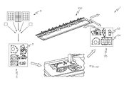
- FIG. 1 is a partly schematic illustration of an exemplary kitting arrangement and automation process according to an embodiment.
- FIG. 2 is a block diagram of an inspection system according to an embodiment.
- FIG. 3 is a side view of an exemplary inspection apparatus according to an embodiment.
- FIG. 4 is an exemplary illustration of an output of inspection information.
- FIG. 5 is another exemplary illustration of an output of inspection information.
- FIG. 6 is a block diagram of a pick and place system according to an embodiment.
- FIG. 7 is a sectional side view of an exemplary assembly apparatus according to an embodiment.
- FIG. 8 is a side view of an exemplary fastening tool according to an embodiment
- FIG. 9 is a flow chart of an exemplary process for the pick and place system of FIG. 6 .
- FIG. 1 a schematic illustration of an exemplary kitting arrangement and automation process 1 for inspecting and assembling components according to an embodiment.
- the process 1 utilizes an inspection system 10 for scanning and evaluating a component 3 retained within kit tray 5 , wherein the kit tray 5 has previously been supplied with one or more components 3 .
- the kit tray 5 may contain various parts or components such as, for example, automotive parts to be assembled. As used herein, the terms “part” and “component” are interchangeable.
- the kit tray 5 may also contain fasteners such as, for example, bolts or screws to be used to assemble the automotive parts.
- the inspection system 10 may capture information indicative of a characteristic of the component 3 and may evaluate the information relative to a stored set of data.
- the inspection system 10 may determine whether to accept the kit tray 5 , thereafter outputting a conforming kit tray 55 containing a component 53 , wherein the component 53 is one that has been accepted by the inspection system 10 .
- the process 1 further utilizes a pick and place system 100 configured to receive the conforming kit tray 55 , wherein the conforming kit tray 55 may be the kit tray 5 that passed through the inspection system 10 .
- the conforming kit tray 55 may not be the kit tray 5 , but rather may contain a component 53 matching a characteristic of an acceptable component for the process 1 .
- the pick and place system 100 is operatively configured to pick the component 53 from the conforming kit tray 55 and find a target installation position to place and install the component 53 on to a part 54 .
- FIG. 2 is a block diagram of an exemplary inspection system 10 that will be used to describe the features of the inspection system 10 in detail according to an embodiment.
- the inspection system 10 includes an inspection apparatus 20 that is operatively coupled to a controller 40 to transmit and receive information.
- the inspection apparatus 20 is operable to generate information about a component 3 undergoing inspection.
- the inspection apparatus 20 includes a holder 22 , such as a robot or robot arm, and an examination tool 30 having one or more examining devices configured to inspect or scan the component 3 .
- the examining devices may be a camera 32 , a laser 34 , or any other suitable examining devices of the sort.
- the controller 40 is operatively coupled to the inspection apparatus 20 to receive the information generated by the inspection apparatus and store or transmit data corresponding to the generated information.
- the controller 40 further includes a memory 42 that is coupled to a processor 44 to evaluate the information generated by the inspection apparatus 20 .
- the processor 44 could be a central processor unit, a microprocessor, an application-specific instruction-set processor, a digital signal processor, a specialized microprocessor, a data processor, an audio processor or the like.
- a user interface 46 such a monitor, a key pad, a touch panel or the like is connected to or in communication with the memory 42 to relay a stored data set pertaining to the component.
- a user may select the stored data set from memory 42 or enter data pertaining to the component 3 into the controller 40 using the user interface 46 to enter information into the inspection system 10 .
- the memory 42 may include a data storage device, such as a flash drive, or an optical disk drive operable to read the stored data set for the component 3 from the data storage device.
- the kit tray 5 containing one or more components 3 is received by the inspection system 10 .
- the tool 30 is operatively manipulated by the controller 40 to generate inspection information and perform measurements of the components 3 .
- the generated inspection information may include information pertaining to the absence of a component, information pertaining to the improper loading of a component, or information pertaining to the inclusion of an incorrect component, a combination of all this information, or the like.
- the measurements may also include dimensional measurements such as information about a bolt height or information about a bolt diameter.
- the controller 40 in communication with the processor 44 transmits the inspection information generated by the inspection apparatus 20 to the processor 44 , which may perform pre-programmed routines, including the generation and compilation of statistical information based upon the transferred quality inspection and dimensional information.
- the processor 44 may also perform pre-programmed comparison routines wherein the dimensional measurements are compared to a stored data set in the memory 42 pertaining to the component selected by the user interface 46 in order to determine a component 53 that is acceptable to the inspection system.
- the stored data set contains a desired characteristic that defines a conforming component such as, for example, an upper and lower tolerance limit for the height of an acceptable component or the orientation of a conforming component.
- the processor 44 is configured to continuously generate measurement information and directly provide the information to the user. The user may view the image and measurement information generated by the inspection apparatus 20 using a display device such as a monitor, a printer, or other similar devices.
- the processor 44 is configured to accept or to reject the kit tray 5 based on whether the generated measurement information of the component 3 matches the desired characteristics of the stored data set or falls within a pre-determined tolerance limits. In another embodiment, the processor may cause the inspection apparatus 20 to pause its operation when the component 3 does match the desired characteristics of the stored data in the memory 42 pertaining to the component selected by the user interface 46 .
- FIG. 3 is a side view of an exemplary inspection apparatus that will be used to describe the inspection apparatus 20 in greater detail according to an embodiment.
- the inspection apparatus 20 comprises a robot arm 26 positioned to rotatably support an examination tool 30 having at least one examining device to examine the component 3 .
- the tool 30 comprises a camera 32 and a laser 34 affixed to a surface of the tool 30 .
- the robot arm 26 , the camera 32 and the laser 34 are in communication with the processor 44 ; for example, they may each include a digital data port that is electrically coupled to the controller 40 to transfer digital data to the processor 44 .
- the inspection apparatus 20 is configured to receive the kit tray 5 containing the component 3 to undergo inspection.
- the kit tray 5 may be adapted to have an adjustable plate and operatively coupled to the inspection apparatus 20 such that the inspection apparatus 20 may determine the height of a component 3 within the kit tray 5 relative to the adjustable plate of the kit tray 5 when the component 3 undergoes inspection.
- a z-axis is substantially perpendicular to the mounting surface of the tool 30 .
- the camera 32 captures an image of the kit tray 5 and the components 3 .
- the laser 34 projects a beam substantially parallel to the z-axis on to the kit tray 5 generating information concerning the components 3 , for example, a dimensional characteristic of the component 3 such as the height of the fastener.
- the generated z-axis information is communicated to the controller 40 relaying varying information according to exemplary embodiments depicted by FIG. 4 and FIG. 5 .
- the camera 32 may output an image, for example, as shown in FIG. 4 on to a display device at the user interface 46 showing a captured image with inspection information 48 of the components 3 and of the kit tray 5 .
- the captured image with inspection information 48 may relay information about the components 3 pertaining to linear displacement, such as incorrect position or incorrect orientation of a component (e.g., part tilted).
- the captured image with inspection information 48 may also relay the absence of a component (e.g., bolt missing).
- the inspection information may indicate a component as acceptable or unacceptable, for example, by words (e.g., OK for good and NG for no good), color (e.g., green for good and red for no good), highlighted areas, or any other indicators.
- the beam projected by laser 34 may be used to generate a graphic representation, for example, as shown in FIG. 5 for display on a display device at the user interface 46 for showing graphical data with inspection information 50 of the component 3 .
- the graphical data with inspection information 50 may relay information such as, the presence of a component 3 , or indicate information pertaining to the dimensional characteristic of the component, such as whether the height of a component 3 above the adjustable plate or surface of the kit tray 5 falls within a pre-set upper and lower limit, or other quality information of the sorts. For example, if the component is above an upper height limit or below a lower height limit, then the inspection system will determine the component is the incorrect size and indicate that it is a no good (NG) part.
- NG no good
- FIG. 6 a block diagram of the pick and place system 100 will be used to describe the features of the pick and place system 100 in detail according to an embodiment.
- the pick and place system 100 includes an installation or assembly apparatus 120 that is operatively coupled to a controller 140 to transmit and receive information.
- the assembly apparatus 120 is operable to pick and place a component 53 to be installed on to a work part 54 , wherein the component 53 may be a partial engine or automotive part, for example, a water pump having fasteners such as bolts or screws retained within the water pump, and the part 54 may be a corresponding engine or automotive part that together with the component 53 make a whole engine or automotive part.
- the part 54 is positioned within the conforming kit tray 55 .
- the part 54 may not be with the conforming kit tray 55 , rather separately supplied to the pick and place system 100 .
- the assembly apparatus 120 includes a datum tool 122 having at least one datum finder configured to locate a datum reference on the part 54 .
- the datum reference serves as a locating or positioning feature for the datum tool 122 and could be, for example, a hole, a slot, a peg or a rivet situated on a surface of the part 54 .
- the datum reference may be created during the manufacturing of the part 54 .
- the assembly apparatus 120 also includes a part holder 124 operatively configured to pick up and retain at least one component 53 to be installed.
- the assembly apparatus 120 further includes a fastening tool 126 operatively configured to install the component 53 on to the part 54 .
- the controller 140 operatively coupled to the assembly apparatus 120 , includes a memory 142 that is coupled to a processor 144 and a user interface 146 .
- a user may select or enter data pertaining either the component 53 or the part 54 into the controller 140 using the user interface 146 to enter information into the pick and place system 100 .
- the memory 142 may be a data storage device, such as a flash drive, or an optical disk drive operable to read the data for a work part from the data storage device.
- FIG. 7 is a sectional view of an exemplary assembly apparatus that will be used to describe the features of the assembly apparatus 120 according to an embodiment.
- the assembly apparatus 120 comprises a datum tool 122 having datum finders 123 operatively configured to locate or contact datum references positioned on surfaces of the part 54 .
- datum finders may have tolerance limits specified to them to accommodate variations to the datum references which can occur in the manufacturing of the part 54 .
- the datum finder may be a feature such as, for example a pin, plate, pad, lug or any other features of the sorts.
- the datum tool 122 comprises a first datum finder 123 a and a second datum finder 123 b .
- the first datum finder 123 a may be a pad as shown and is configured to contact a first surface of the part 54 .
- the second datum finder 123 b may be a pin as shown, and is configured to contact a second surface of the part 54 .
- the first datum 123 a finder is configured to contact a vertical surface of the part 54
- the second datum finder 123 b is configured to contact a horizontal surface of the part 54 .
- the first datum finder 123 a and second datum finder 123 b may concurrently contact the part 54 or may separately contact the part 54 .
- the datum tool 122 further comprises a sensor (not shown) in communication with the controller 140 .
- the sensor is configured to generate a signal when the datum tool 122 locates or makes contact with the datum reference and transmit the signal to the controller 140 .
- the assembly apparatus 120 further comprises a part holder 124 operable to pick and retain the component 53 .
- the part holder is configured to retain the component 53 that may, for example, be an automotive part having a bolt or fastener retained.
- the part holder 124 is operatively coupled to the controller 140 to transfer and receive digital signals; for example, the part holder 124 may include a digital data port that is electrically coupled to the controller 140 to receive the signal from the datum tool 122 .
- the part holder 124 Upon receiving the signal, the part holder 124 places the component on to the part 54 at the installation position.
- the assembly apparatus 120 further comprises a fastening tool 126 operable to install the component 53 on to the part 54 .
- FIG. 8 is a side view of an exemplary fastening tool that will be used to describe the fastening tool 126 in greater detail according to an embodiment.
- the fastening tool 126 comprises a plurality of spindles 128 .
- the spindles 128 may be spring loaded.
- Each spindle 128 is attached to a motor 130 via a chain drive.
- Each spindle 128 further has a clutch 132 to engage and disengage each spindle 128 independently.
- the chain drive can simultaneously rotate each of the spindles 128 .
- the fastening tool 126 further comprises a datum locator 134 configured to locate a datum target on a part 54 .
- the datum target may be the same datum reference used by the datum tool 122 or may be adapted particularly for the datum locator 134 .
- the datum target may be used either as a secondary confirmation of the proper position of the part 54 or a backup check for the proper position in the event that part of the assembly apparatus is inoperative.
- the fastening tool 126 may be configured to independently engage a fastener retained in the component 53 and simultaneously secure the fastener to the part 54 .
- each spindle 128 grips a fastener 136 retained within the component 53 when the component 53 is pick from the conforming kit tray 55 and prepares for the installation of the fastener when the component 53 is on the part 54 . As the spindles are rotated, the captured fasteners will rotate thus attaching the component 53 to the part 54 at the installation position.
- step S 102 the pick and place system 100 receives a conforming kit tray 55 , wherein the conforming kit tray 55 is an accepted kit tray 5 following the inspection system 10 .
- the conforming kit tray 55 may have bypassed the inspection system 10 and, for example, undergone manual inspection.
- step S 104 the part holder 124 picks a component 53 from the conforming kit tray 55 and positions the component 53 at an installation position, wherein the installation position is a pre-determined position that may be different depending on either the component 53 , or the part 54 , or an arbitrary position in space.
- step S 106 the datum tool 122 having at least one datum finder 123 configured to locate a datum reference, locates or makes contact with at least one datum reference on the part 54 .
- step S 107 it may be determined the datum tool 122 did not locate or make contact with a datum reference on the part 54 thereby stopping the operation of the pick and place system 100 to realign the part 54 .
- the pick and place system 100 may reject the part 54 and continue operation of the pick and place system 100 .
- the pick and place system 100 may retry to contact a datum reference on the part 54 .
- step S 108 the part holder 124 places the component 53 on to the part 54 at the installation position.
- step S 110 the fastening tool 126 installs the component 53 on to the part 54 .
Abstract
A method, system and apparatus for a kitting and automation assembly. The system includes an inspection apparatus that captures information of a component. A controller is coupled to the inspection apparatus for receiving and evaluating the information to determine a conforming component. The assembly apparatus includes a datum tool that is operatively configured to contact a datum reference of a part to determine a proper position of the part. The method includes capturing a data set indicative of a characteristic of a component and comparing the data set to a stored data set having a desired characteristic to determine a conforming component. The method also includes picking and positioning the conforming component at an installation position, contacting a datum reference of a part with a datum tool to confirm a proper position, and placing the conforming component on to the part at the proper position.
Description
Current methods of automotive assembly include assembling a kit with automotive parts. However, there are some automotive parts such as bolts and fasteners required for the kit that are generally not included in the assembly of the kit but, rather, are picked up and installed individually by an assembler or an assembly line robot after the kit is assembled. This is an inefficient and time consuming process due, at least in part, to incorrect bolts, misplaced parts and incorrectly placed bolts.
In one aspect, a kitting and automation assembly process includes a method involving the steps of scanning a component and capturing a data set indicative of a characteristic of the component. The method further involves comparing the captured data set with a stored data set having a desired characteristic and determining that the component is a conforming component if the data set matches the desired characteristics of the stored data set. Thereafter, picking and positioning the conforming component at an installation position with respect to a part by contacting a datum reference of the part with a tool. The tool having a datum finder configured to locate the datum reference at a proper alignment. The tool subsequently generates a signal confirming the tool has made contact with the datum reference at the proper alignment.
In another aspect, a kit inspection system includes an inspection apparatus. The inspection apparatus having a tool configured to scan a component and capture data indicative of characteristics of the component. A controller having a stored data set establishing a desired characteristic that defines a conforming component is coupled to the inspection apparatus for receiving and comparing the data set with the stored data set to determine a conforming component.
In still another aspect, a pick and place apparatus having a tool with a datum finder is configured to make contact with a datum reference of a work part. The pick and place apparatus further includes a controller coupled to the tool having a stored data set that establishes a proper position of the work part. The pick and place apparatus further includes a part holder to pick and place a component onto a part at an installation position.
The foregoing and other aspects of the present disclosure will become apparent to those skilled in the art to which the present disclosure relates upon reading the following description with reference to the accompanying drawings, in which:
Examples will now be described more fully hereinafter with reference to the accompanying drawings in which example embodiments are shown. Whenever possible, the same reference numerals are used throughout the drawings to refer to the same or like parts. However, aspects may be embodied in many different forms and should not be construed as limited to the embodiments set forth herein.
Referring now to FIG. 1 , a schematic illustration of an exemplary kitting arrangement and automation process 1 for inspecting and assembling components according to an embodiment. The process 1 utilizes an inspection system 10 for scanning and evaluating a component 3 retained within kit tray 5, wherein the kit tray 5 has previously been supplied with one or more components 3. The kit tray 5 may contain various parts or components such as, for example, automotive parts to be assembled. As used herein, the terms “part” and “component” are interchangeable. The kit tray 5 may also contain fasteners such as, for example, bolts or screws to be used to assemble the automotive parts. Accordingly, the inspection system 10 may capture information indicative of a characteristic of the component 3 and may evaluate the information relative to a stored set of data. The inspection system 10 may determine whether to accept the kit tray 5, thereafter outputting a conforming kit tray 55 containing a component 53, wherein the component 53 is one that has been accepted by the inspection system 10.
The process 1 further utilizes a pick and place system 100 configured to receive the conforming kit tray 55, wherein the conforming kit tray 55 may be the kit tray 5 that passed through the inspection system 10. In the alternative, the conforming kit tray 55 may not be the kit tray 5, but rather may contain a component 53 matching a characteristic of an acceptable component for the process 1. The pick and place system 100 is operatively configured to pick the component 53 from the conforming kit tray 55 and find a target installation position to place and install the component 53 on to a part 54.
The controller 40 is operatively coupled to the inspection apparatus 20 to receive the information generated by the inspection apparatus and store or transmit data corresponding to the generated information. The controller 40 further includes a memory 42 that is coupled to a processor 44 to evaluate the information generated by the inspection apparatus 20. The processor 44 could be a central processor unit, a microprocessor, an application-specific instruction-set processor, a digital signal processor, a specialized microprocessor, a data processor, an audio processor or the like. A user interface 46 such a monitor, a key pad, a touch panel or the like is connected to or in communication with the memory 42 to relay a stored data set pertaining to the component. Prior to the inspection of a component, a user may select the stored data set from memory 42 or enter data pertaining to the component 3 into the controller 40 using the user interface 46 to enter information into the inspection system 10. The memory 42 may include a data storage device, such as a flash drive, or an optical disk drive operable to read the stored data set for the component 3 from the data storage device.
Turning to the operation of the inspection system 10 according to an embodiment, the kit tray 5 containing one or more components 3 is received by the inspection system 10. The tool 30 is operatively manipulated by the controller 40 to generate inspection information and perform measurements of the components 3. For example, the generated inspection information may include information pertaining to the absence of a component, information pertaining to the improper loading of a component, or information pertaining to the inclusion of an incorrect component, a combination of all this information, or the like. If the component 3 is a fastener for example, the measurements may also include dimensional measurements such as information about a bolt height or information about a bolt diameter. The controller 40 in communication with the processor 44 transmits the inspection information generated by the inspection apparatus 20 to the processor 44, which may perform pre-programmed routines, including the generation and compilation of statistical information based upon the transferred quality inspection and dimensional information.
The processor 44 may also perform pre-programmed comparison routines wherein the dimensional measurements are compared to a stored data set in the memory 42 pertaining to the component selected by the user interface 46 in order to determine a component 53 that is acceptable to the inspection system. The stored data set contains a desired characteristic that defines a conforming component such as, for example, an upper and lower tolerance limit for the height of an acceptable component or the orientation of a conforming component. In one embodiment, the processor 44 is configured to continuously generate measurement information and directly provide the information to the user. The user may view the image and measurement information generated by the inspection apparatus 20 using a display device such as a monitor, a printer, or other similar devices. In another embodiment, the processor 44 is configured to accept or to reject the kit tray 5 based on whether the generated measurement information of the component 3 matches the desired characteristics of the stored data set or falls within a pre-determined tolerance limits. In another embodiment, the processor may cause the inspection apparatus 20 to pause its operation when the component 3 does match the desired characteristics of the stored data in the memory 42 pertaining to the component selected by the user interface 46.
Still referring to FIG. 3 , a z-axis is substantially perpendicular to the mounting surface of the tool 30. The camera 32 captures an image of the kit tray 5 and the components 3. The laser 34 projects a beam substantially parallel to the z-axis on to the kit tray 5 generating information concerning the components 3, for example, a dimensional characteristic of the component 3 such as the height of the fastener. The generated z-axis information is communicated to the controller 40 relaying varying information according to exemplary embodiments depicted by FIG. 4 and FIG. 5 .
The camera 32 may output an image, for example, as shown in FIG. 4 on to a display device at the user interface 46 showing a captured image with inspection information 48 of the components 3 and of the kit tray 5. The captured image with inspection information 48 may relay information about the components 3 pertaining to linear displacement, such as incorrect position or incorrect orientation of a component (e.g., part tilted). The captured image with inspection information 48 may also relay the absence of a component (e.g., bolt missing). The inspection information may indicate a component as acceptable or unacceptable, for example, by words (e.g., OK for good and NG for no good), color (e.g., green for good and red for no good), highlighted areas, or any other indicators.
In a similar manner, the beam projected by laser 34 may be used to generate a graphic representation, for example, as shown in FIG. 5 for display on a display device at the user interface 46 for showing graphical data with inspection information 50 of the component 3. The graphical data with inspection information 50 may relay information such as, the presence of a component 3, or indicate information pertaining to the dimensional characteristic of the component, such as whether the height of a component 3 above the adjustable plate or surface of the kit tray 5 falls within a pre-set upper and lower limit, or other quality information of the sorts. For example, if the component is above an upper height limit or below a lower height limit, then the inspection system will determine the component is the incorrect size and indicate that it is a no good (NG) part.
The assembly apparatus 120 includes a datum tool 122 having at least one datum finder configured to locate a datum reference on the part 54. The datum reference serves as a locating or positioning feature for the datum tool 122 and could be, for example, a hole, a slot, a peg or a rivet situated on a surface of the part 54. The datum reference may be created during the manufacturing of the part 54. One skilled in the art will appreciate the datum reference may be created differently depending on the requirements and functionality of the work part. The assembly apparatus 120 also includes a part holder 124 operatively configured to pick up and retain at least one component 53 to be installed. The assembly apparatus 120 further includes a fastening tool 126 operatively configured to install the component 53 on to the part 54.
The controller 140, operatively coupled to the assembly apparatus 120, includes a memory 142 that is coupled to a processor 144 and a user interface 146. Prior to the installation of the component 53 to the part 54, a user may select or enter data pertaining either the component 53 or the part 54 into the controller 140 using the user interface 146 to enter information into the pick and place system 100. The memory 142 may be a data storage device, such as a flash drive, or an optical disk drive operable to read the data for a work part from the data storage device.
Referring now to FIG. 9 , a flow diagram illustrating a sequence of operations by a pick and place system 100 for installing a component 53 on to a part 54 according to an embodiment. In step S102 the pick and place system 100 receives a conforming kit tray 55, wherein the conforming kit tray 55 is an accepted kit tray 5 following the inspection system 10. In an alternative embodiment, the conforming kit tray 55 may have bypassed the inspection system 10 and, for example, undergone manual inspection. In step S104 the part holder 124 picks a component 53 from the conforming kit tray 55 and positions the component 53 at an installation position, wherein the installation position is a pre-determined position that may be different depending on either the component 53, or the part 54, or an arbitrary position in space. In step S106 the datum tool 122 having at least one datum finder 123 configured to locate a datum reference, locates or makes contact with at least one datum reference on the part 54. In optional step S107, it may be determined the datum tool 122 did not locate or make contact with a datum reference on the part 54 thereby stopping the operation of the pick and place system 100 to realign the part 54. In an alternate embodiment, the pick and place system 100 may reject the part 54 and continue operation of the pick and place system 100. In yet another embodiment, the pick and place system 100 may retry to contact a datum reference on the part 54. If the datum tool 122 does locate or make contact with a datum reference, the datum tool 122 generates a signal enabling the system 100 to proceed to step S108. In step S108 the part holder 124 places the component 53 on to the part 54 at the installation position. In step S110 the fastening tool 126 installs the component 53 on to the part 54. One skilled in the art will readily appreciate that the order of the steps in FIG. 9 may vary and the association between the features of the system may be different.
Many other example embodiments can be provided through various combinations of the above described features. Although the embodiments described hereinabove use specific examples and alternatives, it will be understood by those skilled in the art that various additional alternatives may be used and equivalents may be substituted for elements and/or steps described herein, without necessarily deviating from the intended scope of the application. Modifications may be necessary to adapt the embodiments to a particular situation or to particular needs without departing from the intended scope of the application. It is intended that the application not be limited to the particular example implementations and example embodiments described herein, but that the claims be given their broadest reasonable interpretation to cover all novel and non-obvious embodiments, literal or equivalent, disclosed or not, covered thereby.
Claims (10)
1. A method for a kitting and automation process, the method comprising the steps of:
scanning a component within a kit tray using an inspection apparatus;
capturing a data set indicative of a characteristic of the component using the inspection apparatus;
comparing the data set with a stored data set having a desired characteristic;
determining that the component is a conforming component if the data set matches the desired characteristic of the stored data set;
picking the conforming component using a part holder, wherein the part holder is adapted to retain the conforming component;
positioning the conforming component at an installation position with respect to a part, wherein positioning the conforming component further comprises:
contacting a datum reference of the part with a tool, the tool having a datum finder configured to locate the datum reference at a proper alignment;
generating a signal confirming the tool has made contact with the datum reference at the proper alignment based on the signal; and
moving the part holder to the part at the installation position and placing the conforming component on the part at the installation position, based on the signal, wherein the part holder is in operative communication with the tool to receive the signal; and
engaging at least one spindle with a fastener retained on the component, wherein the datum reference is located radially inward with respect to the spindle.
2. The method for the kitting and automation process as defined in claim 1 , further including a step of creating an image as the inspection apparatus is capturing the data set of the component.
3. The method for the kitting and automation process as defined in claim 2 , further including a step of viewing the image with a display device.
4. The method for the kitting and automation process as defined in claim 1 , further including a step of pausing the process when the component does not match the desired characteristics established by the stored data set.
5. The method for the kitting and automation process as defined in claim 1 , further including a step of stopping the process when the tool does not make contact with the datum reference.
6. A system for kit inspection, the system comprising:
an inspection apparatus having a tool operatively configured to scan a component, the tool comprising;
a laser configured to capture a dimensional characteristic of the component, and
a camera configured to sense a linear displacement of the component, wherein the tool is adapted to capture a data set indicative of a dimensional characteristic of the component and a linear displacement of the component;
a controller operatively coupled to the inspection apparatus for receiving the data set, the controller having a stored data set specific to the component for establishing a desired characteristic that defines a conforming component; and
a processor in operative communication with the controller, the processor adapted to evaluate the data set with respect to the stored data set, wherein the processor is configured to determine if the component is a conforming component based on the captured data set;
a part holder for picking the conforming component, wherein the part holder is capable of retaining the conforming component and positioning the conforming component at an installation position with respect to a part, wherein positioning the conforming component further comprises:
contacting a datum reference of the part with a tool, the tool having a datum finder configured to locate the datum reference at a proper alignment;
generating a signal confirming the tool has made contact with the datum reference at the proper alignment based on the signal; and
moving the part holder to the part at the installation position and placing the conforming component on the part at the installation position, based on the signal, wherein the part holder is in operative communication with the tool to receive the signal; and
engaging at least one spindle with a fastener retained on the component, wherein the datum reference is located radially inward with respect to the spindle.
7. The system according to claim 6 , wherein the inspection apparatus is adapted to scan a component retained within a kit tray.
8. The system according to claim 7 , wherein the kit tray is configured to have an adjustable surface.
9. The system according to claim 7 , wherein the inspection apparatus is operatively configured to scan the component relative to the adjustable surface of the kit tray.
10. The system according to claim 6 , wherein the laser projects a beam on to the component generating a graphic representation that indicates the dimensional characteristic of the component.
Priority Applications (2)
| Application Number | Priority Date | Filing Date | Title |
|---|---|---|---|
| US14/102,608 US9778650B2 (en) | 2013-12-11 | 2013-12-11 | Apparatus, system and method for kitting and automation assembly |
| US15/688,469 US10520926B2 (en) | 2013-12-11 | 2017-08-28 | Apparatus, system and method for kitting and automation assembly |
Applications Claiming Priority (1)
| Application Number | Priority Date | Filing Date | Title |
|---|---|---|---|
| US14/102,608 US9778650B2 (en) | 2013-12-11 | 2013-12-11 | Apparatus, system and method for kitting and automation assembly |
Related Child Applications (1)
| Application Number | Title | Priority Date | Filing Date |
|---|---|---|---|
| US15/688,469 Division US10520926B2 (en) | 2013-12-11 | 2017-08-28 | Apparatus, system and method for kitting and automation assembly |
Publications (2)
| Publication Number | Publication Date |
|---|---|
| US20150160650A1 US20150160650A1 (en) | 2015-06-11 |
| US9778650B2 true US9778650B2 (en) | 2017-10-03 |
Family
ID=53271092
Family Applications (2)
| Application Number | Title | Priority Date | Filing Date |
|---|---|---|---|
| US14/102,608 Active 2035-09-17 US9778650B2 (en) | 2013-12-11 | 2013-12-11 | Apparatus, system and method for kitting and automation assembly |
| US15/688,469 Expired - Fee Related US10520926B2 (en) | 2013-12-11 | 2017-08-28 | Apparatus, system and method for kitting and automation assembly |
Family Applications After (1)
| Application Number | Title | Priority Date | Filing Date |
|---|---|---|---|
| US15/688,469 Expired - Fee Related US10520926B2 (en) | 2013-12-11 | 2017-08-28 | Apparatus, system and method for kitting and automation assembly |
Country Status (1)
| Country | Link |
|---|---|
| US (2) | US9778650B2 (en) |
Cited By (2)
| Publication number | Priority date | Publication date | Assignee | Title |
|---|---|---|---|---|
| US20190001497A1 (en) * | 2017-06-28 | 2019-01-03 | Honda Motor Co., Ltd. | Robotic system and method of assembling an apparatus |
| US10955429B1 (en) * | 2017-12-06 | 2021-03-23 | National Technology & Engineering Solutions Of Sandia, Llc | Inspection workcell |
Families Citing this family (7)
| Publication number | Priority date | Publication date | Assignee | Title |
|---|---|---|---|---|
| NL2015542B1 (en) * | 2015-10-01 | 2017-04-20 | Rexnord Flattop Europe Bv | Planning system and method for maintaining a cycle time in an automobile factory. |
| CN107024189A (en) * | 2016-02-02 | 2017-08-08 | 乐华科技股份有限公司 | Transfer machine automatic senser |
| JP6333871B2 (en) * | 2016-02-25 | 2018-05-30 | ファナック株式会社 | Image processing apparatus for displaying an object detected from an input image |
| DE202016102149U1 (en) * | 2016-04-22 | 2017-07-26 | Kuka Systems Gmbh | manufacturing plant |
| US11123867B2 (en) * | 2019-05-13 | 2021-09-21 | Raytheon Company | Automated radar assembly system |
| JP2020192643A (en) * | 2019-05-28 | 2020-12-03 | 澁谷工業株式会社 | Assembly device |
| US11593931B2 (en) | 2020-06-09 | 2023-02-28 | Howmedica Osteonics Corp. | Surgical kit inspection systems and methods for inspecting surgical kits having parts of different types |
Citations (52)
| Publication number | Priority date | Publication date | Assignee | Title |
|---|---|---|---|---|
| US528393A (en) * | 1894-10-30 | James j | ||
| US4576286A (en) * | 1983-06-27 | 1986-03-18 | Cochlea Corporation | Parts sorting systems |
| US4759112A (en) | 1987-05-28 | 1988-07-26 | Emhart Enterprises Corp. | Combined sequencing and insertion machine |
| US4815190A (en) * | 1987-08-20 | 1989-03-28 | Gmf Robotics Corporation | Method for automated assembly of assemblies such as automotive assemblies |
| US4894908A (en) * | 1987-08-20 | 1990-01-23 | Gmf Robotics Corporation | Method for automated assembly of assemblies such as automotive assemblies and system utilizing same |
| US5055754A (en) * | 1988-06-01 | 1991-10-08 | Fanuc Ltd. | Apparatus for detecting an excessive position error in a servo system |
| US5149979A (en) | 1988-04-18 | 1992-09-22 | Harrow George A | Sagger loading apparatus and a method of loading a sagger |
| US5148591A (en) * | 1981-05-11 | 1992-09-22 | Sensor Adaptive Machines, Inc. | Vision target based assembly |
| US5321353A (en) * | 1992-05-13 | 1994-06-14 | Storage Technolgy Corporation | System and method for precisely positioning a robotic tool |
| US5380978A (en) * | 1991-07-12 | 1995-01-10 | Pryor; Timothy R. | Method and apparatus for assembly of car bodies and other 3-dimensional objects |
| US5542520A (en) | 1993-06-18 | 1996-08-06 | Grabener Pressensysteme Gmbh & Co. Kg | Coin testing apparatus |
| US5687831A (en) * | 1995-04-25 | 1997-11-18 | Adept Technology, Inc. | Flexible parts feeder |
| US5722148A (en) | 1994-03-31 | 1998-03-03 | Mazda Motor Corporation | Apparatus and method for assembling motor vehicle |
| US5727300A (en) | 1995-02-07 | 1998-03-17 | The Boeing Company | Fastener verification system |
| US5745972A (en) | 1989-06-22 | 1998-05-05 | Hitachi, Ltd. | Method of producing parts/substrate assemblies |
| EP0604619B1 (en) * | 1992-07-17 | 1999-01-13 | Ariel Industries Plc | Positioning a fastener applicator with respect to a workpiece |
| US5866916A (en) | 1979-04-30 | 1999-02-02 | Sensor Adaptive Machines, Inc. | Method and apparatus for electro optically determining the dimension, location and attitude of objects |
| US5953812A (en) | 1997-07-03 | 1999-09-21 | Schlumberger Technologies, Inc. | Misinsert sensing in pick and place tooling |
| US6066845A (en) * | 1997-11-14 | 2000-05-23 | Virtek Vision Corporation | Laser scanning method and system |
| US6490369B1 (en) * | 1999-07-06 | 2002-12-03 | Fanuc Robotics North America | Method of viewing and identifying a part for a robot manipulator |
| US6563130B2 (en) | 1998-10-21 | 2003-05-13 | Canadian Space Agency | Distance tracking control system for single pass topographical mapping |
| US20030090682A1 (en) * | 2000-09-13 | 2003-05-15 | Gooch Richard Michael | Positioning in computer aided manufacturing by measuring both parts (cameras, retro reflectors) |
| US6681468B1 (en) | 1999-11-05 | 2004-01-27 | Matsushita Electric Industrial Co., Ltd. | Device and method for mounting parts |
| US6804880B2 (en) * | 2001-04-26 | 2004-10-19 | Fuji Photo Film Co., Ltd. | Assembly apparatus |
| US6831287B2 (en) * | 2001-10-15 | 2004-12-14 | Multimetrixs, Llc | Method and apparatus for preventing transfer of an object having wrong dimensions or orientation |
| US6878954B2 (en) | 2001-02-22 | 2005-04-12 | Toolz, Ltd. | Detecting tool orientation, alignment, depth, and leveling |
| US20060118459A1 (en) * | 2004-12-07 | 2006-06-08 | Christensen David M | System and method for locating components on a tray |
| US7084900B1 (en) * | 1999-04-08 | 2006-08-01 | Fanuc Ltd. | Image processing apparatus |
| US7134210B2 (en) | 2004-09-30 | 2006-11-14 | The Boeing Company | Systems and methods for dimensionally inspecting threaded fasteners |
| US7165318B2 (en) | 2001-07-27 | 2007-01-23 | Matsushita Electric Industrial Co., Ltd. | Components placing apparatus |
| US7191511B2 (en) | 2003-02-25 | 2007-03-20 | Matsushita Electric Industrial Co., Ltd. | Electronic component placement machine having camera units with vertically overlaid apertures |
| US7239399B2 (en) | 2001-11-13 | 2007-07-03 | Cyberoptics Corporation | Pick and place machine with component placement inspection |
| US20070177790A1 (en) * | 2006-02-01 | 2007-08-02 | Fanuc Ltd | Workpiece picking device |
| US7313464B1 (en) * | 2006-09-05 | 2007-12-25 | Adept Technology Inc. | Bin-picking system for randomly positioned objects |
| US20080253612A1 (en) * | 2005-10-18 | 2008-10-16 | Morphic Technologies Aktiebolag | Method and an Arrangement for Locating and Picking Up Objects From a Carrier |
| US20090046921A1 (en) * | 2004-10-05 | 2009-02-19 | Cyberoptics Corporation | Pick and place machine with improved component pick up inspection |
| US7570801B2 (en) | 2006-10-27 | 2009-08-04 | Assembleon N.V. | Device suitable for placing components on a substrate |
| US20090234501A1 (en) * | 2006-05-25 | 2009-09-17 | Takehiro Ishizaki | Work Robot |
| US20100012260A1 (en) | 2007-05-22 | 2010-01-21 | Brennan Joseph D | Pre-patterned layup kit and method of manufacture |
| US20100092032A1 (en) * | 2008-10-10 | 2010-04-15 | Remus Boca | Methods and apparatus to facilitate operations in image based systems |
| US7797128B2 (en) | 2007-12-06 | 2010-09-14 | The Boeing Company | Calibration procedure for rivet height gages |
| WO2010112894A1 (en) * | 2009-04-02 | 2010-10-07 | Roke Manor Research Limited | Automated 3d article inspection |
| US20110074950A1 (en) * | 2009-09-25 | 2011-03-31 | Japan Atomic Energy Agency | Image capturing apparatus, image displaying method and recording medium, image displaying program being recorded thereon |
| US8029224B2 (en) | 2007-03-23 | 2011-10-04 | Tokyo Electron Limited | Substrate transfer apparatus, substrate transfer method, and storage medium |
| US8051547B2 (en) | 2006-12-29 | 2011-11-08 | The Boeing Company | Robot-deployed assembly tool |
| US8172074B2 (en) * | 2009-06-09 | 2012-05-08 | Xerox Corporation | Automated delivery of parts across diverse manufacturing stations |
| US8185238B2 (en) | 2007-05-28 | 2012-05-22 | Airbus Operations, S.L. | System for carrying out automatic drilling / riveting process in aeronautical assembly pieces |
| US20120165986A1 (en) * | 2009-08-27 | 2012-06-28 | Abb Research Ltd. | Robotic picking of parts from a parts holding bin |
| US20130054025A1 (en) * | 2011-08-26 | 2013-02-28 | Canon Kabushiki Kaisha | Information processing apparatus, control method for information processing apparatus, and recording medium |
| US20140100696A1 (en) * | 2012-10-04 | 2014-04-10 | Electronics And Telecommunications Research Institute | Working method using sensor and working system for performing same |
| US20140172165A1 (en) * | 2012-12-13 | 2014-06-19 | Fanuc Corporation | Robot operation system having a plurality of robots |
| US20140365007A1 (en) * | 2013-06-07 | 2014-12-11 | Matthew E. Trompeter | Visual Datum Reference Tool |
Family Cites Families (58)
| Publication number | Priority date | Publication date | Assignee | Title |
|---|---|---|---|---|
| US3822958A (en) * | 1973-06-04 | 1974-07-09 | Ekstrom Carlson & Co | Multispindle drilling machine |
| US6317953B1 (en) * | 1981-05-11 | 2001-11-20 | Lmi-Diffracto | Vision target based assembly |
| US4429463A (en) * | 1981-10-21 | 1984-02-07 | Angell Bruce R | Machinist electro-mechanical dynamic datum point locator tool |
| US5267143A (en) * | 1984-10-12 | 1993-11-30 | Sensor Adaptive Machines, Incorporated | Vision assisted fixture construction |
| US4781517A (en) * | 1986-02-03 | 1988-11-01 | Clay-Mill Technical Systems, Inc. | Robotic automobile assembly |
| US4894901A (en) * | 1986-12-22 | 1990-01-23 | The Boeing Company | Method for positioning a robotic work system |
| US4785528A (en) * | 1986-12-22 | 1988-11-22 | The Boeing Company | Robotic work positioning system |
| JPS63288683A (en) * | 1987-05-21 | 1988-11-25 | 株式会社東芝 | Assembling robot |
| US4831549A (en) * | 1987-07-28 | 1989-05-16 | Brigham Young University | Device and method for correction of robot inaccuracy |
| US5579444A (en) * | 1987-08-28 | 1996-11-26 | Axiom Bildverarbeitungssysteme Gmbh | Adaptive vision-based controller |
| US5233152A (en) * | 1989-06-21 | 1993-08-03 | Honeywell Inc. | Robotic laser soldering apparatus for automated surface assembly of microscopic components |
| US4980971A (en) * | 1989-12-14 | 1991-01-01 | At&T Bell Laboratories | Method and apparatus for chip placement |
| US5155895A (en) * | 1990-09-13 | 1992-10-20 | Massachusetts Institute Of Technology | Method and apparatus for automatic parts assembly |
| JPH04269139A (en) * | 1991-02-19 | 1992-09-25 | Sony Corp | Work holding device |
| US5272805A (en) * | 1991-04-01 | 1993-12-28 | Fanuc Robotics North America, Inc. | System for the flexible assembly of assemblies |
| US5144870A (en) * | 1991-10-18 | 1992-09-08 | Nick Edward V | Apparatus for selectively installing fasteners |
| US5265317A (en) * | 1991-12-19 | 1993-11-30 | Progressive Tool & Industries Co. | Geometry station |
| US5560102A (en) * | 1992-10-13 | 1996-10-01 | The Boeing Company | Panel and fuselage assembly |
| US5917726A (en) * | 1993-11-18 | 1999-06-29 | Sensor Adaptive Machines, Inc. | Intelligent machining and manufacturing |
| JP3012463B2 (en) * | 1993-12-22 | 2000-02-21 | 松下電工株式会社 | Assembly equipment |
| US5910894A (en) * | 1994-01-11 | 1999-06-08 | Sensor Adaptive Machines, Inc. | Sensor based assembly tooling improvements |
| US5771553A (en) * | 1996-10-03 | 1998-06-30 | National University Of Singapore | Precision and quick affixing method for flexible automated assembly |
| WO2000025185A1 (en) * | 1998-10-27 | 2000-05-04 | Irobotics, Inc. | Robotic process planning using templates |
| JP3673117B2 (en) * | 1999-06-14 | 2005-07-20 | 和泉電気株式会社 | Assembly apparatus and tray system therefor |
| US6442815B1 (en) * | 2000-04-18 | 2002-09-03 | The Regents Of The University Of Michigan | Reconfigurable automatic tool changer |
| US6467355B1 (en) * | 2001-04-16 | 2002-10-22 | Irving Leong | Most accurate method of tensioning threaded fasteners in assembled units |
| US6638139B2 (en) * | 2001-05-18 | 2003-10-28 | Acme Manufacturing Company | Multi-spindle end effector |
| GB0125079D0 (en) * | 2001-10-18 | 2001-12-12 | Cimac Automation Ltd | Auto motion:robot guidance for manufacturing |
| US6898484B2 (en) * | 2002-05-01 | 2005-05-24 | Dorothy Lemelson | Robotic manufacturing and assembly with relative radio positioning using radio based location determination |
| US6899377B2 (en) * | 2002-09-24 | 2005-05-31 | Ford Motor Company | Vehicle body |
| EP1633534B1 (en) * | 2003-04-28 | 2018-09-12 | Nikon Metrology NV | Cmm arm with exoskeleton |
| US7089826B2 (en) * | 2003-07-09 | 2006-08-15 | Ford Motor Company | Automatic tool attachment apparatus |
| US7503108B2 (en) * | 2003-07-09 | 2009-03-17 | Ford Motor Company | Multi-spindle positioning apparatus |
| US20060288577A1 (en) * | 2005-05-31 | 2006-12-28 | Hans-Juergen Bormuth | System for mounting wheels to vehicle |
| US7178255B1 (en) * | 2005-09-09 | 2007-02-20 | General Electric Company | Methods and apparatus for manufacturing components |
| US7430456B2 (en) * | 2006-02-08 | 2008-09-30 | Seagate Technology Llc | Reference point teaching using an end effector to form a witness mark |
| US8366592B2 (en) * | 2007-11-30 | 2013-02-05 | Cinetic Automation Corp. | Quick change spindle |
| US8458896B2 (en) * | 2008-11-25 | 2013-06-11 | HGST Netherlands B.V. | Robotic end-effector for component center alignment and assembly |
| DE102009018991A1 (en) * | 2009-05-01 | 2010-11-04 | Airbus Operations Gmbh | Device for the spatial alignment of at least two subassembly components and method |
| EP2269783A1 (en) * | 2009-06-30 | 2011-01-05 | Leica Geosystems AG | Calibration method for a measuring system |
| JP2011115877A (en) * | 2009-12-02 | 2011-06-16 | Canon Inc | Double arm robot |
| US8634950B2 (en) * | 2009-12-14 | 2014-01-21 | Embraer S.A. | Automated positioning and alignment method and system for aircraft structures using robots |
| US7966856B1 (en) * | 2009-12-15 | 2011-06-28 | General Electric Company | Robotic peening apparatus |
| JP5528095B2 (en) * | 2009-12-22 | 2014-06-25 | キヤノン株式会社 | Robot system, control apparatus and method thereof |
| JP5423441B2 (en) * | 2010-02-03 | 2014-02-19 | 株式会社安川電機 | Work system, robot apparatus, and manufacturing method of machine product |
| GB201009219D0 (en) * | 2010-06-02 | 2010-07-21 | Airbus Operations Ltd | Aircraft component manufacturing method and apparatus |
| JP5382035B2 (en) * | 2011-03-08 | 2014-01-08 | 株式会社安川電機 | Automatic working device |
| JP2013078825A (en) * | 2011-10-04 | 2013-05-02 | Yaskawa Electric Corp | Robot apparatus, robot system, and method for manufacturing workpiece |
| JP2013111726A (en) * | 2011-11-30 | 2013-06-10 | Sony Corp | Robot apparatus, method of controlling the same, and computer program |
| US9043011B2 (en) * | 2012-01-04 | 2015-05-26 | General Electric Company | Robotic machining apparatus method and system for turbine buckets |
| JP6039187B2 (en) * | 2012-02-03 | 2016-12-07 | キヤノン株式会社 | Assembly apparatus, gripping hand, and article assembling method |
| JP5507595B2 (en) * | 2012-02-17 | 2014-05-28 | ファナック株式会社 | Article assembling apparatus using robot |
| US8843236B2 (en) * | 2012-03-15 | 2014-09-23 | GM Global Technology Operations LLC | Method and system for training a robot using human-assisted task demonstration |
| US20130263433A1 (en) * | 2012-03-26 | 2013-10-10 | Newfrey Llc | Automated Fastener Setting Tool |
| FR2994279B1 (en) * | 2012-08-03 | 2014-08-08 | Thales Sa | METHOD FOR CONTROLLING THE INTEGRITY OF RADIO NAVIGATION STATIONS IN A SATELLITE INCREASE SYSTEM |
| JP2014069251A (en) * | 2012-09-28 | 2014-04-21 | Dainippon Screen Mfg Co Ltd | Working part control device, working robot, working part control method, and working part control program |
| US9669432B2 (en) * | 2013-08-27 | 2017-06-06 | Te Connectivity Corporation | Component feeding system |
| JP6459227B2 (en) * | 2014-06-02 | 2019-01-30 | セイコーエプソン株式会社 | Robot system |
-
2013
- 2013-12-11 US US14/102,608 patent/US9778650B2/en active Active
-
2017
- 2017-08-28 US US15/688,469 patent/US10520926B2/en not_active Expired - Fee Related
Patent Citations (53)
| Publication number | Priority date | Publication date | Assignee | Title |
|---|---|---|---|---|
| US528393A (en) * | 1894-10-30 | James j | ||
| US5866916A (en) | 1979-04-30 | 1999-02-02 | Sensor Adaptive Machines, Inc. | Method and apparatus for electro optically determining the dimension, location and attitude of objects |
| US5981965A (en) | 1979-04-30 | 1999-11-09 | Lmi-Diffracto | Method and apparatus for electro-optically determining the dimension, location and attitude of objects |
| US5148591A (en) * | 1981-05-11 | 1992-09-22 | Sensor Adaptive Machines, Inc. | Vision target based assembly |
| US4576286A (en) * | 1983-06-27 | 1986-03-18 | Cochlea Corporation | Parts sorting systems |
| US4759112A (en) | 1987-05-28 | 1988-07-26 | Emhart Enterprises Corp. | Combined sequencing and insertion machine |
| US4815190A (en) * | 1987-08-20 | 1989-03-28 | Gmf Robotics Corporation | Method for automated assembly of assemblies such as automotive assemblies |
| US4894908A (en) * | 1987-08-20 | 1990-01-23 | Gmf Robotics Corporation | Method for automated assembly of assemblies such as automotive assemblies and system utilizing same |
| US5149979A (en) | 1988-04-18 | 1992-09-22 | Harrow George A | Sagger loading apparatus and a method of loading a sagger |
| US5055754A (en) * | 1988-06-01 | 1991-10-08 | Fanuc Ltd. | Apparatus for detecting an excessive position error in a servo system |
| US5745972A (en) | 1989-06-22 | 1998-05-05 | Hitachi, Ltd. | Method of producing parts/substrate assemblies |
| US5380978A (en) * | 1991-07-12 | 1995-01-10 | Pryor; Timothy R. | Method and apparatus for assembly of car bodies and other 3-dimensional objects |
| US5321353A (en) * | 1992-05-13 | 1994-06-14 | Storage Technolgy Corporation | System and method for precisely positioning a robotic tool |
| EP0604619B1 (en) * | 1992-07-17 | 1999-01-13 | Ariel Industries Plc | Positioning a fastener applicator with respect to a workpiece |
| US5542520A (en) | 1993-06-18 | 1996-08-06 | Grabener Pressensysteme Gmbh & Co. Kg | Coin testing apparatus |
| US5722148A (en) | 1994-03-31 | 1998-03-03 | Mazda Motor Corporation | Apparatus and method for assembling motor vehicle |
| US5727300A (en) | 1995-02-07 | 1998-03-17 | The Boeing Company | Fastener verification system |
| US5687831A (en) * | 1995-04-25 | 1997-11-18 | Adept Technology, Inc. | Flexible parts feeder |
| US5953812A (en) | 1997-07-03 | 1999-09-21 | Schlumberger Technologies, Inc. | Misinsert sensing in pick and place tooling |
| US6066845A (en) * | 1997-11-14 | 2000-05-23 | Virtek Vision Corporation | Laser scanning method and system |
| US6563130B2 (en) | 1998-10-21 | 2003-05-13 | Canadian Space Agency | Distance tracking control system for single pass topographical mapping |
| US7084900B1 (en) * | 1999-04-08 | 2006-08-01 | Fanuc Ltd. | Image processing apparatus |
| US6490369B1 (en) * | 1999-07-06 | 2002-12-03 | Fanuc Robotics North America | Method of viewing and identifying a part for a robot manipulator |
| US6681468B1 (en) | 1999-11-05 | 2004-01-27 | Matsushita Electric Industrial Co., Ltd. | Device and method for mounting parts |
| US20030090682A1 (en) * | 2000-09-13 | 2003-05-15 | Gooch Richard Michael | Positioning in computer aided manufacturing by measuring both parts (cameras, retro reflectors) |
| US6878954B2 (en) | 2001-02-22 | 2005-04-12 | Toolz, Ltd. | Detecting tool orientation, alignment, depth, and leveling |
| US6804880B2 (en) * | 2001-04-26 | 2004-10-19 | Fuji Photo Film Co., Ltd. | Assembly apparatus |
| US7165318B2 (en) | 2001-07-27 | 2007-01-23 | Matsushita Electric Industrial Co., Ltd. | Components placing apparatus |
| US6831287B2 (en) * | 2001-10-15 | 2004-12-14 | Multimetrixs, Llc | Method and apparatus for preventing transfer of an object having wrong dimensions or orientation |
| US7239399B2 (en) | 2001-11-13 | 2007-07-03 | Cyberoptics Corporation | Pick and place machine with component placement inspection |
| US7191511B2 (en) | 2003-02-25 | 2007-03-20 | Matsushita Electric Industrial Co., Ltd. | Electronic component placement machine having camera units with vertically overlaid apertures |
| US7134210B2 (en) | 2004-09-30 | 2006-11-14 | The Boeing Company | Systems and methods for dimensionally inspecting threaded fasteners |
| US20090046921A1 (en) * | 2004-10-05 | 2009-02-19 | Cyberoptics Corporation | Pick and place machine with improved component pick up inspection |
| US20060118459A1 (en) * | 2004-12-07 | 2006-06-08 | Christensen David M | System and method for locating components on a tray |
| US20080253612A1 (en) * | 2005-10-18 | 2008-10-16 | Morphic Technologies Aktiebolag | Method and an Arrangement for Locating and Picking Up Objects From a Carrier |
| US20070177790A1 (en) * | 2006-02-01 | 2007-08-02 | Fanuc Ltd | Workpiece picking device |
| US20090234501A1 (en) * | 2006-05-25 | 2009-09-17 | Takehiro Ishizaki | Work Robot |
| US7313464B1 (en) * | 2006-09-05 | 2007-12-25 | Adept Technology Inc. | Bin-picking system for randomly positioned objects |
| US7570801B2 (en) | 2006-10-27 | 2009-08-04 | Assembleon N.V. | Device suitable for placing components on a substrate |
| US8051547B2 (en) | 2006-12-29 | 2011-11-08 | The Boeing Company | Robot-deployed assembly tool |
| US8029224B2 (en) | 2007-03-23 | 2011-10-04 | Tokyo Electron Limited | Substrate transfer apparatus, substrate transfer method, and storage medium |
| US20100012260A1 (en) | 2007-05-22 | 2010-01-21 | Brennan Joseph D | Pre-patterned layup kit and method of manufacture |
| US8185238B2 (en) | 2007-05-28 | 2012-05-22 | Airbus Operations, S.L. | System for carrying out automatic drilling / riveting process in aeronautical assembly pieces |
| US7797128B2 (en) | 2007-12-06 | 2010-09-14 | The Boeing Company | Calibration procedure for rivet height gages |
| US20100092032A1 (en) * | 2008-10-10 | 2010-04-15 | Remus Boca | Methods and apparatus to facilitate operations in image based systems |
| WO2010112894A1 (en) * | 2009-04-02 | 2010-10-07 | Roke Manor Research Limited | Automated 3d article inspection |
| US8172074B2 (en) * | 2009-06-09 | 2012-05-08 | Xerox Corporation | Automated delivery of parts across diverse manufacturing stations |
| US20120165986A1 (en) * | 2009-08-27 | 2012-06-28 | Abb Research Ltd. | Robotic picking of parts from a parts holding bin |
| US20110074950A1 (en) * | 2009-09-25 | 2011-03-31 | Japan Atomic Energy Agency | Image capturing apparatus, image displaying method and recording medium, image displaying program being recorded thereon |
| US20130054025A1 (en) * | 2011-08-26 | 2013-02-28 | Canon Kabushiki Kaisha | Information processing apparatus, control method for information processing apparatus, and recording medium |
| US20140100696A1 (en) * | 2012-10-04 | 2014-04-10 | Electronics And Telecommunications Research Institute | Working method using sensor and working system for performing same |
| US20140172165A1 (en) * | 2012-12-13 | 2014-06-19 | Fanuc Corporation | Robot operation system having a plurality of robots |
| US20140365007A1 (en) * | 2013-06-07 | 2014-12-11 | Matthew E. Trompeter | Visual Datum Reference Tool |
Cited By (2)
| Publication number | Priority date | Publication date | Assignee | Title |
|---|---|---|---|---|
| US20190001497A1 (en) * | 2017-06-28 | 2019-01-03 | Honda Motor Co., Ltd. | Robotic system and method of assembling an apparatus |
| US10955429B1 (en) * | 2017-12-06 | 2021-03-23 | National Technology & Engineering Solutions Of Sandia, Llc | Inspection workcell |
Also Published As
| Publication number | Publication date |
|---|---|
| US20150160650A1 (en) | 2015-06-11 |
| US10520926B2 (en) | 2019-12-31 |
| US20170357248A1 (en) | 2017-12-14 |
Similar Documents
| Publication | Publication Date | Title |
|---|---|---|
| US10520926B2 (en) | Apparatus, system and method for kitting and automation assembly | |
| CN102192715B (en) | Method of inspecting three dimensional shape | |
| US11543328B2 (en) | Automated functional testing systems and methods of making and using the same | |
| US20060075631A1 (en) | Pick and place machine with improved component pick up inspection | |
| US20110113609A1 (en) | Method and device for exchanging a battery in a vehicle | |
| US20070010969A1 (en) | Pick and place machine with improved setup and operation procedure | |
| WO2017029731A1 (en) | Nozzle cleaning device and nozzle station installation device | |
| US20060016066A1 (en) | Pick and place machine with improved inspection | |
| US20070003126A1 (en) | Method and apparatus for evaluating a component pick action in an electronics assembly machine | |
| KR102461013B1 (en) | Handler for testing electronic devices and method for adjusting teaching point thereof | |
| JP7473572B2 (en) | Method for determining whether a component device is good or bad | |
| US7090531B2 (en) | Plug-connection verification for detecting a properly made electrical plug connection | |
| CN209877889U (en) | Joint detection equipment | |
| CN101588583A (en) | Mobile testing system and mobile testing method | |
| JP4965101B2 (en) | Method for aligning the probe tip and the electrode of the object to be inspected | |
| US9134342B2 (en) | Intergrated apparatus and method for testing of semiconductor components using a turret machine | |
| JP5530261B2 (en) | Current test method for test object | |
| US10324126B2 (en) | Method and apparatus for aligning probe pins with respect to positions of electronic devices | |
| US20210065475A1 (en) | Method and system for inspecting an asset | |
| TWI698651B (en) | Apparatus and method for authentication of electronic device test stations | |
| CN209877888U (en) | Joint detection equipment | |
| CN112642752A (en) | Sorting machine for processing electronic parts | |
| CN220419172U (en) | Detection device | |
| CN216718252U (en) | Chip pin detection device | |
| TWI755942B (en) | Handler, tester, and testing equipment |
Legal Events
| Date | Code | Title | Description |
|---|---|---|---|
| AS | Assignment |
Owner name: HONDA MOTOR CO., LTD., JAPAN Free format text: ASSIGNMENT OF ASSIGNORS INTEREST;ASSIGNORS:SCELSI, JOHN M.;JONES, BRIAN G.;REEL/FRAME:031757/0018 Effective date: 20131122 |
|
| STCF | Information on status: patent grant |
Free format text: PATENTED CASE |
|
| MAFP | Maintenance fee payment |
Free format text: PAYMENT OF MAINTENANCE FEE, 4TH YEAR, LARGE ENTITY (ORIGINAL EVENT CODE: M1551); ENTITY STATUS OF PATENT OWNER: LARGE ENTITY Year of fee payment: 4 |