US9768720B2 - Method and system for estimating operation parameters of a servomotor - Google Patents
Method and system for estimating operation parameters of a servomotor Download PDFInfo
- Publication number
- US9768720B2 US9768720B2 US15/234,165 US201615234165A US9768720B2 US 9768720 B2 US9768720 B2 US 9768720B2 US 201615234165 A US201615234165 A US 201615234165A US 9768720 B2 US9768720 B2 US 9768720B2
- Authority
- US
- United States
- Prior art keywords
- servomotor
- angular velocity
- current
- initial
- control loop
- Prior art date
- Legal status (The legal status is an assumption and is not a legal conclusion. Google has not performed a legal analysis and makes no representation as to the accuracy of the status listed.)
- Expired - Fee Related
Links
Images


Classifications
-
- H—ELECTRICITY
- H02—GENERATION; CONVERSION OR DISTRIBUTION OF ELECTRIC POWER
- H02P—CONTROL OR REGULATION OF ELECTRIC MOTORS, ELECTRIC GENERATORS OR DYNAMO-ELECTRIC CONVERTERS; CONTROLLING TRANSFORMERS, REACTORS OR CHOKE COILS
- H02P23/00—Arrangements or methods for the control of AC motors characterised by a control method other than vector control
- H02P23/14—Estimation or adaptation of motor parameters, e.g. rotor time constant, flux, speed, current or voltage
-
- G—PHYSICS
- G05—CONTROLLING; REGULATING
- G05B—CONTROL OR REGULATING SYSTEMS IN GENERAL; FUNCTIONAL ELEMENTS OF SUCH SYSTEMS; MONITORING OR TESTING ARRANGEMENTS FOR SUCH SYSTEMS OR ELEMENTS
- G05B19/00—Programme-control systems
- G05B19/02—Programme-control systems electric
- G05B19/18—Numerical control [NC], i.e. automatically operating machines, in particular machine tools, e.g. in a manufacturing environment, so as to execute positioning, movement or co-ordinated operations by means of programme data in numerical form
- G05B19/416—Numerical control [NC], i.e. automatically operating machines, in particular machine tools, e.g. in a manufacturing environment, so as to execute positioning, movement or co-ordinated operations by means of programme data in numerical form characterised by control of velocity, acceleration or deceleration
-
- H—ELECTRICITY
- H02—GENERATION; CONVERSION OR DISTRIBUTION OF ELECTRIC POWER
- H02P—CONTROL OR REGULATION OF ELECTRIC MOTORS, ELECTRIC GENERATORS OR DYNAMO-ELECTRIC CONVERTERS; CONTROLLING TRANSFORMERS, REACTORS OR CHOKE COILS
- H02P21/00—Arrangements or methods for the control of electric machines by vector control, e.g. by control of field orientation
- H02P21/14—Estimation or adaptation of machine parameters, e.g. flux, current or voltage
- H02P21/143—Inertia or moment of inertia estimation
-
- H—ELECTRICITY
- H02—GENERATION; CONVERSION OR DISTRIBUTION OF ELECTRIC POWER
- H02P—CONTROL OR REGULATION OF ELECTRIC MOTORS, ELECTRIC GENERATORS OR DYNAMO-ELECTRIC CONVERTERS; CONTROLLING TRANSFORMERS, REACTORS OR CHOKE COILS
- H02P21/00—Arrangements or methods for the control of electric machines by vector control, e.g. by control of field orientation
- H02P21/14—Estimation or adaptation of machine parameters, e.g. flux, current or voltage
- H02P21/20—Estimation of torque
-
- G—PHYSICS
- G05—CONTROLLING; REGULATING
- G05B—CONTROL OR REGULATING SYSTEMS IN GENERAL; FUNCTIONAL ELEMENTS OF SUCH SYSTEMS; MONITORING OR TESTING ARRANGEMENTS FOR SUCH SYSTEMS OR ELEMENTS
- G05B2219/00—Program-control systems
- G05B2219/30—Nc systems
- G05B2219/34—Director, elements to supervisory
- G05B2219/34015—Axis controller
-
- G—PHYSICS
- G05—CONTROLLING; REGULATING
- G05B—CONTROL OR REGULATING SYSTEMS IN GENERAL; FUNCTIONAL ELEMENTS OF SUCH SYSTEMS; MONITORING OR TESTING ARRANGEMENTS FOR SUCH SYSTEMS OR ELEMENTS
- G05B2219/00—Program-control systems
- G05B2219/30—Nc systems
- G05B2219/50—Machine tool, machine tool null till machine tool work handling
- G05B2219/50185—Monitoring, detect failures, control of efficiency of machine, tool life
Definitions
- the disclosure relates to a method and a system for estimating operation parameters of a servomotor, and more particularly to a method and a system for estimating a torque constant, inertia and a friction coefficient of the servomotor.
- Servomotor systems are widely used in industries, and a reliable automatic control method of the servomotor system is needed, such that manpower cost may be reduced and productivity may be increased.
- servomotors require different operation parameters (e.g., a torque constant, inertia and a friction coefficient) for control thereof.
- an object of the disclosure is to provide a method and a system for rapidly estimating operation parameters of a servomotor.
- the method for estimating operation parameters of a servomotor is described.
- the method is to be implemented by a system that includes a current control loop for outputting an output current to the servomotor, and a control module for controlling the current control loop.
- the method includes the following steps:
- the system for estimating operation parameters of a servomotor includes a current control loop and a control module.
- the current control loop is configured to output an output current to the servomotor.
- the control module is configured to control the current control loop, and is operable to:
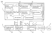
- FIG. 1 is a block diagram illustrating an embodiment of system for estimating operation parameters of a servomotor according to the disclosure
- FIG. 2 is a block diagram illustrating an embodiment of an angular position control loop of the system according to the disclosure
- FIG. 3 is a block diagram illustrating an embodiment of a rotating speed control loop of the system according to the disclosure
- FIG. 4 is a block diagram illustrating an embodiment of a current control loop of the system according to the disclosure.
- FIG. 5 is a timing diagram for illustrating timing waveforms of a current signal used to control the current control loop, an output current outputted to the servomotor, and an angular velocity of the servomotor;
- FIG. 6 is an enlarged plot for illustrating the timing waveform of the angular velocity
- FIG. 7 is a flow chart of a method for estimating the operation parameters of the servomotor according to the disclosure.
- FIG. 8 is a plot for illustrating a result of an experiment according to another embodiment for computing an estimated torque constant, an estimated friction coefficient and an estimated inertia based upon the angular velocity.
- FIG. 1 an embodiment of a system 100 for estimating operation parameters of a servomotor 4 according to this disclosure is illustrated.
- the servomotor 4 is connected to a load 2 , and the system 100 is configured to estimate the operation parameters of the servomotor 4 for controlling the servomotor 4 to stably drive the load 2 .
- the servomotor 4 is a permanent-magnet synchronous motor.
- the system 100 includes a control loop module 3 and a control module 1 .
- the control loop module 3 includes a current control loop 32 , a rotating speed control loop 31 and an angular position control loop 30 .
- the current control loop 32 is configured to output an output current to the servomotor 4 .
- the rotating speed control loop 31 is configured to drive the servomotor 4 according to an angular velocity signal.
- the angular position control loop 30 is configured to generate the angular velocity signal outputted to the rotating speed control loop 31 .
- the control module 1 is configured to control the current control loop 32 and the rotating speed control loop 31 .
- the control module 1 is a computer provided with a software and/or a firmware.
- the control module 1 is programmed to cooperate with the control loop module 3 to implement a method for estimating the operation parameters of the servomotor 4 according to this disclosure, so that the servomotor 4 loaded with the load 2 can be controlled, for example by the control loop module 3 , according to the operation parameters.
- the system 100 is configured to compute the operation parameters, such as an estimated torque constant ⁇ circumflex over (K) ⁇ t , an estimated inertia ⁇ and an estimated friction coefficient ⁇ circumflex over (B) ⁇ , of the servomotor 4 loaded with the load 2 .
- the operation parameters such as an estimated torque constant ⁇ circumflex over (K) ⁇ t , an estimated inertia ⁇ and an estimated friction coefficient ⁇ circumflex over (B) ⁇
- a symbol with a “*” represents a value of an instruction signal, e.g., ⁇ * represents an angular velocity value of the angular velocity signal for instructing the rotating speed control loop 31 .
- a symbol with a “ ⁇ ” represents an estimated quantity, e.g., ⁇ represents the estimated inertia.
- a symbol without any tag represents an actual physical quantity, e.g., J represents an actual inertia.
- FIG. 2 Block diagrams of the angular position control loop 30 , the rotating speed control loop 31 and the current control loop 32 are illustrated in FIG. 2 , FIG. 3 and FIG. 4 , respectively.
- a transfer function of the angular position control loop 30 is, but is not limited to,
- ⁇ ⁇ ( s ) ⁇ * ⁇ ( s ) K p_p s + K p_p , where ⁇ is an angle value of an angular position of the servomotor 4 , ⁇ * is an angle value of an angle signal for instructing the angular position control loop 30 , K p _ p is a proportional gain of the angular position control loop 30 associated with a cutoff frequency and a bandwidth of the angular position control loop 30 , and s is a complex frequency parameter.
- a transfer function of the rotating speed control loop 31 is, but is not limited to,
- the rotating speed control loop 31 is implemented by a proportional integral controller (PI controller).
- PI controller proportional integral controller
- the rotating speed control loop 31 computes a difference by subtracting the angular velocity value of the actual angular velocity ⁇ of the servomotor 4 from the angular velocity value of the angular velocity signal ⁇ *, which is generated by the angle control loop 30 .
- the rotating speed control loop 31 processes the difference with reference to the integral gain K i _ ⁇ and a proportional gain K p _ ⁇ of the rotating speed control loop 31 so as to obtain a torque value of a torque signal T* e .
- values of the integral gain K i _ ⁇ and the proportional gain K p _ ⁇ are to be solved herein.
- the torque value of the torque signal T* e is divided by the estimated torque constant ⁇ circumflex over (K) ⁇ t to obtain a current value of a current signal i*.
- the current signal is used to instruct the current control loop 32 , and has a d-axis component i* d and a q-axis component i* q .
- the current control loop 32 includes a q-axis control loop 321 and a d-axis control loop 322 .
- a transfer function of the q-axis control loop 321 is, but is not limited to,
- the d-axis control loop 322 has a transfer function similar to that of the q-axis control loop 322 .
- i d is a d-axis component of the output current
- i* d is the d-axis component of the current signal
- K p _ id is a proportional gain of the d-axis control loop 322
- L d is a d-axis inductance
- ⁇ id is a bandwidth of the d-axis control loop 322 .
- the transfer function of the q-axis control loop 321 of the current control loop 32 is approximated by one, which means that the q-axis component of the current signal i* q is approximately equal to the q-axis component i q of the output current
- an actual motor torque T e of the servomotor 4 is equal to the q-axis component i q of the output current multiplied by a torque constant K t .
- the angular velocity value of the actual angular velocity ⁇ of the servomotor 4 is derived from a difference between the actual motor torque T e of the servomotor 4 and an actual load torque T L of the load 2 with reference to the actual inertia J and an actual friction coefficient B.
- a difference between the q-axis component i* q of the current signal and the q-axis component i q of the output current that is fedback to an input of the q-axis control loop 321 is processed with reference to the proportional gain K p _ iq and an integral gain K i _ iq of the q-axis control loop 321 , and then combined with a q-axis component ⁇ q0 of an initial voltage, so as to obtain a q-axis component ⁇ q of an output voltage outputted to the servomotor 4 .
- a difference between the d-axis component i* d of the current signal and the d-axis component i d of the output current that is fedback to an input of the d-axis control loop 322 is processed with reference to the proportional gain K p _ id and an integral gain K i _ id of the d-axis control loop 322 , and then combined with a d-axis component ⁇ d0 of the initial voltage, so as to obtain a d-axis component ⁇ d of the output voltage.
- i* d 0
- the q-axis component i* q of the current signal is considered in the following description, and the d-axis control loop 322 may be omitted in other embodiments.
- the control module 1 includes a current configuring unit 11 , an initial-voltage configuring unit 12 , a torque-constant estimating unit 13 , an initial-inertia estimating unit 14 , a friction-coefficient estimating unit 15 , an inertia estimating unit 16 , a first calculator 171 and a second calculator 172 .
- the current configuring unit 11 generates the q-axis component i* q of the current signal for the current control loop 32 , and the current control loop 32 drives the servomotor 4 to rotate stably at an initial angular velocity ⁇ 0 by limiting the integrated value of the difference between the current value of the current signal i* and a current value of the output current.
- the initial-voltage configuring unit 12 of the control module 1 computes the d-axis component ⁇ d0 and the q-axis component ⁇ q0 of the initial voltage, and outputs the d- and q-axis components ⁇ d0 , ⁇ q0 of the initial voltage to the current control loop 32 for accelerating the servomotor 4 from the initial angular velocity ⁇ 0 to a predetermined angular velocity ⁇ 1 by feed-forward control and by relaxing the limitation of the integrated value.
- the control module 1 then computes at least one operation parameter of the servomotor 4 after the servomotor 4 rotates at the predetermined angular velocity ⁇ 1 .
- the torque-constant estimating unit 13 computes an initial estimated torque constant ⁇ circumflex over (K) ⁇ t0 .
- the first calculator 171 computes an initial proportional gain K p _ ⁇ 0 and an initial integral gain K i _ ⁇ 0 of the rotating speed control loop 31 based upon the initial estimated torque constant ⁇ circumflex over (K) ⁇ t0 and the initial estimated inertia ⁇ 0 , and then controls the rotating speed control loop 31 with the initial proportional gain K p _ ⁇ 0 and the initial integral gain K i _ ⁇ 0 .
- control module 1 measures the q-axis component i q of the output current which corresponds to the predetermined angular velocity ⁇ 1 .
- the torque-constant estimating unit 13 computes the estimated torque constant ⁇ circumflex over (K) ⁇ t
- the friction-coefficient estimating unit 15 computes the estimated friction coefficient ⁇ circumflex over (B) ⁇ .
- the inertia estimating unit 16 computes the estimated inertia ⁇ using curve fitting based upon a plurality of angular velocity values and the estimated friction coefficient ⁇ circumflex over (B) ⁇ .
- the second calculator 172 computes a proportional gain K p _ ⁇ and an integral gain K i _ ⁇ for controlling the rotating speed control loop 31 based upon the estimated torque constant ⁇ circumflex over (K) ⁇ t and the estimated friction coefficient ⁇ circumflex over (B) ⁇ .
- step S 1 the current configuring unit 11 of the control module 1 outputs the q-axis component i* q of the current signal to the current control loop 32 to enable the current control loop 32 to output the q-axis component i q of the output current to the servomotor 4 .
- the current control loop 32 drives the servomotor 4 to rotate stably at the initial angular velocity ⁇ 0 by limiting the integrated value of the difference between the q-axis component i* q of the current signal and the q-axis component i q of the output current.
- the initial-voltage configuring unit 12 computes d- and q-axis components ⁇ d0 and ⁇ q0 of the initial voltage when the servomotor 4 rotates at the initial angular velocity ⁇ 0 .
- P are pole pair of servomotor
- ⁇ is a physical quantity of flux linkage.
- the initial-voltage configuring unit 12 outputs the initial voltage having the d- and q-axis components ⁇ d0 and ⁇ q0 to the current control loop 32 , so that the servomotor 4 is accelerated by feed-forward control.
- the q-axis component i q of the output current follows the q-axis component i* q of the current signal.
- the control module 1 commands the current control loop 32 to relax the limitation of the integrated value, so as to accelerate the servomotor 4 to achieve the predetermined angular velocity ⁇ 1 at instant t 3 .
- step S 4 the servomotor 4 stably rotates at the predetermined angular velocity ⁇ 1 , and the torque-constant estimating unit 13 computes the initial estimated torque constant ⁇ circumflex over (K) ⁇ t0 based upon
- the initial-inertia estimating unit 14 computes the initial estimated inertia ⁇ 0 based upon
- J ⁇ 0 K ⁇ t ⁇ ⁇ 0 ⁇ i 1 ⁇
- ⁇ is a current angular acceleration of the servomotor 4 accelerating from the initial angular velocity ⁇ 0 to the predetermined angular velocity ⁇ 1
- the control module 1 controls the rotating speed control loop 31 with the initial proportional gain K p _ ⁇ 0 and the initial integral gain K i _ ⁇ 0 . It is worth noting that in FIG.
- the angular velocity value of the actual angular velocity ⁇ of the servomotor 4 decreases slightly at the beginning of the duration t 3 -t 4 .
- the angular velocity value of the actual angular velocity ⁇ recovers eventually to the predetermined angular velocity ⁇ 1 after the rotating speed control loop 31 controls the servomotor 4 with the initial proportional gain K p _ ⁇ 0 and the initial integral gain K i _ ⁇ 0 .
- the torque-constant estimating unit 13 computes the estimated torque constant ⁇ circumflex over (K) ⁇ t of the servomotor 4 based upon
- B ⁇ K ⁇ t ⁇ i 3 ⁇ 1 , where r s is a resistance value of the servomotor 4 , and i 3 is the q-axis component i q of the output current measured when the servomotor rotates 4 at the predetermined angular velocity ⁇ 1 in the duration t 3 -t 4 .
- the control module 1 deactivates the servomotor 4 so as to make the servomotor 4 decelerate for computing the estimated inertia ⁇ .
- the inertia estimating unit 16 samples a plurality of angular velocity values ⁇ d1 to ⁇ dn during deceleration of the servomotor 4 , i.e., in duration t 5 -t 6 , and computes the estimated inertia ⁇ using curve fitting.
- the estimated inertia ⁇ is computed based upon
- the duration for estimating the operation parameters by the method of this disclosure is only about 1.4 seconds.
- the system 100 is capable of estimating the operation parameters of the servomotor 4 and computing the proportional gain K p _ ⁇ and the integral gain K i _ ⁇ according to the operation parameters for automatically controlling the servomotor 4 within about 1.4 seconds.
- the operation parameters such as the estimated inertia ⁇ , the estimated friction coefficient ⁇ circumflex over (B) ⁇ and the estimated torque constant ⁇ circumflex over (K) ⁇ t , are automatically, precisely and rapidly computed during operation of the servomotor 4 . So-called dynamic performance, i.e. automatically and rapidly tuning the operation parameters for control of the servomotor 4 , is achieved.
Abstract
Description
where θ is an angle value of an angular position of the
where ω is an angular velocity value of an actual angular velocity of the
where iq is a q-axis component of the output current, i*q is the q-axis component of the current signal, Kp _ iq is a proportional gain of the q-
It is known that an actual motor torque Te of the
νd0=−ω0 ×P×L q ×i q, and
νq0=ω0 ×P×L d ×i d+ω0 ×P×λ,
where Ld and Lq are respectively d- and q-axis components of inductance, P are pole pair of servomotor, and λ is a physical quantity of flux linkage. Reference may be made to “Permanent Magnet Synchronous and Brushless DC Motor Drives,” 2010 (Ch. 3, pages 227-233) for calculation of the physical quantity of the flux linkage.
where ω is the angular velocity value of the actual angular velocity of the
where α is a current angular acceleration of the
and the friction-
where rs is a resistance value of the
where N is a constant associated with time solved by the curve fitting with an exponential function ω(t)=M·eN·t, and M is a constant associated with the angular velocity of the
during acceleration of the
during deceleration of the
| TABLE 1 | |||
| Manual | |||
| setting value | Estimation | Error | |
| Inertia | 3.28 × 10⁻⁴ | 3.44 × 10⁴ | 5.0% |
| (kg · m2) | |||
|
|
2.33 × 10⁻³ | 2.45 × 10⁻³ | 5.1% |
|
|
4.86 × 10⁻¹ | 4.78 × 10⁻¹ | 1.5% |
Claims (16)
νd0=−ω0 ×P×L q ×i q, and
νq0=ω0 ×P×L d ×i d+ω0 ×P×λ,
νd0=−ω0 ×P×L q ×i q, and
νq0=ω0 ×P×L d ×i d+ω0 ×P×λ,
Applications Claiming Priority (4)
| Application Number | Priority Date | Filing Date | Title |
|---|---|---|---|
| TW104108079 | 2015-03-13 | ||
| CN201510500888.XA CN105978428B (en) | 2015-03-13 | 2015-08-14 | servo motor system and control method thereof |
| CN201510500888.X | 2015-08-14 | ||
| CN201510500888 | 2015-08-14 |
Publications (2)
| Publication Number | Publication Date |
|---|---|
| US20170045870A1 US20170045870A1 (en) | 2017-02-16 |
| US9768720B2 true US9768720B2 (en) | 2017-09-19 |
Family
ID=56988351
Family Applications (1)
| Application Number | Title | Priority Date | Filing Date |
|---|---|---|---|
| US15/234,165 Expired - Fee Related US9768720B2 (en) | 2015-03-13 | 2016-08-11 | Method and system for estimating operation parameters of a servomotor |
Country Status (3)
| Country | Link |
|---|---|
| US (1) | US9768720B2 (en) |
| CN (1) | CN105978428B (en) |
| TW (1) | TWI551007B (en) |
Families Citing this family (8)
| Publication number | Priority date | Publication date | Assignee | Title |
|---|---|---|---|---|
| US10822024B2 (en) * | 2017-11-06 | 2020-11-03 | Steering Solutions Ip Holding Corporation | Current sensor fault mitigation for steering systems with permanent magnet DC drives |
| JP6740265B2 (en) * | 2018-02-16 | 2020-08-12 | ファナック株式会社 | Parameter determination support device and program |
| US10855211B2 (en) * | 2018-03-09 | 2020-12-01 | Trane International Inc. | Self-calibration of ECM motor and variable frequency drive inferred torque |
| CN110278232B (en) * | 2018-03-16 | 2021-08-17 | 腾讯科技(深圳)有限公司 | Method, device and system for controlling data downloading |
| JP6721628B2 (en) * | 2018-04-12 | 2020-07-15 | ファナック株式会社 | Parameter determination support device and program |
| TWI676871B (en) * | 2019-01-08 | 2019-11-11 | 東元電機股份有限公司 | Motor command converging device and method thereof |
| TWI739620B (en) * | 2020-10-05 | 2021-09-11 | 東元電機股份有限公司 | Velocity feedforward adjustment system and method thereof |
| TWI805353B (en) * | 2022-01-25 | 2023-06-11 | 台達電子工業股份有限公司 | Servo actuator and fast self-tuning method of gain for using the same |
Citations (16)
| Publication number | Priority date | Publication date | Assignee | Title |
|---|---|---|---|---|
| US20050137739A1 (en) * | 1999-10-20 | 2005-06-23 | Makino Milling Machine Co., Ltd. | Method of controlling numerically controlled machine tool and numerically controlled machine tool |
| US6940251B1 (en) * | 2004-04-30 | 2005-09-06 | Honeywell International Inc. | Decoupling of cross coupling for floating reference frame controllers for sensorless control of synchronous machines |
| US20060069481A1 (en) * | 2004-09-27 | 2006-03-30 | Nissan Motor Co., Ltd. | Vehicular steering control apparatus |
| US20060097688A1 (en) * | 2004-11-09 | 2006-05-11 | Patel Nitinkumar R | Start-up and restart of interior permanent magnet machines |
| US7088077B2 (en) * | 2004-11-09 | 2006-08-08 | General Motors Corporation | Position-sensorless control of interior permanent magnet machines |
| US20060250101A1 (en) * | 2005-04-13 | 2006-11-09 | Oussama Khatib | Torque-position transformer for task control of position controlled robots |
| US7339344B2 (en) * | 2005-08-25 | 2008-03-04 | International Rectifier Corporation | Self tuning method and apparatus for permanent magnet sensorless control |
| US20080067960A1 (en) * | 2004-11-24 | 2008-03-20 | Nsk, Ltd. | Unconnected Motor, Drive Control Device Thereof, And Electric Power Steering Device Using Drive Control Device Of Unconnected Motor |
| US20080258670A1 (en) * | 2007-04-23 | 2008-10-23 | Honda Motor Co., Ltd. | Open-Loop Torque Control on Joint Position-Controlled Robots |
| US20100000815A1 (en) * | 2006-10-31 | 2010-01-07 | Xiaohua Tang | Control Method of Electromotor |
| US20110050146A1 (en) * | 2009-08-28 | 2011-03-03 | Fanuc Ltd | Controller of electric motor having function of estimating inertia and friction simultaneously |
| US20110285337A1 (en) * | 2010-05-20 | 2011-11-24 | Shun Taniguchi | Control device of a synchronous motor |
| US20130026963A1 (en) * | 2011-07-27 | 2013-01-31 | Fanuc Corporation | Electric motor controller comprising function for simultaneously estimating inertia, friction, and spring |
| US20130063068A1 (en) * | 2010-07-14 | 2013-03-14 | Mitsubishi Electric Corporation | Motor control device |
| US20140265952A1 (en) * | 2013-03-15 | 2014-09-18 | Texas Instruments Incorporated | Automated Motor Control |
| US20140368137A1 (en) * | 2012-03-01 | 2014-12-18 | Kabushiki Kaisha Toshiba | Motor control device and control method thereof |
Family Cites Families (8)
| Publication number | Priority date | Publication date | Assignee | Title |
|---|---|---|---|---|
| TW483218B (en) * | 2000-04-18 | 2002-04-11 | Tian-Hua Liou | Three-phase AC motor shaft position (angle) estimating method |
| CN1171076C (en) * | 2000-08-11 | 2004-10-13 | 刘向群 | Virtual test system of permanent-magnet DC motor |
| CN1983794A (en) * | 2005-08-25 | 2007-06-20 | 国际整流器公司 | Self tuning method and apparatus for permanent magnet sensorless control |
| TWI275238B (en) * | 2006-01-02 | 2007-03-01 | Tian-Hua Liu | Rotor position/speed estimating method for micro permanent magnet synchronous motors |
| CN102355193A (en) * | 2011-09-30 | 2012-02-15 | 哈尔滨工业大学 | On-line rotational inertia identification device for alternate current permanent magnet servo system and identification method |
| TWM438070U (en) * | 2011-12-23 | 2012-09-21 | Shun-Yuan Wang | Fuzzy estimation control driving device for Induction motor stator resistance and speed |
| TWM435775U (en) * | 2011-12-23 | 2012-08-11 | Shun-Yuan Wang | With adaptive speed and stator resistor estimator of induction motor driving device |
| CN104242770B (en) * | 2014-10-09 | 2017-02-01 | 南京科远驱动技术有限公司 | Alternating-current servo system speed loop controller parameter self-tuning method |
-
2015
- 2015-08-14 TW TW104126566A patent/TWI551007B/en not_active IP Right Cessation
- 2015-08-14 CN CN201510500888.XA patent/CN105978428B/en not_active Expired - Fee Related
-
2016
- 2016-08-11 US US15/234,165 patent/US9768720B2/en not_active Expired - Fee Related
Patent Citations (25)
| Publication number | Priority date | Publication date | Assignee | Title |
|---|---|---|---|---|
| US20050137739A1 (en) * | 1999-10-20 | 2005-06-23 | Makino Milling Machine Co., Ltd. | Method of controlling numerically controlled machine tool and numerically controlled machine tool |
| US6940251B1 (en) * | 2004-04-30 | 2005-09-06 | Honeywell International Inc. | Decoupling of cross coupling for floating reference frame controllers for sensorless control of synchronous machines |
| US20060069481A1 (en) * | 2004-09-27 | 2006-03-30 | Nissan Motor Co., Ltd. | Vehicular steering control apparatus |
| US7860624B2 (en) * | 2004-09-27 | 2010-12-28 | Nissan Motor Co., Ltd. | Vehicular steering control apparatus |
| US7211984B2 (en) * | 2004-11-09 | 2007-05-01 | General Motors Corporation | Start-up and restart of interior permanent magnet machines |
| US7088077B2 (en) * | 2004-11-09 | 2006-08-08 | General Motors Corporation | Position-sensorless control of interior permanent magnet machines |
| US20060097688A1 (en) * | 2004-11-09 | 2006-05-11 | Patel Nitinkumar R | Start-up and restart of interior permanent magnet machines |
| US20080067960A1 (en) * | 2004-11-24 | 2008-03-20 | Nsk, Ltd. | Unconnected Motor, Drive Control Device Thereof, And Electric Power Steering Device Using Drive Control Device Of Unconnected Motor |
| US7405531B2 (en) * | 2005-04-13 | 2008-07-29 | The Board Of Trustees Of The Leland Stanford Junior University | Torque-position transformer for task control of position controlled robots |
| US20060250101A1 (en) * | 2005-04-13 | 2006-11-09 | Oussama Khatib | Torque-position transformer for task control of position controlled robots |
| US7339344B2 (en) * | 2005-08-25 | 2008-03-04 | International Rectifier Corporation | Self tuning method and apparatus for permanent magnet sensorless control |
| US20100000815A1 (en) * | 2006-10-31 | 2010-01-07 | Xiaohua Tang | Control Method of Electromotor |
| US8207701B2 (en) * | 2006-10-31 | 2012-06-26 | Byd Company, Ltd. | Control method of electromotor |
| US20080258670A1 (en) * | 2007-04-23 | 2008-10-23 | Honda Motor Co., Ltd. | Open-Loop Torque Control on Joint Position-Controlled Robots |
| US7986118B2 (en) * | 2007-04-23 | 2011-07-26 | Honda Motor Co., Ltd. | Open-loop torque control on joint position-controlled robots |
| US8232758B2 (en) * | 2009-08-28 | 2012-07-31 | Fanuc Ltd | Controller of electric motor having function of estimating inertia and friction simultaneously |
| US20110050146A1 (en) * | 2009-08-28 | 2011-03-03 | Fanuc Ltd | Controller of electric motor having function of estimating inertia and friction simultaneously |
| US20110285337A1 (en) * | 2010-05-20 | 2011-11-24 | Shun Taniguchi | Control device of a synchronous motor |
| US8519649B2 (en) * | 2010-05-20 | 2013-08-27 | Toshiba Corporation | Control device of a synchronous motor |
| US20130063068A1 (en) * | 2010-07-14 | 2013-03-14 | Mitsubishi Electric Corporation | Motor control device |
| US8860355B2 (en) * | 2010-07-14 | 2014-10-14 | Mitsubishi Electric Corporation | Motor control device |
| US20130026963A1 (en) * | 2011-07-27 | 2013-01-31 | Fanuc Corporation | Electric motor controller comprising function for simultaneously estimating inertia, friction, and spring |
| US8872463B2 (en) * | 2011-07-27 | 2014-10-28 | Fanuc Corporation | Electric motor controller comprising function for simultaneously estimating inertia, friction, and spring |
| US20140368137A1 (en) * | 2012-03-01 | 2014-12-18 | Kabushiki Kaisha Toshiba | Motor control device and control method thereof |
| US20140265952A1 (en) * | 2013-03-15 | 2014-09-18 | Texas Instruments Incorporated | Automated Motor Control |
Also Published As
| Publication number | Publication date |
|---|---|
| CN105978428A (en) | 2016-09-28 |
| US20170045870A1 (en) | 2017-02-16 |
| CN105978428B (en) | 2019-07-26 |
| TWI551007B (en) | 2016-09-21 |
| TW201633669A (en) | 2016-09-16 |
Similar Documents
| Publication | Publication Date | Title |
|---|---|---|
| US9768720B2 (en) | Method and system for estimating operation parameters of a servomotor | |
| US7339344B2 (en) | Self tuning method and apparatus for permanent magnet sensorless control | |
| JP6367332B2 (en) | Inverter control device and motor drive system | |
| JP6014401B2 (en) | Electric motor control device | |
| EP2075906A1 (en) | Vector controller of permanent magnet synchronous motor | |
| JPH08280199A (en) | Sensor-less controller for permanent-magnet field synchronous motor | |
| EP2945280B1 (en) | Apparatus for controlling induction machine | |
| JP6726390B2 (en) | Controller for permanent magnet type synchronous motor | |
| EP3872981A1 (en) | Motor control method and device, and frequency conversion controller | |
| CN102710205A (en) | Orientation control system and method for asynchronous motor | |
| JP2001186800A (en) | Controller for permanent-magnet synchronous motor | |
| US6777906B1 (en) | Method of controlling induction motor | |
| US20180198398A1 (en) | System and method for controlling a motor | |
| EP2345615B1 (en) | Elevator control apparatus | |
| JP6966978B2 (en) | Machine tool motor drive | |
| JPH11252994A (en) | Device and method for control of stepping motor | |
| JP3053121B2 (en) | Control method of induction motor | |
| JP6653391B2 (en) | Motor control system and motor control method | |
| US7088072B2 (en) | Motor control system | |
| JP2019187178A (en) | Motor control device | |
| WO2024071277A1 (en) | Motor control device | |
| JP2001204199A (en) | Control unit of permanent magnet type synchronous motor | |
| KR102567726B1 (en) | Motor control method, motor driving device, industrial robot control method, and industrial robot | |
| JP2001197767A (en) | Motor control device | |
| JP6787006B2 (en) | Motor control device |
Legal Events
| Date | Code | Title | Description |
|---|---|---|---|
| AS | Assignment |
Owner name: LITE-ON TECHNOLOGY CORP., TAIWAN Free format text: ASSIGNMENT OF ASSIGNORS INTEREST;ASSIGNORS:YANG, SHENG-MING;LIN, KUANG-WEI;REEL/FRAME:039405/0802 Effective date: 20160804 Owner name: LITE-ON ELECTRONICS (GUANGZHOU) LIMITED, CHINA Free format text: ASSIGNMENT OF ASSIGNORS INTEREST;ASSIGNORS:YANG, SHENG-MING;LIN, KUANG-WEI;REEL/FRAME:039405/0802 Effective date: 20160804 |
|
| STCF | Information on status: patent grant |
Free format text: PATENTED CASE |
|
| FEPP | Fee payment procedure |
Free format text: MAINTENANCE FEE REMINDER MAILED (ORIGINAL EVENT CODE: REM.); ENTITY STATUS OF PATENT OWNER: LARGE ENTITY |
|
| LAPS | Lapse for failure to pay maintenance fees |
Free format text: PATENT EXPIRED FOR FAILURE TO PAY MAINTENANCE FEES (ORIGINAL EVENT CODE: EXP.); ENTITY STATUS OF PATENT OWNER: LARGE ENTITY |
|
| STCH | Information on status: patent discontinuation |
Free format text: PATENT EXPIRED DUE TO NONPAYMENT OF MAINTENANCE FEES UNDER 37 CFR 1.362 |
|
| FP | Lapsed due to failure to pay maintenance fee |
Effective date: 20210919 |