US9726004B2 - Downhole position sensor - Google Patents
Downhole position sensor Download PDFInfo
- Publication number
- US9726004B2 US9726004B2 US14/400,417 US201314400417A US9726004B2 US 9726004 B2 US9726004 B2 US 9726004B2 US 201314400417 A US201314400417 A US 201314400417A US 9726004 B2 US9726004 B2 US 9726004B2
- Authority
- US
- United States
- Prior art keywords
- stimuli
- string
- location
- wellbore
- completion
- Prior art date
- Legal status (The legal status is an assumption and is not a legal conclusion. Google has not performed a legal analysis and makes no representation as to the accuracy of the status listed.)
- Active, expires
Links
- 238000004891 communication Methods 0.000 claims abstract description 21
- 239000000835 fiber Substances 0.000 claims description 50
- 239000004576 sand Substances 0.000 claims description 25
- 238000000034 method Methods 0.000 claims description 7
- 230000015572 biosynthetic process Effects 0.000 description 4
- 239000004215 Carbon black (E152) Substances 0.000 description 2
- 238000000429 assembly Methods 0.000 description 2
- 230000000712 assembly Effects 0.000 description 2
- 239000012530 fluid Substances 0.000 description 2
- 229930195733 hydrocarbon Natural products 0.000 description 2
- 125000001183 hydrocarbyl group Chemical group 0.000 description 2
- 238000003780 insertion Methods 0.000 description 2
- 230000037431 insertion Effects 0.000 description 2
- 238000004519 manufacturing process Methods 0.000 description 2
- 238000009987 spinning Methods 0.000 description 2
- 230000006978 adaptation Effects 0.000 description 1
- 230000003247 decreasing effect Effects 0.000 description 1
- 238000005553 drilling Methods 0.000 description 1
- 238000012986 modification Methods 0.000 description 1
- 230000004048 modification Effects 0.000 description 1
- 239000002915 spent fuel radioactive waste Substances 0.000 description 1
Images


Classifications
-
- E—FIXED CONSTRUCTIONS
- E21—EARTH DRILLING; MINING
- E21B—EARTH DRILLING, e.g. DEEP DRILLING; OBTAINING OIL, GAS, WATER, SOLUBLE OR MELTABLE MATERIALS OR A SLURRY OF MINERALS FROM WELLS
- E21B47/00—Survey of boreholes or wells
- E21B47/09—Locating or determining the position of objects in boreholes or wells, e.g. the position of an extending arm; Identifying the free or blocked portions of pipes
-
- E—FIXED CONSTRUCTIONS
- E21—EARTH DRILLING; MINING
- E21B—EARTH DRILLING, e.g. DEEP DRILLING; OBTAINING OIL, GAS, WATER, SOLUBLE OR MELTABLE MATERIALS OR A SLURRY OF MINERALS FROM WELLS
- E21B17/00—Drilling rods or pipes; Flexible drill strings; Kellies; Drill collars; Sucker rods; Cables; Casings; Tubings
- E21B17/02—Couplings; joints
- E21B17/023—Arrangements for connecting cables or wirelines to downhole devices
- E21B17/026—Arrangements for fixing cables or wirelines to the outside of downhole devices
-
- E—FIXED CONSTRUCTIONS
- E21—EARTH DRILLING; MINING
- E21B—EARTH DRILLING, e.g. DEEP DRILLING; OBTAINING OIL, GAS, WATER, SOLUBLE OR MELTABLE MATERIALS OR A SLURRY OF MINERALS FROM WELLS
- E21B17/00—Drilling rods or pipes; Flexible drill strings; Kellies; Drill collars; Sucker rods; Cables; Casings; Tubings
- E21B17/20—Flexible or articulated drilling pipes, e.g. flexible or articulated rods, pipes or cables
- E21B17/206—Flexible or articulated drilling pipes, e.g. flexible or articulated rods, pipes or cables with conductors, e.g. electrical, optical
-
- E21B47/065—
-
- E—FIXED CONSTRUCTIONS
- E21—EARTH DRILLING; MINING
- E21B—EARTH DRILLING, e.g. DEEP DRILLING; OBTAINING OIL, GAS, WATER, SOLUBLE OR MELTABLE MATERIALS OR A SLURRY OF MINERALS FROM WELLS
- E21B47/00—Survey of boreholes or wells
- E21B47/06—Measuring temperature or pressure
- E21B47/07—Temperature
-
- E21B47/0905—
-
- E—FIXED CONSTRUCTIONS
- E21—EARTH DRILLING; MINING
- E21B—EARTH DRILLING, e.g. DEEP DRILLING; OBTAINING OIL, GAS, WATER, SOLUBLE OR MELTABLE MATERIALS OR A SLURRY OF MINERALS FROM WELLS
- E21B47/00—Survey of boreholes or wells
- E21B47/09—Locating or determining the position of objects in boreholes or wells, e.g. the position of an extending arm; Identifying the free or blocked portions of pipes
- E21B47/092—Locating or determining the position of objects in boreholes or wells, e.g. the position of an extending arm; Identifying the free or blocked portions of pipes by detecting magnetic anomalies
-
- E—FIXED CONSTRUCTIONS
- E21—EARTH DRILLING; MINING
- E21B—EARTH DRILLING, e.g. DEEP DRILLING; OBTAINING OIL, GAS, WATER, SOLUBLE OR MELTABLE MATERIALS OR A SLURRY OF MINERALS FROM WELLS
- E21B47/00—Survey of boreholes or wells
- E21B47/09—Locating or determining the position of objects in boreholes or wells, e.g. the position of an extending arm; Identifying the free or blocked portions of pipes
- E21B47/095—Locating or determining the position of objects in boreholes or wells, e.g. the position of an extending arm; Identifying the free or blocked portions of pipes by detecting an acoustic anomalies, e.g. using mud-pressure pulses
-
- E21B47/123—
-
- E—FIXED CONSTRUCTIONS
- E21—EARTH DRILLING; MINING
- E21B—EARTH DRILLING, e.g. DEEP DRILLING; OBTAINING OIL, GAS, WATER, SOLUBLE OR MELTABLE MATERIALS OR A SLURRY OF MINERALS FROM WELLS
- E21B47/00—Survey of boreholes or wells
- E21B47/12—Means for transmitting measuring-signals or control signals from the well to the surface, or from the surface to the well, e.g. for logging while drilling
- E21B47/13—Means for transmitting measuring-signals or control signals from the well to the surface, or from the surface to the well, e.g. for logging while drilling by electromagnetic energy, e.g. radio frequency
- E21B47/135—Means for transmitting measuring-signals or control signals from the well to the surface, or from the surface to the well, e.g. for logging while drilling by electromagnetic energy, e.g. radio frequency using light waves, e.g. infrared or ultraviolet waves
-
- E—FIXED CONSTRUCTIONS
- E21—EARTH DRILLING; MINING
- E21B—EARTH DRILLING, e.g. DEEP DRILLING; OBTAINING OIL, GAS, WATER, SOLUBLE OR MELTABLE MATERIALS OR A SLURRY OF MINERALS FROM WELLS
- E21B17/00—Drilling rods or pipes; Flexible drill strings; Kellies; Drill collars; Sucker rods; Cables; Casings; Tubings
-
- E21B47/122—
-
- E—FIXED CONSTRUCTIONS
- E21—EARTH DRILLING; MINING
- E21B—EARTH DRILLING, e.g. DEEP DRILLING; OBTAINING OIL, GAS, WATER, SOLUBLE OR MELTABLE MATERIALS OR A SLURRY OF MINERALS FROM WELLS
- E21B47/00—Survey of boreholes or wells
- E21B47/12—Means for transmitting measuring-signals or control signals from the well to the surface, or from the surface to the well, e.g. for logging while drilling
- E21B47/13—Means for transmitting measuring-signals or control signals from the well to the surface, or from the surface to the well, e.g. for logging while drilling by electromagnetic energy, e.g. radio frequency
Definitions
- the present disclosure relates generally to a downhole position sensor for determining a position of a service string within a bore in a subterranean formation, and more particularly (although not necessarily exclusively), to methods and assemblies for sensing a stimulus produced by the service string and communicating to the surface the location of the service string based on the stimulus.
- Various assemblies can be installed in a well traversing a hydrocarbon-bearing subterranean formation.
- a service string can be positioned within a wellbore to perform certain functions. Knowing the position of the service string within the wellbore can reduce damage to the well that can occur if a tool on the service string is activated at the incorrect location within the wellbore. Knowledge of the service string's location within a wellbore is particularly useful in multi-zone wellbores where the service string can be repositioned within various zones. Knowing the location of the service string can help properly position the service string with respect to each zone.
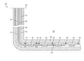
- FIG. 1 is a schematic illustration of a well system having a downhole position sensor and a service string positioned downhole, according to one aspect.
- FIG. 2 is a cross-sectional side view of part of the downhole position sensor and the service string positioned downhole from FIG. 1 , according to one aspect.
- FIG. 3 is a cross-sectional view of part of the downhole position sensor of FIG. 2 , according to one aspect.
- FIG. 5 is a cross-sectional side view of part of a downhole position sensor and a service string positioned downhole, according to another aspect.
- FIG. 6 is a cross-sectional side view of part of a downhole position sensor and a service string positioned downhole, according to another aspect.
- FIG. 7 is a cross-sectional side view of part of a wellbore assembly including a stimuli-producing device and a service string positioned downhole, according to another aspect.
- FIG. 8 is a cross-sectional side view of part of a wellbore assembly including a stimuli-producing device and a service string positioned downhole, according to another aspect.
- a service string can be positioned within the wellbore assembly and can include a stimuli-producing device.
- the downhole position sensor can include location-sensing components or sensors, such as electric gauges.
- An example of another sensor includes a fiber optic cable and an electric hall sensor.
- the sensors can be positioned along a length of the wellbore assembly.
- the wellbore assembly can be a completion assembly. The sensors can detect, in real time, the stimuli produced by the stimuli-producing device along the length of the wellbore.
- the downhole position sensor can also include a communication link that can provide communication, in real time, between the sensors and the surface of the wellbore.
- the communication link can be an electric cable.
- Another example of a communication link can be a fiber optic cable.
- the communication link can also be used for additional purposes during the life of the well or otherwise can remain within the wellbore for the life of the well.
- a fiber optic cable can monitor the temperature within the wellbore during the life of the well.
- the stimuli-producing device can include a temperature source, a vibration source, a magnet field source, a radio signal source, or other types of sources coupled to a service string.
- the service string can be a wireline, a coil tubing, a threaded tubing, a drill pipe, or other similar devices.
- the sensors can include electronic gauges coupled to an electric cable or fiber optic cable and can be mounted in screens or other downhole equipment. The sensors can communicate with surface devices using the communication link.
- the electric cable or fiber optic cable is positioned within a groove in an outer shroud of a sand control screen element.
- the electric cable or fiber optic cable is positioned beneath the filter medium of the sand control screen element.
- the electric cable or fiber optic cable can be positioned beneath a perforated pipe positioned around a tubing string of the wellbore assembly.
- the electric gauges can be positioned along an outer surface of a tubing string of the wellbore assembly or disposed partially or fully within an opening in the tubing string.
- the electric gauges can be coupled to an electric cable that provides communication between the electric gauges and the surface of the wellbore.
- the electric gauges can sense the stimuli from the service string and a signal representing the sensed stimuli can be communicated to the surface in real time.
- a fiber optic cable can be positioned along an outer surface of a tubing string of the wellbore assembly and can sense the stimuli from the service string.
- the fiber optic cable can also communicate a signal representing the sensed stimuli to the surface.
- FIG. 1 depicts a well system 100 having a wellbore assembly according to one aspect.
- the well system 100 includes a bore that is a wellbore 102 extending through a surface 104 and various earth strata.
- the wellbore 102 has a substantially vertical section 106 and a substantially horizontal section 108 .
- the substantially vertical section 106 and the substantially horizontal section 108 can include a casing string 110 cemented at an upper portion of the substantially vertical section 106 .
- the substantially horizontal section 108 extends through a hydrocarbon bearing subterranean formation 112 .
- a tubing string 114 extends from the surface within wellbore 102 .
- the tubing string 114 can be part of a completion assembly and can provide a conduit for formation fluids to travel from the substantially horizontal section 108 to the surface 104 .
- Sand control screen elements 116 are positioned at various production intervals around the tubing string 114 .
- Packers 118 can provide a fluid seal between the tubing string 114 and the wall of the wellbore 102 . Each of the packers 118 can define a production interval.
- a service string 124 is positioned within the tubing string 114 downhole in the wellbore 102 .
- the service string could be wireline, coil tubing, threaded tubing, drill pipe, or similar device.
- the service string 124 includes a stimuli-producing device 126 .
- the stimuli-producing device 126 may be a temperature source, a vibration source, a magnetic field source, a radio signal source, or another type of source.
- Electric gauges 120 are positioned on an outer surface of the tubing string 114 . In some aspects, a single electric gauge 120 can be positioned on the outer surface of the tubing string 114 rather than multiple ones.
- the electric gauges 120 are coupled to an electric cable 122 that is positioned on the outer surface of the tubing string 114 .
- the electric gauges 120 can sense the stimuli from the stimuli-producing device 126 .
- a signal representing the sensed stimuli can be communicated from the electric gauges 120 to the surface 104 by the electric cable 122 .
- Other types of communication links can be used.
- the electric cable can be replaced with a fiber optic cable, which can or cannot include electric gauges.
- FIG. 1 depicts the electric gauges 120 positioned in the substantially horizontal section 108
- the electric gauges 120 can be located, additionally or alternatively, in the substantially vertical section 106 .
- any number of the electric gauges 120 can be used in the well system 100 generally or in various intervals.
- the electric gauges 120 can be disposed in simpler wellbores, such as wellbores having only a substantially vertical section 106 .
- the electric gauges 120 can be disposed in open hole environments, such as is depicted in FIG. 1 , or in cased wells.
- the service string 124 that includes the stimuli-producing device 126 can also be disposed in simpler wellbores and in open hole environments or in cased wells.
- FIG. 2 depicts a cross-sectional side view of part of the downhole position sensor and the service string 124 positioned downhole from FIG. 1 , according to one aspect.
- the service string 124 is positioned within the tubing string 114 .
- the service string 124 includes the stimuli-producing device 126 .
- the stimuli-producing device 126 can be a temperature source.
- the temperature source can increase the surrounding temperature (e.g., the temperature source is a heat source).
- the temperature source can decrease the surrounding temperature (e.g., the temperature source is a cold source).
- the stimuli-producing device 126 can be a vibration source, a magnetic field source, or a radio signal source.
- the sand control screen elements 116 are positioned around an outer surface 128 of the tubing string 114 .
- the electric gauges 120 are positioned on the outer surface 128 of the tubing string 114 between the sand control screen elements 116 . In another aspect, the electric gauges 120 can be positioned partially or fully within an opening in the tubing string 114 .
- the electric gauges 120 can sense the stimuli produced by the stimuli-producing device 126 .
- the electric gauges 120 can sense a change in temperature caused by a temperature source, a vibration produced by a vibration source, a magnetic field produced by a magnetic field source, or a the radio signal produced by a radio signal source.
- the electric gauges 120 are coupled to the electric cable 122 .
- the electric cable 122 provides communication between the electric gauges 120 and a surface of the wellbore based on the stimuli produced by the stimuli-producing device 126 .
- the electric cable 122 is positioned on the outer surface 128 of the tubing string 114 and provides for communication between the electric gauges 120 and a surface of the wellbore.
- the electric cable 122 is positioned within a groove in an outer shroud 130 of the sand control screen elements 116 . In other aspects, the electric cable 122 can be positioned under the sand control screen elements 116 or under the outer shroud 130 , or any other suitable positions.
- the stimuli-producing device 126 can be positioned on the tubing string 114 and the electric gauges 120 and the electric cable 122 can be positioned on the service string 124 .
- the tubing string 114 can be a completion string, in one aspect.
- FIG. 3 depicts the electric cable 122 of FIG. 2 positioned within a groove 132 in the outer shroud 130 of the sand control screen element 116 .
- the electric cable 122 can be protected from damage when the tubing string 114 is inserted within a wellbore by the position of the electric cable 122 within an outer diameter of the sand control screen element 116 .
- a top surface 134 of the outer shroud 130 extends beyond the electric cable 122 and can protect the electric cable 122 during insertion into the wellbore.
- the electric cable 122 can be positioned interior to the outer shroud 130 of the sand control screen elements 116 .
- the electric cable 122 can be positioned under a perforated pipe positioned around the tubing string 114 .
- a fiber optic cable can be the communication link.
- FIG. 4 depicts a cross-sectional view of part of a downhole position sensor and a service string 202 positioned downhole, according to another aspect.
- the service string 202 is positioned within a tubing string 206 of the wellbore assembly.
- the service string 202 includes a stimuli-producing device 204 .
- the stimuli-producing device 204 is a temperature source.
- the temperature source can be a heat source.
- heat can be generated chemically, electrically (e.g., by electric heaters), by spent nuclear fuel rods, by pyrotechnic, or by other suitable heat generating means.
- the temperature source can be a cold source. In aspects in which the temperature source is a cold source, a lower temperature can be generated chemically or by other suitable means.
- the tubing string 206 has a fiber optic cable 208 positioned on an outer surface 210 of the tubing string 206 .
- the fiber optic cable 208 can extend from a surface of the wellbore along a length of the tubing string 206 .
- Sand control screen elements 212 are positioned around the outer surface 210 of the tubing string 206 .
- the sand control screen elements 212 can be positioned at various intervals along the tubing string 206 .
- the sand control screen elements 212 include an outer shroud 214 that includes a groove.
- the fiber optic cable 208 is mounted within the groove in the outer shroud 214 .
- the fiber optic cable 208 can be mounted under the outer shroud 214 .
- the fiber optic cable 208 can be mounted within the tubing string 206 .
- the fiber optic cable 208 can sense the surrounding temperature along the entire length of the fiber optic cable 208 .
- the fiber optic cable 208 can communicate to the surface of the wellbore a position along the length of the fiber optic cable where there is a change in surrounding temperature.
- the stimuli-producing device 204 can raise the temperature at a location along the tubing string 206 proximate to the stimuli-producing device 204 .
- the temperature at the sand control screen element 212 can also be increased by the stimuli-producing device 204 .
- the fiber optic cable 208 can sense an increase in the surrounding temperature at the location along the fiber optic cable 208 proximate to the sand control screen element 212 whose temperature has been raised.
- the fiber optic cable 208 can communicate to the surface of the wellbore the location along the length of the fiber optic cable 208 where the temperature increase was sensed.
- the fiber optic cable 208 can thereby indicate to the surface the location of the service string 202 .
- the stimuli-producing device 204 can be a temperature source that is a cold source.
- the fiber optic cable 208 can sense a location along the fiber optic cable 208 where the surrounding temperature has been decreased by the stimuli-producing device 204 .
- FIG. 5 is a cross-sectional side view of part of a downhole position sensor and a service string 402 positioned downhole, according to another aspect.
- the service string 402 is positioned within a tubing string 410 of a wellbore assembly.
- the service string 402 includes a stimuli-producing device 404 that is a vibration source.
- the stimuli-producing device 404 includes a set of offset weights 406 that can be spun. A vibration can be produced as the set of offset weights 406 spin.
- the stimuli-producing device 404 includes drag blocks 408 that can transmit the vibration produced by the set of offset weights 406 as they spin towards the tubing string 410 .
- the tubing string 410 includes sand control screen elements 416 positioned around an outer surface 414 of the tubing string 410 .
- the drag blocks 408 can transmit the vibration to the sand control screen element 416 proximate to the stimuli-producing device 404 .
- other suitable means can be used to produce a vibration.
- Electric gauges 412 are positioned on the outer surface 414 of the tubing string 410 between each of the sand control screen elements 416 . In other aspects, the electric gauges 412 can be positioned partially or fully within an opening in the tubing string 410 .
- the electric gauges 412 can detect a vibration transmitted to the sand control screen element 416 proximate to the stimuli-producing device 404 by the drag blocks 408 . In some aspects, the electric gauges 412 can detect the vibration transmitted by the drag blocks 408 by the use of accelerometers.
- the electric gauges 412 can sense a location range of the vibration produced by the spinning set of offset weights 406 .
- the electric gauges 412 can determine the location, relative to the tubing string 410 , where the vibration originated to a surface of the wellbore.
- the electric gauges 412 can communicate the location where the vibration originated to the surface of the wellbore via an electric cable 418 .
- the electric cable 418 can extend from the surface of the wellbore along the outer surface 414 of the tubing string 410 along a length of the tubing string 410 .
- a fiber optic cable can be used to sense the location of the vibration produced by the spinning set of offset weights 406 .
- the stimuli-producing device 404 can be an radio signal source.
- a device capable of receiving radio signals can be positioned along the length of the tubing string 410 and can detect the radio signal produced by the stimuli-producing device 404 .
- the radio signal receiving device can determine, based on the strength of the signal, the location of the source of the radio signal (i.e. the stimuli-producing device 404 ).
- the radio signal receive device can communicate to the surface of the wellbore the location of the stimuli-producing device 404 via a communication link, such as a fiber optic cable or electric cable.
- FIG. 6 depicts a cross-sectional side view of part of a downhole position sensor and a service string 502 positioned downhole, according to another aspect.
- the service string 502 is positioned within a tubing string 510 of a wellbore assembly.
- the service string 502 includes a stimuli-producing device 504 that is a magnetic field source.
- the stimuli-producing device 504 includes magnets 506 that produce a magnetic field.
- FIG. 6 shows four magnets 506 , one or more magnets can be used.
- Electric hall sensors 508 are positioned along an outer surface 512 of the tubing string 510 .
- the electric hall sensors 508 can detect the magnetic field produced by the magnets 506 .
- the electric hall sensors 508 can communicate the location of the source of the magnetic field (i.e.
- the electric cable 514 is positioned on the outer surface 512 of the tubing string 510 and is coupled to the electric hall sensors 508 .
- a plurality of sand control screen elements 516 are positioned around an outer surface of the tubing string 510 .
- the electric cable 514 is mounted within a groove in an outer shroud 518 of the sand control screen elements 516 .
- the outer shroud 518 can protect the electric cable 514 from damage during insertion into the wellbore.
- FIG. 7 depicts a cross-sectional side view of part of a wellbore assembly including stimuli-producing device 600 and a service string 602 , according to one aspect.
- the service string 602 is positioned downhole within a tubing string 604 .
- the tubing string 604 includes the stimuli-producing device 600 .
- the stimuli-producing device 600 can be a temperature source. In other aspects the stimuli-producing device 600 can be a vibration source, a magnetic field source, or a radio signal source.
- Electric gauges 606 are positioned on an outer surface 608 of the service string 602 . In another aspect, the electric gauges 606 can be positioned partially or fully within an opening in the service string 602 .
- the electric gauges 606 can sense the stimuli produced by the stimuli-producing device 600 .
- the electric gauges 606 can sense a change in temperature caused by a temperature source, a vibration produced by a vibration source, a magnetic field produced by a magnetic field source.
- a radio receiver can be used in place of the electric gauges 606 .
- the electric gauges 606 are coupled to the electric cable 610 .
- the electric cable 610 provides communication between the electric gauges 606 and a surface of the wellbore based on the stimuli produced by the stimuli-producing device 600 .
- the electric cable 610 is positioned on the outer surface 608 of the service string 602 and provides for communication between the electric gauges 606 and a surface of the wellbore. In other aspects, the electric cable 610 can be positioned partially or fully within an inner diameter of the service string 602 .
- FIG. 8 depicts a cross-sectional side view of part of a wellbore assembly including stimuli-producing device 700 and a service string 702 , according to another aspect.
- the service string 702 is positioned downhole within a tubing string 704 of a wellbore assembly.
- the wellbore assembly can be a completion assembly.
- the stimuli-producing device 700 is positioned partially within an inner diameter of the tubing string 704 .
- the stimuli-producing device 700 can be positioned fully within the inner diameter of the tubing string 704 .
- the stimuli-producing device 700 is a heat source.
- the stimuli-producing device 700 can be a cold source, a vibration source, or a magnetic field source.
- the service string 702 has a fiber optic cable 706 positioned on an outer surface 708 of the service string 702 .
- the fiber optic cable 706 can be positioned within an inner diameter of the service string 702 .
- the fiber optic cable 706 can extend along a length of the service string 702 .
- the fiber optic cable 706 can sense the surrounding temperature along the entire length of the fiber optic cable 706 .
- the fiber optic cable 706 can communicate to a surface of the wellbore a position along the length of the fiber optic cable 706 where a change in surrounding temperature occurred.
- the fiber optic cable 706 can sense where along the length of the fiber optic cable 706 the stimuli-producing device 700 caused the surrounding temperature to increase.
- the fiber optic cable 706 can send a signal to the surface of the wellbore indicating the location along the length of the fiber optic cable 706 where the temperature increase was sensed.
- a wellbore system can include a completion assembly having a completion string.
- the system can also include a service string that can be positioned within an inner diameter of the completion string.
- a location-sensing component can be positioned on the completion string or the service string.
- a communication link communicatively coupled with the location-sensing component can transmit signals representing a stimuli detected by the location-sensing component.
- a stimuli-producing device can be positioned on the other of the completion string or the service string. The stimuli-producing device can output the stimuli that is detected by the location-sensing component.
- a wellbore system can include a completion tubular and a location-sensing component.
- the location-sensing component can be positioned proximate to the completion tubular.
- the location-sensing component can detect a stimuli from a stimuli-producing device positioned on a service string.
- the service string can be positioned within an inner diameter of the completion tubular.
- the location-sensing component can also be communicatively coupled to a surface of the wellbore to communicate a signal to the surface that represents the stimuli.
- a method for determining a position of a service string within a wellbore can include producing a stimuli by a stimuli-producing device.
- the stimuli-producing device can be positioned on the service string.
- the service string can be positioned within a completion assembly.
- the method can also include sensing the stimuli by a location-sensing component located on the completion assembly.
- the location-sensing component can determine an origin location of the stimuli.
- a communication link can communicate to a surface of the wellbore the origin location of the stimuli.
Landscapes
- Engineering & Computer Science (AREA)
- Geology (AREA)
- Life Sciences & Earth Sciences (AREA)
- Mining & Mineral Resources (AREA)
- Physics & Mathematics (AREA)
- General Life Sciences & Earth Sciences (AREA)
- Fluid Mechanics (AREA)
- Environmental & Geological Engineering (AREA)
- Geochemistry & Mineralogy (AREA)
- Geophysics (AREA)
- Mechanical Engineering (AREA)
- Remote Sensing (AREA)
- Acoustics & Sound (AREA)
- Electromagnetism (AREA)
- Arrangements For Transmission Of Measured Signals (AREA)
- Sewing Machines And Sewing (AREA)
- Manufacturing Of Electrical Connectors (AREA)
- Electrical Discharge Machining, Electrochemical Machining, And Combined Machining (AREA)
Abstract
Description
Claims (14)
Applications Claiming Priority (1)
| Application Number | Priority Date | Filing Date | Title |
|---|---|---|---|
| PCT/US2013/068417 WO2015069214A1 (en) | 2013-11-05 | 2013-11-05 | Downhole position sensor |
Publications (2)
| Publication Number | Publication Date |
|---|---|
| US20160273348A1 US20160273348A1 (en) | 2016-09-22 |
| US9726004B2 true US9726004B2 (en) | 2017-08-08 |
Family
ID=53041837
Family Applications (1)
| Application Number | Title | Priority Date | Filing Date |
|---|---|---|---|
| US14/400,417 Active 2034-05-18 US9726004B2 (en) | 2013-11-05 | 2013-11-05 | Downhole position sensor |
Country Status (3)
| Country | Link |
|---|---|
| US (1) | US9726004B2 (en) |
| GB (1) | GB2535640B (en) |
| WO (1) | WO2015069214A1 (en) |
Cited By (4)
| Publication number | Priority date | Publication date | Assignee | Title |
|---|---|---|---|---|
| US20210095539A1 (en) * | 2019-09-27 | 2021-04-01 | Shane Matthews | Tubing string with agitator, tubing drift hammer tool, and related methods |
| US11118431B2 (en) | 2018-11-28 | 2021-09-14 | Chevron U.S.A. Inc. | Smart sand control service tool positioning |
| WO2022006035A1 (en) * | 2020-06-29 | 2022-01-06 | Baker Hughes Oilfield Operations Llc | Tagging assembly including a sacrificial stop component |
| US11401794B2 (en) | 2018-11-13 | 2022-08-02 | Motive Drilling Technologies, Inc. | Apparatus and methods for determining information from a well |
Families Citing this family (10)
| Publication number | Priority date | Publication date | Assignee | Title |
|---|---|---|---|---|
| SG11201502083TA (en) * | 2012-09-26 | 2015-04-29 | Halliburton Energy Services Inc | Method of placing distributed pressure gauges across screens |
| US9650889B2 (en) | 2013-12-23 | 2017-05-16 | Halliburton Energy Services, Inc. | Downhole signal repeater |
| US9784095B2 (en) | 2013-12-30 | 2017-10-10 | Halliburton Energy Services, Inc. | Position indicator through acoustics |
| WO2015112127A1 (en) | 2014-01-22 | 2015-07-30 | Halliburton Energy Services, Inc. | Remote tool position and tool status indication |
| MX2017010298A (en) * | 2015-03-17 | 2017-12-04 | Halliburton Energy Services Inc | Cementing methods and systems employing a smart plug. |
| US10533380B2 (en) | 2016-07-20 | 2020-01-14 | Halliburton Energy Services, Inc. | Downhole capacitive coupling systems |
| CN108442916B (en) * | 2017-02-10 | 2023-07-11 | 中国石油化工股份有限公司 | Open hole screen pipe damage detection tubular column for horizontal well |
| US11168561B2 (en) | 2018-01-11 | 2021-11-09 | Baker Hughes, A Ge Company, Llc | Downhole position measurement using wireless transmitters and receivers |
| US11268378B2 (en) * | 2018-02-09 | 2022-03-08 | Exxonmobil Upstream Research Company | Downhole wireless communication node and sensor/tools interface |
| WO2020086065A1 (en) * | 2018-10-23 | 2020-04-30 | Halliburton Energy Services, Inc. | Position measurement system for correlation array |
Citations (95)
| Publication number | Priority date | Publication date | Assignee | Title |
|---|---|---|---|---|
| US4945775A (en) | 1988-12-30 | 1990-08-07 | Pulsearch Consolidated Technology Ltd. | Inertial based pipeline monitoring system |
| US5275038A (en) | 1991-05-20 | 1994-01-04 | Otis Engineering Corporation | Downhole reeled tubing inspection system with fiberoptic cable |
| US5419188A (en) | 1991-05-20 | 1995-05-30 | Otis Engineering Corporation | Reeled tubing support for downhole equipment module |
| US5579842A (en) | 1995-03-17 | 1996-12-03 | Baker Hughes Integ. | Bottomhole data acquisition system for fracture/packing mechanisms |
| US5666050A (en) | 1995-11-20 | 1997-09-09 | Pes, Inc. | Downhole magnetic position sensor |
| WO1998050681A1 (en) | 1997-05-02 | 1998-11-12 | Baker Hughes Incorporated | Wellbores utilizing fiber optic-based sensors and operating devices |
| WO1998057030A1 (en) | 1997-06-09 | 1998-12-17 | Baker Hughes Incorporated | Control and monitoring system for chemical treatment of an oilfield well |
| US5925879A (en) | 1997-05-09 | 1999-07-20 | Cidra Corporation | Oil and gas well packer having fiber optic Bragg Grating sensors for downhole insitu inflation monitoring |
| US6018501A (en) | 1997-12-10 | 2000-01-25 | Halliburton Energy Services, Inc. | Subsea repeater and method for use of the same |
| US6075461A (en) | 1997-12-29 | 2000-06-13 | Halliburton Energy Services, Inc. | Disposable electromagnetic signal repeater |
| US6177882B1 (en) | 1997-12-01 | 2001-01-23 | Halliburton Energy Services, Inc. | Electromagnetic-to-acoustic and acoustic-to-electromagnetic repeaters and methods for use of same |
| EP1096271A2 (en) | 1999-10-29 | 2001-05-02 | Litton Systems, Inc. | Accoustic sensing system for downhole seismic applications utilizing an array of fibre optic sensors |
| EP1096272A2 (en) | 1999-10-29 | 2001-05-02 | Litton Systems, Inc. | Acoustic sensing system for downhole seismic applications utilizing an array of fiber optic sensors |
| EP1096273A2 (en) | 1999-10-29 | 2001-05-02 | Litton Systems, Inc. | Accoustic sensing systems for downhole seismic applications utilizing an array of fiber optic sensors |
| US6269198B1 (en) | 1999-10-29 | 2001-07-31 | Litton Systems, Inc. | Acoustic sensing system for downhole seismic applications utilizing an array of fiber optic sensors |
| US20010042617A1 (en) | 1999-09-07 | 2001-11-22 | Halliburton Energy Services, Inc. | Methods and associated apparatus for downhole data retrieval, monitoring and tool actuation |
| US20020092649A1 (en) | 2001-01-16 | 2002-07-18 | Bixenman Patrick W. | Screen and method having a partial screen wrap |
| US20020104652A1 (en) | 2000-11-03 | 2002-08-08 | Cole Jack H. | Methods of performing downhole operations using orbital vibrator energy sources |
| US6481495B1 (en) | 2000-09-25 | 2002-11-19 | Robert W. Evans | Downhole tool with electrical conductor |
| WO2003017538A1 (en) | 2001-08-20 | 2003-02-27 | Baker Hughes Incorporated | Fiber optic sensor signal amplifier |
| US20030102980A1 (en) | 2001-12-04 | 2003-06-05 | Victor Koro | Apparatus, system, and method for detecting and reimpressing electrical charge disturbances on a drill-pipe |
| US20040043501A1 (en) | 1997-05-02 | 2004-03-04 | Baker Hughes Incorporated | Monitoring of downhole parameters and chemical injection utilizing fiber optics |
| US6724319B1 (en) | 1999-10-29 | 2004-04-20 | Litton Systems, Inc. | Acoustic sensing system for downhole seismic applications utilizing an array of fiber optic sensors |
| US6728165B1 (en) | 1999-10-29 | 2004-04-27 | Litton Systems, Inc. | Acoustic sensing system for downhole seismic applications utilizing an array of fiber optic sensors |
| US20040140092A1 (en) | 2003-01-21 | 2004-07-22 | Robison Clark E. | Linear displacement measurement method and apparatus |
| US6769805B2 (en) | 1998-08-25 | 2004-08-03 | Sensor Highway Limited | Method of using a heater with a fiber optic string in a wellbore |
| US20040156265A1 (en) | 2003-02-07 | 2004-08-12 | Eric Lavrut | Pressure pulse generator for downhole tool |
| US20040163809A1 (en) | 2003-02-24 | 2004-08-26 | Mayeu Christopher W. | Method and system for determining and controlling position of valve |
| US6787758B2 (en) | 2001-02-06 | 2004-09-07 | Baker Hughes Incorporated | Wellbores utilizing fiber optic-based sensors and operating devices |
| US20040194958A1 (en) | 2003-04-07 | 2004-10-07 | Mayeu Christopher W. | Methods and systems for optical endpoint detection of a sliding sleeve valve |
| US6828547B2 (en) | 1997-05-02 | 2004-12-07 | Sensor Highway Limited | Wellbores utilizing fiber optic-based sensors and operating devices |
| US20050062979A1 (en) | 2003-09-04 | 2005-03-24 | Yizheng Zhu | Optical fiber pressure and acceleration sensor fabricated on a fiber endface |
| US6913079B2 (en) | 2000-06-29 | 2005-07-05 | Paulo S. Tubel | Method and system for monitoring smart structures utilizing distributed optical sensors |
| US6915686B2 (en) | 2003-02-11 | 2005-07-12 | Optoplan A.S. | Downhole sub for instrumentation |
| US20050263279A1 (en) | 2004-06-01 | 2005-12-01 | Baker Hughes Incorporated | Pressure monitoring of control lines for tool position feedback |
| US6978832B2 (en) | 2002-09-09 | 2005-12-27 | Halliburton Energy Services, Inc. | Downhole sensing with fiber in the formation |
| US7028543B2 (en) | 2003-01-21 | 2006-04-18 | Weatherford/Lamb, Inc. | System and method for monitoring performance of downhole equipment using fiber optic based sensors |
| US20060081413A1 (en) | 2004-10-14 | 2006-04-20 | James Minto | Wellbore signal generator |
| US20070012460A1 (en) | 2005-07-13 | 2007-01-18 | Baker Hughes Incorporated | Hydrostatic-set open hole packer with electric, hydraulic and/or optical feed throughs |
| US7201231B2 (en) | 2002-08-13 | 2007-04-10 | Reeves Wireline Technologies Limited | Apparatuses and methods for deploying logging tools and signalling in boreholes |
| US7219729B2 (en) | 2002-11-05 | 2007-05-22 | Weatherford/Lamb, Inc. | Permanent downhole deployment of optical sensors |
| US7228900B2 (en) | 2004-06-15 | 2007-06-12 | Halliburton Energy Services, Inc. | System and method for determining downhole conditions |
| US20070139217A1 (en) | 1999-02-19 | 2007-06-21 | Halliburton Energy Services, Inc., A Delaware Corp | Data relay system for casing mounted sensors, actuators and generators |
| US7240738B2 (en) | 2003-01-28 | 2007-07-10 | Baker Hughes Incorporated | Self-orienting selectable locating collet and method for location within a wellbore |
| US7245382B2 (en) | 2003-10-24 | 2007-07-17 | Optoplan As | Downhole optical sensor system with reference |
| US7254999B2 (en) | 2003-03-14 | 2007-08-14 | Weatherford/Lamb, Inc. | Permanently installed in-well fiber optic accelerometer-based seismic sensing apparatus and associated method |
| GB2436473A (en) | 2003-06-16 | 2007-09-26 | Baker Hughes Inc | A method of communicating data between a downhole device incluing a sensor system and a remote location |
| US7278480B2 (en) | 2005-03-31 | 2007-10-09 | Schlumberger Technology Corporation | Apparatus and method for sensing downhole parameters |
| US7284606B2 (en) | 2005-04-12 | 2007-10-23 | Baker Hughes Incorporated | Downhole position locating device with fluid metering feature |
| US20070285274A1 (en) | 2003-08-22 | 2007-12-13 | Schlumberger Technology Corporation | Multi-Physics Inversion Processing to Predict Pore Pressure ahead of the Drill Bit |
| US7357021B2 (en) | 2004-04-08 | 2008-04-15 | Welldynamics, Inc. | Methods of monitoring downhole conditions |
| US7417920B2 (en) | 2001-03-13 | 2008-08-26 | Baker Hughes Incorporated | Reciprocating pulser for mud pulse telemetry |
| US7436320B2 (en) | 2003-06-16 | 2008-10-14 | Baker Hughes Incorporated | Sensor system and method of communicating data between a downhole device on a remote location |
| US20080264631A1 (en) * | 2007-04-25 | 2008-10-30 | Mendez Luis E | Depth Correlation Device for Fiber Optic Line |
| US20080294344A1 (en) | 2007-05-22 | 2008-11-27 | Pathfinder Energy Services, Inc. | Angular position sensor for a downhole tool |
| US20090034368A1 (en) | 2007-08-02 | 2009-02-05 | Baker Hughes Incorporated | Apparatus and method for communicating data between a well and the surface using pressure pulses |
| US20090071645A1 (en) | 2007-09-18 | 2009-03-19 | Kenison Michael H | System and Method for Obtaining Load Measurements in a Wellbore |
| US20090128141A1 (en) | 2007-11-16 | 2009-05-21 | Hopmann Don A | Position Sensor for a Downhole Completion Device |
| US7565834B2 (en) | 2007-05-21 | 2009-07-28 | Schlumberger Technology Corporation | Methods and systems for investigating downhole conditions |
| US20090199630A1 (en) | 2008-02-12 | 2009-08-13 | Baker Hughes Incorporated | Fiber optic sensor system using white light interferometery |
| US20090201764A1 (en) | 2008-02-13 | 2009-08-13 | Baker Hughes Incorporated | Down hole mud sound speed measurement by using acoustic sensors with differentiated standoff |
| US20090301184A1 (en) | 2005-11-07 | 2009-12-10 | Halliburton Energy Services, Inc. | Apparatus for actuating a pressure delivery system of a fluid sampler |
| US20100013663A1 (en) | 2008-07-16 | 2010-01-21 | Halliburton Energy Services, Inc. | Downhole Telemetry System Using an Optically Transmissive Fluid Media and Method for Use of Same |
| US7740064B2 (en) | 2006-05-24 | 2010-06-22 | Baker Hughes Incorporated | System, method, and apparatus for downhole submersible pump having fiber optic communications |
| US20100166358A1 (en) | 2008-12-30 | 2010-07-01 | Daniel Homa | Dual Fiber Grating and Methods of Making and Using Same |
| US20100303426A1 (en) | 2009-05-29 | 2010-12-02 | Baker Hughes Incorporated | Downhole optical fiber spice housing |
| US20100309019A1 (en) | 2004-07-01 | 2010-12-09 | Halliburton Energy Services, Inc. | Acoustic telemetry transceiver |
| US7857066B2 (en) | 2005-08-03 | 2010-12-28 | Baker Hughes Incorporated | Downhole tools utilizing electroactive polymers for actuating release mechanisms |
| US7881155B2 (en) | 2006-07-26 | 2011-02-01 | Welltronics Applications LLC | Pressure release encoding system for communicating downhole information through a wellbore to a surface location |
| US7946341B2 (en) | 2007-11-02 | 2011-05-24 | Schlumberger Technology Corporation | Systems and methods for distributed interferometric acoustic monitoring |
| US20110163891A1 (en) | 2010-01-05 | 2011-07-07 | Schlumberger Technology Corporation | Methods and systems for downhole telemetry |
| US20110280105A1 (en) | 2010-05-12 | 2011-11-17 | Hall David R | Downhole Turbine Communication |
| US8109333B2 (en) | 2009-05-07 | 2012-02-07 | Baker Hughes Incorporated | Indicator and method |
| US20120037360A1 (en) | 2009-04-24 | 2012-02-16 | Arizmendi Jr Napoleon | Actuators and related methods |
| US20120046866A1 (en) | 2010-08-23 | 2012-02-23 | Schlumberger Technology Corporation | Oilfield applications for distributed vibration sensing technology |
| US20120080231A1 (en) | 2010-10-04 | 2012-04-05 | Baker Hughes Incorporated | Remotely controlled apparatus for downhole applications and related methods |
| US20120147924A1 (en) | 2010-12-08 | 2012-06-14 | Baker Hughes Incorporated | System and method for distributed environmental parameter measurement |
| US20120152562A1 (en) | 2010-12-16 | 2012-06-21 | Baker Hughes Incorporated | Apparatus and Method for Controlling Fluid Flow From a Formation |
| US20120176250A1 (en) | 2011-01-06 | 2012-07-12 | Baker Hughes Incorporated | System and method for integrated downhole sensing and optical fiber monitoring |
| US20120175135A1 (en) | 2010-03-15 | 2012-07-12 | Schlumberger Technology Corporation | Packer deployed formation sensor |
| US20120211231A1 (en) | 2010-10-18 | 2012-08-23 | Zafer Erkol | Segmented Fiber Optic Coiled Tubing Assembly |
| US20120256635A1 (en) | 2007-09-19 | 2012-10-11 | Welldynamics, Inc. | Position sensor for well tools |
| US20120286967A1 (en) | 2009-12-28 | 2012-11-15 | Laurent Alteirac | Downhole Data Transmission System |
| US20130016979A1 (en) | 2011-07-11 | 2013-01-17 | Baker Hughes Incorporated | Optical Network Configuration with Intrinsic Delay for Swept-Wavelength Interferometry Systems |
| US20130021874A1 (en) | 2008-11-06 | 2013-01-24 | Schlumberger Technology Corporation | Methods for Locating A Cement Sheath in A Cased Wellbore |
| US20130075161A1 (en) | 2011-09-26 | 2013-03-28 | Saudi Arabian Oil Company | Methods of evaluating rock properties while drilling using downhole acoustic sensors and a downhole broadband transmitting system |
| US20130087328A1 (en) | 2011-10-05 | 2013-04-11 | Halliburton Energy Services, Inc. | Downhole Species Selective Optical Fiber Sensor Systems and Methods |
| US8430163B2 (en) | 2010-03-12 | 2013-04-30 | Schlumberger Technology Corporation | Downhole acoustic sensing tool and method |
| US20140014329A1 (en) | 2012-07-10 | 2014-01-16 | Baker Hughes Incorporated | Landing indicator for logging tools |
| US20140251603A1 (en) * | 2013-03-11 | 2014-09-11 | Weatherford/Lamb, Inc. | Cement plug location |
| US20150077265A1 (en) | 2013-09-19 | 2015-03-19 | Halliburton Energy Services, Inc. | Telemetry on tubing |
| US20150167430A1 (en) | 2012-07-31 | 2015-06-18 | Petrowell Limited | Downhole apparatus and method |
| WO2015099641A1 (en) | 2013-12-23 | 2015-07-02 | Halliburton Energy Services, Inc. | Downhole signal repeater |
| WO2015102582A1 (en) | 2013-12-30 | 2015-07-09 | Halliburton Energy Services, Inc. | Position indicator through acoustics |
| WO2015112127A1 (en) | 2014-01-22 | 2015-07-30 | Halliburton Energy Services, Inc. | Remote tool position and tool status indication |
Family Cites Families (2)
| Publication number | Priority date | Publication date | Assignee | Title |
|---|---|---|---|---|
| US5828003A (en) * | 1996-01-29 | 1998-10-27 | Dowell -- A Division of Schlumberger Technology Corporation | Composite coiled tubing apparatus and methods |
| US9127531B2 (en) * | 2011-09-07 | 2015-09-08 | Halliburton Energy Services, Inc. | Optical casing collar locator systems and methods |
-
2013
- 2013-11-05 US US14/400,417 patent/US9726004B2/en active Active
- 2013-11-05 GB GB1602190.9A patent/GB2535640B/en active Active
- 2013-11-05 WO PCT/US2013/068417 patent/WO2015069214A1/en active Application Filing
Patent Citations (112)
| Publication number | Priority date | Publication date | Assignee | Title |
|---|---|---|---|---|
| US4945775B1 (en) | 1988-12-30 | 2000-05-02 | Nowsco Well Service Ltd | Inertial based pipeline monitoring system |
| US4945775A (en) | 1988-12-30 | 1990-08-07 | Pulsearch Consolidated Technology Ltd. | Inertial based pipeline monitoring system |
| US5275038A (en) | 1991-05-20 | 1994-01-04 | Otis Engineering Corporation | Downhole reeled tubing inspection system with fiberoptic cable |
| US5419188A (en) | 1991-05-20 | 1995-05-30 | Otis Engineering Corporation | Reeled tubing support for downhole equipment module |
| US5579842A (en) | 1995-03-17 | 1996-12-03 | Baker Hughes Integ. | Bottomhole data acquisition system for fracture/packing mechanisms |
| US5666050A (en) | 1995-11-20 | 1997-09-09 | Pes, Inc. | Downhole magnetic position sensor |
| US20040043501A1 (en) | 1997-05-02 | 2004-03-04 | Baker Hughes Incorporated | Monitoring of downhole parameters and chemical injection utilizing fiber optics |
| US20030205083A1 (en) | 1997-05-02 | 2003-11-06 | Baker Hughes Incorporated | Monitoring of downhole parameters and tools utilizing fiber optics |
| WO1998050681A1 (en) | 1997-05-02 | 1998-11-12 | Baker Hughes Incorporated | Wellbores utilizing fiber optic-based sensors and operating devices |
| US6828547B2 (en) | 1997-05-02 | 2004-12-07 | Sensor Highway Limited | Wellbores utilizing fiber optic-based sensors and operating devices |
| US20050012036A1 (en) | 1997-05-02 | 2005-01-20 | Tubel Paulo S. | Providing a light cell in a wellbore |
| GB2364380A (en) | 1997-05-02 | 2002-01-23 | Baker Hughes Inc | Monitoring formation parameters using downhole sensors and controlling injection |
| US6943340B2 (en) | 1997-05-02 | 2005-09-13 | Sensor Highway Limited | Method and apparatus of providing an optical fiber along a power supply line |
| US7201221B2 (en) | 1997-05-02 | 2007-04-10 | Baker Hughes Incorporated | Wellbores utilizing fiber optic-based sensors and operating devices |
| US6268911B1 (en) | 1997-05-02 | 2001-07-31 | Baker Hughes Incorporated | Monitoring of downhole parameters and tools utilizing fiber optics |
| US20090188665A1 (en) | 1997-05-02 | 2009-07-30 | Baker Hughes Incorporated | Monitoring of Downhole Parameters and Tools Utilizing Fiber Optics |
| US7040390B2 (en) | 1997-05-02 | 2006-05-09 | Baker Hughes Incorporated | Wellbores utilizing fiber optic-based sensors and operating devices |
| US5925879A (en) | 1997-05-09 | 1999-07-20 | Cidra Corporation | Oil and gas well packer having fiber optic Bragg Grating sensors for downhole insitu inflation monitoring |
| WO1998057030A1 (en) | 1997-06-09 | 1998-12-17 | Baker Hughes Incorporated | Control and monitoring system for chemical treatment of an oilfield well |
| US6177882B1 (en) | 1997-12-01 | 2001-01-23 | Halliburton Energy Services, Inc. | Electromagnetic-to-acoustic and acoustic-to-electromagnetic repeaters and methods for use of same |
| US6018501A (en) | 1997-12-10 | 2000-01-25 | Halliburton Energy Services, Inc. | Subsea repeater and method for use of the same |
| US6075461A (en) | 1997-12-29 | 2000-06-13 | Halliburton Energy Services, Inc. | Disposable electromagnetic signal repeater |
| US6769805B2 (en) | 1998-08-25 | 2004-08-03 | Sensor Highway Limited | Method of using a heater with a fiber optic string in a wellbore |
| US7932834B2 (en) | 1999-02-19 | 2011-04-26 | Halliburton Energy Services. Inc. | Data relay system for instrument and controller attached to a drill string |
| US20070139217A1 (en) | 1999-02-19 | 2007-06-21 | Halliburton Energy Services, Inc., A Delaware Corp | Data relay system for casing mounted sensors, actuators and generators |
| US20010042617A1 (en) | 1999-09-07 | 2001-11-22 | Halliburton Energy Services, Inc. | Methods and associated apparatus for downhole data retrieval, monitoring and tool actuation |
| EP1096272A2 (en) | 1999-10-29 | 2001-05-02 | Litton Systems, Inc. | Acoustic sensing system for downhole seismic applications utilizing an array of fiber optic sensors |
| US6728165B1 (en) | 1999-10-29 | 2004-04-27 | Litton Systems, Inc. | Acoustic sensing system for downhole seismic applications utilizing an array of fiber optic sensors |
| EP1096271A2 (en) | 1999-10-29 | 2001-05-02 | Litton Systems, Inc. | Accoustic sensing system for downhole seismic applications utilizing an array of fibre optic sensors |
| EP1096273A2 (en) | 1999-10-29 | 2001-05-02 | Litton Systems, Inc. | Accoustic sensing systems for downhole seismic applications utilizing an array of fiber optic sensors |
| US6269198B1 (en) | 1999-10-29 | 2001-07-31 | Litton Systems, Inc. | Acoustic sensing system for downhole seismic applications utilizing an array of fiber optic sensors |
| US6288975B1 (en) | 1999-10-29 | 2001-09-11 | Litton Systems, Inc. | Acoustic sensing system for downhole seismic applications utilizing an array of fiber optic sensors |
| US6724319B1 (en) | 1999-10-29 | 2004-04-20 | Litton Systems, Inc. | Acoustic sensing system for downhole seismic applications utilizing an array of fiber optic sensors |
| US6913079B2 (en) | 2000-06-29 | 2005-07-05 | Paulo S. Tubel | Method and system for monitoring smart structures utilizing distributed optical sensors |
| US6481495B1 (en) | 2000-09-25 | 2002-11-19 | Robert W. Evans | Downhole tool with electrical conductor |
| US20020104652A1 (en) | 2000-11-03 | 2002-08-08 | Cole Jack H. | Methods of performing downhole operations using orbital vibrator energy sources |
| US20020092649A1 (en) | 2001-01-16 | 2002-07-18 | Bixenman Patrick W. | Screen and method having a partial screen wrap |
| US6787758B2 (en) | 2001-02-06 | 2004-09-07 | Baker Hughes Incorporated | Wellbores utilizing fiber optic-based sensors and operating devices |
| US7417920B2 (en) | 2001-03-13 | 2008-08-26 | Baker Hughes Incorporated | Reciprocating pulser for mud pulse telemetry |
| WO2003017538A1 (en) | 2001-08-20 | 2003-02-27 | Baker Hughes Incorporated | Fiber optic sensor signal amplifier |
| US20030102980A1 (en) | 2001-12-04 | 2003-06-05 | Victor Koro | Apparatus, system, and method for detecting and reimpressing electrical charge disturbances on a drill-pipe |
| US7201231B2 (en) | 2002-08-13 | 2007-04-10 | Reeves Wireline Technologies Limited | Apparatuses and methods for deploying logging tools and signalling in boreholes |
| US6978832B2 (en) | 2002-09-09 | 2005-12-27 | Halliburton Energy Services, Inc. | Downhole sensing with fiber in the formation |
| US7219729B2 (en) | 2002-11-05 | 2007-05-22 | Weatherford/Lamb, Inc. | Permanent downhole deployment of optical sensors |
| US7997340B2 (en) | 2002-11-05 | 2011-08-16 | Weatherford/Lamb, Inc. | Permanent downhole deployment of optical sensors |
| US7028543B2 (en) | 2003-01-21 | 2006-04-18 | Weatherford/Lamb, Inc. | System and method for monitoring performance of downhole equipment using fiber optic based sensors |
| US20040140092A1 (en) | 2003-01-21 | 2004-07-22 | Robison Clark E. | Linear displacement measurement method and apparatus |
| US7240738B2 (en) | 2003-01-28 | 2007-07-10 | Baker Hughes Incorporated | Self-orienting selectable locating collet and method for location within a wellbore |
| US20040156265A1 (en) | 2003-02-07 | 2004-08-12 | Eric Lavrut | Pressure pulse generator for downhole tool |
| US6915686B2 (en) | 2003-02-11 | 2005-07-12 | Optoplan A.S. | Downhole sub for instrumentation |
| US20040163809A1 (en) | 2003-02-24 | 2004-08-26 | Mayeu Christopher W. | Method and system for determining and controlling position of valve |
| US7254999B2 (en) | 2003-03-14 | 2007-08-14 | Weatherford/Lamb, Inc. | Permanently installed in-well fiber optic accelerometer-based seismic sensing apparatus and associated method |
| US20100018303A1 (en) | 2003-03-14 | 2010-01-28 | Bostick Iii Francis X | Permanently installed in-well fiber optic accelerometer-based sensing apparatus and associated method |
| US7797996B2 (en) | 2003-03-14 | 2010-09-21 | Weatherford/Lamb, Inc. | Permanently installed in-well fiber optic accelerometer-based sensing apparatus and associated method |
| US20040194958A1 (en) | 2003-04-07 | 2004-10-07 | Mayeu Christopher W. | Methods and systems for optical endpoint detection of a sliding sleeve valve |
| GB2436473A (en) | 2003-06-16 | 2007-09-26 | Baker Hughes Inc | A method of communicating data between a downhole device incluing a sensor system and a remote location |
| US7982632B2 (en) | 2003-06-16 | 2011-07-19 | Baker Hughes Incorporated | Sensor system and method of communicating data between a downhole device on a remote location |
| US7436320B2 (en) | 2003-06-16 | 2008-10-14 | Baker Hughes Incorporated | Sensor system and method of communicating data between a downhole device on a remote location |
| US20070285274A1 (en) | 2003-08-22 | 2007-12-13 | Schlumberger Technology Corporation | Multi-Physics Inversion Processing to Predict Pore Pressure ahead of the Drill Bit |
| US7054011B2 (en) | 2003-09-04 | 2006-05-30 | Virginia Tech Intellectual Properties, Inc. | Optical fiber pressure and acceleration sensor fabricated on a fiber endface |
| US20050062979A1 (en) | 2003-09-04 | 2005-03-24 | Yizheng Zhu | Optical fiber pressure and acceleration sensor fabricated on a fiber endface |
| US7245382B2 (en) | 2003-10-24 | 2007-07-17 | Optoplan As | Downhole optical sensor system with reference |
| US7357021B2 (en) | 2004-04-08 | 2008-04-15 | Welldynamics, Inc. | Methods of monitoring downhole conditions |
| US20050263279A1 (en) | 2004-06-01 | 2005-12-01 | Baker Hughes Incorporated | Pressure monitoring of control lines for tool position feedback |
| US7228900B2 (en) | 2004-06-15 | 2007-06-12 | Halliburton Energy Services, Inc. | System and method for determining downhole conditions |
| US20100309019A1 (en) | 2004-07-01 | 2010-12-09 | Halliburton Energy Services, Inc. | Acoustic telemetry transceiver |
| US20060081413A1 (en) | 2004-10-14 | 2006-04-20 | James Minto | Wellbore signal generator |
| US7278480B2 (en) | 2005-03-31 | 2007-10-09 | Schlumberger Technology Corporation | Apparatus and method for sensing downhole parameters |
| US7284606B2 (en) | 2005-04-12 | 2007-10-23 | Baker Hughes Incorporated | Downhole position locating device with fluid metering feature |
| US20070012460A1 (en) | 2005-07-13 | 2007-01-18 | Baker Hughes Incorporated | Hydrostatic-set open hole packer with electric, hydraulic and/or optical feed throughs |
| US7857066B2 (en) | 2005-08-03 | 2010-12-28 | Baker Hughes Incorporated | Downhole tools utilizing electroactive polymers for actuating release mechanisms |
| US20090301184A1 (en) | 2005-11-07 | 2009-12-10 | Halliburton Energy Services, Inc. | Apparatus for actuating a pressure delivery system of a fluid sampler |
| US7740064B2 (en) | 2006-05-24 | 2010-06-22 | Baker Hughes Incorporated | System, method, and apparatus for downhole submersible pump having fiber optic communications |
| US7881155B2 (en) | 2006-07-26 | 2011-02-01 | Welltronics Applications LLC | Pressure release encoding system for communicating downhole information through a wellbore to a surface location |
| US20080264631A1 (en) * | 2007-04-25 | 2008-10-30 | Mendez Luis E | Depth Correlation Device for Fiber Optic Line |
| US7565834B2 (en) | 2007-05-21 | 2009-07-28 | Schlumberger Technology Corporation | Methods and systems for investigating downhole conditions |
| US20080294344A1 (en) | 2007-05-22 | 2008-11-27 | Pathfinder Energy Services, Inc. | Angular position sensor for a downhole tool |
| US20090034368A1 (en) | 2007-08-02 | 2009-02-05 | Baker Hughes Incorporated | Apparatus and method for communicating data between a well and the surface using pressure pulses |
| US20090071645A1 (en) | 2007-09-18 | 2009-03-19 | Kenison Michael H | System and Method for Obtaining Load Measurements in a Wellbore |
| US20120256635A1 (en) | 2007-09-19 | 2012-10-11 | Welldynamics, Inc. | Position sensor for well tools |
| US7946341B2 (en) | 2007-11-02 | 2011-05-24 | Schlumberger Technology Corporation | Systems and methods for distributed interferometric acoustic monitoring |
| US8237443B2 (en) | 2007-11-16 | 2012-08-07 | Baker Hughes Incorporated | Position sensor for a downhole completion device |
| US20090128141A1 (en) | 2007-11-16 | 2009-05-21 | Hopmann Don A | Position Sensor for a Downhole Completion Device |
| US20090199630A1 (en) | 2008-02-12 | 2009-08-13 | Baker Hughes Incorporated | Fiber optic sensor system using white light interferometery |
| US20090201764A1 (en) | 2008-02-13 | 2009-08-13 | Baker Hughes Incorporated | Down hole mud sound speed measurement by using acoustic sensors with differentiated standoff |
| US20100013663A1 (en) | 2008-07-16 | 2010-01-21 | Halliburton Energy Services, Inc. | Downhole Telemetry System Using an Optically Transmissive Fluid Media and Method for Use of Same |
| US20130021874A1 (en) | 2008-11-06 | 2013-01-24 | Schlumberger Technology Corporation | Methods for Locating A Cement Sheath in A Cased Wellbore |
| US20100166358A1 (en) | 2008-12-30 | 2010-07-01 | Daniel Homa | Dual Fiber Grating and Methods of Making and Using Same |
| US20120037360A1 (en) | 2009-04-24 | 2012-02-16 | Arizmendi Jr Napoleon | Actuators and related methods |
| US8109333B2 (en) | 2009-05-07 | 2012-02-07 | Baker Hughes Incorporated | Indicator and method |
| US20100303426A1 (en) | 2009-05-29 | 2010-12-02 | Baker Hughes Incorporated | Downhole optical fiber spice housing |
| US20120286967A1 (en) | 2009-12-28 | 2012-11-15 | Laurent Alteirac | Downhole Data Transmission System |
| US20110163891A1 (en) | 2010-01-05 | 2011-07-07 | Schlumberger Technology Corporation | Methods and systems for downhole telemetry |
| US8430163B2 (en) | 2010-03-12 | 2013-04-30 | Schlumberger Technology Corporation | Downhole acoustic sensing tool and method |
| US20120175135A1 (en) | 2010-03-15 | 2012-07-12 | Schlumberger Technology Corporation | Packer deployed formation sensor |
| US20110280105A1 (en) | 2010-05-12 | 2011-11-17 | Hall David R | Downhole Turbine Communication |
| US20120046866A1 (en) | 2010-08-23 | 2012-02-23 | Schlumberger Technology Corporation | Oilfield applications for distributed vibration sensing technology |
| US20120080231A1 (en) | 2010-10-04 | 2012-04-05 | Baker Hughes Incorporated | Remotely controlled apparatus for downhole applications and related methods |
| US20120211231A1 (en) | 2010-10-18 | 2012-08-23 | Zafer Erkol | Segmented Fiber Optic Coiled Tubing Assembly |
| US20120147924A1 (en) | 2010-12-08 | 2012-06-14 | Baker Hughes Incorporated | System and method for distributed environmental parameter measurement |
| US20120152562A1 (en) | 2010-12-16 | 2012-06-21 | Baker Hughes Incorporated | Apparatus and Method for Controlling Fluid Flow From a Formation |
| US20120176250A1 (en) | 2011-01-06 | 2012-07-12 | Baker Hughes Incorporated | System and method for integrated downhole sensing and optical fiber monitoring |
| US20130016979A1 (en) | 2011-07-11 | 2013-01-17 | Baker Hughes Incorporated | Optical Network Configuration with Intrinsic Delay for Swept-Wavelength Interferometry Systems |
| US20130075161A1 (en) | 2011-09-26 | 2013-03-28 | Saudi Arabian Oil Company | Methods of evaluating rock properties while drilling using downhole acoustic sensors and a downhole broadband transmitting system |
| US20130087328A1 (en) | 2011-10-05 | 2013-04-11 | Halliburton Energy Services, Inc. | Downhole Species Selective Optical Fiber Sensor Systems and Methods |
| US20140014329A1 (en) | 2012-07-10 | 2014-01-16 | Baker Hughes Incorporated | Landing indicator for logging tools |
| US20150167430A1 (en) | 2012-07-31 | 2015-06-18 | Petrowell Limited | Downhole apparatus and method |
| US20140251603A1 (en) * | 2013-03-11 | 2014-09-11 | Weatherford/Lamb, Inc. | Cement plug location |
| US20150077265A1 (en) | 2013-09-19 | 2015-03-19 | Halliburton Energy Services, Inc. | Telemetry on tubing |
| WO2015099641A1 (en) | 2013-12-23 | 2015-07-02 | Halliburton Energy Services, Inc. | Downhole signal repeater |
| WO2015102582A1 (en) | 2013-12-30 | 2015-07-09 | Halliburton Energy Services, Inc. | Position indicator through acoustics |
| WO2015112127A1 (en) | 2014-01-22 | 2015-07-30 | Halliburton Energy Services, Inc. | Remote tool position and tool status indication |
Non-Patent Citations (16)
| Title |
|---|
| "Acoustic Telemetry System", Halliburton Testing and Subsea, 2010, 4 pages. |
| "Bumper Spring with Collet Latch", Ferguson Bearegard, 2012, 1 page. |
| "EM Telemetry Tool for Deep Well Drilling Applications", Deep Trek Program Solicitation, E-Spectrum Technologies, Inc., 2 pages. |
| "Fiber Optic Sensing Technologies for Well Monitoring to Reservoir Management", Pinanacle, 2012, 7 Pages. |
| "Permanent Downhole Monitoring Solutions", Promore, Core Lab Reservoir Optimization www.promore.com, 2 pages. |
| "Permanent Downhole Monitoring", Weatherford, 2006, 16 pages. |
| "SureView Real-Time Fiber-Optic Compaction Monitoring System", The SureView RTCM system Baker Hughes, 2010, 4 pages. |
| Andren et al., "Integrated Ocean Drilling Program", Expedition 347 Scientific Prospectus, 61 pages. |
| Camwell et al., "Acoustic Telemetry, with Multiple Nodes in Drillstring, used to Achieve Distributed MWD", Innovating While Drilling, Mar./Apr. 2009, pp. 1-6. |
| Dria , "E&P Applications of Fiber Optic Technologies", Myden Energy Consulting PLLC, May 2012, 47 pages. |
| Fernandez et al., "Integrated drilling system using mud actuated down hole hammer as primary engine", Novatek, Report #34365R05, May 1996, 35 pages. |
| Harper et al., "Advanced Acoustic Telemetry System Provides Real-time Data Acquisition that Increases Efficiency in Well Testing Operations", Offshore Technology Conference, May 5-8, 2003, 16 pages. |
| International Patent Application No. PCT/US2013/068417, International Search Report and Written Opinion mailed Jul. 24, 2014, 17 pages. |
| Lienau, "Direct-Use Downhole Pumps", Geo-Heat Center Quarterly Bulletin vol. 8, No. 3, 1984, 7 Pages. |
| Skinner et al., "Downhole Fiber-optic Sensing: The Oilfield Service Provider's Perspective", Halliburton Energy Services, Fiber Optic Sensor Technology and Applications III, Proc. of SPIE vol. 5589, 2004, pp. 206-220. |
| Wassermann et al., "How High-Speed Telemetry Affects the Drilling Process", JPT, Jun. 2009, 4 pages. |
Cited By (5)
| Publication number | Priority date | Publication date | Assignee | Title |
|---|---|---|---|---|
| US11401794B2 (en) | 2018-11-13 | 2022-08-02 | Motive Drilling Technologies, Inc. | Apparatus and methods for determining information from a well |
| US11118431B2 (en) | 2018-11-28 | 2021-09-14 | Chevron U.S.A. Inc. | Smart sand control service tool positioning |
| US20210095539A1 (en) * | 2019-09-27 | 2021-04-01 | Shane Matthews | Tubing string with agitator, tubing drift hammer tool, and related methods |
| US11598171B2 (en) * | 2019-09-27 | 2023-03-07 | Complete Directional Services Ltd. | Tubing string with agitator, tubing drift hammer tool, and related methods |
| WO2022006035A1 (en) * | 2020-06-29 | 2022-01-06 | Baker Hughes Oilfield Operations Llc | Tagging assembly including a sacrificial stop component |
Also Published As
| Publication number | Publication date |
|---|---|
| WO2015069214A1 (en) | 2015-05-14 |
| US20160273348A1 (en) | 2016-09-22 |
| GB201602190D0 (en) | 2016-03-23 |
| GB2535640A (en) | 2016-08-24 |
| GB2535640B (en) | 2020-08-19 |
Similar Documents
| Publication | Publication Date | Title |
|---|---|---|
| US9726004B2 (en) | Downhole position sensor | |
| EP2764200B1 (en) | System for real-time monitoring and transmitting hydraulic fracture seismic events to surface using the pilot hole of the treatment well as the monitoring well | |
| EP2762672B1 (en) | Method for real-time monitoring and transmitting hydraulic fracture seismic events to surface using the pilot hole of the treatment well as the monitoring well | |
| US8910716B2 (en) | Apparatus and method for controlling fluid flow from a formation | |
| RU2562295C2 (en) | System and methods for detection and monitoring of erosion | |
| US10519761B2 (en) | System and methodology for monitoring in a borehole | |
| EP2966258B1 (en) | Depth positioning using gamma-ray correlation and downhole parameter differential | |
| US8851189B2 (en) | Single trip multi-zone completion systems and methods | |
| NO347556B1 (en) | WELLBORE SYSTEMS WITH HYDROCARBON LEAK DETECTION APPARATUS AND METHODS | |
| EP2828477B1 (en) | Method and system for alignment of a wellbore completion | |
| CA2829523C (en) | Device for measuring and transmitting downhole tension | |
| NL2019874B1 (en) | Methods and Systems for Downhole Inductive Coupling | |
| NO20181612A1 (en) | Induction transceiver with electromagnetic sensitive gap |
Legal Events
| Date | Code | Title | Description |
|---|---|---|---|
| AS | Assignment |
Owner name: HALLIBURTON ENERGY SERVICES, INC., TEXAS Free format text: ASSIGNMENT OF ASSIGNORS INTEREST;ASSIGNORS:ECHOLS, RALPH HARVEY, III;RICHARDS, WILLIAM MARK;SIGNING DATES FROM 20131106 TO 20131107;REEL/FRAME:031574/0758 |
|
| AS | Assignment |
Owner name: HALLIBURTON ENERGY SERVICES, INC., TEXAS Free format text: ASSIGNMENT OF ASSIGNORS INTEREST;ASSIGNORS:ECHOLS, RALPH HARVEY, III;RICHARDS, WILLIAM MARK;SIGNING DATES FROM 20131106 TO 20131107;REEL/FRAME:034145/0938 |
|
| FEPP | Fee payment procedure |
Free format text: PAYOR NUMBER ASSIGNED (ORIGINAL EVENT CODE: ASPN); ENTITY STATUS OF PATENT OWNER: LARGE ENTITY |
|
| STCF | Information on status: patent grant |
Free format text: PATENTED CASE |
|
| MAFP | Maintenance fee payment |
Free format text: PAYMENT OF MAINTENANCE FEE, 4TH YEAR, LARGE ENTITY (ORIGINAL EVENT CODE: M1551); ENTITY STATUS OF PATENT OWNER: LARGE ENTITY Year of fee payment: 4 |