US9660895B1 - Geolocation routing and simulation of network conditions - Google Patents
Geolocation routing and simulation of network conditions Download PDFInfo
- Publication number
- US9660895B1 US9660895B1 US14/196,734 US201414196734A US9660895B1 US 9660895 B1 US9660895 B1 US 9660895B1 US 201414196734 A US201414196734 A US 201414196734A US 9660895 B1 US9660895 B1 US 9660895B1
- Authority
- US
- United States
- Prior art keywords
- network
- network traffic
- additional
- server
- endpoint
- Prior art date
- Legal status (The legal status is an assumption and is not a legal conclusion. Google has not performed a legal analysis and makes no representation as to the accuracy of the status listed.)
- Active, expires
Links
Images


Classifications
-
- H—ELECTRICITY
- H04—ELECTRIC COMMUNICATION TECHNIQUE
- H04L—TRANSMISSION OF DIGITAL INFORMATION, e.g. TELEGRAPHIC COMMUNICATION
- H04L43/00—Arrangements for monitoring or testing data switching networks
- H04L43/50—Testing arrangements
-
- H—ELECTRICITY
- H04—ELECTRIC COMMUNICATION TECHNIQUE
- H04L—TRANSMISSION OF DIGITAL INFORMATION, e.g. TELEGRAPHIC COMMUNICATION
- H04L41/00—Arrangements for maintenance, administration or management of data switching networks, e.g. of packet switching networks
- H04L41/14—Network analysis or design
- H04L41/145—Network analysis or design involving simulating, designing, planning or modelling of a network
-
- H—ELECTRICITY
- H04—ELECTRIC COMMUNICATION TECHNIQUE
- H04L—TRANSMISSION OF DIGITAL INFORMATION, e.g. TELEGRAPHIC COMMUNICATION
- H04L43/00—Arrangements for monitoring or testing data switching networks
- H04L43/08—Monitoring or testing based on specific metrics, e.g. QoS, energy consumption or environmental parameters
-
- H—ELECTRICITY
- H04—ELECTRIC COMMUNICATION TECHNIQUE
- H04L—TRANSMISSION OF DIGITAL INFORMATION, e.g. TELEGRAPHIC COMMUNICATION
- H04L45/00—Routing or path finding of packets in data switching networks
- H04L45/12—Shortest path evaluation
- H04L45/126—Shortest path evaluation minimising geographical or physical path length
-
- H—ELECTRICITY
- H04—ELECTRIC COMMUNICATION TECHNIQUE
- H04L—TRANSMISSION OF DIGITAL INFORMATION, e.g. TELEGRAPHIC COMMUNICATION
- H04L67/00—Network arrangements or protocols for supporting network services or applications
- H04L67/50—Network services
- H04L67/52—Network services specially adapted for the location of the user terminal
-
- H—ELECTRICITY
- H04—ELECTRIC COMMUNICATION TECHNIQUE
- H04W—WIRELESS COMMUNICATION NETWORKS
- H04W40/00—Communication routing or communication path finding
- H04W40/02—Communication route or path selection, e.g. power-based or shortest path routing
- H04W40/20—Communication route or path selection, e.g. power-based or shortest path routing based on geographic position or location
-
- H04L29/06884—
-
- H04L29/08144—
-
- H—ELECTRICITY
- H04—ELECTRIC COMMUNICATION TECHNIQUE
- H04L—TRANSMISSION OF DIGITAL INFORMATION, e.g. TELEGRAPHIC COMMUNICATION
- H04L63/00—Network architectures or network communication protocols for network security
- H04L63/02—Network architectures or network communication protocols for network security for separating internal from external traffic, e.g. firewalls
- H04L63/0272—Virtual private networks
-
- H—ELECTRICITY
- H04—ELECTRIC COMMUNICATION TECHNIQUE
- H04L—TRANSMISSION OF DIGITAL INFORMATION, e.g. TELEGRAPHIC COMMUNICATION
- H04L63/00—Network architectures or network communication protocols for network security
- H04L63/10—Network architectures or network communication protocols for network security for controlling access to devices or network resources
- H04L63/107—Network architectures or network communication protocols for network security for controlling access to devices or network resources wherein the security policies are location-dependent, e.g. entities privileges depend on current location or allowing specific operations only from locally connected terminals
-
- H—ELECTRICITY
- H04—ELECTRIC COMMUNICATION TECHNIQUE
- H04L—TRANSMISSION OF DIGITAL INFORMATION, e.g. TELEGRAPHIC COMMUNICATION
- H04L63/00—Network architectures or network communication protocols for network security
- H04L63/14—Network architectures or network communication protocols for network security for detecting or protecting against malicious traffic
- H04L63/1408—Network architectures or network communication protocols for network security for detecting or protecting against malicious traffic by monitoring network traffic
-
- H—ELECTRICITY
- H04—ELECTRIC COMMUNICATION TECHNIQUE
- H04L—TRANSMISSION OF DIGITAL INFORMATION, e.g. TELEGRAPHIC COMMUNICATION
- H04L67/00—Network arrangements or protocols for supporting network services or applications
- H04L67/01—Protocols
- H04L67/10—Protocols in which an application is distributed across nodes in the network
- H04L67/1001—Protocols in which an application is distributed across nodes in the network for accessing one among a plurality of replicated servers
Definitions
- Examples of such large-scale systems include online merchants and marketplaces, internet service providers, online businesses such as photo processing services, corporate networks, cloud computing services, web-based hosting services, etc. These entities may maintain computing resources in the form of large numbers of computing devices (e.g., thousands of hosts) that are hosted in geographically diverse locations. Clients of such systems may also be located in geographically diverse locations. Additionally, clients may connect to such systems using communications media and networks with varying characteristics and conditions. Variations in network characteristics and network conditions may result in different experiences for clients.
- FIG. 1 illustrates an example system environment for geolocation routing and simulation of network conditions, according to one embodiment.
- FIG. 2 illustrates an example system environment for geolocation routing and simulation of network conditions for client devices, according to one embodiment.
- FIG. 3 illustrates an example system environment for geolocation routing and simulation of network conditions with geographical zones, according to one embodiment.
- FIG. 4 illustrates an example system environment for geolocation routing and simulation of network conditions with network address translation for packets, according to one embodiment.
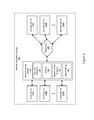
- FIG. 5 illustrates network traffic profiles for simulation of network conditions, according to one embodiment.
- FIG. 6 is a flowchart illustrating a method for performing geolocation routing and simulation of network conditions, according to one embodiment.
- FIG. 7 illustrates an example of a computing device that may be used in some embodiments.
- network connections may be simulated for clients in varying geographical locations.
- Tunneling may be used to perform geolocation routing to endpoint servers in various geographical locations so that outgoing network traffic may appear to originate from those locations.
- traffic shaping may be performed to simulate different network conditions (e.g., degraded conditions).
- customer service technicians for an online organization e.g., an online merchant
- FIG. 1 illustrates an example system environment for geolocation routing and simulation of network conditions, according to one embodiment.
- the example system environment may implement a network simulation system 100 .
- the network simulation system 100 may include at least one network access server 110 and a plurality of endpoint servers such as endpoint servers 160 A and 160 B through 160 N. Although three endpoint servers 160 A, 160 B, and 160 N are illustrated for purposes of example, it is contemplated that any suitable number and configuration of endpoint servers may be used with the network simulation system 100 .
- the network simulation system 100 may use one or more networks 180 and interconnections to couple the various components.
- Elements of the network simulation system 100 may be located in any suitable location relative to one another, from being virtual compute instances hosted on the same computing hardware to being different physical compute instances hosted in the same data center to being geographically remote.
- the endpoint servers 160 A, 160 B, and 160 N may be physically located in different geographical zones relative to one another.
- the network access server 110 may be located in the same geographical zone as one of the endpoint servers 160 A- 160 N or in a different geographical zone.
- at least some of the endpoint servers 160 A- 160 N may be owned and/or operated by the same entity that operates the network access server 110 .
- at least some of the endpoint servers 160 A- 160 N may not be owned by the same entity that operates the network access server 110 , and access to those endpoint servers may be obtained by lease or other arrangement.
- the network access server 110 may provide network access by connecting to one or more of the endpoint servers 160 A- 160 N over the network(s) 180 .
- the network access server 110 may include a plurality of components that are configured to perform aspects of providing network access.
- the network access server 110 may include endpoint selection functionality 120 , tunneling functionality 130 , and network traffic shaping functionality 140 .
- the network access server 110 may comprise one or more computing devices, any of which may be implemented by the example computing device 3000 illustrated in FIG. 7 .
- the functionality of the different services, components, and/or modules of the network access server 110 e.g., endpoint selection functionality 120 , tunneling functionality 130 , and network traffic shaping functionality 140 ) may be provided by the same computing device or by different computing devices.
- Each of the endpoint selection functionality 120 , tunneling functionality 130 , and network traffic shaping functionality 140 may represent any combination of software and hardware usable to perform their respective functions, as discussed as follows.
- the endpoint selection functionality 120 may select ones of the endpoint servers 160 A- 160 N for use in providing network access.
- An endpoint server may be selected based on any suitable combination of characteristics.
- an endpoint server may be selected based on its geographical location. In this manner, the network simulation system 100 may provide network access at endpoints in various geographical locations in order to simulate a physical presence in those geographical locations.
- an endpoint server may also be selected based on its hardware and/or software configuration, its performance metrics, its usage costs, etc.
- the tunneling functionality 130 may implement secure tunneling with one or more of the endpoint servers 160 A- 160 N (e.g., ones of the endpoint servers selected using the endpoint selection functionality 120 ). In one embodiment, the tunneling functionality 130 may use any suitable authentication and encryption techniques to ensure the security of data transmitted over a secure tunnel between the network access server 110 and one of the endpoint servers 160 A- 160 N.
- the tunnel may be established using a point-to-point connection over one or more public and/or private network(s) 180 and/or interconnections.
- the tunnel established between the network access server 110 and one of the endpoint servers 160 A- 160 N may be implemented as a secure tunnel or virtual private network (VPN) tunnel.
- VPN virtual private network
- the network traffic shaping functionality 140 may simulate different network characteristics and/or conditions.
- the network traffic shaping functionality 140 may simulate network characteristics such as latency, bandwidth caps, and packet loss. The various characteristics may be simulated for network access provided through one or more of the endpoint servers 160 A- 160 N.
- the network traffic shaping functionality 140 may use a traffic shaping component of an operating system on the network access server 110 to modify characteristics of incoming and outgoing network traffic.
- the network access server 110 may provide secure network access having simulated network conditions to an endpoint server in a particular geographical location.
- Each of the endpoint servers 160 A- 160 N may comprise one or more computing devices, any of which may be implemented by the example computing device 3000 illustrated in FIG. 7 .
- portions of the functionality of the network simulation system 100 including the network access server 110 and the endpoint servers 160 A- 160 N, may be provided by the same computing device or by any suitable number of different computing devices.
- the network access server 110 and/or endpoint servers 160 A- 160 N may be implemented as virtual compute instances or as physical compute instances.
- the virtual compute instances and/or physical compute instances may be provisioned and maintained by a provider network that manages computational resources, memory resources, storage resources, and network resources.
- a virtual compute instance may comprise one or more servers with a specified computational capacity (which may be specified by indicating the type and number of CPUs, the main memory size, and so on) and a specified software stack (e.g., a particular version of an operating system, which may in turn run on top of a hypervisor).
- a specified computational capacity which may be specified by indicating the type and number of CPUs, the main memory size, and so on
- a specified software stack e.g., a particular version of an operating system, which may in turn run on top of a hypervisor.
- One or more virtual compute instances may be implemented by the example computing device 3000 illustrated in FIG. 7 .
- a suitable component of the network simulation system 100 may select and/or provision the endpoint servers 160 A- 160 N.
- the endpoint servers 160 A- 160 N may be provisioned from a suitable pool of available computing instances.
- additional computing instances may be added to the endpoint servers 160 A- 160 N as needed.
- computing instances may be returned to the pool of available computing instances from the endpoint servers 160 A- 160 N if the computing instances are not needed at a particular point in time.
- the functionality of aspects of the network simulation system 100 may be provided to clients using a provider network.
- the functionality of the network simulation system 100 may be presented to clients as a web-accessible service.
- a network set up by an entity such as a business or a public sector organization to provide one or more services (such as various types of cloud-based computing or storage) accessible via the Internet and/or other networks to a distributed set of clients may be termed a provider network.
- a provider network may include numerous data centers hosting various resource pools, such as collections of physical and/or virtualized computer servers, storage devices, networking equipment and the like, that are used to implement and distribute the infrastructure and services offered by the provider.
- the resources may, in some embodiments, be offered to clients in units called “instances,” such as virtual or physical compute instances or storage instances.
- instances such as virtual or physical compute instances or storage instances.
- computing devices may be used singly or in combination to implement the resources of the provider network in different embodiments, including general purpose or special purpose computer servers, storage devices, network devices, and the like.
- a provider network may implement a flexible set of resource reservation, control, and access interfaces for clients.
- a provider network may implement a programmatic resource reservation interface (e.g., via a web site or a set of web pages) that allows clients to learn about, select, purchase access to, and/or reserve resources.
- the endpoint servers 160 A- 160 N may be reserved by the network access server 110 or any other suitable component using such an interface.
- the network access server 110 may use one or more suitable interfaces (such as one or more web pages, an application programming interface [API], or a command-line interface [CLI]) to reserve and configure the endpoint servers 160 A- 160 N.
- API application programming interface
- CLI command-line interface
- FIG. 2 illustrates an example system environment for geolocation routing and simulation of network conditions for client devices, according to one embodiment.
- the network access server 110 may provide secure network access having simulated network conditions to an endpoint server in a particular geographical location.
- the network access server 110 may provide such network access to one or more clients such as client devices 170 A and 170 B through 170 N.
- client devices 170 A and 170 B through 170 N may be implemented for purposes of example, it is contemplated that any suitable number of client devices may be used in conjunction with the network simulation system 100 .
- any of the client devices 170 A- 170 N may be implemented by the example computing device 3000 illustrated in FIG. 7 .
- the client devices 170 A- 170 N may typically represent mobile devices, including smartphones, tablets, etc.
- the network access server 110 may provide wired and/or wireless access to the client devices 170 A- 170 N.
- the network access server 110 may implement or include a wireless access point to allow the client devices 170 A- 170 N to connect to the wired network(s) over a wireless connection.
- the network access server 110 may manage a local wireless network which the client devices 170 A- 170 N may discover and join.
- the network access server 110 may provide network access to the endpoint servers 160 A- 160 N to client devices 170 A- 170 N that are geographically remote from the network access server 110 but connected to the network access server 110 over one or more public or private networks.
- the network access server 110 may comprise a client profiling functionality 150 .
- the client profiling functionality 150 may generate and/or maintain different network traffic shaping profiles for the client devices 170 A- 170 N.
- Each network traffic shaping profile (also referred to herein as a “network traffic profile,” a “traffic shaping profile,” or a “profile”) may describe network conditions that are sought to be simulated using the network traffic shaping functionality 140 .
- different network conditions may be simulated for different client devices.
- different network conditions may be simulated for different client devices in a simultaneous or concurrent manner.
- the client profiling functionality 150 may also maintain a geolocation selection for each of the client devices 170 A- 170 N, and the geolocation selection may be used to select one of the endpoint servers 160 A- 160 N for a particular client.
- the client profiling functionality 150 may generate and/or maintain a different profile for each of the client devices 170 A- 170 N that obtain network access through the network access server 110 .
- two or more of the client devices 170 A- 170 N may share a traffic shaping profile, e.g., if the same or similar network conditions and the same geolocation are sought to be simulated for the client devices that share the profile.
- the network access server 110 may provide network access for multiple clients at any given time, where each client has its own individual tunnel and traffic shaping profile. Further aspects of traffic shaping profiles are discussed below with reference to FIG. 5 .
- FIG. 3 illustrates an example system environment for geolocation routing and simulation of network conditions with geographical zones, according to one embodiment.
- the network simulation system 100 may provide network access at endpoint servers 160 A- 160 N in various geographical locations in order to simulate a physical presence in those geographical locations. Accordingly, individual endpoint servers 160 A, 160 B, and 160 N may be physically located in different geographical zones relative to one another. As shown in the example of FIG. 3 , the endpoint server 160 A may be located in one geographical zone 200 A, the endpoint server 160 B may be located in another geographical zone 200 B, and the endpoint server 160 N may be located in yet another geographical zone 200 N. Although three geographical zones 200 A, 200 B, and 200 N are illustrated for purposes of example, it is contemplated that any suitable number and configuration of geographical zones may be used with the network simulation system 100 .
- the geographical zones 200 A- 200 N may reflect physical areas of any suitable size, including hemispheres, time zones, continents, nations, states, districts, or other areas defined by political or geographical boundaries.
- the geographical zones 200 A- 200 N may reflect business boundaries, such as geographical zones served by different marketplaces offered by an online merchant.
- two or more of the geographical zones 200 A- 200 N may overlap at least partially.
- any of the geographical zones 200 A- 200 N may include locations that are not contiguous.
- at least some of the geographical zones 200 A- 200 N may represent the locations of endpoint servers 160 A- 160 N that are owned and/or operated by the same entity that operates the network access server 110 .
- at least some of the geographical zones 200 A- 200 N may represent the locations of endpoint servers 160 A- 160 N that are leased and not owned by the same entity that operates the network access server 110 .
- FIG. 4 illustrates an example system environment for geolocation routing and simulation of network conditions with network address translation for packets, according to one embodiment.
- network traffic originating from a client device may appear to an external server to originate from the selected endpoint server.
- a client device 170 A may specify a traffic shaping profile and a desired geolocation to the network access server 110 .
- a particular endpoint server 160 B may be selected to provide network access for the particular client device 170 A.
- the particular endpoint server 160 B may be selected for geolocation routing for each individual packet that is received by the network access server 110 from the client device 170 A.
- the client device 170 A may have one network address (e.g., IP address) 181 A
- the tunnel interface provided by the tunneling functionality 130 may have another network address (e.g., IP address) 181 B
- the selected endpoint server 160 B may have yet another network address (e.g., IP address) 181 C.
- the client device 170 A may generate network packets which are sent to the endpoint server 160 B through the tunnel.
- the client device 170 A may seek to communicate with an external server 190 , and the external server 190 may be located in a particular geographical zone 200 B.
- the external server 190 may implement a geolocation restriction such that it will acknowledge or conduct particular types of transactions only with clients within the same geographical zone 200 B (and possibly one or more additional zones).
- the external server 190 may represent an online merchant, online marketplace, or other entity that provides data to or conducts transactions with clients only in particular locales.
- the external server 190 may be determined based on the desired geolocation specified by the client device 170 A.
- the external server 190 may represent an online marketplace that serves clients in the specified geographical zone 200 B, and the external server 190 may be selected from a set of external servers that represent online marketplaces for a variety of geographical zones. Accordingly, the network simulation system 100 may perform the following operations to allow the client device 170 A to communicate with the external server 190 .
- the client device 170 A may send to the network access server 110 a packet 175 A having a source address of the client device's address 181 A and a destination address (e.g., a web address or IP address) of the external server 190 .
- the traffic shaping profile and/or the desired geographical zone 200 B may be specified by the client device 170 A using any suitable interface.
- the packet 175 A may be processed by the network traffic shaping functionality 140 , e.g., to modify the latency and/or packet loss of the traffic and/or to respect a bandwidth cap, etc.
- the endpoint server 160 B may be selected for the packet 175 A based on the desired geographical zone 200 B as well as any other desired characteristics.
- the network access server 110 may determine which routing table to use for the packet.
- each routing table has a one-to-one relationship with a tunnel interface.
- the packet may be processed using network address translation (NAT) so that the source address is changed from the address 181 A of the client device 170 A to the external address 181 B of the tunnel interface.
- NAT network address translation
- the source port of the packet may be changed to a random port.
- the mapping for the modified address and the modified source port may be stored in a table so that packets received from the endpoint server 160 B may be correctly routed back to the client device 170 A.
- the modified packet 175 B, now having a source address 181 B of the tunnel interface, may be encapsulated, encrypted, and sent to the endpoint server 160 B through the tunnel.
- the endpoint server 160 B may receive the packet 175 B, de-encapsulate it, and inspect the inner packet.
- the inner packet may include the source address 181 B and the destination address of the external server 190 .
- the source address of the packet may be changed to the address 181 C of the endpoint server 160 B, and the source port may again be randomized.
- the mapping for the newly modified address and newly modified source port may be stored in a table for the routing of packets back to the client device 170 A.
- the further modified packet 175 C may be sent to the external server 190 .
- the further modified packet 175 C may be sent over one or more public networks (e.g., the internet), and the further modified packet 175 C may not be encapsulated or encrypted.
- the external server 190 may respond to the packet, and the response may be sent back to the client device 170 A using the tunnel between the endpoint server 160 B and the network access server 110 .
- Packets sent back to the client device 170 A may be processed by the network traffic shaping functionality 140 using the traffic shaping profile associated with the client device 170 A, e.g., to modify the latency and/or packet loss of the traffic and/or to respect a bandwidth cap, etc.
- the experience of a client with an online marketplace may be simulated by a user outside the geographical scope of the marketplace.
- the user may represent a customer service technician or other employee associated with the online marketplace.
- the client device may run a test suite to gather performance metrics under the simulated network conditions.
- the network access server 110 may maintain different traffic shaping settings for individual client devices 170 A- 170 N. By simulating various network conditions for customers in various geographical areas, the customer experience on the online marketplace may be tested under the various network conditions and/or from the various geographical locations. Accordingly, the network simulation system 100 may eliminate the need to maintain whitelists of IP addresses that bypass geolocation restrictions for access to the external server 190 .
- FIG. 5 illustrates network traffic profiles for simulation of network conditions, according to one embodiment.
- the client profiling functionality 150 may generate and/or maintain different network traffic shaping profiles for the client devices 170 A- 170 N. Each profile may describe network conditions that are sought to be simulated using the network traffic shaping functionality 140 . In one embodiment, each profile may also describe a geolocation that is sought to be simulated. Using the traffic shaping profiles, different network conditions (e.g., degraded conditions) in various locations may be simulated for different client devices. Accordingly, the client profiling functionality 150 may maintain various traffic shaping profiles such as profiles 151 A and 151 B through 151 N.
- the profiles 151 A- 151 N may not have a one-to-one relationship with the client devices 170 A- 170 N.
- the client profiling functionality 150 may maintain more profiles 151 A- 151 N than there are client devices 170 A- 170 N.
- two or more of the client devices 170 A- 170 N may share one of the profiles 151 A- 151 N.
- one of the client devices 170 A- 170 N may specify the parameters associated with a profile using a suitable interface provided by the network access server 110 , and the client profiling functionality 150 may generate and maintain a profile with the specified parameters.
- the interface(s) may include an application programming interface (API) and/or a user-friendly, web-based interface.
- one of the client devices 170 A- 170 N may select from a set of predefined traffic shaping profiles using a suitable interface provided by the network access server 110 .
- the predefined traffic shaping profiles may represent particular types of networks and/or particular network conditions.
- the client profiling functionality 150 may provide predefined profiles for simulating 3G wireless networks, 4G wireless networks, Edge wireless networks, LTE wireless networks, WiFi networks, satellite-based networks, etc. Additionally, the predefined profiles may include profiles for particular types of network conditions, such as a “3G poor” profile to simulate a low-quality or degraded 3G network.
- Each of the traffic shaping profiles 151 A- 151 N may include one or more parameters describing network conditions to be simulated.
- each profile may include a latency parameter (e.g., latency parameters 152 A- 152 N) to indicate a latency metric to be simulated, a bandwidth parameter (e.g., bandwidth parameters 153 A- 153 N) to indicate a bandwidth cap to be simulated, and a packet loss parameter (e.g., packet loss parameters 154 A- 154 N) to indicate a packet loss metric to be simulated.
- a profile for simulating a satellite-based network may indicate a 5 ms latency, a 1 megabit bandwidth cap, and a 5% packet loss.
- a profile for simulating an LTE network may indicate a 100 ms latency, a 14 megabit bandwidth cap, and a 0% packet loss.
- each of the profiles 151 A- 151 N may include a desired geolocation (e.g., geolocations 155 A- 155 N) to be simulated for one or more of the client devices 170 A- 170 N.
- a desired geolocation e.g., geolocations 155 A- 155 N
- different networks or connection types may be simulated by maintaining different profiles for shaping or conditioning network traffic between a client device and a selected endpoint server.
- a client device may change its associated traffic shaping profile at any time and “on the fly.”
- a client device may request that a second set of packets be conditioned according to a second set of traffic shaping parameters after a first set of packets has already been conditioned according to a first set of traffic shaping parameters.
- Changing the traffic shaping profile for a client device may include changing the requested geolocation or maintaining the same geolocation.
- FIG. 6 is a flowchart illustrating a method for performing geolocation routing and simulation of network conditions, according to one embodiment.
- a request for traffic shaping parameters and a geolocation may be received by a network access server from a client device.
- a network traffic profile may be specified by the client device or determined for the client device based on traffic shaping parameters specified in the request.
- the profile may describe network conditions and a geolocation to simulate.
- the profile may indicate a latency for network traffic, a packet loss for network traffic, a bandwidth cap for network traffic, and/or a desired geolocation.
- the profile may represent typical conditions for a particular network or connection type, such as 3G, 4G, Edge, LTE, WiFi, satellite, etc.
- the profile may be determined by the client device specifying the profile by name (e.g., the name of the network to be simulated), by the client device supplying the specific conditions to be simulated (e.g., latency, bandwidth, and/or packet loss parameters), or by any other suitable technique.
- name e.g., the name of the network to be simulated
- specific conditions to be simulated e.g., latency, bandwidth, and/or packet loss parameters
- one or more packets may be received at the network access server from the client device.
- traffic shaping may be performed on the one or more packets based on the traffic shaping parameters in the network traffic profile associated with the client.
- performing the traffic shaping may include modifying latency characteristics for the one or more packets, enforcing a bandwidth cap, and/or dropping one or more packets based on a packet loss parameter.
- an endpoint server may be selected to provide network access for the client device.
- the endpoint server may be selected by the network access server from a pool of available endpoint servers based on the geolocation requested by the client device and the geographical location of the selected endpoint server. For example, the endpoint server may be selected because it is physically located within a particular geographical zone specified by the client device.
- network traffic (e.g., the one or more packets) may be routed from the client device to an external server through the selected endpoint server.
- the network traffic may be routed using simulated conditions based on the network traffic profile, e.g., to modify the latency and/or packet loss of the traffic and/or to respect a bandwidth cap.
- a tunnel e.g., a VPN tunnel or other secure tunnel
- the traffic received at the external server may appear to originate from the selected endpoint server rather than from the client device or network access server. In this manner, a geolocation restriction enforced by the external server may be bypassed.
- a computer system that implements a portion or all of one or more of the technologies described herein may include a general-purpose computer system that includes or is configured to access one or more computer-readable media.
- FIG. 7 illustrates such a general-purpose computing device 3000 .
- computing device 3000 includes one or more processors 3010 a - 3010 n coupled to a system memory 3020 via an input/output (I/O) interface 3030 .
- Computing device 3000 further includes a network interface 3040 coupled to I/O interface 3030 .
- computing device 3000 may be a uniprocessor system including one processor or a multiprocessor system including several processors 3010 a and 3010 b through 3010 n (e.g., two, four, eight, or another suitable number), referred to collectively as processors 3010 .
- Processors 3010 may include any suitable processors capable of executing instructions.
- processors 3010 may be general-purpose or embedded processors implementing any of a variety of instruction set architectures (ISAs), such as the x86, PowerPC, SPARC, or MIPS ISAs, or any other suitable ISA.
- ISAs instruction set architectures
- each of processors 3010 may commonly, but not necessarily, implement the same ISA.
- System memory 3020 may be configured to store program instructions and data accessible by processor(s) 3010 .
- system memory 3020 may be implemented using any suitable memory technology, such as static random access memory (SRAM), synchronous dynamic RAM (SDRAM), nonvolatile/Flash-type memory, or any other type of memory.
- SRAM static random access memory
- SDRAM synchronous dynamic RAM
- program instructions and data implementing one or more desired functions are shown stored within system memory 3020 as code (i.e., program instructions) 3025 and data 3026 .
- I/O interface 3030 may be configured to coordinate I/O traffic between processor 3010 , system memory 3020 , and any peripheral devices in the device, including network interface 3040 or other peripheral interfaces.
- I/O interface 3030 may perform any necessary protocol, timing or other data transformations to convert data signals from one component (e.g., system memory 3020 ) into a format suitable for use by another component (e.g., processor 3010 ).
- I/O interface 3030 may include support for devices attached through various types of peripheral buses, such as a variant of the Peripheral Component Interconnect (PCI) bus standard or the Universal Serial Bus (USB) standard, for example.
- PCI Peripheral Component Interconnect
- USB Universal Serial Bus
- I/O interface 3030 may be split into two or more separate components, such as a north bridge and a south bridge, for example. Also, in some embodiments some or all of the functionality of I/O interface 3030 , such as an interface to system memory 3020 , may be incorporated directly into processor 3010 .
- Network interface 3040 may be configured to allow data to be exchanged between computing device 3000 and other devices 3060 attached to a network or networks 3050 , such as other computer systems or devices, for example.
- network interface 3040 may support communication via any suitable wired or wireless general data networks, such as types of Ethernet network, for example.
- network interface 3040 may support communication via telecommunications/telephony networks such as analog voice networks or digital fiber communications networks, via storage area networks such as Fibre Channel SANs, or via any other suitable type of network and/or protocol.
- system memory 3020 may be one embodiment of a computer-readable (i.e., computer-accessible) medium configured to store program instructions and data as described above for implementing embodiments of the corresponding methods and apparatus.
- program instructions and/or data may be received, sent or stored upon different types of computer-readable media.
- a computer-readable medium may include non-transitory storage media or memory media such as magnetic or optical media, e.g., disk or DVD/CD coupled to computing device 3000 via I/O interface 3030 .
- a non-transitory computer-readable storage medium may also include any volatile or non-volatile media such as RAM (e.g.
- a computer-readable medium may include transmission media or signals such as electrical, electromagnetic, or digital signals, conveyed via a communication medium such as a network and/or a wireless link, such as may be implemented via network interface 3040 .
- a communication medium such as a network and/or a wireless link, such as may be implemented via network interface 3040 .
- Portions or all of multiple computing devices such as that illustrated in FIG. 7 may be used to implement the described functionality in various embodiments; for example, software components running on a variety of different devices and servers may collaborate to provide the functionality.
- portions of the described functionality may be implemented using storage devices, network devices, or special-purpose computer systems, in addition to or instead of being implemented using general-purpose computer systems.
- the term “computing device,” as used herein, refers to at least all these types of devices, and is not limited to these types of devices.
- a computer-readable medium may include storage media or memory media such as magnetic or optical media, e.g., disk or DVD/CD-ROM, volatile or non-volatile media such as RAM (e.g. SDRAM, DDR, RDRAM, SRAM, etc.), ROM, etc.
- a computer-readable medium may also include transmission media or signals such as electrical, electromagnetic, or digital signals, conveyed via a communication medium such as network and/or a wireless link.
- the various methods as illustrated in the Figures and described herein represent exemplary embodiments of methods.
- the methods may be implemented in software, hardware, or a combination thereof.
- the order of the steps may be changed, and various elements may be added, reordered, combined, omitted, modified, etc.
- Various of the steps may be performed automatically (e.g., without being directly prompted by user input) and/or programmatically (e.g., according to program instructions).
Abstract
Methods and systems for geolocation routing and simulation of network conditions are disclosed. A network traffic profile is determined for a client device. A network access server selects an endpoint server based on the location of the selected endpoint server. The network access server routes traffic from the client device to an external server through the selected endpoint server. The network traffic from the client device to the external server appears to originate from a network address of the selected endpoint server. Network conditions for the network traffic are simulated based on the network traffic profile.
Description
Many companies and other organizations operate computer networks that interconnect numerous computing systems to support their operations, such as with the computing systems being co-located or instead located in multiple distinct geographical locations (e.g., connected via one or more private or public intermediate networks). For example, data centers housing significant numbers of interconnected computing systems have become commonplace, such as private data centers that are operated by and on behalf of a single organization and public data centers that are operated by entities as businesses to provide computing resources to customers. Some public data center operators provide network access, power, and secure installation facilities for hardware owned by various customers, while other public data center operators provide “full service” facilities that also include hardware resources made available for use by their customers. As the scale and scope of typical data centers has increased, the tasks of provisioning, administering, and managing the computing resources have become increasingly complicated.
Examples of such large-scale systems include online merchants and marketplaces, internet service providers, online businesses such as photo processing services, corporate networks, cloud computing services, web-based hosting services, etc. These entities may maintain computing resources in the form of large numbers of computing devices (e.g., thousands of hosts) that are hosted in geographically diverse locations. Clients of such systems may also be located in geographically diverse locations. Additionally, clients may connect to such systems using communications media and networks with varying characteristics and conditions. Variations in network characteristics and network conditions may result in different experiences for clients.
While embodiments are described herein by way of example for several embodiments and illustrative drawings, those skilled in the art will recognize that embodiments are not limited to the embodiments or drawings described. It should be understood, that the drawings and detailed description thereto are not intended to limit embodiments to the particular form disclosed, but on the contrary, the intention is to cover all modifications, equivalents and alternatives falling within the spirit and scope as defined by the appended claims. The headings used herein are for organizational purposes only and are not meant to be used to limit the scope of the description or the claims. As used throughout this application, the word “may” is used in a permissive sense (i.e., meaning “having the potential to”), rather than the mandatory sense (i.e., meaning “must”). Similarly, the words “include,” “including,” and “includes” mean “including, but not limited to.”
Various embodiments of methods and systems for performing geolocation routing and simulation of network conditions are described. Using the methods and systems as described herein, network connections may be simulated for clients in varying geographical locations. Tunneling may be used to perform geolocation routing to endpoint servers in various geographical locations so that outgoing network traffic may appear to originate from those locations. Additionally, traffic shaping may be performed to simulate different network conditions (e.g., degraded conditions). In this manner, customer service technicians for an online organization (e.g., an online merchant) may simulate the experiences of customers in various locations.
In various embodiments, the network access server 110 may provide network access by connecting to one or more of the endpoint servers 160A-160N over the network(s) 180. The network access server 110 may include a plurality of components that are configured to perform aspects of providing network access. For example, the network access server 110 may include endpoint selection functionality 120, tunneling functionality 130, and network traffic shaping functionality 140. The network access server 110 may comprise one or more computing devices, any of which may be implemented by the example computing device 3000 illustrated in FIG. 7 . In various embodiments, the functionality of the different services, components, and/or modules of the network access server 110 (e.g., endpoint selection functionality 120, tunneling functionality 130, and network traffic shaping functionality 140) may be provided by the same computing device or by different computing devices. If any of the various components are implemented using different computing devices, then the respective computing devices may be communicatively coupled, e.g., via a network. Each of the endpoint selection functionality 120, tunneling functionality 130, and network traffic shaping functionality 140 may represent any combination of software and hardware usable to perform their respective functions, as discussed as follows.
In one embodiment, the endpoint selection functionality 120 may select ones of the endpoint servers 160A-160N for use in providing network access. An endpoint server may be selected based on any suitable combination of characteristics. In one embodiment, an endpoint server may be selected based on its geographical location. In this manner, the network simulation system 100 may provide network access at endpoints in various geographical locations in order to simulate a physical presence in those geographical locations. In one embodiment, an endpoint server may also be selected based on its hardware and/or software configuration, its performance metrics, its usage costs, etc.
In one embodiment, the tunneling functionality 130 may implement secure tunneling with one or more of the endpoint servers 160A-160N (e.g., ones of the endpoint servers selected using the endpoint selection functionality 120). In one embodiment, the tunneling functionality 130 may use any suitable authentication and encryption techniques to ensure the security of data transmitted over a secure tunnel between the network access server 110 and one of the endpoint servers 160A-160N. The tunnel may be established using a point-to-point connection over one or more public and/or private network(s) 180 and/or interconnections. In one embodiment, the tunnel established between the network access server 110 and one of the endpoint servers 160A-160N may be implemented as a secure tunnel or virtual private network (VPN) tunnel.
In one embodiment, the network traffic shaping functionality 140 may simulate different network characteristics and/or conditions. For example, the network traffic shaping functionality 140 may simulate network characteristics such as latency, bandwidth caps, and packet loss. The various characteristics may be simulated for network access provided through one or more of the endpoint servers 160A-160N. In one embodiment, the network traffic shaping functionality 140 may use a traffic shaping component of an operating system on the network access server 110 to modify characteristics of incoming and outgoing network traffic. Using the endpoint selection functionality 120, tunneling functionality 130, and network traffic shaping functionality 140, the network access server 110 may provide secure network access having simulated network conditions to an endpoint server in a particular geographical location.
Each of the endpoint servers 160A-160N may comprise one or more computing devices, any of which may be implemented by the example computing device 3000 illustrated in FIG. 7 . In various embodiments, portions of the functionality of the network simulation system 100, including the network access server 110 and the endpoint servers 160A-160N, may be provided by the same computing device or by any suitable number of different computing devices. In some embodiments, the network access server 110 and/or endpoint servers 160A-160N may be implemented as virtual compute instances or as physical compute instances. The virtual compute instances and/or physical compute instances may be provisioned and maintained by a provider network that manages computational resources, memory resources, storage resources, and network resources. A virtual compute instance may comprise one or more servers with a specified computational capacity (which may be specified by indicating the type and number of CPUs, the main memory size, and so on) and a specified software stack (e.g., a particular version of an operating system, which may in turn run on top of a hypervisor). One or more virtual compute instances may be implemented by the example computing device 3000 illustrated in FIG. 7 .
In one embodiment, a suitable component of the network simulation system 100 may select and/or provision the endpoint servers 160A-160N. For example, the endpoint servers 160A-160N may be provisioned from a suitable pool of available computing instances. In one embodiment, additional computing instances may be added to the endpoint servers 160A-160N as needed. In one embodiment, computing instances may be returned to the pool of available computing instances from the endpoint servers 160A-160N if the computing instances are not needed at a particular point in time.
In one embodiment, the functionality of aspects of the network simulation system 100, including the network access server 110 and/or endpoint servers 160A-160N, may be provided to clients using a provider network. For example, the functionality of the network simulation system 100 may be presented to clients as a web-accessible service. A network set up by an entity such as a business or a public sector organization to provide one or more services (such as various types of cloud-based computing or storage) accessible via the Internet and/or other networks to a distributed set of clients may be termed a provider network. A provider network may include numerous data centers hosting various resource pools, such as collections of physical and/or virtualized computer servers, storage devices, networking equipment and the like, that are used to implement and distribute the infrastructure and services offered by the provider. The resources may, in some embodiments, be offered to clients in units called “instances,” such as virtual or physical compute instances or storage instances. A number of different types of computing devices may be used singly or in combination to implement the resources of the provider network in different embodiments, including general purpose or special purpose computer servers, storage devices, network devices, and the like.
In one embodiment, a provider network may implement a flexible set of resource reservation, control, and access interfaces for clients. For example, a provider network may implement a programmatic resource reservation interface (e.g., via a web site or a set of web pages) that allows clients to learn about, select, purchase access to, and/or reserve resources. In one embodiment, the endpoint servers 160A-160N may be reserved by the network access server 110 or any other suitable component using such an interface. In one embodiment, the network access server 110 may use one or more suitable interfaces (such as one or more web pages, an application programming interface [API], or a command-line interface [CLI]) to reserve and configure the endpoint servers 160A-160N.
In various embodiments, the network access server 110 may provide wired and/or wireless access to the client devices 170A-170N. In one embodiment, for example, the network access server 110 may implement or include a wireless access point to allow the client devices 170A-170N to connect to the wired network(s) over a wireless connection. Accordingly, the network access server 110 may manage a local wireless network which the client devices 170A-170N may discover and join. In one embodiment, the network access server 110 may provide network access to the endpoint servers 160A-160N to client devices 170A-170N that are geographically remote from the network access server 110 but connected to the network access server 110 over one or more public or private networks.
In one embodiment, the network access server 110 may comprise a client profiling functionality 150. The client profiling functionality 150 may generate and/or maintain different network traffic shaping profiles for the client devices 170A-170N. Each network traffic shaping profile (also referred to herein as a “network traffic profile,” a “traffic shaping profile,” or a “profile”) may describe network conditions that are sought to be simulated using the network traffic shaping functionality 140. Using the traffic shaping profiles, different network conditions may be simulated for different client devices. In one embodiment, different network conditions may be simulated for different client devices in a simultaneous or concurrent manner. The client profiling functionality 150 may also maintain a geolocation selection for each of the client devices 170A-170N, and the geolocation selection may be used to select one of the endpoint servers 160A-160N for a particular client. In one embodiment, the client profiling functionality 150 may generate and/or maintain a different profile for each of the client devices 170A-170N that obtain network access through the network access server 110. In one embodiment, two or more of the client devices 170A-170N may share a traffic shaping profile, e.g., if the same or similar network conditions and the same geolocation are sought to be simulated for the client devices that share the profile. Using the client profiling functionality 150 and the tunneling functionality 130, the network access server 110 may provide network access for multiple clients at any given time, where each client has its own individual tunnel and traffic shaping profile. Further aspects of traffic shaping profiles are discussed below with reference to FIG. 5 .
The geographical zones 200A-200N may reflect physical areas of any suitable size, including hemispheres, time zones, continents, nations, states, districts, or other areas defined by political or geographical boundaries. In one embodiment, the geographical zones 200A-200N may reflect business boundaries, such as geographical zones served by different marketplaces offered by an online merchant. In one embodiment, two or more of the geographical zones 200A-200N may overlap at least partially. In one embodiment, any of the geographical zones 200A-200N may include locations that are not contiguous. In one embodiment, at least some of the geographical zones 200A-200N may represent the locations of endpoint servers 160A-160N that are owned and/or operated by the same entity that operates the network access server 110. In one embodiment, at least some of the geographical zones 200A-200N may represent the locations of endpoint servers 160A-160N that are leased and not owned by the same entity that operates the network access server 110.
The client device 170A may seek to communicate with an external server 190, and the external server 190 may be located in a particular geographical zone 200B. In one embodiment, the external server 190 may implement a geolocation restriction such that it will acknowledge or conduct particular types of transactions only with clients within the same geographical zone 200B (and possibly one or more additional zones). For example, the external server 190 may represent an online merchant, online marketplace, or other entity that provides data to or conducts transactions with clients only in particular locales. In one embodiment, the external server 190 may be determined based on the desired geolocation specified by the client device 170A. For example, the external server 190 may represent an online marketplace that serves clients in the specified geographical zone 200B, and the external server 190 may be selected from a set of external servers that represent online marketplaces for a variety of geographical zones. Accordingly, the network simulation system 100 may perform the following operations to allow the client device 170A to communicate with the external server 190.
In one embodiment, the client device 170A may send to the network access server 110 a packet 175A having a source address of the client device's address 181A and a destination address (e.g., a web address or IP address) of the external server 190. In one embodiment, the traffic shaping profile and/or the desired geographical zone 200B may be specified by the client device 170A using any suitable interface. Using the traffic shaping profile associated with the client device 170A, the packet 175A may be processed by the network traffic shaping functionality 140, e.g., to modify the latency and/or packet loss of the traffic and/or to respect a bandwidth cap, etc. The endpoint server 160B may be selected for the packet 175A based on the desired geographical zone 200B as well as any other desired characteristics. When the packet is ready to be transmitted over the network(s) 180 to the endpoint server 160B, the network access server 110 may determine which routing table to use for the packet. In one embodiment, each routing table has a one-to-one relationship with a tunnel interface. The packet may be processed using network address translation (NAT) so that the source address is changed from the address 181A of the client device 170A to the external address 181B of the tunnel interface. In one embodiment, the source port of the packet may be changed to a random port. The mapping for the modified address and the modified source port may be stored in a table so that packets received from the endpoint server 160B may be correctly routed back to the client device 170A. The modified packet 175B, now having a source address 181B of the tunnel interface, may be encapsulated, encrypted, and sent to the endpoint server 160B through the tunnel.
The endpoint server 160B may receive the packet 175B, de-encapsulate it, and inspect the inner packet. The inner packet may include the source address 181B and the destination address of the external server 190. Using network address translation on the endpoint server 160B, the source address of the packet may be changed to the address 181C of the endpoint server 160B, and the source port may again be randomized. The mapping for the newly modified address and newly modified source port may be stored in a table for the routing of packets back to the client device 170A. The further modified packet 175C may be sent to the external server 190. The further modified packet 175C may be sent over one or more public networks (e.g., the internet), and the further modified packet 175C may not be encapsulated or encrypted. The external server 190 may respond to the packet, and the response may be sent back to the client device 170A using the tunnel between the endpoint server 160B and the network access server 110. Packets sent back to the client device 170A may be processed by the network traffic shaping functionality 140 using the traffic shaping profile associated with the client device 170A, e.g., to modify the latency and/or packet loss of the traffic and/or to respect a bandwidth cap, etc.
In this manner, the experience of a client with an online marketplace (or other suitable server) may be simulated by a user outside the geographical scope of the marketplace. The user may represent a customer service technician or other employee associated with the online marketplace. The client device may run a test suite to gather performance metrics under the simulated network conditions. The network access server 110 may maintain different traffic shaping settings for individual client devices 170A-170N. By simulating various network conditions for customers in various geographical areas, the customer experience on the online marketplace may be tested under the various network conditions and/or from the various geographical locations. Accordingly, the network simulation system 100 may eliminate the need to maintain whitelists of IP addresses that bypass geolocation restrictions for access to the external server 190.
In one embodiment, one of the client devices 170A-170N may specify the parameters associated with a profile using a suitable interface provided by the network access server 110, and the client profiling functionality 150 may generate and maintain a profile with the specified parameters. The interface(s) may include an application programming interface (API) and/or a user-friendly, web-based interface. In one embodiment, one of the client devices 170A-170N may select from a set of predefined traffic shaping profiles using a suitable interface provided by the network access server 110. The predefined traffic shaping profiles may represent particular types of networks and/or particular network conditions. For example, the client profiling functionality 150 may provide predefined profiles for simulating 3G wireless networks, 4G wireless networks, Edge wireless networks, LTE wireless networks, WiFi networks, satellite-based networks, etc. Additionally, the predefined profiles may include profiles for particular types of network conditions, such as a “3G poor” profile to simulate a low-quality or degraded 3G network.
Each of the traffic shaping profiles 151A-151N may include one or more parameters describing network conditions to be simulated. In one embodiment, each profile may include a latency parameter (e.g., latency parameters 152A-152N) to indicate a latency metric to be simulated, a bandwidth parameter (e.g., bandwidth parameters 153A-153N) to indicate a bandwidth cap to be simulated, and a packet loss parameter (e.g., packet loss parameters 154A-154N) to indicate a packet loss metric to be simulated. For example, a profile for simulating a satellite-based network may indicate a 5 ms latency, a 1 megabit bandwidth cap, and a 5% packet loss. As another example, a profile for simulating an LTE network may indicate a 100 ms latency, a 14 megabit bandwidth cap, and a 0% packet loss. In one embodiment, each of the profiles 151A-151N may include a desired geolocation (e.g., geolocations 155A-155N) to be simulated for one or more of the client devices 170A-170N. In this manner, different networks or connection types may be simulated by maintaining different profiles for shaping or conditioning network traffic between a client device and a selected endpoint server.
In one embodiment, a client device may change its associated traffic shaping profile at any time and “on the fly.” In other words, a client device may request that a second set of packets be conditioned according to a second set of traffic shaping parameters after a first set of packets has already been conditioned according to a first set of traffic shaping parameters. Changing the traffic shaping profile for a client device may include changing the requested geolocation or maintaining the same geolocation.
As shown in 605, one or more packets may be received at the network access server from the client device. As shown in 610, traffic shaping may be performed on the one or more packets based on the traffic shaping parameters in the network traffic profile associated with the client. In one embodiment, performing the traffic shaping may include modifying latency characteristics for the one or more packets, enforcing a bandwidth cap, and/or dropping one or more packets based on a packet loss parameter.
As shown in 615, an endpoint server may be selected to provide network access for the client device. The endpoint server may be selected by the network access server from a pool of available endpoint servers based on the geolocation requested by the client device and the geographical location of the selected endpoint server. For example, the endpoint server may be selected because it is physically located within a particular geographical zone specified by the client device.
As shown in 620, network traffic (e.g., the one or more packets) may be routed from the client device to an external server through the selected endpoint server. As discussed above with respect to 610, the network traffic may be routed using simulated conditions based on the network traffic profile, e.g., to modify the latency and/or packet loss of the traffic and/or to respect a bandwidth cap. A tunnel (e.g., a VPN tunnel or other secure tunnel) may be used to send the network traffic from the network access server to the selected endpoint server. Using tunneling and network address translation, the traffic received at the external server may appear to originate from the selected endpoint server rather than from the client device or network access server. In this manner, a geolocation restriction enforced by the external server may be bypassed.
Illustrative Computer System
In at least some embodiments, a computer system that implements a portion or all of one or more of the technologies described herein may include a general-purpose computer system that includes or is configured to access one or more computer-readable media. FIG. 7 illustrates such a general-purpose computing device 3000. In the illustrated embodiment, computing device 3000 includes one or more processors 3010 a-3010 n coupled to a system memory 3020 via an input/output (I/O) interface 3030. Computing device 3000 further includes a network interface 3040 coupled to I/O interface 3030.
In various embodiments, computing device 3000 may be a uniprocessor system including one processor or a multiprocessor system including several processors 3010 a and 3010 b through 3010 n (e.g., two, four, eight, or another suitable number), referred to collectively as processors 3010. Processors 3010 may include any suitable processors capable of executing instructions. For example, in various embodiments, processors 3010 may be general-purpose or embedded processors implementing any of a variety of instruction set architectures (ISAs), such as the x86, PowerPC, SPARC, or MIPS ISAs, or any other suitable ISA. In multiprocessor systems, each of processors 3010 may commonly, but not necessarily, implement the same ISA.
In one embodiment, I/O interface 3030 may be configured to coordinate I/O traffic between processor 3010, system memory 3020, and any peripheral devices in the device, including network interface 3040 or other peripheral interfaces. In some embodiments, I/O interface 3030 may perform any necessary protocol, timing or other data transformations to convert data signals from one component (e.g., system memory 3020) into a format suitable for use by another component (e.g., processor 3010). In some embodiments, I/O interface 3030 may include support for devices attached through various types of peripheral buses, such as a variant of the Peripheral Component Interconnect (PCI) bus standard or the Universal Serial Bus (USB) standard, for example. In some embodiments, the function of I/O interface 3030 may be split into two or more separate components, such as a north bridge and a south bridge, for example. Also, in some embodiments some or all of the functionality of I/O interface 3030, such as an interface to system memory 3020, may be incorporated directly into processor 3010.
In some embodiments, system memory 3020 may be one embodiment of a computer-readable (i.e., computer-accessible) medium configured to store program instructions and data as described above for implementing embodiments of the corresponding methods and apparatus. However, in other embodiments, program instructions and/or data may be received, sent or stored upon different types of computer-readable media. Generally speaking, a computer-readable medium may include non-transitory storage media or memory media such as magnetic or optical media, e.g., disk or DVD/CD coupled to computing device 3000 via I/O interface 3030. A non-transitory computer-readable storage medium may also include any volatile or non-volatile media such as RAM (e.g. SDRAM, DDR SDRAM, RDRAM, SRAM, etc.), ROM, etc, that may be included in some embodiments of computing device 3000 as system memory 3020 or another type of memory. Further, a computer-readable medium may include transmission media or signals such as electrical, electromagnetic, or digital signals, conveyed via a communication medium such as a network and/or a wireless link, such as may be implemented via network interface 3040. Portions or all of multiple computing devices such as that illustrated in FIG. 7 may be used to implement the described functionality in various embodiments; for example, software components running on a variety of different devices and servers may collaborate to provide the functionality. In some embodiments, portions of the described functionality may be implemented using storage devices, network devices, or special-purpose computer systems, in addition to or instead of being implemented using general-purpose computer systems. The term “computing device,” as used herein, refers to at least all these types of devices, and is not limited to these types of devices.
Various embodiments may further include receiving, sending, or storing instructions and/or data implemented in accordance with the foregoing description upon a computer-readable medium. Generally speaking, a computer-readable medium may include storage media or memory media such as magnetic or optical media, e.g., disk or DVD/CD-ROM, volatile or non-volatile media such as RAM (e.g. SDRAM, DDR, RDRAM, SRAM, etc.), ROM, etc. In some embodiments, a computer-readable medium may also include transmission media or signals such as electrical, electromagnetic, or digital signals, conveyed via a communication medium such as network and/or a wireless link.
The various methods as illustrated in the Figures and described herein represent exemplary embodiments of methods. The methods may be implemented in software, hardware, or a combination thereof. In various of the methods, the order of the steps may be changed, and various elements may be added, reordered, combined, omitted, modified, etc. Various of the steps may be performed automatically (e.g., without being directly prompted by user input) and/or programmatically (e.g., according to program instructions).
Various modifications and changes may be made as would be obvious to a person skilled in the art having the benefit of this disclosure. It is intended to embrace all such modifications and changes and, accordingly, the above description is to be regarded in an illustrative rather than a restrictive sense.
Claims (20)
1. A system, comprising:
a plurality of computing devices, each comprising at least one processor coupled to a respective memory, wherein the plurality of computing devices are configured to implement a network simulation system comprising a network access server and a plurality of endpoint servers, and wherein the network access server is configured to:
determine a network traffic profile for a client device seeking network access through the network access server, wherein the network traffic profile comprises one or more of a network latency parameter, a network bandwidth parameter, or a network packet loss parameter;
select an individual endpoint server from the plurality of endpoint servers based on a geographical location of the selected endpoint server;
route network traffic from the client device to an external server through the selected endpoint server, wherein the network traffic sent from the client device to the external server appears to originate from a network address of the selected endpoint server; and
simulate network conditions for the network traffic based on the network traffic profile.
2. The system as recited in claim 1 , wherein the network access server is configured to:
create a tunnel between the network access server and the selected endpoint server, wherein the network traffic from the client device to the external server is routed through the tunnel using network address translation.
3. The system as recited in claim 1 , wherein, in simulating the network conditions for the network traffic based on the network traffic profile, the network access server is configured to:
simulate degraded network conditions for the network traffic based on the network traffic profile.
4. The system as recited in claim 1 , wherein the network access server is configured to:
determine an additional network traffic profile for an additional client device seeking network access through the network access server, wherein the additional network traffic profile comprises one or more of an additional network latency configuration, an additional network bandwidth configuration, or an additional network packet loss configuration;
select an additional individual endpoint server from the plurality of endpoint servers based on a geographical location of the selected additional endpoint server;
route additional network traffic from the additional client device to an additional external server through the selected additional endpoint server, wherein the additional network traffic sent from the additional client device to the additional external server appears to originate from a network address of the selected additional endpoint server; and
simulate network conditions for the additional network traffic based on the additional network traffic profile.
5. A computer-implemented method, comprising:
determining a network traffic profile, wherein the network traffic profile comprises one or more settings describing network conditions;
selecting an individual endpoint server from a plurality of endpoint servers based on a location of the selected endpoint server;
routing network traffic through the selected endpoint server, wherein at least a portion of the network traffic appears to originate from a network address of the selected endpoint server; and
simulating network conditions for the network traffic based at least on the network traffic profile.
6. The method as recited in claim 5 , wherein the network traffic profile is determined for a client device, and wherein the network traffic is routed from the client device to an external server through the selected endpoint server.
7. The method as recited in claim 6 , wherein the network traffic profile is specified by the client device.
8. The method as recited in claim 6 , wherein the location of the selected endpoint server is specified by the client device.
9. The method as recited in claim 6 , wherein the external server implements a geolocation restriction for access to the external server, and wherein routing the network traffic through the selected endpoint server bypasses the geolocation restriction for the client device.
10. The method as recited in claim 5 , wherein the network traffic profile comprises one or more of a network latency parameter, a network bandwidth parameter, or a network packet loss parameter.
11. The method as recited in claim 5 , wherein the network traffic is routed through the selected endpoint server using a tunnel to the selected endpoint server.
12. The method as recited in claim 5 , further comprising
simulating degraded network conditions for the network traffic based on the network traffic profile.
13. The method as recited in claim 5 , further comprising
determining an additional network traffic profile, wherein the additional network traffic profile comprises one or more additional settings describing network conditions;
selecting an additional individual endpoint server from the plurality of endpoint servers based on a location of the selected additional endpoint server; and
routing additional network traffic through the selected additional endpoint server, wherein at least a portion of the additional network traffic appears to originate from a network address of the selected additional endpoint server, and wherein network conditions for the additional network traffic are simulated based on the additional network traffic profile.
14. A non-transitory, computer-readable storage medium storing program instructions computer-executable to perform:
selecting a network traffic profile for a client device, wherein the network traffic profile specifies parameters for simulating degraded network conditions;
selecting an individual endpoint server from a plurality of endpoint servers based on a location of the selected endpoint server; and
routing network traffic from the client device to an external server through the selected endpoint server, wherein at least a portion of the network traffic appears to originate from a network address of the selected endpoint server, and wherein network conditions for the network traffic are simulated based on the network traffic profile.
15. The non-transitory, computer-readable storage medium as recited in claim 14 , wherein the network traffic profile is selected by a network access server that implements network access for the client device.
16. The non-transitory, computer-readable storage medium as recited in claim 14 , wherein the external server implements a geolocation restriction for access to the external server, and wherein routing the network traffic through the selected endpoint server bypasses the geolocation restriction for the client device.
17. The non-transitory, computer-readable storage medium as recited in claim 14 , wherein the network traffic profile comprises one or more of a network latency parameter, a network bandwidth parameter, or a network packet loss parameter.
18. The non-transitory, computer-readable storage medium as recited in claim 14 , wherein the program instructions computer-executable to perform:
selecting an additional network traffic profile for the client device, wherein the additional network traffic profile specifies different parameters for simulating degraded network conditions;
receiving additional network traffic from the client device; and
performing traffic shaping on the additional network traffic based on the additional network traffic profile.
19. The non-transitory, computer-readable storage medium as recited in claim 14 , wherein the program instructions computer-executable to perform:
selecting an additional network traffic profile for an additional client device, wherein the additional network traffic profile specifies additional parameters for simulating degraded network conditions;
selecting an additional individual endpoint server from the plurality of endpoint servers based on a location of the selected additional endpoint server; and
routing additional network traffic from the additional client device to an additional external server through the selected additional endpoint server, wherein at least a portion of the additional network traffic appears to originate from a network address of the selected additional endpoint server, and wherein network conditions for the additional network traffic are simulated based on the additional network traffic profile.
20. The non-transitory, computer-readable storage medium as recited in claim 14 , wherein the external server comprises an online marketplace, and wherein routing the network traffic from the client device to the external server through the selected endpoint server comprises simulating a customer interaction with the online marketplace from the location of the selected endpoint server.
Priority Applications (1)
| Application Number | Priority Date | Filing Date | Title |
|---|---|---|---|
| US14/196,734 US9660895B1 (en) | 2014-03-04 | 2014-03-04 | Geolocation routing and simulation of network conditions |
Applications Claiming Priority (1)
| Application Number | Priority Date | Filing Date | Title |
|---|---|---|---|
| US14/196,734 US9660895B1 (en) | 2014-03-04 | 2014-03-04 | Geolocation routing and simulation of network conditions |
Publications (1)
| Publication Number | Publication Date |
|---|---|
| US9660895B1 true US9660895B1 (en) | 2017-05-23 |
Family
ID=58708383
Family Applications (1)
| Application Number | Title | Priority Date | Filing Date |
|---|---|---|---|
| US14/196,734 Active 2035-10-06 US9660895B1 (en) | 2014-03-04 | 2014-03-04 | Geolocation routing and simulation of network conditions |
Country Status (1)
| Country | Link |
|---|---|
| US (1) | US9660895B1 (en) |
Cited By (18)
| Publication number | Priority date | Publication date | Assignee | Title |
|---|---|---|---|---|
| US10098026B1 (en) * | 2015-09-10 | 2018-10-09 | Headspin, Inc. | Application test system |
| WO2019043687A2 (en) | 2017-08-28 | 2019-03-07 | Luminati Networks Ltd. | System and method for improving content fetching by selecting tunnel devices |
| US20190116203A1 (en) * | 2017-10-18 | 2019-04-18 | International Business Machines Corporation | Identification of attack flows in a multi-tier network topology |
| US20190182157A1 (en) * | 2017-12-08 | 2019-06-13 | International Business Machines Corporation | Ensuring Data Locality for Secure Transmission of Data |
| CN112134955A (en) * | 2020-09-23 | 2020-12-25 | 北京达佳互联信息技术有限公司 | Data processing system and method, equipment and storage medium |
| EP3780557A1 (en) | 2019-02-25 | 2021-02-17 | Luminati Networks Ltd. | System and method for url fetching retry mechanism |
| US11019129B1 (en) | 2017-08-11 | 2021-05-25 | Headspin, Inc. | System for controlling transfer of data to a connected device |
| US11062034B1 (en) * | 2020-08-28 | 2021-07-13 | NortonLifeLock Inc. | Systems and methods for improving application analysis |
| WO2021150516A1 (en) * | 2020-01-22 | 2021-07-29 | Netflix, Inc. | Techniques for transparently emulating network conditions |
| US11144441B1 (en) | 2016-06-30 | 2021-10-12 | Headspin, Inc. | System for assisting in assessment and mitigation of data network operations |
| US11159416B1 (en) | 2016-10-18 | 2021-10-26 | Headspin, Inc. | Systems and methods of testing virtual private network communications using remote connectivity |
| US11184459B2 (en) * | 2018-07-31 | 2021-11-23 | Bungee Tech Corporation | Method and system for a network presence platform with intelligent routing |
| US11190374B2 (en) | 2017-08-28 | 2021-11-30 | Bright Data Ltd. | System and method for improving content fetching by selecting tunnel devices |
| US11372744B1 (en) | 2017-03-31 | 2022-06-28 | Headspin, Inc. | System for identifying issues during testing of applications |
| US11386663B1 (en) | 2020-08-28 | 2022-07-12 | Headspin, Inc. | Reference-free system for determining quality of video data |
| EP4027618A1 (en) | 2019-04-02 | 2022-07-13 | Bright Data Ltd. | Managing a non-direct url fetching service |
| US11431605B2 (en) * | 2020-12-16 | 2022-08-30 | Schweitzer Engineering Laboratories, Inc. | Communication system tester and related methods |
| US11625506B1 (en) | 2016-10-18 | 2023-04-11 | Headspin, Inc. | Secure enclosure for devices used to test remote connectivity |
Citations (12)
| Publication number | Priority date | Publication date | Assignee | Title |
|---|---|---|---|---|
| US6104716A (en) | 1997-03-28 | 2000-08-15 | International Business Machines Corporation | Method and apparatus for lightweight secure communication tunneling over the internet |
| US6671729B1 (en) | 2000-04-13 | 2003-12-30 | Lockheed Martin Corporation | Autonomously established secure and persistent internet connection and autonomously reestablished without user intervention that connection if it lost |
| US7330430B2 (en) | 2002-06-04 | 2008-02-12 | Lucent Technologies Inc. | Packet-based traffic shaping |
| US7403978B2 (en) * | 1999-05-03 | 2008-07-22 | Digital Envoy, Inc. | Systems and methods for determining, collecting, and using geographic locations of internet users |
| US20080244076A1 (en) * | 2007-03-10 | 2008-10-02 | Shah Nitin J | Method and Apparatus for Tagging Network Traffic Using Extensible Fields in Message Headers |
| US20090217351A1 (en) | 2008-02-25 | 2009-08-27 | Lloyd Leon Burch | Techniques for anonymous internet access |
| US7830813B1 (en) * | 2004-09-30 | 2010-11-09 | Avaya Inc. | Traffic based availability analysis |
| US7895353B2 (en) | 2008-02-29 | 2011-02-22 | Oracle International Corporation | System and method for providing throttling, prioritization and traffic shaping during request processing via a budget service |
| US8385199B1 (en) | 2009-01-26 | 2013-02-26 | Radisys Corporation | Adaptive traffic shaping for wireless communication systems |
| US20130275547A1 (en) * | 2012-04-16 | 2013-10-17 | Kindsight Inc. | System and method for providing supplemental electronic content to a networked device |
| US20130343387A1 (en) * | 2012-06-21 | 2013-12-26 | Jonathan Stroud | High-speed cld-based internal packet routing |
| US8631158B1 (en) * | 2008-01-25 | 2014-01-14 | Avaya Inc. | Location-based automatic modification of a portable browser's home page and bookmarks |
-
2014
- 2014-03-04 US US14/196,734 patent/US9660895B1/en active Active
Patent Citations (13)
| Publication number | Priority date | Publication date | Assignee | Title |
|---|---|---|---|---|
| US6104716A (en) | 1997-03-28 | 2000-08-15 | International Business Machines Corporation | Method and apparatus for lightweight secure communication tunneling over the internet |
| US8463942B2 (en) * | 1999-05-03 | 2013-06-11 | Digital Envoy, Inc. | Method and system for geo-targeted content delivery |
| US7403978B2 (en) * | 1999-05-03 | 2008-07-22 | Digital Envoy, Inc. | Systems and methods for determining, collecting, and using geographic locations of internet users |
| US6671729B1 (en) | 2000-04-13 | 2003-12-30 | Lockheed Martin Corporation | Autonomously established secure and persistent internet connection and autonomously reestablished without user intervention that connection if it lost |
| US7330430B2 (en) | 2002-06-04 | 2008-02-12 | Lucent Technologies Inc. | Packet-based traffic shaping |
| US7830813B1 (en) * | 2004-09-30 | 2010-11-09 | Avaya Inc. | Traffic based availability analysis |
| US20080244076A1 (en) * | 2007-03-10 | 2008-10-02 | Shah Nitin J | Method and Apparatus for Tagging Network Traffic Using Extensible Fields in Message Headers |
| US8631158B1 (en) * | 2008-01-25 | 2014-01-14 | Avaya Inc. | Location-based automatic modification of a portable browser's home page and bookmarks |
| US20090217351A1 (en) | 2008-02-25 | 2009-08-27 | Lloyd Leon Burch | Techniques for anonymous internet access |
| US7895353B2 (en) | 2008-02-29 | 2011-02-22 | Oracle International Corporation | System and method for providing throttling, prioritization and traffic shaping during request processing via a budget service |
| US8385199B1 (en) | 2009-01-26 | 2013-02-26 | Radisys Corporation | Adaptive traffic shaping for wireless communication systems |
| US20130275547A1 (en) * | 2012-04-16 | 2013-10-17 | Kindsight Inc. | System and method for providing supplemental electronic content to a networked device |
| US20130343387A1 (en) * | 2012-06-21 | 2013-12-26 | Jonathan Stroud | High-speed cld-based internal packet routing |
Non-Patent Citations (3)
| Title |
|---|
| "Linux Advanced Routing & Traffic Control HowTo", Bert Hubert, May 2012, pp. 1-160. |
| Buyukkokten et al., "Exploiting Geographical Location Information of Web Pages", Department of Computer Science, Stanford University, Stanford, CA 94305; pp. 1-6. * |
| Stephen E. Lamm et al., "Real-time geographic visualization of World Wide Web Traffic", Computer Networks and ISDN Systems 28 (1996), pp. 1457-1468. * |
Cited By (76)
| Publication number | Priority date | Publication date | Assignee | Title |
|---|---|---|---|---|
| US10098026B1 (en) * | 2015-09-10 | 2018-10-09 | Headspin, Inc. | Application test system |
| US11144441B1 (en) | 2016-06-30 | 2021-10-12 | Headspin, Inc. | System for assisting in assessment and mitigation of data network operations |
| US11625506B1 (en) | 2016-10-18 | 2023-04-11 | Headspin, Inc. | Secure enclosure for devices used to test remote connectivity |
| US11159416B1 (en) | 2016-10-18 | 2021-10-26 | Headspin, Inc. | Systems and methods of testing virtual private network communications using remote connectivity |
| US11372744B1 (en) | 2017-03-31 | 2022-06-28 | Headspin, Inc. | System for identifying issues during testing of applications |
| US11019129B1 (en) | 2017-08-11 | 2021-05-25 | Headspin, Inc. | System for controlling transfer of data to a connected device |
| US11115230B2 (en) | 2017-08-28 | 2021-09-07 | Bright Data Ltd. | System and method for improving content fetching by selecting tunnel devices |
| US11190374B2 (en) | 2017-08-28 | 2021-11-30 | Bright Data Ltd. | System and method for improving content fetching by selecting tunnel devices |
| US10880266B1 (en) | 2017-08-28 | 2020-12-29 | Luminati Networks Ltd. | System and method for improving content fetching by selecting tunnel devices |
| EP3761613A2 (en) | 2017-08-28 | 2021-01-06 | Luminati Networks Ltd. | Method for improving content fetching by selecting tunnel devices |
| EP3767494A1 (en) | 2017-08-28 | 2021-01-20 | Luminati Networks Ltd. | Method for improving content fetching by selecting tunnel devices |
| EP3767495A1 (en) | 2017-08-28 | 2021-01-20 | Luminati Networks Ltd. | Method for improving content fetching by selecting tunnel devices |
| EP3767493A1 (en) | 2017-08-28 | 2021-01-20 | Luminati Networks Ltd. | System and method for improving content fetching by selecting tunnel devices |
| EP3770773A1 (en) | 2017-08-28 | 2021-01-27 | Luminati Networks Ltd. | Method for improving content fetching by selecting tunnel devices |
| US11956094B2 (en) | 2017-08-28 | 2024-04-09 | Bright Data Ltd. | System and method for improving content fetching by selecting tunnel devices |
| US11909547B2 (en) | 2017-08-28 | 2024-02-20 | Bright Data Ltd. | System and method for improving content fetching by selecting tunnel devices |
| US11902044B2 (en) | 2017-08-28 | 2024-02-13 | Bright Data Ltd. | System and method for improving content fetching by selecting tunnel devices |
| EP3805958A1 (en) | 2017-08-28 | 2021-04-14 | Luminati Networks Ltd. | Method for improving content fetching by selecting tunnel devices |
| US10985934B2 (en) | 2017-08-28 | 2021-04-20 | Luminati Networks Ltd. | System and method for improving content fetching by selecting tunnel devices |
| EP4184896A1 (en) | 2017-08-28 | 2023-05-24 | Bright Data Ltd. | Content fetching through intermediate device |
| EP3754520A1 (en) | 2017-08-28 | 2020-12-23 | Luminati Networks Ltd. | Method for improving content fetching by selecting tunnel devices |
| EP4319104A2 (en) | 2017-08-28 | 2024-02-07 | Bright Data Ltd. | Method for improving content fetching by selecting tunnel devices |
| US11888639B2 (en) | 2017-08-28 | 2024-01-30 | Bright Data Ltd. | System and method for improving content fetching by selecting tunnel devices |
| US11888638B2 (en) | 2017-08-28 | 2024-01-30 | Bright Data Ltd. | System and method for improving content fetching by selecting tunnel devices |
| EP4187881A1 (en) | 2017-08-28 | 2023-05-31 | Bright Data Ltd. | Improving content fetching by selecting tunnel devices grouped according to geographic location |
| EP4191980A1 (en) | 2017-08-28 | 2023-06-07 | Bright Data Ltd. | Improving content fetching by selecting tunnel devices grouped according to geographic location |
| EP4191981A1 (en) | 2017-08-28 | 2023-06-07 | Bright Data Ltd. | Improving content fetching by selecting tunnel devices grouped according to geographic location |
| WO2019043687A2 (en) | 2017-08-28 | 2019-03-07 | Luminati Networks Ltd. | System and method for improving content fetching by selecting tunnel devices |
| EP4199479A1 (en) | 2017-08-28 | 2023-06-21 | Bright Data Ltd. | Improving content fetching by selecting tunnel devices grouped according to geographic location |
| US11962430B2 (en) | 2017-08-28 | 2024-04-16 | Bright Data Ltd. | System and method for improving content fetching by selecting tunnel devices |
| EP3998538A1 (en) | 2017-08-28 | 2022-05-18 | Bright Data Ltd. | Mobile tunnel device for improving web content fetching while on idle state |
| EP4002163A1 (en) | 2017-08-28 | 2022-05-25 | Bright Data Ltd. | Method for improving content fetching by selecting tunnel devices |
| US11711233B2 (en) | 2017-08-28 | 2023-07-25 | Bright Data Ltd. | System and method for improving content fetching by selecting tunnel devices |
| EP4020258A1 (en) | 2017-08-28 | 2022-06-29 | Bright Data Ltd. | Content fetching by selecting tunnel devices |
| EP4020940A1 (en) | 2017-08-28 | 2022-06-29 | Bright Data Ltd. | Content fetching by selecting tunnel devices |
| EP4311204A2 (en) | 2017-08-28 | 2024-01-24 | Bright Data Ltd. | Method for improving content fetching by selecting tunnel devices |
| US11876612B2 (en) | 2017-08-28 | 2024-01-16 | Bright Data Ltd. | System and method for improving content fetching by selecting tunnel devices |
| US11863339B2 (en) | 2017-08-28 | 2024-01-02 | Bright Data Ltd. | System and method for monitoring status of intermediate devices |
| US11764987B2 (en) | 2017-08-28 | 2023-09-19 | Bright Data Ltd. | System and method for monitoring proxy devices and selecting therefrom |
| US11757674B2 (en) | 2017-08-28 | 2023-09-12 | Bright Data Ltd. | System and method for improving content fetching by selecting tunnel devices |
| US11424946B2 (en) | 2017-08-28 | 2022-08-23 | Bright Data Ltd. | System and method for improving content fetching by selecting tunnel devices |
| US11729013B2 (en) | 2017-08-28 | 2023-08-15 | Bright Data Ltd. | System and method for improving content fetching by selecting tunnel devices |
| US11729012B2 (en) | 2017-08-28 | 2023-08-15 | Bright Data Ltd. | System and method for improving content fetching by selecting tunnel devices |
| US11558215B2 (en) | 2017-08-28 | 2023-01-17 | Bright Data Ltd. | System and method for content fetching using a selected intermediary device and multiple servers |
| US20190116203A1 (en) * | 2017-10-18 | 2019-04-18 | International Business Machines Corporation | Identification of attack flows in a multi-tier network topology |
| US10609068B2 (en) * | 2017-10-18 | 2020-03-31 | International Business Machines Corporation | Identification of attack flows in a multi-tier network topology |
| US11122077B2 (en) | 2017-10-18 | 2021-09-14 | International Business Machines Corporation | Identification of attack flows in a multi-tier network topology |
| US20190182157A1 (en) * | 2017-12-08 | 2019-06-13 | International Business Machines Corporation | Ensuring Data Locality for Secure Transmission of Data |
| US10721166B2 (en) * | 2017-12-08 | 2020-07-21 | International Business Machines Corporation | Ensuring data locality for secure transmission of data |
| US11005760B2 (en) | 2017-12-08 | 2021-05-11 | International Business Machines Corporation | Ensuring data locality for secure transmission of data |
| US11184459B2 (en) * | 2018-07-31 | 2021-11-23 | Bungee Tech Corporation | Method and system for a network presence platform with intelligent routing |
| EP4220441A1 (en) | 2019-02-25 | 2023-08-02 | Bright Data Ltd. | System and method for url fetching retry mechanism |
| US11657110B2 (en) | 2019-02-25 | 2023-05-23 | Bright Data Ltd. | System and method for URL fetching retry mechanism |
| EP4177771A1 (en) | 2019-02-25 | 2023-05-10 | Bright Data Ltd. | System and method for url fetching retry mechanism |
| US11675866B2 (en) | 2019-02-25 | 2023-06-13 | Bright Data Ltd. | System and method for URL fetching retry mechanism |
| US11593446B2 (en) | 2019-02-25 | 2023-02-28 | Bright Data Ltd. | System and method for URL fetching retry mechanism |
| EP3780557A1 (en) | 2019-02-25 | 2021-02-17 | Luminati Networks Ltd. | System and method for url fetching retry mechanism |
| EP4075304A1 (en) | 2019-02-25 | 2022-10-19 | Bright Data Ltd. | System and method for url fetching retry mechanism |
| EP4220442A1 (en) | 2019-02-25 | 2023-08-02 | Bright Data Ltd. | System and method for url fetching retry mechanism |
| EP4053717A2 (en) | 2019-02-25 | 2022-09-07 | Bright Data Ltd. | System and method for url fetching retry mechanism |
| EP3780547A1 (en) | 2019-02-25 | 2021-02-17 | Luminati Networks Ltd. | System and method for url fetching retry mechanism |
| EP4236263A2 (en) | 2019-02-25 | 2023-08-30 | Bright Data Ltd. | System and method for url fetching retry mechanism |
| US10963531B2 (en) | 2019-02-25 | 2021-03-30 | Luminati Networks Ltd. | System and method for URL fetching retry mechanism |
| EP4030318A1 (en) | 2019-04-02 | 2022-07-20 | Bright Data Ltd. | System and method for managing non-direct url fetching service |
| US11411922B2 (en) | 2019-04-02 | 2022-08-09 | Bright Data Ltd. | System and method for managing non-direct URL fetching service |
| EP4027618A1 (en) | 2019-04-02 | 2022-07-13 | Bright Data Ltd. | Managing a non-direct url fetching service |
| US11902253B2 (en) | 2019-04-02 | 2024-02-13 | Bright Data Ltd. | System and method for managing non-direct URL fetching service |
| US11418490B2 (en) | 2019-04-02 | 2022-08-16 | Bright Data Ltd. | System and method for managing non-direct URL fetching service |
| US11106566B2 (en) | 2020-01-22 | 2021-08-31 | Netflix, Inc. | Techniques for transparently emulating network conditions |
| WO2021150516A1 (en) * | 2020-01-22 | 2021-07-29 | Netflix, Inc. | Techniques for transparently emulating network conditions |
| US11573884B2 (en) | 2020-01-22 | 2023-02-07 | Netflix, Inc. | Techniques for transparently emulating network conditions |
| US11386663B1 (en) | 2020-08-28 | 2022-07-12 | Headspin, Inc. | Reference-free system for determining quality of video data |
| US11062034B1 (en) * | 2020-08-28 | 2021-07-13 | NortonLifeLock Inc. | Systems and methods for improving application analysis |
| CN112134955B (en) * | 2020-09-23 | 2024-03-22 | 北京达佳互联信息技术有限公司 | Data processing system, data processing method, data processing device, and storage medium |
| CN112134955A (en) * | 2020-09-23 | 2020-12-25 | 北京达佳互联信息技术有限公司 | Data processing system and method, equipment and storage medium |
| US11431605B2 (en) * | 2020-12-16 | 2022-08-30 | Schweitzer Engineering Laboratories, Inc. | Communication system tester and related methods |
Similar Documents
| Publication | Publication Date | Title |
|---|---|---|
| US9660895B1 (en) | Geolocation routing and simulation of network conditions | |
| US11831611B2 (en) | Virtual private gateway for encrypted communication over dedicated physical link | |
| US10348689B2 (en) | Interconnecting external networks with overlay networks in a shared computing environment | |
| JP6670025B2 (en) | Multi-tenant-aware Dynamic Host Configuration Protocol (DHCP) mechanism for cloud networking | |
| US11682055B2 (en) | Partitioned private interconnects to provider networks | |
| US9954763B1 (en) | Pre-configured virtual gateways for isolated virtual networks | |
| US11362947B2 (en) | Interconnecting multiple separate openflow domains | |
| US9942106B2 (en) | Network broker | |
| US11671355B2 (en) | Packet flow control in a header of a packet | |
| US20230031462A1 (en) | Selective handling of traffic received from on-premises data centers | |
| US10143022B2 (en) | Dynamic generation of geographically bound MANET IDs | |
| EP2778917A1 (en) | Network broker | |
| US20240098089A1 (en) | Metadata customization for virtual private label clouds | |
| US20240056335A1 (en) | Multiple top-of-rack (tor) switches connected to a network virtualization device |
Legal Events
| Date | Code | Title | Description |
|---|---|---|---|
| AS | Assignment |
Owner name: AMAZON TECHNOLOGIES, INC., WASHINGTON Free format text: ASSIGNMENT OF ASSIGNORS INTEREST;ASSIGNOR:BENNETT, BRIAN MATTHEW;REEL/FRAME:041642/0210 Effective date: 20170302 |
|
| STCF | Information on status: patent grant |
Free format text: PATENTED CASE |
|
| MAFP | Maintenance fee payment |
Free format text: PAYMENT OF MAINTENANCE FEE, 4TH YEAR, LARGE ENTITY (ORIGINAL EVENT CODE: M1551); ENTITY STATUS OF PATENT OWNER: LARGE ENTITY Year of fee payment: 4 |