US9631529B2 - Erosion resistant mounting mats - Google Patents
Erosion resistant mounting mats Download PDFInfo
- Publication number
- US9631529B2 US9631529B2 US13/265,714 US201013265714A US9631529B2 US 9631529 B2 US9631529 B2 US 9631529B2 US 201013265714 A US201013265714 A US 201013265714A US 9631529 B2 US9631529 B2 US 9631529B2
- Authority
- US
- United States
- Prior art keywords
- mat
- erosion
- less
- silica
- test
- Prior art date
- Legal status (The legal status is an assumption and is not a legal conclusion. Google has not performed a legal analysis and makes no representation as to the accuracy of the status listed.)
- Expired - Fee Related, expires
Links
Images


Classifications
-
- F—MECHANICAL ENGINEERING; LIGHTING; HEATING; WEAPONS; BLASTING
- F01—MACHINES OR ENGINES IN GENERAL; ENGINE PLANTS IN GENERAL; STEAM ENGINES
- F01N—GAS-FLOW SILENCERS OR EXHAUST APPARATUS FOR MACHINES OR ENGINES IN GENERAL; GAS-FLOW SILENCERS OR EXHAUST APPARATUS FOR INTERNAL COMBUSTION ENGINES
- F01N3/00—Exhaust or silencing apparatus having means for purifying, rendering innocuous, or otherwise treating exhaust
- F01N3/02—Exhaust or silencing apparatus having means for purifying, rendering innocuous, or otherwise treating exhaust for cooling, or for removing solid constituents of, exhaust
- F01N3/021—Exhaust or silencing apparatus having means for purifying, rendering innocuous, or otherwise treating exhaust for cooling, or for removing solid constituents of, exhaust by means of filters
- F01N3/0211—Arrangements for mounting filtering elements in housing, e.g. with means for compensating thermal expansion or vibration
-
- F—MECHANICAL ENGINEERING; LIGHTING; HEATING; WEAPONS; BLASTING
- F01—MACHINES OR ENGINES IN GENERAL; ENGINE PLANTS IN GENERAL; STEAM ENGINES
- F01N—GAS-FLOW SILENCERS OR EXHAUST APPARATUS FOR MACHINES OR ENGINES IN GENERAL; GAS-FLOW SILENCERS OR EXHAUST APPARATUS FOR INTERNAL COMBUSTION ENGINES
- F01N3/00—Exhaust or silencing apparatus having means for purifying, rendering innocuous, or otherwise treating exhaust
- F01N3/08—Exhaust or silencing apparatus having means for purifying, rendering innocuous, or otherwise treating exhaust for rendering innocuous
- F01N3/10—Exhaust or silencing apparatus having means for purifying, rendering innocuous, or otherwise treating exhaust for rendering innocuous by thermal or catalytic conversion of noxious components of exhaust
- F01N3/24—Exhaust or silencing apparatus having means for purifying, rendering innocuous, or otherwise treating exhaust for rendering innocuous by thermal or catalytic conversion of noxious components of exhaust characterised by constructional aspects of converting apparatus
- F01N3/28—Construction of catalytic reactors
- F01N3/2839—Arrangements for mounting catalyst support in housing, e.g. with means for compensating thermal expansion or vibration
- F01N3/2853—Arrangements for mounting catalyst support in housing, e.g. with means for compensating thermal expansion or vibration using mats or gaskets between catalyst body and housing
-
- F—MECHANICAL ENGINEERING; LIGHTING; HEATING; WEAPONS; BLASTING
- F01—MACHINES OR ENGINES IN GENERAL; ENGINE PLANTS IN GENERAL; STEAM ENGINES
- F01N—GAS-FLOW SILENCERS OR EXHAUST APPARATUS FOR MACHINES OR ENGINES IN GENERAL; GAS-FLOW SILENCERS OR EXHAUST APPARATUS FOR INTERNAL COMBUSTION ENGINES
- F01N2350/00—Arrangements for fitting catalyst support or particle filter element in the housing
- F01N2350/02—Fitting ceramic monoliths in a metallic housing
- F01N2350/06—Fitting ceramic monoliths in a metallic housing with means preventing gas flow by-pass or leakage
-
- Y—GENERAL TAGGING OF NEW TECHNOLOGICAL DEVELOPMENTS; GENERAL TAGGING OF CROSS-SECTIONAL TECHNOLOGIES SPANNING OVER SEVERAL SECTIONS OF THE IPC; TECHNICAL SUBJECTS COVERED BY FORMER USPC CROSS-REFERENCE ART COLLECTIONS [XRACs] AND DIGESTS
- Y02—TECHNOLOGIES OR APPLICATIONS FOR MITIGATION OR ADAPTATION AGAINST CLIMATE CHANGE
- Y02T—CLIMATE CHANGE MITIGATION TECHNOLOGIES RELATED TO TRANSPORTATION
- Y02T10/00—Road transport of goods or passengers
- Y02T10/10—Internal combustion engine [ICE] based vehicles
- Y02T10/12—Improving ICE efficiencies
-
- Y02T10/20—
Definitions
- the present invention relates to mats such as mats useful for mounting catalytic convertors and to methods for making mats.
- Vehicle exhaust gases are treated to reduce the amount of noxious gases which are emitted to the atmosphere.
- Vehicles typically use a catalytic convertor (CC), such as close coupled or underbody petrol or diesel oxidation catalysts or selective catalytic reduction devices.
- Cars which use diesel as a fuel are typically fitted with a diesel particulate filter (DPF) to reduce the emission of small particles of soot and other materials produced during combustion.
- DPF diesel particulate filter
- Both CCs and DPFs are typically fabricated as ceramic monoliths through which the combustion products pass before they are emitted from the exhaust.
- the ceramic monoliths are fragile and relatively expensive. Accordingly, it is important to protect them from damage during use.
- the monolith is located within a metal can mounted as part of a vehicle's exhaust system. As combustion products pass through the monolith they heat it, causing the monolith to expand. Of course, the can will also heat and expand. Clearly, as the two materials will heat and expand at different rates, there is a potential for relative movement between the can and the monolith. In the conditions found in a vehicle exhaust system there is also significant vibration which could also cause the monolith to become damaged if not securely held.
- mounting mats To ensure that monoliths are securely held they are typically wrapped in mounting mats. These mats may be formed using intumescent or non-intumescent materials. Similar materials may be used for other automotive thermal insulation applications, particularly those where gas flows may impinge thereon.
- Non-intumescent materials may include fibres chosen from ceramic or glass fibres such as silica, alumino silicates, borosilicates, alumina, zirconia and the like.
- the fibres are usually held in a binder matrix to aid handleability, although additional and/or alternative consolidation techniques may be used, e.g. needling.
- the binder may be arranged to decompose and be burned off from the mat so as to allow the mounting mat to adopt a configuration to exert pressure on the monolith and the walls of the can to securely hold the monolith in place during use. It will be appreciated that the holding force will need to be maintained throughout thermal cycling regimes. Another factor which is important is the friction coefficient between can and mat and mat and monolith. Clearly, if the coefficient of friction is too low, then the mat and/or the monolith may slip relative to the can which may impair performance or lead to damage of the monolith.
- a mounting mat material which is thermally stable and which can compensate for differential expansion rates of the can and monolith whilst maintaining a minimum holding pressure on the monolith and having suitable frictional characteristics.
- the mat should provide a significant resistance to fluid flow therethrough, while in situ between the monolith and the can. This is necessary to ensure that fluid flows preferentially (e.g. exclusively) through the monolith, thereby being exposed to the catalyst or filter.
- Close coupled catalytic convertors are those catalytic convertors which are situated close to the engine where the exhaust gases for treatment are at a higher temperature than are those in a more conventional CC position close to, or towards, the rear of the vehicle.
- One advantage of close coupled CCs is that the greater heat from the exhaust fumes causes the catalyst to heat to its effective temperature more quickly, therefore making the CC more efficient, particularly when starting the engine from cold.
- a problem associated with the provision of a close coupled CC is that the mounting mat is susceptible to erosion by the hot fluid flow, particularly at its upstream edge. Over time, this erosion has negative effects on the performance of the mat, for example reducing the holding pressure exerted by the mat on the monolith or allowing more fluid to pass through the mat rather than the monolith, i.e. bypassing the monolith.
- a rigidising compound such as colloidal particles, e.g. silica or alumina sols
- This rigidising compound is used so as to mitigate the effect of the erosion of the mat, but because of its ‘rigid’ nature it also makes the mat much less flexible, thereby making it more difficult to wrap the mat around the monolith.
- the installer must apply the rigidising compound to the mat immediately prior to canning, such that the mat and monolith can be sealed in the exhaust system before the rigidising compound dries. This both is time-consuming and expensive and it requires installers to handle potentially hazardous chemicals. The latter issue increases safety and cost concerns for the installer. It also means that suppliers have to supply mats and the rigidising compound, thereby increasing costs to the supplier.
- Monoliths which are not of circular cross section, such as oval or racetrack monoliths, represent a further challenge to the production of erosion resistant mats. This is at least in part because the shape of the monolith dictates that the compression of the mat, measured as fibre gap bulk density (FGBD) will not be constant around the circumference of a mounted monolith. In turn, this leads to certain parts of the mat, such as those regions in which the mat is less compressed, being more susceptible to erosion.
- FGBD fibre gap bulk density
- the Pressure Performance (PP) of a mat relates to the pressure exerted by a mat on a monolith at a particular FGBD. It is a further object of the invention to provide a mat having an improved PP.
- adhersion resistant and “resistant to erosion” and similar phrases denote compounds, treatments or substances which have a greater resistance to erosion than an untreated fibre mat.
- the invention provides a mat for supporting a monolith, the mat comprising one or more first portions comprising fibres at least partially coated with a coating of an erosion resistant inorganic (e.g. silica) gel composition or a precursor thereof.
- an erosion resistant inorganic e.g. silica
- a mat for supporting a monolith comprising one or more first portions comprising fibres at least partially coated with an erosion resistant inorganic (e.g. silica) gel composition or a precursor thereof, the composition or precursor coating the fibres so as to leave interstices of the fibres substantially free of the composition or precursor.
- an erosion resistant inorganic e.g. silica
- the coating has a average thickness less than 50%, e.g. less than 45%, 40%, 35%, 30%, 25%, 20%, 15%, 10% or 5%, of the average diameter of the fibres.
- interstitial spaces between the fibres are left substantially free of the gel composition or precursor.
- the gel or precursor thereof may form or be provided so as to lie between, e.g. retain closely adjacent and/or abutting or touching fibres.
- the mat comprises a second portion substantially free from said erosion resistant inorganic gel composition or the precursor thereof.
- the inorganic gel composition comprises a silica compound or silicone polymer or gel, formed on the fibres by an acid or base catalysed reaction of a silica precursor, such as hydrolysis and/or condensation of an organosiloxane compound.
- a silica precursor such as hydrolysis and/or condensation of an organosiloxane compound.
- a mat for supporting a monolith comprising one or more first portions treated with an erosion resistant compound or a precursor thereof and a second portion substantially free from said erosion resistant compound or the precursor thereof.
- the erosion resistant compound preferably comprises a silica compound or silicone polymer or gel, preferably formed by reaction of a silica precursor, such as hydrolysis and/or condensation of an organosiloxane compound.
- the major surface area of the first portion or portions comprises less than 80%, e.g. less than 70%, 60%, or 50% of the major surface area of the mat. More preferably the major surface area of the first portion or portions comprise less than 40%, less than 30%, less than 20% or less than 10% of the major surface area of the mat.
- At least part of the first portion is adjacent at least part of an intended is leading edge of the mat. More preferably, at least part of the first portion is adjacent to all or substantially all of an intended leading edge of the mat.
- one or each of said at least one first portions extend through at least a part of, and preferably substantially, the entire thickness of the mat.
- the mat comprises a plurality of the first portions. These first portions may be arranged in a random or regular pattern across a major surface of the mat.
- the plurality of first portions comprise columns of said erosion resistant material, which columns preferably extend through part or substantially all of the thickness of the mat.
- the columns are arranged in a regular pattern, each first column being between 1 mm and 50 mm from its nearest neighbour or neighbours. More preferably, each column is between 5 mm and 25 mm from its nearest neighbour or neighbours.
- the invention provides a method for manufacturing an inorganic fibre mat for mounting a catalytic convertor, the method comprising treating at least part of the mat with an aqueous silica precursor mixture.
- the invention provides a method of manufacturing a mounting mat for a catalytic convertor, the method comprising the steps of treating a first portion of the mat with a silica precursor or a precursor thereof.
- substantially the whole of the mat is treated with the mixture.
- the silica precursor is preferably present in an aqueous system.
- one or more portions of the mat are treated with the mixture, leaving one or more further portions of the mat untreated.
- more than 20%, e.g. more than 30%, 40% or 50% of the mat is left untreated by the silica precursor.
- more than 60%, more than 70%, more than 80% or more than 90% of the mat is left untreated by the silica precursor.
- some or all of the portion of the mat treated by the silica precursor is adjacent some or all of an intended leading edge of the mat.
- a plurality of portions of the mat are treated by the silica precursor, for example to create columns of the silica precursor through some or all of the thickness of the mat.
- the plurality of portions of the mat are treated by injecting the silica precursor therein.
- the plurality of portions may be treated by spotting the silica precursor onto the surface of the portions, injecting or inserting within the mat, printing onto the mat and/or a combination of one or more techniques.
- Application of the silica precursor may be from one or other or both major surfaces of the mat.
- additional solvent is added to the portions after treatment, which additional solvent may encourage capillary action to wick the silica precursor through the mat.
- Varying the quantity of additional solvent added may provide control over the concentration profile of the silica precursor in one or other of the principal axes or in a thickness direction of the mat in the plurality of portions.
- the or each portion may be partially eluted by the solvent to provide a non-homogeneous concentration profile, e.g., both transversely and vertically, within the mat.
- each of the plurality of portions is between 1 mm and 50 mm from its nearest neighbour or neighbours. More preferably, each of the plurality of portions is between 5 mm and 25 mm from its nearest neighbour or neighbours. More preferably, each of the plurality of portions is between 10 mm and 20 mm, say 15 mm, from its nearest neighbour or neighbours.
- the silica precursor comprises a mixture comprising a compound having the formula:
- R 1 to R 4 are the same or different and may comprise H or substituted or unsubstituted alkyl chains, e.g. C 1 to C 5 alkyl chains.
- R 1 to R 4 comprise methyl or ethyl groups.
- the silica precursor may be a dimer (or accordingly an oligomer) of the compound described above, e.g. where R 2 comprises SiOR 5 OR 6 OR 7 , where R 5 to R 7 are the same or different and may comprise H or substituted or unsubstituted alkyl chains, e.g. C 1 to C 5 alkyl chains.
- the silica precursor comprises a mixture comprising tetra ethyl orthosilicate.
- the silica precursor comprises a mixture including water or oil.
- the silica precursor comprises one or more alcohols, such as one or more of propanol, isopropanol, ethanol or methanol.
- the silica precursor comprises an acid catalyst.
- the acid catalyst may comprise a strong acid, such as hydrochloric acid and/or a weak acid, such as acetic acid.
- the silica precursor comprises a base catalyst.
- the base catalyst may be a strong base, such as sodium hydroxide and/or a weak base such as piperidine or ammonia.
- the pH of the silica precursor is between 2 and 10, e.g. between 4 and 8. More preferably, the pH of the silica precursor is between 5 and 7.
- the silica solids content of the silica precursor is less than 50% by mass, e.g. 48% or less than 40%, 30%, 20%, 15%, 10%, 8%, 7% or 6% by mass.
- the silica solids content of the silica precursor is less than 5%, 4%, 3%, 2% or 1% by mass. More preferably, the silica solids content of the silica precursor is more than 0.01% by mass, e.g. more than 0.05% or 0.1% by mass.
- the method further comprises drying the mat.
- the mat may be dried at between 10° C. and 200° C. Additionally, or alternatively, the mat may be dried at below normal atmospheric pressure and/or in the presence of steam.
- a further aspect of the invention comprises a non intumescent mounting mat for supporting a monolith, the mat comprising a plurality of fibres and a consolidating medium, the consolidating medium comprising an agent applied to the fibres in a plurality of distinct areas extending in a thickness direction of the mat.
- the consolidating medium may be a silica compound or silicone polymer or gel, is preferably formed by reaction of a silica precursor, such as hydrolysis and/or condensation of an organosiloxane compound.
- a further aspect of the invention provides a silica precursor mixture comprising:
- R 1 to R 4 are the same or different and may comprise H or substituted or unsubstituted alkyl chains, e.g. C 1 to C 5 alkyl chains; or dimers or oligomers of compound X; water; an alcohol; the mixture having a silica solids content of less than 40% by weight.
- Dimers (or accordingly oligomers) of the compound X may take a form where R 2 comprises SiOR 5 OR 6 OR 7 , where R 5 to R 7 are the same or different and may comprise H or substituted or unsubstituted alkyl chains, e.g. C 1 to C 5 alkyl chains.
- the mixture has a silica solids content of less than 36% by mass, e.g. 35.8%, or less than 35%, 30%, 25%, 23%, 20%, 16%, 15%, 10%, 9% or 5% by mass.
- the mixture has a silica solids content of 0.01% by mass or greater, e.g. greater than 0.05%, 0.1%, 0.5%, 1%, 2%, or 4% by mass.
- the mixture comprises substantially equal stoichiometric quantities of water and alcohol.
- the mixture further comprises an acid or base catalyst.
- the acid catalyst may comprise a strong acid, such as hydrochloric acid and/or a weak acid, such as acetic acid.
- the base catalyst may be a strong base, such as sodium hydroxide and/or a weak base such as piperidine or ammonia.
- the pH of the mixture is between 2 and 10, e.g. between 4 and 8. More preferably, the pH of the silica precursor is between 5 and 7.
- the invention provides a mounting mat for a monolith, wherein at least part of the mat comprises an erosion resistant material and wherein the mat is undergoes less than 28 mm 2 of erosion when subjected to Erosion Test 1 and/or the mat undergoes less than 50 mm 2 of erosion when subjected to Erosion Test 2.
- the invention provides a mat such as a mat described above, wherein the mat has a minimum wrapping diameter of less than 100 mm according to Flexibility Test 1 and/or a flexibility of less than 180 mm 2 N ⁇ 1 according to Flexibility Test 2.
- the mat has a minimum wrapping diameter of less than 95 mm, e.g. less than 90 mm, 85 mm, 80 mm, 78 mm, 76 mm, 75 mm, 74 mm, 73 mm, 72 mm, 71 mm or 70 mm according to Flexibility Test 1.
- the mat has a flexibility of less than 180 mm 2 N ⁇ 1 , e.g. less than 120 mm 2 N ⁇ 1 , 116 mm 2 N ⁇ 1 , 110 mm 2 N ⁇ 1 , 100 mm 2 N ⁇ 1 , 95 mm 2 N ⁇ 1 , 94 mm 2 N ⁇ 1 , 93 mm 2 N ⁇ 1 , 92 mm 2 N ⁇ 1 , 91 mm 2 N ⁇ 1 , 90 mm 2 N ⁇ 1 , 89 mm 2 N ⁇ 1 , 88 mm 2 N ⁇ 1 , 87 mm 2 N ⁇ 1 , 86 mm 2 N ⁇ 1 , 85 mm 2 N ⁇ 1 , 84 mm 2 N ⁇ 1 , 80 mm 2 N ⁇ 1 , 75 mm 2 N ⁇ 1 , 70 mm 2 N ⁇ 1 or 69 mm 2 N ⁇ 1 according to Flexibility Test 2
- the invention provides a dry, flexible mat for canning, the mat having an erosion resistant medium or precursor thereof on at least part of the mat.
- the invention provides a catalytic convertor comprising a mounting mat as described herein.
- FIG. 1A shows a mat, a part of which is treated with an erosion resistant material
- FIG. 1B shows a mat, a part of which is treated with an erosion resistant material, wrapped around a monolith
- FIG. 2 a mat being treated with an erosion resistant material
- FIG. 3A shows an SEM photograph of a mat according to the invention and FIG. 3B shows an SEM photograph of a comparative mat;
- FIGS. 4 and 4A show a mat having a plurality of portions treated with an erosion is resistant material
- FIG. 5 shows photographs of mats according to Comparative Example 1 and Example 1;
- FIG. 6 shows photographs of according to Comparative Example 1, Comparative Example 2 and Example 1;
- FIG. 7 shows a graph of erosion characteristics of mats of the invention treated with piperidine catalysed mixtures of differing silica solids content
- FIG. 8 shows SEM photographs of mats according to the invention.
- FIG. 9 a bar chart of the pressure performance of several mats according to the invention.
- FIG. 10 shows a bar chart of the pressure performance of several mats according to the invention.
- FIG. 11 shows a graph of the Push Out characteristics of mats according to the present invention and the prior art.
- a mat 10 having principal dimensions length A and width B, the mat 10 being shaped for wrapping around a monolith 18 such that dimension A is aligned along the principal axis of the monolith 18 .
- the mat 10 is comprised of non-woven alumina silica fibres and includes an organic, e.g. latex, binder which helps to maintain its structural integrity during handling.
- the mat is treated with an erosion resistant material in that a portion 12 of the mat, inward of a first edge 14 and parallel with dimension B comprises a silica gel.
- the remaining portion 16 of the mat 10 is substantially free from such silica gel.
- the portion 12 of the mat 10 which comprises the silica gel is arranged such that the edge 14 along which it is positioned is perpendicular to the longitudinal axis (corresponding to length A) of the mat 10 when it is wrapped around a monolith 18 , as is shown in FIG. 1B .
- the portion 12 of the mat 10 which comprises the silica gel provides the leading edge to gas flow (GF), i.e. it is positioned upstream of the rest of the mat. In this way, excellent erosion resistance properties are observed.
- GF gas flow
- the silica gel is applied to the mat by means of a silica precursor mixture.
- FIG. 2 A simple method of applying the silica gel to the mat 10 is shown in FIG. 2 .
- a is trough 20 is filled with a silica precursor mixture, as described below, and the mat 10 is dipped into the trough 20 such that the solution 22 impregnates the portion 12 of the mat 10 which is adjacent the edge 14 .
- the mat is left in the solution for a period of between a few seconds and several minutes. It is preferable that the mat 10 is wetted and any gel already formed begins to adhere to the fibres during dipping, and that the gelling will continue in the mat 10 after dipping.
- a second dipping step may also be performed.
- the mat 10 is dried in air at ambient or elevated temperatures, and/or at reduced pressure, to provide a flexible mat. Colloidal or polymeric silica from the dried gel adheres to the ends and surfaces of the fibres in the mat 10 .
- the mat 10 is easily canned, with little or no damage to the silica gel.
- organosiloxanes such as TEOS provides for a convenient silica precursor for applying a silica gel to the mats 10 .
- TEOS is not readily soluble in water, though an aqueous suspension of TEOS particles may be formed. Solubility may be improved by the addition of short chain alcohols, such as ethanol or propanol to the water.
- silica monomers When TEOS does dissolve in water it tends to hydrolyse to form silica monomers and ethanol, which silica monomers may undergo a condensation reaction to form silica gel and/or dimers and/or oligomers and/or polymers.
- TEOS “solutions”, which are often referred to as ethyl silicate solutions, may contain dimers and other oligomers of ethyl silicate, the TEOS having been subjected to an initial hydrolysis and condensation treatment.
- ethyl silicate solution is ADOMINE ES-40, produced by Allchem of Slough, UK.
- TEOS/ethyl silicate solutions can be exploited by means of an efficient sol-gel reaction to produce a silica gel. It is this reaction which takes place in the solution 22 in which the mat 10 is dipped, and on the wetted portion 12 of the mat 10 after dipping.
- a solution 22 for treating the mats 10 may typically comprise an ethyl silicate solution, one or more short chain alcohols such as propanol or methylated spirit, water and a small quantity of an acid or base catalyst.
- Both weak and strong acids and weak and strong bases may be used as catalysts.
- FIG. 3A shows an SEM photograph of fibres of a mat treated with such a silica precursor solution, clearly showing fibres coated with the silica gel so formed.
- the thickness of the coating is relatively small compared to the thickness of the fibre. Without wishing to be bound by any particular theory, it is postulated that this relative thickness is provided by the low silica solids content in the treatment mixture and/or the controlled gelling time offered by the catalyst in the treatment mixture.
- the interstices of the fibres are substantially free from the build up of any material, e.g. particulate material such as particulate silica.
- the coated fibres provide excellent erosion resistance while maintaining flexibility of the mat.
- FIG. 3B shows an SEM photograph of fibres of a mat treated with a commercially available silica colloid known as “Dow 84” (available from Dow Covering). As can be clearly seen, particulate material fills and bridges the interstitial spaces between fibres.
- a mat 10 for mounting a catalytic convertor comprises non-woven alumina silica fibres and a latex binder which helps to maintain structural integrity during handling and improving high pressure performance.
- a plurality of columns 24 of silica gel extend through the mat 10 such that a pattern of spots is formed on the surface of the mat. These columns 24 provide excellent erosion resistance in use as well as giving further structural integrity, while allowing the mat to be wrapped easily around a monolith during installation.
- Columns 24 are manufactured by injecting aliquots of an ethyl silicate mixture, as described above, into the mat. Alternatively, the ethyl silicate mixture may be spotted onto the surface of the mat and the column allowed to form by capillary action through the mat. Additional solvent, such as isopropanol, may be added to the columns 24 after injection or spotting to promote capillary action and/or to control the concentration profile of silica the column.
- Additional solvent such as isopropanol
- Variation of the grid pattern of the columns and/or the concentration of the ethyl silicate mixture and/or the quantity of the ethyl silica mixture used to make the columns can vary the pressure performance (PP) and the flexibility of the mat. As the skilled person understands, it is desirable to produce a mat with as high PP and flexibility as possible.
- the present invention provides means for increasing the PP, while retaining flexibility, and some or all of the above described parameters may be altered to provide optimal performance with mats of different fibres and/or basis weights and/or thicknesses. For example, it may be desirable to load more silica precursor into a mat of greater thickness and/or basis weight than into a thinner and/or lighter mat.
- ethyl silicate mixture or other such aqueous silica precursor may also be desirable to treat the entire mat with an ethyl silicate mixture or other such aqueous silica precursor. This may be carried out by simply immersing a mat in such a mixture or spraying the mixture onto the mat (for example to provide a layer of silica on one or both major surfaces of the mat), before allowing it to dry.
- the fibres themselves may be treated with an ethyl silicate mixture or other such aqueous silica precursor prior to their formation into a mat.
- the silica treatment may have an effect of repairing defects in fibres or damaged fibres.
- an alumina silica fibre mat of density of approximately 0.15 gcm ⁇ 3 to 0.2 gcm ⁇ 3 , fabricated from Saffil® fibres was partially immersed in liquid C such that a portion running the length of its leading edge and 5 mm wide was saturated.
- the mat was then removed and dried at ambient temperature and pressure for two days.
- the mat was handleable and flexible.
- the mat is compressed to a fibre gap bulk density (FGBD) of 0.6 gcm ⁇ 3 and held for 300 seconds.
- FGBD fibre gap bulk density
- the mat is then held at FGBD 0.4 gcm ⁇ 3 while its binder is burned out at up to 900° C. and is cycled at FGBD 0.4 gcm ⁇ 3 and 15% RGE for 2500 cycles.
- the mat is then held in a spacer at a compression of FGBD 0.3 gcm ⁇ 3 while it is subjected to a 200 Hz pulsed stream of air at ambient temperature and at a pressure of 0.16 MPa for 50 minutes.
- the nozzles emitting the jet of air were positioned 11 mm from the mat.
- the volume of the mat which has been eroded was measured using a fluid displacement test.
- the second erosion test simulating conditions in a close coupled catalytic convertor, consists of the steps:
- a mat produced according to Example 1 was tested by Erosion Test 1 and Erosion Test 2, in each case with the treated edge facing into the pulsed stream of air. The results are shown in Table 1, below.
- a needled mullite fibre mat having a bulk density of around 0.16 gcm ⁇ 3 was subjected to Erosion Test 1.
- a needled mullite fibre mat having a bulk density of around 0.16 gcm ⁇ 3 was subjected to Erosion Test 2.
- FIGS. 5 and 6 show photographs of the eroded mats following these tests, clearly to showing that while all of the mats of the comparative examples were eroded to a greater or lesser extend, the mats of Example 1 suffered no erosion at all in either test.
- the mats of the invention appear to be fully erosion resistant when treated with an ethyl silicate formulation having a silica solids concentration of just 2%, while mats have very effective erosion resistance when treated with an ethyl silicate solution having a silica solids concentration of just 0.2%.
- the mat of Example 8 treated with an ethyl silicate solution having a silica solids concentration of 0.1% shows a considerably improved erosion resistance compared to a needled mat.
- Mats having dimensions of 200 mm (width) and 160 mm (length) are tested to determine the minimum diameter around which it can be wrapped without splitting the mat.
- mats were prepared using 5 w/w % silica solids solutions made substantially according to Example 1, having various concentrations of piperidine catalyst.
- concentrations of catalyst solutions are shown in Table 4, below.
- FIG. 8B shows an SEM photograph of the treated fibres of Example 16.
- the slow gelling rate has produced evenly coated fibres which are less porous and less brittle.
- the mats were dried in air for two days and were handleable and flexible.
- the PP of the mats was tested using the following test method.
- Mats are fired up to 700° C. to remove any remaining organic species and the binder.
- the mats are then cycled 2500 times in a spacer between a compression of FGBD 0.4 gcm ⁇ 3 and an 8% relative gap expansion (RGE).
- the holding pressure was then measured at 8% RGE at the 2500 th cycle.
- Mats having dimensions of 200 mm (width) and 160 mm (length) are tested to determine the load required to bend the mats by 20 mm displacement, using a calibrated load cell.
- the mats of Examples 17 to 19 offer at least comparable flexibility to the untreated mat, while also affording a real increase in PP.
- This solution was made up at pH 6, using acetic acid and was injected into an alumina silica fibre mat to form columns (0.6 cm 3 per column) in a square grid is pattern at 1.5 cm spacing. The mat was dried in air for 1 day.
- the remaining solution gelled slowly and it was possible to continue to use the remaining solution for several hours.
- FIG. 9 also displays a line denoting the PP of an untreated mat. All examples show a considerable improvement in PP over an untreated mat.
- Examples 34 and 35 were also tested according to Erosion Test 2, and were found to have suffered no erosion.
- Examples 36 to 38 provide mats treated by a solution made up in a similar manner to that of Example 22 but having a silica solids concentration of 22.86%, catalysed by acetic acid.
- the treatment comprised forming columns in a square grid arrangement at 1.5 cm spacing.
- Example 39 provides a mat treated by a solution made up in a similar manner to that is of Example 22 but having a silica solids concentration of 35.7%, catalysed by acetic acid.
- the treatment comprised forming columns in a square grid arrangement at 1.5 cm spacing.
- the results appear to show that drying time can be reduced significantly from 1 day to 1 to 3 hours, while having little impact on the PP of the mat.
- the results are shown graphically in FIG. 10 , which also displays a line denoting the PP of an untreated mat.
- Example 40 The use of ethyl silicates to treat an entire major surface of a mat was investigated in Examples 40 to 42.
- a 4 w/w % silica solids solution (made substantially according to that of Example 1) was sprayed onto the surface of an alumina silica fibre mat.
- the mat was dried and tested according to the Friction Test, the results being shown in Table 8, below.
- a pair of mats is placed in a load cell either side of central panel. If the mats have a treated major surface, that surface is positioned so as to contact the central panel. The load cell is then adjusted to compress the mats to a desired fibre gap bulk density and the force F 1 required to do so is recorded. The central panel is removed and the maximum pull-out force F 2 is recorded. The coefficient of friction is calculated as F 1 /F 2 .
- Examples 43 to 45 Use of different silica solids concentrations in surface treatment of mats was investigated in Examples 43 to 45.
- the mats were made substantially as according to Examples 40 to 42, containing 8 w/w % silica solids (Example 43), 10 w/w % silica solids (Example 44) and 12 w/w % silica solids (Example 45).
- the mat In order to test the performance of a mat in holding a monolith, the mat is wrapped around a monolith and canned so as to provide a FGBD of 0.3. If the mat has a treated major surface, that surface is arranged to face the can. The canned assembly is then heated to 900° C. and allowed to call. An axial force is then applied to the monolith in order to move it through 5 mm, the magnitude of that force being continually measured.
- FIG. 15A shows a plot of the measured force against movement for each.
- FIG. 11B shows a plot of the measured force against movement for an untreated mat and the mat of Example 43.
- Example 43 shows a maximum push out force of 1490N, representing an 8% increase over an untreated mat.
- Alumina silica fibres were treated with ethyl silicate solutions made substantially according to that of Example 1, having a piperidine catalyst concentration of 0.2 w/w % and silica solids concentrations as shown in Table 9, below, and then dried.
- Mats were then made by slurrying the resultant fibres with a latex binder and those mats were tested according to the Pressure Performance Test.
- the mats may be formed by wet laying papermaking techniques using a binder, needling or other consolidation techniques or dry laying techniques and suitably consolidated.
- the silica precursor mixture may be printed or sprayed onto the mat. This may be followed by the addition of further solvent, such as isopropanol, to aid penetration of the mat by the precursor.
- further solvent such as isopropanol
- the mat may be other insulation materials, end cones and so on, in fact any material against which gas impinges.
- the skilled person will also recognise that the mat may also be used in marine or static applications.
Abstract
Description
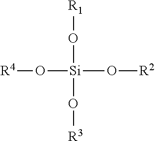
where R1 to R4 are the same or different and may comprise H or substituted or unsubstituted alkyl chains, e.g. C1 to C5 alkyl chains. Preferably, R1 to R4 comprise methyl or ethyl groups. The silica precursor may be a dimer (or accordingly an oligomer) of the compound described above, e.g. where R2 comprises SiOR5OR6OR7, where R5 to R7 are the same or different and may comprise H or substituted or unsubstituted alkyl chains, e.g. C1 to C5 alkyl chains.

where R1 to R4 are the same or different and may comprise H or substituted or unsubstituted alkyl chains, e.g. C1 to C5 alkyl chains;
or dimers or oligomers of compound X;
water;
an alcohol;
the mixture having a silica solids content of less than 40% by weight.
| TABLE 1 |
| Erosion test results of mats of Examples |
| 1 and Comparative Examples 1 to 3 |
| Example | Erosion Test | Eroded Volume/ |
| 1 | 1 | 0 |
| 1 | 2 | 0 |
| |
1 | 28 |
| |
2 | 50 |
| |
2 | >100 |
| TABLE 2 |
| Erosion test results of mats of Examples 2 to 8 |
| % Silica Solids | ||
| Example | in Solution | Eroded Volume/ |
| 2 | 4.4 | 0 |
| 3 | 3.2 | 0 |
| 4 | 2.1 | 0 |
| 5 | 1.1 | 0.4 |
| 6 | 0.5 | 0.5 |
| 7 | 0.2 | 0.7 |
| 8 | 0.1 | 16.8 |
| TABLE 3 |
| |
| % Silica Solids | Minimum wrapping | |
| Example | in Solution | diameter/mm |
| 9 | 20 | 98 |
| 10 | 15 | 94 |
| 11 | 10 | 86 |
| 12 | 5 | 82 |
| 13 | 2 | 77 |
| |
0 | 74 |
| TABLE 4 |
| |
| % Piperidine in | |||
| Example | Solution | Gel Time/min | Eroded Volume/ |
| 14 | 1 | 10 | >50 |
| 15 | 0.5 | 15-20 | >50 |
| 16 | 0.2 | >60 | 0 |
| TABLE 5 |
| Flexibility and PP of mats of Examples 9 to 13 |
| PP (% greater than | Flexibility/ | ||
| Example | Column spacing/cm | untreated mat) | mm2N−1 |
| 17 | 2.5 | 19 | 68 |
| 18 | 2.0 | 50 | 84 |
| 19 | 1.5 | 43 | 87 |
| 20 | 1.0 | 77 | 115 |
| 21 | 0.5 | 98 | 170 |
| Untreated mat | — | 0 | 60 |
| TABLE 6 |
| PP of mats of Examples 23 to 35 |
| Example | % Silica Solids | pH/acid or base added | PP/kPa |
| 23 | 22.86 | |
145 |
| 24 | 22.86 | |
132 |
| 25 | 22.86 | |
126 |
| 26 | 22.86 | pH 8/ammonia | 127 |
| 27 | 16 | |
141 |
| 28 | 16 | |
135 |
| 29 | 16 | |
121 |
| 30 | 16 | pH 8/ammonia | 104 |
| 31 | 16 | |
133 |
| 32 | 8.4 | |
124 |
| 33 | 8.4 | |
127 |
| 34 | 8.4 | |
112 |
| 35 | 35.6 | |
137 |
| TABLE 7 |
| Drying time of mats of Examples 36 to 39 |
| Example | Drying Time | Drying Temp/° C. | PP/kPa | ||
| 36 | 1 Day | 25 | 141 | ||
| 37 | 3 |
60 | 135 | ||
| 38 | 1 |
60 | 128 | ||
| 39 | 2 hr | Ambient | 134 | ||
| TABLE 8 |
| Results of Friction Tests for Examples 40 to 41. |
| Untreated | Treated | |||
| friction | friction | Friction | ||
| Example | FGBD | measurement | measurement | Boost/% |
| 40 | 0.3 | 0.413 | 0.499 | 17 |
| 41 | 0.4 | 0.278 | 0.313 | 11 |
| 42 | 0.5 | 0.209 | 0.216 | 4 |
| TABLE 9 |
| Results of PP Test for Examples 46 and 47 |
| w/w % Silica solids in | ||
| Example | treatment solution | PP/kPa |
| 46 | 0.5 | 110 |
| 47 | 1 | 136 |
| Untreated Mat | — | 85 |
Claims (17)

Applications Claiming Priority (3)
| Application Number | Priority Date | Filing Date | Title |
|---|---|---|---|
| GB0906837.0 | 2009-04-21 | ||
| GBGB0906837.0A GB0906837D0 (en) | 2009-04-21 | 2009-04-21 | Mats |
| PCT/GB2010/050649 WO2010122337A1 (en) | 2009-04-21 | 2010-04-21 | Mats |
Publications (2)
| Publication Number | Publication Date |
|---|---|
| US20120100046A1 US20120100046A1 (en) | 2012-04-26 |
| US9631529B2 true US9631529B2 (en) | 2017-04-25 |
Family
ID=40774724
Family Applications (1)
| Application Number | Title | Priority Date | Filing Date |
|---|---|---|---|
| US13/265,714 Expired - Fee Related US9631529B2 (en) | 2009-04-21 | 2010-04-21 | Erosion resistant mounting mats |
Country Status (5)
| Country | Link |
|---|---|
| US (1) | US9631529B2 (en) |
| EP (1) | EP2422057B1 (en) |
| JP (2) | JP6033680B2 (en) |
| GB (1) | GB0906837D0 (en) |
| WO (1) | WO2010122337A1 (en) |
Families Citing this family (17)
| Publication number | Priority date | Publication date | Assignee | Title |
|---|---|---|---|---|
| GB0405477D0 (en) | 2004-03-11 | 2004-04-21 | Glaxo Group Ltd | A fluid dispensing device |
| GB0507224D0 (en) | 2005-04-09 | 2005-05-18 | Glaxo Group Ltd | A fluid dispensing device |
| BRPI0917717A2 (en) * | 2008-08-29 | 2016-02-16 | Unifrax I Llc | Mounting mat with flexible edge guard and exhaust gas treatment device built into the mounting mat. |
| EP2513442B1 (en) | 2009-12-17 | 2017-11-29 | Unifrax I LLC | An exhaust gas treatment device |
| EP2513443B1 (en) | 2009-12-17 | 2016-08-10 | Unifrax I LLC | Mounting mat for exhaust gas treatment device |
| KR20140130206A (en) * | 2009-12-17 | 2014-11-07 | 유니프랙스 아이 엘엘씨 | Multilayer mounting mat for pollution control devices |
| WO2012021817A2 (en) | 2010-08-12 | 2012-02-16 | Unifrax I Llc | Exhaust gas treatment device |
| EP2638261A4 (en) | 2010-11-11 | 2014-08-06 | Unifrax I Llc | Mounting mat and exhaust gas treatment device |
| WO2013021800A1 (en) * | 2011-08-05 | 2013-02-14 | ニチアス株式会社 | Retainer for gas processing device, gas processing device, and manufacturing methods therefor |
| JP5926084B2 (en) * | 2012-03-27 | 2016-05-25 | イビデン株式会社 | Holding sealing material, exhaust gas purification device, and manufacturing method of holding sealing material |
| US9353580B2 (en) * | 2012-05-15 | 2016-05-31 | Katch Kan Holdings Ltd. | Pipe mat and method for using same for collecting fluids draining from drill pipe |
| JP2014208990A (en) | 2013-03-27 | 2014-11-06 | ニチアス株式会社 | Gas treatment device holding material |
| CA2918056C (en) | 2013-07-22 | 2021-09-21 | Morgan Advanced Materials Plc. | Inorganic fibre compositions |
| EP3034825B1 (en) | 2014-12-18 | 2017-09-27 | 3M Innovative Properties Company | Mounting mat for an exhaust gas treatment device |
| US10894737B2 (en) | 2016-01-15 | 2021-01-19 | Thermal Ceramics Uk Limited | Apparatus and method for forming melt-formed inorganic fibres |
| GB201616662D0 (en) | 2016-09-30 | 2016-11-16 | Morgan Advanced Materials Plc | Inorganic Fibre compositions |
| GB2591039B (en) | 2020-10-23 | 2021-11-24 | Thermal Ceramics Uk Ltd | Thermal insulation |
Citations (167)
| Publication number | Priority date | Publication date | Assignee | Title |
|---|---|---|---|---|
| US3012923A (en) | 1957-09-30 | 1961-12-12 | Owens Corning Fiberglass Corp | Fibrous products and method and apparatus for producing same |
| US3224927A (en) | 1963-10-04 | 1965-12-21 | Du Pont | Forming inorganic fiber material containing cationic starch and colloidal silica |
| US3510394A (en) | 1965-01-25 | 1970-05-05 | Conwed Corp | Production of water-laid felted mineral fiber panels including use of flocculating agent |
| US3649406A (en) | 1968-12-16 | 1972-03-14 | Thomas Gordon Mcnish | Improvements in or relating to fibrous insulating materials |
| US3674621A (en) | 1969-02-25 | 1972-07-04 | Mitsubishi Rayon Co | Process of making a sheet paper |
| US3771967A (en) | 1971-12-14 | 1973-11-13 | Tenneco Inc | Catalytic reactor with monolithic element |
| US3785838A (en) | 1971-11-04 | 1974-01-15 | Du Pont | Inorganic refractory fibrous compositions |
| FR2196008A5 (en) | 1972-08-08 | 1974-03-08 | Peugeot & Renault | |
| US3798006A (en) | 1971-12-14 | 1974-03-19 | Tenneco Inc | Catalytic converter for exhuast gases |
| US3861881A (en) | 1971-12-14 | 1975-01-21 | Tenneco Inc | Catalyst converter with monolithic element |
| US3957573A (en) | 1971-11-09 | 1976-05-18 | Dainichi-Nippon Cables, Ltd. | Process for producing insulating paper where the paper is frictionally calendered |
| GB1438762A (en) | 1972-06-28 | 1976-06-09 | Ici Ltd | Fluid treatment vessel |
| US3996145A (en) | 1972-11-29 | 1976-12-07 | Imperial Chemical Industries Limited | Fibrous materials |
| US4011651A (en) | 1973-03-01 | 1977-03-15 | Imperial Chemical Industries Limited | Fibre masses |
| US4093423A (en) | 1972-10-03 | 1978-06-06 | Volkswagenwerk Aktiengesellschaft | Catalytic device for the catalytic purification of exhaust gases |
| US4101280A (en) | 1975-12-24 | 1978-07-18 | Paul Gillet Gmbh | Apparatus for purification of waste from combustion engines |
| US4142864A (en) | 1977-05-31 | 1979-03-06 | Engelhard Minerals & Chemicals Corporation | Catalytic apparatus |
| EP0009940A1 (en) | 1978-10-03 | 1980-04-16 | Isolite Babcock Refractories Company Limited | Method of making refractory fibrous material |
| US4204907A (en) | 1978-03-29 | 1980-05-27 | The Carborundum Company | Conditioned colloidal silica post impregnant to prevent binder migration |
| US4269887A (en) | 1978-11-24 | 1981-05-26 | Isolite Babcock Refractories Co., Ltd. | Ceramic fiber felt |
| US4271228A (en) | 1980-02-04 | 1981-06-02 | Hollingsworth & Vose Company | Sheet material containing exfoliated vermiculite |
| US4279864A (en) | 1978-12-04 | 1981-07-21 | Nippon Soken, Inc. | Monolithic catalyst converter |
| US4328187A (en) | 1972-07-10 | 1982-05-04 | Kali-Chemie Ag | Elastic suspension for a monolithic catalyzer body in an exhaust gas cleaning device |
| US4332852A (en) | 1978-03-29 | 1982-06-01 | Kennecott Corporation | Conditioned colloidal silica post impregnant to prevent binder migration in the production of insulation articles comprising randomly oriented refractory fibers |
| US4335077A (en) | 1972-03-21 | 1982-06-15 | Zeuna-Staerker Kg | Catalyzer for detoxifying exhaust gases from internal combustion engines |
| US4353872A (en) | 1980-03-07 | 1982-10-12 | Nissan Motor Co., Ltd. | Catalytic converter |
| US4385135A (en) | 1982-05-26 | 1983-05-24 | Minnesota Mining And Manufacturing Company | Intumescent sheet material containing low density fillers |
| GB2116476A (en) | 1982-03-03 | 1983-09-28 | George William Tomkinson | Polyolefin/polyester laminates |
| GB2125458A (en) | 1982-06-29 | 1984-03-07 | Chisso Corp | Non-woven fabrics |
| US4447345A (en) | 1981-03-09 | 1984-05-08 | Grunzweig & Hartmann Und Glasfaser Ag | Thermal insulating flexible ceramic containing flame hydrolysis produced microporous oxide aerogel |
| JPS6187614A (en) | 1984-10-08 | 1986-05-06 | Daiichi Seimo Kk | Cosmetic |
| US4617176A (en) | 1984-09-13 | 1986-10-14 | Minnesota Mining And Manufacturing Company | Catalytic converter for automotive exhaust system |
| EP0205704A2 (en) | 1985-06-18 | 1986-12-30 | Isolite Babcock Refractories Company Limited | Method of treating a blanket of ceramic fibres |
| US4693338A (en) | 1985-07-16 | 1987-09-15 | Cycles Peugeot | Exhaust muffler for a motor vehicle or the like |
| US4735757A (en) | 1981-09-30 | 1988-04-05 | Isolite Babcock Refractories Co., Ltd. | Process for producing improved ceramic fiber moldings |
| US4752515A (en) | 1985-06-17 | 1988-06-21 | Mitsubishi Chemical Industries | Alumina fiber structure |
| GB2200129A (en) | 1987-01-09 | 1988-07-27 | Lydall Inc | Compressible non-asbestos sheet material for gaskets |
| EP0279511A2 (en) | 1987-01-17 | 1988-08-24 | Mitsubishi Petrochemical Co., Ltd. | Thermally bonded nonwoven fabric |
| US4823845A (en) | 1987-09-04 | 1989-04-25 | Manville Corporation | Pipe insulation |
| EP0319299A2 (en) | 1987-12-04 | 1989-06-07 | Minnesota Mining And Manufacturing Company | Catalytic converter, particulate filter for exhaust systems |
| US4849382A (en) | 1987-02-18 | 1989-07-18 | Nichias Corporation | Lightweight refractory and process for producing the same |
| US4863700A (en) | 1985-04-16 | 1989-09-05 | Stemcor | Monolithic catalytic converter mounting arrangement |
| EP0363911A2 (en) | 1988-10-11 | 1990-04-18 | Nichias Corporation | Refractories for use in firing ceramics |
| US4927608A (en) | 1987-01-02 | 1990-05-22 | J. Eberspacher | Device for catalytic cleaning of motor vehicle exhaust gases |
| US4929429A (en) | 1988-02-11 | 1990-05-29 | Minnesota Mining And Manufacturing Company | Catalytic converter |
| EP0398130A2 (en) | 1989-05-18 | 1990-11-22 | Nippon Pillar Packing Co. Ltd. | Heat-resistant expansive member |
| US4985212A (en) | 1987-09-29 | 1991-01-15 | Kabushiki Kaisha Toshiba | Support apparatus for a ceramic honeycomb element |
| US4999168A (en) | 1989-05-01 | 1991-03-12 | The Carborundum Company | Crack resistant intumescent sheet material |
| US5002836A (en) | 1985-06-21 | 1991-03-26 | Imperial Chemical Industries Plc | Fiber-reinforced metal matrix composites |
| US5032441A (en) | 1989-05-01 | 1991-07-16 | The Carborundum Company | Intumescent conforming mounting pad |
| US5073432A (en) | 1988-08-02 | 1991-12-17 | Ngk Insulators, Ltd. | Honeycomb structure and method of producing the same |
| EP0465203A1 (en) | 1990-07-02 | 1992-01-08 | Hoechst Celanese Corporation | Improved wet laid bonded fibrous web containing bicomponent fibers including LLDPE |
| US5094074A (en) | 1990-02-23 | 1992-03-10 | Nissan Motor Co., Ltd. | Catalytic converter with metallic carrier and method for producing same |
| US5139615A (en) | 1988-12-28 | 1992-08-18 | Hercules Incorporated | Composite sheet made from mechanically delaminated vermiculite |
| US5145811A (en) | 1991-07-10 | 1992-09-08 | The Carborundum Company | Inorganic ceramic papers |
| US5151253A (en) | 1991-04-18 | 1992-09-29 | Minnesota Mining And Manufacturing Company | Catalytic converter having a monolith mounting of which is comprised of partially dehydrated vermiculite flakes |
| US5250269A (en) | 1992-05-21 | 1993-10-05 | Minnesota Mining And Manufacturing Company | Catalytic converter having a metallic monolith mounted by a heat-insulating mat of refractory ceramic fibers |
| WO1993023245A1 (en) | 1992-05-12 | 1993-11-25 | Minnesota Mining And Manufacturing Company | Fire protective flexible composite, system including same method of making the composite, and method of fire-proofing |
| US5290522A (en) | 1993-01-07 | 1994-03-01 | Minnesota Mining And Manufacturing Company | Catalytic converter mounting mat |
| US5290350A (en) | 1990-11-28 | 1994-03-01 | Rhone-Poulenc Chimie | Insulating shaped articles comprising inorganic fibrous matrices and xanthan gum/cationic starch binders |
| JPH06272549A (en) | 1993-03-19 | 1994-09-27 | Asahi Glass Co Ltd | Heat resisting seal material and seal structure |
| US5380580A (en) | 1993-01-07 | 1995-01-10 | Minnesota Mining And Manufacturing Company | Flexible nonwoven mat |
| US5384188A (en) | 1992-11-17 | 1995-01-24 | The Carborundum Company | Intumescent sheet |
| US5389716A (en) | 1992-06-26 | 1995-02-14 | Georgia-Pacific Resins, Inc. | Fire resistant cured binder for fibrous mats |
| US5419975A (en) | 1993-11-22 | 1995-05-30 | The Carborundum Company | Inorganic ceramic paper, its method of manufacture and articles produced therefrom |
| US5453116A (en) | 1994-06-13 | 1995-09-26 | Minnesota Mining And Manufacturing Company | Self supporting hot gas filter assembly |
| JPH07286514A (en) | 1994-04-15 | 1995-10-31 | Mitsubishi Chem Corp | Gripping material for exhaust emission control device |
| US5488826A (en) | 1991-09-26 | 1996-02-06 | Dry Systems Technologies | Heat isolated catalytic reactor |
| DE29518939U1 (en) | 1995-03-04 | 1996-02-22 | Zeuna Staerker Kg | Emission control device |
| US5567536A (en) | 1993-11-22 | 1996-10-22 | Unifrax Corporation | Inorganic ceramic paper, its method of manufacturing and articles produced therefrom |
| US5580532A (en) | 1993-04-22 | 1996-12-03 | Unifrax Corporation | Mounting mat for fragile structures such as catalytic converters |
| EP0765993A1 (en) | 1995-04-13 | 1997-04-02 | Mitsubishi Chemical Industries Limited | Monolith holding material, method for producing the same, catalytic converter using the monolith, and method for producing the same |
| WO1997032118A1 (en) | 1996-02-27 | 1997-09-04 | Imperial Chemical Industries Plc | Composite fibre products and processes for their production |
| EP0803643A1 (en) | 1996-04-27 | 1997-10-29 | LEISTRITZ AG & CO. Abgastechnik | Exhaust gas catalyst |
| WO1998004404A1 (en) | 1996-07-26 | 1998-02-05 | Imperial Chemical Industries Plc | Composite mat |
| EP0834936A1 (en) | 1995-03-31 | 1998-04-08 | Mitsubishi Paper Mills, Ltd. | Non-woven fabric for separator of non-aqueous electrolyte cell, and non-aqueous electrolyte cell using the same |
| GB2319247A (en) | 1996-11-09 | 1998-05-20 | Ian James Mann | An insulating refractory type material |
| US5862590A (en) | 1996-05-29 | 1999-01-26 | Ibiden Co., Ltd. | Method of manufacturing catalytic converter for the purification of exhaust gas |
| US5869010A (en) | 1995-06-30 | 1999-02-09 | Minnesota Mining And Manufacturing Company | Intumescent sheet material |
| WO1999023370A1 (en) | 1997-11-03 | 1999-05-14 | Saffil Limited | Composite mat |
| WO1999046028A1 (en) | 1998-03-11 | 1999-09-16 | Unifrax Corporation | Support element for fragile structures such as catalytic converters |
| US5955177A (en) | 1996-09-03 | 1999-09-21 | 3M Innovative Properties Company | Fire barrier mat |
| US6000131A (en) | 1996-10-15 | 1999-12-14 | Corning Incorporated. | Method of making a catalytic converter for use in an internal combustion engine |
| US6051193A (en) | 1997-02-06 | 2000-04-18 | 3M Innovative Properties Company | Multilayer intumescent sheet |
| US6101714A (en) | 1997-09-08 | 2000-08-15 | Corning Incorporated | Method of making a catalytic converter for use in an internal combustion engine |
| WO2000075496A1 (en) | 1999-06-08 | 2000-12-14 | 3M Innovative Properties Company | High temperature mat for a pollution control device |
| US6162404A (en) | 1996-08-14 | 2000-12-19 | Denso Corporation | Ceramic catalytic converter |
| US6183852B1 (en) | 1992-09-15 | 2001-02-06 | The Boeing Company | Refractory fibrous ceramic insulation and process of making same |
| US6231818B1 (en) | 1998-12-08 | 2001-05-15 | Unifrax Corporation | Amorphous non-intumescent inorganic fiber mat for low temperature exhaust gas treatment devices |
| DE19957692A1 (en) | 1999-11-30 | 2001-05-31 | Zeuna Staerker Kg | Exhaust gas purification device comprises housing and exhaust gas purification body with swelling mat that has been treated with ceramic hardener containing aluminum hydroxide |
| US6251224B1 (en) | 1999-08-05 | 2001-06-26 | Owens Corning Fiberglass Technology, Inc. | Bicomponent mats of glass fibers and pulp fibers and their method of manufacture |
| US6267843B1 (en) | 1996-03-20 | 2001-07-31 | Owens Corning Fiberglas Technology, Inc. | Wet-laid nonwoven mat and a process for making same |
| WO2001065008A1 (en) | 2000-02-28 | 2001-09-07 | Saffil Limited | Method of making fibre-based products and their use |
| US20010036427A1 (en) | 2000-03-31 | 2001-11-01 | Ngk Insulators, Ltd. | Cell structure mounting container and assembly thereof |
| WO2001083956A1 (en) | 2000-04-28 | 2001-11-08 | 3M Innovative Properties Company | Thermal insulating material and pollution control device |
| US6317976B1 (en) | 1998-12-28 | 2001-11-20 | Corning Incorporated | Method of making a catalytic converter for use in an internal combustion engine |
| US20020025904A1 (en) | 2000-08-25 | 2002-02-28 | Yoshihiko Goto | Catalyst carrier holding member, method of making the same and catalyst converter |
| US20020025750A1 (en) | 1996-07-26 | 2002-02-28 | Imperial Chemical Industries Plc. | Composite mat |
| WO2002033233A1 (en) | 2000-10-17 | 2002-04-25 | Ibiden Co., Ltd. | Holding seal material for catalytic converter and method of manufacturing the holding seal material |
| WO2002053511A1 (en) | 2000-12-28 | 2002-07-11 | 3M Innovative Properties Company | Thermal insulating material and pollution control device using the same |
| US20020127154A1 (en) | 2000-03-03 | 2002-09-12 | Foster Michael R. | Exhaust control device and method for manufacture thereof |
| JP2002276350A (en) | 2001-01-11 | 2002-09-25 | Ibiden Co Ltd | Holding seal material for catalyst converter and manufacturing method thereof, ceramic fiber assembly and ceramic fiber |
| US6468932B1 (en) | 1997-05-13 | 2002-10-22 | Richter Robin | Al2O3-containing, high-temperature resistant glass sliver with highly textile character, and products thereof |
| EP1267048A1 (en) | 2000-03-22 | 2002-12-18 | Ibiden Co., Ltd. | Catalyst converter and diesel particulate filter system |
| WO2003000414A1 (en) | 2001-06-22 | 2003-01-03 | 3M Innovative Properties Company | Catalyst carrier holding material and catalytic converter |
| US20030056861A1 (en) | 2001-09-24 | 2003-03-27 | Weaver Samuel C. | Metal matrix composites of aluminum, magnesium and titanium using calcium hexaboride |
| WO2003031368A2 (en) | 2001-10-09 | 2003-04-17 | 3M Innovative Properties Company | Compositions containing biosoluble inorganic fibers and micaceous binders |
| US6589488B1 (en) | 1998-11-19 | 2003-07-08 | Wacker-Chemie Gmbh | Molding for supporting a monolith in a catalytic converter |
| US20030185724A1 (en) | 2002-03-28 | 2003-10-02 | Toshiyuki Anji | Holding material for catalytic converter and method for producing the same |
| US6726884B1 (en) | 1996-06-18 | 2004-04-27 | 3M Innovative Properties Company | Free-standing internally insulating liner |
| US6737146B2 (en) | 2000-11-16 | 2004-05-18 | ASGLAWO GmbH Stoffe zum Dãmmen und Verstärken | Bedding mat for supporting an exhaust gas catalyst |
| US6756107B1 (en) | 1998-12-16 | 2004-06-29 | Asglawo Gmbh-Stoffe Zum Daemmen Und Verstaerken | Mounting mat for mounting an exhaust-gas catalytic converter |
| WO2004064996A2 (en) | 2003-01-22 | 2004-08-05 | 3M Innovative Properties Company | Molded three-dimensional insulator |
| EP1495807A1 (en) | 2003-06-30 | 2005-01-12 | 3M Innovative Properties Company | Mounting mat for mounting monolith in a pollution control device |
| EP1533409A1 (en) | 2002-06-28 | 2005-05-25 | Denki Kagaku Kogyo Kabushiki Kaisha | Inorganic staple fiber accumulation for holding material, process for producing the same and holding material |
| US6923942B1 (en) | 1997-05-09 | 2005-08-02 | 3M Innovative Properties Company | Compressible preform insulating liner |
| WO2005106222A1 (en) | 2004-04-14 | 2005-11-10 | 3M Innovative Properties Company | Sandwich hybrid mounting mat |
| US20050272602A1 (en) | 2004-05-18 | 2005-12-08 | Ibiden Co., Ltd. | Honeycomb structural body and exhaust gas purifying device |
| US6987076B1 (en) | 1998-09-15 | 2006-01-17 | The Morgan Crucible Company Plc | Bonded fibrous materials |
| US7033412B2 (en) | 2002-09-30 | 2006-04-25 | Unifrax Corporation | Exhaust gas treatment device and method for making the same |
| WO2006055188A1 (en) | 2004-11-18 | 2006-05-26 | 3M Innovative Properties Company | A pollution control device and inorganic fiber sheet material with a fused edge |
| WO2006065534A1 (en) | 2004-12-13 | 2006-06-22 | 3M Innovative Properties Company | Mounting mats and pollution control devices using same |
| EP1696110A1 (en) | 2005-01-25 | 2006-08-30 | Ibiden Co., Ltd. | Heat insulating member for end cone portion of exhaust gas conversion apparatus |
| US20060278323A1 (en) | 2005-06-10 | 2006-12-14 | Ibiden Co., Ltd. | Holding and sealing material and manufacturing method thereof |
| US7153796B2 (en) | 2002-01-04 | 2006-12-26 | The Morgan Crucible Company Plc | Saline soluble inorganic fibres |
| US20070065349A1 (en) | 2003-04-02 | 2007-03-22 | 3M Innovative Properties Company | Non-classified end cone insulation for catalytic converter |
| US7261864B2 (en) | 2001-06-22 | 2007-08-28 | 3M Innovative Properties Company | Catalyst carrier holding material and catalytic converter |
| EP1830043A1 (en) | 2006-03-02 | 2007-09-05 | Ibiden Co., Ltd. | Heat resistant sheet and exhaust gas cleaning apparatus |
| US20070218320A1 (en) | 2001-09-24 | 2007-09-20 | Weaver Samuel C | Metal matrix composites of aluminium, magnesium and titanium using silicon hexaboride, calcium hexaboride, silicon tetraboride, and calcium tetraboride |
| US7276280B2 (en) | 2002-12-17 | 2007-10-02 | John Dinwoodie | Fibre mats |
| WO2007143437A2 (en) | 2006-06-01 | 2007-12-13 | 3M Innovative Properties Company | Multilayer mounting mat |
| EP1905895A1 (en) | 2006-09-29 | 2008-04-02 | Ibiden Co., Ltd. | Sheet member and manufacturing method of the same, and exhaust gas processing device |
| WO2008059249A1 (en) | 2006-11-14 | 2008-05-22 | Saffil Limited | Mats |
| EP1931862A1 (en) | 2005-09-08 | 2008-06-18 | 3M Innovative Properties Company | Holding material for pollution control element and pollution control apparatus |
| EP1950035A1 (en) | 2007-01-26 | 2008-07-30 | Ibiden Co., Ltd. | Sheet member, forming method of the same, exhaust gas treatment apparatus, and muffling apparatus |
| WO2008103525A2 (en) | 2007-02-19 | 2008-08-28 | 3M Innovative Properties Company | Flexible fibrous material, pollution control device, and methods of making the same |
| US20080253939A1 (en) | 2005-10-13 | 2008-10-16 | Hornback Loyd R | Multilayer Mounting Mats and Pollution Control Devices Containing Same |
| WO2008154078A1 (en) | 2007-06-13 | 2008-12-18 | 3M Innovative Properties Company | Securable mounting material and method of making and using the same |
| WO2008156942A1 (en) | 2007-06-13 | 2008-12-24 | 3M Innovative Properties Company | Erosion resistant mounting materal and method of making and using the same |
| US20090022633A1 (en) | 2007-07-20 | 2009-01-22 | Nichias Corporation | Catalytic converter, holding material for catalytic converter and production method thereof |
| US20090060800A1 (en) | 2007-08-31 | 2009-03-05 | Unifrax I Llc | Substrate Mounting System |
| US20090060802A1 (en) | 2007-08-31 | 2009-03-05 | Unifrax I Llc | Exhaust gas treatment device |
| US20090114097A1 (en) | 2007-11-06 | 2009-05-07 | Ibiden Co., Ltd. | Mat material and exhaust gas treatment device |
| US7550118B2 (en) | 2004-04-14 | 2009-06-23 | 3M Innovative Properties Company | Multilayer mats for use in pollution control devices |
| US20090162256A1 (en) | 2004-06-29 | 2009-06-25 | Ten Eyck John D | Exhaust gas treatment device |
| US20100055004A1 (en) | 2008-08-29 | 2010-03-04 | Unifrax I Llc | Mounting mat with flexible edge protection and exhaust gas treatment device incorporating the mounting mat |
| US20100150791A1 (en) * | 2007-03-30 | 2010-06-17 | Kunze Ulrich E | Fiber mat containing an organosilicon compound and pollution control device using it |
| US20100173552A1 (en) | 2009-01-05 | 2010-07-08 | Unifrax I Llc | High strength biosoluble inorganic fiber insulation mat |
| US20100207298A1 (en) | 2007-10-09 | 2010-08-19 | Kunze Ulrich E | Method of making mounting mats for mounting a pollution control panel |
| US20100209306A1 (en) | 2007-10-09 | 2010-08-19 | Kunze Ulrich E | Mat for mounting a pollution control element for the treatment of exhaust gas |
| US20100266462A1 (en) | 2009-04-17 | 2010-10-21 | Amit Kumar | Exhaust Gas Treatment Device |
| US7820117B2 (en) | 2003-01-31 | 2010-10-26 | 3M Innovative Properties Company | System for securing the end cone or mounting mat of a pollution control device |
| US20110023430A1 (en) | 2007-08-31 | 2011-02-03 | Amit Kumar | Multiple Layer Substrate Support and Exhaust Gas Treatment Device |
| US20110033343A1 (en) | 2009-08-10 | 2011-02-10 | Fernandes Jr Sergio David | Variable basis weight mounting mat or pre-form and exhaust gas treatment device |
| US7887917B2 (en) | 2005-06-30 | 2011-02-15 | Unifrax I Llc | Inorganic fiber |
| US20110036063A1 (en) | 2009-08-14 | 2011-02-17 | Unifrax I Llc | Mounting Mat for Exhaust Gas Treatment Device |
| US20110097246A1 (en) | 2009-09-23 | 2011-04-28 | Unifrax I Llc | Low Shear Mounting Mat for Pollution Control Devices |
| US20110094419A1 (en) | 2008-12-15 | 2011-04-28 | Fernando Joseph A | Ceramic Honeycomb Structure Skin Coating |
| US20110126499A1 (en) | 2009-09-24 | 2011-06-02 | Amit Kumar | Multiple Layer Mat and Exhaust Gas Treatment Device |
| WO2011067598A1 (en) | 2009-12-01 | 2011-06-09 | Saffil Automotive Limited | Mounting mat |
| US20110150717A1 (en) | 2009-12-17 | 2011-06-23 | Unifrax I Llc | Mounting mat for exhaust gas treatment device |
| US20110150715A1 (en) | 2009-12-17 | 2011-06-23 | Unifrax I Llc | Multilayer Mounting Mat for Pollution Control Devices |
| US20110311404A1 (en) | 2010-06-16 | 2011-12-22 | Creedon Matthew J | Thermally Stable Inorganic Fibers For Exhaust Gas Treatment Device Insulating Mat |
| US20110311403A1 (en) | 2009-12-17 | 2011-12-22 | Amit Kumar | Use of Microspheres in an Exhaust Gas Treatment Device Mounting Mat |
| US20120039756A1 (en) | 2010-08-12 | 2012-02-16 | Beauharnois Mark | Exhaust Gas Treatment Device |
| US8178052B2 (en) * | 2007-06-13 | 2012-05-15 | 3M Innovative Properties Company | Repositionable mounting material, pollution control device, and methods of making the same |
| US20120183449A1 (en) | 2010-08-13 | 2012-07-19 | Unifrax I Llc | Mounting Mat with Flexible Edge Protection and Exhaust Gas Treatment Device Incorporating the Mounting Mat |
Family Cites Families (1)
| Publication number | Priority date | Publication date | Assignee | Title |
|---|---|---|---|---|
| JPS62197717U (en) * | 1986-06-09 | 1987-12-16 |
-
2009
- 2009-04-21 GB GBGB0906837.0A patent/GB0906837D0/en not_active Ceased
-
2010
- 2010-04-21 WO PCT/GB2010/050649 patent/WO2010122337A1/en active Application Filing
- 2010-04-21 US US13/265,714 patent/US9631529B2/en not_active Expired - Fee Related
- 2010-04-21 JP JP2012506578A patent/JP6033680B2/en not_active Expired - Fee Related
- 2010-04-21 EP EP10720652.6A patent/EP2422057B1/en not_active Not-in-force
-
2015
- 2015-08-12 JP JP2015159415A patent/JP6030721B2/en not_active Expired - Fee Related
Patent Citations (188)
| Publication number | Priority date | Publication date | Assignee | Title |
|---|---|---|---|---|
| US3012923A (en) | 1957-09-30 | 1961-12-12 | Owens Corning Fiberglass Corp | Fibrous products and method and apparatus for producing same |
| US3224927A (en) | 1963-10-04 | 1965-12-21 | Du Pont | Forming inorganic fiber material containing cationic starch and colloidal silica |
| US3510394A (en) | 1965-01-25 | 1970-05-05 | Conwed Corp | Production of water-laid felted mineral fiber panels including use of flocculating agent |
| US3649406A (en) | 1968-12-16 | 1972-03-14 | Thomas Gordon Mcnish | Improvements in or relating to fibrous insulating materials |
| US3674621A (en) | 1969-02-25 | 1972-07-04 | Mitsubishi Rayon Co | Process of making a sheet paper |
| US3785838A (en) | 1971-11-04 | 1974-01-15 | Du Pont | Inorganic refractory fibrous compositions |
| US3957573A (en) | 1971-11-09 | 1976-05-18 | Dainichi-Nippon Cables, Ltd. | Process for producing insulating paper where the paper is frictionally calendered |
| US3771967A (en) | 1971-12-14 | 1973-11-13 | Tenneco Inc | Catalytic reactor with monolithic element |
| US3798006A (en) | 1971-12-14 | 1974-03-19 | Tenneco Inc | Catalytic converter for exhuast gases |
| US3861881A (en) | 1971-12-14 | 1975-01-21 | Tenneco Inc | Catalyst converter with monolithic element |
| US4335077A (en) | 1972-03-21 | 1982-06-15 | Zeuna-Staerker Kg | Catalyzer for detoxifying exhaust gases from internal combustion engines |
| GB1438762A (en) | 1972-06-28 | 1976-06-09 | Ici Ltd | Fluid treatment vessel |
| US4328187A (en) | 1972-07-10 | 1982-05-04 | Kali-Chemie Ag | Elastic suspension for a monolithic catalyzer body in an exhaust gas cleaning device |
| GB1438784A (en) | 1972-08-08 | 1976-06-09 | Renault | Methods of manufacturing catalytic supports for exhaust mufflers and supports thus obtained |
| FR2196008A5 (en) | 1972-08-08 | 1974-03-08 | Peugeot & Renault | |
| US4093423A (en) | 1972-10-03 | 1978-06-06 | Volkswagenwerk Aktiengesellschaft | Catalytic device for the catalytic purification of exhaust gases |
| US3996145A (en) | 1972-11-29 | 1976-12-07 | Imperial Chemical Industries Limited | Fibrous materials |
| US4011651A (en) | 1973-03-01 | 1977-03-15 | Imperial Chemical Industries Limited | Fibre masses |
| US4101280A (en) | 1975-12-24 | 1978-07-18 | Paul Gillet Gmbh | Apparatus for purification of waste from combustion engines |
| US4142864A (en) | 1977-05-31 | 1979-03-06 | Engelhard Minerals & Chemicals Corporation | Catalytic apparatus |
| US4204907A (en) | 1978-03-29 | 1980-05-27 | The Carborundum Company | Conditioned colloidal silica post impregnant to prevent binder migration |
| US4332852A (en) | 1978-03-29 | 1982-06-01 | Kennecott Corporation | Conditioned colloidal silica post impregnant to prevent binder migration in the production of insulation articles comprising randomly oriented refractory fibers |
| EP0009940A1 (en) | 1978-10-03 | 1980-04-16 | Isolite Babcock Refractories Company Limited | Method of making refractory fibrous material |
| US4269887A (en) | 1978-11-24 | 1981-05-26 | Isolite Babcock Refractories Co., Ltd. | Ceramic fiber felt |
| US4279864A (en) | 1978-12-04 | 1981-07-21 | Nippon Soken, Inc. | Monolithic catalyst converter |
| US4271228A (en) | 1980-02-04 | 1981-06-02 | Hollingsworth & Vose Company | Sheet material containing exfoliated vermiculite |
| US4353872A (en) | 1980-03-07 | 1982-10-12 | Nissan Motor Co., Ltd. | Catalytic converter |
| US4447345A (en) | 1981-03-09 | 1984-05-08 | Grunzweig & Hartmann Und Glasfaser Ag | Thermal insulating flexible ceramic containing flame hydrolysis produced microporous oxide aerogel |
| US4735757A (en) | 1981-09-30 | 1988-04-05 | Isolite Babcock Refractories Co., Ltd. | Process for producing improved ceramic fiber moldings |
| GB2116476A (en) | 1982-03-03 | 1983-09-28 | George William Tomkinson | Polyolefin/polyester laminates |
| US4385135A (en) | 1982-05-26 | 1983-05-24 | Minnesota Mining And Manufacturing Company | Intumescent sheet material containing low density fillers |
| GB2125458A (en) | 1982-06-29 | 1984-03-07 | Chisso Corp | Non-woven fabrics |
| US4617176A (en) | 1984-09-13 | 1986-10-14 | Minnesota Mining And Manufacturing Company | Catalytic converter for automotive exhaust system |
| JPS6187614A (en) | 1984-10-08 | 1986-05-06 | Daiichi Seimo Kk | Cosmetic |
| US4863700A (en) | 1985-04-16 | 1989-09-05 | Stemcor | Monolithic catalytic converter mounting arrangement |
| US4752515A (en) | 1985-06-17 | 1988-06-21 | Mitsubishi Chemical Industries | Alumina fiber structure |
| EP0205704A2 (en) | 1985-06-18 | 1986-12-30 | Isolite Babcock Refractories Company Limited | Method of treating a blanket of ceramic fibres |
| US5002836A (en) | 1985-06-21 | 1991-03-26 | Imperial Chemical Industries Plc | Fiber-reinforced metal matrix composites |
| US4693338A (en) | 1985-07-16 | 1987-09-15 | Cycles Peugeot | Exhaust muffler for a motor vehicle or the like |
| US4927608A (en) | 1987-01-02 | 1990-05-22 | J. Eberspacher | Device for catalytic cleaning of motor vehicle exhaust gases |
| GB2200129A (en) | 1987-01-09 | 1988-07-27 | Lydall Inc | Compressible non-asbestos sheet material for gaskets |
| EP0279511A2 (en) | 1987-01-17 | 1988-08-24 | Mitsubishi Petrochemical Co., Ltd. | Thermally bonded nonwoven fabric |
| US4849382A (en) | 1987-02-18 | 1989-07-18 | Nichias Corporation | Lightweight refractory and process for producing the same |
| US4823845A (en) | 1987-09-04 | 1989-04-25 | Manville Corporation | Pipe insulation |
| US4985212A (en) | 1987-09-29 | 1991-01-15 | Kabushiki Kaisha Toshiba | Support apparatus for a ceramic honeycomb element |
| EP0319299A2 (en) | 1987-12-04 | 1989-06-07 | Minnesota Mining And Manufacturing Company | Catalytic converter, particulate filter for exhaust systems |
| US4929429A (en) | 1988-02-11 | 1990-05-29 | Minnesota Mining And Manufacturing Company | Catalytic converter |
| US5073432A (en) | 1988-08-02 | 1991-12-17 | Ngk Insulators, Ltd. | Honeycomb structure and method of producing the same |
| EP0363911A2 (en) | 1988-10-11 | 1990-04-18 | Nichias Corporation | Refractories for use in firing ceramics |
| US5139615A (en) | 1988-12-28 | 1992-08-18 | Hercules Incorporated | Composite sheet made from mechanically delaminated vermiculite |
| US4999168A (en) | 1989-05-01 | 1991-03-12 | The Carborundum Company | Crack resistant intumescent sheet material |
| US5032441A (en) | 1989-05-01 | 1991-07-16 | The Carborundum Company | Intumescent conforming mounting pad |
| EP0398130A2 (en) | 1989-05-18 | 1990-11-22 | Nippon Pillar Packing Co. Ltd. | Heat-resistant expansive member |
| US5094074A (en) | 1990-02-23 | 1992-03-10 | Nissan Motor Co., Ltd. | Catalytic converter with metallic carrier and method for producing same |
| EP0465203A1 (en) | 1990-07-02 | 1992-01-08 | Hoechst Celanese Corporation | Improved wet laid bonded fibrous web containing bicomponent fibers including LLDPE |
| US5167765A (en) | 1990-07-02 | 1992-12-01 | Hoechst Celanese Corporation | Wet laid bonded fibrous web containing bicomponent fibers including lldpe |
| US5290350A (en) | 1990-11-28 | 1994-03-01 | Rhone-Poulenc Chimie | Insulating shaped articles comprising inorganic fibrous matrices and xanthan gum/cationic starch binders |
| US5151253A (en) | 1991-04-18 | 1992-09-29 | Minnesota Mining And Manufacturing Company | Catalytic converter having a monolith mounting of which is comprised of partially dehydrated vermiculite flakes |
| US5145811A (en) | 1991-07-10 | 1992-09-08 | The Carborundum Company | Inorganic ceramic papers |
| EP0522722A1 (en) | 1991-07-10 | 1993-01-13 | The Carborundum Company | Inorganic ceramic papers |
| US5488826A (en) | 1991-09-26 | 1996-02-06 | Dry Systems Technologies | Heat isolated catalytic reactor |
| US5502937A (en) | 1992-05-12 | 1996-04-02 | Minnesota Mining And Manufacturing Company | Fire protective flexible composite insulating system |
| WO1993023245A1 (en) | 1992-05-12 | 1993-11-25 | Minnesota Mining And Manufacturing Company | Fire protective flexible composite, system including same method of making the composite, and method of fire-proofing |
| EP0573834A1 (en) | 1992-05-21 | 1993-12-15 | Minnesota Mining And Manufacturing Company | Catalytic converter having a metallic monolith mounted by a heat-insulating mat of refractory ceramic fibers |
| US5250269A (en) | 1992-05-21 | 1993-10-05 | Minnesota Mining And Manufacturing Company | Catalytic converter having a metallic monolith mounted by a heat-insulating mat of refractory ceramic fibers |
| US5389716A (en) | 1992-06-26 | 1995-02-14 | Georgia-Pacific Resins, Inc. | Fire resistant cured binder for fibrous mats |
| US6183852B1 (en) | 1992-09-15 | 2001-02-06 | The Boeing Company | Refractory fibrous ceramic insulation and process of making same |
| US5384188A (en) | 1992-11-17 | 1995-01-24 | The Carborundum Company | Intumescent sheet |
| US5482686A (en) | 1992-11-17 | 1996-01-09 | Lebold; Alan R. | Catalytic converter |
| US5290522A (en) | 1993-01-07 | 1994-03-01 | Minnesota Mining And Manufacturing Company | Catalytic converter mounting mat |
| US5380580A (en) | 1993-01-07 | 1995-01-10 | Minnesota Mining And Manufacturing Company | Flexible nonwoven mat |
| JPH06272549A (en) | 1993-03-19 | 1994-09-27 | Asahi Glass Co Ltd | Heat resisting seal material and seal structure |
| US5666726A (en) | 1993-04-22 | 1997-09-16 | Unifrax Corporation | Method of making a mounting mat for fragile structures such as catalytic converters |
| US5580532A (en) | 1993-04-22 | 1996-12-03 | Unifrax Corporation | Mounting mat for fragile structures such as catalytic converters |
| US5811063A (en) | 1993-04-22 | 1998-09-22 | Unifrax Corporation | Mounting mat for fragile structures such as catalytic converters |
| US5419975A (en) | 1993-11-22 | 1995-05-30 | The Carborundum Company | Inorganic ceramic paper, its method of manufacture and articles produced therefrom |
| US5567536A (en) | 1993-11-22 | 1996-10-22 | Unifrax Corporation | Inorganic ceramic paper, its method of manufacturing and articles produced therefrom |
| JPH07286514A (en) | 1994-04-15 | 1995-10-31 | Mitsubishi Chem Corp | Gripping material for exhaust emission control device |
| US5453116A (en) | 1994-06-13 | 1995-09-26 | Minnesota Mining And Manufacturing Company | Self supporting hot gas filter assembly |
| DE29518939U1 (en) | 1995-03-04 | 1996-02-22 | Zeuna Staerker Kg | Emission control device |
| EP0834936A1 (en) | 1995-03-31 | 1998-04-08 | Mitsubishi Paper Mills, Ltd. | Non-woven fabric for separator of non-aqueous electrolyte cell, and non-aqueous electrolyte cell using the same |
| EP0765993A1 (en) | 1995-04-13 | 1997-04-02 | Mitsubishi Chemical Industries Limited | Monolith holding material, method for producing the same, catalytic converter using the monolith, and method for producing the same |
| US5869010A (en) | 1995-06-30 | 1999-02-09 | Minnesota Mining And Manufacturing Company | Intumescent sheet material |
| WO1997032118A1 (en) | 1996-02-27 | 1997-09-04 | Imperial Chemical Industries Plc | Composite fibre products and processes for their production |
| US6267843B1 (en) | 1996-03-20 | 2001-07-31 | Owens Corning Fiberglas Technology, Inc. | Wet-laid nonwoven mat and a process for making same |
| EP0803643A1 (en) | 1996-04-27 | 1997-10-29 | LEISTRITZ AG & CO. Abgastechnik | Exhaust gas catalyst |
| US5862590A (en) | 1996-05-29 | 1999-01-26 | Ibiden Co., Ltd. | Method of manufacturing catalytic converter for the purification of exhaust gas |
| US6726884B1 (en) | 1996-06-18 | 2004-04-27 | 3M Innovative Properties Company | Free-standing internally insulating liner |
| WO1998004404A1 (en) | 1996-07-26 | 1998-02-05 | Imperial Chemical Industries Plc | Composite mat |
| US7387822B2 (en) | 1996-07-26 | 2008-06-17 | Imperial Chemical Industries Plc | Process of making a composite mat |
| US20020025750A1 (en) | 1996-07-26 | 2002-02-28 | Imperial Chemical Industries Plc. | Composite mat |
| US6162404A (en) | 1996-08-14 | 2000-12-19 | Denso Corporation | Ceramic catalytic converter |
| US5955177A (en) | 1996-09-03 | 1999-09-21 | 3M Innovative Properties Company | Fire barrier mat |
| US6000131A (en) | 1996-10-15 | 1999-12-14 | Corning Incorporated. | Method of making a catalytic converter for use in an internal combustion engine |
| GB2319247A (en) | 1996-11-09 | 1998-05-20 | Ian James Mann | An insulating refractory type material |
| US6051193A (en) | 1997-02-06 | 2000-04-18 | 3M Innovative Properties Company | Multilayer intumescent sheet |
| US6923942B1 (en) | 1997-05-09 | 2005-08-02 | 3M Innovative Properties Company | Compressible preform insulating liner |
| US6468932B1 (en) | 1997-05-13 | 2002-10-22 | Richter Robin | Al2O3-containing, high-temperature resistant glass sliver with highly textile character, and products thereof |
| US6101714A (en) | 1997-09-08 | 2000-08-15 | Corning Incorporated | Method of making a catalytic converter for use in an internal combustion engine |
| WO1999023370A1 (en) | 1997-11-03 | 1999-05-14 | Saffil Limited | Composite mat |
| WO1999046028A1 (en) | 1998-03-11 | 1999-09-16 | Unifrax Corporation | Support element for fragile structures such as catalytic converters |
| US6987076B1 (en) | 1998-09-15 | 2006-01-17 | The Morgan Crucible Company Plc | Bonded fibrous materials |
| US6589488B1 (en) | 1998-11-19 | 2003-07-08 | Wacker-Chemie Gmbh | Molding for supporting a monolith in a catalytic converter |
| US6231818B1 (en) | 1998-12-08 | 2001-05-15 | Unifrax Corporation | Amorphous non-intumescent inorganic fiber mat for low temperature exhaust gas treatment devices |
| US6855298B2 (en) | 1998-12-08 | 2005-02-15 | Unifrax Corporation | Amorphous non-intumescent inorganic fiber mat for low temperature exhaust gas treatment device |
| US6756107B1 (en) | 1998-12-16 | 2004-06-29 | Asglawo Gmbh-Stoffe Zum Daemmen Und Verstaerken | Mounting mat for mounting an exhaust-gas catalytic converter |
| US6317976B1 (en) | 1998-12-28 | 2001-11-20 | Corning Incorporated | Method of making a catalytic converter for use in an internal combustion engine |
| WO2000075496A1 (en) | 1999-06-08 | 2000-12-14 | 3M Innovative Properties Company | High temperature mat for a pollution control device |
| US6251224B1 (en) | 1999-08-05 | 2001-06-26 | Owens Corning Fiberglass Technology, Inc. | Bicomponent mats of glass fibers and pulp fibers and their method of manufacture |
| DE19957692A1 (en) | 1999-11-30 | 2001-05-31 | Zeuna Staerker Kg | Exhaust gas purification device comprises housing and exhaust gas purification body with swelling mat that has been treated with ceramic hardener containing aluminum hydroxide |
| WO2001065008A1 (en) | 2000-02-28 | 2001-09-07 | Saffil Limited | Method of making fibre-based products and their use |
| US6733628B2 (en) | 2000-02-28 | 2004-05-11 | Saffil Limited | Method of making fibre-based products and their use |
| US20020127154A1 (en) | 2000-03-03 | 2002-09-12 | Foster Michael R. | Exhaust control device and method for manufacture thereof |
| EP1267048A1 (en) | 2000-03-22 | 2002-12-18 | Ibiden Co., Ltd. | Catalyst converter and diesel particulate filter system |
| US20030049180A1 (en) | 2000-03-22 | 2003-03-13 | Koji Fukushima | Catalyst converter and diesel, particulate filter system |
| US20010036427A1 (en) | 2000-03-31 | 2001-11-01 | Ngk Insulators, Ltd. | Cell structure mounting container and assembly thereof |
| WO2001083956A1 (en) | 2000-04-28 | 2001-11-08 | 3M Innovative Properties Company | Thermal insulating material and pollution control device |
| US20020025904A1 (en) | 2000-08-25 | 2002-02-28 | Yoshihiko Goto | Catalyst carrier holding member, method of making the same and catalyst converter |
| WO2002033233A1 (en) | 2000-10-17 | 2002-04-25 | Ibiden Co., Ltd. | Holding seal material for catalytic converter and method of manufacturing the holding seal material |
| US20040052694A1 (en) | 2000-10-17 | 2004-03-18 | Yoshio Nishikawa | Holding seal material for catalytic converter and method of manufacturing the holding and seal material |
| US6737146B2 (en) | 2000-11-16 | 2004-05-18 | ASGLAWO GmbH Stoffe zum Dãmmen und Verstärken | Bedding mat for supporting an exhaust gas catalyst |
| WO2002053511A1 (en) | 2000-12-28 | 2002-07-11 | 3M Innovative Properties Company | Thermal insulating material and pollution control device using the same |
| JP2002276350A (en) | 2001-01-11 | 2002-09-25 | Ibiden Co Ltd | Holding seal material for catalyst converter and manufacturing method thereof, ceramic fiber assembly and ceramic fiber |
| US7261864B2 (en) | 2001-06-22 | 2007-08-28 | 3M Innovative Properties Company | Catalyst carrier holding material and catalytic converter |
| WO2003000414A1 (en) | 2001-06-22 | 2003-01-03 | 3M Innovative Properties Company | Catalyst carrier holding material and catalytic converter |
| US20030056861A1 (en) | 2001-09-24 | 2003-03-27 | Weaver Samuel C. | Metal matrix composites of aluminum, magnesium and titanium using calcium hexaboride |
| US20070218320A1 (en) | 2001-09-24 | 2007-09-20 | Weaver Samuel C | Metal matrix composites of aluminium, magnesium and titanium using silicon hexaboride, calcium hexaboride, silicon tetraboride, and calcium tetraboride |
| US7160503B2 (en) | 2001-09-24 | 2007-01-09 | Saffil Limited | Metal matrix composites of aluminum, magnesium and titanium using silicon hexaboride, calcium hexaboride, silicon tetraboride, and calcium tetraboride |
| WO2003031368A2 (en) | 2001-10-09 | 2003-04-17 | 3M Innovative Properties Company | Compositions containing biosoluble inorganic fibers and micaceous binders |
| US20040234436A1 (en) | 2001-10-09 | 2004-11-25 | Howorth Gary F | Compositions containing biosoluble inorganic fibers and micaceous binders |
| US7153796B2 (en) | 2002-01-04 | 2006-12-26 | The Morgan Crucible Company Plc | Saline soluble inorganic fibres |
| US20030185724A1 (en) | 2002-03-28 | 2003-10-02 | Toshiyuki Anji | Holding material for catalytic converter and method for producing the same |
| EP1533409A1 (en) | 2002-06-28 | 2005-05-25 | Denki Kagaku Kogyo Kabushiki Kaisha | Inorganic staple fiber accumulation for holding material, process for producing the same and holding material |
| US7033412B2 (en) | 2002-09-30 | 2006-04-25 | Unifrax Corporation | Exhaust gas treatment device and method for making the same |
| US7276280B2 (en) | 2002-12-17 | 2007-10-02 | John Dinwoodie | Fibre mats |
| WO2004064996A2 (en) | 2003-01-22 | 2004-08-05 | 3M Innovative Properties Company | Molded three-dimensional insulator |
| US7820117B2 (en) | 2003-01-31 | 2010-10-26 | 3M Innovative Properties Company | System for securing the end cone or mounting mat of a pollution control device |
| US20070065349A1 (en) | 2003-04-02 | 2007-03-22 | 3M Innovative Properties Company | Non-classified end cone insulation for catalytic converter |
| EP1495807A1 (en) | 2003-06-30 | 2005-01-12 | 3M Innovative Properties Company | Mounting mat for mounting monolith in a pollution control device |
| US20060154040A1 (en) | 2003-06-30 | 2006-07-13 | Merry Richard P | Mounting mat for mounting monolith in a polution control device |
| WO2005106222A1 (en) | 2004-04-14 | 2005-11-10 | 3M Innovative Properties Company | Sandwich hybrid mounting mat |
| US7550118B2 (en) | 2004-04-14 | 2009-06-23 | 3M Innovative Properties Company | Multilayer mats for use in pollution control devices |
| US20050272602A1 (en) | 2004-05-18 | 2005-12-08 | Ibiden Co., Ltd. | Honeycomb structural body and exhaust gas purifying device |
| US20110123417A1 (en) | 2004-06-29 | 2011-05-26 | Ten Eyck John D | Exhaust gas treatment device |
| US20090162256A1 (en) | 2004-06-29 | 2009-06-25 | Ten Eyck John D | Exhaust gas treatment device |
| US7971357B2 (en) | 2004-06-29 | 2011-07-05 | Unifrax I Llc | Exhaust gas treatment device and method for making the same |
| WO2006055188A1 (en) | 2004-11-18 | 2006-05-26 | 3M Innovative Properties Company | A pollution control device and inorganic fiber sheet material with a fused edge |
| WO2006065534A1 (en) | 2004-12-13 | 2006-06-22 | 3M Innovative Properties Company | Mounting mats and pollution control devices using same |
| EP1696110A1 (en) | 2005-01-25 | 2006-08-30 | Ibiden Co., Ltd. | Heat insulating member for end cone portion of exhaust gas conversion apparatus |
| US20060278323A1 (en) | 2005-06-10 | 2006-12-14 | Ibiden Co., Ltd. | Holding and sealing material and manufacturing method thereof |
| US7887917B2 (en) | 2005-06-30 | 2011-02-15 | Unifrax I Llc | Inorganic fiber |
| EP1931862A1 (en) | 2005-09-08 | 2008-06-18 | 3M Innovative Properties Company | Holding material for pollution control element and pollution control apparatus |
| US20080253939A1 (en) | 2005-10-13 | 2008-10-16 | Hornback Loyd R | Multilayer Mounting Mats and Pollution Control Devices Containing Same |
| US20070207069A1 (en) | 2006-03-02 | 2007-09-06 | Ibiden Co., Ltd. | Heat resistant sheet and exhaust gas cleaning apparatus |
| EP1830043A1 (en) | 2006-03-02 | 2007-09-05 | Ibiden Co., Ltd. | Heat resistant sheet and exhaust gas cleaning apparatus |
| WO2007143437A2 (en) | 2006-06-01 | 2007-12-13 | 3M Innovative Properties Company | Multilayer mounting mat |
| EP1905895A1 (en) | 2006-09-29 | 2008-04-02 | Ibiden Co., Ltd. | Sheet member and manufacturing method of the same, and exhaust gas processing device |
| WO2008059249A1 (en) | 2006-11-14 | 2008-05-22 | Saffil Limited | Mats |
| EP1950035A1 (en) | 2007-01-26 | 2008-07-30 | Ibiden Co., Ltd. | Sheet member, forming method of the same, exhaust gas treatment apparatus, and muffling apparatus |
| WO2008103525A2 (en) | 2007-02-19 | 2008-08-28 | 3M Innovative Properties Company | Flexible fibrous material, pollution control device, and methods of making the same |
| US8226897B2 (en) * | 2007-03-30 | 2012-07-24 | 3M Innovative Properties Company | Fiber mat containing an organosilicon compound and pollution control device using it |
| US20100150791A1 (en) * | 2007-03-30 | 2010-06-17 | Kunze Ulrich E | Fiber mat containing an organosilicon compound and pollution control device using it |
| US8617475B2 (en) * | 2007-06-13 | 2013-12-31 | 3M Innovative Properties Company | Erosion resistant mounting material and method of making and using the same |
| WO2008156942A1 (en) | 2007-06-13 | 2008-12-24 | 3M Innovative Properties Company | Erosion resistant mounting materal and method of making and using the same |
| WO2008154078A1 (en) | 2007-06-13 | 2008-12-18 | 3M Innovative Properties Company | Securable mounting material and method of making and using the same |
| US8178052B2 (en) * | 2007-06-13 | 2012-05-15 | 3M Innovative Properties Company | Repositionable mounting material, pollution control device, and methods of making the same |
| US20090022633A1 (en) | 2007-07-20 | 2009-01-22 | Nichias Corporation | Catalytic converter, holding material for catalytic converter and production method thereof |
| US20090060800A1 (en) | 2007-08-31 | 2009-03-05 | Unifrax I Llc | Substrate Mounting System |
| US20110023430A1 (en) | 2007-08-31 | 2011-02-03 | Amit Kumar | Multiple Layer Substrate Support and Exhaust Gas Treatment Device |
| US20090060802A1 (en) | 2007-08-31 | 2009-03-05 | Unifrax I Llc | Exhaust gas treatment device |
| US20100209306A1 (en) | 2007-10-09 | 2010-08-19 | Kunze Ulrich E | Mat for mounting a pollution control element for the treatment of exhaust gas |
| US20100207298A1 (en) | 2007-10-09 | 2010-08-19 | Kunze Ulrich E | Method of making mounting mats for mounting a pollution control panel |
| US20090114097A1 (en) | 2007-11-06 | 2009-05-07 | Ibiden Co., Ltd. | Mat material and exhaust gas treatment device |
| US20100055004A1 (en) | 2008-08-29 | 2010-03-04 | Unifrax I Llc | Mounting mat with flexible edge protection and exhaust gas treatment device incorporating the mounting mat |
| US20110094419A1 (en) | 2008-12-15 | 2011-04-28 | Fernando Joseph A | Ceramic Honeycomb Structure Skin Coating |
| US20100173552A1 (en) | 2009-01-05 | 2010-07-08 | Unifrax I Llc | High strength biosoluble inorganic fiber insulation mat |
| US20100266462A1 (en) | 2009-04-17 | 2010-10-21 | Amit Kumar | Exhaust Gas Treatment Device |
| US20110033343A1 (en) | 2009-08-10 | 2011-02-10 | Fernandes Jr Sergio David | Variable basis weight mounting mat or pre-form and exhaust gas treatment device |
| US20110036063A1 (en) | 2009-08-14 | 2011-02-17 | Unifrax I Llc | Mounting Mat for Exhaust Gas Treatment Device |
| US20110097246A1 (en) | 2009-09-23 | 2011-04-28 | Unifrax I Llc | Low Shear Mounting Mat for Pollution Control Devices |
| US20110126499A1 (en) | 2009-09-24 | 2011-06-02 | Amit Kumar | Multiple Layer Mat and Exhaust Gas Treatment Device |
| WO2011067598A1 (en) | 2009-12-01 | 2011-06-09 | Saffil Automotive Limited | Mounting mat |
| US20110150717A1 (en) | 2009-12-17 | 2011-06-23 | Unifrax I Llc | Mounting mat for exhaust gas treatment device |
| US20110311403A1 (en) | 2009-12-17 | 2011-12-22 | Amit Kumar | Use of Microspheres in an Exhaust Gas Treatment Device Mounting Mat |
| US20110150715A1 (en) | 2009-12-17 | 2011-06-23 | Unifrax I Llc | Multilayer Mounting Mat for Pollution Control Devices |
| US20110311404A1 (en) | 2010-06-16 | 2011-12-22 | Creedon Matthew J | Thermally Stable Inorganic Fibers For Exhaust Gas Treatment Device Insulating Mat |
| US20120039756A1 (en) | 2010-08-12 | 2012-02-16 | Beauharnois Mark | Exhaust Gas Treatment Device |
| US20120183449A1 (en) | 2010-08-13 | 2012-07-19 | Unifrax I Llc | Mounting Mat with Flexible Edge Protection and Exhaust Gas Treatment Device Incorporating the Mounting Mat |
Non-Patent Citations (10)
| Title |
|---|
| Comparative Study of Various Preparation Methods of Colloidal Silica. Nov. 22, 2010. Hyung Mi Lim et al. * |
| Gulati, Ten Eyck & Lebold. "Durable Packaging Design for Cordierite Ceramic Catalysts for Motorcycle Application" Society of Automotive Engineers Meeting, Detroit, MI, Mar. 1, 1993. |
| International Preliminary Report on Patentability completed on Jul. 13, 2011 in PCT/GB2010/050649, corresponding to U.S. Appl. No. 13/265,714. |
| International Search Report and Written Opinion mailed Sep. 28, 2010 in PCT/GB2010/050649, corresponding to U.S. Appl. No. 13/265,714. |
| Japanes Office Action for corresponding Japanese Application No. 2012-506578, mailed May 17, 2016. |
| Maret, Gulati, Lambert & Zink, Systems Durability of a Ceramic Racetrack Converter. Internationals Fuels and Lubricants Meeting, Toronto, Canada, Oct. 7-10, 1991. |
| Product Brochure-"There's More to it Than You Think, HDK-Pyrogenic Silica", Wacker Silicones, 6173/10.05/e. |
| Product Brochure—"There's More to it Than You Think, HDK—Pyrogenic Silica", Wacker Silicones, 6173/10.05/e. |
| Technical Data Sheet-"HDK N20 Pyrogenic Silica", Wacker Silicones, Version 1.0, Jun. 12, 2008. |
| Technical Data Sheet—"HDK N20 Pyrogenic Silica", Wacker Silicones, Version 1.0, Jun. 12, 2008. |
Also Published As
| Publication number | Publication date |
|---|---|
| JP2012524866A (en) | 2012-10-18 |
| WO2010122337A1 (en) | 2010-10-28 |
| EP2422057B1 (en) | 2017-01-25 |
| JP2015212552A (en) | 2015-11-26 |
| JP6033680B2 (en) | 2016-11-30 |
| GB0906837D0 (en) | 2009-06-03 |
| JP6030721B2 (en) | 2016-11-24 |
| EP2422057A1 (en) | 2012-02-29 |
| US20120100046A1 (en) | 2012-04-26 |
Similar Documents
| Publication | Publication Date | Title |
|---|---|---|
| US9631529B2 (en) | Erosion resistant mounting mats | |
| US8211373B2 (en) | Mounting mat with flexible edge protection and exhaust gas treatment device incorporating the mounting mat | |
| US8349265B2 (en) | Mounting mat with flexible edge protection and exhaust gas treatment device incorporating the mounting mat | |
| JP5336479B2 (en) | FIXABLE MOUNT MATERIAL, ITS MANUFACTURING METHOD, AND USE METHOD | |
| JP5551588B2 (en) | Corrosion-resistant mounting material and method for producing and using the same | |
| KR101152009B1 (en) | Porous ceramic filters with catalyst coatings | |
| US8007732B2 (en) | Exhaust gas treatment device | |
| US7842117B2 (en) | Holding sealer, exhaust gas processing device and manufacturing method of the same | |
| US8226897B2 (en) | Fiber mat containing an organosilicon compound and pollution control device using it | |
| US8951323B2 (en) | Multiple layer mat and exhaust gas treatment device | |
| JP2002129455A (en) | Sealing material for supporting catalyst converter, method of producing the same and catalyst converter | |
| KR20020089402A (en) | Catalyst converter and diesel particulate filter system | |
| BRPI0608162A2 (en) | Pollution control element mounting member, and, Pollution control device | |
| CA2510286A1 (en) | Fibre mats | |
| US9924564B2 (en) | Heated mat and exhaust gas treatment device | |
| EP2740914B1 (en) | Retainer for gas processing device, gas processing device, and manufacturing methods therefor | |
| KR20070039876A (en) | Holding web for an exhaust gas processing unit, associated device, production method and exhaust line | |
| CN115680847A (en) | Mat material, method for producing the same, pollution control device, and heat insulation structure |
Legal Events
| Date | Code | Title | Description |
|---|---|---|---|
| AS | Assignment |
Owner name: SAFFIL AUTOMOTIVE LIMITED, UNITED KINGDOM Free format text: ASSIGNMENT OF ASSIGNORS INTEREST;ASSIGNORS:KELSALL, ADAM;WEEKS, KELVIN;CROSS, JONATHAN;AND OTHERS;SIGNING DATES FROM 20111103 TO 20111111;REEL/FRAME:027319/0754 |
|
| STCF | Information on status: patent grant |
Free format text: PATENTED CASE |
|
| FEPP | Fee payment procedure |
Free format text: MAINTENANCE FEE REMINDER MAILED (ORIGINAL EVENT CODE: REM.); ENTITY STATUS OF PATENT OWNER: LARGE ENTITY |
|
| LAPS | Lapse for failure to pay maintenance fees |
Free format text: PATENT EXPIRED FOR FAILURE TO PAY MAINTENANCE FEES (ORIGINAL EVENT CODE: EXP.); ENTITY STATUS OF PATENT OWNER: LARGE ENTITY |
|
| STCH | Information on status: patent discontinuation |
Free format text: PATENT EXPIRED DUE TO NONPAYMENT OF MAINTENANCE FEES UNDER 37 CFR 1.362 |
|
| FP | Lapsed due to failure to pay maintenance fee |
Effective date: 20210425 |