US9612010B1 - Enhanced torch top burner - Google Patents

Enhanced torch top burner Download PDF

Info

Publication number
US9612010B1
US9612010B1 US14/100,502 US201314100502A US9612010B1 US 9612010 B1 US9612010 B1 US 9612010B1 US 201314100502 A US201314100502 A US 201314100502A US 9612010 B1 US9612010 B1 US 9612010B1
Authority
US
United States
Prior art keywords
wick
cap
torch
indention
view
Prior art date
Legal status (The legal status is an assumption and is not a legal conclusion. Google has not performed a legal analysis and makes no representation as to the accuracy of the status listed.)
Active, expires
Application number
US14/100,502
Inventor
Adam S. Kimmel
Ron White
Richard Catalano
Current Assignee (The listed assignees may be inaccurate. Google has not performed a legal analysis and makes no representation or warranty as to the accuracy of the list.)
Lamplight Farms Inc
Original Assignee
Lamplight Farms Inc
Priority date (The priority date is an assumption and is not a legal conclusion. Google has not performed a legal analysis and makes no representation as to the accuracy of the date listed.)
Filing date
Publication date
Application filed by Lamplight Farms Inc filed Critical Lamplight Farms Inc
Priority to US14/100,502 priority Critical patent/US9612010B1/en
Assigned to LAMPLIGHT FARMS INCORPORATED reassignment LAMPLIGHT FARMS INCORPORATED ASSIGNMENT OF ASSIGNORS INTEREST (SEE DOCUMENT FOR DETAILS). Assignors: CATALANO, RICHARD, KIMMEL, ADAM S., WHITE, RON
Application granted granted Critical
Publication of US9612010B1 publication Critical patent/US9612010B1/en
Active legal-status Critical Current
Adjusted expiration legal-status Critical

Links

Images

Classifications

    • FMECHANICAL ENGINEERING; LIGHTING; HEATING; WEAPONS; BLASTING
    • F23COMBUSTION APPARATUS; COMBUSTION PROCESSES
    • F23DBURNERS
    • F23D3/00Burners using capillary action
    • F23D3/02Wick burners
    • F23D3/18Details of wick burners
    • F23D3/20Flame spreaders
    • FMECHANICAL ENGINEERING; LIGHTING; HEATING; WEAPONS; BLASTING
    • F21LIGHTING
    • F21VFUNCTIONAL FEATURES OR DETAILS OF LIGHTING DEVICES OR SYSTEMS THEREOF; STRUCTURAL COMBINATIONS OF LIGHTING DEVICES WITH OTHER ARTICLES, NOT OTHERWISE PROVIDED FOR
    • F21V37/00Details of lighting devices employing combustion as light source, not otherwise provided for
    • F21V37/0004Details of lighting devices employing combustion as light source, not otherwise provided for using liquid fuel
    • F21V37/002Wicks
    • FMECHANICAL ENGINEERING; LIGHTING; HEATING; WEAPONS; BLASTING
    • F23COMBUSTION APPARATUS; COMBUSTION PROCESSES
    • F23DBURNERS
    • F23D3/00Burners using capillary action
    • F23D3/02Wick burners
    • F23D3/18Details of wick burners
    • F23D3/24Carriers for wicks

Definitions

  • This disclosure is related to liquid fueled torches in general and, more specifically, to a liquid fueled torch with flame enhancing features.
  • Patio torches also known as lawn torches or garden torches, may be used to provide lighting or decoration. Sometimes, scented oils or insect repellant oils are burned in the patio torches for additional effect.
  • a torch may include a refillable canister that accepts liquid fuel.
  • a torch may be mounted on or otherwise integrated with a decorative pole for display purposes.
  • the actual utility of a torch in terms of light or aroma given off and the ability to repel pests, may be less than desirable.
  • the wick is often too small, relatively speaking, to provide an effective amount of combustion. Even with larger diameter wicks or wicks that are extendable to create a larger surface area, air and flame control may become problematic, resulting in a flame that may still be too small to create the desired effect.
  • the invention of the present disclosure in one aspect thereof, comprises a torch burner cap.
  • the cap includes a wick holder, an indention defined in the cap and surrounding the wick holder, and a mesh insert at least partially situated within the indention in the cap and surrounding the wick holder.
  • the mesh insert comprises a plurality of vertical barriers.
  • the vertical barriers may be intersected at right angles within the indention.
  • the mesh comprises a woven wire mesh.
  • the torch burner cap includes a neck attached to an upper perimeter of the indention, the neck having a contour shaped to fit a fuel reservoir.
  • the torch burner cap may also include a skirt attached to the neck below the indention.
  • the invention of the present disclosure in another aspect thereof, comprises a torch burner cap including a fitting that is selectively attachable and detachable with a neck of a fuel reservoir, an indention atop the fitting and defining a wick holder, and a mesh insert at least partially situated within the indention.
  • the mesh insert comprises a wire screen, or a plurality of intersected vertical barriers. At least some of the plurality of intersected vertical barriers may be intersected at right angles.
  • the fitting may be threaded for selective attachment and detachment with a fuel reservoir having a threaded neck.
  • the wick holder may provide a friction fit for a fiberglass wick and suspend the wick in the fuel reservoir.
  • the burner cap may also have a skirt surrounding the fitting and sized to cover the fuel reservoir.
  • the invention of the present disclosure in another aspect thereof, comprises a liquid fueled torch having a fuel reservoir and a burner cap selectively attachable and detachable with the fuel reservoir.
  • the burner cap includes an indention proximate a top thereof, the indention providing a wick holder near a center bottom thereof.
  • the burner cap also has a mesh insert at least partially within the indention and surrounding the wick holder.
  • the mesh insert comprises a wire mesh.
  • the mesh insert may comprise a woven material of a plurality of vertical barriers. At least some of the plurality of vertical barriers may be intersected at right angles.
  • the burner cap may also include a threaded connection with the fuel reservoir and a protective skirt covering the fuel reservoir.
  • the invention of the present disclosure in another aspect thereof, comprises a torch burner cap with a neck having a wick holder.
  • a downward facing skirt and a flame bowl affix to the neck.
  • the flame bowl has a larger diameter at an upper edge than a diameter of the neck.
  • the neck is configured to affix to a liquid fuel reservoir with the skirt surrounding a portion of the reservoir.
  • the burner cap provide a flame enhancing insert in the flame bowl.
  • the flame bowl may have a diameter at the upper edge that is at least twice the diameter of the neck.
  • FIG. 1A is a perspective view of a torch burner cap according to aspects of the present disclosure.
  • FIG. 1B is a perspective view of another torch burner cap according to aspects of the present disclosure.
  • FIG. 1C is a perspective view of another torch burner cap according to aspects of the present disclosure.
  • FIG. 1D is a perspective view of another torch burner cap according to aspects of the present disclosure.
  • FIG. 2 is a side view of a first side of a torch burner cap according to aspects of the present disclosure.
  • FIG. 3 is a side view of an opposite side of the burner of FIG. 2 .
  • FIG. 4 is a side view of the burner of FIG. 2 rotated ninety degrees to the left.
  • FIG. 5 is a side view of the burner of FIG. 2 opposite that shown in FIG. 4 .
  • FIG. 6 is a superior view of the burner of FIG. 1A .
  • FIG. 7 is an inferior view of the burner of FIG. 1A .
  • FIG. 8 is an inferior perspective view of a torch burner cap according to aspects of the present disclosure.
  • FIG. 9 is a side view of a liquid fueled torch according to aspects of the present disclosure.
  • FIG. 10 is a perspective view of another torch burner cap according to aspects of the present disclosure.
  • FIG. 11 is a side view of a first side of the torch burner cap of FIG. 10 .
  • FIG. 12 is a side view of an opposite side of the burner of FIG. 10 .
  • FIG. 13 is a side view of the burner of FIG. 10 rotated ninety degrees to the left.
  • FIG. 14 is a side view of the burner of FIG. 10 opposite that shown in FIG. 13 .
  • FIG. 15 is a superior view of the burner of FIG. 10 .
  • FIG. 16 is an inferior view of the burner of FIG. 10 .
  • FIG. 17 is an inferior perspective view of the torch burner cap of FIG. 10 .
  • FIG. 18 is a side view of a liquid fueled torch utilizing the cap of FIG. 10 according to aspects of the present disclosure.
  • FIG. 1A a perspective view of a torch burner cap 100 according to aspects of the present disclosure is shown.
  • the torch burner cap 100 as shown in FIG. 1A is attachable to a liquid fuel reservoir to form a complete liquid fueled torch, as will be explained in greater detail below.
  • the cap 100 has a skirt 102 facing downward with a lower rolled edge 104 that circumscribes a lower portion of a neck 106 .
  • the neck 106 is fitted with threads 108 or other attachment means for attaching to the fuel reservoir.
  • an upper portion of the neck 106 has a rounded edge 110 rolling into an indention 112 .
  • the indention 112 is at least partially filled by a mesh insert 114 .
  • the indention 112 also defines a wick holder that retains a wick 116 in a friction fit relationship.
  • the mesh insert 114 provides a plurality of vertical barriers that fit at least partially within the indention 112 .
  • the barriers may be affixed relative to one another at regular repeating intervals and angles.
  • the mesh insert 114 defines a network of vertical barriers that intersect at right angles and therefore form a number of square openings into the indention 112 .
  • the mesh insert 114 provides for promotion of sooting or carbon buildup around the wick 116 . This sooting or carbon buildup may also enhance fuel seepage from the wick 116 , which promotes a larger and more robust flame than would otherwise be available from the wick 116 .
  • a mesh insert may take on various additional forms and embodiments.
  • the mesh insert 114 is replaced with a mesh insert 118 .
  • the mesh insert 118 may be a two or three dimensional structure comprising a series of intersected wires.
  • the wires of the insert 118 may be woven together similar to that of a screen door. In other embodiments, the wires may simply be bonded together and will not necessarily be woven.
  • the mesh insert 118 provides for fuel seepage and/or sooting and carbon buildup to promote for a larger flame effect than would otherwise be available from the wick 116 .
  • the insert 120 is once again mesh-like in that it comprises a coarse stone, rock or other heat resistant material.
  • the insert 120 is a pumice stone or other heat resistant stone.
  • the insert 120 promotes for fuel seepage and/or carbon buildup to provide for an enhanced flame.
  • the insert 122 comprises a quantity of gravel of medium coarseness.
  • the gravel 122 will be retained by the indention 112 in order to promote fuel seepage and/or carbon buildup to enhance or enlarge the flames from the wick 116 when the wick 116 is ignited.
  • FIGS. 2 and 3 provide first and second side views of the cap 100 .
  • the skirt 102 with the lower rolled edge 104 can be seen affixed to the neck 106 .
  • the neck 106 provides threads or other attachment structures 108 and a somewhat rounded upper edge 110 .
  • the wick 116 can be seen extending partially above the rounded edge 110 and also extending below the rolled edge 104 ; and therefore being suitable for insertion into a fuel reservoir.
  • FIGS. 4 and 5 show a similar viewpoint to that of FIGS. 2 and 3 with a rotation of 90 degrees relative to FIGS. 2 and 3 respectively.
  • FIG. 6 a superior view of the cap 100 is shown.
  • the superior view of FIG. 6 corresponds to the perspective view of FIG. 1A .
  • the rolled edge 104 of the skirt 102 circumscribes the skirt 102 .
  • the skirt 102 circumscribes the neck 106 .
  • a portion of the threads 108 can be seen affixed to the neck 106 .
  • the rounded edge 110 of the neck 106 flows into the indention 112 that contains the mesh insert 114 .
  • the wick holder 118 can be seen within the indention 112 retaining the wick 116 in a friction fit.
  • FIG. 7 an inferior view of the cap 100 is shown.
  • the underside of the skirt 102 and rolled edge 104 can be seen circumscribing an inner portion of the neck 106 .
  • the threads 108 can be seen on the inner portion of the neck 106 .
  • the indention 112 can be seen circumscribing the wick holder 118 , which retains the wick 116 .
  • the wick holder 118 is defined as a hollow cylinder sized to accommodate the wick 116 but retain the same in a friction fit relationship.
  • a portion of the indention 112 can also be seen inside the neck 106 . It will be appreciated that the exact contour of the indention 112 may vary. In the present embodiment, the general shape of the indention 112 is that of a cup or semi-sphere.
  • FIG. 9 a side view of a liquid fuel torch 900 is shown.
  • FIG. 9 illustrates how the various embodiments of the cap 100 may affix to a fuel reservoir 902 that is shaped to contain a quantity of liquid torch fuel 904 .
  • the reservoir 902 affixes to the neck 106 of the cap 100 via the threads 108 .
  • the cap 100 and the reservoir may be secured together in other manners. For example, a friction fit or a snap lock relationship could also be provided between the reservoir 902 and the cap 100 .
  • the reservoir 902 may be clear or translucent to allow a user to easily determine the quantity of fuel 904 remaining in the reservoir 902 .
  • the skirt 102 and/or the edge 104 also provide a support means for limiting how far into a housing or other device (not shown) the fuel reservoir 902 would be allowed to travel.
  • the entire structure 900 may be fitted into a lawn torch holder, a table torch holder, or some other device that enhances the utility of the torch 900 .
  • the cap 100 provides for an indention surrounding the wick 116 .
  • the indention contains an insert, which may be one of the many previously described.
  • the insert promotes carbonization or sooting and fuel seepage from the wick 116 into the insert and the indention 112 .
  • This configuration promotes enhanced flame effects, such as a larger flame.
  • a typical torch flame from a regular wick configuration is shown in the outline 910 .
  • An example of an enhanced flame that results from the configuration of the present disclosure is shown by the outline 912 .
  • the components of the cap 100 may be subjected to heat emanating from the flames 910 , 912 , these may be formed from a heat resistant material such as a steel or other metal alloy. Various pressing, rolling, machining, and affixing methods may be employed as needed. Some of the components of the cap 100 may also be subject to continuous exposure to torch fuel and other chemicals. These may be made impervious, or at least resistant, to such chemicals through coatings or based on the properties of the underlying materials themselves. Weather resistance may also be considered in selecting materials and/or coatings—particularly where the cap 100 may remain outdoors for extended periods of time.
  • FIG. 10 a perspective view of another torch burner cap 1000 according to aspects of the present disclosure is shown.
  • FIG. 11 is a side view of a first side of the torch burner cap of FIG. 10 and
  • FIG. 12 is a side view of an opposite side of the burner of FIG. 10 .
  • FIG. 13 is a side view of the burner of FIG. 10 rotated ninety degrees to the left and
  • FIG. 14 is a side view of the burner of FIG. 10 opposite that shown in FIG. 13 .
  • Superior and inferior views are shown in FIGS. 15 and 16 , respectively.
  • FIG. 17 is an inferior perspective view.
  • the cap 1000 has a skirt 102 with a lower rolled edge 104 that circumscribes a lower portion of a neck 106 .
  • a structure of a flame bowl 1002 with rolled edge 1004 substantially mirrors the arrangement of the skirt 102 and lower rolled edge 104 .
  • the diameter of the flame bowl 1002 (and skirt 102 ) will substantially match the diameter of the neck 106 at the point of attachment.
  • the flame bowl 1002 will be larger in diameter that the neck further away, and may be up to 2.5 to 3 times as large in diameter at the rolled edge 1004 (the skirt 102 will have similar dimensions).
  • the flame bowl 1002 is considered a large flame bowl and is suitable for producing or containing a much larger flame 912 than would ordinarily be possible from the wick 116 .
  • the flame bowl 1002 may be empty but for the wick 116 . However, in other embodiments, all or a portion of the flame bowl 1002 (aside from the wick) may be provided with a flame enhancing insert (not shown) for further enhancing flame effects.
  • the insert may be similar to that of FIG. 1A, 1B, 1C , or 1 D. It may comprise a wire or mesh insert of any porosity size. It may, instead, comprise pumice or other stone.
  • FIG. 18 is a side view of a liquid fueled torch utilizing the cap of FIG. 10 according to aspects of the present disclosure.
  • FIG. 18 illustrates how the various embodiments of the cap 1000 may affix to the fuel reservoir 902 (as discussed above with respect to FIG. 9 ).
  • the reservoir 902 affixes to the neck 106 of the cap 1000 via the threads 108 .
  • These may also attach by other means.
  • a friction fit or a snap lock relationship could also be provided between the reservoir 902 and the cap 1000 .
  • the cap 1000 may provide an insert for enhancing flame effects in the flame bowl 1002 .
  • these may be formed from a heat resistant material such as a steel or other metal alloy.
  • a heat resistant material such as a steel or other metal alloy.
  • Various pressing, rolling, machining, and affixing methods may be employed as needed.
  • Some of the components of the cap 1000 may also be subject to continuous exposure to torch fuel and other chemicals. These may be made impervious, or at least resistant, to such chemicals through coatings or based on the properties of the underlying materials themselves. Weather resistance may also be considered in selecting materials and/or coatings—particularly where the cap 1000 may remain outdoors for extended periods of time.

Abstract

A torch burner cap includes a wick holder, an indention defined in the cap and surrounding the wick holder, and a mesh insert at least partially situated within the indention in the cap and surrounding the wick holder.

Description

FIELD OF THE INVENTION
This disclosure is related to liquid fueled torches in general and, more specifically, to a liquid fueled torch with flame enhancing features.
BACKGROUND OF THE INVENTION
Patio torches, also known as lawn torches or garden torches, may be used to provide lighting or decoration. Sometimes, scented oils or insect repellant oils are burned in the patio torches for additional effect. A torch may include a refillable canister that accepts liquid fuel. A torch may be mounted on or otherwise integrated with a decorative pole for display purposes.
The actual utility of a torch, in terms of light or aroma given off and the ability to repel pests, may be less than desirable. The wick is often too small, relatively speaking, to provide an effective amount of combustion. Even with larger diameter wicks or wicks that are extendable to create a larger surface area, air and flame control may become problematic, resulting in a flame that may still be too small to create the desired effect.
What is needed is a device for addressing the above and related problems.
SUMMARY OF THE INVENTION
The invention of the present disclosure, in one aspect thereof, comprises a torch burner cap. The cap includes a wick holder, an indention defined in the cap and surrounding the wick holder, and a mesh insert at least partially situated within the indention in the cap and surrounding the wick holder.
In some embodiments, the mesh insert comprises a plurality of vertical barriers. The vertical barriers may be intersected at right angles within the indention. In other embodiments, the mesh comprises a woven wire mesh.
In some embodiments, the torch burner cap includes a neck attached to an upper perimeter of the indention, the neck having a contour shaped to fit a fuel reservoir. The torch burner cap may also include a skirt attached to the neck below the indention.
The invention of the present disclosure, in another aspect thereof, comprises a torch burner cap including a fitting that is selectively attachable and detachable with a neck of a fuel reservoir, an indention atop the fitting and defining a wick holder, and a mesh insert at least partially situated within the indention.
In various embodiments, the mesh insert comprises a wire screen, or a plurality of intersected vertical barriers. At least some of the plurality of intersected vertical barriers may be intersected at right angles. The fitting may be threaded for selective attachment and detachment with a fuel reservoir having a threaded neck. The wick holder may provide a friction fit for a fiberglass wick and suspend the wick in the fuel reservoir. The burner cap may also have a skirt surrounding the fitting and sized to cover the fuel reservoir.
The invention of the present disclosure, in another aspect thereof, comprises a liquid fueled torch having a fuel reservoir and a burner cap selectively attachable and detachable with the fuel reservoir. The burner cap includes an indention proximate a top thereof, the indention providing a wick holder near a center bottom thereof. The burner cap also has a mesh insert at least partially within the indention and surrounding the wick holder.
In some embodiments, the mesh insert comprises a wire mesh. In other embodiments, the mesh insert may comprise a woven material of a plurality of vertical barriers. At least some of the plurality of vertical barriers may be intersected at right angles. The burner cap may also include a threaded connection with the fuel reservoir and a protective skirt covering the fuel reservoir.
The invention of the present disclosure, in another aspect thereof, comprises a torch burner cap with a neck having a wick holder. A downward facing skirt and a flame bowl affix to the neck. The flame bowl has a larger diameter at an upper edge than a diameter of the neck. The neck is configured to affix to a liquid fuel reservoir with the skirt surrounding a portion of the reservoir.
Some embodiments of the burner cap provide a flame enhancing insert in the flame bowl. The flame bowl may have a diameter at the upper edge that is at least twice the diameter of the neck.
BRIEF DESCRIPTION OF THE DRAWINGS
FIG. 1A is a perspective view of a torch burner cap according to aspects of the present disclosure.
FIG. 1B is a perspective view of another torch burner cap according to aspects of the present disclosure.
FIG. 1C is a perspective view of another torch burner cap according to aspects of the present disclosure.
FIG. 1D is a perspective view of another torch burner cap according to aspects of the present disclosure.
FIG. 2 is a side view of a first side of a torch burner cap according to aspects of the present disclosure.
FIG. 3 is a side view of an opposite side of the burner of FIG. 2.
FIG. 4 is a side view of the burner of FIG. 2 rotated ninety degrees to the left.
FIG. 5 is a side view of the burner of FIG. 2 opposite that shown in FIG. 4.
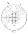
FIG. 6 is a superior view of the burner of FIG. 1A.
FIG. 7 is an inferior view of the burner of FIG. 1A.
FIG. 8 is an inferior perspective view of a torch burner cap according to aspects of the present disclosure.
FIG. 9 is a side view of a liquid fueled torch according to aspects of the present disclosure.
FIG. 10 is a perspective view of another torch burner cap according to aspects of the present disclosure.
FIG. 11 is a side view of a first side of the torch burner cap of FIG. 10.
FIG. 12 is a side view of an opposite side of the burner of FIG. 10.
FIG. 13 is a side view of the burner of FIG. 10 rotated ninety degrees to the left.
FIG. 14 is a side view of the burner of FIG. 10 opposite that shown in FIG. 13.
FIG. 15 is a superior view of the burner of FIG. 10.
FIG. 16 is an inferior view of the burner of FIG. 10.
FIG. 17 is an inferior perspective view of the torch burner cap of FIG. 10.
FIG. 18 is a side view of a liquid fueled torch utilizing the cap of FIG. 10 according to aspects of the present disclosure.
DETAILED DESCRIPTION OF THE PREFERRED EMBODIMENTS
Referring now to FIG. 1A, a perspective view of a torch burner cap 100 according to aspects of the present disclosure is shown. The torch burner cap 100 as shown in FIG. 1A is attachable to a liquid fuel reservoir to form a complete liquid fueled torch, as will be explained in greater detail below. In the present embodiment, the cap 100 has a skirt 102 facing downward with a lower rolled edge 104 that circumscribes a lower portion of a neck 106. The neck 106 is fitted with threads 108 or other attachment means for attaching to the fuel reservoir. In the present embodiment, an upper portion of the neck 106 has a rounded edge 110 rolling into an indention 112. In the present embodiment, the indention 112 is at least partially filled by a mesh insert 114. The indention 112 also defines a wick holder that retains a wick 116 in a friction fit relationship.
In the present embodiment, the mesh insert 114 provides a plurality of vertical barriers that fit at least partially within the indention 112. The barriers may be affixed relative to one another at regular repeating intervals and angles. In the present embodiment, the mesh insert 114 defines a network of vertical barriers that intersect at right angles and therefore form a number of square openings into the indention 112. In operation, the mesh insert 114 provides for promotion of sooting or carbon buildup around the wick 116. This sooting or carbon buildup may also enhance fuel seepage from the wick 116, which promotes a larger and more robust flame than would otherwise be available from the wick 116.
With reference to FIG. 1B, it can be appreciated that a mesh insert may take on various additional forms and embodiments. In FIG. 1B, the mesh insert 114 is replaced with a mesh insert 118. The mesh insert 118 may be a two or three dimensional structure comprising a series of intersected wires. In some embodiments, the wires of the insert 118 may be woven together similar to that of a screen door. In other embodiments, the wires may simply be bonded together and will not necessarily be woven. As with the embodiment of FIG. 1A, the mesh insert 118 provides for fuel seepage and/or sooting and carbon buildup to promote for a larger flame effect than would otherwise be available from the wick 116.
With reference now to FIG. 1C, yet another type of insert 120 is shown in the cap 100. The insert 120 is once again mesh-like in that it comprises a coarse stone, rock or other heat resistant material. In one embodiment, the insert 120 is a pumice stone or other heat resistant stone. As with previous embodiments, the insert 120 promotes for fuel seepage and/or carbon buildup to provide for an enhanced flame.
Referring now to FIG. 1D, a fourth type of insert 122 is shown in the indention 112 of the cap 100. In this embodiment, the insert 122 comprises a quantity of gravel of medium coarseness. The gravel 122 will be retained by the indention 112 in order to promote fuel seepage and/or carbon buildup to enhance or enlarge the flames from the wick 116 when the wick 116 is ignited.
FIGS. 2 and 3 provide first and second side views of the cap 100. Here, once again, the skirt 102 with the lower rolled edge 104 can be seen affixed to the neck 106. The neck 106 provides threads or other attachment structures 108 and a somewhat rounded upper edge 110. The wick 116 can be seen extending partially above the rounded edge 110 and also extending below the rolled edge 104; and therefore being suitable for insertion into a fuel reservoir. For completeness of illustration, FIGS. 4 and 5 show a similar viewpoint to that of FIGS. 2 and 3 with a rotation of 90 degrees relative to FIGS. 2 and 3 respectively.
Referring now to FIG. 6, a superior view of the cap 100 is shown. In the present embodiment, the superior view of FIG. 6 corresponds to the perspective view of FIG. 1A. From the superior view, it can be seen that the rolled edge 104 of the skirt 102 circumscribes the skirt 102. The skirt 102 circumscribes the neck 106. A portion of the threads 108 can be seen affixed to the neck 106. The rounded edge 110 of the neck 106 flows into the indention 112 that contains the mesh insert 114. The wick holder 118 can be seen within the indention 112 retaining the wick 116 in a friction fit.
Referring now to FIG. 7, an inferior view of the cap 100 is shown. The underside of the skirt 102 and rolled edge 104 can be seen circumscribing an inner portion of the neck 106. The threads 108 can be seen on the inner portion of the neck 106. The indention 112 can be seen circumscribing the wick holder 118, which retains the wick 116.
Referring now to FIG. 8, an inferior perspective view of the cap 100 is shown. From this viewpoint, it can be seen that, in the present embodiment, the wick holder 118 is defined as a hollow cylinder sized to accommodate the wick 116 but retain the same in a friction fit relationship. A portion of the indention 112 can also be seen inside the neck 106. It will be appreciated that the exact contour of the indention 112 may vary. In the present embodiment, the general shape of the indention 112 is that of a cup or semi-sphere.
Referring now to FIG. 9, a side view of a liquid fuel torch 900 is shown. FIG. 9 illustrates how the various embodiments of the cap 100 may affix to a fuel reservoir 902 that is shaped to contain a quantity of liquid torch fuel 904. The reservoir 902 affixes to the neck 106 of the cap 100 via the threads 108. It will be appreciated that the cap 100 and the reservoir may be secured together in other manners. For example, a friction fit or a snap lock relationship could also be provided between the reservoir 902 and the cap 100.
In some embodiments, the reservoir 902 may be clear or translucent to allow a user to easily determine the quantity of fuel 904 remaining in the reservoir 902. With the reservoir 902 securely affixed to the cap 100, the skirt 102 and/or the edge 104 also provide a support means for limiting how far into a housing or other device (not shown) the fuel reservoir 902 would be allowed to travel. For example, the entire structure 900 may be fitted into a lawn torch holder, a table torch holder, or some other device that enhances the utility of the torch 900.
As described previously, the cap 100 provides for an indention surrounding the wick 116. The indention contains an insert, which may be one of the many previously described. The insert promotes carbonization or sooting and fuel seepage from the wick 116 into the insert and the indention 112. This configuration promotes enhanced flame effects, such as a larger flame. A typical torch flame from a regular wick configuration is shown in the outline 910. An example of an enhanced flame that results from the configuration of the present disclosure is shown by the outline 912.
It will be appreciated that, as some of the components of the cap 100 may be subjected to heat emanating from the flames 910, 912, these may be formed from a heat resistant material such as a steel or other metal alloy. Various pressing, rolling, machining, and affixing methods may be employed as needed. Some of the components of the cap 100 may also be subject to continuous exposure to torch fuel and other chemicals. These may be made impervious, or at least resistant, to such chemicals through coatings or based on the properties of the underlying materials themselves. Weather resistance may also be considered in selecting materials and/or coatings—particularly where the cap 100 may remain outdoors for extended periods of time.
Referring now to FIG. 10, a perspective view of another torch burner cap 1000 according to aspects of the present disclosure is shown. FIG. 11 is a side view of a first side of the torch burner cap of FIG. 10 and FIG. 12 is a side view of an opposite side of the burner of FIG. 10. FIG. 13 is a side view of the burner of FIG. 10 rotated ninety degrees to the left and FIG. 14 is a side view of the burner of FIG. 10 opposite that shown in FIG. 13. Superior and inferior views are shown in FIGS. 15 and 16, respectively. FIG. 17 is an inferior perspective view.
From the various drawings of the torch burner cap 1000, it can be seen that there are some similarities to the cap 100 of FIGS. 1-9. In the present embodiment, the cap 1000 has a skirt 102 with a lower rolled edge 104 that circumscribes a lower portion of a neck 106. In the present embodiment, a structure of a flame bowl 1002 with rolled edge 1004 substantially mirrors the arrangement of the skirt 102 and lower rolled edge 104. The diameter of the flame bowl 1002 (and skirt 102) will substantially match the diameter of the neck 106 at the point of attachment. The flame bowl 1002 will be larger in diameter that the neck further away, and may be up to 2.5 to 3 times as large in diameter at the rolled edge 1004 (the skirt 102 will have similar dimensions). Thus the flame bowl 1002 is considered a large flame bowl and is suitable for producing or containing a much larger flame 912 than would ordinarily be possible from the wick 116.
From FIGS. 10 and 15 is can be seen that the flame bowl 1002 may be empty but for the wick 116. However, in other embodiments, all or a portion of the flame bowl 1002 (aside from the wick) may be provided with a flame enhancing insert (not shown) for further enhancing flame effects. The insert may be similar to that of FIG. 1A, 1B, 1C, or 1D. It may comprise a wire or mesh insert of any porosity size. It may, instead, comprise pumice or other stone.
FIG. 18 is a side view of a liquid fueled torch utilizing the cap of FIG. 10 according to aspects of the present disclosure. FIG. 18 illustrates how the various embodiments of the cap 1000 may affix to the fuel reservoir 902 (as discussed above with respect to FIG. 9). Here again, the reservoir 902 affixes to the neck 106 of the cap 1000 via the threads 108. These may also attach by other means. For example, a friction fit or a snap lock relationship could also be provided between the reservoir 902 and the cap 1000.
As described previously, the cap 1000 may provide an insert for enhancing flame effects in the flame bowl 1002. As some of the components of the cap 1000 may be subjected to heat emanating from the flames 912, these may be formed from a heat resistant material such as a steel or other metal alloy. Various pressing, rolling, machining, and affixing methods may be employed as needed. Some of the components of the cap 1000 may also be subject to continuous exposure to torch fuel and other chemicals. These may be made impervious, or at least resistant, to such chemicals through coatings or based on the properties of the underlying materials themselves. Weather resistance may also be considered in selecting materials and/or coatings—particularly where the cap 1000 may remain outdoors for extended periods of time.
Thus, the present invention is well adapted to carry out the objectives and attain the ends and advantages mentioned above as well as those inherent therein. While presently preferred embodiments have been described for purposes of this disclosure, numerous changes and modifications will be apparent to those of ordinary skill in the art. Such changes and modifications are encompassed within the spirit of this invention as defined by the claims.

Claims (5)

What is claimed is:
1. A torch burner cap comprising:
a fitting that is selectively attachable to and detachable from a fuel reservoir;
a cupped indention atop the fitting and defining a wick holder; and
a mesh insert rising above the indention to a wick proceeding from the wick holder such that carbon and sooting of the mesh insert from the wick occurs during combustion of fuel from the wick.
2. The torch burner cap of claim 1, wherein the mesh insert comprises a wire screen.
3. The torch burner cap of claim 1, wherein the fitting is threaded for selective attachment and detachment with a fuel reservoir having a threaded neck.
4. The torch burner cap of claim 1, wherein the wick holder provides a friction fit for a fiberglass wick and suspends the wick in the fuel reservoir.
5. The torch burner cap of claim 1, further comprising a skirt surrounding the fitting and sized to cover the fuel reservoir.
US14/100,502 2013-12-09 2013-12-09 Enhanced torch top burner Active 2035-01-07 US9612010B1 (en)

Priority Applications (1)

Application Number Priority Date Filing Date Title
US14/100,502 US9612010B1 (en) 2013-12-09 2013-12-09 Enhanced torch top burner

Applications Claiming Priority (1)

Application Number Priority Date Filing Date Title
US14/100,502 US9612010B1 (en) 2013-12-09 2013-12-09 Enhanced torch top burner

Publications (1)

Publication Number Publication Date
US9612010B1 true US9612010B1 (en) 2017-04-04

Family

ID=58419129

Family Applications (1)

Application Number Title Priority Date Filing Date
US14/100,502 Active 2035-01-07 US9612010B1 (en) 2013-12-09 2013-12-09 Enhanced torch top burner

Country Status (1)

Country Link
US (1) US9612010B1 (en)

Cited By (2)

* Cited by examiner, † Cited by third party
Publication number Priority date Publication date Assignee Title
US20220170629A1 (en) * 2020-12-02 2022-06-02 Lamplight Farms Incorporated Ready to light fuel container
US20230065573A1 (en) * 2021-09-02 2023-03-02 Haier Us Appliance Solutions, Inc. Pod mounting interface for an indoor garden center

Citations (44)

* Cited by examiner, † Cited by third party
Publication number Priority date Publication date Assignee Title
US243134A (en) 1881-06-21 Eichs
US1705877A (en) 1926-10-13 1929-03-19 John J Ramsey Lantern
US2122624A (en) 1935-12-19 1938-07-05 Kilborn Sauer Company Road torch
US2313784A (en) 1939-10-05 1943-03-16 American Can Co Container
US2684182A (en) 1952-03-29 1954-07-20 Pauline H Strauss Cigarette lighter fuel filler
US2836043A (en) 1954-12-06 1958-05-27 Spethmann Otto Lighting torches
US3364704A (en) 1966-02-04 1968-01-23 Bernard J. Bernstein Automatic safety gas torch
US3727810A (en) 1970-08-05 1973-04-17 Steel Corp Can end with pivoted bonded seal slide
US4075785A (en) * 1972-10-13 1978-02-28 Candu, Inc. Method for hydroponic growing of lettuce
US4174702A (en) * 1977-10-14 1979-11-20 Rappaport Alfred A Disposable catalytic heater
USD262999S (en) 1979-04-20 1982-02-09 Joseph Spencer Candle lamp
US4477247A (en) 1982-06-16 1984-10-16 Beck-Noma Illinois Inc. Liquid fuel burning torch
US5083916A (en) 1990-01-31 1992-01-28 Glen Co. Enterprises, Inc. Fuel combustion apparatus and method
US5405262A (en) * 1994-06-07 1995-04-11 Appel; Ron I. Adjustable burning canned heating apparatus
US5584283A (en) 1993-11-15 1996-12-17 Colgate-Palmolive Company Cooking fuel container and burner having toroidal shaped burn area and flame
USD404507S (en) 1997-06-16 1999-01-19 Newell Operating Company Torch
US6010332A (en) 1988-05-23 2000-01-04 Heat-It Manufacturing, Inc. Disposable liquid fuel burner
US6345978B1 (en) 2000-06-19 2002-02-12 International Business Corporation Torch
US6435694B1 (en) 1999-06-10 2002-08-20 Aromatic Technologies, Inc. Candle with insert
US20020164554A1 (en) * 2001-03-20 2002-11-07 Kisch Michael C. Oil burning torch
US6482365B1 (en) 2001-09-14 2002-11-19 S.C. Johnson & Son, Inc. Volatile dispenser lamp
US6579090B1 (en) * 2002-02-27 2003-06-17 Robert Taubitz Liquid fuel burner
US6663258B1 (en) 1999-02-11 2003-12-16 Hartmut Kanter Portable illumination device
US6780382B2 (en) 1999-12-21 2004-08-24 S.C. Johnson & Son, Inc. Simmer plate dispenser for volatile active materials
US6802707B2 (en) 1999-12-21 2004-10-12 S.C. Johnson & Son, Inc. Melting plate candles
US20040229180A1 (en) 1999-12-21 2004-11-18 Furner Paul E. Melting plate candles
WO2004108219A1 (en) 2003-06-06 2004-12-16 Leinemann Gmbh & Co. Kg Permanently fireproof flame guard
US6857869B1 (en) 2004-04-01 2005-02-22 Cheng-Seu Sun Refillable candle stand
US20060057530A1 (en) 2004-09-10 2006-03-16 Kubicek Chris A Fuel charge for melting plate candle assembly and method of supplying liquefied fuel to a wick
US20060199129A1 (en) 2005-03-01 2006-09-07 Foremost Groups, Inc. Decorative torch for use with pressurized fuel source
US20060251997A1 (en) 2005-05-06 2006-11-09 The Coleman Company, Inc. Gaseous fuel powered Tiki torch
US7156653B1 (en) * 2005-12-06 2007-01-02 Original Ideas, Inc Torch assembly with wick cap and funnel
US20070015097A1 (en) 2005-07-15 2007-01-18 Baker Thomas M Oil burning torch having wind protector
US7232550B1 (en) 2002-09-16 2007-06-19 Tri Tech Laboratories, Inc. Combination room freshener and oil candle and method for making the same
CN101545583A (en) 2009-04-21 2009-09-30 郑志青 Solar bamboo torch
US20090294553A1 (en) 2008-05-29 2009-12-03 Wender Wang Combination light and a device for dispensing a volatile substance
US20100112503A1 (en) * 2008-10-13 2010-05-06 Daniel Masterson Large flame torch with textured flame bowl
US20120276489A1 (en) * 2011-04-28 2012-11-01 Yihong Fang Oil lamp structure
US20130027918A1 (en) 2011-07-28 2013-01-31 Ron White Combination solar and oil torch
USD679048S1 (en) 2012-04-30 2013-03-26 Lamplight Farms, Inc. Double shrouded torch
US8435029B2 (en) 2008-02-28 2013-05-07 Lamplight Farms Incorporated Touchless fill large flame torch
US8439669B2 (en) 2009-11-13 2013-05-14 Lamplight Farms Incorporated Insect repellant torch
US8550813B2 (en) 2008-02-28 2013-10-08 Lamplight Farms Incorporated No touch pour torch top
US20130323659A1 (en) 2012-05-29 2013-12-05 Ron White Torch with twist open fire bowl

Patent Citations (46)

* Cited by examiner, † Cited by third party
Publication number Priority date Publication date Assignee Title
US243134A (en) 1881-06-21 Eichs
US1705877A (en) 1926-10-13 1929-03-19 John J Ramsey Lantern
US2122624A (en) 1935-12-19 1938-07-05 Kilborn Sauer Company Road torch
US2313784A (en) 1939-10-05 1943-03-16 American Can Co Container
US2684182A (en) 1952-03-29 1954-07-20 Pauline H Strauss Cigarette lighter fuel filler
US2836043A (en) 1954-12-06 1958-05-27 Spethmann Otto Lighting torches
US3364704A (en) 1966-02-04 1968-01-23 Bernard J. Bernstein Automatic safety gas torch
US3727810A (en) 1970-08-05 1973-04-17 Steel Corp Can end with pivoted bonded seal slide
US4075785A (en) * 1972-10-13 1978-02-28 Candu, Inc. Method for hydroponic growing of lettuce
US4174702A (en) * 1977-10-14 1979-11-20 Rappaport Alfred A Disposable catalytic heater
USD262999S (en) 1979-04-20 1982-02-09 Joseph Spencer Candle lamp
US4477247A (en) 1982-06-16 1984-10-16 Beck-Noma Illinois Inc. Liquid fuel burning torch
US6010332A (en) 1988-05-23 2000-01-04 Heat-It Manufacturing, Inc. Disposable liquid fuel burner
US5083916A (en) 1990-01-31 1992-01-28 Glen Co. Enterprises, Inc. Fuel combustion apparatus and method
US5584283A (en) 1993-11-15 1996-12-17 Colgate-Palmolive Company Cooking fuel container and burner having toroidal shaped burn area and flame
US5405262A (en) * 1994-06-07 1995-04-11 Appel; Ron I. Adjustable burning canned heating apparatus
USD404507S (en) 1997-06-16 1999-01-19 Newell Operating Company Torch
US6663258B1 (en) 1999-02-11 2003-12-16 Hartmut Kanter Portable illumination device
US6435694B1 (en) 1999-06-10 2002-08-20 Aromatic Technologies, Inc. Candle with insert
US6780382B2 (en) 1999-12-21 2004-08-24 S.C. Johnson & Son, Inc. Simmer plate dispenser for volatile active materials
US6802707B2 (en) 1999-12-21 2004-10-12 S.C. Johnson & Son, Inc. Melting plate candles
US20040229180A1 (en) 1999-12-21 2004-11-18 Furner Paul E. Melting plate candles
US7247017B2 (en) 1999-12-21 2007-07-24 S.C. Johnson & Son, Inc. Melting plate candles
US6345978B1 (en) 2000-06-19 2002-02-12 International Business Corporation Torch
US20020164554A1 (en) * 2001-03-20 2002-11-07 Kisch Michael C. Oil burning torch
US6482365B1 (en) 2001-09-14 2002-11-19 S.C. Johnson & Son, Inc. Volatile dispenser lamp
US6579090B1 (en) * 2002-02-27 2003-06-17 Robert Taubitz Liquid fuel burner
US7232550B1 (en) 2002-09-16 2007-06-19 Tri Tech Laboratories, Inc. Combination room freshener and oil candle and method for making the same
WO2004108219A1 (en) 2003-06-06 2004-12-16 Leinemann Gmbh & Co. Kg Permanently fireproof flame guard
US20060144599A1 (en) 2003-06-06 2006-07-06 Christoph Leinemann Permanently fireproof flame guard
US6857869B1 (en) 2004-04-01 2005-02-22 Cheng-Seu Sun Refillable candle stand
US20060057530A1 (en) 2004-09-10 2006-03-16 Kubicek Chris A Fuel charge for melting plate candle assembly and method of supplying liquefied fuel to a wick
US20060199129A1 (en) 2005-03-01 2006-09-07 Foremost Groups, Inc. Decorative torch for use with pressurized fuel source
US20060251997A1 (en) 2005-05-06 2006-11-09 The Coleman Company, Inc. Gaseous fuel powered Tiki torch
US20070015097A1 (en) 2005-07-15 2007-01-18 Baker Thomas M Oil burning torch having wind protector
US7156653B1 (en) * 2005-12-06 2007-01-02 Original Ideas, Inc Torch assembly with wick cap and funnel
US8435029B2 (en) 2008-02-28 2013-05-07 Lamplight Farms Incorporated Touchless fill large flame torch
US8550813B2 (en) 2008-02-28 2013-10-08 Lamplight Farms Incorporated No touch pour torch top
US20090294553A1 (en) 2008-05-29 2009-12-03 Wender Wang Combination light and a device for dispensing a volatile substance
US20100112503A1 (en) * 2008-10-13 2010-05-06 Daniel Masterson Large flame torch with textured flame bowl
CN101545583A (en) 2009-04-21 2009-09-30 郑志青 Solar bamboo torch
US8439669B2 (en) 2009-11-13 2013-05-14 Lamplight Farms Incorporated Insect repellant torch
US20120276489A1 (en) * 2011-04-28 2012-11-01 Yihong Fang Oil lamp structure
US20130027918A1 (en) 2011-07-28 2013-01-31 Ron White Combination solar and oil torch
USD679048S1 (en) 2012-04-30 2013-03-26 Lamplight Farms, Inc. Double shrouded torch
US20130323659A1 (en) 2012-05-29 2013-12-05 Ron White Torch with twist open fire bowl

Non-Patent Citations (2)

* Cited by examiner, † Cited by third party
Title
Pipe-Line Denmark, "Elipse Advanced Burning Control".
Pipe-Line Denmark, "The Torch Master Brochure", Publisher: http://www.pipe-line.dk/pdf/English2007WEB.pdf.

Cited By (3)

* Cited by examiner, † Cited by third party
Publication number Priority date Publication date Assignee Title
US20220170629A1 (en) * 2020-12-02 2022-06-02 Lamplight Farms Incorporated Ready to light fuel container
US20230065573A1 (en) * 2021-09-02 2023-03-02 Haier Us Appliance Solutions, Inc. Pod mounting interface for an indoor garden center
US11723326B2 (en) * 2021-09-02 2023-08-15 Haier Us Appliance Solutions, Inc. Pod mounting interface for an indoor garden center

Similar Documents

Publication Publication Date Title
US7082714B1 (en) Light vase
US10316270B2 (en) Burner cup
US20110198550A1 (en) Finial with concealed torch for hollow post
US5807093A (en) Flameguard for outdoor torch
CA2980912C (en) Multifunction torch
US20170059155A1 (en) Candle lamp
US20060251997A1 (en) Gaseous fuel powered Tiki torch
US9612010B1 (en) Enhanced torch top burner
US20100112503A1 (en) Large flame torch with textured flame bowl
US20030036030A1 (en) Outdoor lamp with adjustable wick
US20160327270A1 (en) Torch with weighted safety snuffer
CN101715530A (en) Candle burning device
KR101514993B1 (en) Candle light
US20160223186A1 (en) Liquid candle system
KR100879055B1 (en) Double flowerpot for decorating
CN212057015U (en) Afforestation landscape lamp
WO2000037848A9 (en) Candle holders and followers for drip prevention, fragrance dispensing and auxiliary illumination
US20060072307A1 (en) Lantern
KR102175013B1 (en) Candle
KR200419109Y1 (en) The cup for candle-light assembly
KR20080001432U (en) A candle design cover
CN209495298U (en) A kind of candle holder of birdcage
US20230408071A1 (en) Pole mounted torch assembly
CN107543134A (en) Candle seals
CN204026617U (en) A kind of artistic candle holder

Legal Events

Date Code Title Description
AS Assignment

Owner name: LAMPLIGHT FARMS INCORPORATED, WISCONSIN

Free format text: ASSIGNMENT OF ASSIGNORS INTEREST;ASSIGNORS:KIMMEL, ADAM S.;WHITE, RON;CATALANO, RICHARD;REEL/FRAME:032063/0791

Effective date: 20140115

STCF Information on status: patent grant

Free format text: PATENTED CASE

FEPP Fee payment procedure

Free format text: SURCHARGE FOR LATE PAYMENT, LARGE ENTITY (ORIGINAL EVENT CODE: M1554); ENTITY STATUS OF PATENT OWNER: LARGE ENTITY

MAFP Maintenance fee payment

Free format text: PAYMENT OF MAINTENANCE FEE, 4TH YEAR, LARGE ENTITY (ORIGINAL EVENT CODE: M1551); ENTITY STATUS OF PATENT OWNER: LARGE ENTITY

Year of fee payment: 4