US9581135B2 - Cable-suspended wind energy generator - Google Patents

Cable-suspended wind energy generator Download PDF

Info

Publication number
US9581135B2
US9581135B2 US14/086,658 US201314086658A US9581135B2 US 9581135 B2 US9581135 B2 US 9581135B2 US 201314086658 A US201314086658 A US 201314086658A US 9581135 B2 US9581135 B2 US 9581135B2
Authority
US
United States
Prior art keywords
cables
craft
sail
generator
cable
Prior art date
Legal status (The legal status is an assumption and is not a legal conclusion. Google has not performed a legal analysis and makes no representation as to the accuracy of the status listed.)
Expired - Fee Related, expires
Application number
US14/086,658
Other versions
US20140152018A1 (en
Inventor
Richard H. Harrington
Ryan Klock
Current Assignee (The listed assignees may be inaccurate. Google has not performed a legal analysis and makes no representation or warranty as to the accuracy of the list.)
Harrington Electronics LLC
Original Assignee
Harrington Electronics LLC
Priority date (The priority date is an assumption and is not a legal conclusion. Google has not performed a legal analysis and makes no representation as to the accuracy of the date listed.)
Filing date
Publication date
Application filed by Harrington Electronics LLC filed Critical Harrington Electronics LLC
Priority to US14/086,658 priority Critical patent/US9581135B2/en
Assigned to Harrington Electronics LLC reassignment Harrington Electronics LLC ASSIGNMENT OF ASSIGNORS INTEREST (SEE DOCUMENT FOR DETAILS). Assignors: HARRINGTON, RICHARD H., KLOCK, RYAN
Publication of US20140152018A1 publication Critical patent/US20140152018A1/en
Application granted granted Critical
Publication of US9581135B2 publication Critical patent/US9581135B2/en
Expired - Fee Related legal-status Critical Current
Adjusted expiration legal-status Critical

Links

Images

Classifications

    • FMECHANICAL ENGINEERING; LIGHTING; HEATING; WEAPONS; BLASTING
    • F03MACHINES OR ENGINES FOR LIQUIDS; WIND, SPRING, OR WEIGHT MOTORS; PRODUCING MECHANICAL POWER OR A REACTIVE PROPULSIVE THRUST, NOT OTHERWISE PROVIDED FOR
    • F03DWIND MOTORS
    • F03D5/00Other wind motors
    • F03D5/02Other wind motors the wind-engaging parts being attached to endless chains or the like
    • FMECHANICAL ENGINEERING; LIGHTING; HEATING; WEAPONS; BLASTING
    • F05INDEXING SCHEMES RELATING TO ENGINES OR PUMPS IN VARIOUS SUBCLASSES OF CLASSES F01-F04
    • F05BINDEXING SCHEME RELATING TO WIND, SPRING, WEIGHT, INERTIA OR LIKE MOTORS, TO MACHINES OR ENGINES FOR LIQUIDS COVERED BY SUBCLASSES F03B, F03D AND F03G
    • F05B2240/00Components
    • F05B2240/90Mounting on supporting structures or systems
    • F05B2240/91Mounting on supporting structures or systems on a stationary structure
    • F05B2240/917Mounting on supporting structures or systems on a stationary structure attached to cables
    • YGENERAL TAGGING OF NEW TECHNOLOGICAL DEVELOPMENTS; GENERAL TAGGING OF CROSS-SECTIONAL TECHNOLOGIES SPANNING OVER SEVERAL SECTIONS OF THE IPC; TECHNICAL SUBJECTS COVERED BY FORMER USPC CROSS-REFERENCE ART COLLECTIONS [XRACs] AND DIGESTS
    • Y02TECHNOLOGIES OR APPLICATIONS FOR MITIGATION OR ADAPTATION AGAINST CLIMATE CHANGE
    • Y02BCLIMATE CHANGE MITIGATION TECHNOLOGIES RELATED TO BUILDINGS, e.g. HOUSING, HOUSE APPLIANCES OR RELATED END-USER APPLICATIONS
    • Y02B10/00Integration of renewable energy sources in buildings
    • Y02B10/30Wind power
    • YGENERAL TAGGING OF NEW TECHNOLOGICAL DEVELOPMENTS; GENERAL TAGGING OF CROSS-SECTIONAL TECHNOLOGIES SPANNING OVER SEVERAL SECTIONS OF THE IPC; TECHNICAL SUBJECTS COVERED BY FORMER USPC CROSS-REFERENCE ART COLLECTIONS [XRACs] AND DIGESTS
    • Y02TECHNOLOGIES OR APPLICATIONS FOR MITIGATION OR ADAPTATION AGAINST CLIMATE CHANGE
    • Y02EREDUCTION OF GREENHOUSE GAS [GHG] EMISSIONS, RELATED TO ENERGY GENERATION, TRANSMISSION OR DISTRIBUTION
    • Y02E10/00Energy generation through renewable energy sources
    • Y02E10/70Wind energy
    • Y02E10/72Wind turbines with rotation axis in wind direction
    • Y02E10/725
    • YGENERAL TAGGING OF NEW TECHNOLOGICAL DEVELOPMENTS; GENERAL TAGGING OF CROSS-SECTIONAL TECHNOLOGIES SPANNING OVER SEVERAL SECTIONS OF THE IPC; TECHNICAL SUBJECTS COVERED BY FORMER USPC CROSS-REFERENCE ART COLLECTIONS [XRACs] AND DIGESTS
    • Y02TECHNOLOGIES OR APPLICATIONS FOR MITIGATION OR ADAPTATION AGAINST CLIMATE CHANGE
    • Y02EREDUCTION OF GREENHOUSE GAS [GHG] EMISSIONS, RELATED TO ENERGY GENERATION, TRANSMISSION OR DISTRIBUTION
    • Y02E10/00Energy generation through renewable energy sources
    • Y02E10/70Wind energy
    • Y02E10/728Onshore wind turbines

Definitions

  • a wind energy generator constructed in accordance with the invention comprises at least two support towers extending up from the ground and upper and lower cables extending from one tower to another. At least one sail craft is coupled to the upper and lower cables such that wind moves the sail craft along the cables. Each sail craft is coupled to the upper and lower cables with respective upper and lower modules, one or both of which includes a wheel that rotates as the craft moves along the cables. The wheel is coupled to an electrical generator that that feeds one or both of the cables for further distribution through at least one of the towers.
  • a structure at each tower causes the craft to reverse its direction and travel back and forth between the towers.
  • the system includes four cables between the towers, including an upper pair of cables and a lower pair of cables.
  • the structure at the end towers causes each craft to reverse its direction is a spiral track interconnecting the upper and lower cables, causing the sail craft to travel to one tower on the upper pair of cables and travel to the other tower on the lower pair of cables. In this way, sail craft travelling in opposite directions to not block the wind to other craft.
  • Each craft further preferably includes a mast extending between the upper and lower modules, with at least one having a forward edge connected to the mast.
  • each sail is an elliptical sail, and more preferably, each craft uses upper and lower mirrored elliptical sails connected to the mast.
  • a boom may be provided which extends outwardly from the mast and terminates in a distal end, and wherein a portion of the sail is fastened to the boom.
  • upper and lower trailing modules that ride along the upper and lower cables, with a vertical cable extending between the upper and lower trailing modules.
  • a mechanism disposed at the distal end of the boom includes a pulley for engaging a portion of the vertical cable and a motor for operating the pulley to change the angle of the boom relative to the upper and lower cables.
  • the system may further include one or more sensors for determining wind direction or wind speed, and an electronic controller operative to adjust the angle of the boom as a function of wind direction or wind speed.
  • One or more sensors may be used for determining the power output of each generator, with the electronic controller being operative to adjust the speed of the sail craft or generator loading to maximize power output.
  • the generator functions as a motor/generator, with the electronic controller being operative to switch between motor and generator modes of operation, including the ability to stop the movement of a sail craft or cause a sail craft to move to a tower for maintenance.
  • FIG. 1 is a drawing of a sail craft constructed in accordance with the invention
  • FIG. 2A is a system overview from an orthographic perspective
  • FIG. 2B is a side view of the system
  • FIG. 2C is a top view of the system
  • FIG. 3A is an orthographic illustration of a motor/generator module
  • FIG. 3B is a right side view of the motor/generator module
  • FIG. 3C is a front view of the motor/generator module
  • FIG. 3D illustrates a motor/generator module with an open side
  • FIG. 5A is a frontal, detail drawing of a motor/generator assembly
  • FIG. 5B is a side detail drawing of the motor/generator assembly of FIG. 5A ;
  • FIG. 6 illustrates a boom deployment system
  • FIG. 7 is a detail drawing of a sail craft
  • FIG. 13 shows a graph comparing the cable sailor power output and the wind turbine output with the cable sailor sail area and the wind turbine swept area being equal;
  • FIG. 14 shows a service station, a tower, main tower cables and tower bases
  • FIG. 15 illustrates a turnaround tower
  • the cable sailor craft ( FIG. 1 ) is a wind energy device that travels along cables suspended above the ground by support towers.
  • a minimum of two parallel cables ( 11 ) are required to support the cable sailor craft and carry electrical power generated or received by the cable sailor craft to the power grid.
  • the two cables are attached to the cable sailor craft and separated vertically by a distance equal to the mast ( 12 ) of the cable sailor craft plus some additional distance needed for compliance to account for uneven cable sag.
  • the cable sailor system requires only two support towers ( FIG. 2 ).
  • the support towers ( 21 ) would nominally be positioned such that the cables ( 22 ) suspended between the support towers are perpendicular or at least transverse to the prevailing winds.
  • the suspended cables are attached to the support towers by a round section of steel ( 23 ) or other high-strength material that guides the cable sailor in a 180 degree turn at the end of each cable sailor system.
  • the helical turn rails ( 24 ) redirect the cable sailor craft 180 degrees and raise or lower the cable sailor craft altitude. The change in altitude is intended to prevent wind blockage by passing cable sailor craft.
  • the suspended cables will typically be a high tensile stainless steel to prevent corrosion and carry electrical power to or from the cable sailor craft.
  • the cable sailor craft generates electrical power through two or more teardrop shaped motor/generator (MG) modules ( 31 shown in FIG. 3 ).
  • the MG modules contain one or more alternating or direct current, radial or pancake electrical motor/generators ( 32 ) ( FIGS. 4 and 5 ).
  • each motor/generator is rated for between 10 and 20 horsepower, or in alternative units, 7.5 to 15.0 kW.
  • Multiple motor generators within each MG module may be used to increase the power output of an individual cable sailor craft while not compromising the tear drop shape of the MG module.
  • Each cable sailor craft will actively monitor and control the generated electrical voltage phase such that the electrical power is transferred to the upper and lower suspended cables. If the electrical voltage phase is not actively monitored, high circulating currents may flow within the suspended cables and dissipate the generated electrical power as wasted heat. This voltage monitoring and control will be carried out by a system central, or cable sailor craft embedded computer that controls power switching devices such as insulated-gate bipolar transistors.
  • the trailing MG modules contain idler pulleys ( 14 ) which ride along the suspended cables and are connected to smaller diameter cables ( 61 ) which run to the Boom Deployment (BD) system ( 15 ) ( FIG. 6 ).
  • the BD system is composed or an electrical servo motor ( 62 ) that drives a cable spindle separated into two sections ( 63 ). Each section of the cable spindle is fastened to and contains the spooled cable that runs to the upper and lower trailing MG modules.
  • the electrical servo motor is controlled by an embedded computer that accounts for various input variables such as electrical power generation output, apparent wind speed, apparent wind direction, cable sailor craft speed, and inter cable sailor craft distance.
  • the first mode will be used as the cable sailor travels between supporting towers and is generating power.
  • a vane anemometer determines the apparent wind direction and speed with respect to the moving cable sailor craft and feeds this information to the embedded controller.
  • the embedded controller will then process the apparent wind direction and speed using an algorithm tailored to the particular locale and actuate the BD system to achieve the appropriate boom angle.
  • the position of the BD system electrical servo motor, and corresponding angle of the boom will typically be detected using a commercially available optical shaft encoder or Hall Effect sensor. These particular sensors are well suited to this application due to their nearly solid-state design, aside from the bearings and shaft of the optical encoder or Hall Effect sensor.
  • the cable sailor system composed of one or more cable sailor craft, the supporting cables, and supporting towers, will be electrically interfaced with the commercial power grid through one or more electrical transformers which will boost the cable sailor generated voltage to the appropriate level.
  • the commercial power grid is typically operated at 117 volts alternating current at 60 Hertz or at 220 volts alternating current at 50 Hertz in many foreign countries.
  • industrial or residential installations may connect directly to a dedicated cable sailor system if the situation so warrants.
  • Reference 803 shows the bottom of the over/under elliptical sail. This can be made of common sail cloth, or of photo/voltaic material which can be added to the motor generator voltage to further increase the power output of the cable sailor.
  • Mast 804 may be made of an aluminum tube. If the sails are photo-voltaic, the mast is also used to carry the wire cables connecting to the photo-voltaic cells.
  • FIG. 10 The boom and its pulley assembly are shown in FIG. 10 .
  • the pulley 1001 is turned by the motor gearbox assembly 1002 to control the boom position.
  • 1003 is the boom and 1000 and 1004 are the cables that connect to the motor/generator assembly.
  • FIG. 11 shows the turn-around towers, also shown in FIG. 14 .
  • Item 1100 is a support rail for the cable sailors 1101 , 1105 to both turn 180 degrees and also change altitude to prevent wind blockage to cable sailors traversing in the opposite direction.
  • the support rail is also shown on FIG. 15 as 1503 .
  • Service cables 1102 are connected between the service station 1103 and the switch assembly 1104 and 1106 .
  • the service cables 1102 provide both mechanical support and electrical energy to the cable sailor motor/generator traversing from the Service station 1103 and the tower.
  • FIG. 12 is a graph that shows the cable sailor power output versus its speed along the tower cables. The three different curves show two different versions of the cable sailor in the University of Michigan 5 ⁇ 7 foot wind tunnel and also a Computational Fluid Dynamics (CFD) simulation.
  • FIG. 13 is a graph comparing the cable sailor Power output and the Wind Turbine output with the cable sailor sail area and the wind turbine swept area being equal. The cable sailor exhibits a factor of 2.23 advantage over the average wind turbine power output at 28 MPH wind speed.
  • FIG. 14 shows the service station 1402 , a tower 1400 , main tower cables 1401 and tower bases 1403 .
  • FIG. 15 shows a turnaround tower showing the cable sailor reversing directions as well as changing heights.

Abstract

An electrical generation system is based upon sail craft that move between towers through wind power. The system includes at least two support towers (or support structures on buildings, for example), and upper and lower cables extending from one tower to another. At least one sail craft is coupled to the upper and lower cables such that wind moves the sail craft along the cables. Each sail craft is coupled to the upper and lower cables with respective upper and lower modules, one or both of which includes a wheel that rotates as the craft moves along the cables. The wheel is coupled to an electrical generator that that feeds one or both of the cables for further distribution through at least one of the towers. A structure at each tower causes the craft to reverse its direction and travel back and forth between the towers in such a way that sail craft travelling in opposite directions to not block the wind to other craft.

Description

REFERENCE TO RELATED APPLICATION
This application claims priority from U.S. Provisional Patent Application Ser. No. 61/728,941, filed Nov. 21, 2012, the entire content of which is incorporated herein by reference.
FIELD OF THE INVENTION
This invention relates generally to wind power and, in particular, to an electrical generation system based upon sail craft that move between towers through wind power.
BACKGROUND OF THE INVENTION
The advantages of wind power are many. It is widely available and does not require flowing water or sources of fuel. Harnessing the wind dates back to the first sailboat. Wind-powered machines have ground grain and pumped water for hundreds of years. With the development of electricity, wind power found new applications in lighting buildings remote from centrally-generated power. Throughout the 20th century, small wind plants evolved for farms and residences, while larger utility-scale wind generators were connected to electricity grids for power in remote locations.
Today, wind powered generators range in size from small plants for battery charging at isolated residences, to expansive offshore wind farms that provide electricity to national electrical networks. Multi-megawatt turbine technologies in use today include advanced aerodynamic, structural, and acoustic engineering design features such as steel tube towers, variable-speed generators, composite blade materials and partial-span pitch control. In 1987, the MOD-5B was the largest single wind turbine operating in the world with a rotor diameter of nearly 100 meters and a rated power of 3.2 megawatts.
However, not all the energy of blowing wind can be harvested, since conservation of mass requires that as much mass of air exits the turbine as enters it. Betz' law gives the maximal achievable extraction of wind power by a wind turbine as 59 percent of the total kinetic energy of the air flowing through the turbine. Further inefficiencies, such as rotor blade friction and drag, gearbox losses, generator and converter losses, reduce the power delivered by a wind turbine. Commercial utility-connected turbines deliver about 75 percent of the Betz limit of power extractable from the wind, at rated operating speed.
Conventional wind turbines face a number of obstacles, including intermittency, space requirements, complaints from homeowners; as such, alternative technologies are being given more serious consideration. One alternative is the airborne generator, the basic premise of which is to tether a device to the ground and let it fly around in the strong winds like a kite, either generating power and sending it down a tether to the ground or using the tether itself to produce electricity at its base.
One example, the Ampyx's PowerPlane, is a glider that generates electricity by pulling on its tether, which is connected to a ground-mounted generator. The PowerPlane glides around between 1,000 and 2,000 feet; the next iteration of this design should generate 250 to 500 kilowatts continuously. There are also inflatable designs, as well as a soft-wing kite design from North Carolina-based Windlift that uses a 40-square-meter wing flying at a maximum altitude of 500 feet, with the controls and generator on the ground.
But scaling up airborne prototypes will not be easy without strong government support. In order to be viable, airborne devices would need to stay aloft for long periods of time with little maintenance required. Another challenge is regulation, since airborne systems are so large and consume such a large volume of airspace.
SUMMARY OF THE INVENTION
This invention resides in an electrical generation system based upon sail craft that move between towers through wind power. A wind energy generator constructed in accordance with the invention comprises at least two support towers extending up from the ground and upper and lower cables extending from one tower to another. At least one sail craft is coupled to the upper and lower cables such that wind moves the sail craft along the cables. Each sail craft is coupled to the upper and lower cables with respective upper and lower modules, one or both of which includes a wheel that rotates as the craft moves along the cables. The wheel is coupled to an electrical generator that that feeds one or both of the cables for further distribution through at least one of the towers.
A structure at each tower causes the craft to reverse its direction and travel back and forth between the towers. In the preferred embodiment, the system includes four cables between the towers, including an upper pair of cables and a lower pair of cables. The structure at the end towers causes each craft to reverse its direction is a spiral track interconnecting the upper and lower cables, causing the sail craft to travel to one tower on the upper pair of cables and travel to the other tower on the lower pair of cables. In this way, sail craft travelling in opposite directions to not block the wind to other craft. There may also be support towers like the center tower shown in FIG. 14. There may be one or more cable support towers that are placed between the end towers that do not cause the cable sailor to turn around.
Each craft further preferably includes a mast extending between the upper and lower modules, with at least one having a forward edge connected to the mast. In the preferred embodiment, each sail is an elliptical sail, and more preferably, each craft uses upper and lower mirrored elliptical sails connected to the mast. A boom may be provided which extends outwardly from the mast and terminates in a distal end, and wherein a portion of the sail is fastened to the boom. In this configuration, upper and lower trailing modules that ride along the upper and lower cables, with a vertical cable extending between the upper and lower trailing modules. A mechanism disposed at the distal end of the boom includes a pulley for engaging a portion of the vertical cable and a motor for operating the pulley to change the angle of the boom relative to the upper and lower cables.
The system may further include one or more sensors for determining wind direction or wind speed, and an electronic controller operative to adjust the angle of the boom as a function of wind direction or wind speed. One or more sensors may be used for determining the power output of each generator, with the electronic controller being operative to adjust the speed of the sail craft or generator loading to maximize power output. In preferred embodiments, the generator functions as a motor/generator, with the electronic controller being operative to switch between motor and generator modes of operation, including the ability to stop the movement of a sail craft or cause a sail craft to move to a tower for maintenance.
BRIEF DESCRIPTION OF THE DRAWINGS
FIG. 1 is a drawing of a sail craft constructed in accordance with the invention;
FIG. 2A is a system overview from an orthographic perspective;
FIG. 2B is a side view of the system;
FIG. 2C is a top view of the system
FIG. 3A is an orthographic illustration of a motor/generator module;
FIG. 3B is a right side view of the motor/generator module;
FIG. 3C is a front view of the motor/generator module;
FIG. 3D illustrates a motor/generator module with an open side;
FIG. 3E is a view of a motor/generator module seen from a different perspective;
FIG. 4 depicts a motor/generator assembly;
FIG. 5A is a frontal, detail drawing of a motor/generator assembly;
FIG. 5B is a side detail drawing of the motor/generator assembly of FIG. 5A;
FIG. 6 illustrates a boom deployment system;
FIG. 7 is a detail drawing of a sail craft;
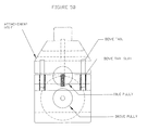
FIG. 8 is another detail drawing of a sail craft;
FIG. 9 depicts a motor/generator aero pod;
FIG. 10 shows a boom and pulley assembly;
FIG. 11 illustrates turn-around towers also shown in FIGS. 14 and 15;
FIG. 12 is a graph that shows the cable sailor power output versus its speed along the tower cables;
FIG. 13 shows a graph comparing the cable sailor power output and the wind turbine output with the cable sailor sail area and the wind turbine swept area being equal;
FIG. 14 shows a service station, a tower, main tower cables and tower bases; and
FIG. 15 illustrates a turnaround tower.
DETAILED DESCRIPTION OF THE INVENTION
This invention is directed to a wind energy system referred to herein as the “cable sailor.” The cable sailor craft (FIG. 1) is a wind energy device that travels along cables suspended above the ground by support towers. A minimum of two parallel cables (11) are required to support the cable sailor craft and carry electrical power generated or received by the cable sailor craft to the power grid. The two cables are attached to the cable sailor craft and separated vertically by a distance equal to the mast (12) of the cable sailor craft plus some additional distance needed for compliance to account for uneven cable sag.
In the simplest form, the cable sailor system requires only two support towers (FIG. 2). The support towers (21) would nominally be positioned such that the cables (22) suspended between the support towers are perpendicular or at least transverse to the prevailing winds. The suspended cables are attached to the support towers by a round section of steel (23) or other high-strength material that guides the cable sailor in a 180 degree turn at the end of each cable sailor system. The helical turn rails (24) redirect the cable sailor craft 180 degrees and raise or lower the cable sailor craft altitude. The change in altitude is intended to prevent wind blockage by passing cable sailor craft. The suspended cables will typically be a high tensile stainless steel to prevent corrosion and carry electrical power to or from the cable sailor craft.
The cable sailor craft generates electrical power through two or more teardrop shaped motor/generator (MG) modules (31 shown in FIG. 3). The MG modules contain one or more alternating or direct current, radial or pancake electrical motor/generators (32) (FIGS. 4 and 5). In one embodiment, each motor/generator is rated for between 10 and 20 horsepower, or in alternative units, 7.5 to 15.0 kW. Multiple motor generators within each MG module may be used to increase the power output of an individual cable sailor craft while not compromising the tear drop shape of the MG module.
As an example, consider a single cable sailor craft in a 30 mile per hour crosswind, with two of its MG modules each containing four motor/generators producing electrical power at a rate of 15 horse power. By simple arithmetic we see that the cable sailor craft is producing nearly 94 kilowatts of electrical power. Furthermore, by considering that multiple cable sailor craft may occupy the same suspended cable and support tower system, we see that nearly 1 mega-watt of electrical power may be produced by as few as 11 cable sailor craft.
Each cable sailor craft will actively monitor and control the generated electrical voltage phase such that the electrical power is transferred to the upper and lower suspended cables. If the electrical voltage phase is not actively monitored, high circulating currents may flow within the suspended cables and dissipate the generated electrical power as wasted heat. This voltage monitoring and control will be carried out by a system central, or cable sailor craft embedded computer that controls power switching devices such as insulated-gate bipolar transistors.
The trailing MG modules contain idler pulleys (14) which ride along the suspended cables and are connected to smaller diameter cables (61) which run to the Boom Deployment (BD) system (15) (FIG. 6). The BD system is composed or an electrical servo motor (62) that drives a cable spindle separated into two sections (63). Each section of the cable spindle is fastened to and contains the spooled cable that runs to the upper and lower trailing MG modules. The electrical servo motor is controlled by an embedded computer that accounts for various input variables such as electrical power generation output, apparent wind speed, apparent wind direction, cable sailor craft speed, and inter cable sailor craft distance.
The embedded computer calculates the appropriate boom angle and directs the electrical servo motor to let out or spool the cable accordingly. When executing a turn at the end of the cable sailor system, the BD system will act to spool the cable, bringing the boom to mid craft and preventing the boom from swinging violently from one side to another due to the change in apparent wind direction. To perform these actions, the cable sailor embedded controller will operate in two distinct modes.
The first mode will be used as the cable sailor travels between supporting towers and is generating power. During this time, a vane anemometer determines the apparent wind direction and speed with respect to the moving cable sailor craft and feeds this information to the embedded controller. The embedded controller will then process the apparent wind direction and speed using an algorithm tailored to the particular locale and actuate the BD system to achieve the appropriate boom angle. The position of the BD system electrical servo motor, and corresponding angle of the boom, will typically be detected using a commercially available optical shaft encoder or Hall Effect sensor. These particular sensors are well suited to this application due to their nearly solid-state design, aside from the bearings and shaft of the optical encoder or Hall Effect sensor.
In addition, voltage and current sensors will be used to determine the power output conditions of the electrical generators and the embedded controller will adjust the cable sailor craft speed and generator loading to provide peak power output without overloading any of the electrical or mechanical systems. In the event of a failure by the vane anemometer, the voltage and current sensors may be used to determine the cable sailor craft's speed and bring the craft safely to a stop or a location designated for maintenance. Ideally, the cable sailor craft will be equipped with redundant sensors for the most important functions.
The second mode will be used as the cable sailor rounds the turn at the end of each cable sailor system. Here the supporting cables terminate and the cable sailor craft is transitioned to a pair of helical turn rails which allow the cable sailor craft to execute a 180 degree turn before returning in the direction from which it came. During this turn, the embedded controller will no longer attempt to maximize electrical power generation by the electrical generators, but will instead instruct the BD system to swing the boom in a controlled manner to a position suited for traveling in the opposite direction. This motion is analogous to a sail boat executing a “tack” maneuver.
The supporting towers would typically be at least 300 feet tall to reach the more quickly moving air beyond the air boundary layer at ground level. Alternatively, the cable sailor system may be suspended between tall neighboring buildings. Depending on their particular geometry, the buildings may act to accelerate the nearby wind which in turn drives the cable sailor craft, increasing the maximum possible electrical power output. Furthermore, by situating the cable sailor system near electrical power consuming communities, the voltage drop (IR-drop) that would normally occur from long distance electrical power transmission may be mitigated. The overall benefit would be to lower energy cost and reduce electrical energy dissipated into waste heat.
The cable sailor craft ideally has mirrored elliptical sails (FIG. 7). The elliptical sail shape was determined to be the most effective at capturing wind energy as compared to other traditional sail shapes. Compared to a triangular shaped sail of equal area, the elliptical shaped sail was shown to be 27 percent more efficient at capturing wind energy in wind tunnel testing. Furthermore, the combination of the twin sails yields 115 percent the power of a single sail and reduces the number of motor/generators, masts, booms, and idler pulleys. The overall effect of the mirrored sail design is to reduce the complexity of the cable sailor craft by a factor of nearly two.
In cold climates, it is conceivable that ice my form on the stationary supporting cables by which the cable sailor craft travel and transmit the generated electrical power. Such ice formation could be detrimental to the cable sailor craft and power transmission by insulating the electrical contact between the cable sailor craft and the supporting cable. To mitigate this, one or more methods may be employed. The supporting cables maybe slightly heated by an induction device or a small gas flame housed within the MG modules prior to encountering the oncoming cable sailor craft. Alternatively, a scrapper device may run along the supporting cable within or attached to the MG modules.
The cable sailor system, composed of one or more cable sailor craft, the supporting cables, and supporting towers, will be electrically interfaced with the commercial power grid through one or more electrical transformers which will boost the cable sailor generated voltage to the appropriate level. In the United States of America, the commercial power grid is typically operated at 117 volts alternating current at 60 Hertz or at 220 volts alternating current at 50 Hertz in many foreign countries. As an alternative to grid interfacing, industrial or residential installations may connect directly to a dedicated cable sailor system if the situation so warrants.
In FIG. 8, items 800, 806, 808 and 810 are the motor/generator housings that can be seen in more detail in FIG. 9. Items 801, 805 are cables that are used for both mechanical and electrical connections between the mast and the motor/ generator pods 800 and 806. These cables may be a combination of materials such as copper and stainless steel to have both good electrical conductivity and mechanical strength. Boom/mast connector 802 may be made of a combination of wood and fiberglass, or a composite material such as carbon fiber.
Reference 803 shows the bottom of the over/under elliptical sail. This can be made of common sail cloth, or of photo/voltaic material which can be added to the motor generator voltage to further increase the power output of the cable sailor. Mast 804 may be made of an aluminum tube. If the sails are photo-voltaic, the mast is also used to carry the wire cables connecting to the photo-voltaic cells.
Cables 807 and 811 connect to the towers shown in FIGS. 11, 14 and 15. As mentioned, the cables serve a dual purpose, one to provide mechanical support for the cable sailors and second to carry electricity generated by primarily the cable sailors, but in some cases the power grid that the cable sailor towers are connected to. These cables may be a combination of materials such as copper and stainless steel to have both good electrical conductivity and mechanical strength. Electrically conductive cables 809 serve a dual purpose. The first is a mechanical support for the boom to the tower cables 807 and 811. The second function is to electrically connect the motor/generators contained in aero- pods 808 and 810.
FIG. 9 shows the motor/generator aero pod. Reference 901 shows the top access cover in the open position. 902 is an air inlet used for cooling the motor/generators contained in the pod, and 907 is the air exit point. Item 903 is the tower main cable that the motor/generator pulley rides on. Reference 904 is the motor/generator, and 905 is the cable that connects to the mast for both mechanical support and electrical connectivity. Tower cables 900, 906 provide for both mechanical support and carrying the voltage and current to and from the motor generators to the towers.
The boom and its pulley assembly are shown in FIG. 10. The pulley 1001 is turned by the motor gearbox assembly 1002 to control the boom position. 1003 is the boom and 1000 and 1004 are the cables that connect to the motor/generator assembly. FIG. 11 shows the turn-around towers, also shown in FIG. 14. Item 1100 is a support rail for the cable sailors 1101, 1105 to both turn 180 degrees and also change altitude to prevent wind blockage to cable sailors traversing in the opposite direction. The support rail is also shown on FIG. 15 as 1503. Service cables 1102 are connected between the service station 1103 and the switch assembly 1104 and 1106. The service cables 1102 provide both mechanical support and electrical energy to the cable sailor motor/generator traversing from the Service station 1103 and the tower.
FIG. 12 is a graph that shows the cable sailor power output versus its speed along the tower cables. The three different curves show two different versions of the cable sailor in the University of Michigan 5×7 foot wind tunnel and also a Computational Fluid Dynamics (CFD) simulation. FIG. 13 is a graph comparing the cable sailor Power output and the Wind Turbine output with the cable sailor sail area and the wind turbine swept area being equal. The cable sailor exhibits a factor of 2.23 advantage over the average wind turbine power output at 28 MPH wind speed. FIG. 14 shows the service station 1402, a tower 1400, main tower cables 1401 and tower bases 1403. FIG. 15 shows a turnaround tower showing the cable sailor reversing directions as well as changing heights.

Claims (10)

The invention claimed is:
1. A wind energy generator, comprising:
at least two support towers;
upper and lower cables extending from one of the towers to the other tower;
at least one sail craft coupled to the upper and lower cables such that wind moves the sail craft along the cables;
the sail craft being coupled to the upper and lower cables with respective upper and lower modules that move with the sail craft, one or both of the modules including a wheel that rotates as the craft moves along the cables, the wheel being coupled to an electrical generator disposed within the module such that the electrical generator also moves with the sail craft;
electrical circuitry operative to feed the electricity produced by the generator to one or both of the cables for further distribution through at least one of the towers; and
a structure at the endmost towers causing the craft to reverse the direction of the craft, thereby causing the craft to travel back and forth between the towers.
2. The wind energy generator of claim 1, further including:
four cables between the towers, including an upper pair of cables and a lower pair of cables; and
wherein the structure at each tower includes a spiral track interconnecting the upper and lower cables, thereby causing the sail craft to travel to one tower on the upper pair of cables and travel to the other tower on the lower pair of cables.
3. The wind energy generator of claim 1, further including:
a mast extending between the upper and lower modules; and
a sail having a forward edge connected to the mast.
4. The wind energy generator of claim 3, wherein the sail is an elliptical sail.
5. The wind energy generator of claim 3, including upper and lower elliptical sails connected to the mast, and wherein the upper and lower sails and wherein the upper and lower elliptical sails are mirror images; of one another.
6. The wind energy generator of claim 3, further including:
a boom extending outwardly from the mast and terminating in a distal end, and wherein a portion of the sail is fastened to the boom;
upper and lower trailing modules that ride along the upper and lower cables;
a vertical cable extending between the upper and lower trailing modules; and
a mechanism disposed at the distal end of the boom, the mechanism including a pulley for engaging a portion of the vertical cable and a motor for operating the pulley to change the angle of the boom relative to the upper and lower cables.
7. The wind energy generator of claim 6, further including:
one or more sensors for determining wind direction or wind speed; and
an electronic controller operative to adjust the angle of the boom as a function of wind direction or wind speed.
8. The wind energy generator of claim 1, further including:
a sensor for determining the power output of each generator; and
an electronic controller operative to adjust the speed of the sail craft or generator loading to maximize power output.
9. The wind energy generator of claim 1, wherein:
the generator functions as a motor/generator; and
an electronic controller operative to switch between motor and generator modes of operation, including the ability to stop the movement of a sail craft or cause a sail craft to move to a tower for maintenance.
10. The wind energy generator of claim 1, further including one or more cable support towers placed between the end towers.
US14/086,658 2012-11-21 2013-11-21 Cable-suspended wind energy generator Expired - Fee Related US9581135B2 (en)

Priority Applications (1)

Application Number Priority Date Filing Date Title
US14/086,658 US9581135B2 (en) 2012-11-21 2013-11-21 Cable-suspended wind energy generator

Applications Claiming Priority (2)

Application Number Priority Date Filing Date Title
US201261728941P 2012-11-21 2012-11-21
US14/086,658 US9581135B2 (en) 2012-11-21 2013-11-21 Cable-suspended wind energy generator

Publications (2)

Publication Number Publication Date
US20140152018A1 US20140152018A1 (en) 2014-06-05
US9581135B2 true US9581135B2 (en) 2017-02-28

Family

ID=50824713

Family Applications (1)

Application Number Title Priority Date Filing Date
US14/086,658 Expired - Fee Related US9581135B2 (en) 2012-11-21 2013-11-21 Cable-suspended wind energy generator

Country Status (1)

Country Link
US (1) US9581135B2 (en)

Cited By (2)

* Cited by examiner, † Cited by third party
Publication number Priority date Publication date Assignee Title
US20200032766A1 (en) * 2018-07-24 2020-01-30 Larry Alva Johnson System and Method for Converting Mechanical Energy Produced by Ocean Currents into Electric Power
US10784744B2 (en) * 2018-08-10 2020-09-22 Russell Wayne Crawford Gravity line power generation system including an overhead trolley mechanism to harvest kinetic energy from a wheeled vehicle moving down a slope

Families Citing this family (3)

* Cited by examiner, † Cited by third party
Publication number Priority date Publication date Assignee Title
US8950710B1 (en) 2014-01-31 2015-02-10 Kitefarms LLC Apparatus for extracting power from fluid flow
US9777709B2 (en) * 2015-01-08 2017-10-03 Hans Dysarsz Translating foil system for harvesting kinetic energy from wind and flowing water
US20230086811A1 (en) * 2020-03-05 2023-03-23 Airloom Energy, Inc. Tower array

Citations (28)

* Cited by examiner, † Cited by third party
Publication number Priority date Publication date Assignee Title
US23277A (en) 1859-03-15 Sail-wagow
US1791731A (en) * 1928-07-23 1931-02-10 Madaras Rotor Power Corp Wind engine
GB2131490A (en) * 1982-08-04 1984-06-20 Roger William Bentley Device for extracting energy from wind or water
US4553037A (en) 1982-11-26 1985-11-12 Veazey Sidney E Solar breeze power package and saucer ship
US4572962A (en) 1982-04-28 1986-02-25 Cognitronics Corporation Apparatus for extracting energy from winds at high altitudes
US4589344A (en) 1982-12-27 1986-05-20 Davison Fred E Monorail conveyance system for wind or water powered generator apparatus
US4730119A (en) 1986-09-24 1988-03-08 Biscomb Lloyd I Sail-driven wind motor
US4756666A (en) * 1984-07-19 1988-07-12 Labrador Gaudencio A United sail windmill
US4832569A (en) 1986-04-11 1989-05-23 Eirik Samuelsen Governed vane wind turbine
US4859146A (en) 1984-07-19 1989-08-22 Labrador Gaudencio A United sail windmill
US5040948A (en) 1990-03-26 1991-08-20 Harburg Rudy W Coaxial multi-turbine generator
US5454694A (en) 1994-03-01 1995-10-03 O'dell; Clarence E. Vertical axis wind mill with retractable sails
US5525037A (en) 1993-12-17 1996-06-11 Cummings; John Overlapping sail wind turbine
US5758911A (en) * 1996-02-07 1998-06-02 Northrop Grumman Corporation Linear motion wind driven power plant
US20030001393A1 (en) 2001-07-02 2003-01-02 Staikos Nicholas D. Linear motion wind driven power generator
US6749393B2 (en) 2001-08-13 2004-06-15 Yevgeniya Sosonkina Wind power plant
US6877693B1 (en) 1998-06-23 2005-04-12 Yves Barbarie Aerostat for transporting equipment and passengers
US20070176430A1 (en) 2006-02-01 2007-08-02 Hammig Mark D Fluid Powered Oscillator
US20080007069A1 (en) * 2006-05-05 2008-01-10 Jurgen Diederich Fluid Energy-Harnessing Apparatus
US20080157526A1 (en) * 2000-07-05 2008-07-03 Davison Fred E Wind and water power generation device using a tiered monorail system
US20080191484A1 (en) * 2004-03-16 2008-08-14 Shinko Electric Co., Ltd. Power Generation System
US20090146434A1 (en) 2007-12-05 2009-06-11 Teilo Alabarte, S.L. Wind generator with movable sails
EP2078853A1 (en) * 2008-01-09 2009-07-15 Ugo Nevi Machine transforming wind energy in electric energy
US20110163551A1 (en) * 2010-01-06 2011-07-07 IQ Energy Portable device for generating electric power
US20110198857A1 (en) * 2010-02-16 2011-08-18 Erwin Martin Becker Orbiting drum wind turbine and method for the generation of electrical power from wind energy
US20120066154A1 (en) * 2010-09-14 2012-03-15 Harrington Electronics LLC Wind-powered transportation and electric power generation system
US20120306215A1 (en) * 2010-02-16 2012-12-06 Philip Wesby Wind Turbine
US20140175797A1 (en) * 2005-06-09 2014-06-26 Yehuda Roseman Wind energy capture device for a system for producing electricity from jetstreams

Patent Citations (28)

* Cited by examiner, † Cited by third party
Publication number Priority date Publication date Assignee Title
US23277A (en) 1859-03-15 Sail-wagow
US1791731A (en) * 1928-07-23 1931-02-10 Madaras Rotor Power Corp Wind engine
US4572962A (en) 1982-04-28 1986-02-25 Cognitronics Corporation Apparatus for extracting energy from winds at high altitudes
GB2131490A (en) * 1982-08-04 1984-06-20 Roger William Bentley Device for extracting energy from wind or water
US4553037A (en) 1982-11-26 1985-11-12 Veazey Sidney E Solar breeze power package and saucer ship
US4589344A (en) 1982-12-27 1986-05-20 Davison Fred E Monorail conveyance system for wind or water powered generator apparatus
US4859146A (en) 1984-07-19 1989-08-22 Labrador Gaudencio A United sail windmill
US4756666A (en) * 1984-07-19 1988-07-12 Labrador Gaudencio A United sail windmill
US4832569A (en) 1986-04-11 1989-05-23 Eirik Samuelsen Governed vane wind turbine
US4730119A (en) 1986-09-24 1988-03-08 Biscomb Lloyd I Sail-driven wind motor
US5040948A (en) 1990-03-26 1991-08-20 Harburg Rudy W Coaxial multi-turbine generator
US5525037A (en) 1993-12-17 1996-06-11 Cummings; John Overlapping sail wind turbine
US5454694A (en) 1994-03-01 1995-10-03 O'dell; Clarence E. Vertical axis wind mill with retractable sails
US5758911A (en) * 1996-02-07 1998-06-02 Northrop Grumman Corporation Linear motion wind driven power plant
US6877693B1 (en) 1998-06-23 2005-04-12 Yves Barbarie Aerostat for transporting equipment and passengers
US20080157526A1 (en) * 2000-07-05 2008-07-03 Davison Fred E Wind and water power generation device using a tiered monorail system
US20030001393A1 (en) 2001-07-02 2003-01-02 Staikos Nicholas D. Linear motion wind driven power generator
US6749393B2 (en) 2001-08-13 2004-06-15 Yevgeniya Sosonkina Wind power plant
US20080191484A1 (en) * 2004-03-16 2008-08-14 Shinko Electric Co., Ltd. Power Generation System
US20140175797A1 (en) * 2005-06-09 2014-06-26 Yehuda Roseman Wind energy capture device for a system for producing electricity from jetstreams
US20070176430A1 (en) 2006-02-01 2007-08-02 Hammig Mark D Fluid Powered Oscillator
US20080007069A1 (en) * 2006-05-05 2008-01-10 Jurgen Diederich Fluid Energy-Harnessing Apparatus
US20090146434A1 (en) 2007-12-05 2009-06-11 Teilo Alabarte, S.L. Wind generator with movable sails
EP2078853A1 (en) * 2008-01-09 2009-07-15 Ugo Nevi Machine transforming wind energy in electric energy
US20110163551A1 (en) * 2010-01-06 2011-07-07 IQ Energy Portable device for generating electric power
US20110198857A1 (en) * 2010-02-16 2011-08-18 Erwin Martin Becker Orbiting drum wind turbine and method for the generation of electrical power from wind energy
US20120306215A1 (en) * 2010-02-16 2012-12-06 Philip Wesby Wind Turbine
US20120066154A1 (en) * 2010-09-14 2012-03-15 Harrington Electronics LLC Wind-powered transportation and electric power generation system

Cited By (3)

* Cited by examiner, † Cited by third party
Publication number Priority date Publication date Assignee Title
US20200032766A1 (en) * 2018-07-24 2020-01-30 Larry Alva Johnson System and Method for Converting Mechanical Energy Produced by Ocean Currents into Electric Power
US10784744B2 (en) * 2018-08-10 2020-09-22 Russell Wayne Crawford Gravity line power generation system including an overhead trolley mechanism to harvest kinetic energy from a wheeled vehicle moving down a slope
US10903722B2 (en) * 2018-08-10 2021-01-26 Russell Wayne Crawford Gravity line power generation system including a sled mechanism to harvest kinetic energy from a wheeled vehicle moving down a slope

Also Published As

Publication number Publication date
US20140152018A1 (en) 2014-06-05

Similar Documents

Publication Publication Date Title
Ragheb Vertical axis wind turbines
Tong Fundamentals of wind energy
US7728455B2 (en) Parabolic bi-directional wind turbine assembly and omni-directional power array
US8668433B2 (en) Multi-turbine airflow amplifying generator
US9581135B2 (en) Cable-suspended wind energy generator
EP0022635B1 (en) Fluid powered tracked vehicle for generating electricity
CN101943127B (en) Wind collecting vertical type wind power generating system
EP2893186B1 (en) Vertical axis wind turbine
US20130106193A1 (en) Hybrid wind and solar energy device
US8030792B2 (en) Vertical axis wind turbine system
EP3622173B1 (en) A wind energy park comprising airborne wind energy systems
US20110187114A1 (en) Wind driven turbine
CN204627851U (en) Vertical axis aerogenerator
RU2340789C1 (en) Windmill system
KR101348610B1 (en) Wind turbine
Lyons et al. Wind Turbine Technology–The Path to 20% US Electrical Energy
US20170298906A1 (en) Wind-water-light-magnetism-air five-energy integrated power generation device
WO2017160825A1 (en) Wind energy harvesting utilizing air shaft and centrifugal impellor wheels
CN207245927U (en) Wind power generation blade and wind generator system
CN102979671B (en) Wind power conversion mechanism and high altitude wind power generator
US11035341B1 (en) System and method for restarting a wind turbine
CN220599928U (en) Novel parallel double wind wheel fan
TWI722445B (en) Wind power generation system
Ragheb Components of wind machines
Matsunobu et al. Development of 2-MW downwind turbine tailored to Japanese conditions

Legal Events

Date Code Title Description
AS Assignment

Owner name: HARRINGTON ELECTRONICS LLC, MICHIGAN

Free format text: ASSIGNMENT OF ASSIGNORS INTEREST;ASSIGNORS:HARRINGTON, RICHARD H.;KLOCK, RYAN;REEL/FRAME:031748/0287

Effective date: 20131202

STCF Information on status: patent grant

Free format text: PATENTED CASE

FEPP Fee payment procedure

Free format text: MAINTENANCE FEE REMINDER MAILED (ORIGINAL EVENT CODE: REM.); ENTITY STATUS OF PATENT OWNER: SMALL ENTITY

LAPS Lapse for failure to pay maintenance fees

Free format text: PATENT EXPIRED FOR FAILURE TO PAY MAINTENANCE FEES (ORIGINAL EVENT CODE: EXP.); ENTITY STATUS OF PATENT OWNER: SMALL ENTITY

STCH Information on status: patent discontinuation

Free format text: PATENT EXPIRED DUE TO NONPAYMENT OF MAINTENANCE FEES UNDER 37 CFR 1.362

FP Lapsed due to failure to pay maintenance fee

Effective date: 20210228