US9571237B2 - Wireless transfer device and method for control of wireless transfer band - Google Patents
Wireless transfer device and method for control of wireless transfer band Download PDFInfo
- Publication number
- US9571237B2 US9571237B2 US14/413,914 US201314413914A US9571237B2 US 9571237 B2 US9571237 B2 US 9571237B2 US 201314413914 A US201314413914 A US 201314413914A US 9571237 B2 US9571237 B2 US 9571237B2
- Authority
- US
- United States
- Prior art keywords
- wireless
- transfer
- band
- modulation scheme
- changing
- Prior art date
- Legal status (The legal status is an assumption and is not a legal conclusion. Google has not performed a legal analysis and makes no representation as to the accuracy of the status listed.)
- Active, expires
Links
Images


Classifications
-
- H—ELECTRICITY
- H04—ELECTRIC COMMUNICATION TECHNIQUE
- H04L—TRANSMISSION OF DIGITAL INFORMATION, e.g. TELEGRAPHIC COMMUNICATION
- H04L1/00—Arrangements for detecting or preventing errors in the information received
- H04L1/20—Arrangements for detecting or preventing errors in the information received using signal quality detector
- H04L1/206—Arrangements for detecting or preventing errors in the information received using signal quality detector for modulated signals
-
- H—ELECTRICITY
- H04—ELECTRIC COMMUNICATION TECHNIQUE
- H04L—TRANSMISSION OF DIGITAL INFORMATION, e.g. TELEGRAPHIC COMMUNICATION
- H04L1/00—Arrangements for detecting or preventing errors in the information received
- H04L1/0001—Systems modifying transmission characteristics according to link quality, e.g. power backoff
- H04L1/0002—Systems modifying transmission characteristics according to link quality, e.g. power backoff by adapting the transmission rate
- H04L1/0003—Systems modifying transmission characteristics according to link quality, e.g. power backoff by adapting the transmission rate by switching between different modulation schemes
-
- H—ELECTRICITY
- H04—ELECTRIC COMMUNICATION TECHNIQUE
- H04L—TRANSMISSION OF DIGITAL INFORMATION, e.g. TELEGRAPHIC COMMUNICATION
- H04L1/00—Arrangements for detecting or preventing errors in the information received
- H04L1/0001—Systems modifying transmission characteristics according to link quality, e.g. power backoff
- H04L1/0009—Systems modifying transmission characteristics according to link quality, e.g. power backoff by adapting the channel coding
-
- H—ELECTRICITY
- H04—ELECTRIC COMMUNICATION TECHNIQUE
- H04L—TRANSMISSION OF DIGITAL INFORMATION, e.g. TELEGRAPHIC COMMUNICATION
- H04L5/00—Arrangements affording multiple use of the transmission path
- H04L5/003—Arrangements for allocating sub-channels of the transmission path
- H04L5/0044—Arrangements for allocating sub-channels of the transmission path allocation of payload
-
- H—ELECTRICITY
- H04—ELECTRIC COMMUNICATION TECHNIQUE
- H04L—TRANSMISSION OF DIGITAL INFORMATION, e.g. TELEGRAPHIC COMMUNICATION
- H04L5/00—Arrangements affording multiple use of the transmission path
- H04L5/003—Arrangements for allocating sub-channels of the transmission path
- H04L5/0058—Allocation criteria
- H04L5/006—Quality of the received signal, e.g. BER, SNR, water filling
-
- H—ELECTRICITY
- H04—ELECTRIC COMMUNICATION TECHNIQUE
- H04L—TRANSMISSION OF DIGITAL INFORMATION, e.g. TELEGRAPHIC COMMUNICATION
- H04L5/00—Arrangements affording multiple use of the transmission path
- H04L5/003—Arrangements for allocating sub-channels of the transmission path
- H04L5/0058—Allocation criteria
- H04L5/0064—Rate requirement of the data, e.g. scalable bandwidth, data priority
-
- H—ELECTRICITY
- H04—ELECTRIC COMMUNICATION TECHNIQUE
- H04W—WIRELESS COMMUNICATION NETWORKS
- H04W24/00—Supervisory, monitoring or testing arrangements
- H04W24/08—Testing, supervising or monitoring using real traffic
-
- H—ELECTRICITY
- H04—ELECTRIC COMMUNICATION TECHNIQUE
- H04W—WIRELESS COMMUNICATION NETWORKS
- H04W28/00—Network traffic management; Network resource management
- H04W28/02—Traffic management, e.g. flow control or congestion control
- H04W28/0231—Traffic management, e.g. flow control or congestion control based on communication conditions
- H04W28/0236—Traffic management, e.g. flow control or congestion control based on communication conditions radio quality, e.g. interference, losses or delay
Definitions
- the invention relates to a wireless transfer device and a method for control of wireless transfer band.
- a wireless transfer device in which a packet signal received from a wired transfer path is transmitted to an opposite station which is opposed via a wireless transfer path on a one-to-one basis and the opposite station outputs the packet signal to the wired transfer path again.
- transmission capacity of the wireless transfer path tends to be small compared with the wired transfer path.
- traffic is rapidly increased with recent rapid expansion of a mobile phone network and increase of data communication use, it is strongly desired to secure large transfer capacity in the wireless transfer path.
- an adaptive modulation function is known.
- the multi-value number of the wireless modulation scheme is increased, compared with a normal operation condition, in a state in which the wireless reception electric field level is high and the line quality is high, larger transfer capacity can be acquired by using a wireless transfer device with the adaptive modulation function.
- the wireless transfer device with the adaptive modulation function needs to carry out suppression control of an amount of traffic to be sent to the wireless transfer path by following the change. If suppression control of the wireless transfer capacity and the amount of traffic is concurrently carried out when the control is carried out, traffic loss in transferring traffic and fluctuation of transfer delay time due to influence of transient buffering control, and the like, may occur.
- Patent Literature 1 discloses a method for monitoring the wireless transfer capacity and controlling a signal band to be transmitted to the wireless transfer path depending on change of the wireless transfer capacity, in the system in which the transfer capacity of the wireless transfer path on the basis of the adaptive modulation control. By carrying out the method, unnecessary traffic congestion situation can be avoided and transfer rate and transfer quality of an important traffic can be maintained.
- a wireless transfer device of the invention is a wireless transfer device for controlling a wireless modulation scheme and a transfer band of a packet signal, which includes a transfer band control unit which decides upon the transfer band on the basis of a result of a comparison of communication quality information of wireless communication, and a predetermined band control threshold value, a modulation scheme control unit which decides on a modulation scheme on the basis of a result of a comparison of the communication quality information and a predetermined modulation control threshold value, a transmission process unit which controls a transfer band for a packet signal on the basis of the transfer band decided upon by the transfer band control unit, and outputs the packet signal, and a wireless transceiver unit which performs a modulation process on the packet signal output by the transmission process unit, on the basis of the modulation scheme decided upon by the modulation scheme control unit, wherein the band control threshold value and the modulation control threshold value are different values.
- a method for control of wireless transfer band of the invention is a method for acquiring communication quality information of wireless communication, and deciding upon a transfer band and a modulation scheme, on the basis of the acquired communication quality information, and includes deciding upon the transfer band and the modulation scheme so that changeover of the transfer band is carried out prior to changeover of the modulation scheme while communication quality is deteriorated.
- FIG. 1 is a block diagram of a wireless transfer device of an exemplary embodiment
- FIG. 2 is a block diagram of a wireless transfer device of the exemplary embodiment 2.
- FIG. 3A is a diagram illustrating transition of a time and a reception electric field level in the exemplary embodiment 2,
- FIG. 3B is a diagram illustrating transition of a scheme to be changed depending on the time and the reception electric field in the exemplary embodiment 2.
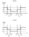
- FIG. 3C is a diagram illustrating transition of wireless transfer capacity to be changed depending on the time and the reception electric field in the exemplary embodiment 2.
- FIG. 3D is a diagram illustrating transition of a transfer band of a packet signal to be changed depending on the time and the reception electric field in the exemplary embodiment 2.
- FIG. 4 is a diagram illustrating an example of relationship of reception electric field information (X), the modulation scheme, the wireless transfer capacity, and the packet transfer band in the exemplary embodiment 2.
- FIG. 1 is a block diagram illustrating one exemplary embodiment of the invention.
- a wireless transfer device 100 includes a transmission process unit 11 , a wireless transceiver unit 12 , a transfer band control unit 13 , and a modulation scheme control unit 14 .
- the wireless transfer device 100 is connected to a wireless transfer path 3 .
- the transfer process unit 11 reads a packet signal from a high priority buffer 22 and a low priority buffer 23 , and outputs to the wireless transceiver unit 12 . At this time, the transmission process unit 11 controls a transfer band of the packet signal to be outputted to the wireless transceiver unit 12 on the basis of a transfer band control signal received from the transfer band control unit 13 .
- the wireless transceiver unit 12 converts the packet signal received from the transmission process unit 11 into a wireless transfer signal and outputs to the wireless transfer path 3 .
- the wireless transceiver unit 12 acquires communication quality information of the wireless transfer path 3 .
- a reception electric field level is used as the communication quality information.
- the wireless transceiver unit 12 acquires a reception electric field level of a wireless signal used for decision of line quality, generates reception electric field information, and informs the transfer band control unit 13 and the modulation scheme control unit 14 . Further, the wireless transceiver unit 12 controls a modulation scheme and wireless transfer capacity of the wireless transfer path 3 on the basis of modulation scheme information received from the modulation scheme control unit 14 .
- the wireless transceiver unit 12 extracts a packet signal from a wireless transfer signal received from another wireless transfer device (not shown) which is in a communication state with a wireless transfer device 200 via the wireless transfer path 3 .
- the transfer band control unit 13 controls a transfer band of a packet signal which can be secured in the wireless transfer path on the basis of the reception electric field information informed from the wireless transceiver unit 12 . Specifically, the transfer band control unit 13 compares the reception electric field level identified by the reception electric field information with a predetermined band control threshold value, generates the transfer band control signal on the basis of a result of the comparison, and outputs to the transmission process unit 11 .
- the modulation scheme control unit 14 generates the modulation scheme information by selecting a modulation scheme for maintaining the line quality of the wireless transfer path at a predetermined level, on the basis of the reception electric field information informed from the wireless transceiver unit 12 , and outputs to the wireless transceiver unit 12 .
- the modulation scheme control unit 14 compares the reception electric field level identified by the reception electric field with a predetermined modulation control threshold value, generates the modulation control signal by selecting the modulation scheme on the basis of the result of the comparison, and outputs to the wireless transceiver unit 12 .
- the band control threshold value used in the transfer band control unit 13 is different from the modulation control threshold value used in the modulation scheme control unit 14 .
- the band control threshold value and the modulation control threshold value are set so that transfer band reduction control is carried out prior to reduction of the wireless transfer capacity by modulation control. By carrying out such control, loss of the packet signal and transient fluctuation of transfer delay time are avoided.
- FIG. 2 is a block diagram illustrating one exemplary embodiment of the invention.
- the wireless transfer device 200 with an adaptive modulation function is connected to a wired transfer path 2 and the wireless transfer path 3 .
- the wireless transfer device 200 includes a priority decision circuit 21 , the high priority buffer 22 , the low priority buffer 23 , a transmission circuit 24 , a wireless transceiver circuit 25 , a transfer band control circuit 26 , and a modulation scheme control circuit 27 .
- the priority decision circuit 21 decides upon transfer priority of a packet signal received from the wired transfer path 2 on the basis of a predetermined priority decision condition.
- the priority decision circuit 21 outputs a packet signal with high transfer priority to the high priority buffer 22 , and outputs a packet signal with low transfer priority to the low priority buffer 23 .
- address information, a priority identifier, and the like, described in the packet signal can be employed.
- the high priority buffer 22 and the low priority buffer 23 temporarily store the packet signal received via the priority decision circuit 21 .
- the transmission circuit 24 controls the transfer band of the packet signal to be outputted to the wireless transceiver circuit 25 on the basis of the transfer band control signal received from the transfer band control circuit 26 .
- the transmission circuit 24 reads the packet signal from the high priority buffer 22 and the low priority buffer 23 , and outputs to the wireless transceiver circuit 25 .
- the wireless transceiver circuit 25 converts the packet signal received from the transmission circuit 24 into a wireless transfer signal and outputs to the wireless transfer path 3 .
- the wireless transceiver circuit 25 acquires communication quality information of the wireless transfer path 3 .
- the wireless transceiver circuit 25 acquires a reception electric field level of a wireless signal used for decision of line quality to generate reception electric field information and informs the transfer band control circuit 26 and the modulation scheme control circuit 27 .
- the wireless transceiver circuit 25 extracts the packet signal from the wireless transfer signal received, via the wireless transfer path 3 , from a wireless transfer device (not shown) opposite to the wireless transfer device 200 and outputs to the wired transfer path 2 .
- the wireless transceiver circuit 25 controls the modulation scheme and the wireless transfer capacity of the wireless transfer path 3 on the basis of modulation scheme information received from the modulation scheme control circuit 27 .
- the transfer band control circuit 26 controls a transfer band of a packet signal which can be secured in the wireless transfer path on the basis of the reception electric field information received from the wireless transceiver unit 25 . Specifically, the transfer band control circuit 26 generates the transfer band control signal on the basis of a result of the decision on the reception electric field information and outputs to the transmission circuit 24 . In other words, the transfer band control circuit 26 generates the transfer band control signal on the basis of the relationship between the reception electric field level identified by the reception electric field information and a predetermined band control threshold value, and outputs the transfer band control signal to the transmission circuit 24 .
- the modulation scheme control circuit 27 receives the reception electric field information from the wireless transceiver circuit 25 and monitors.
- the modulation scheme control circuit 27 selects a modulation scheme in which line quality of the wireless transfer path is maintained at a predetermined constant level, generates modulation scheme information, and outputs to the wireless transceiver circuit 25 .
- the modulation scheme control circuit 27 selects a modulation scheme on the basis of the relationship between the reception electric field level identified by the reception electric field information and a predetermined modulation control threshold value, generates modulation scheme information, and outputs to the wireless transceiver circuit 25 .
- FIG. 3 shows examples of graphs illustrating relations between the reception electric field level of wireless signal in wireless transfer path 3 and the modulation scheme, the wireless transfer capacity, and the transfer band of the packet signal.
- Times t11, t12, t21, t22, t31, t32, t41, t42 in FIG. 3A to FIG. 3D are times common to the same sighs one another.
- Reception electric field levels th11, th21 are the band control threshold values.
- Reception electric field levels th12, th22 are the modulation control threshold values.
- FIG. 3A is a diagram illustrating transition of a time and the reception electric field level, and one example in which the reception electric field level changes with elapse of time. It is shown, in the reception electric field levels th11 and th22, th11 is a higher reception electric field level and in a state in which higher line quality can be maintained.
- FIG. 3B shows transition of a time and the modulation scheme, and it is shown, in modulation schemes m3 and m1, m3 selects a modulation scheme with more multi-values.
- FIG. 3C shows transition of a time and the wireless transfer capacity, the wireless transfer capacity conjugates and changes depending on change of the modulation scheme of FIG. 3B . It is shown, in transfer capacity c3 and c1, c3 is larger wireless transfer capacity.
- FIG. 3D shows transition of a time and the transfer band of the packet signal, and it is shown, in packet transfer bands pc3 and pc1, pc3 secures a band which can transfers more packet signals.
- FIG. 4 shows one example, which is shown in FIG. 3 , on the relationship between the reception electric field information (X) outputted by the wireless transceiver circuit 25 and the modulation scheme, the wireless transfer capacity and the packet transfer band at the time, as a table.
- a condition (a) of FIG. 4 shows, for example, if the reception electric field information (X) is larger than the reception electric field level th11, m3, c3, and pc3 are selected as the modulation scheme, the wireless transfer capacity, and the packet transfer band, respectively.
- an operation which is carried out when the reception electric field level of the wireless transfer path 3 is decreased from a state in which the reception electric field level of the wireless transfer path 3 is higher than th11 of FIG. 3A to a middle-level between th12 and th21 through th12 is explained in detail using FIG. 2 to FIG. 4 .
- the wireless transceiver circuit 25 monitors the reception electric field level of the wireless transfer path 3 which changes as time passes and generates the reception electric field information (X), and successively informs the transfer band control circuit 26 , and the modulation scheme control circuit 27 .
- the transfer band control circuit 26 monitors the reception electric field information (X) received from the wireless transceiver circuit 25 . When detecting the electric field level becomes th11 at the time t11 of FIG. 3 , the transfer band control circuit 26 decides that a situation which corresponds to the condition (a) of FIG. 4 shifts to the condition (b) of FIG. 4 , generates the transfer band control signal to decrease the packet transfer band from pc3 to pc2, and informs the transmission circuit 24 .
- the transmission circuit 24 receives the transfer band control signal, adjusts an amount of the packet signals to be read from the high priority buffer 22 and the low priority buffer 23 so that the transfer band of the packet signal outputted to the wireless transceiver circuit 25 becomes pc2 of FIG. 3D or less, and outputs the packet signal to the wireless transceiver circuit 25 .
- the packet transfer band indicated by the transfer band control signal changes from pc3 to pc2
- the packet signal which is currently outputted to the wireless transceiver circuit 25 is transmitted without delay, and suppressing control on the transfer band is carried out.
- the modulation scheme control circuit 27 monitors the reception electric field information (X) received from the wireless transceiver circuit 25 , and decides that the situation which corresponds to the condition (a) of FIG. 4 shifts to the condition (b) of FIG. 4 , when detecting that the reception electric field becomes th11 at the time t11 of FIG. 3 , the modulation scheme to be selected is not changed in the condition (a) and the condition (b) of FIG. 4 , as shown in the graph of FIG. 3B , the modulation scheme m3 is maintained.
- the transfer band control circuit 26 and the modulation scheme control circuit 27 detect that the reception electric field level becomes th12 at the time t12 of FIG. 3 , from the reception electric field information (X) received from the wireless transceiver circuit 25 , and decide that the situation which corresponds to the condition (b) of FIG. 4 shifts to the condition (c) of FIG. 4 .
- the modulation scheme control circuit 27 since the modulation scheme to be selected on the condition (b) is different from the modulation scheme to be selected on the condition (c), the modulation scheme control circuit 27 generates a modulation scheme control signal to convert the modulation scheme from m3 to m2 and informs the wireless transceiver circuit 25 .
- the wireless transceiver circuit 25 changes the modulation scheme of the wireless transfer path from m3 to m2 on the basis of the modulation scheme control signal, and the wireless transfer capacity is reduced from c3 to c2 as shown in FIG. 3C therewith. Since the packet transfer band is already reduced to pc2 at the time t12, the packet signal received from the transmission circuit 24 is not influenced by reduction of the wireless transfer capacity from c3 to c2.
- the wireless transfer capacity and the transfer band of the packet signal are controlled so that the wireless transfer capacity is reduced, the reduction control of the transfer band of the packet signal to be transmitted to the wireless transfer path can be carried out prior to the reduction control of the wireless transfer capacity.
- the wireless transfer capacity and the transfer band of the packet signal are controlled so that the wireless transfer capacity is enlarged, enlargement control of the wireless transfer capacity can be carried out prior to expansion control of the transfer band of the packet signal. Therefore, loss of the packet signal with high priority and transient fluctuation of the transfer delay time can be avoided by change of the wireless transfer capacity with modulation scheme changeover.
- the wireless transfer device related to the exemplary embodiments of the invention may not necessarily be a device connected to other devices using a cable, and sound inputting means and data inputting means may be included in the wireless transfer device.
- the packet signal received from the wired transmission path is divided to two priority levels via the priority decision circuit 21 to be stored in the high priority buffer 22 and the low priority buffer 23 .
- division of the priority levels may not be two.
- the electric field level of the wireless signal is used for decision of the line quality of the wireless transfer path.
- the decision scheme of the line quality is not limited to the method, for example, a bit error rate of a wireless line or a SN ratio (Signal Noise Ratio) may be used.
- This invention can be used as a communication device for infrastructure used by a communication operator, and the like, in particular a fixed wireless transfer device using a microwave or millimeter wave.
Abstract
A wireless transfer device (100) is provided with: a transfer band control unit (13) for deciding upon a transfer band, on the basis of the result of a comparison of communication quality information pertaining to wireless communication, and a predetermined band control threshold value; a modulation scheme control unit (14) for deciding on a modulation scheme, on the basis of the result of a comparison of communication quality information and a predetermined modulation control threshold value; a transmission process unit (11) for controlling the transfer band for packet signals on the basis of the transfer band decided upon by the transfer band control unit (13), and outputting packet signals; and a wireless transceiver unit (12), for performing a modulation process on the packet signals output by the transmission process unit (11), doing so on the basis of the modulation scheme decided upon by the modulation scheme control unit (14). The band control threshold value and the modulation control threshold value are different values. In so doing, loss of high-priority packet signals, as well as transient fluctuations of transfer delay time, are avoided.
Description
This application is a National Stage Entry of International Application No. PCT/JP2013/004159, filed Jul. 4, 2013, which claims priority from Japanese Patent Application No. 2012-156324, filed Jul. 12, 2012. The entire contents of the above-referenced applications are expressly incorporated herein by reference.
The invention relates to a wireless transfer device and a method for control of wireless transfer band.
A wireless transfer device is known, in which a packet signal received from a wired transfer path is transmitted to an opposite station which is opposed via a wireless transfer path on a one-to-one basis and the opposite station outputs the packet signal to the wired transfer path again.
In a common technology on wireless transfer, if a multi-value number of a wireless modulation scheme is increased in the same wireless reception electric field level, wireless transfer capacity is increased and error tolerance of the wireless transfer path is deteriorated. On the contrary, if the multi-value number of the modulation scheme is decreased in the same wireless reception electric field level, the wireless transfer capacity is reduced and high error tolerance can be secured. Namely, if the multi-value number of the wireless modulation scheme is decreased in a situation in which the reception electric field level is reduced, though the wireless transfer capacity is reduced, high error tolerance can be obtained and line quality can be kept.
Generally, transmission capacity of the wireless transfer path tends to be small compared with the wired transfer path. However, since traffic is rapidly increased with recent rapid expansion of a mobile phone network and increase of data communication use, it is strongly desired to secure large transfer capacity in the wireless transfer path.
As one of techniques to secure larger transfer capacity of the wireless transfer path, an adaptive modulation function is known. When the multi-value number of the wireless modulation scheme is increased, compared with a normal operation condition, in a state in which the wireless reception electric field level is high and the line quality is high, larger transfer capacity can be acquired by using a wireless transfer device with the adaptive modulation function.
However, since the wireless transfer capacity which is used with modulation scheme changeover changes, the wireless transfer device with the adaptive modulation function needs to carry out suppression control of an amount of traffic to be sent to the wireless transfer path by following the change. If suppression control of the wireless transfer capacity and the amount of traffic is concurrently carried out when the control is carried out, traffic loss in transferring traffic and fluctuation of transfer delay time due to influence of transient buffering control, and the like, may occur.
Accordingly, in the wireless transfer device which transfers highly important traffic in which it is desirable not to generate traffic loss and fluctuation of transfer delay time, the problem is required to be solved.
Various proposals have been made, on a method for securing a reception electric field margin for maintaining a line by using the adaptive modulation function controlling the wireless modulation scheme, and for maintaining a transfer function of important traffic when the line quality of the wireless transfer path.
For example, Patent Literature 1 discloses a method for monitoring the wireless transfer capacity and controlling a signal band to be transmitted to the wireless transfer path depending on change of the wireless transfer capacity, in the system in which the transfer capacity of the wireless transfer path on the basis of the adaptive modulation control. By carrying out the method, unnecessary traffic congestion situation can be avoided and transfer rate and transfer quality of an important traffic can be maintained.
PTL 1: Japanese Patent Application Laid-Open No. 2011-239322
However, in a common method for maintaining transfer rate and transfer quality of an important traffic, after wireless transfer capacity changes, a transfer band of a packet signal transmitted to a wireless transfer path is controlled depending on the change. Therefore, when adaptive modulation control is carried out so that the wireless transfer capacity is reduced, an operation for reducing the transfer band of the packet signal to be transmitted late to the wireless transfer path is carried out with respect to reduction control of the wireless transfer capacity, a situation in which the transfer band of the packet signal excesses the wireless transfer capacity temporarily occurs. In such case, problems exist, in which a high priority packet is lost and fluctuation of transfer delay time occurs.
A wireless transfer device of the invention is a wireless transfer device for controlling a wireless modulation scheme and a transfer band of a packet signal, which includes a transfer band control unit which decides upon the transfer band on the basis of a result of a comparison of communication quality information of wireless communication, and a predetermined band control threshold value, a modulation scheme control unit which decides on a modulation scheme on the basis of a result of a comparison of the communication quality information and a predetermined modulation control threshold value, a transmission process unit which controls a transfer band for a packet signal on the basis of the transfer band decided upon by the transfer band control unit, and outputs the packet signal, and a wireless transceiver unit which performs a modulation process on the packet signal output by the transmission process unit, on the basis of the modulation scheme decided upon by the modulation scheme control unit, wherein the band control threshold value and the modulation control threshold value are different values.
A method for control of wireless transfer band of the invention is a method for acquiring communication quality information of wireless communication, and deciding upon a transfer band and a modulation scheme, on the basis of the acquired communication quality information, and includes deciding upon the transfer band and the modulation scheme so that changeover of the transfer band is carried out prior to changeover of the modulation scheme while communication quality is deteriorated.
Loss of the high priority packet and transient fluctuation of transfer delay time are avoided.
By referring to drawings, an exemplary embodiment of the invention is explained. FIG. 1 is a block diagram illustrating one exemplary embodiment of the invention.
A wireless transfer device 100 includes a transmission process unit 11, a wireless transceiver unit 12, a transfer band control unit 13, and a modulation scheme control unit 14. The wireless transfer device 100 is connected to a wireless transfer path 3.
The transfer process unit 11 reads a packet signal from a high priority buffer 22 and a low priority buffer 23, and outputs to the wireless transceiver unit 12. At this time, the transmission process unit 11 controls a transfer band of the packet signal to be outputted to the wireless transceiver unit 12 on the basis of a transfer band control signal received from the transfer band control unit 13.
The wireless transceiver unit 12 converts the packet signal received from the transmission process unit 11 into a wireless transfer signal and outputs to the wireless transfer path 3. The wireless transceiver unit 12 acquires communication quality information of the wireless transfer path 3. In explanations below, a reception electric field level is used as the communication quality information. The wireless transceiver unit 12 acquires a reception electric field level of a wireless signal used for decision of line quality, generates reception electric field information, and informs the transfer band control unit 13 and the modulation scheme control unit 14. Further, the wireless transceiver unit 12 controls a modulation scheme and wireless transfer capacity of the wireless transfer path 3 on the basis of modulation scheme information received from the modulation scheme control unit 14. The wireless transceiver unit 12 extracts a packet signal from a wireless transfer signal received from another wireless transfer device (not shown) which is in a communication state with a wireless transfer device 200 via the wireless transfer path 3.
The transfer band control unit 13 controls a transfer band of a packet signal which can be secured in the wireless transfer path on the basis of the reception electric field information informed from the wireless transceiver unit 12. Specifically, the transfer band control unit 13 compares the reception electric field level identified by the reception electric field information with a predetermined band control threshold value, generates the transfer band control signal on the basis of a result of the comparison, and outputs to the transmission process unit 11.
The modulation scheme control unit 14 generates the modulation scheme information by selecting a modulation scheme for maintaining the line quality of the wireless transfer path at a predetermined level, on the basis of the reception electric field information informed from the wireless transceiver unit 12, and outputs to the wireless transceiver unit 12. Specifically, the modulation scheme control unit 14 compares the reception electric field level identified by the reception electric field with a predetermined modulation control threshold value, generates the modulation control signal by selecting the modulation scheme on the basis of the result of the comparison, and outputs to the wireless transceiver unit 12.
In the exemplary embodiment of the invention, the band control threshold value used in the transfer band control unit 13 is different from the modulation control threshold value used in the modulation scheme control unit 14. Specifically, when the reception electric field level is deteriorated, that is, when the communication quality is deteriorated, the band control threshold value and the modulation control threshold value are set so that transfer band reduction control is carried out prior to reduction of the wireless transfer capacity by modulation control. By carrying out such control, loss of the packet signal and transient fluctuation of transfer delay time are avoided.
The priority decision circuit 21 decides upon transfer priority of a packet signal received from the wired transfer path 2 on the basis of a predetermined priority decision condition. The priority decision circuit 21 outputs a packet signal with high transfer priority to the high priority buffer 22, and outputs a packet signal with low transfer priority to the low priority buffer 23. As the priority decision condition by the priority decision circuit 21, address information, a priority identifier, and the like, described in the packet signal can be employed.
The high priority buffer 22 and the low priority buffer 23 temporarily store the packet signal received via the priority decision circuit 21.
The transmission circuit 24 controls the transfer band of the packet signal to be outputted to the wireless transceiver circuit 25 on the basis of the transfer band control signal received from the transfer band control circuit 26. The transmission circuit 24 reads the packet signal from the high priority buffer 22 and the low priority buffer 23, and outputs to the wireless transceiver circuit 25.
The wireless transceiver circuit 25 converts the packet signal received from the transmission circuit 24 into a wireless transfer signal and outputs to the wireless transfer path 3. The wireless transceiver circuit 25 acquires communication quality information of the wireless transfer path 3. Specifically, the wireless transceiver circuit 25 acquires a reception electric field level of a wireless signal used for decision of line quality to generate reception electric field information and informs the transfer band control circuit 26 and the modulation scheme control circuit 27. The wireless transceiver circuit 25 extracts the packet signal from the wireless transfer signal received, via the wireless transfer path 3, from a wireless transfer device (not shown) opposite to the wireless transfer device 200 and outputs to the wired transfer path 2. The wireless transceiver circuit 25 controls the modulation scheme and the wireless transfer capacity of the wireless transfer path 3 on the basis of modulation scheme information received from the modulation scheme control circuit 27.
The transfer band control circuit 26 controls a transfer band of a packet signal which can be secured in the wireless transfer path on the basis of the reception electric field information received from the wireless transceiver unit 25. Specifically, the transfer band control circuit 26 generates the transfer band control signal on the basis of a result of the decision on the reception electric field information and outputs to the transmission circuit 24. In other words, the transfer band control circuit 26 generates the transfer band control signal on the basis of the relationship between the reception electric field level identified by the reception electric field information and a predetermined band control threshold value, and outputs the transfer band control signal to the transmission circuit 24.
The modulation scheme control circuit 27 receives the reception electric field information from the wireless transceiver circuit 25 and monitors. The modulation scheme control circuit 27 selects a modulation scheme in which line quality of the wireless transfer path is maintained at a predetermined constant level, generates modulation scheme information, and outputs to the wireless transceiver circuit 25. In other words, the modulation scheme control circuit 27 selects a modulation scheme on the basis of the relationship between the reception electric field level identified by the reception electric field information and a predetermined modulation control threshold value, generates modulation scheme information, and outputs to the wireless transceiver circuit 25.
Next, operations in which the wireless transceiver circuit 25, the transfer band control circuit 26, and the modulation scheme control circuit 27 control a modulation scheme, wireless transfer capacity, and a transfer band of a packet signal, depending on a reception electric field level of a wireless signal in the wireless transfer path 3 are described in detail using FIG. 3 and FIG. 4 .
Further as one example of an operation of the invention, an operation which is carried out when the reception electric field level of the wireless transfer path 3 is decreased from a state in which the reception electric field level of the wireless transfer path 3 is higher than th11 of FIG. 3A to a middle-level between th12 and th21 through th12 is explained in detail using FIG. 2 to FIG. 4 .
The wireless transceiver circuit 25 monitors the reception electric field level of the wireless transfer path 3 which changes as time passes and generates the reception electric field information (X), and successively informs the transfer band control circuit 26, and the modulation scheme control circuit 27.
The transfer band control circuit 26 monitors the reception electric field information (X) received from the wireless transceiver circuit 25. When detecting the electric field level becomes th11 at the time t11 of FIG. 3 , the transfer band control circuit 26 decides that a situation which corresponds to the condition (a) of FIG. 4 shifts to the condition (b) of FIG. 4 , generates the transfer band control signal to decrease the packet transfer band from pc3 to pc2, and informs the transmission circuit 24.
The transmission circuit 24 receives the transfer band control signal, adjusts an amount of the packet signals to be read from the high priority buffer 22 and the low priority buffer 23 so that the transfer band of the packet signal outputted to the wireless transceiver circuit 25 becomes pc2 of FIG. 3D or less, and outputs the packet signal to the wireless transceiver circuit 25. At this time, when it is detected that the packet transfer band indicated by the transfer band control signal changes from pc3 to pc2, the packet signal which is currently outputted to the wireless transceiver circuit 25 is transmitted without delay, and suppressing control on the transfer band is carried out.
On the contrary, while the modulation scheme control circuit 27 monitors the reception electric field information (X) received from the wireless transceiver circuit 25, and decides that the situation which corresponds to the condition (a) of FIG. 4 shifts to the condition (b) of FIG. 4 , when detecting that the reception electric field becomes th11 at the time t11 of FIG. 3 , the modulation scheme to be selected is not changed in the condition (a) and the condition (b) of FIG. 4 , as shown in the graph of FIG. 3B , the modulation scheme m3 is maintained.
Further, when time passes to be at time t12, the transfer band control circuit 26 and the modulation scheme control circuit 27 detect that the reception electric field level becomes th12 at the time t12 of FIG. 3 , from the reception electric field information (X) received from the wireless transceiver circuit 25, and decide that the situation which corresponds to the condition (b) of FIG. 4 shifts to the condition (c) of FIG. 4 .
At this time, though the transfer band control signal generated by the transfer band control circuit 26 does not change in the situation of the packet transfer band pc2, since the modulation scheme to be selected on the condition (b) is different from the modulation scheme to be selected on the condition (c), the modulation scheme control circuit 27 generates a modulation scheme control signal to convert the modulation scheme from m3 to m2 and informs the wireless transceiver circuit 25.
The wireless transceiver circuit 25 changes the modulation scheme of the wireless transfer path from m3 to m2 on the basis of the modulation scheme control signal, and the wireless transfer capacity is reduced from c3 to c2 as shown in FIG. 3C therewith. Since the packet transfer band is already reduced to pc2 at the time t12, the packet signal received from the transmission circuit 24 is not influenced by reduction of the wireless transfer capacity from c3 to c2.
As described above, by carrying out reduction control of the packet transfer band prior to reduction of the wireless transfer capacity by changeover of the modulation scheme in the situation in which the reception electric field level of the wireless transfer path 3 is decreased, by making a difference between the modulation control threshold value as the standard for changeover of the modulation scheme and the band control threshold value as the standard for changeover of the transfer band of the packet signal, modulation scheme changeover by the adaptive modulation without affecting a transferring packet signal and the reduction control of the wireless transfer capacity therewith can be carried out.
Thereby when the reception electric field level of the wireless transfer path is lowered and the modulation scheme of the wireless transfer path, the wireless transfer capacity and the transfer band of the packet signal are controlled so that the wireless transfer capacity is reduced, the reduction control of the transfer band of the packet signal to be transmitted to the wireless transfer path can be carried out prior to the reduction control of the wireless transfer capacity. When the reception electric field level of the wireless transfer path is improved, and the modulation scheme of the wireless transfer path, the wireless transfer capacity and the transfer band of the packet signal are controlled so that the wireless transfer capacity is enlarged, enlargement control of the wireless transfer capacity can be carried out prior to expansion control of the transfer band of the packet signal. Therefore, loss of the packet signal with high priority and transient fluctuation of the transfer delay time can be avoided by change of the wireless transfer capacity with modulation scheme changeover.
The invention is not limited to the above described exemplary embodiments, and various changes can be made within the scope of the invention.
For example, the wireless transfer device related to the exemplary embodiments of the invention may not necessarily be a device connected to other devices using a cable, and sound inputting means and data inputting means may be included in the wireless transfer device.
In the exemplary embodiment of the invention shown in FIG. 2 , the packet signal received from the wired transmission path is divided to two priority levels via the priority decision circuit 21 to be stored in the high priority buffer 22 and the low priority buffer 23. However division of the priority levels may not be two.
In the exemplary embodiment of the invention shown in FIG. 2 , the electric field level of the wireless signal is used for decision of the line quality of the wireless transfer path. The decision scheme of the line quality is not limited to the method, for example, a bit error rate of a wireless line or a SN ratio (Signal Noise Ratio) may be used.
This application is based upon and claims the benefit of priority from Japanese Patent Application No. 2012-156324, filed on Jul. 12, 2012, the disclosure of which is incorporated herein in its entirety by reference.
This invention can be used as a communication device for infrastructure used by a communication operator, and the like, in particular a fixed wireless transfer device using a microwave or millimeter wave.
- 2 wired transfer path
- 3 wireless transfer path
- 11 transmission process unit
- 12 wireless transceiver unit
- 13 transfer band control unit
- 14 modulation scheme control unit
- 21 priority decision circuit
- 22 high priority buffer
- 23 low priority buffer
- 24 transmission circuit
- 25 wireless transceiver circuit
- 26 transfer band control circuit
- 27 modulation scheme control circuit
- 100 wireless transfer device
- 200 wireless transfer device
Claims (6)
1. A wireless transfer device, comprising:
a memory storing instructions;
one or more processors configured to execute the instructions to:
determine a transfer band for a packet signal transmitted to a wireless transfer path, on the basis of a result of a comparison of communication quality information pertaining to wireless communication, and a predetermined band control threshold value which is a standard for changing the transfer band;
determine a modulation scheme to be applied to the wireless transfer path, on the basis of a result of a comparison of the communication quality information and a predetermined modulation control threshold value which is a standard for changing the modulation scheme;
secure the determined transfer band in the wireless transfer path, and output the packet signal; and
perform a modulation process on the packet signal, on the basis of the determined modulation scheme,
wherein the band control threshold value and the modulation control threshold value are set to be different values, to create a time lag between an operation for changing the transfer band and an operation for changing wireless transfer capacity of the wireless transfer path, the wireless transfer capacity being changed in conjunction with the changing of the modulation scheme.
2. The wireless transfer device of claim 1 , wherein the band control threshold value is set to be larger than the modulation control threshold value so that: the operation for changing the transfer band is carried out prior to the operation for changing the modulation scheme when communication quality of the wireless transfer path is deteriorated, and the operation for changing the modulation scheme is carried out prior to the operation for changing the transfer band when the communication quality of the wireless transfer path is improved.
3. The wireless transfer device of claim 1 , wherein the communication quality information on the wireless communication includes at least one of an electric field level of the wireless communication, a bit error rate of a wireless line, or an SN ratio (signal noise ratio).
4. A method for controlling a transfer band for a packet signal transmitted to a wireless transfer path and a modulation scheme to be applied to the wireless transfer path, the method comprising:
determining the transfer band, on the basis of a result of a comparison of communication quality information pertaining to wireless communication, and a predetermined band control threshold value which is a standard for changing the transfer band;
determining the modulation scheme, on the basis of a result of a comparison of the communication quality information and a predetermined modulation control threshold value which is a standard for changing the modulation scheme;
securing the determined transfer band in the wireless transfer path, and outputting the packet signal; and
performing a modulation process on the packet signal, on the basis of the determined modulation scheme,
wherein the band control threshold value and the modulation control threshold value are set to be different values, to create a time lag between an operation for changing the transfer band and an operation for changing wireless transfer capacity of the wireless transfer path, the wireless transfer capacity being changed in conjunction with the changing of the modulation scheme.
5. The method of claim 4 , wherein the band control threshold value is set to be larger than the modulation control threshold value so that: the operation for changing the transfer band is carried out prior to the operation for changing the modulation scheme when communication quality of the wireless transfer path is deteriorated, and the operation for changing the modulation scheme is carried out prior to the operation for changing the transfer band when the communication quality of the wireless transfer path is improved.
6. The method of claim 4 , wherein the communication quality information on the wireless communication includes at least one of an electric field level of the wireless communication, a bit error rate of a wireless line, or an SN ratio (signal noise ratio).
Applications Claiming Priority (3)
| Application Number | Priority Date | Filing Date | Title |
|---|---|---|---|
| JP2012-156324 | 2012-07-12 | ||
| JP2012156324 | 2012-07-12 | ||
| PCT/JP2013/004159 WO2014010209A1 (en) | 2012-07-12 | 2013-07-04 | Wireless transfer system, and method for control of wireless transfer band |
Publications (2)
| Publication Number | Publication Date |
|---|---|
| US20150172008A1 US20150172008A1 (en) | 2015-06-18 |
| US9571237B2 true US9571237B2 (en) | 2017-02-14 |
Family
ID=49915692
Family Applications (1)
| Application Number | Title | Priority Date | Filing Date |
|---|---|---|---|
| US14/413,914 Active 2033-08-28 US9571237B2 (en) | 2012-07-12 | 2013-07-04 | Wireless transfer device and method for control of wireless transfer band |
Country Status (4)
| Country | Link |
|---|---|
| US (1) | US9571237B2 (en) |
| EP (1) | EP2874364A4 (en) |
| IN (1) | IN2015DN00160A (en) |
| WO (1) | WO2014010209A1 (en) |
Citations (9)
| Publication number | Priority date | Publication date | Assignee | Title |
|---|---|---|---|---|
| US20030202478A1 (en) | 2002-04-24 | 2003-10-30 | Alok Saxena | System and method for channel assignment with adaptive modulation in wireless communications |
| US20050245258A1 (en) * | 2004-04-28 | 2005-11-03 | Classon Brian K | Method and apparatus for transmission and reception of narrowband signals within a wideband communication system |
| JP2006086626A (en) | 2004-09-14 | 2006-03-30 | Hitachi Kokusai Electric Inc | Packet wireless communication system |
| US20070121738A1 (en) * | 2003-09-30 | 2007-05-31 | Matsushita Electric Industrial Co., Ltd. | Transmission apparatus and peak suppression method |
| US20090239560A1 (en) | 2005-11-29 | 2009-09-24 | Kyocera Corporation | Wireless Base Station Device and Method for Controlling Wireless Base Station Device |
| WO2011074681A1 (en) | 2009-12-14 | 2011-06-23 | 日本電気株式会社 | Communication apparatus and communication control method |
| US20110249678A1 (en) | 2010-04-08 | 2011-10-13 | Hunt Technologies, Llc | Dynamic modulation selection |
| JP2011239322A (en) | 2010-05-13 | 2011-11-24 | Nec Corp | NETWORK REPEATER AND QoS CONTROL METHOD |
| JP2012064992A (en) | 2008-12-16 | 2012-03-29 | Nec Corp | Communication apparatus, data rate control method and communication system |
-
2013
- 2013-07-04 US US14/413,914 patent/US9571237B2/en active Active
- 2013-07-04 EP EP13817624.3A patent/EP2874364A4/en not_active Withdrawn
- 2013-07-04 WO PCT/JP2013/004159 patent/WO2014010209A1/en active Application Filing
-
2015
- 2015-01-07 IN IN160DEN2015 patent/IN2015DN00160A/en unknown
Patent Citations (10)
| Publication number | Priority date | Publication date | Assignee | Title |
|---|---|---|---|---|
| US20030202478A1 (en) | 2002-04-24 | 2003-10-30 | Alok Saxena | System and method for channel assignment with adaptive modulation in wireless communications |
| US20070121738A1 (en) * | 2003-09-30 | 2007-05-31 | Matsushita Electric Industrial Co., Ltd. | Transmission apparatus and peak suppression method |
| US20050245258A1 (en) * | 2004-04-28 | 2005-11-03 | Classon Brian K | Method and apparatus for transmission and reception of narrowband signals within a wideband communication system |
| JP2006086626A (en) | 2004-09-14 | 2006-03-30 | Hitachi Kokusai Electric Inc | Packet wireless communication system |
| US20090239560A1 (en) | 2005-11-29 | 2009-09-24 | Kyocera Corporation | Wireless Base Station Device and Method for Controlling Wireless Base Station Device |
| JP2012064992A (en) | 2008-12-16 | 2012-03-29 | Nec Corp | Communication apparatus, data rate control method and communication system |
| WO2011074681A1 (en) | 2009-12-14 | 2011-06-23 | 日本電気株式会社 | Communication apparatus and communication control method |
| US20120230190A1 (en) | 2009-12-14 | 2012-09-13 | Nec Corporation | Communication device and communication control method |
| US20110249678A1 (en) | 2010-04-08 | 2011-10-13 | Hunt Technologies, Llc | Dynamic modulation selection |
| JP2011239322A (en) | 2010-05-13 | 2011-11-24 | Nec Corp | NETWORK REPEATER AND QoS CONTROL METHOD |
Non-Patent Citations (2)
| Title |
|---|
| Extended European Search Report mailed Feb. 10, 2016 by the European Patent Office in counterpart European Patent Application No. 13817624.3. |
| International Search Report and Written Opinion mailed Aug. 6, 2013 in corresponding PCT International Application. |
Also Published As
| Publication number | Publication date |
|---|---|
| IN2015DN00160A (en) | 2015-06-12 |
| EP2874364A1 (en) | 2015-05-20 |
| WO2014010209A1 (en) | 2014-01-16 |
| EP2874364A4 (en) | 2016-03-09 |
| US20150172008A1 (en) | 2015-06-18 |
Similar Documents
| Publication | Publication Date | Title |
|---|---|---|
| KR100963660B1 (en) | Method, apparatus and computer program to dynamically adjust segmentation at a protocol layer, such as at the medium access controlMAC layer | |
| EP2728943A1 (en) | Wireless transmission system, wireless transmission device, wireless transmission method and computer-readable medium | |
| WO2009084182A1 (en) | Communication device and communication system | |
| KR20130028104A (en) | Mobile communication terminal | |
| JP6141053B2 (en) | Terminal device, communication system, information processing device, and communication program | |
| CN104969629A (en) | Method and device for adjusting sending power | |
| US11071112B2 (en) | Dynamically adjusting communication channel bandwidth | |
| US9571237B2 (en) | Wireless transfer device and method for control of wireless transfer band | |
| JP2011044817A (en) | Controller for communication system, control method and computer program | |
| JP2022530517A (en) | Transmission power determination method, equipment and communication equipment | |
| KR20180029514A (en) | Networlk device and control method thereof | |
| US8886133B2 (en) | Network station power adjustment apparatus and power adjustment method thereof | |
| EP4016966A1 (en) | Dynamic adaptation of time-aware communications in time-sensitive systems | |
| US10165568B2 (en) | Data communication apparatus, computer readable medium, and satellite communication system | |
| US10869226B2 (en) | Wireless communication apparatus, wireless communication system and wireless communication method | |
| CN112786062A (en) | Bandwidth adaptive network audio transmission method, device, medium and system | |
| CN107624259B (en) | Power control for energy efficient transmitter | |
| WO2010125820A1 (en) | Transmission device and transmission method | |
| JP2007306623A (en) | Wireless base station, mobile terminal, wireless communication system, and wireless communication method | |
| WO2018116965A1 (en) | Wireless communication device, wireless communication system, and wireless communication method | |
| JP5900458B2 (en) | Signal transmission system, receiver, transmitter, receiver control program, and signal transmission method | |
| KR100342633B1 (en) | Mobile communication system capable of reducing a traffic between a control station and base stations | |
| JP2011172162A (en) | Receiving apparatus, transmitting apparatus, communication system, communication method and program | |
| WO2021111903A1 (en) | Reception terminal and method | |
| JP2009303045A (en) | Wireless communication apparatus |
Legal Events
| Date | Code | Title | Description |
|---|---|---|---|
| AS | Assignment |
Owner name: NEC CORPORATION, JAPAN Free format text: ASSIGNMENT OF ASSIGNORS INTEREST;ASSIGNOR:SAITO, KAICHIRO;REEL/FRAME:034674/0927 Effective date: 20141208 |
|
| STCF | Information on status: patent grant |
Free format text: PATENTED CASE |
|
| MAFP | Maintenance fee payment |
Free format text: PAYMENT OF MAINTENANCE FEE, 4TH YEAR, LARGE ENTITY (ORIGINAL EVENT CODE: M1551); ENTITY STATUS OF PATENT OWNER: LARGE ENTITY Year of fee payment: 4 |