US9560638B2 - Short physical-layer control frames - Google Patents
Short physical-layer control frames Download PDFInfo
- Publication number
- US9560638B2 US9560638B2 US14/406,126 US201314406126A US9560638B2 US 9560638 B2 US9560638 B2 US 9560638B2 US 201314406126 A US201314406126 A US 201314406126A US 9560638 B2 US9560638 B2 US 9560638B2
- Authority
- US
- United States
- Prior art keywords
- control frame
- entity
- frame
- information relating
- layer
- Prior art date
- Legal status (The legal status is an assumption and is not a legal conclusion. Google has not performed a legal analysis and makes no representation as to the accuracy of the status listed.)
- Active, expires
Links
Images


Classifications
-
- H04W72/0406—
-
- H—ELECTRICITY
- H04—ELECTRIC COMMUNICATION TECHNIQUE
- H04W—WIRELESS COMMUNICATION NETWORKS
- H04W72/00—Local resource management
- H04W72/20—Control channels or signalling for resource management
-
- H—ELECTRICITY
- H04—ELECTRIC COMMUNICATION TECHNIQUE
- H04L—TRANSMISSION OF DIGITAL INFORMATION, e.g. TELEGRAPHIC COMMUNICATION
- H04L1/00—Arrangements for detecting or preventing errors in the information received
- H04L1/0078—Avoidance of errors by organising the transmitted data in a format specifically designed to deal with errors, e.g. location
- H04L1/0079—Formats for control data
-
- H—ELECTRICITY
- H04—ELECTRIC COMMUNICATION TECHNIQUE
- H04L—TRANSMISSION OF DIGITAL INFORMATION, e.g. TELEGRAPHIC COMMUNICATION
- H04L1/00—Arrangements for detecting or preventing errors in the information received
- H04L1/12—Arrangements for detecting or preventing errors in the information received by using return channel
- H04L1/16—Arrangements for detecting or preventing errors in the information received by using return channel in which the return channel carries supervisory signals, e.g. repetition request signals
- H04L1/1607—Details of the supervisory signal
- H04L1/1685—Details of the supervisory signal the supervisory signal being transmitted in response to a specific request, e.g. to a polling signal
-
- H—ELECTRICITY
- H04—ELECTRIC COMMUNICATION TECHNIQUE
- H04W—WIRELESS COMMUNICATION NETWORKS
- H04W84/00—Network topologies
- H04W84/02—Hierarchically pre-organised networks, e.g. paging networks, cellular networks, WLAN [Wireless Local Area Network] or WLL [Wireless Local Loop]
- H04W84/10—Small scale networks; Flat hierarchical networks
- H04W84/12—WLAN [Wireless Local Area Networks]
Definitions
- the field of the invention is that of communication systems using a radio, electrical or optical transmission channel, and more particularly that of the management of a channel using control frames, when said channel is shared between a plurality of transmitting or receiving entities.
- the transmission channel is a shared resource that is perturbed by interference between the various transmitting and receiving entities that share the channel, and by collisions between the various data frames passing through the channel.
- control frames are interchanged between the transmitting and receiving entities, before and after a data frame interchange.
- FIG. 1 illustrates the composition of a frame, taking as a basis the IEEE 802.11 (WiFi) standard example of a data frame DATA 1 and three control frames RTS 0 , CTS 0 and ACK 0 .
- Such frames comprise all of the following parts:
- the STF field is invariant and is used for time synchronization.
- the LTF field is used for frequency synchronization, and the SIG field is used for signaling data intended for the receiver.
- the fields and the data are modulated using OFDM (Orthogonal Frequency Division Multiplexing) modulation.
- OFDM Orthogonal Frequency Division Multiplexing
- the PLCP sublayer is part of the physical layer, which is the first layer and the lowest.
- the MAC sublayer is part of the data link layer, which is the second layer of the model.
- the PLCP sublayer of an entity On receiving a data or control frame, the PLCP sublayer of an entity first of all detects the frame beginning using the STF field. If the time synchronization is correct for a WiFi frame, the frame is demodulated, and the result is returned to the MAC sublayer.
- the MAC sublayer checks the integrity of the frame using the FCS field, and, depending on the result, it moreover checks if the frame is indeed intended for the entity, using the MAC header.
- the mechanism for generating a data frame or a control frame also requires interactions between the first two layers, the physical layer and the data link layer.
- a control frame of RTS (Request To Send) type is first of all transmitted by the transmitting entity. Said control frame is intended to reserve the channel for a determined duration.
- the receiving entity responds by transmitting a control frame of CTS (Clear To Send) type. This control frame is intended to confirm the reservation of the channel, for a corrected duration.
- the transmitting entity then transmits the data frame, to which the receiving entity responds with a control frame of ACK (ACKnowldgement) type.
- PSPOLL Power Save Polling
- SIFS Short Inter-Frame Sequence
- the data of a data frame are of variable size, ranging from approximately 100 bytes for voice over Internet protocol, or 127 bytes for data interchanged from machine to machine, to several kilobytes for video.
- the transmission of 100 bytes can take 40 ⁇ s, while transmission of a packet of 1500 bytes can take up to 2064 ⁇ s.
- All of the bytes making up the MAC part (header and data) are modulated at a speed optimized on the basis of the conditions of the transmission channel, for example at 36 Mbit/s for the 16QAM (16-state Quadrature Amplification Modulation) technique.
- the SIG field (24 bytes) is modulated at a speed lower than that for the MAC part, for example at 6 Mbit/s for the BPSK (Binary Phase Shift Keying) technique, which makes the SIG field more robust than the fields of the MAC layer.
- BPSK Binary Phase Shift Keying
- control frames are therefore a large share of the traffic, in relation to data frames, also known as “payload” frames. This is the case particularly with voice over IP traffic and data traffic between machines, where the bandwidth occupied by the control frames is a problem.
- the invention improves the situation by means of a method for the transmission of a control frame by a transmitting entity to a receiving entity, the control frame comprising a so-called first-layer header field, which is intended to transport information relating to a first layer, the method comprising a modulation step using a first modulation technique, and, prior to the modulation step, a step of insertion of information relating to a second layer into said first-layer header field.
- a second-layer header is no longer necessary in the control frame. This frees a first-layer header that is intended for processing the second-layer header. In relation to the prior art, this method therefore allows the length of the control frame to be shortened, and moreover allows the use of just a single modulation technique, rather than two (one per layer).
- the information relating to the MAC layer is transported in the MAC header.
- the information relating to the MAC layer is inserted into the SIG field. This firstly frees the MAC header, which is no longer inserted into the control frame, and secondly frees the original use of the SIG field.
- the occupation of the transmission channel by a WiFi control frame is in the order of 32 ⁇ s.
- this duration is in the order of 20 ⁇ s.
- control frame no longer comprises a field or header relating to the MAC layer, there is no need for any modulation using a modulation technique relating to this MAC layer. All that remains is the modulation of the SIG field using a modulation technique relating to the PLCP layer, which is more robust and less complex than the modulation technique relating to the MAC layer.
- a control frame is shorter and that the transmitting entity needs to implement only a single mode of modulation, the latter relating to the first layer, which happens to be the most robust. This allows a reduction in the bandwidth taken by the control frames in the data traffic, an increase in the transmission robustness thereof and a reduction in the number and complexity of the modulation operations in the transmitting entity.
- the inserted information relating to the second layer comprises at least one piece of information from a group comprising at least:
- an ACK control frame (so-called “acknowledgement” frame for WiFi) comprises, in its SIG field, not only the “ACK” type but also an identifier for the receiving entity for which the ACK frame is intended, but does not comprise an identifier for the transmitting entity, nor any duration information.
- the invention also concerns a method for the reception of a control frame by a receiving entity from a transmitting entity, the control frame comprising a header field that is intended to transport information relating to a first layer, the method comprising a demodulation step for said header field using a first modulation technique, and, following the demodulation step, an extraction step for extracting information relating to a second layer, from the demodulated header field.
- the information extracted in this way can be transmitted to the second layer, for example the MAC layer, so as to be processed therein as information relating to this layer.
- this method allows the use of just a single demodulation type when a control frame is received, rather than two. This allows a reduction in the number and complexity of the demodulation operations in the receiving entity.
- the extracted information is not transmitted to the second layer if no correspondence is detected between the identifier of the receiving entity and the extracted information.
- the processing of a control frame that is received by the receiving entity but that is not intended therefor stops at the first layer, for example the PLCP layer, without involving the second layer, for example the MAC layer. This gives rise to a saving in time and calculations for the receiving entity.
- the invention also concerns a method for the transmission of a data frame by a transmitting entity to a receiving entity, comprising, prior to a step of transmission of the data frame, the following steps:
- control frames For each transmitted data frame, at least two control frames are interchanged between the transmitting and receiving entities.
- the share of the control frames in relation to that of the data frames is large, particularly when the data frames are short. It will therefore be understood that, by virtue of the invention, the share taken by the volume of the control frames in the traffic generated by the transmission of data frames is decreased because the size of the control frames is decreased in relation to the prior art.
- the invention also concerns a method for the reception of a data frame by a receiving entity from a transmitting entity, comprising, following a step of reception of the data frame, a step of transmission of an acknowledgement control frame, which is intended to acknowledge to the transmitting entity the reception of the data frame, the acknowledgement control frame being transmitted in accordance with the method for the transmission of a control frame that has just been described.
- At least one control frame is transmitted.
- the share of the control frames in relation to that of the data frames is large, particularly when the data frames are short. It will therefore be understood that, by virtue of the invention, the share taken by the volume of the control frames in the traffic generated by the reception of data frames is decreased because the size of the control frames is decreased in relation to the prior art.
- the step of reception of a data frame is preceded by a step of transmission of a standby exit indication control frame, which is intended to inform the transmitting entity that the receiving entity has exited a standby mode and is ready to receive a data frame, the standby exit indication control frame being transmitted in accordance with the method for the transmission of a control frame that has just been described.
- this aspect allows a control frame of “PSPOLL” type to be taken into account.
- the invention also concerns a device for the transmission of a control frame by a transmitting entity to a receiving entity, the control frame comprising a header field that is intended to transport information relating to a first layer, said header field being modulated using a first modulation technique, the device comprising a unit for the insertion of information relating to a second layer, into the header field relating to the first layer.
- the invention also concerns a device for the reception of a control frame by a receiving entity from a transmitting entity, the control frame comprising a header field that is intended to transport information relating to a first layer, said header field being demodulated using a first modulation technique, the device comprising a unit for the extraction of information relating to a second layer, from the header field relating to the first layer.
- the invention also concerns a device for the transmission of a data frame by a transmitting entity to a receiving entity, comprising:
- the invention also concerns a device for the reception of a data frame by a receiving entity from a transmitting entity, comprising:
- the invention also concerns a control signal carrying a control frame that is transmitted by a transmitting entity and that is intended for a receiving entity, the control frame comprising a field relating to a first layer modulated using a modulation technique relating to the first layer, the field comprising information relating to a second layer.
- this signal according to the invention occupies less bandwidth because the information relating to the second layer is inserted not into a field relating to the second layer, but rather into a pre-existing field relating to the first layer, reuse of which to this end is permitted owing to the absence of a field relating to the second layer.
- the information relating to the second layer that is comprised in the signal comprises at least one piece of information from a group comprising at least:
- the signal may carry any one of the control frames that are necessary for the transport of a data frame between a transmitting entity and a receiving entity, including, inter alia, the channel reservation, channel reservation confirmation, acknowledgement or standby exit indication frames.
- the invention also concerns a transmitting entity connected to a communication network, comprising at least one device for the transmission of a data frame as described above.
- Such a transmitting entity is the access point or a station in a WiFi network, for example.
- the access point is a home or professional Internet access gateway, for example, and the station is a computer, a tablet, a telephone or a television signal decoder, for example.
- the invention also concerns a receiving entity connected to a communication network, comprising at least one device for the reception of a data frame as described above.
- Such a receiving entity is the access point or a station in a WiFi network, for example.
- the access point is a home or professional Internet access gateway, for example, and the station is a computer, a tablet, a telephone or a television signal decoder, for example.
- the invention likewise concerns a transmitting and receiving entity, comprising both a device for the transmission of a data frame as described above and a device for the reception of a data frame as described above.
- the invention also concerns a communication system, characterized in that it comprises at least one transmitting entity as described above and at least one receiving entity as described above.
- Such a system comprises the access point and the station(s) in a WiFi network, for example.
- the invention also concerns a computer program, comprising instructions for the implementation of the steps of the method for the transmission of a control frame as described above when this method is executed by a processor.
- the invention likewise concerns a recording medium for the program that has just been described, which is computer-readable, being able to use any programming language, and to be in the form of source code, object code or intermediate code between source code and object code, as in a partially compiled form, or in any other desirable form.
- the invention also concerns a computer program, comprising instructions for the implementation of the steps of the method for the reception of a control frame as described above when this method is executed by a processor.
- the invention likewise concerns a recording medium for the program that has just been described, which is computer-readable, being able to use any programming language, and to be in the form of source code, object code or intermediate code between source code and object code, as in a partially compiled form, or in any other desirable form.
- the invention also concerns a computer program, comprising instructions for the implementation of the steps of the method for the transmission of a data frame as described above when this method is executed by a processor.
- the invention likewise concerns a recording medium for the program that has just been described, which is computer-readable, being able to use any programming language, and to be in the form of source code, object code or intermediate code between source code and object code, as in a partially compiled form, or in any other desirable form.
- the invention also concerns a computer program, comprising instructions for the implementation of the steps of the method for the reception of a data frame as described above when this method is executed by a processor.
- the invention concerns a recording medium for the program that has just been described, which is computer-readable, being able to use any programming language, and to be in the form of source code, object code or intermediate code between source code and object code, as in a partially compiled form, or in any other desirable form.
- FIG. 1 shows the structure of a data frame and the structure of various control frames according to the prior art
- FIG. 2 shows the structure of a data frame and the structure of various control frames according to an embodiment of the invention
- FIGS. 3A to 3D show the structure of various control frames according to an embodiment of the invention in detail
- FIG. 4 shows the steps of the method for the transmission of a control frame according to an embodiment of the invention
- FIG. 5 shows the steps of the method for the reception of a control frame according to an embodiment of the invention
- FIG. 6 shows the steps of the method for the reception of a control frame according to another embodiment of the invention
- FIG. 7 shows a design example for a transmitting entity EE 1 , according to the invention.
- FIG. 8 shows a design example for a receiving entity ER 1 , according to the invention.
- FIG. 2 shows the structure of a data frame and the structure of various control frames, according to an embodiment of the invention.
- control frames and data frame remains unchanged in relation to the prior art and has been described with reference to FIG. 1 .
- the control frames RTS 1 , CTS 1 and ACK 1 , or channel reservation request, channel reservation confirmation and acknowledgement frames, contrary to the prior art, comprise neither a MAC header nor the following fields, FCS, tail and pad.
- the control frames according to the invention comprise the STF and LTF fields, which remain unchanged in relation to the prior art, and a modified SIG field. As illustrated in FIGS. 3A to 3D , the invention proposes unanticipated use of the SIG field by inserting into it information relating to the second layer (MAC), which is usually inserted into the MAC header.
- MAC second layer
- the modified SIG field Prior to the transmission of a control frame, the modified SIG field is modulated using a low-speed modulation technique that is specific to the first layer, for example BPSK.
- control frames While keeping the functionality of the control frames, not only are they shorter but it is no longer necessary to apply high-speed modulation to them that is specific to the MAC header, for example 16QAM.
- FIGS. 3A to 3D show the structure of various control frames according to one embodiment of the invention in detail.
- FIG. 3A illustrates the composition of a control frame of RTS type, that is to say a frame transmitted by an entity wishing to transmit a data frame to a receiving entity, which is intended to request the reservation of a communication channel for a certain duration between the two entities.
- the SIG′ field of a control frame of RTS type comprises, besides a PLCP type field (with the value RTS), a DUR field, a Partial RA field and a Partial TA field.
- FIG. 3B illustrates the composition of a control frame of CTS type, that is to say a frame transmitted by an entity that has previously received a control frame of RTS type, which is intended to confirm the reservation of a communication channel for a certain duration, the duration being corrected by this entity in order to take account of the duration that has elapsed since the reception of the control frame RTS.
- the SIG′′ field of a control frame of CTS type comprises, besides a PLCP type field (with the value CTS), a DUR field, and a Partial RA field.
- FIG. 3C illustrates the composition of a control frame of ACK type, that is to say a frame transmitted by an entity that has previously received a data frame, which is intended to confirm to the entity transmitting the data frame the correct reception of the data frame.
- the SIG′′′ field of a control frame of ACK type comprises, besides a PLCP type field (with the value ACK), a Partial RA field.
- FIG. 3D illustrates the composition of a control frame of PSPOLL type, that is to say a frame transmitted by an entity exiting a standby mode and wishing to indicate, to another entity that is capable of transmitting a data frame, that it is in a mode that allows it to receive a data frame.
- the SIG′′′′ field of a control frame of PSPOLL type comprises, besides a PLCP type field (with the value PSPOLL), a Partial RA field and a Partial TA field.
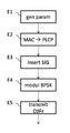
- FIG. 4 shows the steps of the method for the transmission of a control frame according to an embodiment of the invention.
- the method is presented on the basis of the example of the frame RTS 1 with reference to FIG. 2 .
- a step E 1 the entity EE 1 generates, on its MAC layer, the parameters characterizing the frame RTS 1 , that is to say:
- a step E 2 these parameters, which are generated by the MAC layer, are transferred to the PLCP layer of the entity EE 1 .
- the PLCP layer of the entity EE 1 inserts the parameters from the MAC layer into the SIG′ field of a control frame having, besides the SIG′ field, an STF field and an LTF field.
- the PLCP layer of the entity EE 1 applies modulation of BPSK type to the SIG′ field.
- the frame RTS 1 is now ready to be transmitted.
- the PLCP layer of the entity EE 1 transmits the frame RTS 1 .
- FIG. 5 shows the steps of the method for the reception of a control frame according to an embodiment of the invention.
- the method is presented on the basis of the example of the frame RTS 1 with reference to FIG. 2 .
- the PLCP layer of the entity ER 1 receives the frame RTS 1 and detects that it is composed of an STF field, an LTF field and an SIG′ field.
- a step R 2 the PLCP layer of the entity ER 1 demodulates the SIG′ field of the frame RTS 1 .
- a step R 3 the PLCP layer of the entity ER 1 extracts the following MAC layer parameters from the SIG′ field:
- a step R 4 these parameters are transferred from the PLCP layer to the MAC layer of the entity EE 1 .
- a step R 5 the parameters are processed on the MAC layer.
- the processing includes the decision to respond by a frame CTS 1 . This decision is followed by steps similar to steps E 1 to E 5 described above, leading to the transmission of the frame CTS 1 by ER 1 to EE 1 .
- FIG. 6 shows steps of the method for the reception of a control frame according to another embodiment of the invention.
- the PLCP layer checks that the simplified identifier of the receiving entity, Partial RA, extracted from the SIG′ field, actually corresponds to that of the entity ER 1 .
- step R 4 If correspondence exists, the following step continues to be step R 4 .
- the received control frame is ignored because it is not intended for the entity ER 1 , and steps R 4 and R 5 are not executed. This allows the fastest determination of the fact that the frame is not intended for ER 1 , without having to transmit the extracted parameters to the MAC layer so that the latter is able to arrive at the same conclusion. Thus, a saving in time and calculations is achieved.
- the transmitting entity EE 1 comprises at least:
- the device 300 for the transmission of a data frame comprises at least:
- the device 100 for the transmission of a control frame comprises a processing unit 130 that is equipped with a microprocessor for implementing the means constituting the invention as are described above.
- the device 100 comprises a unit 180 for inserting information relating to a second layer into a header field relating to a first layer.
- the insertion unit 180 is controlled by the microprocessor of the processing unit 130 .
- the device 100 comprises a memory 120 that stores a computer program 110 implementing the steps of the method for the transmission of a control frame.
- the code instructions of the computer program 110 are loaded into a RAM store, for example, before being executed by the processor of the processing unit 130 .
- the device 100 for the transmission of a control frame is capable of cooperating at least with the transmission module 370 and the modulator 360 .
- the insertion unit 180 inserts the parameters PLCP type, DUR, Partial RA and Partial TA into a SIG field of a control frame RTS.
- the processing unit 130 then instructs the modulator 360 to modulate the SIG field, and then the transmission module 370 to transmit the frame RTS.
- the device 200 for the reception of a control frame comprises a processing unit 230 equipped with a microprocessor for implementing the means constituting the invention as are described above.
- the device 200 comprises a unit 180 for the extraction of information relating to a second layer from a header field relating to a first layer.
- the extraction unit 280 is controlled by the microprocessor of the processing unit 230 .
- the device 200 comprises a memory 220 that stores a computer program 210 implementing the steps of the method for the reception of a control frame.
- the code instructions of the computer program 210 are loaded into a RAM store, for example, before being executed by the processor of the processing unit 230 .
- the device 200 for the reception of a control frame is capable of cooperating at least with the reception module 340 and the demodulator 350 .
- the processing unit 230 instructs the module 340 to send the demodulator 350 the SIG field of the frame so that the latter is demodulated. Then, under the control of the processing unit 230 , the extraction unit 280 extracts the parameters PLCP type, DUR, and Partial RA from the demodulated SIG field.
- the receiving entity ER 1 comprises at least:
- the device 400 for the transmission of a data frame comprises at least:
- an entity can be both a transmitting entity (EE 1 ) and a receiving entity (ER 1 ).
- E 1 transmitting entity
- ER 1 receiving entity
- the exemplary embodiments of the invention that have just been presented are just some of the embodiments that are conceivable. They show that the invention allows a reduction in the bandwidth taken by control frames in data traffic, an increase in the transmission robustness thereof and a reduction in the number and complexity of the modulation operations in the transmitting entity, and also in the number and complexity of the demodulation operations in the receiving entity.
Abstract
A method is provided for transmitting a control frame from a emitting entity to a receiving entity. The control frame includes what is called a “first layer” header field intended to convey information relating to a first layer. The method includes a modulation step employing a first modulation technique, and, before the modulation step, a step of inserting information relating to a second layer into the first layer header field.
Description
This Application is a Section 371 National Stage Application of International Application No. PCT/FR2013/051281, filed Jun. 5, 2013 and published as WO 2013/182812 A1 on Dec. 12, 2013, not in English, the contents of which are hereby incorporated by reference in their entirety.
The field of the invention is that of communication systems using a radio, electrical or optical transmission channel, and more particularly that of the management of a channel using control frames, when said channel is shared between a plurality of transmitting or receiving entities.
In radio communication systems, powerline communication and wireless optical communication, the transmission channel is a shared resource that is perturbed by interference between the various transmitting and receiving entities that share the channel, and by collisions between the various data frames passing through the channel. To make the data frame interchanges more reliable, so-called “control” frames are interchanged between the transmitting and receiving entities, before and after a data frame interchange.
The data frames and the control frames are in the same format. FIG. 1 illustrates the composition of a frame, taking as a basis the IEEE 802.11 (WiFi) standard example of a data frame DATA1 and three control frames RTS0, CTS0 and ACK0. Such frames comprise all of the following parts:
-
- a PLCP (Physical Layer Convergence Protocol) header, comprising the fields STF (Short Training Field), LTF (Long Training Field) and SIG (Signal Field),
- an MAC (Medium Access Control) header with a Frame Control field indicating the type of the frame (DATA for a data frame or ACK for an acknowledgement frame, for example), and one or more fields that may be, inter alia, a source MAC address field, a destination MAC address field, and/or a Duration field (duration of a frame interchange),
- the MAC data, which are absent if the frame is a control frame,
- and other fields such as FCS (Frame Check Sequence), tail, pad.
The STF field is invariant and is used for time synchronization. The LTF field is used for frequency synchronization, and the SIG field is used for signaling data intended for the receiver.
The fields and the data are modulated using OFDM (Orthogonal Frequency Division Multiplexing) modulation. A frame is represented as a succession of OFDM symbols.
In the seven-layer OSI (Open Systems Interconnection) communication model, which is used by local area networks based on the IEEE 802.11 standard, the PLCP sublayer is part of the physical layer, which is the first layer and the lowest. The MAC sublayer is part of the data link layer, which is the second layer of the model. On receiving a data or control frame, the PLCP sublayer of an entity first of all detects the frame beginning using the STF field. If the time synchronization is correct for a WiFi frame, the frame is demodulated, and the result is returned to the MAC sublayer. The MAC sublayer checks the integrity of the frame using the FCS field, and, depending on the result, it moreover checks if the frame is indeed intended for the entity, using the MAC header. Similarly, the mechanism for generating a data frame or a control frame also requires interactions between the first two layers, the physical layer and the data link layer.
To make the interchange of a data frame more reliable, a control frame of RTS (Request To Send) type is first of all transmitted by the transmitting entity. Said control frame is intended to reserve the channel for a determined duration. The receiving entity responds by transmitting a control frame of CTS (Clear To Send) type. This control frame is intended to confirm the reservation of the channel, for a corrected duration. The transmitting entity then transmits the data frame, to which the receiving entity responds with a control frame of ACK (ACKnowldgement) type.
There is likewise a control frame of PSPOLL (Power Save Polling) type, which is transmitted by a receiving entity when it exits a standby period, so as to signal to a transmitting entity that it is ready to receive a data frame. If the transmitting entity actually has a data frame to transmit to it, it does so. Otherwise, it transmits a control frame of ACK type to it.
The SIFS (Short Inter-Frame Sequence) period allows, for the entities concerned by the transmission, the time to pass from transmission mode to reception mode (and vice versa). This period is included in the calculation of the value of the Duration field of the MAC header, if need be.
The data of a data frame are of variable size, ranging from approximately 100 bytes for voice over Internet protocol, or 127 bytes for data interchanged from machine to machine, to several kilobytes for video. On the basis of the IEEE 802.11a standard, the transmission of 100 bytes can take 40 μs, while transmission of a packet of 1500 bytes can take up to 2064 μs. All of the bytes making up the MAC part (header and data) are modulated at a speed optimized on the basis of the conditions of the transmission channel, for example at 36 Mbit/s for the 16QAM (16-state Quadrature Amplification Modulation) technique.
The SIG field (24 bytes) is modulated at a speed lower than that for the MAC part, for example at 6 Mbit/s for the BPSK (Binary Phase Shift Keying) technique, which makes the SIG field more robust than the fields of the MAC layer. The reason is that the modulated signals have a different range depending on the speed used; the higher the speed, the shorter the range of the signal and the higher the risk of error on reception.
On the basis of the IEEE 802.11a standard, the occupation of the transmission channel by a control frame (with its 20-byte MAC header) is in the order of 32 μs. For data traffic in which relatively short data frames can take approximately 40 μs of channel occupation, control frames are therefore a large share of the traffic, in relation to data frames, also known as “payload” frames. This is the case particularly with voice over IP traffic and data traffic between machines, where the bandwidth occupied by the control frames is a problem.
Moreover, the presence of an MAC header modulated at a higher speed in relation to the rest of the control frame reduces the robustness thereof, and constitutes a complexity factor for the modulation and demodulation operations of the control frame. For transmitting or receiving entities with substantial power constraints, such as those involved in interchanges between machines, this complexity factor gives rise to a power consumption that is likewise a problem.
There is therefore a need for a solution that does not exhibit these disadvantages.
The invention improves the situation by means of a method for the transmission of a control frame by a transmitting entity to a receiving entity, the control frame comprising a so-called first-layer header field, which is intended to transport information relating to a first layer, the method comprising a modulation step using a first modulation technique, and, prior to the modulation step, a step of insertion of information relating to a second layer into said first-layer header field.
By virtue of the invention, a second-layer header is no longer necessary in the control frame. This frees a first-layer header that is intended for processing the second-layer header. In relation to the prior art, this method therefore allows the length of the control frame to be shortened, and moreover allows the use of just a single modulation technique, rather than two (one per layer).
According to the prior art, for example using WiFi, the information relating to the MAC layer (second layer), that is to say the control frame type and the parameters thereof, is transported in the MAC header. According to the prior art, there is also an SIG field of the PLCP layer (first layer), said field being intended to transport information that is necessary for processing the MAC header. According to the invention, the information relating to the MAC layer, that is to say the control frame type and the parameters thereof, is inserted into the SIG field. This firstly frees the MAC header, which is no longer inserted into the control frame, and secondly frees the original use of the SIG field.
According to the prior art, the occupation of the transmission channel by a WiFi control frame (with its 20-byte MAC header) is in the order of 32 μs. For a WiFi control frame according to the invention (without an MAC header), this duration is in the order of 20 μs.
With the invention, since the control frame no longer comprises a field or header relating to the MAC layer, there is no need for any modulation using a modulation technique relating to this MAC layer. All that remains is the modulation of the SIG field using a modulation technique relating to the PLCP layer, which is more robust and less complex than the modulation technique relating to the MAC layer.
It will be understood that, by virtue of the invention, a control frame is shorter and that the transmitting entity needs to implement only a single mode of modulation, the latter relating to the first layer, which happens to be the most robust. This allows a reduction in the bandwidth taken by the control frames in the data traffic, an increase in the transmission robustness thereof and a reduction in the number and complexity of the modulation operations in the transmitting entity.
According to one aspect of the invention, the inserted information relating to the second layer comprises at least one piece of information from a group comprising at least:
-
- one piece of information relating to the control frame type (PLCP type),
- one piece of information relating to the duration (DUR) of the interchange between the transmitting and receiving entities,
- one identifier for the transmitting entity (Partial TA),
- one identifier for the receiving entity (Partial RA).
Advantageously, with the information inserted into the header field relating to the first layer, it is possible to obtain the various control frame types that are necessary for the interchange of data frames between two entities.
The table below lists by way of example the composition of the SIG field for the main control frames used for WiFi:
| Present in SIG | ||
| Control | Duration of the | Transmitting entity | Receiving entity |
| frame type | interchange | identifier | identifier |
| RTS | Yes | Yes | Yes |
| CTS | Yes | No | Yes |
| ACK | No | No | Yes |
| PSPOLL | No | Yes | Yes |
By way of example, an ACK control frame (so-called “acknowledgement” frame for WiFi) comprises, in its SIG field, not only the “ACK” type but also an identifier for the receiving entity for which the ACK frame is intended, but does not comprise an identifier for the transmitting entity, nor any duration information.
The invention also concerns a method for the reception of a control frame by a receiving entity from a transmitting entity, the control frame comprising a header field that is intended to transport information relating to a first layer, the method comprising a demodulation step for said header field using a first modulation technique, and, following the demodulation step, an extraction step for extracting information relating to a second layer, from the demodulated header field.
The information extracted in this way can be transmitted to the second layer, for example the MAC layer, so as to be processed therein as information relating to this layer.
In relation to the prior art, this method allows the use of just a single demodulation type when a control frame is received, rather than two. This allows a reduction in the number and complexity of the demodulation operations in the receiving entity.
According to one aspect of the invention, the extracted information is not transmitted to the second layer if no correspondence is detected between the identifier of the receiving entity and the extracted information.
Advantageously, the processing of a control frame that is received by the receiving entity but that is not intended therefor stops at the first layer, for example the PLCP layer, without involving the second layer, for example the MAC layer. This gives rise to a saving in time and calculations for the receiving entity.
The invention also concerns a method for the transmission of a data frame by a transmitting entity to a receiving entity, comprising, prior to a step of transmission of the data frame, the following steps:
-
- transmission of a reservation request control frame, which is intended to reserve a communication channel between the transmitting entity and the receiving entity, the reservation request control frame being transmitted in accordance with the method for the transmission of a control frame that has just been described,
- reception of a reservation confirmation control frame, which is intended to confirm to the transmitting entity the reservation of the communication channel by the receiving entity, the reservation confirmation control frame being received in accordance with the method for the reception of a control frame that has just been described.
For each transmitted data frame, at least two control frames are interchanged between the transmitting and receiving entities. The share of the control frames in relation to that of the data frames is large, particularly when the data frames are short. It will therefore be understood that, by virtue of the invention, the share taken by the volume of the control frames in the traffic generated by the transmission of data frames is decreased because the size of the control frames is decreased in relation to the prior art.
The invention also concerns a method for the reception of a data frame by a receiving entity from a transmitting entity, comprising, following a step of reception of the data frame, a step of transmission of an acknowledgement control frame, which is intended to acknowledge to the transmitting entity the reception of the data frame, the acknowledgement control frame being transmitted in accordance with the method for the transmission of a control frame that has just been described.
For each received data frame, at least one control frame is transmitted. The share of the control frames in relation to that of the data frames is large, particularly when the data frames are short. It will therefore be understood that, by virtue of the invention, the share taken by the volume of the control frames in the traffic generated by the reception of data frames is decreased because the size of the control frames is decreased in relation to the prior art.
According to one aspect of the invention, the step of reception of a data frame is preceded by a step of transmission of a standby exit indication control frame, which is intended to inform the transmitting entity that the receiving entity has exited a standby mode and is ready to receive a data frame, the standby exit indication control frame being transmitted in accordance with the method for the transmission of a control frame that has just been described.
For WiFi, for example, this aspect allows a control frame of “PSPOLL” type to be taken into account.
The invention also concerns a device for the transmission of a control frame by a transmitting entity to a receiving entity, the control frame comprising a header field that is intended to transport information relating to a first layer, said header field being modulated using a first modulation technique, the device comprising a unit for the insertion of information relating to a second layer, into the header field relating to the first layer.
The invention also concerns a device for the reception of a control frame by a receiving entity from a transmitting entity, the control frame comprising a header field that is intended to transport information relating to a first layer, said header field being demodulated using a first modulation technique, the device comprising a unit for the extraction of information relating to a second layer, from the header field relating to the first layer.
The invention also concerns a device for the transmission of a data frame by a transmitting entity to a receiving entity, comprising:
-
- a device for the transmission of a control frame as described above, which is capable of generating a reservation request control frame intended to reserve for the data frame a communication channel between the transmitting entity and the receiving entity,
- a device for the reception of a control frame as described above, which is capable of processing a reservation confirmation control frame intended to confirm to the transmitting entity the reservation of the communication channel by the receiving entity.
The invention also concerns a device for the reception of a data frame by a receiving entity from a transmitting entity, comprising:
-
- a device for the transmission of a control frame as described above, which is capable of generating an acknowledgement control frame intended to acknowledge to the transmitting entity the reception of the data frame by the receiving entity.
The invention also concerns a control signal carrying a control frame that is transmitted by a transmitting entity and that is intended for a receiving entity, the control frame comprising a field relating to a first layer modulated using a modulation technique relating to the first layer, the field comprising information relating to a second layer.
In relation to the prior art, this signal according to the invention occupies less bandwidth because the information relating to the second layer is inserted not into a field relating to the second layer, but rather into a pre-existing field relating to the first layer, reuse of which to this end is permitted owing to the absence of a field relating to the second layer.
According to one aspect of the invention, the information relating to the second layer that is comprised in the signal comprises at least one piece of information from a group comprising at least:
-
- one piece of information relating to the control frame type,
- one piece of information relating to the duration of the interchange between the transmitting and receiving entities,
- one identifier for the transmitting entity,
- one identifier for the receiving entity.
Thus, the signal may carry any one of the control frames that are necessary for the transport of a data frame between a transmitting entity and a receiving entity, including, inter alia, the channel reservation, channel reservation confirmation, acknowledgement or standby exit indication frames.
The invention also concerns a transmitting entity connected to a communication network, comprising at least one device for the transmission of a data frame as described above.
Such a transmitting entity is the access point or a station in a WiFi network, for example. The access point is a home or professional Internet access gateway, for example, and the station is a computer, a tablet, a telephone or a television signal decoder, for example.
The invention also concerns a receiving entity connected to a communication network, comprising at least one device for the reception of a data frame as described above.
Such a receiving entity is the access point or a station in a WiFi network, for example. The access point is a home or professional Internet access gateway, for example, and the station is a computer, a tablet, a telephone or a television signal decoder, for example.
The invention likewise concerns a transmitting and receiving entity, comprising both a device for the transmission of a data frame as described above and a device for the reception of a data frame as described above.
The invention also concerns a communication system, characterized in that it comprises at least one transmitting entity as described above and at least one receiving entity as described above.
Such a system comprises the access point and the station(s) in a WiFi network, for example.
The invention also concerns a computer program, comprising instructions for the implementation of the steps of the method for the transmission of a control frame as described above when this method is executed by a processor.
The invention likewise concerns a recording medium for the program that has just been described, which is computer-readable, being able to use any programming language, and to be in the form of source code, object code or intermediate code between source code and object code, as in a partially compiled form, or in any other desirable form.
The invention also concerns a computer program, comprising instructions for the implementation of the steps of the method for the reception of a control frame as described above when this method is executed by a processor.
The invention likewise concerns a recording medium for the program that has just been described, which is computer-readable, being able to use any programming language, and to be in the form of source code, object code or intermediate code between source code and object code, as in a partially compiled form, or in any other desirable form.
The invention also concerns a computer program, comprising instructions for the implementation of the steps of the method for the transmission of a data frame as described above when this method is executed by a processor.
The invention likewise concerns a recording medium for the program that has just been described, which is computer-readable, being able to use any programming language, and to be in the form of source code, object code or intermediate code between source code and object code, as in a partially compiled form, or in any other desirable form.
The invention also concerns a computer program, comprising instructions for the implementation of the steps of the method for the reception of a data frame as described above when this method is executed by a processor.
Finally, the invention concerns a recording medium for the program that has just been described, which is computer-readable, being able to use any programming language, and to be in the form of source code, object code or intermediate code between source code and object code, as in a partially compiled form, or in any other desirable form.
Other advantages and features of the invention will become more clear upon reading the description below of a particular embodiment of the invention, which is provided by way of simple illustrative and nonlimiting example, and the appended drawings, in which:
In the remainder of the description, consideration will be given to the case of embodiments of the invention by means of entities communicating among one another by WiFi, that is to say by means of a transmission channel based on the IEEE 802.11 standard. The invention is not limited to this case, and can be applied to other types of transmission channels such as powerline communication (IEEE 1901 standard), or wireless optical communication (IEEE 802.15.7 standard).
The structure of a data frame DATA1 and the structure of the control frames RTS0, CTS0 and ACK0, according to the prior art, have been presented further above with reference to FIG. 1 .
The sequence, illustrated as an example, between control frames and data frame remains unchanged in relation to the prior art and has been described with reference to FIG. 1 .
The control frames RTS1, CTS1 and ACK1, or channel reservation request, channel reservation confirmation and acknowledgement frames, contrary to the prior art, comprise neither a MAC header nor the following fields, FCS, tail and pad. The control frames according to the invention comprise the STF and LTF fields, which remain unchanged in relation to the prior art, and a modified SIG field. As illustrated in FIGS. 3A to 3D , the invention proposes unanticipated use of the SIG field by inserting into it information relating to the second layer (MAC), which is usually inserted into the MAC header.
Prior to the transmission of a control frame, the modified SIG field is modulated using a low-speed modulation technique that is specific to the first layer, for example BPSK.
Thus, while keeping the functionality of the control frames, not only are they shorter but it is no longer necessary to apply high-speed modulation to them that is specific to the MAC header, for example 16QAM.
It will be recalled that the STF and LTF fields remain unchanged in relation to the prior art.
The modified SIG field can comprise up to four fields:
-
- PCLP type: indicates the control frame type; this field is always present,
- DUR: indicates an interchange duration for (a) frame(s); this duration can be expressed in microseconds, or as a number of OFDM symbols, each OFDM symbol having a duration of 4 microseconds,
- Partial RA: simplified identifier for the receiving entity, being able to be a simplified destination MAC address such as the Partial AID based on the 802.11 standard,
- Partial TA: simplified identifier for the transmitting entity, being able to be a simplified source MAC address such as the Partial AID based on the 802.11 standard.
The method is presented on the basis of the example of the frame RTS1 with reference to FIG. 2 .
In a step E1, the entity EE1 generates, on its MAC layer, the parameters characterizing the frame RTS1, that is to say:
-
- The type of the control frame that is the subject of the method: RTS,
- The duration of the complete interchange between the entities EE1 and ER2, taking account of the speed of the transmission channel, the length of the frames RTS1, CTS1, the data frame, and the SIFS periods and the modulations used; this duration can be expressed in microseconds or as a number of OFDM symbols,
- The simplified identifier of the receiving entity (ER1): Partial RA,
- The simplified identity of the transmitting entity (EE1): Partial TA.
In a step E2, these parameters, which are generated by the MAC layer, are transferred to the PLCP layer of the entity EE1.
In a step E3, the PLCP layer of the entity EE1 inserts the parameters from the MAC layer into the SIG′ field of a control frame having, besides the SIG′ field, an STF field and an LTF field.
In the step E4, the PLCP layer of the entity EE1 applies modulation of BPSK type to the SIG′ field. The frame RTS1 is now ready to be transmitted.
In the step E5, the PLCP layer of the entity EE1 transmits the frame RTS1.
The method is presented on the basis of the example of the frame RTS1 with reference to FIG. 2 .
In a step R1, the PLCP layer of the entity ER1 receives the frame RTS1 and detects that it is composed of an STF field, an LTF field and an SIG′ field.
In a step R2, the PLCP layer of the entity ER1 demodulates the SIG′ field of the frame RTS1.
In a step R3, the PLCP layer of the entity ER1 extracts the following MAC layer parameters from the SIG′ field:
-
- The type of the control frame that is the subject of the method: RTS,
- The duration of the complete interchange reserved by the entity EE1,
- The simplified identifier of the receiving entity (ER1): Partial RA,
- The simplified identifier of the transmitting entity (EE1): Partial TA.
In a step R4, these parameters are transferred from the PLCP layer to the MAC layer of the entity EE1.
In a step R5, the parameters are processed on the MAC layer. The processing includes the decision to respond by a frame CTS1. This decision is followed by steps similar to steps E1 to E5 described above, leading to the transmission of the frame CTS1 by ER1 to EE1.
In this advantageous variant, in a step R3 b following step R3, the PLCP layer checks that the simplified identifier of the receiving entity, Partial RA, extracted from the SIG′ field, actually corresponds to that of the entity ER1.
If correspondence exists, the following step continues to be step R4.
If no correspondence exists, the received control frame is ignored because it is not intended for the entity ER1, and steps R4 and R5 are not executed. This allows the fastest determination of the fact that the frame is not intended for ER1, without having to transmit the extracted parameters to the MAC layer so that the latter is able to arrive at the same conclusion. Thus, a saving in time and calculations is achieved.
The invention is implemented by means of software and/or hardware components. With this in mind, the terms “module” and “unit” may, in this document, correspond both to a software component and to a hardware component or to a set of hardware and/or software components that is capable of implementing a function or a set of functions, according to what is described for the module in question.
With reference to FIG. 7 , a design example for a transmitting entity EE1 according to the invention will now be presented.
In this example, the transmitting entity EE1 comprises at least:
-
- a
device 300 for the transmission of a data frame, - a
transmission module 370, which is capable of transmitting a control frame (RTS1) or a data frame (DATA1), - a
modulator 360, which is capable of modulating the fields of a frame before transmission thereof, - a
demodulator 350, which is capable of demodulating fields of a frame after reception thereof, - a
reception module 340, which is capable of receiving a control frame (CTS1, ACK1).
- a
The device 300 for the transmission of a data frame comprises at least:
-
- a
device 100 for the transmission of a control frame, which is capable of implementing the steps of the method for the transmission of a control frame as described above, - a
device 200 for the reception of a control frame, which is capable of implementing the steps of the method for the reception of a control frame as described above.
- a
The device 100 for the transmission of a control frame comprises a processing unit 130 that is equipped with a microprocessor for implementing the means constituting the invention as are described above. In particular, the device 100 comprises a unit 180 for inserting information relating to a second layer into a header field relating to a first layer. The insertion unit 180 is controlled by the microprocessor of the processing unit 130.
Moreover, the device 100 comprises a memory 120 that stores a computer program 110 implementing the steps of the method for the transmission of a control frame. Upon initialization, the code instructions of the computer program 110 are loaded into a RAM store, for example, before being executed by the processor of the processing unit 130.
The device 100 for the transmission of a control frame is capable of cooperating at least with the transmission module 370 and the modulator 360.
By way of example, under the control of the processing unit 130, the insertion unit 180 inserts the parameters PLCP type, DUR, Partial RA and Partial TA into a SIG field of a control frame RTS. The processing unit 130 then instructs the modulator 360 to modulate the SIG field, and then the transmission module 370 to transmit the frame RTS.
The device 200 for the reception of a control frame comprises a processing unit 230 equipped with a microprocessor for implementing the means constituting the invention as are described above. In particular, the device 200 comprises a unit 180 for the extraction of information relating to a second layer from a header field relating to a first layer. The extraction unit 280 is controlled by the microprocessor of the processing unit 230.
Moreover, the device 200 comprises a memory 220 that stores a computer program 210 implementing the steps of the method for the reception of a control frame. Upon initialization, the code instructions of the computer program 210 are loaded into a RAM store, for example, before being executed by the processor of the processing unit 230.
The device 200 for the reception of a control frame is capable of cooperating at least with the reception module 340 and the demodulator 350.
By way of example, when a frame CTS is received by the reception module 340, the processing unit 230 instructs the module 340 to send the demodulator 350 the SIG field of the frame so that the latter is demodulated. Then, under the control of the processing unit 230, the extraction unit 280 extracts the parameters PLCP type, DUR, and Partial RA from the demodulated SIG field.
With reference to FIG. 8 , a design example for a receiving entity ER1 according to the invention will now be presented.
In this example, the receiving entity ER1 comprises at least:
-
- a
device 400 for the reception of a data frame, - a
reception module 440, which is capable of receiving a data frame (DATA1) or a control frame (RTS1), - a
demodulator 450, which is capable of demodulating the fields of a frame after reception thereof, - a
modulator 460, which is capable of modulating fields of a frame before transmission thereof, - a
transmission module 470, which is capable of transmitting a control frame (CTS1, ACK1).
- a
The device 400 for the transmission of a data frame comprises at least:
-
- a
device 100 for the transmission of a control frame, which has already been described with reference toFIG. 7 , - a
device 200 for the reception of a control frame, which has already been described with reference toFIG. 7 .
- a
According to a preferred embodiment of the invention, an entity can be both a transmitting entity (EE1) and a receiving entity (ER1). In this case, it is possible to use just a single transmission module 370 or 470, a single modulator 360 or 460, a single demodulator 350 or 450, and/or a single reception module 340 or 440.
The exemplary embodiments of the invention that have just been presented are just some of the embodiments that are conceivable. They show that the invention allows a reduction in the bandwidth taken by control frames in data traffic, an increase in the transmission robustness thereof and a reduction in the number and complexity of the modulation operations in the transmitting entity, and also in the number and complexity of the demodulation operations in the receiving entity.
Claims (7)
1. A method comprising:
transmitting a control frame by a transmitting entity to a receiving entity, the control frame comprising a physical layer header field, which is configured to transport information relating to the physical layer, wherein transmitting comprises the following acts implemented by the transmitting entity:
inserting information relating to a MAC layer header into said physical layer header field, said MAC layer header not being inserted into the control frame; and
modulating the control frame in a single modulation act, using a modulation technique relating to the physical layer.
2. The method as claimed in claim 1 , wherein the inserted information relating to the MAC layer header comprises at least one piece of information from a group consisting of:
one piece of information relating to the control frame type,
one piece of information relating to the duration of the interchange between the transmitting and receiving entities,
one identifier for the transmitting entity,
one identifier for the receiving entity.
3. A method comprising:
receiving a control frame by a receiving entity from a transmitting entity, the control frame comprising a header field that is configured to transport information relating to a physical layer, wherein receiving comprises the following acts implemented by the receiving entity:
demodulating the control frame in a single demodulation act, using a modulation technique relating to the physical layer, and
an extraction act, extracting information relating to a MAC layer, from the demodulated header field, the extracted information not being transmitted to the MAC layer if no correspondence is detected between an identifier of the receiving entity and the extracted information.
4. A device for transmission of a control frame by a transmitting entity to a receiving entity, the control frame comprising a header field that is configured to transport information relating to a physical layer, wherein the device comprises:
a unit configured to insert information relating to a MAC layer header, into the header field relating to the physical layer, said MAC layer header not being inserted into the control frame, and
a modulator configured to modulate said header field using a modulation technique relating to the physical layer.
5. A device for reception of a control frame by a receiving entity from a transmitting entity, the control frame comprising a header field that is configured to transport information relating to a physical layer, wherein the device comprises:
a demodulator configured to demodulate said header field using a modulation technique relating to the physical layer, and
a unit configured to extract information relating to a MAC layer, from the header field relating to the physical layer, the extracted information not being transmitted to the MAC layer if no correspondence is detected between an identifier of the receiving entity and the extracted information.
6. The method as claimed in claim 1 , wherein the control frame is used for WiFi and the inserted information relating to the MAC layer header comprises at least one identifier for the receiving entity.
7. The method as claimed in claim 1 , wherein the control frame is used for WiFi and the inserted information relating to the MAC layer header comprises at least one identifier for the receiving entity and one piece of information relating to a type of the control frame, and wherein the type of the control frame is one of a group consisting of:
RTS,
CTS,
ACK,
PSPOLL.
Applications Claiming Priority (3)
| Application Number | Priority Date | Filing Date | Title |
|---|---|---|---|
| FR1255196A FR2991531A1 (en) | 2012-06-05 | 2012-06-05 | SHIELDING FRAME OF SHORT DURATION IN PHYSICAL LAYER |
| FR1255196 | 2012-06-05 | ||
| PCT/FR2013/051281 WO2013182812A1 (en) | 2012-06-05 | 2013-06-05 | Short physical-layer control frames |
Publications (2)
| Publication Number | Publication Date |
|---|---|
| US20150139107A1 US20150139107A1 (en) | 2015-05-21 |
| US9560638B2 true US9560638B2 (en) | 2017-01-31 |
Family
ID=48746063
Family Applications (1)
| Application Number | Title | Priority Date | Filing Date |
|---|---|---|---|
| US14/406,126 Active 2033-07-29 US9560638B2 (en) | 2012-06-05 | 2013-06-05 | Short physical-layer control frames |
Country Status (11)
| Country | Link |
|---|---|
| US (1) | US9560638B2 (en) |
| EP (3) | EP2856707B1 (en) |
| JP (1) | JP2015519029A (en) |
| KR (3) | KR102236867B1 (en) |
| CN (1) | CN104488207B (en) |
| BR (1) | BR112014030226B1 (en) |
| ES (2) | ES2961195T3 (en) |
| FR (1) | FR2991531A1 (en) |
| PL (1) | PL3742681T3 (en) |
| PT (1) | PT3742681T (en) |
| WO (1) | WO2013182812A1 (en) |
Families Citing this family (4)
| Publication number | Priority date | Publication date | Assignee | Title |
|---|---|---|---|---|
| FR3038169B1 (en) * | 2015-06-26 | 2018-08-17 | Sagemcom Energy & Telecom Sas | METHOD FOR TRANSMITTING FRAMES |
| WO2017116293A1 (en) * | 2015-12-31 | 2017-07-06 | Telefonaktiebolaget Lm Ericsson (Publ) | Communication device and method therein for transmitting data packets in a wireless communication network |
| KR20210150924A (en) | 2020-06-04 | 2021-12-13 | 주식회사 엘지에너지솔루션 | High-energy density Pouch type secondary batter and manufacturing method of the same |
| CN116249154B (en) * | 2023-05-12 | 2023-08-25 | 南京朗立微集成电路有限公司 | PHY and MAC cross-layer based control frame construction and identification method and device |
Citations (11)
| Publication number | Priority date | Publication date | Assignee | Title |
|---|---|---|---|---|
| US20050249244A1 (en) * | 2004-03-10 | 2005-11-10 | Kabushiki Kaisha Toshiba | Packet format |
| US20070133490A1 (en) | 2005-12-13 | 2007-06-14 | Samsung Electronics Co., Ltd. | Method and apparatus preventing plurality of stations in WLAN from colliding with each other when attempting to access medium |
| US7447200B2 (en) * | 2001-08-30 | 2008-11-04 | Maxim Integrated Products, Inc. | System and method for simultaneously transporting different types of information over a power line |
| US20090092039A1 (en) | 2007-10-03 | 2009-04-09 | Samsung Electronics Co., Ltd. | Method and system for formation and communication of information frames in wireless communication systems |
| US20120250617A1 (en) * | 2010-10-01 | 2012-10-04 | Qualcomm Incorporated | Legacy-compatible control frames |
| US20130170345A1 (en) * | 2011-12-29 | 2013-07-04 | Qualcomm Incorporated | Systems and methods for generating and decoding short control frames in wireless communications |
| US20140137210A1 (en) * | 2011-06-17 | 2014-05-15 | Orange | Method of processing a data packet on transmission, a method of processing a data packet on reception, and associated devices and nodes |
| US20140198780A1 (en) * | 2011-12-02 | 2014-07-17 | Emily H. Qi | Methods, systems and apparatuses to enable short frames |
| US20160036701A1 (en) * | 2013-05-07 | 2016-02-04 | Minyoung Park | Methods and arrangements to signal an acknowledgement policy in a short frame |
| US9301196B2 (en) * | 2012-02-29 | 2016-03-29 | Qualcomm Incorporated | Apparatus and methods for block acknowledgment compression |
| US20160174102A1 (en) * | 2014-12-10 | 2016-06-16 | Qualcomm Incorporated | Medium access control (mac) header compression |
Family Cites Families (14)
| Publication number | Priority date | Publication date | Assignee | Title |
|---|---|---|---|---|
| JP3838237B2 (en) * | 2003-04-30 | 2006-10-25 | ソニー株式会社 | Wireless communication system, transmitting apparatus and receiving apparatus |
| JP4747646B2 (en) * | 2005-04-11 | 2011-08-17 | ソニー株式会社 | Wireless communication system, wireless communication device, wireless communication method, and computer program. |
| US7760700B2 (en) * | 2005-09-12 | 2010-07-20 | Qualcomm Incorporated | Fast control messaging mechanism for use in wireless network communications |
| KR100731180B1 (en) * | 2005-12-08 | 2007-06-22 | 한국전자통신연구원 | A method and apparatus for controlling PHY layer of the user equipment in the mobile communications system |
| CN101401334B (en) * | 2006-01-10 | 2013-03-13 | 高智发明第一有限责任公司 | Symmetric transmit opportunity(txop) truncation |
| US20070171933A1 (en) * | 2006-01-23 | 2007-07-26 | Interdigital Technology Corporation | Medium access control and physical layer headers for high throughput data in wlan systems |
| CN101548488B (en) * | 2006-12-07 | 2012-10-24 | 三菱电机株式会社 | Radio communication system, radio terminal station, radio base station, and radio communication method |
| JP4813602B2 (en) | 2006-12-15 | 2011-11-09 | トムソン ライセンシング | Media access control protocol and data unit integration in time division multiple access medium access control layer |
| JP4888396B2 (en) * | 2007-03-05 | 2012-02-29 | ソニー株式会社 | Wireless communication system, wireless communication apparatus, wireless communication method, and computer program |
| KR101535680B1 (en) * | 2008-03-03 | 2015-07-09 | 삼성전자주식회사 | Method and apparatus for transmitting and receiving control information in a communication system |
| KR101455393B1 (en) * | 2008-03-03 | 2014-10-27 | 삼성전자주식회사 | Method and apparatus for transmitting/receiving contorl information in a wireless communication system |
| KR101604694B1 (en) * | 2009-06-16 | 2016-03-18 | 엘지전자 주식회사 | Method of messages exchanging and transmitting devices and receving devices |
| US9119110B2 (en) * | 2010-09-22 | 2015-08-25 | Qualcomm, Incorporated | Request to send (RTS) and clear to send (CTS) for multichannel operations |
| CN103095425A (en) * | 2011-10-31 | 2013-05-08 | 华为技术有限公司 | Method and device transmitting acknowledgement frame in wireless local area network |
-
2012
- 2012-06-05 FR FR1255196A patent/FR2991531A1/en not_active Withdrawn
-
2013
- 2013-06-05 US US14/406,126 patent/US9560638B2/en active Active
- 2013-06-05 BR BR112014030226-0A patent/BR112014030226B1/en active IP Right Grant
- 2013-06-05 JP JP2015515572A patent/JP2015519029A/en active Pending
- 2013-06-05 KR KR1020207016142A patent/KR102236867B1/en active IP Right Grant
- 2013-06-05 KR KR1020157000157A patent/KR102121624B1/en active IP Right Grant
- 2013-06-05 KR KR1020207016143A patent/KR102236870B1/en active IP Right Grant
- 2013-06-05 CN CN201380038747.XA patent/CN104488207B/en active Active
- 2013-06-05 WO PCT/FR2013/051281 patent/WO2013182812A1/en active Application Filing
- 2013-06-05 ES ES20184974T patent/ES2961195T3/en active Active
- 2013-06-05 EP EP13733347.2A patent/EP2856707B1/en active Active
- 2013-06-05 EP EP20184873.6A patent/EP3739948A1/en not_active Withdrawn
- 2013-06-05 PT PT201849742T patent/PT3742681T/en unknown
- 2013-06-05 ES ES13733347T patent/ES2831306T3/en active Active
- 2013-06-05 PL PL20184974.2T patent/PL3742681T3/en unknown
- 2013-06-05 EP EP20184974.2A patent/EP3742681B1/en active Active
Patent Citations (11)
| Publication number | Priority date | Publication date | Assignee | Title |
|---|---|---|---|---|
| US7447200B2 (en) * | 2001-08-30 | 2008-11-04 | Maxim Integrated Products, Inc. | System and method for simultaneously transporting different types of information over a power line |
| US20050249244A1 (en) * | 2004-03-10 | 2005-11-10 | Kabushiki Kaisha Toshiba | Packet format |
| US20070133490A1 (en) | 2005-12-13 | 2007-06-14 | Samsung Electronics Co., Ltd. | Method and apparatus preventing plurality of stations in WLAN from colliding with each other when attempting to access medium |
| US20090092039A1 (en) | 2007-10-03 | 2009-04-09 | Samsung Electronics Co., Ltd. | Method and system for formation and communication of information frames in wireless communication systems |
| US20120250617A1 (en) * | 2010-10-01 | 2012-10-04 | Qualcomm Incorporated | Legacy-compatible control frames |
| US20140137210A1 (en) * | 2011-06-17 | 2014-05-15 | Orange | Method of processing a data packet on transmission, a method of processing a data packet on reception, and associated devices and nodes |
| US20140198780A1 (en) * | 2011-12-02 | 2014-07-17 | Emily H. Qi | Methods, systems and apparatuses to enable short frames |
| US20130170345A1 (en) * | 2011-12-29 | 2013-07-04 | Qualcomm Incorporated | Systems and methods for generating and decoding short control frames in wireless communications |
| US9301196B2 (en) * | 2012-02-29 | 2016-03-29 | Qualcomm Incorporated | Apparatus and methods for block acknowledgment compression |
| US20160036701A1 (en) * | 2013-05-07 | 2016-02-04 | Minyoung Park | Methods and arrangements to signal an acknowledgement policy in a short frame |
| US20160174102A1 (en) * | 2014-12-10 | 2016-06-16 | Qualcomm Incorporated | Medium access control (mac) header compression |
Non-Patent Citations (3)
| Title |
|---|
| French Search Report and Written Opinion dated Jan. 30, 2013 for corresponding French Application No. 1255196, filed Jun. 5, 2012. |
| International Preliminary Report on Patentability and English translation of the Written Opinion dated Dec. 9, 2014 for corresponding International Application No. PCT/FR2013/051281, filed Jun. 5, 2013. |
| International Search Report and Written Opinion dated Sep. 17, 2013 for corresponding International Application No. PCT/FR2013/051281, filed Jun. 5, 2013. |
Also Published As
| Publication number | Publication date |
|---|---|
| CN104488207B (en) | 2018-09-18 |
| ES2831306T3 (en) | 2021-06-08 |
| PT3742681T (en) | 2023-11-03 |
| BR112014030226A2 (en) | 2017-06-27 |
| KR102236870B1 (en) | 2021-04-05 |
| ES2961195T3 (en) | 2024-03-08 |
| CN104488207A (en) | 2015-04-01 |
| JP2015519029A (en) | 2015-07-06 |
| EP3739948A1 (en) | 2020-11-18 |
| EP3742681B1 (en) | 2023-07-26 |
| FR2991531A1 (en) | 2013-12-06 |
| US20150139107A1 (en) | 2015-05-21 |
| KR102236867B1 (en) | 2021-04-05 |
| KR20150016630A (en) | 2015-02-12 |
| BR112014030226B1 (en) | 2022-08-23 |
| EP2856707B1 (en) | 2020-08-19 |
| KR20200067949A (en) | 2020-06-12 |
| PL3742681T3 (en) | 2024-01-22 |
| EP3742681A1 (en) | 2020-11-25 |
| WO2013182812A1 (en) | 2013-12-12 |
| KR102121624B1 (en) | 2020-06-10 |
| EP2856707A1 (en) | 2015-04-08 |
| KR20200067950A (en) | 2020-06-12 |
Similar Documents
| Publication | Publication Date | Title |
|---|---|---|
| JP4740759B2 (en) | Wireless communication system | |
| US20170105229A1 (en) | Resource indication processing method and processing apparatus, access point, and station | |
| US10749646B2 (en) | Apparatuses, methods, and computer program products for communication | |
| EP3806535A1 (en) | Joint transmission method and communication device | |
| TW201032519A (en) | A method of data rate adaptation for multicast communication | |
| US9560638B2 (en) | Short physical-layer control frames | |
| CN104853385A (en) | Dynamic mechanism for efficient information transmission in WIFI system based on OFDMA technology | |
| US11304162B2 (en) | V2X communication apparatus and data communication method therefor | |
| CN102017566B (en) | The method and apparatus of processing protocol data cell in wireless network | |
| KR100360778B1 (en) | Apparatus and method for MAC frame construction for OFDM based on wireless LAN | |
| WO2019140974A1 (en) | Data transmission control method and apparatus, data transmission device and storage medium | |
| US20220368445A1 (en) | Control word transmission method, apparatus, and computer readable storage medium | |
| WO2020001235A1 (en) | Joint transmission method and apparatus | |
| EP3251380A1 (en) | Methods and arrangements for wlan communication of multi-user data in a single data packet | |
| US20120093175A1 (en) | Method and apparatus of transmitting packet in communication system | |
| US8179841B2 (en) | Wireless communication collision coding devices, systems, and methods |
Legal Events
| Date | Code | Title | Description |
|---|---|---|---|
| AS | Assignment |
Owner name: ORANGE, FRANCE Free format text: ASSIGNMENT OF ASSIGNORS INTEREST;ASSIGNORS:CHRISTIN, PHILIPPE;CARIOU, LAURENT;REEL/FRAME:035610/0446 Effective date: 20150122 |
|
| STCF | Information on status: patent grant |
Free format text: PATENTED CASE |
|
| MAFP | Maintenance fee payment |
Free format text: PAYMENT OF MAINTENANCE FEE, 4TH YEAR, LARGE ENTITY (ORIGINAL EVENT CODE: M1551); ENTITY STATUS OF PATENT OWNER: LARGE ENTITY Year of fee payment: 4 |