US9547939B2 - Detecting and visualizing wireless network devices in communication networks - Google Patents
Detecting and visualizing wireless network devices in communication networks Download PDFInfo
- Publication number
- US9547939B2 US9547939B2 US14/334,482 US201414334482A US9547939B2 US 9547939 B2 US9547939 B2 US 9547939B2 US 201414334482 A US201414334482 A US 201414334482A US 9547939 B2 US9547939 B2 US 9547939B2
- Authority
- US
- United States
- Prior art keywords
- wireless device
- location
- real
- wireless
- wifi
- Prior art date
- Legal status (The legal status is an assumption and is not a legal conclusion. Google has not performed a legal analysis and makes no representation as to the accuracy of the status listed.)
- Active, expires
Links
Images


Classifications
-
- G—PHYSICS
- G06—COMPUTING; CALCULATING OR COUNTING
- G06T—IMAGE DATA PROCESSING OR GENERATION, IN GENERAL
- G06T19/00—Manipulating 3D models or images for computer graphics
- G06T19/006—Mixed reality
-
- H—ELECTRICITY
- H04—ELECTRIC COMMUNICATION TECHNIQUE
- H04W—WIRELESS COMMUNICATION NETWORKS
- H04W4/00—Services specially adapted for wireless communication networks; Facilities therefor
- H04W4/02—Services making use of location information
-
- H—ELECTRICITY
- H04—ELECTRIC COMMUNICATION TECHNIQUE
- H04W—WIRELESS COMMUNICATION NETWORKS
- H04W4/00—Services specially adapted for wireless communication networks; Facilities therefor
- H04W4/02—Services making use of location information
- H04W4/029—Location-based management or tracking services
Landscapes
- Engineering & Computer Science (AREA)
- Computer Graphics (AREA)
- Computer Hardware Design (AREA)
- General Engineering & Computer Science (AREA)
- Software Systems (AREA)
- Physics & Mathematics (AREA)
- General Physics & Mathematics (AREA)
- Theoretical Computer Science (AREA)
- Computer Networks & Wireless Communication (AREA)
- Signal Processing (AREA)
- Mobile Radio Communication Systems (AREA)
Abstract
There is provided techniques for improved visualization of wireless devices in a communication network. The techniques include receiving, via an identification device, real-time display data, determining, via the identification device, a location of a network device and displaying, via a display of the identification device, the real-time display data and an indication of the location of the network device relative to the real-time display data.
Description
This application claims priority to U.S. patent application Ser. No. 61/858,335 filed Jul. 25, 2013 which is incorporated herein by reference in its entirety.
1. Field of the Invention
The present disclosure relates to augmented reality techniques, and more particularly, to visualizing wireless network links in communication networks.
2. Description of the Related Art
Augmented reality provides a live (direct or indirect) view of physical, real-world environments whose elements are augmented by computer-generated sensory input such as sound, video, graphics, GPS data and the like. In this fashion, augmented reality enhances one's current perception of reality. For example, conventional augmented reality techniques that are used in TV include displaying visually augmented elements (e.g., a current box score, a highlighted line-of-scrimmage, etc.) in semantic context with environmental elements (e.g., real-time display of a sports game). Other examples of augmented reality include smartphone applications by which a user holds a mobile device (e.g., a smart phone, a tablet, etc.) in such a way that its resident integrated camera shows the real world environment with additional information about what is in the image (e.g., displaying houses on a street with additional computer-generated elements such as a cost of particular houses for sale). Regardless of the specific application, augmented reality in essence, provides information that augments what an operator's senses normally experience during any number of different situations and applications. However, while many conventional augmented reality techniques are considered satisfactory for their intended purpose, a need remains for improved augmented reality techniques that are particularly adapted for visualizing wireless network devices and displaying information related thereto.
According to one embodiment of the present invention, techniques described herein provide for determining a location of a network device sending wireless radio frequency (RF) data (e.g., Wifi data, etc.). Particularly, an identification device provides an augmented reality display that overlays a location of the network device over a real-time image of the environment. When a user moves the identification device thereby changing the displayed real-time environment, the identification device dynamically updates overlay information to accurately detect and display any additional network devices.
In certain embodiments, the identification device determines the location of the network device by receiving wireless packet data including directional data (e.g., 802.11 data). Once the wireless packet data is received, the identification device determines the relative distance of the network device using techniques including, but not limited to: signal strength, triangulation based on signal strength, a lookup table storing locations of devices (e.g., stored GPS coordinates), triangulation based on signal strength for packets received at additional devices, and the like.
These and other features of the visualization techniques of the subject invention will become more readily apparent to those skilled in the art from the following detailed description of the preferred embodiments taken in conjunction with the drawings.
The embodiments herein may be better understood by referring to the following description in conjunction with the accompanying drawings in which like reference numerals indicate identically or functionally similar elements, of which:
According to one or more embodiments of the disclosure, an illustrative technique receives, via an identification device, real-time display data, determines a location of a network device, and displays, via a display of the identification device, the real-time display data and an indication corresponding to the location of the network device.
A communication network is a geographically distributed collection of nodes interconnected by communication links and segments for transporting data between end nodes, such as personal computers and workstations, or other devices, such as sensors, etc. Many types of networks are available, ranging from local area networks (LANs) to wide area networks (WANs). LANs typically connect the nodes over dedicated private communications links located in the same general physical location, such as a building or campus. WANs, on the other hand, typically connect geographically dispersed nodes over long-distance communications links, such as common carrier telephone lines, optical lightpaths, synchronous optical networks (SONET), synchronous digital hierarchy (SDH) links, or Powerline Communications (PLC) such as IEEE 61334, IEEE P1901.2, and others.
Data packets 140 (e.g., traffic and/or messages sent between the devices/nodes) may be exchanged among the nodes/devices of the communication network 100 using predefined network communication protocols such as the Transmission Control Protocol/Internet Protocol (TCP/IP), User Datagram Protocol (UDP), Multi-Protocol Label Switching (MPLS), wireless protocols (e.g., IEEE Std. 802.15.4, WiFi, Bluetooth®, etc.), or other shared-media protocols where appropriate. In this context, a protocol consists of a set of rules defining how the nodes interact with each other.
The network interface(s) 210 contain the mechanical, electrical, and signaling circuitry for communicating data over links 105 coupled to the network 100. The network interfaces may be configured to transmit and/or receive data using a variety of different communication protocols. Note, further, that the nodes may have two different types of network connections 210, e.g., wireless and wired/physical connections, and that the view herein is merely for illustration.
The memory 240 comprises a plurality of storage locations that are addressable by the processor 220 and the network interfaces 210 for storing software programs and data structures 245 associated with the embodiments described herein. Note that certain devices may have limited memory or no memory (e.g., no memory for storage other than for programs/processes operating on the device and associated caches). The processor 220 may comprise hardware elements or hardware logic adapted to execute the software programs and manipulate one or more data structures 245 such as routes/prefixes, etc. An operating system 242, portions of which are typically resident in memory 240 and executed by the processor, functionally organizes the device by, inter alia, invoking operations in support of software processes and/or services executing on the device. These software processes and/or services may comprise a identification process/services 244. It will be apparent to those skilled in the art that other processor and memory types, including various computer-readable media, may be used to store and execute program instructions pertaining to the techniques described herein. Also, while the description illustrates various processes, it is expressly contemplated that various processes may be embodied as modules configured to operate in accordance with the techniques herein (e.g., according to the functionality of a similar process).
As noted above, augmented reality provides information that augments or enhances what user normally experiences during any number of different situations and applications. For example, with respect to some recent augmented reality devices, a user can, for example, wear a pair of glasses that provides a virtual overlay and display additional data with respect to a physical environment. However, such augmented reality devices remain in its infancy and accordingly, fails to contemplate situations such as visualizing wireless network devices and displaying information related thereto.
The techniques herein provide an identification device (e.g., device 200) that detects and pinpoints a location of a wireless network device. In particular, as described herein, the techniques determine the location of the wireless network device (e.g., a radio frequency (RF) emitting device such as a Wifi device, etc.) and display real-time environmental images enhanced by data regarding the detected wireless network device (e.g., network identification data including Service set identification (SSID), Media Access Control (MAC) addresses, Internet Protocol (IP) addresses, health, bandwidth, transmission status, etc.). With respect to the location of the wireless network device, the techniques include determining a location relative to the identification device 200 via, for example, signal strength, triangulation, pre-stored location lookup, etc. Illustratively, the techniques described herein may be performed by hardware, software, and/or firmware, such as in accordance with identification process 244, which may contain computer executable instructions executed by the processor 220 to perform functions relating to the techniques described herein.
Referring now to FIG. 3 , an example view of the identification device 200 is provided, operatively showing detection of wireless devices in a physical environment 300. As shown, a user 305 scans physical environment 300 via, for example, a camera resident in identification device 200, for additional wireless network devices. A resident display 270 provides user 305 with an image of the underlying physical environment 300 with an overlay of enhanced data regarding each detected wireless network device.
Particularly, FIG. 4A-4C provide exemplary views displayed by the identification device 200 and show an underlying environment enhanced or augmented with data including locations and data regarding each detected wireless network device.
Notably, in some embodiments, display 270 of network identification device 200 is an interactive touch screen, which allows a user to select the tags. Further, in such embodiments, the tags can include an indication that additional network status conditions are available for a respective network device (e.g., via a “[ . . . ]”, etc.). A user can select the tag and request additional network status conditions for the network device (e.g., signal strength, bandwidth, etc.). In response, network identification device 200 displays the additional network conditions.
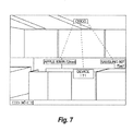
Importantly, FIGS. 5A-5B also demonstrate filtering techniques to show only a specific access point and its corresponding network devices. Such filtering techniques, in further embodiments, includes filtering based upon specific types of devices (e.g., access point devices, rogue devices, routers, printers, etc.), SSIDs, MAC addresses, other network addresses, devices, encryption type, specific transmission type (e.g., 802.11b/g/n/ac, etc.), as is appreciated by those skilled in the art.
The techniques described herein, therefore, provide for identification of network devices via augmented or enhanced reality display devices. In particular, the techniques herein provide identification information as well as additional network status information for respective network devices. Moreover, using these techniques a user can quickly identify network problem for network devices, identify rogue devices, as well as optimize network device location (e.g., based on indicated signal strength).
While there have been shown and described illustrative embodiments that provide for improved visualization of network devices for particular types of communication networks and using a single identification device, it is to be understood that various other adaptations and modifications may be made within the spirit and scope of the embodiments herein. For example, the embodiments have been shown and described herein with relation to wireless networks such as Wifi networks. However, the embodiments in their broader sense are not as limited, and may, in fact, be used with other types of networks and/or protocols. In addition, while certain embodiments are discussed above with respect to one identification device that includes a resident camera and display, multiple network devices may be used to accomplish the same techniques.
The foregoing description has been directed to specific embodiments. It will be apparent, however, that other variations and modifications may be made to the described embodiments, with the attainment of some or all of their advantages. For instance, it is expressly contemplated that the components and/or elements described herein can be implemented as software being stored on a tangible (non-transitory) computer-readable medium (e.g., disks/CDs/RAM/EEPROM/etc.) having program instructions executing on a computer, hardware, firmware, or a combination thereof. Accordingly this description is to be taken only by way of example and not to otherwise limit the scope of the embodiments herein. Therefore, it is the object of the appended claims to cover all such variations and modifications as come within the true spirit and scope of the embodiments herein.
Claims (18)
1. A method, comprising:
receiving, via an identification device, real-time display data, wherein the real-time display data comprises a real image of an environment substantially surrounding the identification device;
determining, via the identification device, a location of a wireless device connected to a communication network;
displaying, via a display of the identification device, an augmented reality image by overlaying an indication of the location of the wireless device relative to the real-time display data over the real image;
determining, via the identification device, whether the wireless device is a rogue device;
displaying, via the display of the identification device, an indication the wireless device is the rogue device, in response to determining that the wireless device is the rogue device;
identifying, via the identification device, a source of wireless noise signals in the communication network;
determining, via the identification device, a location of the source of wireless noise signals within the environment substantially surrounding the identification device; and
modifying, via the display of the identification device, the augmented reality image by overlaying an indication of the location of the source of wireless noise signals relative to the real-time display data over the real image.
2. The method of claim 1 , further comprising:
determining one or more network status conditions of the wireless device; and
wherein displaying the augmented reality image comprises displaying at least a portion of the one or more network status conditions of the wireless device.
3. The method of claim 2 , wherein the wireless device is a Wifi device, wherein the network status conditions comprises at least one of a Media Access Control (MAC) address, an Internet Protocol (IP) address, a name of the Wifi device, a current bandwidth usage of the Wifi device, and a signal strength of the Wifi device.
4. The method of claim 2 , further comprising:
indicating, via the identification device, additional network status conditions are available for the wireless device;
receiving, via the identification device, a request for the additional network status conditions for the wireless device; and
displaying, in response to the request, the additional network status conditions for the wireless device.
5. The method of claim 1 , wherein determining the location of a wireless device comprises determining a distance of the wireless device relative to the identification device based on a signal strength of the wireless device received by the identification device.
6. The method of claim 1 , further comprising:
receiving a plurality of data packets from the wireless device, each data packet being associated with a corresponding signal strength;
wherein determining the location of a wireless device comprises determining a distance of the wireless device relative to the identification device by triangulation of each data packet based on the corresponding signal strength.
7. The method of claim 1 , wherein displaying, via the display of the identification device, the augmented reality image further comprises:
displaying the indication of the location of the wireless device relative to the identification device with a closer relative location corresponding to a larger indication and a further relative location corresponding to a smaller indication.
8. The method of claim 1 , wherein displaying the augmented reality image further comprises:
displaying the real-time display data according to a color scheme.
9. An apparatus, comprising:
one or more network interfaces adapted to communicate in a communication network;
a display;
imaging circuitry;
a processor adapted to execute one or more processes; and
a memory configured to store a process executable by the processor, the process when executed operable to:
receive, via the imaging circuitry, real-time display data, wherein the real-time display data comprises a real image of an environment substantially surrounding the identification device;
determine a location of a wireless device;
display, via the display, an augmented reality image by overlaying an indication of the location of the wireless device relative to the real-time display data over the real image;
determine whether the wireless device is a rogue device;
display an indication the wireless device is the rogue device, in response to determining that the wireless device is the rogue device;
identify a source of wireless noise signals in the communication network;
determine a location of the source of wireless noise signals; and
modify, via the display, the augmented reality image by overlaying an indication of the location of the source of wireless noise signals relative to the real-time display data over the real image.
10. The apparatus of claim 9 , wherein the process when executed is further operable to:
determine one or more network status conditions of the wireless device; and
display the augmented reality image further comprises displaying at least a portion of the one or more network status conditions of the wireless device.
11. The apparatus of claim 10 , wherein the wireless device is a Wifi device, wherein the network status conditions comprises at least one of a Media Access Control (MAC) address, an Internet Protocol (IP) address, a name of the Wifi device, a current bandwidth usage of the Wifi device, and a signal strength of the Wifi device.
12. The apparatus of claim 10 , wherein the process when executed is further operable to:
indicate additional network status conditions are available for the wireless device;
receive a request for the additional network status conditions for the wireless device; and
display the additional network status conditions for the wireless device.
13. The apparatus of claim 9 , wherein determining the location of a wireless device comprises determining a distance of the wireless device relative to the identification device based on a signal strength of the wireless device received by the identification device.
14. The apparatus of claim 9 , wherein the process when executed is further operable to:
receive a plurality of data packets from the wireless device, each data packet being associated with a corresponding signal strength and wherein determining the location of a wireless device comprises determining a distance of the wireless device relative to the identification device by triangulation of each data packet based on the corresponding signal strength.
15. The apparatus of claim 9 , wherein displaying the augmented reality image comprises displaying the indication of the location of the wireless device relative to the identification device with a closer relative location corresponding to a larger indication and a further relative location corresponding to a smaller indication.
16. The apparatus of claim 9 , wherein displaying the—augmented reality image further comprises displaying the real-time display data according to a color scheme.
17. A tangible, non-transitory, computer-readable media having software encoded thereon, the software, when executed by a processor, operable to:
receive real-time display data from an image sensor of an identification device, wherein the real-time display data comprises a real image of an environment substantially surrounding the identification device;
determine a location of a Wifi device;
display the real-time display data and an indication of the location of the Wifi device an augmented reality image by overlaying an indication of the location of the Wifi device relative to the real-time display data over the real image;
determine whether the Wifi device is a rogue device;
display an indication the Wifi device is the rogue device, in response to determining that the Wifi device is the rogue device;
identify a source of Wifi noise signals;
determine a location of the source of Wifi noise signals; and
modify the augmented reality image by overlaying an indication of the location of the source of Wifi noise signals relative to the real-time display data over the real image.
18. The tangible, non-transitory, computer-readable media of claim 17 , wherein the software is further configured to cause the processor to determine one or more network status conditions of the Wifi device and wherein displaying the augmented reality image further comprises displaying at least a portion of the one or more network status conditions of the Wifi device.
Priority Applications (1)
| Application Number | Priority Date | Filing Date | Title |
|---|---|---|---|
| US14/334,482 US9547939B2 (en) | 2013-07-25 | 2014-07-17 | Detecting and visualizing wireless network devices in communication networks |
Applications Claiming Priority (2)
| Application Number | Priority Date | Filing Date | Title |
|---|---|---|---|
| US201361858335P | 2013-07-25 | 2013-07-25 | |
| US14/334,482 US9547939B2 (en) | 2013-07-25 | 2014-07-17 | Detecting and visualizing wireless network devices in communication networks |
Publications (2)
| Publication Number | Publication Date |
|---|---|
| US20150029220A1 US20150029220A1 (en) | 2015-01-29 |
| US9547939B2 true US9547939B2 (en) | 2017-01-17 |
Family
ID=52390117
Family Applications (1)
| Application Number | Title | Priority Date | Filing Date |
|---|---|---|---|
| US14/334,482 Active 2034-07-30 US9547939B2 (en) | 2013-07-25 | 2014-07-17 | Detecting and visualizing wireless network devices in communication networks |
Country Status (1)
| Country | Link |
|---|---|
| US (1) | US9547939B2 (en) |
Cited By (7)
| Publication number | Priority date | Publication date | Assignee | Title |
|---|---|---|---|---|
| US20190372861A1 (en) * | 2018-06-01 | 2019-12-05 | Hewlett Packard Enterprise Development Lp | Network device modifications via augmented reality user interfaces |
| US10685497B1 (en) | 2019-01-15 | 2020-06-16 | International Business Machines Corporation | Visualization of connectivity amelioration within augmented reality and other user interface environments |
| US10827322B1 (en) | 2019-07-05 | 2020-11-03 | Charter Communications Operating, Llc | Augmented reality signal visualization |
| US11126388B2 (en) | 2018-02-23 | 2021-09-21 | Rohde & Schwarz Gmbh & Co. Kg | Measurement instrument identification system as well as method for finding a particular measurement instrument |
| US11768578B2 (en) | 2019-04-17 | 2023-09-26 | Apple Inc. | User interfaces for tracking and finding items |
| US11778421B2 (en) | 2020-09-25 | 2023-10-03 | Apple Inc. | User interfaces for tracking and finding items |
| US11823558B2 (en) | 2019-04-28 | 2023-11-21 | Apple Inc. | Generating tactile output sequences associated with an object |
Families Citing this family (11)
| Publication number | Priority date | Publication date | Assignee | Title |
|---|---|---|---|---|
| RU2695510C2 (en) * | 2014-06-13 | 2019-07-23 | Филипс Лайтинг Холдинг Б.В. | Localization based on network of wireless nodes |
| US20160165449A1 (en) * | 2014-12-03 | 2016-06-09 | Intel Corporation | Notification of unauthorized wireless network devices |
| JP6687835B2 (en) * | 2016-02-10 | 2020-04-28 | 株式会社Jvcケンウッド | Mobile terminal device and program |
| WO2017143239A1 (en) | 2016-02-18 | 2017-08-24 | Edx Wireless, Inc. | Systems and methods for augmented reality representations of networks |
| US10666768B1 (en) * | 2016-09-20 | 2020-05-26 | Alarm.Com Incorporated | Augmented home network visualization |
| US10275943B2 (en) * | 2016-12-13 | 2019-04-30 | Verizon Patent And Licensing Inc. | Providing real-time sensor based information via an augmented reality application |
| CN107505989B (en) * | 2017-09-24 | 2019-10-15 | 肇庆高新区长光智能技术开发有限公司 | Wireless display screen and computer comprising wireless display screen |
| CN107682081B (en) * | 2017-09-24 | 2019-07-09 | 江苏汉德森智能科技有限责任公司 | A kind of wireless display method |
| US10679393B2 (en) | 2018-07-24 | 2020-06-09 | Snap Inc. | Conditional modification of augmented reality object |
| JP7203692B2 (en) | 2019-06-12 | 2023-01-13 | 本田技研工業株式会社 | Information processing device, information processing method, and program |
| BR112022005275A2 (en) * | 2019-09-25 | 2022-06-14 | Noodle Tech Inc | Augmentation of reality by capturing signals using wireless radios |
Citations (11)
| Publication number | Priority date | Publication date | Assignee | Title |
|---|---|---|---|---|
| US7295119B2 (en) * | 2003-01-22 | 2007-11-13 | Wireless Valley Communications, Inc. | System and method for indicating the presence or physical location of persons or devices in a site specific representation of a physical environment |
| US20090019152A1 (en) * | 2007-07-12 | 2009-01-15 | Sextant Navigation, Inc. | Apparatus and Method for Real-Time Monitoring and Controlling of Networked Appliances Using an Intermediate Server |
| US20090235354A1 (en) * | 2003-02-18 | 2009-09-17 | Aruba Networks, Inc. | Method for detecting rogue devices operating in wireless and wired computer network environments |
| US7668570B2 (en) * | 2003-08-12 | 2010-02-23 | Kabushiki Kaisha Toshiba | Information processing apparatus and information processing program |
| US20100087144A1 (en) * | 2008-10-02 | 2010-04-08 | Roni Korenshtein | Short Range Exchange of Information |
| US20110012775A1 (en) * | 2007-11-15 | 2011-01-20 | Loc8Tor Ltd | Locating System |
| US20130107057A1 (en) * | 2010-07-02 | 2013-05-02 | Thomson Licensing | Method and apparatus for object tracking and recognition |
| US20140055490A1 (en) * | 2012-08-22 | 2014-02-27 | Cable Television Laboratories, Inc. | Service coverage identification using augmented reality |
| US20140089810A1 (en) * | 2012-09-27 | 2014-03-27 | Futurewei Technologies, Co. | Real Time Visualization of Network Information |
| US20140335795A1 (en) * | 2013-05-10 | 2014-11-13 | John Russell Wilbur | Software Applications For Displaying And Or Recording Receiver Signal Strengths And Other Parameters |
| US20150332505A1 (en) * | 2012-12-21 | 2015-11-19 | Metaio Gmbh | Method for Representing Virtual Information in a Real Environment |
-
2014
- 2014-07-17 US US14/334,482 patent/US9547939B2/en active Active
Patent Citations (11)
| Publication number | Priority date | Publication date | Assignee | Title |
|---|---|---|---|---|
| US7295119B2 (en) * | 2003-01-22 | 2007-11-13 | Wireless Valley Communications, Inc. | System and method for indicating the presence or physical location of persons or devices in a site specific representation of a physical environment |
| US20090235354A1 (en) * | 2003-02-18 | 2009-09-17 | Aruba Networks, Inc. | Method for detecting rogue devices operating in wireless and wired computer network environments |
| US7668570B2 (en) * | 2003-08-12 | 2010-02-23 | Kabushiki Kaisha Toshiba | Information processing apparatus and information processing program |
| US20090019152A1 (en) * | 2007-07-12 | 2009-01-15 | Sextant Navigation, Inc. | Apparatus and Method for Real-Time Monitoring and Controlling of Networked Appliances Using an Intermediate Server |
| US20110012775A1 (en) * | 2007-11-15 | 2011-01-20 | Loc8Tor Ltd | Locating System |
| US20100087144A1 (en) * | 2008-10-02 | 2010-04-08 | Roni Korenshtein | Short Range Exchange of Information |
| US20130107057A1 (en) * | 2010-07-02 | 2013-05-02 | Thomson Licensing | Method and apparatus for object tracking and recognition |
| US20140055490A1 (en) * | 2012-08-22 | 2014-02-27 | Cable Television Laboratories, Inc. | Service coverage identification using augmented reality |
| US20140089810A1 (en) * | 2012-09-27 | 2014-03-27 | Futurewei Technologies, Co. | Real Time Visualization of Network Information |
| US20150332505A1 (en) * | 2012-12-21 | 2015-11-19 | Metaio Gmbh | Method for Representing Virtual Information in a Real Environment |
| US20140335795A1 (en) * | 2013-05-10 | 2014-11-13 | John Russell Wilbur | Software Applications For Displaying And Or Recording Receiver Signal Strengths And Other Parameters |
Cited By (11)
| Publication number | Priority date | Publication date | Assignee | Title |
|---|---|---|---|---|
| US11126388B2 (en) | 2018-02-23 | 2021-09-21 | Rohde & Schwarz Gmbh & Co. Kg | Measurement instrument identification system as well as method for finding a particular measurement instrument |
| US20190372861A1 (en) * | 2018-06-01 | 2019-12-05 | Hewlett Packard Enterprise Development Lp | Network device modifications via augmented reality user interfaces |
| US10685497B1 (en) | 2019-01-15 | 2020-06-16 | International Business Machines Corporation | Visualization of connectivity amelioration within augmented reality and other user interface environments |
| US10692295B1 (en) | 2019-01-15 | 2020-06-23 | International Business Machines Corporation | Visualization of connectivity amelioration within augmented reality and other user interface environments |
| US11768578B2 (en) | 2019-04-17 | 2023-09-26 | Apple Inc. | User interfaces for tracking and finding items |
| US11960699B2 (en) * | 2019-04-17 | 2024-04-16 | Apple Inc. | User interfaces for tracking and finding items |
| US11966556B2 (en) * | 2019-04-17 | 2024-04-23 | Apple Inc. | User interfaces for tracking and finding items |
| US11823558B2 (en) | 2019-04-28 | 2023-11-21 | Apple Inc. | Generating tactile output sequences associated with an object |
| US10827322B1 (en) | 2019-07-05 | 2020-11-03 | Charter Communications Operating, Llc | Augmented reality signal visualization |
| US11778421B2 (en) | 2020-09-25 | 2023-10-03 | Apple Inc. | User interfaces for tracking and finding items |
| US11968594B2 (en) | 2020-09-25 | 2024-04-23 | Apple Inc. | User interfaces for tracking and finding items |
Also Published As
| Publication number | Publication date |
|---|---|
| US20150029220A1 (en) | 2015-01-29 |
Similar Documents
| Publication | Publication Date | Title |
|---|---|---|
| US9547939B2 (en) | Detecting and visualizing wireless network devices in communication networks | |
| CN107003739B (en) | Docking system | |
| US11445026B2 (en) | Methods, systems, and media for indicating a security status of an internet of things device | |
| US20200320796A1 (en) | Augmented reality video communications | |
| KR100979200B1 (en) | GIS based network information monitoring system | |
| US9690536B2 (en) | Terminal device, and screen-sharing display method and system | |
| KR102182162B1 (en) | Head mounted display and method for controlling the same | |
| US20190312774A1 (en) | System and Method for Facilitating Installation and Configuration of Network Devices | |
| CN104349109A (en) | Information processing method and electronic equipment | |
| KR20220063205A (en) | Augmented reality for setting up an internet connection | |
| US9674664B1 (en) | Mobile device in-motion proximity guidance system | |
| CN103674037A (en) | Information processing method and device | |
| CN102025829A (en) | Methods and devices for displaying an overlay on a device display screen | |
| KR102617715B1 (en) | Electronic device and controlling method of electronic device | |
| JP2017118489A (en) | System and method using machine readable code for testing communication network | |
| US11954787B2 (en) | Image rendering method in panoramic application and terminal device | |
| US20150161923A1 (en) | Electronic device, display device, method, and computer program product | |
| CN107913519B (en) | Rendering method of 2D game and mobile terminal | |
| US10656802B2 (en) | User interface component registry | |
| KR101745594B1 (en) | Apparatus and method for setting up automatically a scene in a virtual desktop service system | |
| JPWO2014156316A1 (en) | Information processing apparatus, information processing method, and information processing system | |
| US11362864B2 (en) | Communication control system, communication control device and communication control method | |
| CN109525379B (en) | Reference signal transmission processing method, network side equipment and user terminal | |
| US20180191998A1 (en) | Video communication method and system | |
| JP2006074532A (en) | Communication line establishment system and method, program and recording medium |
Legal Events
| Date | Code | Title | Description |
|---|---|---|---|
| AS | Assignment |
Owner name: FLUKE CORPORATION, WASHINGTON Free format text: ASSIGNMENT OF ASSIGNORS INTEREST;ASSIGNORS:HITTEL, JOHN P., MR.;OAKLEY, PETER Q., MR.;SIGNING DATES FROM 20140623 TO 20140716;REEL/FRAME:033488/0684 |
|
| STCF | Information on status: patent grant |
Free format text: PATENTED CASE |
|
| MAFP | Maintenance fee payment |
Free format text: PAYMENT OF MAINTENANCE FEE, 4TH YEAR, LARGE ENTITY (ORIGINAL EVENT CODE: M1551); ENTITY STATUS OF PATENT OWNER: LARGE ENTITY Year of fee payment: 4 |