US9545459B2 - Container for surgical instruments and system including same - Google Patents
Container for surgical instruments and system including same Download PDFInfo
- Publication number
- US9545459B2 US9545459B2 US13/436,858 US201213436858A US9545459B2 US 9545459 B2 US9545459 B2 US 9545459B2 US 201213436858 A US201213436858 A US 201213436858A US 9545459 B2 US9545459 B2 US 9545459B2
- Authority
- US
- United States
- Prior art keywords
- shell
- wall
- orientation
- coupled
- define
- Prior art date
- Legal status (The legal status is an assumption and is not a legal conclusion. Google has not performed a legal analysis and makes no representation as to the accuracy of the status listed.)
- Active, expires
Links
Images


Classifications
-
- A—HUMAN NECESSITIES
- A61—MEDICAL OR VETERINARY SCIENCE; HYGIENE
- A61L—METHODS OR APPARATUS FOR STERILISING MATERIALS OR OBJECTS IN GENERAL; DISINFECTION, STERILISATION OR DEODORISATION OF AIR; CHEMICAL ASPECTS OF BANDAGES, DRESSINGS, ABSORBENT PADS OR SURGICAL ARTICLES; MATERIALS FOR BANDAGES, DRESSINGS, ABSORBENT PADS OR SURGICAL ARTICLES
- A61L2/00—Methods or apparatus for disinfecting or sterilising materials or objects other than foodstuffs or contact lenses; Accessories therefor
- A61L2/26—Accessories or devices or components used for biocidal treatment
-
- A—HUMAN NECESSITIES
- A61—MEDICAL OR VETERINARY SCIENCE; HYGIENE
- A61B—DIAGNOSIS; SURGERY; IDENTIFICATION
- A61B50/00—Containers, covers, furniture or holders specially adapted for surgical or diagnostic appliances or instruments, e.g. sterile covers
- A61B50/30—Containers specially adapted for packaging, protecting, dispensing, collecting or disposing of surgical or diagnostic appliances or instruments
-
- A—HUMAN NECESSITIES
- A61—MEDICAL OR VETERINARY SCIENCE; HYGIENE
- A61B—DIAGNOSIS; SURGERY; IDENTIFICATION
- A61B17/00—Surgical instruments, devices or methods, e.g. tourniquets
- A61B17/14—Surgical saws ; Accessories therefor
- A61B17/15—Guides therefor
- A61B17/154—Guides therefor for preparing bone for knee prosthesis
-
- A—HUMAN NECESSITIES
- A61—MEDICAL OR VETERINARY SCIENCE; HYGIENE
- A61B—DIAGNOSIS; SURGERY; IDENTIFICATION
- A61B17/00—Surgical instruments, devices or methods, e.g. tourniquets
- A61B2017/00017—Electrical control of surgical instruments
- A61B2017/00199—Electrical control of surgical instruments with a console, e.g. a control panel with a display
-
- A—HUMAN NECESSITIES
- A61—MEDICAL OR VETERINARY SCIENCE; HYGIENE
- A61B—DIAGNOSIS; SURGERY; IDENTIFICATION
- A61B50/00—Containers, covers, furniture or holders specially adapted for surgical or diagnostic appliances or instruments, e.g. sterile covers
- A61B2050/005—Containers, covers, furniture or holders specially adapted for surgical or diagnostic appliances or instruments, e.g. sterile covers with a lid or cover
- A61B2050/0067—Types of closures or fasteners
- A61B2050/0082—Rib-and-groove connection
-
- A—HUMAN NECESSITIES
- A61—MEDICAL OR VETERINARY SCIENCE; HYGIENE
- A61B—DIAGNOSIS; SURGERY; IDENTIFICATION
- A61B90/00—Instruments, implements or accessories specially adapted for surgery or diagnosis and not covered by any of the groups A61B1/00 - A61B50/00, e.g. for luxation treatment or for protecting wound edges
- A61B90/06—Measuring instruments not otherwise provided for
- A61B2090/064—Measuring instruments not otherwise provided for for measuring force, pressure or mechanical tension
-
- A—HUMAN NECESSITIES
- A61—MEDICAL OR VETERINARY SCIENCE; HYGIENE
- A61B—DIAGNOSIS; SURGERY; IDENTIFICATION
- A61B90/00—Instruments, implements or accessories specially adapted for surgery or diagnosis and not covered by any of the groups A61B1/00 - A61B50/00, e.g. for luxation treatment or for protecting wound edges
- A61B90/08—Accessories or related features not otherwise provided for
- A61B2090/0807—Indication means
-
- A—HUMAN NECESSITIES
- A61—MEDICAL OR VETERINARY SCIENCE; HYGIENE
- A61B—DIAGNOSIS; SURGERY; IDENTIFICATION
- A61B90/00—Instruments, implements or accessories specially adapted for surgery or diagnosis and not covered by any of the groups A61B1/00 - A61B50/00, e.g. for luxation treatment or for protecting wound edges
- A61B90/08—Accessories or related features not otherwise provided for
- A61B2090/0813—Accessories designed for easy sterilising, i.e. re-usable
-
- A—HUMAN NECESSITIES
- A61—MEDICAL OR VETERINARY SCIENCE; HYGIENE
- A61F—FILTERS IMPLANTABLE INTO BLOOD VESSELS; PROSTHESES; DEVICES PROVIDING PATENCY TO, OR PREVENTING COLLAPSING OF, TUBULAR STRUCTURES OF THE BODY, e.g. STENTS; ORTHOPAEDIC, NURSING OR CONTRACEPTIVE DEVICES; FOMENTATION; TREATMENT OR PROTECTION OF EYES OR EARS; BANDAGES, DRESSINGS OR ABSORBENT PADS; FIRST-AID KITS
- A61F2/00—Filters implantable into blood vessels; Prostheses, i.e. artificial substitutes or replacements for parts of the body; Appliances for connecting them with the body; Devices providing patency to, or preventing collapsing of, tubular structures of the body, e.g. stents
- A61F2/02—Prostheses implantable into the body
- A61F2/30—Joints
- A61F2/38—Joints for elbows or knees
- A61F2/389—Tibial components
-
- A—HUMAN NECESSITIES
- A61—MEDICAL OR VETERINARY SCIENCE; HYGIENE
- A61F—FILTERS IMPLANTABLE INTO BLOOD VESSELS; PROSTHESES; DEVICES PROVIDING PATENCY TO, OR PREVENTING COLLAPSING OF, TUBULAR STRUCTURES OF THE BODY, e.g. STENTS; ORTHOPAEDIC, NURSING OR CONTRACEPTIVE DEVICES; FOMENTATION; TREATMENT OR PROTECTION OF EYES OR EARS; BANDAGES, DRESSINGS OR ABSORBENT PADS; FIRST-AID KITS
- A61F2/00—Filters implantable into blood vessels; Prostheses, i.e. artificial substitutes or replacements for parts of the body; Appliances for connecting them with the body; Devices providing patency to, or preventing collapsing of, tubular structures of the body, e.g. stents
- A61F2/02—Prostheses implantable into the body
- A61F2/30—Joints
- A61F2/46—Special tools or methods for implanting or extracting artificial joints, accessories, bone grafts or substitutes, or particular adaptations therefor
- A61F2/4657—Measuring instruments used for implanting artificial joints
- A61F2002/4658—Measuring instruments used for implanting artificial joints for measuring dimensions, e.g. length
- A61F2002/4661—Measuring instruments used for implanting artificial joints for measuring dimensions, e.g. length for measuring thickness
-
- A—HUMAN NECESSITIES
- A61—MEDICAL OR VETERINARY SCIENCE; HYGIENE
- A61F—FILTERS IMPLANTABLE INTO BLOOD VESSELS; PROSTHESES; DEVICES PROVIDING PATENCY TO, OR PREVENTING COLLAPSING OF, TUBULAR STRUCTURES OF THE BODY, e.g. STENTS; ORTHOPAEDIC, NURSING OR CONTRACEPTIVE DEVICES; FOMENTATION; TREATMENT OR PROTECTION OF EYES OR EARS; BANDAGES, DRESSINGS OR ABSORBENT PADS; FIRST-AID KITS
- A61F2/00—Filters implantable into blood vessels; Prostheses, i.e. artificial substitutes or replacements for parts of the body; Appliances for connecting them with the body; Devices providing patency to, or preventing collapsing of, tubular structures of the body, e.g. stents
- A61F2/02—Prostheses implantable into the body
- A61F2/30—Joints
- A61F2/46—Special tools or methods for implanting or extracting artificial joints, accessories, bone grafts or substitutes, or particular adaptations therefor
- A61F2/4657—Measuring instruments used for implanting artificial joints
- A61F2002/4666—Measuring instruments used for implanting artificial joints for measuring force, pressure or mechanical tension
-
- A—HUMAN NECESSITIES
- A61—MEDICAL OR VETERINARY SCIENCE; HYGIENE
- A61L—METHODS OR APPARATUS FOR STERILISING MATERIALS OR OBJECTS IN GENERAL; DISINFECTION, STERILISATION OR DEODORISATION OF AIR; CHEMICAL ASPECTS OF BANDAGES, DRESSINGS, ABSORBENT PADS OR SURGICAL ARTICLES; MATERIALS FOR BANDAGES, DRESSINGS, ABSORBENT PADS OR SURGICAL ARTICLES
- A61L2202/00—Aspects relating to methods or apparatus for disinfecting or sterilising materials or objects
- A61L2202/10—Apparatus features
- A61L2202/18—Aseptic storing means
- A61L2202/182—Rigid packaging means
-
- A—HUMAN NECESSITIES
- A61—MEDICAL OR VETERINARY SCIENCE; HYGIENE
- A61L—METHODS OR APPARATUS FOR STERILISING MATERIALS OR OBJECTS IN GENERAL; DISINFECTION, STERILISATION OR DEODORISATION OF AIR; CHEMICAL ASPECTS OF BANDAGES, DRESSINGS, ABSORBENT PADS OR SURGICAL ARTICLES; MATERIALS FOR BANDAGES, DRESSINGS, ABSORBENT PADS OR SURGICAL ARTICLES
- A61L2202/00—Aspects relating to methods or apparatus for disinfecting or sterilising materials or objects
- A61L2202/20—Targets to be treated
- A61L2202/24—Medical instruments, e.g. endoscopes, catheters, sharps
Definitions
- the present disclosure relates generally to orthopaedic surgical instruments and, more particularly, to containers for surgical instruments used during orthopaedic surgical procedures.
- Joint arthroplasty is a well-known surgical procedure by which a diseased and/or damaged natural joint is replaced by a prosthetic joint.
- a prosthetic joint For example, in a total knee arthroplasty surgical procedure, a patient's natural knee joint is partially or totally replaced by a prosthetic knee joint.
- orthopaedic surgeons may use a variety of orthopaedic surgical instruments such as, for example, sensors, controllers, reamers, drill guides, and/or other surgical instruments.
- orthopaedic surgical instruments are cleaned and sterilized for use in a particular orthopaedic surgical procedure.
- the instruments may be autoclaved.
- the orthopaedic surgical instruments are placed in sterilization packages or containers for cleaning and sterilization.
- Other orthopaedic surgical instruments are not cleaned and sterilized before use in a particular orthopaedic surgical procedure.
- Such non-sterile instruments may be placed in a sealed package or container to prevent contamination of the sterilized surgical instruments or the patient.
- a container for surgical instruments includes a first shell and a second shell configured to be coupled to the first shell to define a chamber therebetween.
- the second shell may be configured to be coupled to the first shell in a plurality of orientations including a first orientation in which the first shell and the second shell cooperate to define a vent that permits fluid to advance into and out of the chamber, and a second orientation in which the first shell and the second shell cooperate to prevent fluid from advancing into and out of the chamber.
- a first passageway may be defined in the first shell, and a second passageway may be defined in the second shell.
- the first passageway When the second shell is coupled to the first shell in the first orientation, the first passageway may be aligned with the second passageway to define the vent.
- the first passageway When the second shell is coupled to the first shell in the second orientation, the first passageway may be spaced apart from the second passageway.
- the first shell may include a rim that defines an outward-facing opening, an inner wall that extends inwardly from the opening to define a compartment in the first shell, and an outer wall that extends from the rim opposite the inner wall.
- the first passageway may be a channel defined in the rim that extends through the inner wall and the outer wall.
- the second shell may include an inner wall that is configured to engage the outer wall of the first shell when the second shell is coupled to the first shell.
- the second passageway may extend through the inner wall of the second shell.
- the first shell may include a flange extending outwardly from the outer wall.
- the second shell may include a flange that is engaged with the flange of the first shell when the second shell is coupled to the first shell.
- the second passageway may be a channel extending through the inner wall and the flange of the second shell.
- the compartment of the first shell may be a first compartment.
- the second shell may include a rim that defines an outward-facing opening, and an inner wall that extends inwardly from the opening to define a second compartment in the second shell.
- the inner wall of the second shell may engage the outer wall of the first shell.
- the first compartment and the second compartment may cooperate to define the chamber.
- the container may also include an indicator configured to indicate a selected orientation of the plurality of orientations of the second shell relative to the first shell.
- the indicator may include a first arrow defined in the first shell, and a second arrow defined in the second shell. The first arrow and the second arrow may point in a first direction when the second shell is coupled to the first shell in the first orientation. In some embodiments, the first arrow may point in the first direction and the second arrow may point in a second direction opposite the first direction when the second shell is coupled to the first shell in the second orientation.
- the first shell and the second shell when the second shell is coupled to the first shell in the first orientation, the first shell and the second shell may cooperate to define a receptacle sized to receive a first orthopaedic surgical instrument of the orthopaedic surgical instruments. Additionally, in some embodiments, when the second shell is coupled to the first shell in the first orientation, the first shell and the second shell may cooperate to define a second receptacle sized to receive a second orthopaedic surgical instrument of the orthopaedic surgical instruments.
- the vent defined by the first shell and the second shell when the second shell is coupled to the first shell in the first orientation may be a plurality of vents that permit fluid to advance into and out of the chamber.
- a system for use in an orthopaedic surgical procedure includes an orthopaedic surgical instrument having a first side and a second side, a first shell defining a first slot sized to receive the first side of the orthopaedic surgical instrument, and a second shell configured to be coupled to the first shell.
- the second shell defines a second slot sized to receive the second side of the orthopaedic surgical instrument.
- the second shell is configured to be coupled to the first shell in a plurality of orientations including a first orientation in which the first slot and the second slot cooperate to define a receptacle sized to receive the orthopaedic surgical instrument.
- the second shell When the second shell is coupled to the first shell in the first orientation, fluid is permitted to advance into and out of the receptacle.
- the orthopaedic surgical instrument When the orthopaedic surgical instrument is received in the first slot of the first shell and the second shell is in a second orientation of the plurality of orientations, the second shell is configured to engage the orthopaedic surgical instrument such that the second shell is prevented from being coupled to the first shell in the second orientation.
- the first shell may include a rim that defines an outward-facing opening and an inner wall that extends inwardly from the opening to a base wall.
- the inner wall and the base wall may define a compartment in the first shell that includes the first slot.
- the first slot of the first shell may include a first end defined by a first inner surface of the first shell located in an imaginary plane positioned between the rim and the base wall, and a curved surface extending upwardly from the first inner surface.
- the first slot may include a second end defined by a second inner surface, a third inner surface, and a fourth inner surface.
- the second inner surface may be located in a second imaginary plane positioned between the rim and the base wall and may extend parallel to the first inner surface.
- the third inner surface may be located in a third imaginary plane positioned between the rim and the second imaginary plane, and the fourth inner surface may extend obliquely between the second inner surface and the third inner surface.
- the second shell may include a rim that defines an outward-facing opening and an inner wall that extends inwardly from the opening to a base wall.
- the inner wall and the base wall may define a compartment in the second shell that includes the second slot.
- the second slot of the second shell may include a first end defined by a first inner surface of the second shell.
- the first inner surface may be located in a fourth imaginary plane positioned between the rim and the base wall of the second shell.
- the second slot may have a second end defined by a second inner surface, a third inner surface, and a fourth inner surface of the second shell.
- the second inner surface of the second shell may be located in a fifth imaginary plane positioned between the rim and the base wall of the second shell.
- the third inner surface may be located in a sixth imaginary plane positioned between the rim of the second shell and the fifth imaginary plane.
- the fourth inner surface of the second shell may extend obliquely between the second inner surface and the third inner surface of the second shell.
- the first end of the first slot of the first shell and the first end of the second slot of the second shell may be aligned to define a first end of the receptacle, and the second end of the first slot and the second end of the second slot may be aligned to define a second end of the receptacle.
- the first end of the first slot may be aligned with the second end of the second slot.
- the system may include a second orthopaedic surgical instrument.
- the first shell and the second shell may cooperate to define a second receptacle sized to receive the second orthopaedic surgical instrument.
- fluid when the second shell is coupled to the first shell in the second orientation, fluid may be prevented from advancing into and out of the second receptacle.
- the system includes a container.
- the container includes a first shell including a rim that defines an outward-facing opening, and an inner wall that extends inwardly from the opening to a base wall.
- the inner wall and the base wall define a first compartment.
- the first shell includes an outer wall that extends from the rim opposite the inner wall.
- the container also includes a second shell configured to be coupled to the first shell in a plurality of orientations.
- the second shell includes a rim that defines an outward-facing opening, an inner wall that extends inwardly from the opening to a base wall.
- the inner wall and the base wall of the second shell define a second compartment.
- the plurality of orientations include a first orientation in which fluid is permitted to advance into and out of the chamber and a second orientation in which fluid is prevented from advancing into and out of the chamber.
- the first shell may include a first passageway that extends through the inner wall and the outer wall of the first shell.
- the first passageway may be aligned with a second passageway of the second shell to permit fluid to advance into and out of the chamber.
- the first passageway may be spaced apart from the second passageway to prevent fluid from advancing into and out of the chamber.
- the inner wall of the second shell may be positioned over the first passageway of the first shell when the second shell is coupled to the first shell in the second orientation.
- the first passageway may include a first channel defined in the rim of the first shell, and the second passageway may include a second channel defined in the second shell.
- the system may include a first orthopaedic surgical instrument, and a second orthopaedic surgical instrument.
- the chamber When the second shell is coupled to the first shell in the first orientation, the chamber may include a first receptacle sized to receive the first orthopaedic surgical instrument.
- the chamber When the second shell is coupled to the first shell in the second orientation, the chamber may include a second receptacle sized to receive the second orthopaedic surgical instrument.
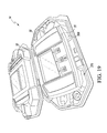
- FIG. 1 is an exploded perspective view of an orthopaedic surgical instrument system
- FIG. 2 is a perspective view of a disassembled surgical instrument container of the system of FIG. 1 ;
- FIG. 3 is a perspective view of a lower shell of the surgical instrument container of FIG. 2 ;
- FIG. 4 is a perspective view of an upper shell of the surgical instrument container of FIG. 2 ;
- FIG. 5 is a cross-sectional side elevation view of the surgical instrument container of FIG. 2 showing the lower shell and the upper shell secured together in one orientation;
- FIG. 6 is a cross-sectional side elevation view similar to FIG. 4 of the surgical instrument container showing the lower shell and the upper shell secured together in another orientation;
- FIG. 7 is a perspective view of a vent formed in the container when the instrument container is assembled as shown in FIG. 5 ;
- FIG. 8 is a perspective view of a passageway of the lower shell when the instrument container is assembled as shown in FIG. 6 ;
- FIG. 9 is a top plan view of an indicator of the instrument container when the instrument container is assembled as shown in FIG. 5 ;
- FIG. 10 is a top plan view of the indicator of the instrument container when the instrument container is assembled as shown in FIG. 6 ;
- FIG. 11 is an exploded perspective view of an orthopaedic surgical instrument of the system of FIG. 1 ;
- FIG. 12 is a perspective view of another orthopaedic surgical instrument of the system of FIG. 1 ;
- FIG. 13 is a perspective view of the disassembled surgical instrument container with the orthopaedic surgical instrument of FIG. 11 positioned in the lower shell;
- FIG. 14 is a perspective view of the assembled surgical instrument container showing the orthopaedic surgical instrument of FIG. 11 positioned therein;
- FIG. 15 is a cross-sectional side elevation view of the surgical instrument container assembled as shown in FIG. 14 ;
- FIG. 16 is another perspective view of the instrument container showing the orthopaedic surgical instrument of FIG. 11 positioned therein;
- FIG. 17 is a cross-sectional side elevation view of the surgical instrument container when assembled as shown in FIG. 16 ;
- FIG. 18 is another perspective view of the surgical instrument container with another orthopaedic surgical instrument positioned in the lower shell;
- FIG. 19 is another perspective view of the surgical instrument container with the orthopaedic surgical instrument of FIG. 12 positioned in the lower shell;
- FIG. 20 is a perspective view of the assembled surgical instrument container showing the orthopaedic surgical instrument of FIG. 12 positioned therein;
- FIG. 21 is a cross-sectional side elevation view of the surgical instrument container assembled as shown in FIG. 20 .
- anatomical references such as anterior, posterior, medial, lateral, superior, inferior, etcetera
- terms representing anatomical references may be used throughout the specification in reference to the orthopaedic implants and surgical instruments described herein as well as in reference to the patient's natural anatomy.
- Such terms have well-understood meanings in both the study of anatomy and the field of orthopaedics. Use of such anatomical reference terms in the written description and claims is intended to be consistent with their well-understood meanings unless noted otherwise.
- a system 10 for use in an orthopaedic surgical procedure includes a plurality of orthopaedic surgical instruments 12 and a surgical instrument container 14 capable of carrying any of the instruments 12 .
- the instruments 12 include a sensor module 16 , an adaptor 18 , and a hand-held display module 20 , which may be used to determine and display joint forces of a patient's joint during the orthopaedic surgical procedure.
- the plurality of surgical instruments may include additional or other instruments, such as, for example, reamers, saw blade, prosthetic trails, and so forth.
- the container 14 and the system 10 are described below in regard to instruments for use in one arthroplasty surgical procedure, certain concepts associated with the container 14 and the system 10 may be utilized in replacement procedures of numerous other joints throughout the body.
- the container 14 of the system 10 includes a shell 30 and a shell 32 configured to be coupled to the shell 30 .
- the shells 30 , 32 are respectively described below as “a lower shell 30 ” and “an upper shell 32 ,” and some structures of the shells 30 , 32 are described in reference to directions such as, for example, vertical, horizontal, upward, downward, and so forth.
- the shells 30 , 32 may be flipped or switched such that the shell 30 is the upper shell and the shell 32 is the lower shell.
- the shells 30 , 32 may be rotated such that one shell is “a right shell” or “front shell” and the other is “a left shell” or “rear shell.”
- each of the shells 30 , 32 is formed from a rigid, transparent plastic that has been molded into the required shape.
- the shells may be formed from a plastic that is semi-transparent or opaque. It should also be appreciated that in other embodiments the shells may be formed from another polymeric material or a metallic material such as, for example, aluminum.
- the lower shell 30 of the container 14 defines a compartment 34 having an opening 36 that is defined by a rim 38 .
- the lower shell 30 includes an inner wall 40 that extends inwardly from the opening 36 to a base wall 42 .
- the walls 40 , 42 cooperate to define the compartment 34 .
- the lower shell 30 also includes an outer wall 44 that extends away from the rim 38 to a lower end 46 , and a flange 48 that extends outwardly from the lower end 46 of the outer wall 44 .
- a number of passageways 50 are defined in the lower shell 30 , and each passageway 50 is sized to permit fluid, such as, for example, an instrument sterilization gas, to advance into and out of the compartment 34 .
- the passageways 50 of the lower shell 30 include a channel 52 defined in a side 54 of lower shell 30 .
- the channel 52 includes a notch 56 defined in the rim 38 and the inner wall 40 .
- the channel 52 also includes an opening 58 defined in the outer wall 44 .
- the channel 52 is defined between a pair of opposing surfaces 60 that extend downwardly from the notch 56 and inwardly from the opening 58 to a pair of walls 62 , 64 .
- the channel 52 is further defined by another wall 66 that extends inwardly from the opening 58 to a lower end 68 of the wall 64 .
- each opposing surface 60 includes a section 76 that extends downwardly from the notch 56 to the wall 62 , which is positioned between the rim 38 and the lower end 46 of the outer wall 44 .
- the sections 76 of the surfaces 60 and the wall 62 define the upper segment 72 .
- Each opposing surface 60 also includes a section 78 that extends inwardly from the opening 58 to the wall 64 , which extends downwardly from an edge 80 of the wall 62 .
- the sections 78 of the surfaces 60 , the wall 64 , and the wall 66 define the lower segment 74 of the channel 52 .
- the channel may have a substantially planar bottom wall.
- the bottom wall of the channel 52 may be angled or sloped.
- the channel 52 of the lower shell 30 defines a longitudinal axis 82 and extends through the outer wall 44 and the inner wall 40 to the compartment 34 .
- the passageways 50 of the lower shell 30 includes another channel 90 that is defined in the side 92 of the lower shell 30 opposite the side 54 .
- the channel 90 also defines a longitudinal axis 94 and extends through the outer wall 44 and the inner wall 40 to the compartment 34 .
- the longitudinal axis 94 is coaxial with the longitudinal axis 82 such that the channels 52 , 90 are aligned. It should be appreciated that in other embodiments the axes 82 , 94 of the channels 52 , 90 may be offset or otherwise not aligned.
- the configuration of the channel 90 is similar to the configuration of the channel 52 described above. As shown in FIG. 3 , the channel 90 includes a notch 96 defined in the rim 38 and the inner wall 40 . The channel 90 also includes an opening 98 defined in the outer wall 44 . The channel 90 is defined between a pair of opposing surfaces 100 that extend downwardly from the notch 96 and inwardly from the opening 98 to a pair of walls 102 , 104 . The channel 90 is further defined by another wall 106 that extends inwardly from the opening 98 to a lower end (not shown) of the wall 104 . The walls 102 , 104 , 106 cooperate to define a stepped bottom wall of the channel 90 such that the channel 90 is divided into an upper segment 112 and a lower segment 114 .
- the passageways 50 of the lower shell 30 also include a pair of channels 120 , 122 defined in opposite sides 126 , 128 , respectively, of the lower shell 30 .
- the channels 120 , 122 define longitudinal axes 130 , 132 and extend through the outer wall 44 and the inner wall 40 to the compartment 34 .
- the longitudinal axis 130 is coaxial with the longitudinal axis 132 such that the channels 120 , 122 are aligned.
- the axes 130 , 132 of the channels 120 , 122 may be offset or otherwise not aligned.
- the axes 130 , 132 of the channels 120 , 122 extend orthogonal to the axes 82 , 94 of the channels 52 , 90 .
- the channel 120 includes a notch 136 defined in the rim 38 and the inner wall 40 on the side 126 .
- the channel 120 also includes an opening 138 defined in the outer wall 44 .
- the channel 120 is defined between a pair of opposing surfaces 140 that extend downwardly from the notch 136 and inwardly from the opening 138 to a pair of walls 142 , 144 .
- the channel 120 is further defined by another wall 146 that extends inwardly from the opening 138 to a lower end 148 of the wall 144 .
- each opposing surface 140 includes a section 156 that extends downwardly from the notch 136 to the wall 142 , which is positioned between the rim 38 and the lower end 46 of the outer wall 44 .
- the sections 156 of the surfaces 140 and the wall 142 define the upper segment 152 .
- Each opposing surface 140 also includes a section 158 that extends inwardly from the opening 138 to the wall 144 , which extends downwardly from an edge 160 of the wall 142 .
- the sections 158 of the surfaces 140 , the wall 144 , and the wall 146 define the lower segment 154 of the channel 120 .
- the channel may have a substantially planar bottom wall.
- the bottom wall of the channel 120 may be angled or sloped.
- the configuration of the channel 122 is similar to the configuration of the channel 120 described above. As shown in FIG. 3 , the channel 122 includes a notch 186 defined in the rim 38 and the inner wall 40 on the side 128 of the lower shell 30 . The channel 122 also includes an opening 188 defined in the outer wall 44 . The channel 122 is defined between a pair of opposing surfaces 190 that extend downwardly from the notch 186 and inwardly from the opening 188 to a pair of walls 192 , 194 . The channel 122 is further defined by another wall 196 that extends inwardly from the opening 188 to a lower end (not shown) of the wall 194 . The walls 192 , 194 , 196 cooperate to define a stepped bottom wall of the channel 122 such that the channel 122 is divided into an upper segment 202 and a lower segment 204 .
- the passageways 50 defined in the lower shell 30 are the channels 52 , 90 , 120 , 122 defined in the rim 38 . It should be appreciated that in other embodiments the passageways 50 may be bores or through-holes that extend through the inner wall 40 and the outer wall 44 into the compartment 34 . Additionally, in other embodiments additional or fewer passageways may be defined in the lower shell 30 . For example, the shell may have only a single passageway defined therein.
- the compartment 34 of the lower shell 30 includes a number of positioning slots 206 that are sized and shaped to receive portions of the orthopaedic surgical instruments 12 .
- the instruments 12 include a sensor module 16
- the slots 206 include a receiving slot 208 sized and shaped to receive the sensor module 16 .
- the receiving slot 208 has an end 210 located on the side 54 of the lower shell 30 and another end 212 located on the opposite side 92 of the lower shell 30 .
- the channels 52 , 90 open into the ends 210 , 212 , respectively, of the slot 208 .
- the end 210 of the receiving slot 208 is defined by a plurality of inner surfaces 214 of the inner wall 40 , and the inner surface 214 are keyed to match the structure of the end 534 of the sensor module 16 , as described in greater detail below.
- the inner surfaces 214 include a substantially planar surface 216 located in an imaginary plane 218 positioned between the rim 38 and the base wall 42 of the lower shell 30 .
- the inner surfaces 214 also include another substantially planar surface 220 located in an imaginary plane 222 positioned between the plane 218 and the rim 38 .
- An oblique surface 224 connects the surfaces 216 , 220 .
- a groove 226 extends through the surfaces 216 , 220 , 224 to the base wall 42 .
- the inner surfaces 214 also include a pair of surfaces 228 extending upwardly from the surfaces 216 , 220 , 224 .
- the opposite end 212 of the receiving slot 208 is defined by a plurality of inner surfaces 230 of the inner wall 40 that are keyed to match the structure of the tibial paddle 504 of the sensor module 16 , as described in greater detail below.
- the inner surfaces 230 include a substantially planar surface 232 located in an imaginary plane 234 positioned between the rim 38 and the base wall 42 of the lower shell 30 .
- the inner surfaces 230 also include a curved surface 236 that extends vertically from the surface 232 .
- the surgical instruments 12 may include another sensor module 600
- the positioning slots 206 of the lower shell 30 include another receiving slot 240 sized and shaped to receive the sensor module 600 .
- the receiving slot 240 includes the same end 210 as the receiving slot 208 , which is located on the side 54 of the lower shell 30 .
- the receiving slot 240 has another end 242 located on the opposite side 92 of the lower shell 30 .
- the end 242 of the receiving slot 240 is defined by a plurality of inner surfaces 244 of the inner wall 40 that are keyed to match the structure of the larger tibial paddle 602 of the sensor module 600 (see FIG. 18 ), as described in greater detail below. As shown in FIG.
- the inner surfaces 244 include a substantially planar surface 246 located in the imaginary plane 234 .
- the inner surfaces 244 also include a curved surface 248 that extends vertically from the surface 246 .
- a groove 238 extends through the planar surface 246 to the base wall 42 .
- the surgical instruments 12 also include an adaptor 18 for the sensor module 16
- the positioning slots 206 of the lower shell 30 also include a pocket 250 sized to receive the upper retainer clips 556 of the adaptor 18 .
- the pocket 250 is positioned adjacent to the end 210 of the receiving slots 208 , 240 .
- the pocket 250 includes an opening 252 defined in a surface 254 of the inner wall 40 , and a cylindrical inner surface 256 extends downwardly from the opening 252 to a planar surface 258 .
- Another opening 260 is defined in the planar surface 258 , and another inner surface 262 extends downwardly from the opening 260 .
- the surfaces 256 , 258 , 262 cooperate to define a cavity 264 of the pocket 250 .
- the pocket 250 also includes a channel 266 that extends downwardly from the surface 254 of the inner wall 40 .
- the channel 266 is sized to receive an anti-rotation key 560 of the adaptor 18 .
- the surgical instruments 12 also include the display module 20 for the sensor module 16 .
- the positioning slots 206 of the lower shell 30 also include a receiving slot 270 sized and shaped to receive the lower side 598 of the hand-held display module 20 .
- the receiving slot 270 is defined by a pair of ribs 272 , 274 extending upwardly from the base wall 42 .
- the base wall 42 has a substantially planar surface 276 that extends between the ribs 272 , 274 .
- the ribs 272 , 274 and the surface 276 are keyed to match the structure of the lower side 598 of the display module 20 , and, in the illustrative embodiment, the rib 274 includes a slot 280 sized to receive a rib 588 formed on the lower side 598 of the display module 20 , as described in greater detail below.
- the instrument container 14 of the system 10 also includes an upper shell 32 configured to be coupled to the lower shell 30 .
- the upper shell 32 of the container 14 defines a compartment 300 having an opening 302 that is defined by a rim 304 .
- the upper shell 32 includes an inner wall 306 that extends inwardly from the opening 302 to a base wall 308 .
- the walls 306 , 308 cooperate to define the compartment 300 .
- the upper shell 32 also includes a flange 310 that extends outwardly from the rim 304 .
- a number of passageways 312 are defined in the upper shell 32 , and each passageway 312 is sized to permit fluid, such as, for example, an instrument sterilization gas, to advance into and out of the compartment 300 .
- the passageways 312 of the upper shell 32 include channels 314 , 316 , 318 , 320 , which correspond to the channels 52 , 90 , 120 , 122 of the lower shell 30 .
- the channel 314 is defined in a side 324 of the upper shell 32 .
- the channel 314 includes a notch 326 defined in the rim 304 .
- a pair of opposing sloped surfaces 328 extends downwardly from the notch 326 to a substantially planar surface 330 .
- the surfaces 328 , 330 cooperate to define the channel 314 .
- the channel 314 of the upper shell 32 defines a longitudinal axis 332 and extends through the inner wall 306 and the flange 310 to the compartment 300 .
- the channel 316 of the passageways 312 is defined in the side 334 of the upper shell 32 opposite the side 324 .
- the channel 316 also defines a longitudinal axis 336 and extends through the inner wall 306 and the flange 310 to the compartment 300 .
- the longitudinal axis 332 is coaxial with the longitudinal axis 336 such that the channels 314 , 316 are aligned. It should be appreciated that in other embodiments the axes 332 , 336 of the channels 314 , 316 may be offset or otherwise not aligned.
- the configuration of the channel 316 is similar to the configuration of the channel 314 described above.
- the channel 316 includes a notch 340 defined in the rim 304 .
- a pair of opposing sloped surfaces 342 extends downwardly from the notch 340 to a substantially planar surface 344 .
- the surfaces 342 , 344 cooperate to define the channel 316 .
- the passageways 312 of the upper shell 32 also include a pair of channels 318 , 320 defined in opposite sides 350 , 352 , respectively, of the upper shell 32 .
- the channels 318 , 320 define longitudinal axes 354 , 356 , respectively, and extend through the inner wall 306 and the flange 310 to the compartment 300 .
- the longitudinal axis 354 is coaxial with the longitudinal axis 356 such that the channels 318 , 320 are aligned. It should be appreciated that in other embodiments the axes 354 , 356 of the channels 318 , 320 may be offset or otherwise not aligned.
- the axes 354 , 356 of the channels 318 , 320 extend orthogonal to the axes 332 , 336 of the channels 314 , 316 .
- Each of the channels 318 , 320 includes a notch 360 defined in the rim 304 .
- a pair of opposing sloped surfaces 362 extends downwardly from the notch 360 to a substantially planar surface 364 .
- the surfaces 362 , 364 cooperate to define the channel 318 and the channel 320 .
- the passageways 312 defined in the upper shell 32 are the channels 314 , 316 , 318 , 320 defined in the rim 304 . It should be appreciated that in other embodiments the passageways 312 may be bores or through-holes that extend through the upper shell 32 . For example, in other embodiments, the flange 310 may be omitted and the passageways 312 may extend through the inner wall 306 and the outer wall 366 of the upper shell 32 to the compartment 34 . Additionally, in other embodiments additional or fewer passageways may be defined in the upper shell 32 . For example, the shell may have only a single passageway defined therein.
- the compartment 300 of the upper shell 32 includes a number of positioning slots 370 that are sized and shaped to receive portions of the orthopaedic surgical instruments 12 .
- the instruments 12 include a sensor module 16
- the slots 370 include a receiving slot 372 sized and shaped to receive the sensor module 16 .
- the receiving slot 372 has an end 374 located on the side 324 of the upper shell 32 and another end 376 located on the opposite side 334 of the upper shell 32 .
- the end 374 of the receiving slot 372 is defined by a plurality of inner surfaces 378 of the inner wall 306 that are keyed to match the structure of the end 534 of the sensor module 16 , as described in greater detail below.
- the inner surfaces 378 include a substantially planar surface 380 located in an imaginary plane 382 positioned between the rim 304 and the base wall 308 of the upper shell 32 .
- the inner surfaces 378 also include another substantially planar surface 384 located in an imaginary plane 386 positioned between the plane 382 and the rim 304 .
- An oblique surface 388 connects the surfaces 380 , 384 .
- a groove 390 extends through the surfaces 380 , 384 , 388 to the base wall 42 .
- the inner surfaces 378 defining the slot 372 also include a pair of surfaces 392 extending upwardly from the surfaces 380 , 384 , 388 .
- the opposite end 376 of the receiving slot 372 includes a substantially planar surface 394 located in an imaginary plane 396 positioned between the rim 304 and the base wall 308 of the upper shell 32 .
- the surface 394 is configured to engage the tibial paddle 504 of the sensor module 16 .
- a groove 398 extends through the planar surface 394 to the base wall 308 .
- the surgical instruments 12 also include an adaptor 18 for the sensor module 16 .
- the positioning slots 370 of the upper shell 32 also include a pocket 400 sized to receive the lower retainer clips 558 of the adaptor 18 .
- the pocket 400 is positioned adjacent to the end 374 of the receiving slot 372 .
- the pocket 400 includes an opening 402 defined in a surface 404 of the inner wall 306 , and a cylindrical inner surface 406 extends downwardly from the opening 402 to a planar surface 408 .
- Another opening 410 is defined in the planar surface 408 , and another inner surface 412 extends downwardly from the opening 410 .
- the surfaces 406 , 408 , 412 cooperate to define a cavity 414 of the pocket 400 .
- the surgical instruments 12 also include the display module 20 for the sensor module 16 .
- the positioning slots 370 of the upper shell 32 also include a receiving slot 420 sized and shaped to receive the upper side 576 of the hand-held display module 20 .
- the receiving slot 420 is defined by a pair of ribs 422 , 424 positioned on each side of a pair of protrusions 426 , 428 .
- the base wall 308 of the upper shell 32 has a substantially planar surface 430 that extends between the ribs 422 , 424 and the protrusions 426 , 428 .
- the ribs 422 , 424 , the protrusions 426 , 428 , and the surface 430 are keyed to match the structure of the upper side 576 of the display module 20 , as described in greater detail below.
- the upper shell 32 is configured to be secured to the lower shell 30 in a number of different orientations to form the container 14 .
- the rim 38 of the lower shell 30 extends through the opening 302 of the upper shell 32 , and the outer wall 44 of the lower shell 30 engages the inner wall 306 of the upper shell 32 .
- the compartments 34 , 300 of the shells 30 , 32 cooperate to define a chamber 450 within the container 14 .
- the orientations include an open orientation in which fluid is permitted to advance into and out of the chamber 450 .
- the orientations also include a closed orientation in which fluid is prevented advancing into and out of the chamber 450 .
- the upper shell 32 may be secured to the lower shell 30 in the open orientation such that the passageways 50 of the lower shell 30 are aligned with the passageways 312 of the upper shell 32 .
- the passageways 50 , 312 define a plurality of vents 452 that permit fluid to advance into and out of the chamber 450 .
- the channel 52 of the lower shell 30 is aligned with the channel 314 of the upper shell 32 to define a vent 454 extending through the sides 54 , 324 of the shells 30 , 32 to the chamber 450 . Fluid is permitted to advance through the vent 454 in the directions indicated by arrow 456 such that the fluid may advance into and out of the chamber 450 .
- the channel 90 of the lower shell 30 is aligned with the channel 316 of the upper shell 32 to define a vent 458 extending through the side 92 , 334 of the shells 30 , 32 . Fluid is permitted to advance through the vent 458 in the directions indicated by arrow 460 .
- the channels 120 , 320 of the shells 30 , 32 , respectively, and the channels 122 , 318 of the shells 30 , 32 , respectively, are similarly aligned to define additional vents 464 , 462 (see FIG. 14 ) through the container 14 .
- the receiving slots 208 , 372 of the shells 30 , 32 define a receptacle 470 sized to receive the sensor module 16 .
- the end 210 of the receiving slot 208 and the end 374 of the receiving slot 372 are aligned such that the end 534 of the sensor module 16 may be positioned therein.
- the pockets 250 , 400 of the shells 30 , 32 are aligned to define a receptacle 472 sized to receive the adaptor 18 .
- the upper shell 32 may be secured to the lower shell 30 in the closed orientation such that the inner wall 306 of the upper shell 32 is positioned over the passageways 50 of the lower shell 30 such that no vents are defined in the container 14 and fluid is not permitted to advance into and out of the chamber 450 .
- the passageways 312 of the upper shell 32 face the outer wall 44 of the lower shell 30 , and the passageways 50 , 312 are spaced apart from each other.
- the receiving slots 270 , 420 of the shells 30 , 32 respectively, define a receptacle 474 sized to receive the display module 20 .
- the container 14 includes an orientation indicator 480 that provides an indication to the user of the orientation of the upper shell 32 relative to the lower shell 30 .
- the indicator 480 includes a pair of arrows 482 that are defined in the rim 38 on each side 126 , 128 of the lower shell 30 .
- the indicator 480 also includes a pair of arrows 484 that is defined in a surface 486 of the inner wall 306 of the upper shell 32 .
- the arrows 482 , 484 may be etched, imprinted, or other applied to the shells 30 , 32 . It should also be appreciated that in other embodiments the indicator 480 may take the form of other graphics, text, or other media.
- the arrows 482 , 484 point in the same direction when the upper shell 32 is coupled to the lower shell 30 in the open orientation. As shown in FIG. 9 , one of the arrows 484 of the upper shell 32 is positioned over the one of the arrows 482 of the lower shell 30 to indicate the vents 452 are formed in the container 14 . As a result, the user is informed that fluid is permitted to advance into and out of the chamber 450 .
- the arrows 482 , 484 point in opposing directions. As shown in FIG. 10 , the arrows 484 of the upper shell 32 point toward the arrows 482 of the lower shell 30 while the arrows 482 point toward the arrows 484 . As a result, the user is informed that fluid is prevented from advancing into and out of the chamber 450 .
- the system 10 also includes a sensor module 16 , an adaptor 18 , and a display module 20 .
- the sensor module 16 of the system 10 is configured to be inserted into a patient's joint and provide a visual indication of the joint forces to an orthopaedic surgeon.
- the sensor module 16 may also be configured to transmit joint force data to the hand-held display module 20 .
- the display module 20 is configured to display the joint force data, or data derived therefrom, to an orthopaedic surgeon.
- the sensor module 16 includes a sensor housing 500 and a handle 502 coupled to the sensor housing 500 .
- the sensor housing 500 is sized and shaped to be positioned in a joint of the patient.
- the sensor housing 500 is a tibial paddle 504 , which is shaped to be positioned in a knee joint of the patient. It should be appreciated that in other embodiments the sensor housing 500 may be configured to be used with other joints of the patient.
- the tibial paddle 504 includes an upper surface 506 , a lower surface 508 , and a curved side wall 510 that extends between the surfaces 506 , 508 .
- the side wall 510 includes a curved anterior side 512 , a curved lateral side 514 , a curved medial side 516 , and a curved posterior side 518 .
- Each side is shaped to approximate the shape a tibial bearing of an orthopaedic knee prosthesis.
- the “upper surface” and the “lower surface” may be reversed depending on the operative side of the patient.
- the “medial side” and the “lateral side” may be reversed depending on whether the surgeon uses a medial approach or lateral approach during surgery.
- the posterior side 518 includes a posterior notch 520 to allow the tibial paddle 504 to be positioned around the soft tissue of the patient's joint such as the posterior cruciate ligament.
- the overall size of the tibial paddle 504 may be selected based on the particular anatomical structure of the patient. For example, in some embodiments, the tibial paddle 504 may be provided in various sizes to accommodate patients of varying sizes.
- the tibial paddle 504 also includes an opening 522 defined in the upper surface 506 .
- An inner wall 524 extends downwardly from the opening 522 to define a vertical aperture 526 in the paddle 504 .
- the aperture 526 is sized to receive the lower retainer clips 558 of the adaptor 18 .
- the handle 502 includes a body 530 having an end 532 coupled to the tibial paddle 504 .
- the opposite end 534 of the body 530 includes a pair of displays 536 , which are positioned on opposite sides 538 , 540 of the body 530 .
- Each display 536 includes an angled control surface 542 including a number of controls 544 .
- the controls 544 may include, for example, buttons and indicator lights for the sensor module 16 .
- the displays 536 may be embodied as other types of displays such as liquid crystal displays, segmented displays, and/or the like.
- the surgical instruments 12 include an adaptor 18 that is configured to be secured to the tibial paddle 504 .
- the adaptor 18 includes a hub 550 having a bottom side 552 , which contacts or otherwise confronts the tibial paddle 504 when the adaptor 18 is coupled thereto, and a top side 554 opposite the bottom side 552 .
- the hub 550 has a circular shape, or near-circular shape.
- a set of upper retainer clips 556 extend upwardly from the top side 554
- a set of lower retainer clips 558 extend downwardly from the bottom side 552
- an anti-rotation key 560 that extends outwardly from the hub 550 .
- the upper retainer clips 556 are larger than the lower retainer clips 558 such that the upper retainer clips 556 cannot be inserted into the vertical aperture 526 of the tibial paddle 504 .
- the hand-held display module 20 includes a housing 570 .
- the display module 20 also includes a display 572 positioned in a slot 574 defined in an upper side 576 of the housing 570 .
- a plurality of user input buttons 578 , 580 , 582 are positioned in another slot 584 defined in the upper side 576 of the housing 570 below the display 572 .
- the display module 20 also includes a power button 586 positioned in the slot 584 .
- the slots 574 , 584 are positioned between a pair of grooves 590 , 592 defined in the upper side 576 of the housing 570 .
- the housing 570 of the display module 20 also includes a pair of grooves 594 , 596 defined in the lower side 598 thereof.
- a rib 588 is formed on the lower side 598 and extends transverse to the groove 596 .
- the container 14 is capable of carrying any of the surgical instruments 12 depending on the orientation of the upper shell 32 relative to the lower shell 30 .
- the upper shell 32 is positioned in the open orientation relative to the lower shell 30
- the sensor module 16 is received in the lower shell 30 .
- the end 534 of the sensor handle 502 is positioned in the end 210 of the receiving slot 208 while the tibial paddle 504 is positioned in the end 212 of the receiving slot 208 .
- the end 210 of the receiving slot 208 is keyed to match the structure of the end 534 of the sensor handle 502 . For example, as shown in FIG.
- the angled control surface 542 of the display 536 on the sensor handle 502 is engaged with the oblique surface 224 that defines the receiving slot 208 .
- the planar surface 232 of the lower shell 30 engages the lower surface 508 of the tibial paddle 504
- the curved surface 236 engages the curved side wall 510 of the paddle 504 .
- the adaptor 18 is received in the pocket 200 .
- the top side 554 of the hub 550 is engages the surface 258 and the upper retaining clips 556 are received in the cavity 264 .
- the anti-rotation key 560 of the adaptor 18 is positioned in the channel 266 defined in the shell 30 .
- the upper shell 32 When the sensor module 16 is properly positioned in the lower shell 30 , the upper shell 32 may be lowered onto the lower shell 30 in the open orientation. As described above, the rim 38 of the lower shell 30 extends through the opening 302 of the upper shell 32 , and the outer wall 44 of the lower shell 30 engages the inner wall 306 of the upper shell 32 .
- the compartments 34 , 300 of the shells 30 , 32 cooperate to define a chamber 450 within the container 14 . As shown in FIG. 14 , a plurality of vents 452 are defined in the container 14 in the open orientation, which permit fluid to advance into and out of the chamber 450 .
- the indicator arrows 484 of the upper shell 32 are positioned over the arrows 482 of the lower shell 30 to indicate the vents 452 are formed in the container 14 . As a result, the user is informed that fluid is permitted to advance into and out of the chamber 450 .
- the receiving slots 208 , 372 of the shells 30 , 32 define a receptacle 470 that receives the sensor module 16 .
- the end 210 of the receiving slot 208 and the end 374 of the receiving slot 372 are aligned such that the end 534 of the sensor module 16 may be positioned therein.
- the grooves 226 , 390 defined in the surfaces 214 , 378 of the receiving slots 208 , 372 are aligned with controls 544 of the sensor module 16 to prevent accidental activation of the sensor module 16 when it is positioned in the container 14 .
- the other ends 212 , 376 of the slots 208 , 372 are aligned to receive the tibial paddle 504 of the sensor module 16 .
- the pockets 250 , 400 of the shells 30 , 32 are aligned to define a receptacle 472 that receives the adaptor 18 . In that way, the sensor module 16 and the adaptor 18 may be carried together in the container 14 .
- the interaction between the sensor module 16 prevents the upper shell 32 from being attached to the lower shell 30 in the closed orientation when the sensor module 16 is positioned in the lower shell 30 .
- the end 534 of the sensor handle 502 is configured to engage the planar surface 394 of the upper shell 32 such that the upper shell 32 cannot be secured to the lower shell 30 . In that way, the upper shell 32 can be attached to the lower shell 30 in only the open orientation when the sensor module 16 is received in the lower shell 30 .
- the upper shell 32 is oriented in the open orientation relative to the lower shell 30 , and another, larger sensor module 600 is received in the lower shell 30 .
- the sensor module 600 like the sensor module 16 , includes a sensor handle 502 .
- the end 534 of the sensor handle 502 is positioned in the end 210 of the receiving slot 240 .
- the end 210 of the receiving slot 240 is keyed to match the structure of the end 534 of the sensor handle 502 .
- the sensor module 600 also includes a tibial paddle 602 , which is secured to the handle 502 .
- the tibial paddle 602 includes an upper surface 604 , a lower surface 606 , and a curved side wall 608 .
- the tibial paddle 602 is larger than the tibial paddle 504 of the sensor module 16 .
- the tibial paddle 602 is positioned in the end 242 of the receiving slot 240 .
- the planar surface 244 of the lower shell 30 engages the lower surface 606 of the tibial paddle 602
- the curved surface 248 engages the curved side wall 608 of the paddle 602 .
- the upper shell 32 is positioned in the closed orientation relative to the lower shell 30 , and the display module 20 is received in the lower shell 30 .
- the lower side 598 of the display module 20 is positioned in the receiving slot 270 .
- the receiving slot 270 is keyed to match the structure of the lower side 598 of the display module 20 .
- the ribs 272 , 274 extending from the base wall 42 are received in the grooves 594 , 596 , respectively, defined in the lower side 598 of the display module 20 .
- the rib 588 of the display module 20 is received in the slot 280 defined in the rib 274 of the lower shell 30 .
- the upper shell 32 may be lowered onto the lower shell 30 in the closed orientation when the display module 20 is received therein.
- the rim 38 of the lower shell 30 extends through the opening 302 of the upper shell 32 , and the outer wall 44 of the lower shell 30 engages the inner wall 306 of the upper shell 32 .
- the compartments 34 , 300 of the shells 30 , 32 cooperate to define a chamber 450 within the container 14 .
- no vents are defined in the container 14 such that fluid is prevented from advancing into and out of the chamber 450 in the closed orientation.
- the indicator arrows 484 of the upper shell 32 point toward the indicator arrows 482 of the lower shell 30 while the arrows 482 point toward the arrows 484 .
- the user is informed that fluid is prevented from advancing into and out of the chamber 450 .
- the receiving slots 270 , 420 of the shells 30 , 32 define a receptacle 474 that receives the display module 20 .
- the slot 420 of the upper shell 32 is keyed to match the structure of the upper side 576 of the display module 20 .
- the ribs 422 , 424 extending from the base wall 308 are received in the grooves 590 , 592 , respectively, defined in the upper side 576 of the display module 20 .
- the slots 572 , 584 of the display module 20 receive the protrusions 426 , 428 of the upper shell 32
- the rib 588 of the display module 20 is received in the slot 280 defined in the rib 274 of the lower shell 30 .
- a surgeon or other user is prevented attaching the upper shell 32 in the open orientation when the display module 20 is received in the lower shell 30 due to the matching structure of the slots 572 , 584 and the rib 274 of the display module 20 , on one hand, and the protrusions 426 , 428 and the slot 280 of the upper shell 32 , on the other.
- the upper shell 32 may be attached to the lower shell 30 in only the closed orientation.
- a surgeon may access the buttons 578 , 580 , 582 of the display module 20 while the display module 20 is positioned in the container 14 . As shown in FIG. 20 , the surgeon may press on the outer surface 610 of the shell 32 to operate the buttons 578 , 580 , 582 and control the operation of the sensor module 16 and/or display module 20 .
Abstract
Description
Claims (21)
Priority Applications (6)
| Application Number | Priority Date | Filing Date | Title |
|---|---|---|---|
| US13/436,858 US9545459B2 (en) | 2012-03-31 | 2012-03-31 | Container for surgical instruments and system including same |
| EP13161816.7A EP2644148B1 (en) | 2012-03-31 | 2013-03-28 | Container for surgical instruments |
| AU2013202189A AU2013202189B2 (en) | 2012-03-31 | 2013-03-28 | Container for surgical instruments and system including same |
| JP2013072798A JP6219054B2 (en) | 2012-03-31 | 2013-03-29 | Surgical instrument container and system including the same |
| CN201310111004.2A CN103431914B (en) | 2012-03-31 | 2013-04-01 | Container for surgical instruments and system including same |
| AU2017204035A AU2017204035B2 (en) | 2012-03-31 | 2017-06-15 | Container for surgical instruments and system including same |
Applications Claiming Priority (1)
| Application Number | Priority Date | Filing Date | Title |
|---|---|---|---|
| US13/436,858 US9545459B2 (en) | 2012-03-31 | 2012-03-31 | Container for surgical instruments and system including same |
Publications (2)
| Publication Number | Publication Date |
|---|---|
| US20130256167A1 US20130256167A1 (en) | 2013-10-03 |
| US9545459B2 true US9545459B2 (en) | 2017-01-17 |
Family
ID=48040046
Family Applications (1)
| Application Number | Title | Priority Date | Filing Date |
|---|---|---|---|
| US13/436,858 Active 2035-05-29 US9545459B2 (en) | 2012-03-31 | 2012-03-31 | Container for surgical instruments and system including same |
Country Status (5)
| Country | Link |
|---|---|
| US (1) | US9545459B2 (en) |
| EP (1) | EP2644148B1 (en) |
| JP (1) | JP6219054B2 (en) |
| CN (1) | CN103431914B (en) |
| AU (2) | AU2013202189B2 (en) |
Cited By (5)
| Publication number | Priority date | Publication date | Assignee | Title |
|---|---|---|---|---|
| US11129605B2 (en) | 2016-12-22 | 2021-09-28 | Orthosensor Inc. | Surgical apparatus to support installation of a prosthetic component and method therefore |
| US11185425B2 (en) | 2016-12-22 | 2021-11-30 | Orthosensor Inc. | Surgical tensor configured to distribute loading through at least two pivot points |
| US11266512B2 (en) | 2016-12-22 | 2022-03-08 | Orthosensor Inc. | Surgical apparatus to support installation of a prosthetic component and method therefore |
| US11284873B2 (en) | 2016-12-22 | 2022-03-29 | Orthosensor Inc. | Surgical tensor where each distraction mechanism is supported and aligned by at least two guide shafts |
| US11291437B2 (en) | 2016-12-22 | 2022-04-05 | Orthosensor Inc. | Tilting surgical tensor to support at least one bone cut |
Families Citing this family (4)
| Publication number | Priority date | Publication date | Assignee | Title |
|---|---|---|---|---|
| IL220704A (en) * | 2012-07-01 | 2015-06-30 | Scalpas Llc | Passing tray for surgical instruments and method of use |
| US9687300B2 (en) * | 2013-10-31 | 2017-06-27 | Medtronic Xomed, Inc. | Wire management featured integrated into PETG tray for EM trackable disposable products |
| US9907551B2 (en) | 2014-08-04 | 2018-03-06 | Howmedica Osteonics Corp. | Surgical instrument for implanting fixation device |
| JP3219813U (en) * | 2018-11-09 | 2019-01-24 | 国立大学法人北海道大学 | Spinal Retention Kit Container |
Citations (231)
| Publication number | Priority date | Publication date | Assignee | Title |
|---|---|---|---|---|
| US2616514A (en) | 1948-09-20 | 1952-11-04 | Phillips Petroleum Co | Gas separation apparatus with liquid level controller |
| DE857860C (en) | 1950-08-12 | 1952-12-01 | Robert Schneider K G | Container for storing all kinds of goods |
| US4058214A (en) * | 1976-04-21 | 1977-11-15 | Mancuso Louis C | Carrying and insulating enclosure for pizza pie containers |
| WO1979000739A1 (en) | 1978-03-10 | 1979-10-04 | Biomedical Eng Corp | Improved joint endoprosthesis |
| US4501266A (en) | 1983-03-04 | 1985-02-26 | Biomet, Inc. | Knee distraction device |
| US4512497A (en) * | 1982-06-08 | 1985-04-23 | Dart Industries Inc. | Covered dish with adjustable opening |
| US4566448A (en) | 1983-03-07 | 1986-01-28 | Rohr Jr William L | Ligament tensor and distal femoral resector guide |
| US4576309A (en) | 1984-07-20 | 1986-03-18 | Cidelcem | Food container |
| US4600117A (en) * | 1984-07-20 | 1986-07-15 | Cidelcem | Food container |
| US4671943A (en) * | 1984-04-30 | 1987-06-09 | Kimberly-Clark Corporation | Sterilization and storage container |
| US4676377A (en) * | 1984-09-14 | 1987-06-30 | Rainin Instrument Co., Inc. | Enclosed pipette tip rack |
| US4774063A (en) * | 1981-04-20 | 1988-09-27 | Mdt Biologic Company | Container for use with sterilizers |
| US4795473A (en) | 1987-01-09 | 1989-01-03 | Grimes James B | Extramedullary femoral head-neck prosthesis and method of implanting same |
| US4796610A (en) | 1987-07-02 | 1989-01-10 | Donjoy, Inc. | Lateral impact knee guard and medial collateral ligament knee brace |
| US4804000A (en) | 1987-01-21 | 1989-02-14 | Steve Lamb | Dynamic sagittal knee test apparatus |
| US4808186A (en) | 1988-02-02 | 1989-02-28 | Boehringer Mannheim Corporation | Controlled stiffness femoral hip implant |
| US4822362A (en) | 1987-05-19 | 1989-04-18 | Walker Peter S | Process and apparatus for tibial plateau compenent |
| US4825857A (en) | 1982-02-18 | 1989-05-02 | Howmedica, Inc. | Prosthetic knee implantation |
| US4828562A (en) | 1988-02-04 | 1989-05-09 | Pfizer Hospital Products Group, Inc. | Anterior cruciate ligament prosthesis |
| US4834057A (en) | 1980-03-31 | 1989-05-30 | Physical Diagnostics, Inc. | Dynamic joint motion analysis technique |
| US4856993A (en) | 1985-03-29 | 1989-08-15 | Tekscan, Inc. | Pressure and contact sensor system for measuring dental occlusion |
| US4888021A (en) | 1988-02-02 | 1989-12-19 | Joint Medical Products Corporation | Knee and patellar prosthesis |
| US4892546A (en) | 1987-05-15 | 1990-01-09 | Howmedica Gmbh | Adjustable prosthesis for a joint bone |
| US4892093A (en) | 1988-10-28 | 1990-01-09 | Osteonics Corp. | Femoral cutting guide |
| US4899761A (en) | 1988-03-31 | 1990-02-13 | Brown Mark D | Apparatus and method for measuring spinal instability |
| US4907578A (en) | 1986-07-23 | 1990-03-13 | Petersen Thomas D | Method and instruments for resection of the distal femur |
| US4926847A (en) | 1988-12-27 | 1990-05-22 | Johnson & Johnson Orthopaedics, Inc. | Surgical cutting block |
| US4932974A (en) | 1989-07-06 | 1990-06-12 | Pappas Michael J | Prosthetic device with predetermined crystal orientation |
| US4935023A (en) | 1989-01-09 | 1990-06-19 | Dow Corning Wright | Femoral surface shaping guide for knee implants |
| US4936853A (en) | 1989-01-11 | 1990-06-26 | Kirschner Medical Corporation | Modular knee prosthesis |
| US4938762A (en) | 1987-12-16 | 1990-07-03 | Protek Ag | Reference system for implantation of condylar total knee prostheses |
| US4944756A (en) | 1988-02-03 | 1990-07-31 | Pfizer Hospital Products Group | Prosthetic knee joint with improved patellar component tracking |
| US4959071A (en) | 1988-02-03 | 1990-09-25 | Biomet, Inc. | Partially stabilized knee prosthesis |
| US4963153A (en) | 1987-06-30 | 1990-10-16 | Sulzer Brothers Limited | Metal tibial anchoring part for a partial knee joint prosthesis |
| US4973331A (en) | 1989-03-08 | 1990-11-27 | Autogenesis Corporation | Automatic compression-distraction-torsion method and apparatus |
| US4979949A (en) | 1988-04-26 | 1990-12-25 | The Board Of Regents Of The University Of Washington | Robot-aided system for surgery |
| US4986281A (en) | 1984-08-23 | 1991-01-22 | Starkey Laboratories, Inc. | Method for obtaining a signal for analyzing human and animal joint functions |
| US5002547A (en) | 1987-02-07 | 1991-03-26 | Pfizer Hospital Products Group, Inc. | Apparatus for knee prosthesis |
| US5018514A (en) | 1987-06-11 | 1991-05-28 | Brace Technologies, Inc. | Knee brace |
| US5020797A (en) | 1989-12-15 | 1991-06-04 | Burns Clay A | Method and apparatus for exercising the knee while correcting for tibial subluxation |
| US5032132A (en) | 1990-01-22 | 1991-07-16 | Boehringer Mannheim Corporation | Glenoid component |
| US5033291A (en) | 1989-12-11 | 1991-07-23 | Tekscan, Inc. | Flexible tactile sensor for measuring foot pressure distributions and for gaskets |
| US5037423A (en) | 1983-10-26 | 1991-08-06 | Pfizer Hospital Products Group, Inc. | Method and instrumentation for the replacement of a knee prosthesis |
| US5056530A (en) | 1988-12-15 | 1991-10-15 | University Of Cincinnati | Method of measuring axial force in mammalian fibrous tissue and device |
| US5080675A (en) | 1990-03-12 | 1992-01-14 | Howmedica | Tibial component for a replacement knee prosthesis |
| US5082003A (en) | 1990-01-05 | 1992-01-21 | Orthopedic Systems, Inc. | Apparatus for determining interskeletal distances |
| US5084251A (en) * | 1989-10-26 | 1992-01-28 | Thomas Akatheputhethu C | Instrument sterilization cassette |
| US5098436A (en) | 1991-03-07 | 1992-03-24 | Dow Corning Wright Corporation | Modular guide for shaping of femur to accommodate intercondylar stabilizing housing and patellar track of implant |
| US5122144A (en) | 1989-09-26 | 1992-06-16 | Kirschner Medical Corporation | Method and instrumentation for unicompartmental total knee arthroplasty |
| US5125408A (en) | 1988-10-24 | 1992-06-30 | The United States Of America As Represented By The Of The Department Of Health And Human Services | Pressure sensor element and method to measure contact stress |
| US5129909A (en) | 1991-03-13 | 1992-07-14 | Sutherland Charles J | Apparatus and method for making precise bone cuts in total knee replacement |
| US5133660A (en) | 1989-08-07 | 1992-07-28 | Fenick Thomas J | Device for locating the optimum position for a tooth implant |
| US5197488A (en) | 1991-04-05 | 1993-03-30 | N. K. Biotechnical Engineering Co. | Knee joint load measuring instrument and joint prosthesis |
| US5207711A (en) | 1990-01-08 | 1993-05-04 | Caspari Richard B | Knee joint prosthesis |
| US5213112A (en) | 1992-01-29 | 1993-05-25 | Pfizer Hospital Products Group, Inc. | Tension meter for orthopedic surgery |
| US5228459A (en) | 1990-01-08 | 1993-07-20 | Caspari Richard B | Method of resecting bone |
| US5234434A (en) | 1992-08-17 | 1993-08-10 | Marlowe Goble E | Mutliple guide sleeve drill guide |
| US5234435A (en) | 1991-03-08 | 1993-08-10 | Seagrave Jr Richard A | Surgical method and apparatus |
| US5234433A (en) | 1989-09-26 | 1993-08-10 | Kirschner Medical Corporation | Method and instrumentation for unicompartmental total knee arthroplasty |
| US5250050A (en) | 1987-02-07 | 1993-10-05 | Pfizer Hospital Products Group, Inc. | Apparatus for knee prosthesis |
| US5257996A (en) | 1991-12-13 | 1993-11-02 | Mcguire David A | Surgical pin passer |
| WO1993025157A1 (en) | 1992-06-18 | 1993-12-23 | Klaus Radermacher | Template for treatment tools and method for the treatment of osseous structures |
| US5281400A (en) * | 1992-09-30 | 1994-01-25 | Carr Metal Products | Plastic autoclave tray and lid combination |
| US5312411A (en) | 1992-10-27 | 1994-05-17 | Smith & Nephew Richards, Inc. | Uni-compartmental femoral knee instruments and prosthesis |
| US5320529A (en) | 1992-09-09 | 1994-06-14 | Howard C. Weitzman | Method and apparatus for locating an ideal site for a dental implant and for the precise surgical placement of that implant |
| US5326363A (en) | 1992-09-14 | 1994-07-05 | Zimmer, Inc. | Provisional implant |
| US5329933A (en) | 1991-09-24 | 1994-07-19 | Henry Graf | Device for measuring the angle of movement of two vertebrae |
| US5342367A (en) | 1992-02-20 | 1994-08-30 | Wright Medical Technology, Inc. | Rotationally and angularly adjustable tibial cutting guide and method of use |
| US5358527A (en) | 1991-03-22 | 1994-10-25 | Forte Mark R | Total knee prosthesis with resurfacing and posterior stabilization capability |
| US5364401A (en) | 1992-10-08 | 1994-11-15 | Wright Medical Technology, Inc. | External alignment system for preparing a femur for an implant |
| US5364402A (en) | 1993-07-29 | 1994-11-15 | Intermedics Orthopedics, Inc. | Tibial spacer saw guide |
| US5388714A (en) * | 1993-04-01 | 1995-02-14 | Marketing Congress, Inc. | Container |
| US5395401A (en) | 1991-06-17 | 1995-03-07 | Bahler; Andre | Prosthetic device for a complex joint |
| US5417694A (en) | 1993-11-08 | 1995-05-23 | Smith & Nephew Richards Inc. | Distal femoral cutting guide apparatus with anterior or posterior referencing for use in knee joint replacement surgery |
| US5425775A (en) | 1992-06-23 | 1995-06-20 | N.K. Biotechnical Engineering Company | Method for measuring patellofemoral forces |
| US5431653A (en) | 1993-07-06 | 1995-07-11 | Callaway; George H. | Knee joint flexion-gap distraction device |
| US5431652A (en) | 1991-12-25 | 1995-07-11 | Gunze Limited | Bone-treating devices and their manufacturing method |
| US5443518A (en) | 1993-07-20 | 1995-08-22 | Zimmer, Inc. | Knee position indicator |
| US5456724A (en) | 1993-12-15 | 1995-10-10 | Industrial Technology Research Institute | Load sensor for bone graft |
| US5470354A (en) | 1991-11-12 | 1995-11-28 | Biomet Inc. | Force sensing apparatus and method for orthopaedic joint reconstruction |
| US5489311A (en) | 1994-01-21 | 1996-02-06 | Joint Medical Products Corporation | Prosthesis with orientable bearing surface |
| US5496352A (en) | 1994-04-04 | 1996-03-05 | Pacesetter, Inc. | Activity sensors for implantable medical devices |
| US5514183A (en) | 1994-12-20 | 1996-05-07 | Epstein; Norman | Reduced friction prosthetic knee joint utilizing replaceable roller bearings |
| US5514144A (en) | 1993-12-20 | 1996-05-07 | Bolton; Carl W. | Drill guide device for the arthroscopic anatomic placement of a straight tibio-femoral bone tunnel for ACL reconstruction |
| US5520695A (en) | 1992-02-14 | 1996-05-28 | Johnson & Johnson Professional, Inc. | Instruments for use in knee replacement surgery |
| WO1996017552A1 (en) | 1994-12-05 | 1996-06-13 | Intermedics Orthopedics, Inc. | Knee distractor device |
| US5540696A (en) | 1995-01-06 | 1996-07-30 | Zimmer, Inc. | Instrumentation for use in orthopaedic surgery |
| US5562674A (en) | 1995-02-27 | 1996-10-08 | Zimmer, Inc. | Intramedullary rod with guide member locator |
| US5597379A (en) | 1994-09-02 | 1997-01-28 | Hudson Surgical Design, Inc. | Method and apparatus for femoral resection alignment |
| US5611774A (en) | 1992-10-23 | 1997-03-18 | Françoise Ghislaine Dumont | Knee support or replacement apparatus |
| US5613971A (en) | 1995-08-11 | 1997-03-25 | Depuy Inc. | Ratcheting tibial and femoral guide |
| US5643272A (en) | 1994-09-02 | 1997-07-01 | Hudson Surgical Design, Inc. | Method and apparatus for tibial resection |
| US5649929A (en) | 1995-07-10 | 1997-07-22 | Callaway; George Hadley | Knee joint flexion-gap distraction device |
| US5656785A (en) | 1995-08-07 | 1997-08-12 | The Charles Stark Draper Laboratory, Inc. | Micromechanical contact load force sensor for sensing magnitude and distribution of loads and tool employing micromechanical contact load force sensor |
| US5658293A (en) | 1995-10-10 | 1997-08-19 | Zimmer, Inc. | Guide platform associated with intramedullary rod |
| US5669914A (en) | 1996-02-16 | 1997-09-23 | Board Of Regents Of The University Of Colorado | Rotation alignment instrument |
| US5671695A (en) | 1994-07-28 | 1997-09-30 | Depuy Inc. | Replacement ligament graft passer and method |
| US5683397A (en) | 1995-02-15 | 1997-11-04 | Smith & Nephew, Inc. | Distal femoral cutting guide apparatus for use in knee joint replacement surgery |
| US5682886A (en) | 1995-12-26 | 1997-11-04 | Musculographics Inc | Computer-assisted surgical system |
| US5688282A (en) | 1995-08-24 | 1997-11-18 | Benois & Girard & Cie | Distraction apparatus for a knee |
| US5702463A (en) | 1996-02-20 | 1997-12-30 | Smith & Nephew Inc. | Tibial prosthesis with polymeric liner and liner insertion/removal instrument |
| US5702422A (en) | 1995-12-06 | 1997-12-30 | Stone; Kevin R. | Anterior cruciate ligament repair method |
| US5733292A (en) | 1995-09-15 | 1998-03-31 | Midwest Orthopaedic Research Foundation | Arthroplasty trial prosthesis alignment devices and associated methods |
| US5735904A (en) | 1995-07-05 | 1998-04-07 | Pappas; Michael J. | Spacer for establishng prosthetic gap and ligamentous tension |
| US5743909A (en) | 1996-06-24 | 1998-04-28 | Collette; Michel | Radiological method for preoperative determination of isometric attachment points of an ACL graft, surgical aiming instrument and method of use |
| US5769894A (en) | 1997-02-05 | 1998-06-23 | Smith & Nephew, Inc. | Graft attachment device and method of attachment |
| US5782925A (en) | 1997-11-06 | 1998-07-21 | Howmedica Inc. | Knee implant rotational alignment apparatus |
| JPH10192259A (en) | 1997-01-14 | 1998-07-28 | Polymertech Kk | Balance measuring device |
| US5800438A (en) | 1995-10-23 | 1998-09-01 | Finsbury (Instruments) Limited | Surgical tool |
| US5810827A (en) | 1994-09-02 | 1998-09-22 | Hudson Surgical Design, Inc. | Method and apparatus for bony material removal |
| US5824104A (en) | 1996-04-17 | 1998-10-20 | Finsbury (Instruments) Limited | Meniscal knee prosthesis having bollard and mooring attachment means |
| US5840047A (en) | 1996-04-16 | 1998-11-24 | Prosthetic Sensing Technologies, Llc | Sensor device for monitoring a prosthetic device |
| US5860980A (en) | 1997-09-15 | 1999-01-19 | Axelson, Jr.; Stuart L. | Surgical apparatus for use in total knee arthroplasty and surgical methods for using said apparatus |
| US5879389A (en) | 1995-04-07 | 1999-03-09 | Koshino; Tomihisa | Medical substituting element for hard tissues and artificial joint |
| US5880976A (en) | 1997-02-21 | 1999-03-09 | Carnegie Mellon University | Apparatus and method for facilitating the implantation of artificial components in joints |
| US5891150A (en) | 1996-12-04 | 1999-04-06 | Chan; Kwan-Ho | Apparatus and method for fixing a ligament in a bone tunnel |
| US5911723A (en) | 1996-05-28 | 1999-06-15 | Howmedice International Inc. | Surgical apparatus |
| WO1999035972A1 (en) | 1998-01-20 | 1999-07-22 | Sulzer Orthopedics Inc. | Instrument for evaluating balance of knee joint |
| US5931777A (en) | 1998-03-11 | 1999-08-03 | Sava; Gerard A. | Tissue retractor and method for use |
| US5935086A (en) | 1994-11-01 | 1999-08-10 | Beacon; Jonathan Paul | Orthopaedic measurement and display system |
| US6013103A (en) | 1996-07-11 | 2000-01-11 | Wright Medical Technology, Inc. | Medial pivot knee prosthesis |
| US6019767A (en) | 1990-07-16 | 2000-02-01 | Arthrotek | Tibial guide |
| US6034296A (en) | 1997-03-11 | 2000-03-07 | Elvin; Niell | Implantable bone strain telemetry sensing system and method |
| US6051263A (en) * | 1999-03-31 | 2000-04-18 | World Class Packaging Systems, Inc. | Ventable food package |
| US6056752A (en) | 1997-10-24 | 2000-05-02 | Smith & Nephew, Inc. | Fixation of cruciate ligament grafts |
| US6056756A (en) | 1998-08-11 | 2000-05-02 | Johnson & Johnson Professional, Inc. | Femoral tensing and sizing device |
| US6080154A (en) | 1997-03-22 | 2000-06-27 | Atlantech Medical Devices Limited | Locating anchor |
| US6086592A (en) | 1998-01-07 | 2000-07-11 | Smith & Nephew, Inc. | Tissue graft impingement device |
| US6096043A (en) | 1998-12-18 | 2000-08-01 | Depuy Orthopaedics, Inc. | Epicondylar axis alignment-femoral positioning drill guide |
| US6113604A (en) | 1997-01-14 | 2000-09-05 | Ethicon, Inc. | Method and apparatus for fixing a graft in a bone tunnel |
| US6126692A (en) | 1998-06-25 | 2000-10-03 | New York Society For The Relief Of The Ruptured And Crippled Maintaining The Hospital For Special Surgery | Retaining mechanism for a modular tibial component of a knee prosthesis |
| US6165142A (en) | 1998-09-21 | 2000-12-26 | Roho, Inc. | Biomedical apparatus |
| US6174294B1 (en) | 1996-08-02 | 2001-01-16 | Orbital Technologies, Inc. | Limb load monitor |
| US6210638B1 (en) | 1998-03-20 | 2001-04-03 | Jewel Precision | Plastic sterilization case |
| US20010021877A1 (en) | 2000-02-24 | 2001-09-13 | Aesculap | Femoral component of a knee prosthetic including three curvature radii |
| US6293271B1 (en) * | 1998-10-13 | 2001-09-25 | Rodney A. Barbour | Multifunctional cooking pot |
| US20020029045A1 (en) | 2000-01-14 | 2002-03-07 | Bonutti Peter M. | Method of performing surgery |
| US20020052606A1 (en) | 2000-01-14 | 2002-05-02 | Bonutti Peter M. | Method of performing surgery |
| US6447448B1 (en) | 1998-12-31 | 2002-09-10 | Ball Semiconductor, Inc. | Miniature implanted orthopedic sensors |
| US20020133175A1 (en) | 2001-02-27 | 2002-09-19 | Carson Christopher P. | Surgical navigation systems and processes for unicompartmental knee arthroplasty |
| US20020156480A1 (en) | 2001-03-29 | 2002-10-24 | Sulzer Orthopedics Ltd. | Spreader apparatus for knee joints |
| US6488711B1 (en) | 1997-12-19 | 2002-12-03 | Josef Grafinger | Knee-joint prosthesis |
| US20030028196A1 (en) | 2000-01-14 | 2003-02-06 | Bonutti Peter M. | Method of performing surgery |
| US20030069644A1 (en) | 2001-10-05 | 2003-04-10 | Nebojsa Kovacevic | Dual-tray teletibial implant |
| US20030069591A1 (en) | 2001-02-27 | 2003-04-10 | Carson Christopher Patrick | Computer assisted knee arthroplasty instrumentation, systems, and processes |
| US6553681B2 (en) | 2000-02-29 | 2003-04-29 | Carl Roger Ekholm, Jr. | Methods for measuring a bio-material for use in an implant |
| US6575980B1 (en) | 1997-01-28 | 2003-06-10 | New York Society For The Ruptured And Crippled Maintaining The Hospital For Special Surgery | Method and apparatus for femoral resection |
| US6589283B1 (en) | 2001-05-15 | 2003-07-08 | Biomet, Inc. | Elongated femoral component |
| US20030130665A1 (en) | 2000-03-10 | 2003-07-10 | Pinczewski Leo Arieh | Method of arthroplastly on a knee joint and apparatus for use in same |
| US20030139645A1 (en) | 2002-01-23 | 2003-07-24 | Adelman Thomas G. | Rotational freedom for a body organ |
| US20030144669A1 (en) | 2001-12-05 | 2003-07-31 | Robinson Randolph C. | Limb lengthener |
| US20030153978A1 (en) | 2002-02-08 | 2003-08-14 | Whiteside Biomechanics, Inc. | Apparatus and method of ligament balancing and component fit check in total knee arthroplasty |
| US6610096B2 (en) | 2001-08-22 | 2003-08-26 | Macdonald Stuart G. | Prosthetic implants having enhanced utility |
| EP1348382A2 (en) | 2002-03-29 | 2003-10-01 | DePuy Orthopaedics, Inc. | Instruments for flexion gap adjustment of a knee prosthesis |
| US6632225B2 (en) | 2001-06-20 | 2003-10-14 | Zimmer, Inc. | Method and apparatus for resecting a distal femur and a proximal tibia in preparation for implanting a partial knee prosthesis |
| US20030236472A1 (en) | 2002-06-19 | 2003-12-25 | James Van Hoeck | Systems and methods for moving anatomical elements |
| WO2004008988A2 (en) | 2002-07-23 | 2004-01-29 | Ortho Development Corporation | Knee balancing block |
| US20040019382A1 (en) | 2002-03-19 | 2004-01-29 | Farid Amirouche | System and method for prosthetic fitting and balancing in joints |
| US20040039254A1 (en) | 2002-08-22 | 2004-02-26 | Stivoric John M. | Apparatus for detecting human physiological and contextual information |
| US6706005B2 (en) | 2000-08-25 | 2004-03-16 | The Cleveland Clinic Foundation | Apparatus and method for assessing loads on adjacent bones |
| EP1402857A2 (en) | 2002-09-30 | 2004-03-31 | Depuy Products, Inc. | System for tension assessment during joint arthroplasty |
| US20040064191A1 (en) | 2002-09-30 | 2004-04-01 | Wasielewski Ray C. | Apparatus, system and method for intraoperative performance analysis during joint arthroplasty |
| US20040097951A1 (en) | 2002-11-18 | 2004-05-20 | Steffensmeier Scott J. | Measurement instrument for use in orthopaedic surgery |
| US20040122441A1 (en) | 2002-12-09 | 2004-06-24 | Zimmer Kabushiki Kaisha | Measuring apparatus for total knee replacement operation |
| US6821299B2 (en) | 2002-07-24 | 2004-11-23 | Zimmer Technology, Inc. | Implantable prosthesis for measuring six force components |
| US20040243148A1 (en) | 2003-04-08 | 2004-12-02 | Wasielewski Ray C. | Use of micro- and miniature position sensing devices for use in TKA and THA |
| US20050010302A1 (en) | 2003-07-11 | 2005-01-13 | Terry Dietz | Telemetric tibial tray |
| US20050021044A1 (en) | 2003-06-09 | 2005-01-27 | Vitruvian Orthopaedics, Llc | Surgical orientation device and method |
| US6856834B2 (en) | 2000-02-02 | 2005-02-15 | Massachusetts Institute Of Technology | Arthroscopic impedance probe to detect cartilage degeneration |
| US20050038442A1 (en) | 2003-08-15 | 2005-02-17 | Finsbury (Development) Limited | Apparatus, operating means and process |
| DE10335410A1 (en) | 2003-08-01 | 2005-02-24 | Aesculap Ag & Co. Kg | Device for stretching knee area for evaluation of tension of ligaments, comprising specifically shaped lifting elements |
| WO2005023120A1 (en) | 2003-09-04 | 2005-03-17 | Mathys Ag Bettlach | Hydraulic ligament-tensioning device |
| US20050082305A1 (en) | 2003-10-15 | 2005-04-21 | Dais Brian C. | Container with selectively vented lid |
| US20050085920A1 (en) | 2000-06-29 | 2005-04-21 | Williamson Richard V. | Instruments and methods for use in performing knee surgery |
| US20050113846A1 (en) | 2001-02-27 | 2005-05-26 | Carson Christopher P. | Surgical navigation systems and processes for unicompartmental knee arthroplasty |
| US6905513B1 (en) | 2002-08-30 | 2005-06-14 | Biomet, Inc. | Knee prosthesis with graft ligaments |
| US20050149041A1 (en) | 2003-11-14 | 2005-07-07 | Mcginley Brian J. | Adjustable surgical cutting systems |
| US20050177170A1 (en) | 2004-02-06 | 2005-08-11 | Synvasive Technology, Inc. | Dynamic knee balancer with pressure sensing |
| US20050177173A1 (en) | 1998-10-02 | 2005-08-11 | Max Aebi | Spinal disc space distractor |
| US20050234465A1 (en) | 2004-03-31 | 2005-10-20 | Mccombs Daniel L | Guided saw with pins |
| US20050234466A1 (en) | 2004-03-31 | 2005-10-20 | Jody Stallings | TLS adjustable block |
| US20050234448A1 (en) | 2004-03-19 | 2005-10-20 | Mccarthy James | Implantable bone-lengthening device |
| US20050234332A1 (en) | 2004-01-16 | 2005-10-20 | Murphy Stephen B | Method of computer-assisted ligament balancing and component placement in total knee arthroplasty |
| US20050251026A1 (en) | 2003-06-09 | 2005-11-10 | Vitruvian Orthopaedics, Llc | Surgical orientation system and method |
| US20050261071A1 (en) | 1998-09-17 | 2005-11-24 | Cameron Don T | Method and apparatus for determining golf ball performance versus golf club configuration in accordance with a golfer's individual swing characteristics |
| US6972039B2 (en) | 1999-03-01 | 2005-12-06 | Biomet, Inc. | Floating bearing knee joint prosthesis with a fixed tibial post |
| US6984249B2 (en) | 2001-04-25 | 2006-01-10 | Walde Mar Link Gmbh & Co. Kg | Knee prosthesis with a flexion hinge |
| US20060012736A1 (en) | 2002-10-29 | 2006-01-19 | Casio Computer Co., Ltd. | Liquid crystal display device viewable from both surfaces and portable apparatus using same |
| US20060081063A1 (en) | 2004-10-11 | 2006-04-20 | Timo Neubauer | Ligament force detection system |
| JP2006158722A (en) | 2004-12-08 | 2006-06-22 | Jikei Univ School Of Medicine | Artificial femoral head for measuring pressure distribution, measuring instrument, and intraoperative evaluation method of artificial joint installation situation |
| US20060149277A1 (en) | 2003-02-27 | 2006-07-06 | Philippe Cinquin | Knee distractor |
| US20060161051A1 (en) | 2005-01-18 | 2006-07-20 | Lauralan Terrill-Grisoni | Method of computer-assisted ligament balancing and component placement in total knee arthroplasty |
| US20060224088A1 (en) | 2005-03-29 | 2006-10-05 | Roche Martin W | Body parameter detecting sensor and method for detecting body parameters |
| US20060241569A1 (en) | 2005-03-31 | 2006-10-26 | Disilvestro Mark R | Method and apparatus for use in balancing ligaments of a knee |
| US20060271056A1 (en) | 2005-05-10 | 2006-11-30 | Smith & Nephew, Inc. | System and method for modular navigated osteotome |
| US7153281B2 (en) | 2002-10-30 | 2006-12-26 | Mekanika, Inc | Apparatus and method for measuring instability of a motion segment unit of a spine |
| JP2007054488A (en) | 2005-08-26 | 2007-03-08 | Nakashima Propeller Co Ltd | Tensor to be used in joint replacement operation |
| WO2007036699A1 (en) | 2005-09-30 | 2007-04-05 | Depuy International Limited | A distractor instrument |
| WO2007036694A1 (en) | 2005-09-30 | 2007-04-05 | Depuy International Limited | Instrument assembly for use in knee joint replacement surgery |
| US7232416B2 (en) | 2000-04-14 | 2007-06-19 | Jacek Czernicki | Method and device for determining the anatomical condition of a human being or an animal and a strength training machine and a computer program which is saved to a memory medium |
| US20070162142A1 (en) | 2005-06-15 | 2007-07-12 | Vitruvian Orthopaedics, Llc | Knee surgery method and apparatus |
| US20070219561A1 (en) | 2006-03-20 | 2007-09-20 | Perception Raisonnement Action En Medecine | Distractor system |
| US20070233144A1 (en) | 2006-03-20 | 2007-10-04 | Stephane Lavallee | Distractor system |
| US20070239165A1 (en) | 2006-03-29 | 2007-10-11 | Farid Amirouche | Device and method of spacer and trial design during joint arthroplasty |
| US20070244488A1 (en) | 2006-03-03 | 2007-10-18 | Robert Metzger | Tensor for use in surgical navigation |
| US20080051892A1 (en) | 2005-02-17 | 2008-02-28 | Malandain Hugues F | Percutaneous spinal implants and methods |
| US7357272B2 (en) * | 2004-06-30 | 2008-04-15 | The Glad Products Company | Ventable container assembly |
| US20080133022A1 (en) | 2006-09-29 | 2008-06-05 | Caylor Edward J | Acetabular cup having a wireless communication device |
| US7412897B2 (en) | 2004-06-15 | 2008-08-19 | Synthes (U.S.A.) | Device for measuring tibio-femoral force amplitudes and force locations in total knee arthroplasty |
| EP1645229B1 (en) | 2004-10-11 | 2008-11-26 | BrainLAB AG | System for determining the ligament force |
| US20090005708A1 (en) | 2007-06-29 | 2009-01-01 | Johanson Norman A | Orthopaedic Implant Load Sensor And Method Of Interpreting The Same |
| US20090018544A1 (en) | 2007-07-13 | 2009-01-15 | Zimmer, Inc. | Method and apparatus for soft tissue balancing |
| US20090099570A1 (en) | 2007-10-10 | 2009-04-16 | Francois Paradis | Hip replacement in computer-assisted surgery |
| US20090326544A1 (en) | 2008-06-27 | 2009-12-31 | Ryan Chessar | Knee ligament balancer |
| WO2010011978A1 (en) | 2008-07-24 | 2010-01-28 | OrthAlign, Inc. | Systems and methods for joint replacement |
| WO2010022272A1 (en) | 2008-08-20 | 2010-02-25 | Synvasive Technology, Inc. | Sensing force during partial and total knee replacement surgery |
| EP1814471B1 (en) | 2004-10-25 | 2010-03-03 | Synvasive Technology, Inc. | Dynamic knee balancer with pressure sensing |
| WO2010030809A1 (en) | 2008-09-10 | 2010-03-18 | Orthalign, Inc | Hip surgery systems and methods |
| US20100198275A1 (en) | 2008-10-30 | 2010-08-05 | Synvavise Technology, Inc. | Force sensing distal femoral alignment system and method of use |
| US7794499B2 (en) | 2004-06-08 | 2010-09-14 | Theken Disc, L.L.C. | Prosthetic intervertebral spinal disc with integral microprocessor |
| US20100249660A1 (en) | 2009-03-31 | 2010-09-30 | Sherman Jason T | System and method for displaying joint force data |
| US20100250571A1 (en) | 2009-03-26 | 2010-09-30 | Jay Pierce | System and method for an orthopedic dynamic data repository and registry for range |
| US20100249789A1 (en) | 2009-03-31 | 2010-09-30 | Mick Rock | Method for performing an orthopaedic surgical procedure |
| US20100249777A1 (en) | 2009-03-31 | 2010-09-30 | Sherman Jason T | Device and method for determining forces of a patient's joint |
| US20100249659A1 (en) | 2009-03-31 | 2010-09-30 | Sherman Jason T | Device and method for displaying joint force data |
| US20100249658A1 (en) | 2009-03-31 | 2010-09-30 | Sherman Jason T | Device and method for determining force of a knee joint |
| US7849751B2 (en) | 2005-02-15 | 2010-12-14 | Clemson University Research Foundation | Contact sensors and methods for making same |
| US7892236B1 (en) | 2000-01-14 | 2011-02-22 | Marctec, Llc | System and method for total joint replacement |
| EP1915951B1 (en) | 2006-10-26 | 2011-06-29 | Howmedica Osteonics Corp. | Knee distractor |
| US20110251694A1 (en) | 2008-11-18 | 2011-10-13 | Wasielewski Ray C | Method of Designing Orthopedic Implants Using In Vivo Data |
| US8118815B2 (en) | 2009-07-24 | 2012-02-21 | OrthAlign, Inc. | Systems and methods for joint replacement |
Family Cites Families (3)
| Publication number | Priority date | Publication date | Assignee | Title |
|---|---|---|---|---|
| US4798292A (en) * | 1987-04-03 | 1989-01-17 | Biomedical Laser Industries | Sterilization, storage, and presentation container for surgical instruments |
| WO1997030737A1 (en) * | 1996-02-21 | 1997-08-28 | Smith & Nephew Inc. | Modular sterilization cases |
| DE10156935B4 (en) * | 2001-11-15 | 2004-02-26 | Aesculap Ag & Co. Kg | A sterile container |
-
2012
- 2012-03-31 US US13/436,858 patent/US9545459B2/en active Active
-
2013
- 2013-03-28 AU AU2013202189A patent/AU2013202189B2/en not_active Ceased
- 2013-03-28 EP EP13161816.7A patent/EP2644148B1/en not_active Not-in-force
- 2013-03-29 JP JP2013072798A patent/JP6219054B2/en not_active Expired - Fee Related
- 2013-04-01 CN CN201310111004.2A patent/CN103431914B/en not_active Expired - Fee Related
-
2017
- 2017-06-15 AU AU2017204035A patent/AU2017204035B2/en not_active Ceased
Patent Citations (291)
| Publication number | Priority date | Publication date | Assignee | Title |
|---|---|---|---|---|
| US2616514A (en) | 1948-09-20 | 1952-11-04 | Phillips Petroleum Co | Gas separation apparatus with liquid level controller |
| DE857860C (en) | 1950-08-12 | 1952-12-01 | Robert Schneider K G | Container for storing all kinds of goods |
| US4058214A (en) * | 1976-04-21 | 1977-11-15 | Mancuso Louis C | Carrying and insulating enclosure for pizza pie containers |
| WO1979000739A1 (en) | 1978-03-10 | 1979-10-04 | Biomedical Eng Corp | Improved joint endoprosthesis |
| US4834057A (en) | 1980-03-31 | 1989-05-30 | Physical Diagnostics, Inc. | Dynamic joint motion analysis technique |
| US4774063A (en) * | 1981-04-20 | 1988-09-27 | Mdt Biologic Company | Container for use with sterilizers |
| US4825857A (en) | 1982-02-18 | 1989-05-02 | Howmedica, Inc. | Prosthetic knee implantation |
| US4512497A (en) * | 1982-06-08 | 1985-04-23 | Dart Industries Inc. | Covered dish with adjustable opening |
| US4501266A (en) | 1983-03-04 | 1985-02-26 | Biomet, Inc. | Knee distraction device |
| US4566448A (en) | 1983-03-07 | 1986-01-28 | Rohr Jr William L | Ligament tensor and distal femoral resector guide |
| US5037423A (en) | 1983-10-26 | 1991-08-06 | Pfizer Hospital Products Group, Inc. | Method and instrumentation for the replacement of a knee prosthesis |
| US4671943A (en) * | 1984-04-30 | 1987-06-09 | Kimberly-Clark Corporation | Sterilization and storage container |
| US4600117A (en) * | 1984-07-20 | 1986-07-15 | Cidelcem | Food container |
| US4576309A (en) | 1984-07-20 | 1986-03-18 | Cidelcem | Food container |
| US4986281A (en) | 1984-08-23 | 1991-01-22 | Starkey Laboratories, Inc. | Method for obtaining a signal for analyzing human and animal joint functions |
| US4676377A (en) * | 1984-09-14 | 1987-06-30 | Rainin Instrument Co., Inc. | Enclosed pipette tip rack |
| US4856993A (en) | 1985-03-29 | 1989-08-15 | Tekscan, Inc. | Pressure and contact sensor system for measuring dental occlusion |
| US4907578A (en) | 1986-07-23 | 1990-03-13 | Petersen Thomas D | Method and instruments for resection of the distal femur |
| US4795473A (en) | 1987-01-09 | 1989-01-03 | Grimes James B | Extramedullary femoral head-neck prosthesis and method of implanting same |
| US4804000A (en) | 1987-01-21 | 1989-02-14 | Steve Lamb | Dynamic sagittal knee test apparatus |
| US5002547A (en) | 1987-02-07 | 1991-03-26 | Pfizer Hospital Products Group, Inc. | Apparatus for knee prosthesis |
| US5250050A (en) | 1987-02-07 | 1993-10-05 | Pfizer Hospital Products Group, Inc. | Apparatus for knee prosthesis |
| US4892546A (en) | 1987-05-15 | 1990-01-09 | Howmedica Gmbh | Adjustable prosthesis for a joint bone |
| US4822362A (en) | 1987-05-19 | 1989-04-18 | Walker Peter S | Process and apparatus for tibial plateau compenent |
| US5018514A (en) | 1987-06-11 | 1991-05-28 | Brace Technologies, Inc. | Knee brace |
| US4963153A (en) | 1987-06-30 | 1990-10-16 | Sulzer Brothers Limited | Metal tibial anchoring part for a partial knee joint prosthesis |
| US4796610A (en) | 1987-07-02 | 1989-01-10 | Donjoy, Inc. | Lateral impact knee guard and medial collateral ligament knee brace |
| US4938762A (en) | 1987-12-16 | 1990-07-03 | Protek Ag | Reference system for implantation of condylar total knee prostheses |
| US4888021A (en) | 1988-02-02 | 1989-12-19 | Joint Medical Products Corporation | Knee and patellar prosthesis |
| US4808186A (en) | 1988-02-02 | 1989-02-28 | Boehringer Mannheim Corporation | Controlled stiffness femoral hip implant |
| US4944756A (en) | 1988-02-03 | 1990-07-31 | Pfizer Hospital Products Group | Prosthetic knee joint with improved patellar component tracking |
| US4959071A (en) | 1988-02-03 | 1990-09-25 | Biomet, Inc. | Partially stabilized knee prosthesis |
| US4828562A (en) | 1988-02-04 | 1989-05-09 | Pfizer Hospital Products Group, Inc. | Anterior cruciate ligament prosthesis |
| US4899761A (en) | 1988-03-31 | 1990-02-13 | Brown Mark D | Apparatus and method for measuring spinal instability |
| US5236432A (en) | 1988-04-26 | 1993-08-17 | Board Of Regents Of The University Of Washington | Robot-aided system for surgery |
| US5690635A (en) | 1988-04-26 | 1997-11-25 | The Board Of Regents Of The University Of Washington | Prosthesis template for use in a robot-aided system for surgery |
| US5571110A (en) | 1988-04-26 | 1996-11-05 | Board Of Regents Of The University Of Washington | Orthopedic saw guide for use in a robot-aided system for surgery |
| US5403319A (en) | 1988-04-26 | 1995-04-04 | Board Of Regents Of The University Of Washington | Bone imobilization device |
| US4979949A (en) | 1988-04-26 | 1990-12-25 | The Board Of Regents Of The University Of Washington | Robot-aided system for surgery |
| US5125408A (en) | 1988-10-24 | 1992-06-30 | The United States Of America As Represented By The Of The Department Of Health And Human Services | Pressure sensor element and method to measure contact stress |
| US4892093A (en) | 1988-10-28 | 1990-01-09 | Osteonics Corp. | Femoral cutting guide |
| US5056530A (en) | 1988-12-15 | 1991-10-15 | University Of Cincinnati | Method of measuring axial force in mammalian fibrous tissue and device |
| US4926847A (en) | 1988-12-27 | 1990-05-22 | Johnson & Johnson Orthopaedics, Inc. | Surgical cutting block |
| US4935023A (en) | 1989-01-09 | 1990-06-19 | Dow Corning Wright | Femoral surface shaping guide for knee implants |
| US4936853A (en) | 1989-01-11 | 1990-06-26 | Kirschner Medical Corporation | Modular knee prosthesis |
| US4973331A (en) | 1989-03-08 | 1990-11-27 | Autogenesis Corporation | Automatic compression-distraction-torsion method and apparatus |
| US4932974A (en) | 1989-07-06 | 1990-06-12 | Pappas Michael J | Prosthetic device with predetermined crystal orientation |
| US5133660A (en) | 1989-08-07 | 1992-07-28 | Fenick Thomas J | Device for locating the optimum position for a tooth implant |
| US5234433A (en) | 1989-09-26 | 1993-08-10 | Kirschner Medical Corporation | Method and instrumentation for unicompartmental total knee arthroplasty |
| US5122144A (en) | 1989-09-26 | 1992-06-16 | Kirschner Medical Corporation | Method and instrumentation for unicompartmental total knee arthroplasty |
| US5084251A (en) * | 1989-10-26 | 1992-01-28 | Thomas Akatheputhethu C | Instrument sterilization cassette |
| US5033291A (en) | 1989-12-11 | 1991-07-23 | Tekscan, Inc. | Flexible tactile sensor for measuring foot pressure distributions and for gaskets |
| US5020797A (en) | 1989-12-15 | 1991-06-04 | Burns Clay A | Method and apparatus for exercising the knee while correcting for tibial subluxation |
| US5082003A (en) | 1990-01-05 | 1992-01-21 | Orthopedic Systems, Inc. | Apparatus for determining interskeletal distances |
| US5207711A (en) | 1990-01-08 | 1993-05-04 | Caspari Richard B | Knee joint prosthesis |
| US5228459A (en) | 1990-01-08 | 1993-07-20 | Caspari Richard B | Method of resecting bone |
| US5032132A (en) | 1990-01-22 | 1991-07-16 | Boehringer Mannheim Corporation | Glenoid component |
| US5080675A (en) | 1990-03-12 | 1992-01-14 | Howmedica | Tibial component for a replacement knee prosthesis |
| US6019767A (en) | 1990-07-16 | 2000-02-01 | Arthrotek | Tibial guide |
| US5098436A (en) | 1991-03-07 | 1992-03-24 | Dow Corning Wright Corporation | Modular guide for shaping of femur to accommodate intercondylar stabilizing housing and patellar track of implant |
| US5234435A (en) | 1991-03-08 | 1993-08-10 | Seagrave Jr Richard A | Surgical method and apparatus |
| US5129909A (en) | 1991-03-13 | 1992-07-14 | Sutherland Charles J | Apparatus and method for making precise bone cuts in total knee replacement |
| US5800552A (en) | 1991-03-22 | 1998-09-01 | Forte; Mark R. | Mechanically linked hinged total knee prosthesis |
| US5358527A (en) | 1991-03-22 | 1994-10-25 | Forte Mark R | Total knee prosthesis with resurfacing and posterior stabilization capability |
| US5197488A (en) | 1991-04-05 | 1993-03-30 | N. K. Biotechnical Engineering Co. | Knee joint load measuring instrument and joint prosthesis |
| US5360016A (en) | 1991-04-05 | 1994-11-01 | N. K. Biotechnical Engineering Company | Force transducer for a joint prosthesis |
| US5395401A (en) | 1991-06-17 | 1995-03-07 | Bahler; Andre | Prosthetic device for a complex joint |
| US5329933A (en) | 1991-09-24 | 1994-07-19 | Henry Graf | Device for measuring the angle of movement of two vertebrae |
| US5470354A (en) | 1991-11-12 | 1995-11-28 | Biomet Inc. | Force sensing apparatus and method for orthopaedic joint reconstruction |
| US5257996A (en) | 1991-12-13 | 1993-11-02 | Mcguire David A | Surgical pin passer |
| US5431652A (en) | 1991-12-25 | 1995-07-11 | Gunze Limited | Bone-treating devices and their manufacturing method |
| US5213112A (en) | 1992-01-29 | 1993-05-25 | Pfizer Hospital Products Group, Inc. | Tension meter for orthopedic surgery |
| US5520695A (en) | 1992-02-14 | 1996-05-28 | Johnson & Johnson Professional, Inc. | Instruments for use in knee replacement surgery |
| US5342367A (en) | 1992-02-20 | 1994-08-30 | Wright Medical Technology, Inc. | Rotationally and angularly adjustable tibial cutting guide and method of use |
| WO1993025157A1 (en) | 1992-06-18 | 1993-12-23 | Klaus Radermacher | Template for treatment tools and method for the treatment of osseous structures |
| EP0645984A1 (en) | 1992-06-18 | 1995-04-05 | RADERMACHER, Klaus | Template for treatment tools and method for the treatment of osseous structures |
| US5425775A (en) | 1992-06-23 | 1995-06-20 | N.K. Biotechnical Engineering Company | Method for measuring patellofemoral forces |
| US5234434A (en) | 1992-08-17 | 1993-08-10 | Marlowe Goble E | Mutliple guide sleeve drill guide |
| US5320529A (en) | 1992-09-09 | 1994-06-14 | Howard C. Weitzman | Method and apparatus for locating an ideal site for a dental implant and for the precise surgical placement of that implant |
| US5326363A (en) | 1992-09-14 | 1994-07-05 | Zimmer, Inc. | Provisional implant |
| US5281400A (en) * | 1992-09-30 | 1994-01-25 | Carr Metal Products | Plastic autoclave tray and lid combination |
| US5364401A (en) | 1992-10-08 | 1994-11-15 | Wright Medical Technology, Inc. | External alignment system for preparing a femur for an implant |
| US5611774A (en) | 1992-10-23 | 1997-03-18 | Françoise Ghislaine Dumont | Knee support or replacement apparatus |
| US5312411A (en) | 1992-10-27 | 1994-05-17 | Smith & Nephew Richards, Inc. | Uni-compartmental femoral knee instruments and prosthesis |
| US5388714A (en) * | 1993-04-01 | 1995-02-14 | Marketing Congress, Inc. | Container |
| US5431653A (en) | 1993-07-06 | 1995-07-11 | Callaway; George H. | Knee joint flexion-gap distraction device |
| US5443518A (en) | 1993-07-20 | 1995-08-22 | Zimmer, Inc. | Knee position indicator |
| US5571197A (en) | 1993-07-20 | 1996-11-05 | Insall; John N. | Knee position indicator |
| US5364402A (en) | 1993-07-29 | 1994-11-15 | Intermedics Orthopedics, Inc. | Tibial spacer saw guide |
| US5569261A (en) | 1993-11-08 | 1996-10-29 | Smith & Nephew Richards Inc. | Distal femoral cutting guide apparatus with anterior or posterior referencing for use in knee joint replacement surgery |
| US5417694A (en) | 1993-11-08 | 1995-05-23 | Smith & Nephew Richards Inc. | Distal femoral cutting guide apparatus with anterior or posterior referencing for use in knee joint replacement surgery |
| US5456724A (en) | 1993-12-15 | 1995-10-10 | Industrial Technology Research Institute | Load sensor for bone graft |
| US5514144A (en) | 1993-12-20 | 1996-05-07 | Bolton; Carl W. | Drill guide device for the arthroscopic anatomic placement of a straight tibio-femoral bone tunnel for ACL reconstruction |
| US5489311A (en) | 1994-01-21 | 1996-02-06 | Joint Medical Products Corporation | Prosthesis with orientable bearing surface |
| US5496352A (en) | 1994-04-04 | 1996-03-05 | Pacesetter, Inc. | Activity sensors for implantable medical devices |
| US5671695A (en) | 1994-07-28 | 1997-09-30 | Depuy Inc. | Replacement ligament graft passer and method |
| US5810827A (en) | 1994-09-02 | 1998-09-22 | Hudson Surgical Design, Inc. | Method and apparatus for bony material removal |
| US5597379A (en) | 1994-09-02 | 1997-01-28 | Hudson Surgical Design, Inc. | Method and apparatus for femoral resection alignment |
| US5643272A (en) | 1994-09-02 | 1997-07-01 | Hudson Surgical Design, Inc. | Method and apparatus for tibial resection |
| US6056754A (en) | 1994-09-02 | 2000-05-02 | Hudson Surgical Design, Inc. | Method and apparatus for patella resection and guide handle |
| US5935086A (en) | 1994-11-01 | 1999-08-10 | Beacon; Jonathan Paul | Orthopaedic measurement and display system |
| WO1996017552A1 (en) | 1994-12-05 | 1996-06-13 | Intermedics Orthopedics, Inc. | Knee distractor device |
| US5630820A (en) | 1994-12-05 | 1997-05-20 | Sulzer Orthopedics Inc. | Surgical bicompartmental tensiometer for revision knee surgery |
| US5514183A (en) | 1994-12-20 | 1996-05-07 | Epstein; Norman | Reduced friction prosthetic knee joint utilizing replaceable roller bearings |
| US5688280A (en) | 1995-01-06 | 1997-11-18 | Bristol-Myers Squibb Co. | Instrumentation for use in orthopaedic surgery |
| EP0720834B1 (en) | 1995-01-06 | 1999-06-02 | Bristol-Myers Squibb Company | Instrumentation for use in orthopaedic surgery |
| US5540696A (en) | 1995-01-06 | 1996-07-30 | Zimmer, Inc. | Instrumentation for use in orthopaedic surgery |
| US5683397A (en) | 1995-02-15 | 1997-11-04 | Smith & Nephew, Inc. | Distal femoral cutting guide apparatus for use in knee joint replacement surgery |
| US5562674A (en) | 1995-02-27 | 1996-10-08 | Zimmer, Inc. | Intramedullary rod with guide member locator |
| US5879389A (en) | 1995-04-07 | 1999-03-09 | Koshino; Tomihisa | Medical substituting element for hard tissues and artificial joint |
| US6102952A (en) | 1995-04-07 | 2000-08-15 | Koshino; Tomihisa | Medical substituting element for hard tissues and artificial joint |
| US5735904A (en) | 1995-07-05 | 1998-04-07 | Pappas; Michael J. | Spacer for establishng prosthetic gap and ligamentous tension |
| US5649929A (en) | 1995-07-10 | 1997-07-22 | Callaway; George Hadley | Knee joint flexion-gap distraction device |
| US5656785A (en) | 1995-08-07 | 1997-08-12 | The Charles Stark Draper Laboratory, Inc. | Micromechanical contact load force sensor for sensing magnitude and distribution of loads and tool employing micromechanical contact load force sensor |
| US5613971A (en) | 1995-08-11 | 1997-03-25 | Depuy Inc. | Ratcheting tibial and femoral guide |
| US5688282A (en) | 1995-08-24 | 1997-11-18 | Benois & Girard & Cie | Distraction apparatus for a knee |
| US5733292A (en) | 1995-09-15 | 1998-03-31 | Midwest Orthopaedic Research Foundation | Arthroplasty trial prosthesis alignment devices and associated methods |
| US5658293A (en) | 1995-10-10 | 1997-08-19 | Zimmer, Inc. | Guide platform associated with intramedullary rod |
| US5800438A (en) | 1995-10-23 | 1998-09-01 | Finsbury (Instruments) Limited | Surgical tool |
| US5702422A (en) | 1995-12-06 | 1997-12-30 | Stone; Kevin R. | Anterior cruciate ligament repair method |
| US5682886A (en) | 1995-12-26 | 1997-11-04 | Musculographics Inc | Computer-assisted surgical system |
| US5871018A (en) | 1995-12-26 | 1999-02-16 | Delp; Scott L. | Computer-assisted surgical method |
| US5669914A (en) | 1996-02-16 | 1997-09-23 | Board Of Regents Of The University Of Colorado | Rotation alignment instrument |
| US5702463A (en) | 1996-02-20 | 1997-12-30 | Smith & Nephew Inc. | Tibial prosthesis with polymeric liner and liner insertion/removal instrument |
| US5840047A (en) | 1996-04-16 | 1998-11-24 | Prosthetic Sensing Technologies, Llc | Sensor device for monitoring a prosthetic device |
| US5824104A (en) | 1996-04-17 | 1998-10-20 | Finsbury (Instruments) Limited | Meniscal knee prosthesis having bollard and mooring attachment means |
| US5911723A (en) | 1996-05-28 | 1999-06-15 | Howmedice International Inc. | Surgical apparatus |
| US5743909A (en) | 1996-06-24 | 1998-04-28 | Collette; Michel | Radiological method for preoperative determination of isometric attachment points of an ACL graft, surgical aiming instrument and method of use |
| US6013103A (en) | 1996-07-11 | 2000-01-11 | Wright Medical Technology, Inc. | Medial pivot knee prosthesis |
| US6174294B1 (en) | 1996-08-02 | 2001-01-16 | Orbital Technologies, Inc. | Limb load monitor |
| US5891150A (en) | 1996-12-04 | 1999-04-06 | Chan; Kwan-Ho | Apparatus and method for fixing a ligament in a bone tunnel |
| US6113604A (en) | 1997-01-14 | 2000-09-05 | Ethicon, Inc. | Method and apparatus for fixing a graft in a bone tunnel |
| JPH10192259A (en) | 1997-01-14 | 1998-07-28 | Polymertech Kk | Balance measuring device |
| US6575980B1 (en) | 1997-01-28 | 2003-06-10 | New York Society For The Ruptured And Crippled Maintaining The Hospital For Special Surgery | Method and apparatus for femoral resection |
| US5769894A (en) | 1997-02-05 | 1998-06-23 | Smith & Nephew, Inc. | Graft attachment device and method of attachment |
| US5880976A (en) | 1997-02-21 | 1999-03-09 | Carnegie Mellon University | Apparatus and method for facilitating the implantation of artificial components in joints |
| US6034296A (en) | 1997-03-11 | 2000-03-07 | Elvin; Niell | Implantable bone strain telemetry sensing system and method |
| US6080154A (en) | 1997-03-22 | 2000-06-27 | Atlantech Medical Devices Limited | Locating anchor |
| US5860980A (en) | 1997-09-15 | 1999-01-19 | Axelson, Jr.; Stuart L. | Surgical apparatus for use in total knee arthroplasty and surgical methods for using said apparatus |
| US6056752A (en) | 1997-10-24 | 2000-05-02 | Smith & Nephew, Inc. | Fixation of cruciate ligament grafts |
| US5782925A (en) | 1997-11-06 | 1998-07-21 | Howmedica Inc. | Knee implant rotational alignment apparatus |
| US6488711B1 (en) | 1997-12-19 | 2002-12-03 | Josef Grafinger | Knee-joint prosthesis |
| US6086592A (en) | 1998-01-07 | 2000-07-11 | Smith & Nephew, Inc. | Tissue graft impingement device |
| WO1999035972A1 (en) | 1998-01-20 | 1999-07-22 | Sulzer Orthopedics Inc. | Instrument for evaluating balance of knee joint |
| US6022377A (en) | 1998-01-20 | 2000-02-08 | Sulzer Orthopedics Inc. | Instrument for evaluating balance of knee joint |
| US5931777A (en) | 1998-03-11 | 1999-08-03 | Sava; Gerard A. | Tissue retractor and method for use |
| US6210638B1 (en) | 1998-03-20 | 2001-04-03 | Jewel Precision | Plastic sterilization case |
| US6126692A (en) | 1998-06-25 | 2000-10-03 | New York Society For The Relief Of The Ruptured And Crippled Maintaining The Hospital For Special Surgery | Retaining mechanism for a modular tibial component of a knee prosthesis |
| US6056756A (en) | 1998-08-11 | 2000-05-02 | Johnson & Johnson Professional, Inc. | Femoral tensing and sizing device |
| US20050261071A1 (en) | 1998-09-17 | 2005-11-24 | Cameron Don T | Method and apparatus for determining golf ball performance versus golf club configuration in accordance with a golfer's individual swing characteristics |
| US6165142A (en) | 1998-09-21 | 2000-12-26 | Roho, Inc. | Biomedical apparatus |
| US20050177173A1 (en) | 1998-10-02 | 2005-08-11 | Max Aebi | Spinal disc space distractor |
| US6293271B1 (en) * | 1998-10-13 | 2001-09-25 | Rodney A. Barbour | Multifunctional cooking pot |
| US6096043A (en) | 1998-12-18 | 2000-08-01 | Depuy Orthopaedics, Inc. | Epicondylar axis alignment-femoral positioning drill guide |
| US6447448B1 (en) | 1998-12-31 | 2002-09-10 | Ball Semiconductor, Inc. | Miniature implanted orthopedic sensors |
| US6972039B2 (en) | 1999-03-01 | 2005-12-06 | Biomet, Inc. | Floating bearing knee joint prosthesis with a fixed tibial post |
| US6051263A (en) * | 1999-03-31 | 2000-04-18 | World Class Packaging Systems, Inc. | Ventable food package |
| US20030028196A1 (en) | 2000-01-14 | 2003-02-06 | Bonutti Peter M. | Method of performing surgery |
| US6702821B2 (en) | 2000-01-14 | 2004-03-09 | The Bonutti 2003 Trust A | Instrumentation for minimally invasive joint replacement and methods for using same |
| US7892236B1 (en) | 2000-01-14 | 2011-02-22 | Marctec, Llc | System and method for total joint replacement |
| US20020052606A1 (en) | 2000-01-14 | 2002-05-02 | Bonutti Peter M. | Method of performing surgery |
| US20020029045A1 (en) | 2000-01-14 | 2002-03-07 | Bonutti Peter M. | Method of performing surgery |
| US6770078B2 (en) | 2000-01-14 | 2004-08-03 | Peter M. Bonutti | Movable knee implant and methods therefor |
| US7104996B2 (en) | 2000-01-14 | 2006-09-12 | Marctec. Llc | Method of performing surgery |
| US6856834B2 (en) | 2000-02-02 | 2005-02-15 | Massachusetts Institute Of Technology | Arthroscopic impedance probe to detect cartilage degeneration |
| US6540787B2 (en) | 2000-02-24 | 2003-04-01 | Aesculap | Femoral component of a knee prosthetic including three curvature radii |
| US20010021877A1 (en) | 2000-02-24 | 2001-09-13 | Aesculap | Femoral component of a knee prosthetic including three curvature radii |
| EP1129676B1 (en) | 2000-02-24 | 2005-05-11 | Aesculap AG & Co. KG | Femoral piece of a knee prosthesis with three radii of curvature |
| US6553681B2 (en) | 2000-02-29 | 2003-04-29 | Carl Roger Ekholm, Jr. | Methods for measuring a bio-material for use in an implant |
| US20030130665A1 (en) | 2000-03-10 | 2003-07-10 | Pinczewski Leo Arieh | Method of arthroplastly on a knee joint and apparatus for use in same |
| US7232416B2 (en) | 2000-04-14 | 2007-06-19 | Jacek Czernicki | Method and device for determining the anatomical condition of a human being or an animal and a strength training machine and a computer program which is saved to a memory medium |
| US20050085920A1 (en) | 2000-06-29 | 2005-04-21 | Williamson Richard V. | Instruments and methods for use in performing knee surgery |
| US6706005B2 (en) | 2000-08-25 | 2004-03-16 | The Cleveland Clinic Foundation | Apparatus and method for assessing loads on adjacent bones |
| US20050113846A1 (en) | 2001-02-27 | 2005-05-26 | Carson Christopher P. | Surgical navigation systems and processes for unicompartmental knee arthroplasty |
| US6923817B2 (en) | 2001-02-27 | 2005-08-02 | Smith & Nephew, Inc. | Total knee arthroplasty systems and processes |
| US20020133175A1 (en) | 2001-02-27 | 2002-09-19 | Carson Christopher P. | Surgical navigation systems and processes for unicompartmental knee arthroplasty |
| US20020147455A1 (en) | 2001-02-27 | 2002-10-10 | Carson Christopher P. | Total knee arthroplasty systems and processes |
| US20050234468A1 (en) | 2001-02-27 | 2005-10-20 | Carson Christopher P | Total knee arthroplasty systems and processes |
| US6827723B2 (en) | 2001-02-27 | 2004-12-07 | Smith & Nephew, Inc. | Surgical navigation systems and processes for unicompartmental knee arthroplasty |
| US20030069591A1 (en) | 2001-02-27 | 2003-04-10 | Carson Christopher Patrick | Computer assisted knee arthroplasty instrumentation, systems, and processes |
| EP1245193B1 (en) | 2001-03-29 | 2004-11-03 | Centerpulse Orthopedics Ltd. | Knee distraction device |
| US6648896B2 (en) | 2001-03-29 | 2003-11-18 | Sulzer Orthopedics Ltd. | Spreader apparatus for knee joints |
| US20020156480A1 (en) | 2001-03-29 | 2002-10-24 | Sulzer Orthopedics Ltd. | Spreader apparatus for knee joints |
| US6984249B2 (en) | 2001-04-25 | 2006-01-10 | Walde Mar Link Gmbh & Co. Kg | Knee prosthesis with a flexion hinge |
| US6589283B1 (en) | 2001-05-15 | 2003-07-08 | Biomet, Inc. | Elongated femoral component |
| US6632225B2 (en) | 2001-06-20 | 2003-10-14 | Zimmer, Inc. | Method and apparatus for resecting a distal femur and a proximal tibia in preparation for implanting a partial knee prosthesis |
| US6610096B2 (en) | 2001-08-22 | 2003-08-26 | Macdonald Stuart G. | Prosthetic implants having enhanced utility |
| US20030069644A1 (en) | 2001-10-05 | 2003-04-10 | Nebojsa Kovacevic | Dual-tray teletibial implant |
| US20030144669A1 (en) | 2001-12-05 | 2003-07-31 | Robinson Randolph C. | Limb lengthener |
| US20030139645A1 (en) | 2002-01-23 | 2003-07-24 | Adelman Thomas G. | Rotational freedom for a body organ |
| WO2003065949A2 (en) | 2002-02-08 | 2003-08-14 | Whiteside Leo A | Apparatus for fitting implants and balancing ligaments |
| US20030153978A1 (en) | 2002-02-08 | 2003-08-14 | Whiteside Biomechanics, Inc. | Apparatus and method of ligament balancing and component fit check in total knee arthroplasty |
| US7575602B2 (en) | 2002-03-19 | 2009-08-18 | The Board Of Trustees Of The University Of Illinois | System and method for prosthetic fitting and balancing in joints |
| US20040019382A1 (en) | 2002-03-19 | 2004-01-29 | Farid Amirouche | System and method for prosthetic fitting and balancing in joints |
| US6758850B2 (en) | 2002-03-29 | 2004-07-06 | Depuy Orthopaedics, Inc. | Instruments and methods for flexion gap adjustment |
| US20030187452A1 (en) | 2002-03-29 | 2003-10-02 | Smith Bryan J. | Instruments and methods for flexion gap adjustment |
| EP1348382A2 (en) | 2002-03-29 | 2003-10-01 | DePuy Orthopaedics, Inc. | Instruments for flexion gap adjustment of a knee prosthesis |
| US20030236472A1 (en) | 2002-06-19 | 2003-12-25 | James Van Hoeck | Systems and methods for moving anatomical elements |
| WO2004008988A2 (en) | 2002-07-23 | 2004-01-29 | Ortho Development Corporation | Knee balancing block |
| US6821299B2 (en) | 2002-07-24 | 2004-11-23 | Zimmer Technology, Inc. | Implantable prosthesis for measuring six force components |
| US20040039254A1 (en) | 2002-08-22 | 2004-02-26 | Stivoric John M. | Apparatus for detecting human physiological and contextual information |
| US6905513B1 (en) | 2002-08-30 | 2005-06-14 | Biomet, Inc. | Knee prosthesis with graft ligaments |
| EP1402857A2 (en) | 2002-09-30 | 2004-03-31 | Depuy Products, Inc. | System for tension assessment during joint arthroplasty |
| US20040064191A1 (en) | 2002-09-30 | 2004-04-01 | Wasielewski Ray C. | Apparatus, system and method for intraoperative performance analysis during joint arthroplasty |
| EP1402857B1 (en) | 2002-09-30 | 2010-08-25 | DePuy Products, Inc. | System for tension assessment during joint arthroplasty |
| US7632283B2 (en) | 2002-09-30 | 2009-12-15 | Depuy Products, Inc. | Modified system and method for intraoperative tension assessment during joint arthroplasty |
| US20040064073A1 (en) | 2002-09-30 | 2004-04-01 | Heldreth Mark A. | Modified system and method for intraoperative tension assessment during joint arthroplasty |
| US20060012736A1 (en) | 2002-10-29 | 2006-01-19 | Casio Computer Co., Ltd. | Liquid crystal display device viewable from both surfaces and portable apparatus using same |
| US7153281B2 (en) | 2002-10-30 | 2006-12-26 | Mekanika, Inc | Apparatus and method for measuring instability of a motion segment unit of a spine |
| US20040097951A1 (en) | 2002-11-18 | 2004-05-20 | Steffensmeier Scott J. | Measurement instrument for use in orthopaedic surgery |
| US20040122441A1 (en) | 2002-12-09 | 2004-06-24 | Zimmer Kabushiki Kaisha | Measuring apparatus for total knee replacement operation |
| US20060149277A1 (en) | 2003-02-27 | 2006-07-06 | Philippe Cinquin | Knee distractor |
| US20040243148A1 (en) | 2003-04-08 | 2004-12-02 | Wasielewski Ray C. | Use of micro- and miniature position sensing devices for use in TKA and THA |
| US20090138019A1 (en) | 2003-04-08 | 2009-05-28 | Zimmer, Inc. | Use of micro and miniature position sensing devices for use in tka and tha |
| US20050021044A1 (en) | 2003-06-09 | 2005-01-27 | Vitruvian Orthopaedics, Llc | Surgical orientation device and method |
| US20050251026A1 (en) | 2003-06-09 | 2005-11-10 | Vitruvian Orthopaedics, Llc | Surgical orientation system and method |
| US20090318931A1 (en) | 2003-06-09 | 2009-12-24 | OrthAlign, Inc. | Surgical orientation device and method |
| US20090318930A1 (en) | 2003-06-09 | 2009-12-24 | OrthAlign, Inc. | Surgical orientation device and method |
| US20090318836A1 (en) | 2003-06-09 | 2009-12-24 | OrthAlign, Inc. | Surgical orientation device and method |
| US7559931B2 (en) | 2003-06-09 | 2009-07-14 | OrthAlign, Inc. | Surgical orientation system and method |
| US20100016705A1 (en) | 2003-06-09 | 2010-01-21 | Orthalign, Inc | Surgical orientation system and method |
| US20050010302A1 (en) | 2003-07-11 | 2005-01-13 | Terry Dietz | Telemetric tibial tray |
| DE10335410A1 (en) | 2003-08-01 | 2005-02-24 | Aesculap Ag & Co. Kg | Device for stretching knee area for evaluation of tension of ligaments, comprising specifically shaped lifting elements |
| US20050038442A1 (en) | 2003-08-15 | 2005-02-17 | Finsbury (Development) Limited | Apparatus, operating means and process |
| WO2005023120A1 (en) | 2003-09-04 | 2005-03-17 | Mathys Ag Bettlach | Hydraulic ligament-tensioning device |
| WO2005037671A2 (en) | 2003-10-15 | 2005-04-28 | S. C. Johnson Home Storage, Inc. | Container with selectively vented lid |
| US20050082305A1 (en) | 2003-10-15 | 2005-04-21 | Dais Brian C. | Container with selectively vented lid |
| US20050149041A1 (en) | 2003-11-14 | 2005-07-07 | Mcginley Brian J. | Adjustable surgical cutting systems |
| US20050234332A1 (en) | 2004-01-16 | 2005-10-20 | Murphy Stephen B | Method of computer-assisted ligament balancing and component placement in total knee arthroplasty |
| US20050267485A1 (en) | 2004-02-06 | 2005-12-01 | Synvasive Technology, Inc. | Dynamic knee balancer with opposing adjustment mechanism |
| US20050177169A1 (en) | 2004-02-06 | 2005-08-11 | Synvasive Technology, Inc. | Dynamic knee balancer |
| US20050177170A1 (en) | 2004-02-06 | 2005-08-11 | Synvasive Technology, Inc. | Dynamic knee balancer with pressure sensing |
| US7578821B2 (en) | 2004-02-06 | 2009-08-25 | Synvasive Technology, Inc. | Dynamic knee balancer with pressure sensing |
| US20050234448A1 (en) | 2004-03-19 | 2005-10-20 | Mccarthy James | Implantable bone-lengthening device |
| US20050234465A1 (en) | 2004-03-31 | 2005-10-20 | Mccombs Daniel L | Guided saw with pins |
| US20050234466A1 (en) | 2004-03-31 | 2005-10-20 | Jody Stallings | TLS adjustable block |
| US7794499B2 (en) | 2004-06-08 | 2010-09-14 | Theken Disc, L.L.C. | Prosthetic intervertebral spinal disc with integral microprocessor |
| US20080306413A1 (en) | 2004-06-15 | 2008-12-11 | Denis Crottet | Device for Measuring Tibio-Femoral Force Amplitudes and Force Locations in Total Knee Arthroplasty |
| US7412897B2 (en) | 2004-06-15 | 2008-08-19 | Synthes (U.S.A.) | Device for measuring tibio-femoral force amplitudes and force locations in total knee arthroplasty |
| US7357272B2 (en) * | 2004-06-30 | 2008-04-15 | The Glad Products Company | Ventable container assembly |
| EP1645229B1 (en) | 2004-10-11 | 2008-11-26 | BrainLAB AG | System for determining the ligament force |
| US20060081063A1 (en) | 2004-10-11 | 2006-04-20 | Timo Neubauer | Ligament force detection system |
| EP1814471B1 (en) | 2004-10-25 | 2010-03-03 | Synvasive Technology, Inc. | Dynamic knee balancer with pressure sensing |
| JP2006158722A (en) | 2004-12-08 | 2006-06-22 | Jikei Univ School Of Medicine | Artificial femoral head for measuring pressure distribution, measuring instrument, and intraoperative evaluation method of artificial joint installation situation |
| US20060161051A1 (en) | 2005-01-18 | 2006-07-20 | Lauralan Terrill-Grisoni | Method of computer-assisted ligament balancing and component placement in total knee arthroplasty |
| US7849751B2 (en) | 2005-02-15 | 2010-12-14 | Clemson University Research Foundation | Contact sensors and methods for making same |
| US20080051892A1 (en) | 2005-02-17 | 2008-02-28 | Malandain Hugues F | Percutaneous spinal implants and methods |
| US20060224088A1 (en) | 2005-03-29 | 2006-10-05 | Roche Martin W | Body parameter detecting sensor and method for detecting body parameters |
| EP1707159B1 (en) | 2005-03-31 | 2008-11-05 | DePuy Products, Inc. | Apparatus for use in balancing ligaments in a joint |
| US20060241569A1 (en) | 2005-03-31 | 2006-10-26 | Disilvestro Mark R | Method and apparatus for use in balancing ligaments of a knee |
| US7615055B2 (en) | 2005-03-31 | 2009-11-10 | Depuy Products, Inc. | Method and apparatus for use in balancing ligaments of a knee |
| US20060271056A1 (en) | 2005-05-10 | 2006-11-30 | Smith & Nephew, Inc. | System and method for modular navigated osteotome |
| US20070162142A1 (en) | 2005-06-15 | 2007-07-12 | Vitruvian Orthopaedics, Llc | Knee surgery method and apparatus |
| JP2007054488A (en) | 2005-08-26 | 2007-03-08 | Nakashima Propeller Co Ltd | Tensor to be used in joint replacement operation |
| US20090270869A1 (en) | 2005-09-30 | 2009-10-29 | Callum Colquhoun | Distractor instrument |
| WO2007036699A1 (en) | 2005-09-30 | 2007-04-05 | Depuy International Limited | A distractor instrument |
| WO2007036694A1 (en) | 2005-09-30 | 2007-04-05 | Depuy International Limited | Instrument assembly for use in knee joint replacement surgery |
| US20090138021A1 (en) | 2005-09-30 | 2009-05-28 | Callum Colquhoun | Instrument assembly for use in knee joint replacement surgery |
| US20070244488A1 (en) | 2006-03-03 | 2007-10-18 | Robert Metzger | Tensor for use in surgical navigation |
| US20070233144A1 (en) | 2006-03-20 | 2007-10-04 | Stephane Lavallee | Distractor system |
| US20070219561A1 (en) | 2006-03-20 | 2007-09-20 | Perception Raisonnement Action En Medecine | Distractor system |
| US20070239165A1 (en) | 2006-03-29 | 2007-10-11 | Farid Amirouche | Device and method of spacer and trial design during joint arthroplasty |
| US20080133022A1 (en) | 2006-09-29 | 2008-06-05 | Caylor Edward J | Acetabular cup having a wireless communication device |
| EP1915951B1 (en) | 2006-10-26 | 2011-06-29 | Howmedica Osteonics Corp. | Knee distractor |
| US20090005708A1 (en) | 2007-06-29 | 2009-01-01 | Johanson Norman A | Orthopaedic Implant Load Sensor And Method Of Interpreting The Same |
| US20090018544A1 (en) | 2007-07-13 | 2009-01-15 | Zimmer, Inc. | Method and apparatus for soft tissue balancing |
| US20090099570A1 (en) | 2007-10-10 | 2009-04-16 | Francois Paradis | Hip replacement in computer-assisted surgery |
| US20090326544A1 (en) | 2008-06-27 | 2009-12-31 | Ryan Chessar | Knee ligament balancer |
| WO2010011978A1 (en) | 2008-07-24 | 2010-01-28 | OrthAlign, Inc. | Systems and methods for joint replacement |
| US20100137869A1 (en) | 2008-07-24 | 2010-06-03 | OrthAlign, Inc. | Systems and methods for joint replacement |
| US20100063508A1 (en) | 2008-07-24 | 2010-03-11 | OrthAlign, Inc. | Systems and methods for joint replacement |
| US20100064216A1 (en) | 2008-07-24 | 2010-03-11 | OrthAlign, Inc. | Systems and methods for joint replacement |
| US20100063509A1 (en) | 2008-07-24 | 2010-03-11 | OrthAlign, Inc. | Systems and methods for joint replacement |
| US20100069911A1 (en) | 2008-07-24 | 2010-03-18 | OrthAlign, Inc. | Systems and methods for joint replacement |
| WO2010022272A1 (en) | 2008-08-20 | 2010-02-25 | Synvasive Technology, Inc. | Sensing force during partial and total knee replacement surgery |
| US20100217156A1 (en) | 2008-08-20 | 2010-08-26 | Synvasive Technology, Inc. | Sensing force during partial and total knee replacement surgery |
| US8211041B2 (en) | 2008-08-20 | 2012-07-03 | Synvasive Technology, Inc. | Sensing force during partial and total knee replacement surgery |
| US20100076505A1 (en) | 2008-09-10 | 2010-03-25 | OrthAlign, Inc. | Hip surgery systems and methods |
| US20100137871A1 (en) | 2008-09-10 | 2010-06-03 | OrthAlign, Inc. | Hip surgery systems and methods |
| WO2010030809A1 (en) | 2008-09-10 | 2010-03-18 | Orthalign, Inc | Hip surgery systems and methods |
| US20100198275A1 (en) | 2008-10-30 | 2010-08-05 | Synvavise Technology, Inc. | Force sensing distal femoral alignment system and method of use |
| US20110251694A1 (en) | 2008-11-18 | 2011-10-13 | Wasielewski Ray C | Method of Designing Orthopedic Implants Using In Vivo Data |
| US20100249791A1 (en) | 2009-03-26 | 2010-09-30 | Martin Roche | System and method for orthopedic measurement and alignment |
| US20100249790A1 (en) | 2009-03-26 | 2010-09-30 | Martin Roche | System and method for soft tissue tensioning in extension and flexion |
| US20100250571A1 (en) | 2009-03-26 | 2010-09-30 | Jay Pierce | System and method for an orthopedic dynamic data repository and registry for range |
| US20100249789A1 (en) | 2009-03-31 | 2010-09-30 | Mick Rock | Method for performing an orthopaedic surgical procedure |
| US20100249658A1 (en) | 2009-03-31 | 2010-09-30 | Sherman Jason T | Device and method for determining force of a knee joint |
| US20100249659A1 (en) | 2009-03-31 | 2010-09-30 | Sherman Jason T | Device and method for displaying joint force data |
| US20100249777A1 (en) | 2009-03-31 | 2010-09-30 | Sherman Jason T | Device and method for determining forces of a patient's joint |
| US20100249660A1 (en) | 2009-03-31 | 2010-09-30 | Sherman Jason T | System and method for displaying joint force data |
| US8118815B2 (en) | 2009-07-24 | 2012-02-21 | OrthAlign, Inc. | Systems and methods for joint replacement |
Non-Patent Citations (3)
| Title |
|---|
| European Search Report for Eureopean Patent Application No. 06251808.Sep. 2310, dated Jul. 14, 2006, 7 pgs. |
| European Search Report for European Patent Application No. 10156105.8-2319, Jun. 15, 2010, 8 pgs. |
| European Search Report, European Patent Application No. 13161816.7-1659, Jun. 28, 2013, 6 pages. |
Cited By (7)
| Publication number | Priority date | Publication date | Assignee | Title |
|---|---|---|---|---|
| US11129605B2 (en) | 2016-12-22 | 2021-09-28 | Orthosensor Inc. | Surgical apparatus to support installation of a prosthetic component and method therefore |
| US11185425B2 (en) | 2016-12-22 | 2021-11-30 | Orthosensor Inc. | Surgical tensor configured to distribute loading through at least two pivot points |
| US11266512B2 (en) | 2016-12-22 | 2022-03-08 | Orthosensor Inc. | Surgical apparatus to support installation of a prosthetic component and method therefore |
| US11284873B2 (en) | 2016-12-22 | 2022-03-29 | Orthosensor Inc. | Surgical tensor where each distraction mechanism is supported and aligned by at least two guide shafts |
| US11291437B2 (en) | 2016-12-22 | 2022-04-05 | Orthosensor Inc. | Tilting surgical tensor to support at least one bone cut |
| US11399818B2 (en) | 2016-12-22 | 2022-08-02 | Orthosensor Inc. | Surgical apparatus to support installation of a prosthetic component with reduced alignment error |
| US11937800B2 (en) | 2016-12-22 | 2024-03-26 | Howmedica Osteonics Corp. | Tilting surgical tensor to support at least one bone cut |
Also Published As
| Publication number | Publication date |
|---|---|
| CN103431914A (en) | 2013-12-11 |
| JP2013212380A (en) | 2013-10-17 |
| EP2644148B1 (en) | 2017-06-21 |
| JP6219054B2 (en) | 2017-10-25 |
| AU2017204035B2 (en) | 2019-07-18 |
| AU2013202189B2 (en) | 2017-07-20 |
| EP2644148A1 (en) | 2013-10-02 |
| AU2013202189A1 (en) | 2013-10-17 |
| CN103431914B (en) | 2017-04-12 |
| AU2017204035A1 (en) | 2017-07-06 |
| US20130256167A1 (en) | 2013-10-03 |
Similar Documents
| Publication | Publication Date | Title |
|---|---|---|
| AU2017204035B2 (en) | Container for surgical instruments and system including same | |
| US20210378843A1 (en) | Orthopaedic surgical system for determining joint forces of a patient's knee joint | |
| US20210330478A1 (en) | System and method for validating an orthopaedic surgical plan | |
| US20190247202A1 (en) | Surgical instrument and method of positioning an acetabular prosthetic component | |
| EP2644165B1 (en) | Device for determining joint forces of a patient's knee joint | |
| US8740817B2 (en) | Device and method for determining forces of a patient's joint | |
| CA3025962A1 (en) | Orthopaedic instrument system including an instrument caddy and method for assembling a surgical instrument | |
| US20140277523A1 (en) | Modular patella trials | |
| US20110270327A1 (en) | Implant guide and method of use |
Legal Events
| Date | Code | Title | Description |
|---|---|---|---|
| AS | Assignment |
Owner name: DEPUY PRODUCTS, INC., INDIANA Free format text: ASSIGNMENT OF ASSIGNORS INTEREST;ASSIGNORS:SCOTT, KURT A.;MOORE, KYLE S.;SHERMAN, JASON T.;SIGNING DATES FROM 20120619 TO 20120702;REEL/FRAME:028551/0839 |
|
| AS | Assignment |
Owner name: DEPUY (IRELAND), IRELAND Free format text: ASSIGNMENT OF ASSIGNORS INTEREST;ASSIGNOR:DEPUY PRODUCTS, INC.;REEL/FRAME:039279/0257 Effective date: 20130805 |
|
| AS | Assignment |
Owner name: DEPUY IRELAND UNLIMITED COMPANY, IRELAND Free format text: CHANGE OF NAME;ASSIGNOR:DEPUY (IRELAND);REEL/FRAME:040885/0505 Effective date: 20160812 |
|
| STCF | Information on status: patent grant |
Free format text: PATENTED CASE |
|
| MAFP | Maintenance fee payment |
Free format text: PAYMENT OF MAINTENANCE FEE, 4TH YEAR, LARGE ENTITY (ORIGINAL EVENT CODE: M1551); ENTITY STATUS OF PATENT OWNER: LARGE ENTITY Year of fee payment: 4 |