US9538075B2 - Frequency domain processing techniques for plenoptic images - Google Patents
Frequency domain processing techniques for plenoptic images Download PDFInfo
- Publication number
- US9538075B2 US9538075B2 US14/585,380 US201414585380A US9538075B2 US 9538075 B2 US9538075 B2 US 9538075B2 US 201414585380 A US201414585380 A US 201414585380A US 9538075 B2 US9538075 B2 US 9538075B2
- Authority
- US
- United States
- Prior art keywords
- array
- frequency domain
- slice
- plenoptic
- image data
- Prior art date
- Legal status (The legal status is an assumption and is not a legal conclusion. Google has not performed a legal analysis and makes no representation as to the accuracy of the status listed.)
- Active
Links
Images


Classifications
-
- H04N5/23229—
-
- G—PHYSICS
- G06—COMPUTING; CALCULATING OR COUNTING
- G06T—IMAGE DATA PROCESSING OR GENERATION, IN GENERAL
- G06T5/00—Image enhancement or restoration
- G06T5/10—Image enhancement or restoration by non-spatial domain filtering
-
- H—ELECTRICITY
- H04—ELECTRIC COMMUNICATION TECHNIQUE
- H04N—PICTORIAL COMMUNICATION, e.g. TELEVISION
- H04N23/00—Cameras or camera modules comprising electronic image sensors; Control thereof
- H04N23/80—Camera processing pipelines; Components thereof
-
- G—PHYSICS
- G06—COMPUTING; CALCULATING OR COUNTING
- G06T—IMAGE DATA PROCESSING OR GENERATION, IN GENERAL
- G06T5/00—Image enhancement or restoration
- G06T5/50—Image enhancement or restoration by the use of more than one image, e.g. averaging, subtraction
-
- H04N13/02—
-
- H—ELECTRICITY
- H04—ELECTRIC COMMUNICATION TECHNIQUE
- H04N—PICTORIAL COMMUNICATION, e.g. TELEVISION
- H04N23/00—Cameras or camera modules comprising electronic image sensors; Control thereof
- H04N23/60—Control of cameras or camera modules
-
- H04N5/2254—
-
- G—PHYSICS
- G06—COMPUTING; CALCULATING OR COUNTING
- G06T—IMAGE DATA PROCESSING OR GENERATION, IN GENERAL
- G06T2200/00—Indexing scheme for image data processing or generation, in general
- G06T2200/21—Indexing scheme for image data processing or generation, in general involving computational photography
-
- G—PHYSICS
- G06—COMPUTING; CALCULATING OR COUNTING
- G06T—IMAGE DATA PROCESSING OR GENERATION, IN GENERAL
- G06T2207/00—Indexing scheme for image analysis or image enhancement
- G06T2207/10—Image acquisition modality
- G06T2207/10052—Images from lightfield camera
-
- H—ELECTRICITY
- H04—ELECTRIC COMMUNICATION TECHNIQUE
- H04N—PICTORIAL COMMUNICATION, e.g. TELEVISION
- H04N13/00—Stereoscopic video systems; Multi-view video systems; Details thereof
- H04N13/20—Image signal generators
- H04N13/204—Image signal generators using stereoscopic image cameras
- H04N13/207—Image signal generators using stereoscopic image cameras using a single 2D image sensor
- H04N13/232—Image signal generators using stereoscopic image cameras using a single 2D image sensor using fly-eye lenses, e.g. arrangements of circular lenses
Definitions
- Plenoptic cameras (also known as lightfield cameras) have recently become commercially available for industrial and consumer applications. Plenoptic cameras capture the distribution of light rays in space based upon a four dimensional plenoptic function. The four dimensional information captured by a plenoptic camera may be utilized, for example, in rendering 3D imagery, providing computer vision functionality, and allowing photographers to set the focus in a scene after the image is captured. Both spatial and Fourier slice techniques have been utilized in processing and rendering images captured by conventional plenoptic cameras, however, regardless of the technique(s) used, conventional plenoptic cameras render 2D images that are too small to satisfy the demands and expectations of modern imaging and photography applications.
- the focused plenoptic camera is a recently developed alternative to the conventional plenoptic camera.
- the focused plenoptic camera uses a microlens array as an imaging system focused on the focal plane of the main camera lens.
- the focused plenoptic camera captures lightfields with a different tradeoff between spatial and angular information than with the conventional plenoptic camera, and can capture lightfields with significantly higher spatial resolution than conventional plenoptic cameras.
- spatial resolution of focused plenoptic cameras may be provided at a level comparable to that of non-plenoptic digital cameras.
- Existing plenoptic image processing systems and processes suffer from a number of disadvantages and shortcomings.
- Existing spatial transform techniques for images captured by either a conventional plenoptic camera or a focused plenoptic camera have higher computational complexity than Fourier techniques when many rendered images are being generated. More specifically, existing spatial transform techniques have an O(n ⁇ 4) time cost per image, while the techniques disclosed herein may have an O(n ⁇ 4 log n) time cost up front but only an O(n ⁇ 2) time cost required per image.
- Existing filtering techniques for noise removal in plenoptic images are quite complex because they are based on the original image rather than its Fourier transform. In contrast, the systems and processes disclosed herein make filtering the image much easier both before and after rendering.
- Existing Fourier techniques are specific to images from a conventional plenoptic camera and even in that application suffer from limitations and drawbacks including limited data capture and limited image resolution. There remains a significant unmet need for the unique apparatuses, methods, systems and techniques disclosed herein.
- FIG. 1 schematically illustrates an exemplary conventional plenoptic camera.
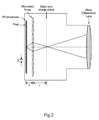
- FIG. 2 schematically illustrates an exemplary focused plenoptic camera.
- FIG. 3 illustrates radiance at the microlens plane captured by a conventional plenoptic camera.
- FIG. 4 illustrates radiance at the main image plane captured by a focused plenoptic camera.
- FIG. 5 illustrates radiance at the microlens plane captured by a focused plenoptic camera.
- FIG. 6 illustrates photographic images of a section of a microimage array captured by the sensor of a focused plenoptic camera and an exemplary operation by which regions of neighboring microimages become contiguous parts of a rendered image.
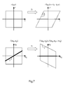
- FIG. 7 illustrates spatial domain shearing due to translation and frequency domain shearing due to translation.
- FIG. 8 illustrates a model for radiance captured by a focused plenoptic camera in which vertical columns of the 2D radiance are comprised of overlapping sections of a 1D function.
- FIG. 9 illustrates an exemplary extended slice technique.
- FIG. 10 illustrates a flow diagram according to an exemplary method including Fourier slice refocusing.
- FIG. 11 illustrates photographic images of a higher quality image rendering, a lower quality image rendering, and a contrast enhanced difference between the higher and lower image renderings showing patterns of artifacts in the lower quality image rendering.
- FIG. 12 illustrates photographic images of a five by three microimage of an exemplary plenoptic image of a seagull.
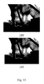
- FIG. 13 illustrates photographic images of an individual microimage of the exemplary plenoptic image of a seagull, an enlarged region of a spatially rendered image of the exemplary plenoptic image of a seagull, and an enlarged region of a Fourier rendered image of the exemplary plenoptic image of a seagull.
- FIG. 14 illustrates photographic images of a plenoptic image rendering at three different focal planes for both spatial full resolution rendering and full resolution Fourier slice rendering.
- FIG. 15 illustrates photographic images of an enlarged region of the same image rendered using both spatial full resolution rendering and full resolution Fourier slice rendering.
- FIG. 1 there is illustrated an exemplary conventional plenoptic camera including the optics thereof.
- Plenoptic cameras such as the example illustrated in FIG. 1 , are optical devices that capture radiance r(q,p) by multiplexing a 4D plenoptic function onto a 2D sensor.
- a traditional camera captures an image by physically integrating the intensities of all of the rays impinging on each sensor pixel
- a plenoptic camera instead captures rays (or thin bundles of rays) separately.
- FIG. 1 there is illustrated an exemplary conventional plenoptic camera including the optics thereof.
- Plenoptic cameras such as the example illustrated in FIG. 1 , are optical devices that capture radiance r(q,p) by multiplexing a 4D plenoptic function onto a 2D sensor.
- a plenoptic camera instead captures rays (or thin bundles of rays) separately.
- the conventional approach to separating, and then individually capturing, the rays in a scene is to put a microlens array on the main lens image plane (where the photosensor would be in a conventional camera) while placing the sensor itself some distance behind the microlens array.
- the photosensor is placed at a distance ⁇ behind the microlens array, where ⁇ is the focal distance of each individual microlens.
- the rays that converge at the microlens array will diverge as they propagate behind it.
- Individual pixels in the sensor now capture separate rays.
- the intensity as a function of position at the sensor represents the radiance as a function of direction at the position q of the pinhole.
- FIG. 2 there is illustrated an exemplary focused plenoptic camera including the optics thereof.
- each microlens forms a relay system with the main lens.
- FIGS. 3-5 illustrate how radiance is captured by conventional plenoptic cameras and by focused plenoptic cameras.
- FIG. 3 shows a phase space diagram of the radiance at the microlens plane as it is captured by a conventional plenoptic camera. In this case, each microimage comprises a vertical “stack” of pixels in the phase plane.
- FIG. 4 shows a phase space diagram of the radiance at the main (objective) lens image plane as captured by a focused plenoptic camera.
- each microimage comprises a slanted region of the phase plane.
- FIG. 5 shows the radiance captured by a focused plenoptic camera at the microlens plane. The rendering of an image from captured radiance will now be described.
- Eq. (1) reduces to a summation over all of the pixels in each microlens, resulting in a rendered image having one pixel per microimage in the captured radiance. This process is illustrated in FIG. 3 for one output pixel with the vertical arrow.
- a similar process can be applied to radiance captured by the focused plenoptic camera. However, in this case, the captured radiance must be interpreted differently.
- Eq. (1) is applied as shown in FIG. 4 . If captured radiance is represented in rectilinear form, rendering is performed at a slant, as shown in FIG. 5 . While focused radiance could be rendered with conventional techniques (shown by the vertical arrow in FIG. 5 , this would yield significantly lower resolution.
- FIG. 6 provides a further illustration of a focused plenoptic rendering process. Since a focused plenoptic camera is constructed as a relay imaging system, each microimage is a focused image that is a small sample of a larger complete image, namely the image at the main lens image plane. Neighboring microimages sample overlapping, shifted regions of the main lens image plane. Thus, interior regions of neighboring microimages become contiguous parts of the rendered image.
- Certain exemplary embodiments disclosed herein utilize Fourier slice refocusing of focused plenoptic data. It shall be appreciated that the techniques disclosed herein may be implemented through a variety of apparatuses, systems and processes, for example, through a computer including a data input for receiving input focused plenoptic image data, user inputs such as a keyboard or mouse, one or more memory devices configured to store the input focused plenoptic image data, one or more processors configured to process the stored focused plenoptic image data in accordance with one or more of the techniques disclosed herein, and a monitor configured to display visual output based upon rendered image information output by the one or more processors. It shall be appreciated that this configuration is but one example of image processing and rendering apparatuses and systems that may implement the techniques and processes disclosed herein.
- Certain exemplary embodiments provide Fourier slice refocusing of focused plenoptic image data based upon the Central Slice Theorem in the context of plenoptic imaging.
- Refocusing of a plenoptic image is accomplished by applying a translational transformation, equivalent to optical focusing, which changes the physical distance between the sensor and the main lens.
- the radiance transform for applying a translation is given by using Eq. (4) with the transformation described by Eq. (5):
- FIG. 9 illustrates an exemplary extended slice technique which may be performed on frequency domain plenoptic image data stored in array 910 .
- the frequency domain plenoptic image data may be captured by a conventional plenoptic camera or a focused plenoptic camera and may be transformed to the frequency domain using a variety of frequency domain transformation techniques.
- a central slice 911 and slice extensions 912 and 913 are taken from array 910 .
- the slice extensions 912 and 913 effectively wrap around the array 910 from the ends of central slice 911 .
- the central slice 911 and slice extensions 912 and 913 may then be configured to provide an extended slice 921 as illustrated in graph 920 .
- the extended slice 921 may be created by appending the slice extensions 912 and 913 to respective ends of central slice 911 .
- extended slice 921 may be accomplished using only data of the central slice 911 and slice extensions 912 and 913 , or by using additional non-sliced data from the array 910 .
- central slice 911 passes through the origin at a predetermined slope which provides two slice extensions. It shall be appreciated that this slope may be varied and that central slices with a different slopes may provide different lengths for the central slice and slice extensions or may provide a greater number of slice extensions by wrapping around the graph 910 multiple times.
- the illustrated slicing techniques may performed on frequency domain plenoptic image data stored in a variety of data structures and that the geometric representation of the array 910 as a two dimensional graph is non-limiting.
- FIG. 10 illustrates an exemplary method 100 implementing a Fourier slice refocusing technique.
- a preferred implementation of method 100 was written in C++ to run on single-core or shared-memory/multicore computers.
- the GNU Scientific Library was used for the FFT and inverse FFT computations. Computations were performed in double precision using complex numbers (the C++ std::complex ⁇ double> type). Arrays were stored using the Blitz++ multi-dimensional array library.
- OpenMP is used to parallelize the parallel portions of the algorithm (for example, x and y 1D FFTs on different rows, p and q FFTs and slicing on different rows of microimages, etc.). Those portions account for most of the algorithm, especially when multiple output images are being generated. It shall be appreciated that the foregoing specifics are exemplary and that a variety of other implementations of method 100 are contemplated.
- method 100 begins at operation 110 which selects the center portion of each microimage.
- the outer edges of microimages are often noisy, and thus are removed before further processing. From operation 110 method 100 proceeds to operation 120 .
- Operation 120 forms a 4D array from the input image and optionally some padding microimages around it.
- the four dimensions of the array are the x and y positions in the grid of microimages and the x and y positions within each microimage. Padding is added around the full set of microimages to avoid the result wrapping around at its edges (since the shear operation applied in the frequency domain would otherwise be periodic).
- the array of operation 120 as well as other arrays disclosed herein may be defined as a separate array for each color channel or a single array that contains all channels together.
- the array of operation 120 is non-limiting examples of data structures that may be stored in a non-transitory computer readable medium and that other types of data structures may be also utilizes provided that locations within the data structures can be individually identified to facilitate the slicing operations disclosed herein. Unless indicated to the contrary, the term array as related to data stored in a non-transitory computer readable medium is not limited to particular physical locations or addresses in such memory. From operation 120 method 100 proceeds to operation 130 .
- Operation 130 adds a normalization channel containing fully saturated values.
- the normalization channel is used to compensate for different numbers of microimages overlapping at different points in the output.
- the later division by the processed form of the normalization channel produces a weighted average of the microimages placed at each point. From operation 130 method 100 proceeds to operation 140 .
- Operation 140 applies a window function to reduce the effect of the outer portions of each microimage.
- the window function further removes the effects of noise at microimage edges, plus ensures that the output microimages blend more smoothly together. Applying the window to all four channels, including the normalization channel, reduces the weights of the outer portions of the microimages in the final averaging step. In the implementation, the outer 20% of each side of the microimage is reduced using a triangular window, applied separately (multiplicatively) to the x and y dimensions. From operation 140 method 100 proceeds to operation 150 .
- Operation 150 optionally pads each microimage to give more accuracy in the FFT output array. Zero-padding the input to a DFT is a an exemplary technique to obtain more frequency buckets in the output. Zero-padding gives a better interpolation accuracy of the frequencies than standard interpolation algorithms for smooth data. From operation 150 method 100 proceeds to operation 160
- Operation 160 applies a 4D Fast Fourier Transform (“FFT”) to the array. From operation 160 method 100 proceeds to operation 170 .
- FFT Fast Fourier Transform
- Operation 170 creates a 2D slice from the array, interpolating values as necessary.
- a 2D plane is extracted from the 4D array, wrapping around at the edges of the set of microimages but not at the edges of a single microimage. Interpolation in the array when selecting elements from microimages is further described below. In a preferred form the interpolation only takes place within a single microimage; the points sampled along the plane are chosen so that each point is exactly in a single microimage. From operation 170 method 100 proceeds to operation 180
- Operation 180 applies a 2D inverse FFT to the slice. From operation 180 method 100 proceeds to operation 190 .
- Operation 190 divides the other channels of the slice elementwise by the normalization channel. This step gives the weighted average mentioned above. Removing it would result in screen-door artifacts from the number of microimages summed at each output location varying over the image. The output image is then produced using the other channels' division results from this step.
- the normalization of operation 130 differs from embodiments which exclude normalization in several ways. More specifically, a new color channel is added to the input image and filled as if it was an all-white image. It is then filtered into a 4-d array just like the main image (including whatever masking, windowing, padding, etc. is done to the image), and processed as described below (i.e., frequency domain transform, slicing, inverse frequency domain transform) using the same steps as the rest of the image. After the inverse frequency domain transform step, the values of each pixel's other color channels are divided by that pixel's value in the normalization channel and the normalization channel is removed. The image is then stored or saved in memory. It shall be further appreciated that alternate techniques may be utilized to accomplish a similar effect as the normalization channel which may involve alternate computations.
- the foregoing exemplary implementation is preferred for off-line processing of a single plenoptic lightfield into multiple result images with different focal planes.
- the operations may be rearranged to share work between different output images.
- operations 110 , 120 , 130 and 140 and two of the four dimensions of the 4D FFT of operations 160 are performed once on the input image, while padding and the rest of the FFT are done as needed when building output images. All output images are generated together, allowing the work of steps 110 - 160 (which are focal-plane-independent) to be amortized across multiple outputs.
- the modified loop structure is the following:
- the reason for computing the FFTs for each microimage separately is to save memory, especially when input microimages have large amounts of padding inserted; they could be done in advance as an alternative with no change in results.
- the positions of pixels in the “slice” may not directly match up with the element indices of the 4D FFT.
- an interpolation algorithm may be used to obtain values for those pixels.
- An optional technique used was to zero-pad the input microimages before applying FFTs (but after the cross-microimage x and y FFTs; this ordering does not matter), leading to sine-based interpolation of the FFT results.
- FIG. 11 contains three versions of the same image: Image 1101 in FIG. 11 has a high-quality rendering using 8 ⁇ FFT interpolation and one-lobe Lanczos resampling. Image 1102 in FIG.
- Image 11 shows the same image rendered using only 2 ⁇ FFT interpolation and nearest-neighbor sampling.
- Image 1103 in FIG. 11 illustrates the difference between these images 1101 and 1102 , with contrast enhanced to show the pattern of artifacts created by the lower-quality sampling.
- 3 ⁇ FFT interpolation and nearest-neighbor sampling produces almost invisible artifacts: the losslessly-compressed output image must be examined carefully to find the few artifacts that exist.
- FIG. 12 Images were rendered spatially using an OpenGL-based rendering program.
- the specifications for each of the plenoptic images used are as follows.
- the complete plenoptic image measures 7240 ⁇ 5433 pixels (39 Mpix). It is comprised of 96 ⁇ 72 entire microimages over a range of 7176 ⁇ 5382 pixels, with partial microimages around the border. A square aperture was used in capturing the image, so microimages are approximately square.
- FIG. 13 shows a comparison of a raw microimage 1301 from the “seagull” example, with the same region of corresponding images of FIG. 12 .
- Image 1302 is rendered with the spatial full resolution rendering algorithm.
- Image 1303 is rendered with the full resolution Fourier slice algorithm. The portion of the image shown (the head of the seagull) is in focus when shifted by ⁇ 8.75 pixels (or, equivalently, with a patch size of ⁇ 8.75).
- the full resolution Fourier slice algorithm matches the spatial full resolution algorithm, and both rendering approaches match the microimage.
- FIG. 14 shows a series of images rendered from the same plenoptic image (the “Laura” image from http:/fwww.tgeorgiev.net).
- the images are rendered with the full resolution spatial rendering algorithm using shift values (patch sizes) of ⁇ 7.00, ⁇ 7.60, and ⁇ 10.00, which are focused on the background, midground, and foreground, respectively.
- the same planes were rendered using the full resolution Fourier slice algorithm, using slope (u) values of ⁇ 1/7.00, ⁇ 1/7.60, and ⁇ 1/10.00.
- the full resolution Fourier slice algorithm fully recapitulates the spatial rendering algorithm.
- the artifacts on foreground objects in the images are almost identical, while the patterns of artifacts in the backgrounds differ slightly (due to slightly different handling of interpolation and of microimage boundaries between the two approaches).
Abstract
Description
I(q)=∫q r(q,p)dp Eq. (1)
In the case of the conventional plenoptic camera, Eq. (1) reduces to a summation over all of the pixels in each microlens, resulting in a rendered image having one pixel per microimage in the captured radiance. This process is illustrated in
{circumflex over (I)}(ωq)=∫q I(q)e −i2πω
Substituting Eq. (1) into Eq. (2) gives Eq. (3):
{circumflex over (I)}(ωq)=∫∫q,p r(q,p)e −i2πω
Setting ωp=0 gives Eq. (4):
{circumflex over (I)}(ωq)={circumflex over (r)}(ωq,0) Eq. (4)
Thus, the Fourier transform of a 2D rendered image is the “DC” directional component of the Fourier transform of the 4D radiance, i.e., the slice where ωp=0.
Thus the transformed radiance r′ is given by r′(q,p)=r(q−tp,p). This transformation is illustrated in the upper portion of
{circumflex over (I)}(ωq)={circumflex over (r)}(ωq ,tω q) Eq. (6)
The Fourier slice for refocusing is shown with a grey line in the lower left portion of
r[m,n]=g[n+tm] Eq. (7)
where r is a two-dimensional M×N array and g is a one-dimensional tM array. This model is illustrated in
Where the notation
We can convert the transform to be taken over a range of tM using properties of the complex exponential of Equations (10) (11) and (12):
A slice can then be taken through
for i=0, . . . , t−1. The slice is then described by Equations (13), (14), (15) and (16):
as the full resolution rendering condition. Furthermore note that that the quantity n+tm simply cycles through the values 0, . . . , tM−1 modulo tM a total of N jt times as described by Equations (17), (18), (19), and (20):
In other words, we obtain the Fourier transform of g of length tM from the Fourier transform of r by concatenating together t different slices in f, displaced by N/t. Equivalently, if we let
-
- a. Generate a 4D array of windowed portions of the microimages (steps 110-140 described above).
- b. Apply 1D FFTs in the x and y directions (i.e., corresponding points in multiple microimages).
- c. For each microimage,
- i. Optionally, pad the microimage.
- ii. Apply 1D FFTs in the p and q directions (i.e., within a single microimage).
- iii. Interpolate all necessary points from the current microimage and place them into the correct positions in the
output 2D arrays.
- d. For each output image,
- i. Apply 1D inverse FFTs in the x and y directions.
- ii. Divide the other color channels of the image by the normalization channel.
- iii. Output the image into a file.
Claims (20)
Priority Applications (1)
| Application Number | Priority Date | Filing Date | Title |
|---|---|---|---|
| US14/585,380 US9538075B2 (en) | 2013-12-30 | 2014-12-30 | Frequency domain processing techniques for plenoptic images |
Applications Claiming Priority (2)
| Application Number | Priority Date | Filing Date | Title |
|---|---|---|---|
| US201361921868P | 2013-12-30 | 2013-12-30 | |
| US14/585,380 US9538075B2 (en) | 2013-12-30 | 2014-12-30 | Frequency domain processing techniques for plenoptic images |
Publications (2)
| Publication Number | Publication Date |
|---|---|
| US20150187047A1 US20150187047A1 (en) | 2015-07-02 |
| US9538075B2 true US9538075B2 (en) | 2017-01-03 |
Family
ID=53482356
Family Applications (1)
| Application Number | Title | Priority Date | Filing Date |
|---|---|---|---|
| US14/585,380 Active US9538075B2 (en) | 2013-12-30 | 2014-12-30 | Frequency domain processing techniques for plenoptic images |
Country Status (1)
| Country | Link |
|---|---|
| US (1) | US9538075B2 (en) |
Cited By (1)
| Publication number | Priority date | Publication date | Assignee | Title |
|---|---|---|---|---|
| US20230333310A1 (en) * | 2016-07-15 | 2023-10-19 | Light Field Lab, Inc. | Holographic superimposition of real world plenoptic opacity modulation through transparent waveguide arrays for light field, virtual and augmented reality |
Families Citing this family (2)
| Publication number | Priority date | Publication date | Assignee | Title |
|---|---|---|---|---|
| US9613417B2 (en) * | 2015-03-04 | 2017-04-04 | Ricoh Company, Ltd. | Calibration of plenoptic imaging systems using fourier transform |
| WO2018209703A1 (en) * | 2017-05-19 | 2018-11-22 | Shanghaitech University | Method and system for snapshot multi-spectral light field imaging |
Citations (65)
| Publication number | Priority date | Publication date | Assignee | Title |
|---|---|---|---|---|
| US725567A (en) | 1902-09-25 | 1903-04-14 | Frederic E Ives | Parallax stereogram and process of making same. |
| US2039648A (en) | 1933-05-06 | 1936-05-05 | Perser Corp | Camera for making parallax panoramagrams |
| US3985419A (en) | 1970-10-05 | 1976-10-12 | Canon Kabushiki Kaisha | Method of making a synthetic focused image hologram |
| US4180313A (en) | 1977-03-11 | 1979-12-25 | Fuji Photo Film Co., Ltd. | Stereoscopic camera |
| US4193093A (en) | 1978-08-03 | 1980-03-11 | The United States Of America As Represented By The Secretary Of The Navy | CCD camera interface circuit |
| US4732453A (en) | 1984-12-10 | 1988-03-22 | Integrated Images, Inc. | Integral photography apparatus and method of forming same |
| US4849782A (en) | 1985-06-28 | 1989-07-18 | Canon Kabushiki Kaisha | Focus detecting device |
| US5076687A (en) | 1990-08-28 | 1991-12-31 | Massachusetts Institute Of Technology | Optical ranging apparatus |
| US5361127A (en) | 1992-08-07 | 1994-11-01 | Hughes Aircraft Company | Multi-image single sensor depth recovery system |
| US5400093A (en) | 1992-12-28 | 1995-03-21 | U.S. Philips Corporation | Image projection system with autofocusing |
| US5659420A (en) | 1993-09-30 | 1997-08-19 | Kabushiki Kaisha Komatsu Seisakusho | Confocal optical apparatus |
| US5729011A (en) | 1995-02-24 | 1998-03-17 | Olympus Optical Co., Ltd. | Spectroscopic apparatus and spectroscopic image recording apparatus |
| US5946077A (en) | 1994-09-06 | 1999-08-31 | Herman D. Mims | Method and apparatus for improved three dimensional photography |
| US6097541A (en) | 1997-01-31 | 2000-08-01 | De Montfort University | Lens arrangements |
| US6137937A (en) | 1998-04-27 | 2000-10-24 | Nippon Hoso Kyokai | Autostereoscopic image apparatus |
| WO2001037025A1 (en) | 1999-11-16 | 2001-05-25 | Agilent Technologies, Inc. | Confocal imaging |
| US6268846B1 (en) | 1998-06-22 | 2001-07-31 | Adobe Systems Incorporated | 3D graphics based on images and morphing |
| US20010012149A1 (en) | 1997-10-30 | 2001-08-09 | Shawn-Yu Lin | Optical elements comprising photonic crystals and applications thereof |
| US6301416B1 (en) | 1998-10-09 | 2001-10-09 | Nippon Hoso Kyokai | Optical three-dimensional imaging device which uses an integral photography technique |
| US20010050813A1 (en) | 1996-05-09 | 2001-12-13 | Pierre Allio | Autostereoscopic imaging device and system comprising it |
| US6339506B1 (en) | 1998-11-06 | 2002-01-15 | Oni Systems Corp. | Microlens array with spatially varying optical property |
| US6351269B1 (en) | 1998-04-17 | 2002-02-26 | Adobe Systems Incorporated | Multiple image morphing |
| US20020140835A1 (en) | 2001-03-27 | 2002-10-03 | Silverstein D. Amnon | Single sensor chip digital stereo camera |
| US6476805B1 (en) | 1999-12-23 | 2002-11-05 | Microsoft Corporation | Techniques for spatial displacement estimation and multi-resolution operations on light fields |
| US20030231255A1 (en) | 2002-06-12 | 2003-12-18 | Eastman Kodak Company | Imaging using silver halide films with micro-lens capture, scanning and digital reconstruction |
| US6738533B1 (en) | 2000-03-29 | 2004-05-18 | Microsoft Corporation | Minimum sampling rate and minimum sampling curve for image-based rendering |
| US20040114807A1 (en) | 2002-12-13 | 2004-06-17 | Dan Lelescu | Statistical representation and coding of light field data |
| US20040223214A1 (en) | 2003-05-09 | 2004-11-11 | 3M Innovative Properties Company | Scanning laser microscope with wavefront sensor |
| US20050088714A1 (en) | 1997-07-08 | 2005-04-28 | Kremen Stanley H. | Method for creating a holographic screen that reconstructs uniformly magnified three-dimensional images from projected integral photographs |
| US20050122418A1 (en) | 2003-12-03 | 2005-06-09 | Canon Kabushiki Kaisha | Solid state image pickup device, method for producing the same, and image pickup system comprising the solid state image pickup device |
| EP1548481A1 (en) | 2002-09-30 | 2005-06-29 | Japan Science and Technology Agency | Cofocal microscope, fluorescence measuring method and polarized light measuring metod using cofocal microscope |
| US7054067B2 (en) | 2003-05-27 | 2006-05-30 | Nippon Hoso Kyokai | Three-dimensional image optical system |
| WO2006057838A1 (en) | 2004-11-24 | 2006-06-01 | Kremen Stanley H | Modular integral magnifier |
| WO2007115281A1 (en) | 2006-04-04 | 2007-10-11 | Adobe Systems, Incorporated | Improved plenoptic camera |
| US20070252074A1 (en) * | 2004-10-01 | 2007-11-01 | The Board Of Trustees Of The Leland Stanford Junio | Imaging Arrangements and Methods Therefor |
| US20080152215A1 (en) | 2006-12-26 | 2008-06-26 | Kenichi Horie | Coding method, electronic camera, recording medium storing coded program, and decoding method |
| US20080165270A1 (en) | 2007-01-09 | 2008-07-10 | Sony Corporation | Image pickup apparatus |
| US20080187305A1 (en) * | 2007-02-06 | 2008-08-07 | Ramesh Raskar | 4D light field cameras |
| US20080193026A1 (en) | 2007-02-09 | 2008-08-14 | Kenichi Horie | Decoding method, decoding apparatus, storage medium in which decoding program is stored, and electronic camera |
| US20090041448A1 (en) | 2007-08-06 | 2009-02-12 | Georgiev Todor G | Method and Apparatus for Radiance Capture by Multiplexing in the Frequency Domain |
| US20090140131A1 (en) | 2005-06-23 | 2009-06-04 | Nikon Corporation | Image input apparatus, photodetection apparatus, and image synthesis method |
| US20090185801A1 (en) * | 2008-01-23 | 2009-07-23 | Georgiev Todor G | Methods and Apparatus for Full-Resolution Light-Field Capture and Rendering |
| US20100026852A1 (en) | 2006-02-07 | 2010-02-04 | Yi-Ren Ng | Variable imaging arrangements and methods therefor |
| US20100085468A1 (en) | 2008-10-06 | 2010-04-08 | Park Byung-Kwan | Apparatus and method of capturing image |
| US20110080491A1 (en) | 2008-06-10 | 2011-04-07 | Valter Drazic | Multi-image capture system with improved depth image resolution |
| US20120043963A1 (en) * | 2009-04-27 | 2012-02-23 | Aspect Magnet Technologies Ltd. | Imaging Device For Three Dimensional Anatomical And Functional Imaging And Methods Thereof |
| US8155456B2 (en) | 2008-04-29 | 2012-04-10 | Adobe Systems Incorporated | Method and apparatus for block-based compression of light-field images |
| US8189065B2 (en) | 2008-01-23 | 2012-05-29 | Adobe Systems Incorporated | Methods and apparatus for full-resolution light-field capture and rendering |
| US8189089B1 (en) | 2009-01-20 | 2012-05-29 | Adobe Systems Incorporated | Methods and apparatus for reducing plenoptic camera artifacts |
| US20120140024A1 (en) | 2010-12-03 | 2012-06-07 | Fly's Eye Imaging, LLC | Method of displaying an enhanced three-dimensional images |
| US8228417B1 (en) | 2009-07-15 | 2012-07-24 | Adobe Systems Incorporated | Focused plenoptic camera employing different apertures or filtering at different microlenses |
| US8244058B1 (en) | 2008-05-30 | 2012-08-14 | Adobe Systems Incorporated | Method and apparatus for managing artifacts in frequency domain processing of light-field images |
| US8290358B1 (en) | 2007-06-25 | 2012-10-16 | Adobe Systems Incorporated | Methods and apparatus for light-field imaging |
| US8315476B1 (en) | 2009-01-20 | 2012-11-20 | Adobe Systems Incorporated | Super-resolution with the focused plenoptic camera |
| US8345144B1 (en) | 2009-07-15 | 2013-01-01 | Adobe Systems Incorporated | Methods and apparatus for rich image capture with focused plenoptic cameras |
| US8358366B1 (en) | 2010-05-28 | 2013-01-22 | Adobe Systems Incorporate | Methods and apparatus for high-speed digital imaging |
| US8400555B1 (en) | 2009-12-01 | 2013-03-19 | Adobe Systems Incorporated | Focused plenoptic camera employing microlenses with different focal lengths |
| US8625931B2 (en) | 2010-09-03 | 2014-01-07 | Adobe Systems Incorporated | Light space graphical model in shape from shading |
| US8665341B2 (en) | 2010-08-27 | 2014-03-04 | Adobe Systems Incorporated | Methods and apparatus for rendering output images with simulated artistic effects from focused plenoptic camera data |
| US8724000B2 (en) | 2010-08-27 | 2014-05-13 | Adobe Systems Incorporated | Methods and apparatus for super-resolution in integral photography |
| US8749694B2 (en) | 2010-08-27 | 2014-06-10 | Adobe Systems Incorporated | Methods and apparatus for rendering focused plenoptic camera data using super-resolved demosaicing |
| US8803918B2 (en) | 2010-08-27 | 2014-08-12 | Adobe Systems Incorporated | Methods and apparatus for calibrating focused plenoptic camera data |
| US8817015B2 (en) | 2010-03-03 | 2014-08-26 | Adobe Systems Incorporated | Methods, apparatus, and computer-readable storage media for depth-based rendering of focused plenoptic camera data |
| US20140239071A1 (en) * | 2013-02-28 | 2014-08-28 | Hand Held Products, Inc. | Indicia reading terminals and methods for decoding decodable indicia employing light field imaging |
| US20140327566A1 (en) * | 2012-05-09 | 2014-11-06 | Stmicroelectronics S.R.L. | Method and devices for processing radar signals |
-
2014
- 2014-12-30 US US14/585,380 patent/US9538075B2/en active Active
Patent Citations (82)
| Publication number | Priority date | Publication date | Assignee | Title |
|---|---|---|---|---|
| US725567A (en) | 1902-09-25 | 1903-04-14 | Frederic E Ives | Parallax stereogram and process of making same. |
| US2039648A (en) | 1933-05-06 | 1936-05-05 | Perser Corp | Camera for making parallax panoramagrams |
| US3985419A (en) | 1970-10-05 | 1976-10-12 | Canon Kabushiki Kaisha | Method of making a synthetic focused image hologram |
| US4180313A (en) | 1977-03-11 | 1979-12-25 | Fuji Photo Film Co., Ltd. | Stereoscopic camera |
| US4193093A (en) | 1978-08-03 | 1980-03-11 | The United States Of America As Represented By The Secretary Of The Navy | CCD camera interface circuit |
| US4732453A (en) | 1984-12-10 | 1988-03-22 | Integrated Images, Inc. | Integral photography apparatus and method of forming same |
| US4849782A (en) | 1985-06-28 | 1989-07-18 | Canon Kabushiki Kaisha | Focus detecting device |
| US5076687A (en) | 1990-08-28 | 1991-12-31 | Massachusetts Institute Of Technology | Optical ranging apparatus |
| US5361127A (en) | 1992-08-07 | 1994-11-01 | Hughes Aircraft Company | Multi-image single sensor depth recovery system |
| US5400093A (en) | 1992-12-28 | 1995-03-21 | U.S. Philips Corporation | Image projection system with autofocusing |
| US5659420A (en) | 1993-09-30 | 1997-08-19 | Kabushiki Kaisha Komatsu Seisakusho | Confocal optical apparatus |
| US5946077A (en) | 1994-09-06 | 1999-08-31 | Herman D. Mims | Method and apparatus for improved three dimensional photography |
| US5729011A (en) | 1995-02-24 | 1998-03-17 | Olympus Optical Co., Ltd. | Spectroscopic apparatus and spectroscopic image recording apparatus |
| US20010050813A1 (en) | 1996-05-09 | 2001-12-13 | Pierre Allio | Autostereoscopic imaging device and system comprising it |
| US6097541A (en) | 1997-01-31 | 2000-08-01 | De Montfort University | Lens arrangements |
| US20050088714A1 (en) | 1997-07-08 | 2005-04-28 | Kremen Stanley H. | Method for creating a holographic screen that reconstructs uniformly magnified three-dimensional images from projected integral photographs |
| US20010012149A1 (en) | 1997-10-30 | 2001-08-09 | Shawn-Yu Lin | Optical elements comprising photonic crystals and applications thereof |
| US6351269B1 (en) | 1998-04-17 | 2002-02-26 | Adobe Systems Incorporated | Multiple image morphing |
| US6137937A (en) | 1998-04-27 | 2000-10-24 | Nippon Hoso Kyokai | Autostereoscopic image apparatus |
| US6268846B1 (en) | 1998-06-22 | 2001-07-31 | Adobe Systems Incorporated | 3D graphics based on images and morphing |
| US6301416B1 (en) | 1998-10-09 | 2001-10-09 | Nippon Hoso Kyokai | Optical three-dimensional imaging device which uses an integral photography technique |
| US6339506B1 (en) | 1998-11-06 | 2002-01-15 | Oni Systems Corp. | Microlens array with spatially varying optical property |
| US6838650B1 (en) | 1999-11-16 | 2005-01-04 | Agilent Technologies, Inc. | Confocal imaging |
| WO2001037025A1 (en) | 1999-11-16 | 2001-05-25 | Agilent Technologies, Inc. | Confocal imaging |
| US6476805B1 (en) | 1999-12-23 | 2002-11-05 | Microsoft Corporation | Techniques for spatial displacement estimation and multi-resolution operations on light fields |
| US6738533B1 (en) | 2000-03-29 | 2004-05-18 | Microsoft Corporation | Minimum sampling rate and minimum sampling curve for image-based rendering |
| US20020140835A1 (en) | 2001-03-27 | 2002-10-03 | Silverstein D. Amnon | Single sensor chip digital stereo camera |
| US20030231255A1 (en) | 2002-06-12 | 2003-12-18 | Eastman Kodak Company | Imaging using silver halide films with micro-lens capture, scanning and digital reconstruction |
| EP1548481A1 (en) | 2002-09-30 | 2005-06-29 | Japan Science and Technology Agency | Cofocal microscope, fluorescence measuring method and polarized light measuring metod using cofocal microscope |
| US20040114807A1 (en) | 2002-12-13 | 2004-06-17 | Dan Lelescu | Statistical representation and coding of light field data |
| US20040223214A1 (en) | 2003-05-09 | 2004-11-11 | 3M Innovative Properties Company | Scanning laser microscope with wavefront sensor |
| US7054067B2 (en) | 2003-05-27 | 2006-05-30 | Nippon Hoso Kyokai | Three-dimensional image optical system |
| US20050122418A1 (en) | 2003-12-03 | 2005-06-09 | Canon Kabushiki Kaisha | Solid state image pickup device, method for producing the same, and image pickup system comprising the solid state image pickup device |
| US20070252074A1 (en) * | 2004-10-01 | 2007-11-01 | The Board Of Trustees Of The Leland Stanford Junio | Imaging Arrangements and Methods Therefor |
| WO2006057838A1 (en) | 2004-11-24 | 2006-06-01 | Kremen Stanley H | Modular integral magnifier |
| US20090140131A1 (en) | 2005-06-23 | 2009-06-04 | Nikon Corporation | Image input apparatus, photodetection apparatus, and image synthesis method |
| US7732744B2 (en) | 2005-06-23 | 2010-06-08 | Nikon Corporation | Image input apparatus, photodetection apparatus, and image synthesis method |
| US20100026852A1 (en) | 2006-02-07 | 2010-02-04 | Yi-Ren Ng | Variable imaging arrangements and methods therefor |
| US8238738B2 (en) | 2006-04-04 | 2012-08-07 | Adobe Systems Incorporated | Plenoptic camera |
| US7620309B2 (en) | 2006-04-04 | 2009-11-17 | Adobe Systems, Incorporated | Plenoptic camera |
| WO2007115281A1 (en) | 2006-04-04 | 2007-10-11 | Adobe Systems, Incorporated | Improved plenoptic camera |
| US20080152215A1 (en) | 2006-12-26 | 2008-06-26 | Kenichi Horie | Coding method, electronic camera, recording medium storing coded program, and decoding method |
| US20080165270A1 (en) | 2007-01-09 | 2008-07-10 | Sony Corporation | Image pickup apparatus |
| US7792423B2 (en) | 2007-02-06 | 2010-09-07 | Mitsubishi Electric Research Laboratories, Inc. | 4D light field cameras |
| US20080187305A1 (en) * | 2007-02-06 | 2008-08-07 | Ramesh Raskar | 4D light field cameras |
| US20100265386A1 (en) | 2007-02-06 | 2010-10-21 | Ramesh Raskar | 4D Light Field Cameras |
| US20080193026A1 (en) | 2007-02-09 | 2008-08-14 | Kenichi Horie | Decoding method, decoding apparatus, storage medium in which decoding program is stored, and electronic camera |
| US8290358B1 (en) | 2007-06-25 | 2012-10-16 | Adobe Systems Incorporated | Methods and apparatus for light-field imaging |
| US20090041448A1 (en) | 2007-08-06 | 2009-02-12 | Georgiev Todor G | Method and Apparatus for Radiance Capture by Multiplexing in the Frequency Domain |
| US20090041381A1 (en) | 2007-08-06 | 2009-02-12 | Georgiev Todor G | Method and Apparatus for Radiance Processing by Demultiplexing in the Frequency Domain |
| US8126323B2 (en) | 2007-08-06 | 2012-02-28 | Adobe Systems Incorporated | Method and apparatus for radiance capture by multiplexing in the frequency domain |
| US8559756B2 (en) | 2007-08-06 | 2013-10-15 | Adobe Systems Incorporated | Radiance processing by demultiplexing in the frequency domain |
| US20090185801A1 (en) * | 2008-01-23 | 2009-07-23 | Georgiev Todor G | Methods and Apparatus for Full-Resolution Light-Field Capture and Rendering |
| US8379105B2 (en) | 2008-01-23 | 2013-02-19 | Adobe Systems Incorporated | Methods and apparatus for full-resolution light-field capture and rendering |
| US8160439B2 (en) | 2008-01-23 | 2012-04-17 | Adobe Systems Incorporated | Methods and apparatus for full-resolution light-field capture and rendering |
| US8189065B2 (en) | 2008-01-23 | 2012-05-29 | Adobe Systems Incorporated | Methods and apparatus for full-resolution light-field capture and rendering |
| US8380060B2 (en) | 2008-01-23 | 2013-02-19 | Adobe Systems Incorporated | Methods and apparatus for full-resolution light-field capture and rendering |
| US8401316B2 (en) | 2008-04-29 | 2013-03-19 | Adobe Systems Incorporated | Method and apparatus for block-based compression of light-field images |
| US8155456B2 (en) | 2008-04-29 | 2012-04-10 | Adobe Systems Incorporated | Method and apparatus for block-based compression of light-field images |
| US8244058B1 (en) | 2008-05-30 | 2012-08-14 | Adobe Systems Incorporated | Method and apparatus for managing artifacts in frequency domain processing of light-field images |
| US8611693B2 (en) * | 2008-05-30 | 2013-12-17 | Adobe Systems Incorporated | Managing artifacts in frequency domain processing of light-field images |
| US8111320B2 (en) | 2008-06-10 | 2012-02-07 | Thomson Licensing | Multi-image capture system with improved depth image resolution |
| US20110080491A1 (en) | 2008-06-10 | 2011-04-07 | Valter Drazic | Multi-image capture system with improved depth image resolution |
| US20100085468A1 (en) | 2008-10-06 | 2010-04-08 | Park Byung-Kwan | Apparatus and method of capturing image |
| US8189089B1 (en) | 2009-01-20 | 2012-05-29 | Adobe Systems Incorporated | Methods and apparatus for reducing plenoptic camera artifacts |
| US8315476B1 (en) | 2009-01-20 | 2012-11-20 | Adobe Systems Incorporated | Super-resolution with the focused plenoptic camera |
| US20120043963A1 (en) * | 2009-04-27 | 2012-02-23 | Aspect Magnet Technologies Ltd. | Imaging Device For Three Dimensional Anatomical And Functional Imaging And Methods Thereof |
| US8228417B1 (en) | 2009-07-15 | 2012-07-24 | Adobe Systems Incorporated | Focused plenoptic camera employing different apertures or filtering at different microlenses |
| US8345144B1 (en) | 2009-07-15 | 2013-01-01 | Adobe Systems Incorporated | Methods and apparatus for rich image capture with focused plenoptic cameras |
| US8471920B2 (en) | 2009-07-15 | 2013-06-25 | Adobe Systems Incorporated | Focused plenoptic camera employing different apertures or filtering at different microlenses |
| US8400555B1 (en) | 2009-12-01 | 2013-03-19 | Adobe Systems Incorporated | Focused plenoptic camera employing microlenses with different focal lengths |
| US8817015B2 (en) | 2010-03-03 | 2014-08-26 | Adobe Systems Incorporated | Methods, apparatus, and computer-readable storage media for depth-based rendering of focused plenoptic camera data |
| US8358366B1 (en) | 2010-05-28 | 2013-01-22 | Adobe Systems Incorporate | Methods and apparatus for high-speed digital imaging |
| US8665341B2 (en) | 2010-08-27 | 2014-03-04 | Adobe Systems Incorporated | Methods and apparatus for rendering output images with simulated artistic effects from focused plenoptic camera data |
| US8724000B2 (en) | 2010-08-27 | 2014-05-13 | Adobe Systems Incorporated | Methods and apparatus for super-resolution in integral photography |
| US8749694B2 (en) | 2010-08-27 | 2014-06-10 | Adobe Systems Incorporated | Methods and apparatus for rendering focused plenoptic camera data using super-resolved demosaicing |
| US8803918B2 (en) | 2010-08-27 | 2014-08-12 | Adobe Systems Incorporated | Methods and apparatus for calibrating focused plenoptic camera data |
| US8625931B2 (en) | 2010-09-03 | 2014-01-07 | Adobe Systems Incorporated | Light space graphical model in shape from shading |
| US8675993B2 (en) | 2010-09-03 | 2014-03-18 | Adobe Systems Incorporated | Methods and apparatus for patch-based shape from shading |
| US20120140024A1 (en) | 2010-12-03 | 2012-06-07 | Fly's Eye Imaging, LLC | Method of displaying an enhanced three-dimensional images |
| US20140327566A1 (en) * | 2012-05-09 | 2014-11-06 | Stmicroelectronics S.R.L. | Method and devices for processing radar signals |
| US20140239071A1 (en) * | 2013-02-28 | 2014-08-28 | Hand Held Products, Inc. | Indicia reading terminals and methods for decoding decodable indicia employing light field imaging |
Non-Patent Citations (5)
| Title |
|---|
| Fourier Lumsdaine, Andrew et al., "Fourier Analysis of the Focused Plenoptic Camera", SPIE-IS&T Eletronic Imaging, SPIE vol. 8667 Devices, 2013. |
| Georgiev et al. ("Focused plenoptic camera and rendering," Journal of Electronic Imaging 19(2), Apr.-Jun. 2010). * |
| Lumsdaine et al. ("The focused plenoptic camera," International Conference on Computational Photography, Apr. 2009). * |
| Ng, Ren ("Fourier Slice Photography," Proceedings of ACM SIGGRAPH, vol. 24, Issue 3, Jul. 2005, pp. 735-744)-[Fig. 8 and Sect. 6.1: Algorithm]. * |
| Perez et al. ("Fourier slice super-resolution in plenoptic cameras," IEEE International Conference on Computational Photography, Apr. 28-29, 2012). * |
Cited By (1)
| Publication number | Priority date | Publication date | Assignee | Title |
|---|---|---|---|---|
| US20230333310A1 (en) * | 2016-07-15 | 2023-10-19 | Light Field Lab, Inc. | Holographic superimposition of real world plenoptic opacity modulation through transparent waveguide arrays for light field, virtual and augmented reality |
Also Published As
| Publication number | Publication date |
|---|---|
| US20150187047A1 (en) | 2015-07-02 |
Similar Documents
| Publication | Publication Date | Title |
|---|---|---|
| Wronski et al. | Handheld multi-frame super-resolution | |
| US10015469B2 (en) | Image blur based on 3D depth information | |
| US9497437B2 (en) | Digital refocusing method | |
| US8405742B2 (en) | Processing images having different focus | |
| KR20200049833A (en) | Depth estimation methods and apparatus, electronic devices, programs and media | |
| Yu et al. | An analysis of color demosaicing in plenoptic cameras | |
| ES2847348T3 (en) | Procedure and apparatus for tracking an object | |
| JP2011022796A (en) | Image processing method and image processor | |
| US20160171669A1 (en) | Using depth for recovering missing information in an image | |
| JP6619034B2 (en) | Homography correction | |
| CN105721768B (en) | Method and apparatus for generating a suitable slice image from a focus stack | |
| US20150054986A1 (en) | Image processing apparatus, imaging apparatus, and image processing method | |
| US20160148387A1 (en) | Apparatus, system, and method for processing information and program for the same | |
| RU2018113713A (en) | LIGHT FIELD DATA REPRESENTATION | |
| US9538075B2 (en) | Frequency domain processing techniques for plenoptic images | |
| EP3208773B1 (en) | Disparity-to-depth calibration for plenoptic imaging systems | |
| JP6234401B2 (en) | Image processing apparatus, imaging apparatus, image processing method, and program | |
| US20170299432A1 (en) | Spectroscopic data processing apparatus, image capturing apparatus, spectroscopic data processing method, and storage medium for storing spectroscopic data processing program | |
| JP6968895B2 (en) | Method and optical system to acquire tomographic distribution of electromagnetic field crest | |
| JP6867645B2 (en) | Image processing equipment, methods, and programs | |
| JP2013222245A (en) | Image sharpness evaluation device | |
| Rafinazari et al. | Demosaicking algorithm for the Kodak-RGBW color filter array | |
| JP2019502277A5 (en) | ||
| Lumsdaine et al. | Fourier analysis of the focused plenoptic camera | |
| Pérez et al. | Super-resolved Fourier-slice refocusing in plenoptic cameras |
Legal Events
| Date | Code | Title | Description |
|---|---|---|---|
| AS | Assignment |
Owner name: INDIANA UNIVERSITY RESEARCH & TECHNOLOGY CORPORATI Free format text: ASSIGNMENT OF ASSIGNORS INTEREST;ASSIGNORS:LUMSDAINE, ANDREW;LIN, LILI;ZHOU, YUDUO;SIGNING DATES FROM 20150303 TO 20150422;REEL/FRAME:035482/0226 Owner name: INDIANA UNIVERSITY RESEARCH & TECHNOLOGY CORPORATI Free format text: ASSIGNMENT OF ASSIGNORS INTEREST;ASSIGNOR:WILLCOCK, JEREMIAH;REEL/FRAME:035482/0262 Effective date: 20150408 |
|
| STCF | Information on status: patent grant |
Free format text: PATENTED CASE |
|
| MAFP | Maintenance fee payment |
Free format text: PAYMENT OF MAINTENANCE FEE, 4TH YR, SMALL ENTITY (ORIGINAL EVENT CODE: M2551); ENTITY STATUS OF PATENT OWNER: SMALL ENTITY Year of fee payment: 4 |