US9518963B2 - Electrospray emitter assemblies for microfluidic chromatography apparatus - Google Patents
Electrospray emitter assemblies for microfluidic chromatography apparatus Download PDFInfo
- Publication number
- US9518963B2 US9518963B2 US14/131,162 US201214131162A US9518963B2 US 9518963 B2 US9518963 B2 US 9518963B2 US 201214131162 A US201214131162 A US 201214131162A US 9518963 B2 US9518963 B2 US 9518963B2
- Authority
- US
- United States
- Prior art keywords
- emitter
- microfluidic
- tube
- electrically conductive
- substrate
- Prior art date
- Legal status (The legal status is an assumption and is not a legal conclusion. Google has not performed a legal analysis and makes no representation as to the accuracy of the status listed.)
- Active, expires
Links
Images


Classifications
-
- G—PHYSICS
- G01—MEASURING; TESTING
- G01N—INVESTIGATING OR ANALYSING MATERIALS BY DETERMINING THEIR CHEMICAL OR PHYSICAL PROPERTIES
- G01N30/00—Investigating or analysing materials by separation into components using adsorption, absorption or similar phenomena or using ion-exchange, e.g. chromatography or field flow fractionation
- G01N30/02—Column chromatography
- G01N30/60—Construction of the column
- G01N30/6004—Construction of the column end pieces
- G01N30/6026—Fluid seals
-
- G—PHYSICS
- G01—MEASURING; TESTING
- G01N—INVESTIGATING OR ANALYSING MATERIALS BY DETERMINING THEIR CHEMICAL OR PHYSICAL PROPERTIES
- G01N30/00—Investigating or analysing materials by separation into components using adsorption, absorption or similar phenomena or using ion-exchange, e.g. chromatography or field flow fractionation
- G01N30/02—Column chromatography
- G01N30/62—Detectors specially adapted therefor
- G01N30/72—Mass spectrometers
-
- B—PERFORMING OPERATIONS; TRANSPORTING
- B01—PHYSICAL OR CHEMICAL PROCESSES OR APPARATUS IN GENERAL
- B01D—SEPARATION
- B01D15/00—Separating processes involving the treatment of liquids with solid sorbents; Apparatus therefor
- B01D15/08—Selective adsorption, e.g. chromatography
- B01D15/10—Selective adsorption, e.g. chromatography characterised by constructional or operational features
- B01D15/22—Selective adsorption, e.g. chromatography characterised by constructional or operational features relating to the construction of the column
-
- B—PERFORMING OPERATIONS; TRANSPORTING
- B05—SPRAYING OR ATOMISING IN GENERAL; APPLYING FLUENT MATERIALS TO SURFACES, IN GENERAL
- B05B—SPRAYING APPARATUS; ATOMISING APPARATUS; NOZZLES
- B05B5/00—Electrostatic spraying apparatus; Spraying apparatus with means for charging the spray electrically; Apparatus for spraying liquids or other fluent materials by other electric means
- B05B5/16—Arrangements for supplying liquids or other fluent material
-
- G—PHYSICS
- G01—MEASURING; TESTING
- G01N—INVESTIGATING OR ANALYSING MATERIALS BY DETERMINING THEIR CHEMICAL OR PHYSICAL PROPERTIES
- G01N30/00—Investigating or analysing materials by separation into components using adsorption, absorption or similar phenomena or using ion-exchange, e.g. chromatography or field flow fractionation
- G01N30/02—Column chromatography
- G01N30/60—Construction of the column
- G01N30/6004—Construction of the column end pieces
- G01N30/603—Construction of the column end pieces retaining the stationary phase, e.g. Frits
-
- G—PHYSICS
- G01—MEASURING; TESTING
- G01N—INVESTIGATING OR ANALYSING MATERIALS BY DETERMINING THEIR CHEMICAL OR PHYSICAL PROPERTIES
- G01N30/00—Investigating or analysing materials by separation into components using adsorption, absorption or similar phenomena or using ion-exchange, e.g. chromatography or field flow fractionation
- G01N30/02—Column chromatography
- G01N30/60—Construction of the column
- G01N30/6052—Construction of the column body
-
- B—PERFORMING OPERATIONS; TRANSPORTING
- B01—PHYSICAL OR CHEMICAL PROCESSES OR APPARATUS IN GENERAL
- B01D—SEPARATION
- B01D15/00—Separating processes involving the treatment of liquids with solid sorbents; Apparatus therefor
- B01D15/08—Selective adsorption, e.g. chromatography
- B01D15/10—Selective adsorption, e.g. chromatography characterised by constructional or operational features
- B01D15/18—Selective adsorption, e.g. chromatography characterised by constructional or operational features relating to flow patterns
- B01D15/1864—Selective adsorption, e.g. chromatography characterised by constructional or operational features relating to flow patterns using two or more columns
- B01D15/1871—Selective adsorption, e.g. chromatography characterised by constructional or operational features relating to flow patterns using two or more columns placed in series
-
- F—MECHANICAL ENGINEERING; LIGHTING; HEATING; WEAPONS; BLASTING
- F16—ENGINEERING ELEMENTS AND UNITS; GENERAL MEASURES FOR PRODUCING AND MAINTAINING EFFECTIVE FUNCTIONING OF MACHINES OR INSTALLATIONS; THERMAL INSULATION IN GENERAL
- F16L—PIPES; JOINTS OR FITTINGS FOR PIPES; SUPPORTS FOR PIPES, CABLES OR PROTECTIVE TUBING; MEANS FOR THERMAL INSULATION IN GENERAL
- F16L19/00—Joints in which sealing surfaces are pressed together by means of a member, e.g. a swivel nut, screwed on or into one of the joint parts
- F16L19/02—Pipe ends provided with collars or flanges, integral with the pipe or not, pressed together by a screwed member
-
- F—MECHANICAL ENGINEERING; LIGHTING; HEATING; WEAPONS; BLASTING
- F16—ENGINEERING ELEMENTS AND UNITS; GENERAL MEASURES FOR PRODUCING AND MAINTAINING EFFECTIVE FUNCTIONING OF MACHINES OR INSTALLATIONS; THERMAL INSULATION IN GENERAL
- F16L—PIPES; JOINTS OR FITTINGS FOR PIPES; SUPPORTS FOR PIPES, CABLES OR PROTECTIVE TUBING; MEANS FOR THERMAL INSULATION IN GENERAL
- F16L9/00—Rigid pipes
- F16L9/14—Compound tubes, i.e. made of materials not wholly covered by any one of the preceding groups
-
- G—PHYSICS
- G01—MEASURING; TESTING
- G01N—INVESTIGATING OR ANALYSING MATERIALS BY DETERMINING THEIR CHEMICAL OR PHYSICAL PROPERTIES
- G01N30/00—Investigating or analysing materials by separation into components using adsorption, absorption or similar phenomena or using ion-exchange, e.g. chromatography or field flow fractionation
- G01N30/02—Column chromatography
- G01N30/60—Construction of the column
- G01N30/6004—Construction of the column end pieces
-
- G—PHYSICS
- G01—MEASURING; TESTING
- G01N—INVESTIGATING OR ANALYSING MATERIALS BY DETERMINING THEIR CHEMICAL OR PHYSICAL PROPERTIES
- G01N30/00—Investigating or analysing materials by separation into components using adsorption, absorption or similar phenomena or using ion-exchange, e.g. chromatography or field flow fractionation
- G01N30/02—Column chromatography
- G01N30/60—Construction of the column
- G01N30/6034—Construction of the column joining multiple columns
- G01N30/6039—Construction of the column joining multiple columns in series
-
- G—PHYSICS
- G01—MEASURING; TESTING
- G01N—INVESTIGATING OR ANALYSING MATERIALS BY DETERMINING THEIR CHEMICAL OR PHYSICAL PROPERTIES
- G01N30/00—Investigating or analysing materials by separation into components using adsorption, absorption or similar phenomena or using ion-exchange, e.g. chromatography or field flow fractionation
- G01N30/02—Column chromatography
- G01N30/60—Construction of the column
- G01N30/6095—Micromachined or nanomachined, e.g. micro- or nanosize
-
- G—PHYSICS
- G01—MEASURING; TESTING
- G01N—INVESTIGATING OR ANALYSING MATERIALS BY DETERMINING THEIR CHEMICAL OR PHYSICAL PROPERTIES
- G01N30/00—Investigating or analysing materials by separation into components using adsorption, absorption or similar phenomena or using ion-exchange, e.g. chromatography or field flow fractionation
- G01N30/02—Column chromatography
- G01N30/62—Detectors specially adapted therefor
- G01N30/72—Mass spectrometers
- G01N30/7233—Mass spectrometers interfaced to liquid or supercritical fluid chromatograph
- G01N30/724—Nebulising, aerosol formation or ionisation
- G01N30/7266—Nebulising, aerosol formation or ionisation by electric field, e.g. electrospray
-
- Y—GENERAL TAGGING OF NEW TECHNOLOGICAL DEVELOPMENTS; GENERAL TAGGING OF CROSS-SECTIONAL TECHNOLOGIES SPANNING OVER SEVERAL SECTIONS OF THE IPC; TECHNICAL SUBJECTS COVERED BY FORMER USPC CROSS-REFERENCE ART COLLECTIONS [XRACs] AND DIGESTS
- Y10—TECHNICAL SUBJECTS COVERED BY FORMER USPC
- Y10T—TECHNICAL SUBJECTS COVERED BY FORMER US CLASSIFICATION
- Y10T29/00—Metal working
- Y10T29/49—Method of mechanical manufacture
- Y10T29/49826—Assembling or joining
- Y10T29/49908—Joining by deforming
Landscapes
- Chemical & Material Sciences (AREA)
- Analytical Chemistry (AREA)
- General Physics & Mathematics (AREA)
- Pathology (AREA)
- Life Sciences & Earth Sciences (AREA)
- Physics & Mathematics (AREA)
- Biochemistry (AREA)
- General Health & Medical Sciences (AREA)
- Health & Medical Sciences (AREA)
- Immunology (AREA)
- Chemical Kinetics & Catalysis (AREA)
- Dispersion Chemistry (AREA)
- Treatment Of Liquids With Adsorbents In General (AREA)
- Quick-Acting Or Multi-Walled Pipe Joints (AREA)
- Other Investigation Or Analysis Of Materials By Electrical Means (AREA)
- Engineering & Computer Science (AREA)
- General Engineering & Computer Science (AREA)
- Mechanical Engineering (AREA)
- Physical Or Chemical Processes And Apparatus (AREA)
Abstract
An apparatus for chemical separations includes a microfluidic substrate having an outlet aperture for outputting an eluent of a sample. An emitter assembly includes having a deformable end portion, an inlet near the deformable end portion to receive the sample eluent from the microfluidic substrate, and an electrically conductive outlet portion to emit a spray of the sample eluent. A force-applying unit applies a force to the emitter assembly that urges the deformable end portion into contact with the microfluidic substrate. The deformable end portion is more elastic than the microfluidic substrate so that the contact between the microfluidic substrate and the deformable end portion produces a substantially fluid-tight seal between the outlet aperture of the microfluidic substrate and the inlet of the emitter assembly.
Description
This application claims priority to and the benefit of U.S. Provisional Patent Application Ser. No. 61/527,638, filed Aug. 26, 2011, titled “Reusable Fitting for Attaching a Conduit to a Port,” U.S. Provisional Patent Application Ser. No. 61/527,639, filed Aug. 26, 2011, titled “Chromatography Apparatus with Diffusion-Bonded Coupler,” U.S. Provisional Patent Application Ser. No. 61/527,747, filed Aug. 26, 2011, titled “Liquid-Chromatography Conduit Assemblies Having High-Pressure Seals,” U.S. Provisional Patent Application Ser. No. 61/527,648, filed Aug. 26, 2011, titled “Electrospray Assembly for a Microfluidic Chromatography Apparatus,” and U.S. Provisional Patent Application Ser. No. 61/621,852, filed Apr. 9, 2012, titled “Chromatography Column Assembly,” the entireties of which applications are incorporated herein by reference.
The invention relates generally to liquid chromatography-mass spectrometry instruments. More specifically, the invention relates to an electrospray interface for a microfluidic substrate portion of an LC-MS apparatus.
High-performance liquid chromatography (HPLC) instruments are analytical tools for separating, identifying, and quantifying compounds. Traditional HPLC instruments use analytical columns constructed from stainless-steel tubing. Typically, the tubing has an inner bore diameter of 4.7 mm, and its length ranges from about 5 cm to about 25 cm.
In addition, the analytical column of an HPLC instrument typically has a fritted end fitting attached to a piece of tubing. Particles, typically silica-based, functionalized with a variety of functional moieties, pack the tube.
To achieve optimal separation efficiency, using the completed column, an appropriate flow rate of a mobile phase is important. For a 4.7 mm diameter column packed with 5 μm diameter particles, a desirable flow rate is typically between about 1 mL/min and about 2 mL/min Minimizing the presence of unswept dead volume in the plumbing of the HPLC instrument is desirable for maintaining separation efficiency.
In an HPLC instrument, an injector is typically used to inject a sample into a flowing mobile phase as a discrete fluidic plug. Dispersion of a plug band as it travels to and/or from the column reduces the ultimate efficiency of the chromatographic system. For example, in a chromatographic system using 4.7 mm column tubing and a mobile phase flowing at 1-2 mL/min, tubing having an outer diameter of 1/16 inch and an inner diameter of about 0.010 inch is typically used to plumb connections between the various HPLC components (e.g. pump, injector, column, and detector). For these flow rates and tubing dimensions, it is relatively easy to machine port details to tolerances that will ensure minimal band broadening at tubing interfaces.
A desire to reduce mobile-phase solvent consumption, in part, has motivated a trend towards reducing column inner diameter. Thus, several scales of chromatography are now commonly practiced; these are typically defined as shown in Table 1 (where ID is inner diameter.)
| TABLE 1 | ||||
| HPLC Scale | Column ID | Typical Flow range | ||
| Analytical | 4.7 | mm | 1 | s mL/min | ||
| Microbore | 1-2 | mm | 100 | s μL/min | ||
| Capillary | 300-500 | μm | 10 | s μL/min | ||
| Nano | 50-150 | μm | 100 | s nL/min | ||
Microbore HPLC has often been practiced with equipment similar to that used for analytical scale HPLC, with minor modifications. Aside from requiring the exercise of a small degree of additional care in making fittings, microbore HPLC typically requires an operating skill level similar to that of analytical scale HPLC.
In contrast, capillary and nano-scale HPLC require relatively significant changes in HPLC components relative to analytical-scale HPLC. Generation of stable mobile-phase flows of less than about 50 μL/min is relatively difficult using standard open-loop reciprocating HPLC pumps, such as those commonly found in analytical and microbore HPLC systems.
For capillary-scale chromatography, stainless-steel tubing is usable for component interconnections; however, the inner diameter must typically be less than 0.005 inch (less than about 125 μm). Care is generally required in the manufacture of fitting terminations to avoid creation of even minute amounts of dead volume.
For nano-scale chromatography, tubing having inner diameters of about 25-50 μm is typically required to interconnect components of an instrument (e.g., to connect a pump to a separation column). Because stainless-steel tubing is typically unavailable in these dimensions, polyimide-coated fused-silica tubing is typically used. Although fused-silica tubing has excellent dimensional tolerances and very clean, non-reactive interior walls, it is fragile and can be difficult to work with. In addition, interconnection ports should be machined to exacting tolerances to prevent even nanoliters of unswept dead volume.
While the primary motivation to replace analytical-scale HPLC with microbore-scale HPLC may be the desire for reduced solvent consumption, moving to capillary-scale and nano-scale chromatography can support improved detection sensitivity for mass spectrometers, in addition to further reducing solvent consumption, when, for example, flows of less than about 10 μL/min are used. Moreover, capillary-scale or nano-scale systems are often the only options for the sensitive detection typically required for applications involving small amounts of available sample (e.g., neonatal blood screening).
Despite the advantages of capillary-scale and nano-scale chromatography, HPLC users tend to employ microbore-scale and analytical-scale chromatography systems. As described above, these systems typically provide good reliability and relative ease-of-use. In contrast, maintenance of good chromatographic efficiency while operating a capillary-scale or nano-scale chromatographic system requires significant care when plumbing the system (e.g., using tubing to connect pump, injector, column, and detector).
In practice, an operator switching from an analytical or microbore-scale system to a capillary or nano-scale system at times finds that better separation efficiency was achieved with the higher-flow rate (i.e., the analytical or microbore-scale) system. This typically occurs due to insufficiency in the operator's knowledge or experience required to achieve low band-spreading tubing interconnections. Moreover, use of smaller inner-diameter tubing at times can lead to frequent plugging of tubing.
Due the relative difficulty typically encountered with capillary-scale HPLC systems and, even more so, with nano-scale HPLC systems, such systems have primarily been used only when necessary, such as for small sample sizes, and when a relatively skilled operator is available. Thus, analytical laboratories tend to possess more analytical-scale and microbore-scale systems than capillary-scale and nano-scale systems, and do not realize the full benefits available from capillary-scale and nano-scale HPLC.
Separation techniques, such as HPLC, are often utilized in combination with one or more additional analysis techniques, to provide multidimensional information about a sample. For example, mass spectrometry (MS) can provide molecular weight and structural information. One problem in combining disparate techniques is provision of sample interfaces.
For example, the combination of LC and MS typically requires transport and ionization of a sample eluent produced by LC, for analysis by MS. Soft ionization techniques, such as field desorption, thermospray and electrospray, are beneficial for production of intact molecular ions that originate from high molecular weight molecules such as proteins and peptides. The precise biological application will often determine a preferred soft-ionization technique.
In one aspect, the invention features an apparatus for chemical separations includes a microfluidic substrate having an outlet aperture for outputting an eluent of a sample. An emitter assembly includes having a deformable end portion, an inlet near the deformable end portion to receive the sample eluent from the microfluidic substrate, and an electrically conductive outlet portion to emit a spray of the sample eluent. A force-applying unit applies a force to the emitter assembly that urges the deformable end portion into contact with the microfluidic substrate. The deformable end portion is more elastic than the microfluidic substrate so that the contact between the microfluidic substrate and the deformable end portion produces a substantially fluid-tight seal between the outlet aperture of the microfluidic substrate and the inlet of the emitter assembly.
In another aspect, the invention features an emitter assembly comprising an elongate electrically conductive emitter tube having an inlet at one end and an emitter tip at an opposite end. A tubing assembly is disposed around and coupled to the elongate emitter tube. The tubing assembly has a deformable end portion that extends beyond the inlet end of the emitter tube. The deformable end portion is adapted to deform upon contact with an edge of a microfluidic substrate so that the contact with the microfluidic substrate produces a substantially fluid-tight seal between an outlet aperture of the microfluidic substrate and the inlet of the emitter tube.
In still another aspect, the invention features a spray cartridge comprising means for attaching to a cartridge portion housing a microfluidic substrate having an outlet aperture for outputting an eluent of a sample. An emitter assembly has a deformable end portion, an inlet near the deformable end portion to receive the sample eluent from the microfluidic substrate, and an electrically conductive outlet portion adapted to emit an electrospray of the sample eluent. When the attachment means attaches to the cartridge portion housing the microfluidic substrate, the deformable end portion, being more elastic than the microfluidic substrate, deforms upon contact with the microfluidic substrate and produces a substantially fluid-tight seal between the outlet aperture of the microfluidic substrate and the inlet of the emitter assembly.
In still another aspect, the invention features a method of analyzing a sample, comprising passing a mobile phase carrying a sample through a column formed in a microfluidic substrate that has an outlet aperture for outputting an eluent of the sample, urging a deformable end portion of an emitter assembly, disposed near an inlet of the emitter assembly, into contact with the microfluidic substrate to produce a substantially fluid-tight seal between the outlet aperture of the microfluidic substrate and the inlet of the emitter assembly, receiving the sample eluent at the inlet of the emitter assembly from the outlet aperture of the microfluidic substrate through the fluid-tight seal, and producing an electrospray of the sample eluent at an electrically conductive outlet of the emitter assembly.
The above and further advantages of this invention may be better understood by referring to the following description in conjunction with the accompanying drawings, in which like numerals indicate like structural elements and features in various figures. The drawings are not necessarily to scale, emphasis instead being placed upon illustrating the principles of the invention.
Some embodiments of the chromatographic microfluidic cartridges and emitter assemblies described herein arise from the realization that a sample-eluent interface can be implemented through reversible mechanical contact between an elastically deformable portion of a spray emitter and a relatively rigid (relative to the deformable portion) microfluidic substrate. In brief overview, a spray emitter assembly preferably includes an elastically deformable portion at one end of the fluidic conduit, for making mechanical and fluidically communicative contact with the microfluidic substrate, and an electrically conductive portion at its opposite end, for emitting an electrospray.
High-performance liquid chromatography (HPLC) instruments described herein have an installation chamber for receiving a microfluidic cartridge having an electrospray emitter, and for bringing the tip of the emitter into operable communication with mass spectroscopy components of the HPLC instrument. The microfluidic cartridge houses a substantially rigid, ceramic-based, multilayer microfluidic substrate (also referred to herein as a ceramic tile), for example, as described in U.S. patent application Ser. No. 12/282,225, titled “Ceramic-based Chromatography Apparatus and Method for Making Same,” by Gerhardt et al., which is incorporated herein by reference. For protein samples, the ceramic is preferably a High-Temperature Co-fired Ceramic (HTCC), which provides suitably low levels of loss of sample due to attachment of sample to walls of conduits in the substrate.
A channel, formed in the layers of the microfluidic substrate, operates as a separation column Apertures in the side of the substrate—formed, for example, by laser etching—provide openings into the channel through which fluid may be introduced into the column. Fluid passes through the apertures under high pressure and flows toward the electrospray emitter coupled at the egress end of the channel. Holes in the side of the microfluidic cartridge provide fluidic inlet ports for delivering fluid to the substrate. Each of one or more fluidic inlet ports aligns with and encircles one of the fluidic apertures.
A clamping mechanism applies a mechanical force to one side of the microfluidic cartridge, urging the microfluidic substrate against fluidic nozzles coupled to the installation chamber. The nozzles deliver fluid to the microfluidic substrate through the fluidic inlet ports of the cartridge.
Various embodiments of HPLC instruments, and other apparatus, arise, in part, from a realization that the various components, such as ports and nozzles, are desirably formed of a deformable material, such as a polymer, and that a mechanical force of sufficient strength can be applied to a substantially rigid microfluidic substrate to produce a tight, non-leaking seal between each nozzle and the surface of the microfluidic substrate encircling an aperture. Preferably, the applied pressure, at the contact surface between the microfluidic substrate and a tube, is greater than the pressure of a fluid passing through the tube into the microfluidic substrate. A suitable polymer is, for example, polyether-ether-ketone, such as PEEK™ polymer (available from Victrex PLC, Lancashire, United Kingdom).
Because a ceramic-based substrate may be prone to fracture if subjected to a mechanical force focused at a single small point and/or applied in a manner that tends to introduce shear stress (such as by tending to bend and/or twist the substrate,) the clamping mechanism preferably employs a multi-surfaced probe and/or preferably counters a force applied to (and perpendicular to) one side of the substrate with an equal, substantially collinear force applied to the opposite side of the substrate, in a manner to introduce compressive stress substantially without shear stress.
A multi-surfaced probe, for example, presses against the microfluidic substrate at multiple points of contact simultaneously. Thus, a probe is preferably configured to contact the substrate in a manner that tends to distribute forces and reduce or eliminate the potential for shear stress. Preferably, multiple contact sites associated with a probe are aligned with features that contact the opposite side of the microfluidic substrate, to thus mitigate or eliminate introduction of shear stress by the clamping mechanism.
Any or all of the features that contact the microfluidic substrate, from either side, optionally include conduits, for gases and/or liquids, and optionally include electrical conductors, and/or optical conductors, and/or other communication pathways.
The multiple points of simultaneous contact optionally distribute the mechanical force over a greater area than that of a single point of contact. Preferably, the points of contact are associated with substantially equidistant points on a circle, and/or define a circular pattern of force distribution. Preferably, a component that contacts a microfluidic substrate at multiple points receives an applied force at a single site, thus potentially reducing the likelihood or degree of twisting forces applied to a microfluidic substrate. Further, the substrate preferably has some freedom of movement within the microfluidic cartridge, being free to float until the clamping mechanism is engaged, thus permitting the microfluidic substrate to “self-adjust” its position during the clamping process so that stresses, other than compressive, do not impinge upon the microfluidic substrate, and a housing portion of the microfluidic cartridge does not apply substantial, if any, force to the microfluidic substrate.
In addition to the substrate, the microfluidic cartridge houses internal circuitry and a temperature control unit for heating and cooling the substrate. An aperture in the microfluidic cartridge provides a window through which pogo pins supply low voltage and other electrical signals to internal circuitry. Another aperture in the microfluidic cartridge, near the tip of the electrospray emitter, operates as a gas inlet port that couples to a gas nozzle. Still another aperture, disposed near the emitter tip, serves as a high-voltage input port. A high-voltage cable couples to this high-voltage input port to deliver high voltage to the tip region of the emitter, for example, a voltage of approximately 3 keV.
The mechanical force used to urge the tubing against the microfluidic substrate also operates to establish connections between the high-voltage cable and the high-voltage input port, between the electrically conductive pogo pins and an electrical connector, and between the gas nozzle and the gas inlet port. Thus, a single act of clamping the microfluidic cartridge within the installation chamber concurrently establishes the various fluidic and electrical connections needed for operating the separation column.
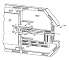
Coupled to the arm portion 28 is a lever 34 that is rotatable about a pivot point 36 between a clamped position and an unclamped position. In FIG. 2 , the lever 34 is in the unclamped position. Counterclockwise rotation of the lever 34 about the pivot point, approximately 180 degrees, moves the lever 34 into the clamped position. At one end of the housing, an electrical cable 38 and an electrical signal conductor 40 enter the housing 20 through an opening 42 in the front of the housing 20. The electrical cable 38 supplies a high voltage, and the electrical signal conductor 40 supplies a low voltage, to the microfluidic cartridge 16, as described herein. Not shown are the microfluidic tubing and a gas line, which also enter the housing 20 through the opening 42, for bringing fluid and gas, respectively, to the microfluidic cartridge 16.
The electrical cable 38 and an electrical conduit 66 couple to one side of the clamping assembly 60. The electrical cable 38 carries a high voltage (e.g., 3000 volts), and the electrical conduit 66 bundles a plurality of low-voltage electrical conductors. Not shown are the microfluidic tubing and gas line that are also coupled to the same side of the clamping assembly 60 as the electrical cable 38 and the electrical conduit 66.
The clamping assembly 60 has a slot 68 for receiving a microfluidic cartridge and a post 70 to which the lever 34 (FIG. 2 ) is attached. When the front cover 50 is closed, the slot 14 in the front cover 50 aligns with the slot 68 of the clamping assembly 60, the adjustment knob 32 of FIG. 2 (not shown in FIG. 3 ) projects through the opening 72 in the front cover 50, and the post 70 projects through another opening, which is obscured by the sidewall of the arm portion 28.
The back wall 86 of the end housing 82 has a pogo pin block 88 and a fluidic block 90. The pogo pin block 88 includes a two-piece bracket 92, joined by fasteners 94, for retaining the electrical conduit 66 (not shown) therebetween. The pogo pin block 88, mostly obscured in FIG. 4 by the two-piece bracket 92, is disposed adjacent to and above the fluidic block 90. This embodiment of fluidic block 90 has three apertures 96 for receiving the ends of tubes that deliver fluid. A spacer block 98 secures the pogo pin block 88 and fluidic block 90 within a slot (shown in FIG. 8 ) in the back wall.
Projecting from a surface of the back wall 86 is an L-shaped retainer 100 having a major surface 102 with three openings 104, 106, 108 therein. The opening 104 is for retaining a gas line (not shown) that is coupled to the clamping assembly 60; the opening 106 is for retaining the high-voltage electrical cable 38 (FIG. 3 ), and the opening 108 is for receiving a fastener that joins the retainer 100 to the back wall 86. Extending from the rear side of the clamping assembly 60 (i.e., the side presented to the MS unit 18 of FIG. 1 ) is an arm 110 used to restrict the extent to which the microfluidic cartridge 16 can be inserted through the slots 68.
The interior side of the pogo pin block 88 has a recessed region 140 with a pogo pin electrical connector 142 projecting inwardly from a surface thereof. In this example, the electrical connector 142 has ten electrically conductive pogo pins 144 for conducting electrical signals. Each pogo pin 144 is an individual cylindrical, spring-loaded electrical conductor for transmitting electrical signals.
The interior side of the fluidic block 90 has the plurality of microfluidic nozzles 130-1, 130-2, 130-3 (generally, 130) of FIG. 6 projecting therefrom. In one embodiment, the nozzles 130 are three in number and arranged in a triangular pattern. The locations of these nozzles 130 are fixed with respect to each other. Fluid delivered by microfluidic tubes to the apertures 96 (FIG. 4 ) on the exterior side of the fluidic block 90 exits through these nozzles 130. Situated below the triangular pattern of nozzles 130, aligned with the nozzle at the apex of the triangle, is the guide pin 128.
As examples of fluidic plumbing, the tip of a microfluidic tube 172 is press fit into fluidic inlet ports 170-1 and 170-3, whereas fluidic inlet port 170-4 is blocked with a plug 174 (i.e., unused), and fluidic inlet port 170-2 is open. The back wall 86′ also includes an alternative embodiment of a pogo pin block 88′ having a single row of electrical connectors 176 (here, e.g., ten in number).
This embodiment of microfluidic cartridge 16 is made by joining two casing sections 200-1, 200-2, for example, by snapping the halves together, or using glue or mechanical fasteners, or any combination thereof. The two casing sections are also referred to herein as the left and right sides of the microfluidic cartridge 16, with the terms left and right being determined by the orientation of the microfluidic cartridge 16 when it is inserted into the clamping assembly 60. It is to be understood that such terms as left, right, top, bottom, front, and rear are for purposes of simplifying the description of the microfluidic cartridge, and not to impose any limitation on the structure of the microfluidic cartridge itself.
The right casing section 200-1 has a grip end 202 and an emitter end 204. A curved region 206 within the grip end 202 provides a finger hold by which a user can grasp the microfluidic cartridge 16 when inserting and removing it from the liquid chromatography module 12.
In the side of the casing section 200-1 is a rectangular-shaped window 208, within which resides a push block 210. The surface of the push block 210 lies flush with the surface of the right casing section 200-1. As described further below, the push block 210 is not rigidly affixed to the right casing section 200-1, and can move slightly in, out, up, down, left, or right; that is, the push block 210 floats within the window 208. In one embodiment, the push block 210 is made of metal.
Disposed below the push block 210 is an opening 212, which extends completely through both casing sections 200-1, 200-2. Hereafter, the opening 212 is referred to as a through-hole 212. At the emitter end 204 is a nook 214 in the top edge of the microfluidic cartridge 16. Within the nook 214, a movable fin 216 projects through the top edge between the casing sections 200-1, 200-2.
Concentrically located behind each nozzle opening 220 is a microscopic fluidic aperture in the side of a microfluidic substrate housed within the microfluidic cartridge. The fluidic conduits of the microfluidic nozzles 130 of the fluidic block 90 have much larger inner diameters than the size of the microscopic apertures in the microfluidic substrate, which facilitates alignment therebetween. In one embodiment, each microscopic fluidic aperture has a 0.003″ square cross section, and each microfluidic nozzle 130 has a 0.013″ orifice (lumen with a circular cross section) that aligns with and circumscribes the microscopic fluidic aperture on the substrate, such as a 0.003″ via (aperture with a square cross section.)
The microfluidic nozzles 130 utilize a polymer-to-ceramic interface, relying only on the compressive stress provided by the clamping assembly 60 (FIG. 6 ) to provide a fluidic seal; that is, the clamping assembly 60 provides a greater pressure at the polymer-to-ceramic interface than the operating fluidic pressure. For example, for an operating fluidic pressure of 5,000 psi—or alternative pressures, such as 15,000 psi—are implemented with a clamping load of 130 pounds across the total surface area of the nozzle-to-substrate interface, producing an effective fluidic seal for the selected operating pressure.
Directly above the apex of the triangularly arranged nozzle openings 220 is a rectangular depression 222 within the left casing section 200-2. The depressed region 222 surrounds a rectangular-shaped window 224 through which an array of electrical contacts 226 is accessed. The electrical contacts 226 are electrically conductive pads for making electrical contact with the pogo pins 144 of the pogo pin block 88 (FIG. 7 ). The array of electrical contacts 226 is part of a flex circuit overlaid upon the microfluidic substrate, as described further below in connection with FIG. 13 .
At the emitter end 204, the left casing section 200-2 has a gas inlet port 225 for receiving a gas nozzle and a high-voltage input port 228 for receiving the tip (pogo-pin) of the high-voltage electrical cable 38 (FIG. 5 ). A plurality of holes 234 hold alignment pins 236 that are used to align the casing sections 200-1, 200-2 when the halves are being joined.
The left casing section 200-2 further includes a rectangular-shaped groove 230 along its bottom edge. The groove 230 has an open end 232 at the emitter end 204, extends laterally therefrom, and terminates at the through-hole 212 situated below the nozzle openings 220. In addition, the groove 230 receives the guide pin 128 (FIG. 7 ) when the microfluidic cartridge 16 is inserted into the slot 68 (FIG. 4 ) of the clamping assembly 60. When the guide pin 128 reaches the through-hole 212, then the microfluidic cartridge 16 is fully installed in the chamber 120 and in position for clamping.
In addition, this embodiment of push block 210 has three raised bosses 260, each with a planar face. The planar faces of the three bosses press simultaneously against the side of the microfluidic substrate when an urging force is applied to the push block 210 from an exterior side of the first casing section 200-1, spreading out the force to avoid a single concentrated point of contact. Each raised boss 260 aligns directly opposite one of fluidic apertures in the microfluidic substrate 250, and thereby applies pressure (when the push block is pushed) directly opposite one of the nozzle openings 220 in the left casing section 200-2, thus avoiding production of shear stresses by, for example, twisting and or bending the microfluidic substrate 250.
Other embodiments can have more, or fewer, than three bosses. In general, the number of bosses corresponds to the number of fluidic apertures (which may include dummy apertures) in the microfluidic substrate 250, so that there is one boss for each fluidic aperture, aligned directly opposite that fluidic aperture. In general, the number of bosses corresponds to the number of fluidic nozzles and dummy nozzles that contact the microfluidic substrate 250, so that all bosses align with a corresponding nozzle. The number and arrangement of bosses and nozzles are optionally selected to control application of undesirable stresses to the microfluidic substrate 250.
The emitter assembly 252 includes an emitter 266, an emitter retainer 241A that positions and/or aligns the emitter 266 with the microfluidic substrate 250, and a sheath-gas component 279. The sheath-gas component 279 receives a sheath gas via a tube 278, which is disposed in the housing sections 200-1, 200-2. The emitter retainer 241A aligns a lumen of the emitter 266 with an outlet port of the microfluidic substrate 250. Preferably, additional component(s) urge the emitter 266 into contact with the microfluidic substrate 250, with sufficient force to provide a greater interfacial pressure than a pressure of an eluent flowing through the outlet port into the lumen of the emitter 266.
Folded over a top edge of the microfluidic substrate 250, a flex-circuit assembly 258 includes the array of electrical contacts 226. As described in FIG. 12 , these electrical contacts 226 are accessible through the window 224 in the left casing section 200-2. Further, the shutter 254 has holes 262 that align with the nozzle openings 220 in the side of the left casing section 200-2 so that the microscopic fluidic apertures in the surface of the microfluidic substrate 250 are exposed. In addition, the shutter 254 has the fin 216 (FIG. 11 ) and an emitter tube 264 that partially envelopes the electrospray emitter 266.
The substrate 250 is optionally formed in the following manner. Five green-sheet layers, for multiple substrates 250, are pressed together, after desired patterning. Vias for fluidic apertures are laser etched in one or both sides of the pressed sandwich. Edge portions are defined by laser etching. After firing, individual substrates 250 are snapped apart. Edges, or portions of edges, are optionally polished.
On the surface of the microfluidic substrate 250 is the flex-circuit assembly 258, comprised of a control circuitry portion 257 and a heater portion (hereafter, heater 270). The flex-circuit assembly 258 folds over a top edge of the microfluidic substrate 250 and covers a portion of the opposite side of the microfluidic substrate 250. An integrated circuit (IC) device 272 is mounted on the control circuitry portion of the flex-circuit assembly 258. In one embodiment, the IC device 272 is a memory device (e.g., EPROM) for storing program code and data. The heater 270 covers a separation column within the microfluidic substrate 250. Mounted to the heater 270 is a temperature sensor 274.
The flex-circuit assembly 258 is constructed of multiple stacked layers (e.g., three, four, or five). The polymer substrate of each layer holds different interconnectivity or circuitry. One of the layers contains resistive traces of the heater 270. Electrical contacts at the two ends of the resistive traces connect to two pads 259 on the control circuitry portion 257. Another layer of the flex-circuit assembly 258 has vias that electrically contact the ends of the resistive traces, another layer has contacts to connect electrically to electrical components 272, 274, and still another layer has the pogo-pin contact pads 226 (FIG. 13 ). Through the flex-circuit assembly 258, each of the electrical components 272, 274 and resistive traces are electrically coupled to the contact pads 226. The gas inlet port 225 opens into a well 276 that channels injected gas into the gas tube 278 that delivers the gas to the emitter end 204.
The interior side of the right casing section 200-1 includes a ridge 292 of casing material that runs from the emitter end 204 and terminates at the through-hole 212. When the casing sections 200-1, 200-2 are joined, the ridge 292 runs directly behind the groove 230 (FIG. 12 ) on the exterior side of the left casing section 200-2. The ridge 292 provides structural support to the microfluidic cartridge 16. In addition, by being directly opposite the groove 230, the ridge 292 resists bending of the cartridge 16 by the guide pin 128 (FIG. 7 ) should a user prematurely attempt to clamp the microfluidic cartridge 16 before the microfluidic cartridge 16 has fully reached the proper position. In addition, no portion of the microfluidic substrate 250 lies directly behind the groove 230, as a precautionary measure to avoid having the guide pin 128 bend the microfluidic substrate 250 in the event of a premature clamping attempt.
The interior side of the right casing section 200-1 provides the other half of the gas well 276, the walls of which align with and abut those defining the well 276 on the left casing section 200-2. To enhance a tight seal that constrains gas to within the gas well 276, a fastener or pin 296 (FIG. 14 ) tightens the connection between the casing sections at an opening 298 adjacent the well 276.
The microfluidic substrate 250 also has a high-voltage input port 290 (FIG. 16 ) and a pair of alignment openings 310-1, 310-2 (generally, 310) that each receives a peg that projects from an interior side of the left casing section 200-2. The alignment openings 310 help position the microfluidic substrate 250 within the microfluidic cartridge 16. The size of the alignment openings 310, with respect to the size of the pegs, allows the microfluidic substrate 250 some play within the microfluidic cartridge 16.
Rather than a single microfluidic substrate 250, the microfluidic cartridge 16 can house a plurality of interconnected microfluidic substrates. FIG. 18 shows one embodiment with a plurality of the microfluidic substrates 250-1, 250-2 joined by fittings. The microfluidic substrates 250-1, 250-2 include a trap tile 250-1 coupled to a column tile 250-2. The trap tile 250-1 has a fluid-conducting channel 300-1 and the column tile 250-2 has a fluid conducting channel 300-2.
This embodiment of the trap tile 250-1 has three fluidic apertures (an open spot 318 in the tile 250-1 represents a possible embodiment having a fourth fluidic aperture). Coupled about each fluidic aperture is a fitting 320-1, 320-2, 320-3 (generally 320). The fittings 320 serve to self-align the tips of the nozzles (e.g., nozzles 130 or 184 of FIG. 7 or FIG. 10 , respectively) on the fluidics block 90 when the microfluidic cartridge 16 is installed in the chamber, as described in more detail below. These fittings 320 can be made of metal, plastic, ceramic, or any combination of these materials. To couple the fittings 320 to the substrate 250-1, they can be glued, fastened, fused, brazed, or a combination thereof.
Preferably, the couplers 322 are formed of a deformable matter, for example, similar to or the same as the material of the nozzles 130; mechanical pressure alone can then provide a fluid-tight seal between the trap tile 250-1 and the couplers 322. Alignment-assisting features, such as the couplers 322, are optionally included in the embodiment illustrated in FIG. 17 and in other embodiments.
In FIG. 20 , the load spring 356 and return spring 358 are undamped; the lever 34 (FIG. 6 ), which is coupled to the cam 350, is in the open, unclamped position. In addition, springs 360-1, 360-2 (generally, 360) between the back wall 86 and the carriage 122 are likewise undamped. Projecting into the empty chamber 120, from the back wall of the end housing 82, are a pogo pin electrical connector 144, gas nozzles 130-1, 130-2 (a third nozzle being obscured), and the guide pin 128.
In FIG. 21 , the microfluidic cartridge 16 is the chamber 120, with the emitter end of the cartridge entering the chamber 120 first. As the microfluidic cartridge 16 enters the chamber 120, the guide pin 128 slides along the groove 230 in the left casing section 200-2. When insertion of the microfluidic cartridge 16 into the chamber 120 reaches its limit, the plunger 126 abuts the push block 210 on the right side of the microfluidic cartridge 16, and the guide pin 128 reaches the through-hole 212 (FIG. 12 ) at the end of the groove 230. If the guide pin 128 is not aligned with this opening, the microfluidic cartridge 16 cannot be clamped. In one embodiment, the engagement of the arm 110 (FIG. 5 ) with the nook (FIG. 11 ) in the upper edge of the microfluidic cartridge 16 determines how far the microfluidic cartridge 16 can enter the chamber. In addition, the springs 124-1, 124-2 abut the right side of the microfluidic cartridge 16. As in FIG. 20 , in FIG. 21 the load spring 356, the return spring 358, and the springs 360 are undamped because the lever 34 is in the open position.
In FIG. 22 , the lever 34 is closed, and the cam 350 causes the load spring 356 and return spring 358 to compress and urge the plunger 126 against the push block 210. The spaced-apart bosses 260 (FIG. 13 ) on the other side of the push block 210 distributes this force against the microfluidic substrate 250. The force against the push block 210 moves the carriage 122 and the microfluidic cartridge 16, together, towards the back wall 86 of the end housing 82. In addition, the spring 124-1 operates to push the microfluidic cartridge 16 downwards and toward the back wall 86, while springs 360-1, 360-2 (FIG. 21 ) compress, resisting the leftwards motion.
As a result of moving the carriage with the cartridge 16, the guide pin 128 penetrates the through-hole 212 in the microfluidic cartridge 16. The nozzles 130 that project inward from the back wall 86 enter the respective nozzle openings 220 (FIG. 12 ) in the left casing section of the microfluidic cartridge 16, and press against the surface of the microfluidic substrate 250. The urging force is sufficient to produce a sealed fluidic pathway between the each nozzle and the fluidic aperture. The clamping also causes the pogo pins 144 to enter the window 224 on the left casing section and make electrical connections with the array of electrical contacts 226.
In addition to establishing the fluidic interface between the nozzles of the fluidic block and the microfluidic substrate, and the electrical interface between the pogo pins 144 and the array of electrical contacts 226, this clamping action also establishes (1) the electrical interface between the high-voltage pogo pin and the microfluidic substrate and (2) the fluidic interface between the gas nozzle and the microfluidic cartridge 16. FIG. 23 shows the high-voltage electrical cable 38 with a pogo pin 380 entering the left casing section of the microfluidic cartridge 16, and a gas nozzle tip 382 entering the gas inlet port of the left casing section.
Some preferred embodiments entail apparatus of reduced cost and size relative to existing apparatus, such as existing analytical equipment based on LC-MS. Miniaturization provides many potential benefits in addition to size reduction, for example: improving reliability; reducing the quantity and cost of reagents, and the cost of used-reagent disposal; and improve performance reducing dispersion in LC-related components. While preferred embodiments, described herein, relate to liquid chromatography, one of skill will recognize that the invention may be applied to other separation techniques.
In addition to the emitter 266, the spray unit of the embodiment of FIG. 24 includes a retainer 240 (also referred to herein as an alignment unit), a force-applying unit (in this example, a spring 241), and a force-receiving component (in this example, a fitting 242 attached to the emitter 266). The retainer 240 receives and aligns the emitter 266 with the microfluidic substrate 250. The retainer 240 is preferably fixedly attached to the microfluidic substrate 250. The spring 241 is enclosed within the retainer 240; the retainer 240 urges the spring 241 against the fitting 242, which in turn transfers the spring force to the emitter 266, to urge the emitter 266 into contact with the microfluidic substrate 250. The fitting 242 is optionally a crimped sleeve, located, for example, approximately ⅛″ from the inlet end of the lumen L.
In this example embodiment, the lumen L has a circular cross section and the outlet orifice E is approximately rectangular. The diameter of the lumen L is smaller than a diagonal of the orifice. The interface a desirably provides a small amount of, or no, dead volume, and reduces dispersion effects relative to many existing LC-to-spray interfaces. These dimensions are preferably small for some applications of interest, imposing some difficulty on proper alignment to dispose the inlet of the lumen L in correct relation to the outlet orifice E of the substrate 250 and to achieve a good mechanical interface between the emitter 266 and the substrate 250. Emitter tubes 266 are optionally selected for the position tolerance of the lumen L relative to the central axis position of the tubes 266.
In one embodiment, for example, which is suitable for small sample volumes, the emitter 266 has an outer diameter of 0.030 inch, an inner diameter of 0.001 inch, and the orifice outlet has dimensions of 0.0039 inch×0.0036 inch. FIG. 25C is a side view, illustrating the use of a retainer 345 to position the emitter 266. The retainer 345, in this example, has an inner diameter of 0.032 inch. Thus, when the emitter 266 is positioned within the retainer 345, there is approximately 0.002 inch of lateral variability in positioning of the lumen L relative to the outlet orifice E due to the lateral tolerance of the emitter 266 within the retainer 345. The retainer 345, position of the retainer relative to the outlet orifice E, size of the outlet orifice E, emitter 266, size of the lumen L, and position of the lumen L within the emitter 266 cooperate to achieve alignment of the inlet of the lumen L fully within the boundaries of the outlet orifice E. Generally, the positioning of the retainer 345 relative to the microfluidic substrate 250 must have sufficient accuracy for the retainer 345 to play its role in the alignment process. One method of assembling the microfluidic substrate 250 and retainer 345 combination, to achieve such sufficient accuracy, is described below with reference to FIGS. 27A and 27B .
In this example, the spring 241 applies a force of, for example, approximately 7 lbs. In some LC-MS embodiments, the sealing pressure required at an outlet of a microfluidic substrate is less than at an inlet because of a lower pressure of a liquid in the vicinity of the outlet in comparison to the pressure at the inlet. Preferably, the force applied is sufficient to provide a pressure at the interface that is greater than a pressure of an eluent passing through the interface.
In one embodiment of a method of assembly a substrate and retainer, the retainer 345 is first touched against the microfluidic substrate and then backed off slightly (in the y direction), just enough to permit movement of the retainer without rubbing against the microfluidic substrate, for example, less than 0.010″. During x-z adjustment of the position of the retainer 345, the orifice is observed within the circle of the adjacent end of the passageway. After the retainer 345 is in a correct position relative to the orifice to permit the retainer 345 to properly align an emitter's lumen relative to the orifice, the retainer 345 is attached to the microfluidic substrate. A permanent attachment is optional.
Glue, for example, accommodates space (acting as a spacer) between a retainer and a substrate that is intentionally introduced to accommodate alignment adjustment. As noted, the retainer and/or substrate optionally provide spacing between the retainer surfaces and the orifice so that glue does not wick into the vicinity of the orifice.
For example, a drop of heated glue is placed at the retainer 345 and substrate 250; capillary action draws the glue into a gap between the retainer 345 and substrate 250. Capillary action is preferably exploited so that glue does not wick past the preferably narrow gap between the retainer 345 and substrate 250.
Some alternative embodiments automate assembly of substrates and retainers, for example, using machine vision. Some alternative embodiments utilize substrates and retainers have mechanical tolerances that do not require optical alignment. For example, a substrate optionally includes a slot that receives a retainer, without need for human or machine visual alignment. Optionally, the portion of the edge of the substrate that contacts the emitter 266 and/or the contact end of the emitter 266 are smoothed, for example, mechanically polished, to provide an improved contact interface.
Any one of many suitable means is optionally used to attach an emitter to a retainer. For example, a retainer/housing is optionally placed over the emitter and attached to the guide (i.e., retainer 345). To apply a mechanical force to the emitter to form the seal with the microfluidic substrate, in one example, a metal ring is crimped to the emitter, a spring is placed in a retainer/housing, and the housing is then attached to the guide (i.e., retainer 345).
Returning to FIG. 26 , the retainer 345 has a cutout that permits observation of the region of the substrate's orifice during and after assembly. In this example embodiment, the substrate 250 has a recessed edge portion, for mating with the retainer 345. A recessed edge is optionally used, for example, to produce a desirably smooth edge in the vicinity of the orifice and/or to protect the orifice portion of the edge. Optionally, glue is applied, to join the retainer 345 to the substrate 250, at location(s) where the edge is not recessed, further protecting the orifice from the glue. In the illustrated embodiment, the retainer 345 does not contact any of the perimeter of the edge face of the substrate 250 that bounds the recessed portion.
An edge (also referred to herein as a side) of a microfluidic substrate is formed in any of several suitable manners, for example, via etching, cleaving, and/or polishing. For example, in one embodiment, an edge is formed by cleaving after sintering of a substrate material; in another embodiment, by patterning of a substrate material prior to sintering. The edge is optionally further shaped and/or smooth before and/or after firing.
Referring to FIGS. 28A and 28B , some embodiments provide a microfluidic cartridge having a replaceable and/or detachable portion holding a spray unit. The spray unit, in these embodiments, is optionally similar to those described above.
The primary cartridge portion 316 has left and right housing portions 450-1, 450-2, and holds a retainer 345 (depicted as optionally similar to the retainer 345 described above.) The detachable cartridge portion 317 has right and left housing portions 460-1, 460-2, which define a spray-tip protection feature 311. The right and left housing portions 460-1, 460-2 hold the emitter 266, spring 341 and fitting 342, and define a gas passageway 376 for delivering a gas to surround the spray tip. The left housing portion 460-2 defines a spring-retaining feature 343 that secures the spring 341 and applies a force to the spring 341 when the detachable portion 317 is attached to the primary cartridge portion 316. The left and right housing portions 460-1, 460-2 also define latch features 312 for connecting the detachable cartridge portion 317 to the primary cartridge portion 316. Alternative embodiments optionally utilize any suitable attaching features, including known features such as screws, clips, and magnets.
One of skill will note that the phrase “spray unit”, as used herein, is for descriptive convenience, and is not intended to limit a spray unit to any specific set of components or to limit the location of such components. For example, a portion of the spray unit of FIGS. 28A and 28B (i.e., the retainer 345) resides in the primary cartridge portion 316 while other portions of the spray unit reside in the detachable cartridge portion 317. Alternatively, for the purposes of FIGS. 28A and 28B , a spray unit could be defined as including only parts associated with the detachable cartridge portion 317.
Some embodiments entail emitter assemblies that include a deformable cartridge portion that contacts a microfluidic substrate at a proximal end of the emitter assembly, and a conductive emitter portion at a distal end of the emitter assembly. Some of these embodiments provide both a leak-proof fluidic seal to the microfluidic substrate and a well controlled electrospray output of an eluent received from the microfluidic substrate. Some embodiments of emitter assemblies are optionally used in place of the above-described emitter 266 and related components.
When the detachable cartridge portion 552-2 attaches to the primary cartridge portion 552-1, the metal plate 570 within in the detachable cartridge portion 552-2 presses against the distal end of the emitter loading spring 566. The spring 566 presses against a spring retainer 582. This spring retainer 582, which is coupled to the proximal end of the emitter assembly 560, urges the proximal end of the tubing assembly 564 against the microfluidic substrate 250 with sufficient force to provide a fluidic seal for pressures expected at the eluent outlet port of the microfluidic substrate 250. In FIG. 33 , the spring 566 is shown uncompressed (and obscures the spring retainer 582), to show, by comparison with the compressed spring 566 in FIG. 34 , the degree to which the spring 566 compresses when confined by the spring retainer 345.
In this particular embodiment, the tubing assembly 564 includes an outer steel tube 600 and multiple polymer intermediate tubes 602-1, 602-2, and 602-3 (generally, 602). The polymer intermediate tube 602-1 is at the proximal end of the emitter assembly 560 and is formed, for example, of PEEK™ polymer, as described above for materials with reference to the tubing embodiments. The end of the proximal intermediate tube 602-1 preferably extends beyond the outer steel tube 600 (the outer steel tube 600 ending approximately at the proximal opening in the compartment 568). In addition, the end of the proximal intermediate tube 602-1 preferably extends beyond the inner metal emitter tube 562 by a length sufficient to provide a fluid-tight fluidic seal when in mechanical contact with the microfluidic substrate 250. The length 604 of the extension is, for example, in a range of 0.001 inch to 0.005 inch. This extension length enables this end of the proximal intermediate tube 602-1 to deform sufficiently against the rigid edge of the microfluidic substrate 250 and produce the fluid-tight seal before the microfluidic substrate 250 can come into contact with the rigid, inner, metal emitter tube 562.
The second polymer intermediate tube 602-2 abuts the proximal intermediate tube 602-1, and is, in one embodiment, a carbon-filled PEEK™ polymer tube. This intermediate tube 602-2 provides an electrically conductive pathway between the outer steel tube 600 and the inner steel emitter tube 562. The third polymer intermediate tube 602-3, at the distal end of the emitter assembly 560, is separated from the second intermediate tube 602-2 by a gap 606. The outer steel tube 600 has apertures 608 in the region of the gap 606 to enable nebulizing gas to enter therein.
The polymer tubes 602 of the tubing assembly 564 are optionally mechanically fixed to one another by crimping of the outer steel tube 600. One or more crimps can be optionally formed along the proximal end of the tubing assembly 564. Alternatively, a seal involving uniform mechanical deformation of one or more portions of the outer steel tube 600 can be employed.
At the distal end of the emitter assembly 560 is the electrically conductive metallic block 576. The metallic block 576 has a bore 612 extending therethrough. The bore 612 is sized to closely receive the tubing assembly 564. The metallic block 576 has an outlet (distal) portion 630 through which nebulizing gas flows and through which the distal end of the inner metal emitter tube 562 extends.
At one end of the bore 612 of the metallic block 576 is a gland 614, and disposed within the gland 614 is an o-ring 616 through which the tubing assembly 564 and the inner metal emitter tube 562 pass. The o-ring 616 seals the bore 612, preventing any nebulizing gas from escaping the bore 612 in the proximal direction. The metallic block 576 also has an input port 618 that intersects the bore 612 at its distal end. The nebulizing gas tube 580 (FIG. 33 ) delivers nebulizing gas to the bore 612 of the metallic block 576.
At the distal end of the emitter assembly 560, a gap 620 separates the outer steel tube 600 from the bore 612 of the metallic block 576, another gap 622 separates the third polymer intermediate tube 602-3 from the inner steel emitter tube 562, and still another gap 623 separates the third polymer intermediate tube 602-3 from the outer steel tube 600. The gap 620 narrows at the distal end of the third polymer intermediate tube 602-3. Some nebulizing gas exits the bore 612 in the distal direction through the gap 620 between the outer steel tube 600 and the bore 612. Nebulizing gas that enters the gap 620 through the apertures 608 also exits the bore 612 in the distal direction through the gap 622 between the third polymer intermediate tube 602-3 and the inner steel emitter tube 562 and the gap 623 between the third polymer intermediate tube 602-3 and the outer steel tube 600. In one embodiment, a gap dimension for the narrowed portion of the gap 620 is in a range of 0.001 to 0.003 inch, a gap dimension of the gap 622 between the inner steel emitter tube 562 and the third polymer intermediate tube 602-3 is, for example, in a range of 0.001 to 0.003 inch, and a gap dimension of the gap 623 between the third polymer tube 602-3 and the outer steel tube 600 is, for example, in a range of 0.0005 to 0.0015 inch.
A high voltage (HV) strap 624 delivers high voltage, for the production of an electrospray, from a high voltage input 626 to the metal plate 570. A high voltage spring 628 coupled between this metal plate 570 and the metallic block 576 conducts the high voltage to the metallic block 576. In a compressed state, one end of the high voltage spring 628 extends into a pocket (not shown) of the metallic block 576, and the opposite end presses against the metal plate 570. The conduction of high voltage continues to the outer steel tube 600, the carbon-filled intermediate tube 602-2, and to the inner metal emitter tube 562. The dimensions of the orifice 630 of the metallic block 576 and the extension distance 632 of the emitter tube 562 are selected to provide desired performance of the electrospray. For example, the tip extension distance 632 (FIG. 35B ) is, for example, in a range of 0.05 to 0.09 inch. The length 634 of the outlet portion of the metallic block 576 is, for example, in a range of 0.03 to 0.07 inch.
The emitter loading spring 566 provides a force that opposes the latching of the detachable cartridge portion 552-2 to the primary cartridge portion 552-1. This force urges the deformable end portion of the emitter assembly 560 against the microfluidic substrate 250. In addition, in one embodiment, the tip 572 of the emitter tube 562 may project from the extension 630 of the microfluidic block 576 in response to the detachable cartridge portion 552-2 being attached to the primary cartridge portion 552-1, and retract into the extension 630 of the microfluidic block 576 in response to the detachable cartridge portion 552-2 being detached from the primary cartridge portion 552-1.
While the invention has been shown and described with reference to specific preferred embodiments, it should be understood by those skilled in the art that various changes in form and detail may be made therein without departing from the scope of the invention. For example, an emitter tube assembly optionally includes more or few sections and/or layers of tubes, which are optionally formed of suitable alternative polymeric and/or alternative metallic and/or other conducting materials.
Claims (8)
1. An apparatus for chemical separations comprising:
a microfluidic substrate having an outlet aperture for outputting an eluent of a sample;
an emitter assembly having a deformable end portion, an inlet near the deformable end portion to receive the sample eluent from the microfluidic substrate, and an electrically conductive emitter tube to emit a spray of the sample eluent, and a tubing assembly disposed around and coupled to the emitter tube, the tubing assembly comprising a first tube section having the deformable end portion, a second tube section abutting the first tube section end-to-end, and a third tube section spatially separated from the second tube section by a gap;
an electrically conductive block disposed around a distal end of the tubing assembly and the emitter tube, the electrically conductive block having a bore through which the tubing assembly and emitter tube extend, with a tip of the emitter tube extending beyond a distal end of the electrically conductive block; and
a force-applying unit applying a force to the emitter assembly that urges the deformable end portion into contact with the microfluidic substrate, the deformable end portion being more elastic than the microfluidic substrate so that the contact between the microfluidic substrate and the deformable end portion produces a substantially fluid-tight seal between the outlet aperture of the microfluidic substrate and the inlet of the emitter assembly.
2. The apparatus of claim 1 , wherein the force-applying unit includes:
a spring retainer fixedly coupled to the tubing assembly; and
a spring coiled around the tubing assembly and abutting the spring retainer to apply the force to the spring retainer that urges the deformable end portion against the microfluidic substrate.
3. The apparatus of claim 1 , wherein the second tube section of the tubing assembly is comprised of an electrically conductive material.
4. The apparatus of claim 1 , wherein the emitter assembly further comprises an electrically conductive outer tube disposed around the tubing assembly.
5. The apparatus of claim 1 , wherein the electrically conductive block has an aperture, and further comprising a nebulizing gas tube joined to the electrically conductive block at the aperture.
6. The apparatus of claim 5 , wherein the tubing assembly further comprises an electrically conductive outer tube around the tubing assembly, the electrically conductive outer tube having an orifice to allow nebulizing gas to enter gaps between the tubing assembly and the emitter and between the third tube of the tubing assembly and the electrically conductive outer tube.
7. The apparatus of claim 6 , further comprising an electrical conductor in electrically conductive communication with the electrically conductive block and the electrically conductive outer tube of the tubing assembly, the electrical conductor conducting high voltage from a high voltage source to the electrically conductive block and to the electrically conductive outer tube to induce an electrospray emission comprised of the nebulizing gas from the emitter tube tip.
8. The apparatus of claim 1 , further comprising:
a primary microfluidic cartridge portion that houses the microfluidic substrate; and
a detachable microfluidic cartridge portion within which the emitter assembly is movably disposed, wherein a tip of the emitter tube projects from the detachable microfluidic cartridge portion in response to the detachable microfluidic cartridge portion being attached to the primary microfluidic cartridge portion, and retracts into the detachable microfluidic cartridge portion in response to the detachable microfluidic cartridge portion being detached from the primary microfluidic cartridge portion.
Priority Applications (1)
| Application Number | Priority Date | Filing Date | Title |
|---|---|---|---|
| US14/131,162 US9518963B2 (en) | 2011-08-26 | 2012-08-23 | Electrospray emitter assemblies for microfluidic chromatography apparatus |
Applications Claiming Priority (7)
| Application Number | Priority Date | Filing Date | Title |
|---|---|---|---|
| US201161527638P | 2011-08-26 | 2011-08-26 | |
| US201161527648P | 2011-08-26 | 2011-08-26 | |
| US201161527639P | 2011-08-26 | 2011-08-26 | |
| US201161527747P | 2011-08-26 | 2011-08-26 | |
| US201261621852P | 2012-04-09 | 2012-04-09 | |
| US14/131,162 US9518963B2 (en) | 2011-08-26 | 2012-08-23 | Electrospray emitter assemblies for microfluidic chromatography apparatus |
| PCT/US2012/052032 WO2013032848A1 (en) | 2011-08-26 | 2012-08-23 | Electrospray emitter assemblies for microfluidic chromatography apparatus |
Publications (2)
| Publication Number | Publication Date |
|---|---|
| US20140217196A1 US20140217196A1 (en) | 2014-08-07 |
| US9518963B2 true US9518963B2 (en) | 2016-12-13 |
Family
ID=47756739
Family Applications (6)
| Application Number | Title | Priority Date | Filing Date |
|---|---|---|---|
| US14/131,162 Active 2033-05-28 US9518963B2 (en) | 2011-08-26 | 2012-08-23 | Electrospray emitter assemblies for microfluidic chromatography apparatus |
| US14/233,212 Expired - Fee Related US10451594B2 (en) | 2011-08-26 | 2012-08-23 | Liquid chromatography conduit assemblies having high pressure seals |
| US14/238,278 Active 2033-07-16 US9983178B2 (en) | 2011-08-26 | 2012-08-23 | Chromatography column assembly |
| US14/233,033 Expired - Fee Related US9188571B2 (en) | 2011-08-26 | 2012-08-23 | Chromatography apparatus having diffusion bonded coupler |
| US14/232,711 Active 2035-06-26 US10022736B2 (en) | 2011-08-26 | 2012-08-23 | Reusable fitting for attaching a conduit to a port |
| US15/990,097 Active 2032-11-28 US10802002B2 (en) | 2011-08-26 | 2018-05-25 | Chromatography column assembly |
Family Applications After (5)
| Application Number | Title | Priority Date | Filing Date |
|---|---|---|---|
| US14/233,212 Expired - Fee Related US10451594B2 (en) | 2011-08-26 | 2012-08-23 | Liquid chromatography conduit assemblies having high pressure seals |
| US14/238,278 Active 2033-07-16 US9983178B2 (en) | 2011-08-26 | 2012-08-23 | Chromatography column assembly |
| US14/233,033 Expired - Fee Related US9188571B2 (en) | 2011-08-26 | 2012-08-23 | Chromatography apparatus having diffusion bonded coupler |
| US14/232,711 Active 2035-06-26 US10022736B2 (en) | 2011-08-26 | 2012-08-23 | Reusable fitting for attaching a conduit to a port |
| US15/990,097 Active 2032-11-28 US10802002B2 (en) | 2011-08-26 | 2018-05-25 | Chromatography column assembly |
Country Status (6)
| Country | Link |
|---|---|
| US (6) | US9518963B2 (en) |
| EP (5) | EP2747896B1 (en) |
| JP (2) | JP6021917B2 (en) |
| CN (1) | CN103748396B (en) |
| HK (1) | HK1192772A1 (en) |
| WO (5) | WO2013032834A2 (en) |
Cited By (2)
| Publication number | Priority date | Publication date | Assignee | Title |
|---|---|---|---|---|
| US20170003294A1 (en) * | 2014-01-23 | 2017-01-05 | Newomics Inc. | Methods and systems for diagnosing diseases |
| US10627395B2 (en) | 2015-05-13 | 2020-04-21 | Newomics Inc. | Methods and systems for biomonitoring |
Families Citing this family (26)
| Publication number | Priority date | Publication date | Assignee | Title |
|---|---|---|---|---|
| GB2482175B (en) * | 2010-07-23 | 2016-01-13 | Agilent Technologies Inc | Fitting element with bio-compatible sealing |
| WO2012148699A1 (en) * | 2011-04-25 | 2012-11-01 | Waters Technologies Corporation | Cartridge with multiple electrospray emitters |
| JP6021917B2 (en) | 2011-08-26 | 2016-11-09 | ウオーターズ・テクノロジーズ・コーポレイシヨン | Reusable fitting for attaching a conduit to a port |
| GB2499198A (en) * | 2012-02-07 | 2013-08-14 | Agilent Technologies Inc | Fitting with microprotrusions for coupling capillary to chromatography column |
| WO2014158340A1 (en) | 2013-03-12 | 2014-10-02 | Waters Technologies Corporation | Matching thermally modulated variable restrictors to chromatography separation columns |
| US9201049B2 (en) * | 2013-03-13 | 2015-12-01 | Idex Health & Science Llc | Connector with structural reinforcement and biocompatible fluid passageway |
| US9638676B2 (en) * | 2013-10-18 | 2017-05-02 | Agilent Technologies, Inc. | GC column connection with a planar connection to mating devices |
| WO2015086915A1 (en) * | 2013-12-12 | 2015-06-18 | Societe Technique Pour L'energie Atomique | Method for welding an assembly including a plurality of plates, by means of diffusion and subsequent hot isostatic compression |
| EP3226993B1 (en) * | 2014-12-05 | 2024-01-24 | Advanced Electrophoresis Solutions Ltd | Apparatus and method for separating molecules |
| CH712103A2 (en) * | 2016-02-09 | 2017-08-15 | Döbelin Werner | Fused Silica Kapillarverschraubung. |
| EP3258260B1 (en) * | 2016-06-16 | 2020-01-15 | Lake Region Manufacturing, Inc. | Composite column for use in high pressure liquid chromatography |
| CN109417017B (en) | 2016-07-13 | 2021-11-09 | 赛默海普赛尔基斯通有限公司 | Replaceable transmitter assembly for interfacing a separation column to a mass spectrometer |
| WO2018067304A1 (en) * | 2016-10-05 | 2018-04-12 | Waters Technologies Corporation | Fluidic fitting with integral face seal |
| US10386344B2 (en) | 2017-06-12 | 2019-08-20 | Waters Technologies Corporation | Strain induced face seal |
| US11448624B2 (en) * | 2017-09-14 | 2022-09-20 | Shimadzu Corporation | Ionization probe connection jig, liquid chromatograph, and liquid chromatograph mass spectrometer |
| DE102017129674A1 (en) * | 2017-12-12 | 2019-06-13 | Dionex Softron Gmbh | Plug units, in particular for HPLC, connection system and corresponding use |
| US10422777B1 (en) * | 2017-12-29 | 2019-09-24 | Bio-Rad Laboratories, Inc. | Clamp for chromatography columns |
| WO2019144199A1 (en) * | 2018-01-29 | 2019-08-01 | Ion Opticks Research Pty Ltd | Capillary fitting |
| EP3759479A4 (en) * | 2018-02-26 | 2022-03-09 | Brigham Young University | Integrated column and detector in a module for liquid chromatography |
| WO2019167025A1 (en) * | 2018-03-01 | 2019-09-06 | Dh Technologies Development Pte. Ltd. | Integrated electrospray emitter and methods for making same |
| US11085904B2 (en) * | 2018-09-28 | 2021-08-10 | Idex Health And Science Llc | Column having a compression-limited assembly |
| CN110076547B (en) * | 2019-05-24 | 2024-01-12 | 福建省闽旋科技股份有限公司 | Quick assembly equipment for plane sealing rotary joint with built-in spring |
| EP4014036A1 (en) * | 2019-08-14 | 2022-06-22 | Waters Technologies Corporation | Fitting for fluidic coupling in a chromatography system |
| GB202014233D0 (en) * | 2020-01-24 | 2020-10-28 | Waters Technologies Corp | Sprayer assembly |
| WO2022094016A1 (en) * | 2020-10-28 | 2022-05-05 | Waters Technologies Corporation | Chromatography column positioning assemblies |
| JP2022085229A (en) * | 2020-11-27 | 2022-06-08 | 株式会社島津製作所 | Structure of flow cell assembly for chromatography detectors, and capillary manufacturing method |
Citations (15)
| Publication number | Priority date | Publication date | Assignee | Title |
|---|---|---|---|---|
| US6090278A (en) | 1998-08-20 | 2000-07-18 | Dyax Corporation | Apparatus and method for sealing a plurality of chromatography columns |
| WO2002030486A2 (en) | 2000-10-13 | 2002-04-18 | Fluidigm Corporation | Microfluidic device based sample injection system for analytical devices |
| US20020100714A1 (en) | 2001-01-31 | 2002-08-01 | Sau Lan Tang Staats | Microfluidic devices |
| US6444461B1 (en) | 1997-04-04 | 2002-09-03 | Caliper Technologies Corp. | Microfluidic devices and methods for separation |
| US20030087454A1 (en) | 2001-10-26 | 2003-05-08 | Schultz Gary A | Method and device for chemical analysis |
| US20030141392A1 (en) | 2000-06-08 | 2003-07-31 | Steffan Nilsson | Electrospray emitter |
| US6621076B1 (en) | 2002-04-30 | 2003-09-16 | Agilent Technologies, Inc. | Flexible assembly for transporting sample fluids into a mass spectrometer |
| US6800849B2 (en) | 2001-12-19 | 2004-10-05 | Sau Lan Tang Staats | Microfluidic array devices and methods of manufacture and uses thereof |
| US6864480B2 (en) | 2001-12-19 | 2005-03-08 | Sau Lan Tang Staats | Interface members and holders for microfluidic array devices |
| JP2005197141A (en) | 2004-01-09 | 2005-07-21 | Shimadzu Corp | Mass spectroscopy system |
| US20050230498A1 (en) | 2004-04-08 | 2005-10-20 | Waldemar Ruediger | Nano-electrospray nebulizer |
| US20080038152A1 (en) | 2006-08-12 | 2008-02-14 | Van Pelt Colleen K | Nanoliter flow rate separation and electrospray device with plug and play high pressure connections and multi-sensor diagnostic monitoring system |
| WO2009063776A1 (en) | 2007-11-02 | 2009-05-22 | Humanix Co., Ltd. | Method of capturing cell fluid and analyzing components thereof while observing cell and system for capturing and analyzing cell fluid |
| WO2010102194A1 (en) | 2009-03-06 | 2010-09-10 | Waters Technologies Corporation | Electrospray interface to a microfluidic substrate |
| US20110198842A1 (en) | 2008-05-30 | 2011-08-18 | Waters Technologies Corporation | Device And Method For Connecting Fluid Conduits |
Family Cites Families (63)
| Publication number | Priority date | Publication date | Assignee | Title |
|---|---|---|---|---|
| JPS5433135Y2 (en) * | 1973-06-28 | 1979-10-13 | ||
| US4083702A (en) * | 1976-07-19 | 1978-04-11 | The Perkin-Elmer Corporation | Chromatographic column fittings |
| US4116836A (en) | 1977-03-01 | 1978-09-26 | Henry Allen | Chromatographic column |
| US4357822A (en) * | 1980-09-29 | 1982-11-09 | Dana Corporation | Crimping collet |
| US4400967A (en) * | 1981-08-31 | 1983-08-30 | Owens Carl H | Crimping collet |
| JPS59193351A (en) * | 1983-04-18 | 1984-11-01 | Tokyo Rika Kikai Kk | Connecting device of channel of liquid chromatograph |
| JPH01118361U (en) * | 1988-01-29 | 1989-08-10 | ||
| JPH02141793U (en) * | 1989-04-28 | 1990-11-29 | ||
| US5044190A (en) | 1990-09-04 | 1991-09-03 | Dana Corporation | Base for rotatably supporting a collet crimping machine |
| US5163722A (en) * | 1991-07-26 | 1992-11-17 | Ruska Laboratories, Inc. | Connection apparatus with ferrule forming structure |
| US5601785A (en) * | 1991-12-23 | 1997-02-11 | Microsensor Technology, Inc. | Connector for detachable column cartridge for gas chromatograph |
| US5316262A (en) | 1992-01-31 | 1994-05-31 | Suprex Corporation | Fluid restrictor apparatus and method for making the same |
| US5766460A (en) * | 1992-11-02 | 1998-06-16 | Pharmacia Biotech Ab | Liquid chromatographic system |
| US5234235A (en) * | 1992-11-30 | 1993-08-10 | Ruska Laboratories, Inc. | Connection apparatus |
| US5651885A (en) | 1994-04-15 | 1997-07-29 | Schick; Hans G. | Column for liquid chromatography |
| US5800692A (en) * | 1995-04-17 | 1998-09-01 | Mayo Foundation For Medical Education And Research | Preseparation processor for use in capillary electrophoresis |
| US5750926A (en) | 1995-08-16 | 1998-05-12 | Alfred E. Mann Foundation For Scientific Research | Hermetically sealed electrical feedthrough for use with implantable electronic devices |
| US5595406A (en) * | 1995-11-30 | 1997-01-21 | Hewlett-Packard Co. | Capillary tubing connector |
| BR9600812A (en) * | 1996-02-26 | 1997-12-23 | Tampas Click Ltda | Quick connector |
| JPH10170490A (en) * | 1996-12-11 | 1998-06-26 | Tosoh Corp | Different-diameter connecting joint and analyzing device using the same |
| US6039084A (en) | 1997-06-13 | 2000-03-21 | Teleflex, Inc. | Expanded fluoropolymer tubular structure, hose assembly and method for making same |
| AUPO825497A0 (en) * | 1997-07-28 | 1997-08-21 | Dixlod Pty Ltd | Pipe coupling method and apparatus |
| US6089617A (en) * | 1997-07-31 | 2000-07-18 | Hewlett-Packard Company | System for attaching a tubular device to a planar device |
| US6095572A (en) * | 1998-01-20 | 2000-08-01 | Optimize Technologies, Inc. | Quarter turn quick connect fitting |
| US6193286B1 (en) * | 1998-02-27 | 2001-02-27 | Selerity Technologies Inc. | Device and method for connecting a fluid conduit to a receiving fitting |
| US6139732A (en) * | 1998-03-16 | 2000-10-31 | Hodge Bioseparation, Ltd. | Chromatography column |
| US6494500B1 (en) * | 1999-05-12 | 2002-12-17 | Geoff Todosiev | Universal high pressure liquid connector |
| US6629350B2 (en) * | 2000-06-08 | 2003-10-07 | Tom Motsenbocker | Stent crimping apparatus and method |
| MXPA02002183A (en) | 2000-06-30 | 2002-09-30 | Zila Inc | Methylene blue diagnostic agent and diagnostic methods for detection of epithelial cancer. |
| US7135146B2 (en) * | 2000-10-11 | 2006-11-14 | Innovadyne Technologies, Inc. | Universal non-contact dispense peripheral apparatus and method for a primary liquid handling device |
| CA2350681A1 (en) * | 2001-06-15 | 2002-12-15 | Tesco Corporation | Pipe centralizer and method of attachment |
| JP4054208B2 (en) | 2002-04-01 | 2008-02-27 | 富士通株式会社 | Contactor manufacturing method |
| US6932904B2 (en) | 2002-04-02 | 2005-08-23 | Alltech Associates Inc. | Chromatographic device and method of forming a chromatographic device |
| US6772513B1 (en) | 2002-06-27 | 2004-08-10 | Sandia Corporation | Method for making electro-fluidic connections in microfluidic devices |
| US6783673B2 (en) * | 2002-08-23 | 2004-08-31 | Biotage, Inc. | Composite chromatography column |
| WO2004025162A2 (en) * | 2002-09-12 | 2004-03-25 | Waters Investments Limited | Capillary interconnection fitting and method of holding capillary tubing |
| NL1024083C2 (en) * | 2003-08-11 | 2005-02-14 | Sgt Singapore Holding Pte Ltd | In-line filter with quick-change coupling, as well as a filter. |
| US20060016499A1 (en) | 2003-09-05 | 2006-01-26 | Blanchard Ralph T | Flexible, kink resistant, fluid transfer hose construction |
| US6949132B2 (en) | 2003-11-05 | 2005-09-27 | Systel, Llc | Axial degassing transfer lines |
| WO2005087340A1 (en) | 2004-03-05 | 2005-09-22 | Waters Investments Limited | Frit for high pressure liquid chromotography |
| WO2006023524A1 (en) * | 2004-08-19 | 2006-03-02 | Waters Investments Limited | Device, method and apparatus for performing separations |
| JP5148293B2 (en) | 2005-02-25 | 2013-02-20 | ウオーターズ・テクノロジーズ・コーポレイシヨン | Apparatus and method for fluid tight connection |
| US7285000B2 (en) * | 2005-08-12 | 2007-10-23 | Harris Corporation | Electro-fluidic interconnect attachment |
| US7164572B1 (en) * | 2005-09-15 | 2007-01-16 | Medtronic, Inc. | Multi-path, mono-polar co-fired hermetic electrical feedthroughs and methods of fabrication therfor |
| EP1926538B1 (en) | 2005-09-21 | 2018-10-31 | Waters Technologies Corporation | High-pressure tubing |
| US20070138076A1 (en) | 2005-12-16 | 2007-06-21 | Fluidigm Corporation | Devices and methods for microfluidic chromatography |
| WO2007112224A2 (en) | 2006-03-24 | 2007-10-04 | Waters Investments Limited | Ceramic-based chromatography apparatus and methods for making same |
| US7818876B2 (en) * | 2006-04-25 | 2010-10-26 | Gregg Jorgen Suaning | Method for fabrication of hermetic electrical conductor feedthroughs |
| DE202006011624U1 (en) * | 2006-07-29 | 2006-09-28 | Festo Ag & Co. | Fluid device e.g. for motor vehicle brake system, has retaining section formed within depressed opening of each slide gate valve and has width smaller than width of passing through section within opening and nominal diameter of fluid hose |
| JP5357059B2 (en) * | 2007-02-28 | 2013-12-04 | ウオーターズ・テクノロジーズ・コーポレイシヨン | Liquid chromatography apparatus having diffusion bonded titanium components |
| JP5125315B2 (en) * | 2007-08-24 | 2013-01-23 | 東京エレクトロン株式会社 | Chromatography detector |
| AT506308B1 (en) * | 2007-12-12 | 2009-08-15 | Vaillant Austria Gmbh | FASTENING DEVICE AND METHOD FOR CONNECTING HYDRAULIC LINES |
| EP2242556A4 (en) | 2008-01-02 | 2012-04-25 | Waters Technologies Corp | Liquid-chromatography conduit assemblies having high-pressure seals |
| US7942615B2 (en) | 2008-04-11 | 2011-05-17 | Kennametal Inc. | Multi-cartridge cutting tool and railway wheel boring assembly |
| US8201854B2 (en) * | 2008-06-02 | 2012-06-19 | Optimize Technologies, Inc. | Hybrid ferrule |
| DE102008059897B4 (en) | 2008-12-02 | 2010-09-16 | Dionex Softron Gmbh | Plug unit and connection system for connecting capillaries, in particular for high performance liquid chromatography |
| US20100224543A1 (en) * | 2009-03-05 | 2010-09-09 | Ellis Scott J | Connection assembly for ultra high pressure liquid chromatography |
| GB2482175B (en) * | 2010-07-23 | 2016-01-13 | Agilent Technologies Inc | Fitting element with bio-compatible sealing |
| KR101737121B1 (en) * | 2010-12-21 | 2017-05-17 | 엘지전자 주식회사 | Microfluidic system |
| JP6021917B2 (en) | 2011-08-26 | 2016-11-09 | ウオーターズ・テクノロジーズ・コーポレイシヨン | Reusable fitting for attaching a conduit to a port |
| US8727231B2 (en) * | 2011-11-18 | 2014-05-20 | Dh Technologies Development Pte. Ltd. | Sealed microfluidic conduit assemblies and methods for fabricating them |
| CN104105963B (en) * | 2012-02-01 | 2017-08-08 | 安捷伦科技有限公司 | For the quick-lock connector for the fluid conduit systems that capillary is connected to fluid assembly |
| JP2017182597A (en) * | 2016-03-31 | 2017-10-05 | ブラザー工業株式会社 | Control device and computer program |
-
2012
- 2012-08-23 JP JP2014527283A patent/JP6021917B2/en not_active Expired - Fee Related
- 2012-08-23 EP EP12828395.9A patent/EP2747896B1/en active Active
- 2012-08-23 EP EP12828696.0A patent/EP2748504B1/en not_active Not-in-force
- 2012-08-23 EP EP12826759.8A patent/EP2748599B1/en not_active Not-in-force
- 2012-08-23 WO PCT/US2012/051976 patent/WO2013032834A2/en active Application Filing
- 2012-08-23 US US14/131,162 patent/US9518963B2/en active Active
- 2012-08-23 EP EP12828910.5A patent/EP2747861B1/en active Active
- 2012-08-23 WO PCT/US2012/052032 patent/WO2013032848A1/en active Application Filing
- 2012-08-23 US US14/233,212 patent/US10451594B2/en not_active Expired - Fee Related
- 2012-08-23 WO PCT/US2012/051981 patent/WO2013032835A1/en active Application Filing
- 2012-08-23 US US14/238,278 patent/US9983178B2/en active Active
- 2012-08-23 CN CN201280041112.0A patent/CN103748396B/en not_active Expired - Fee Related
- 2012-08-23 WO PCT/US2012/051974 patent/WO2013032833A1/en active Application Filing
- 2012-08-23 JP JP2014527290A patent/JP6018205B2/en not_active Expired - Fee Related
- 2012-08-23 EP EP12826799.4A patent/EP2747860B1/en active Active
- 2012-08-23 US US14/233,033 patent/US9188571B2/en not_active Expired - Fee Related
- 2012-08-23 WO PCT/US2012/051972 patent/WO2013032832A1/en active Application Filing
- 2012-08-23 US US14/232,711 patent/US10022736B2/en active Active
-
2014
- 2014-06-20 HK HK14105903.9A patent/HK1192772A1/en not_active IP Right Cessation
-
2018
- 2018-05-25 US US15/990,097 patent/US10802002B2/en active Active
Patent Citations (15)
| Publication number | Priority date | Publication date | Assignee | Title |
|---|---|---|---|---|
| US6444461B1 (en) | 1997-04-04 | 2002-09-03 | Caliper Technologies Corp. | Microfluidic devices and methods for separation |
| US6090278A (en) | 1998-08-20 | 2000-07-18 | Dyax Corporation | Apparatus and method for sealing a plurality of chromatography columns |
| US20030141392A1 (en) | 2000-06-08 | 2003-07-31 | Steffan Nilsson | Electrospray emitter |
| WO2002030486A2 (en) | 2000-10-13 | 2002-04-18 | Fluidigm Corporation | Microfluidic device based sample injection system for analytical devices |
| US20020100714A1 (en) | 2001-01-31 | 2002-08-01 | Sau Lan Tang Staats | Microfluidic devices |
| US20030087454A1 (en) | 2001-10-26 | 2003-05-08 | Schultz Gary A | Method and device for chemical analysis |
| US6864480B2 (en) | 2001-12-19 | 2005-03-08 | Sau Lan Tang Staats | Interface members and holders for microfluidic array devices |
| US6800849B2 (en) | 2001-12-19 | 2004-10-05 | Sau Lan Tang Staats | Microfluidic array devices and methods of manufacture and uses thereof |
| US6621076B1 (en) | 2002-04-30 | 2003-09-16 | Agilent Technologies, Inc. | Flexible assembly for transporting sample fluids into a mass spectrometer |
| JP2005197141A (en) | 2004-01-09 | 2005-07-21 | Shimadzu Corp | Mass spectroscopy system |
| US20050230498A1 (en) | 2004-04-08 | 2005-10-20 | Waldemar Ruediger | Nano-electrospray nebulizer |
| US20080038152A1 (en) | 2006-08-12 | 2008-02-14 | Van Pelt Colleen K | Nanoliter flow rate separation and electrospray device with plug and play high pressure connections and multi-sensor diagnostic monitoring system |
| WO2009063776A1 (en) | 2007-11-02 | 2009-05-22 | Humanix Co., Ltd. | Method of capturing cell fluid and analyzing components thereof while observing cell and system for capturing and analyzing cell fluid |
| US20110198842A1 (en) | 2008-05-30 | 2011-08-18 | Waters Technologies Corporation | Device And Method For Connecting Fluid Conduits |
| WO2010102194A1 (en) | 2009-03-06 | 2010-09-10 | Waters Technologies Corporation | Electrospray interface to a microfluidic substrate |
Non-Patent Citations (4)
| Title |
|---|
| Extended Search Report in counterpart European Patent Application No. 12828395.9, mailed on Apr. 1, 2015; 6 pages. |
| International Preliminary Report on Patentability in counterpart international patent application No. PCT/US12/52032, mailed on Mar. 13, 2014; 6 pages. |
| International Search Report and Written Opinion in international patent application No. PCT/US12/52032, mailed on Nov. 6, 2012; 8 pages. |
| Official Action in counterpart Japanese Patent Application No. 2014-527290, mailed on May 31, 2016; 7 pages. |
Cited By (4)
| Publication number | Priority date | Publication date | Assignee | Title |
|---|---|---|---|---|
| US20170003294A1 (en) * | 2014-01-23 | 2017-01-05 | Newomics Inc. | Methods and systems for diagnosing diseases |
| US10338079B2 (en) * | 2014-01-23 | 2019-07-02 | Newomics Inc. | Methods and systems for diagnosing diseases |
| US10928401B2 (en) | 2014-01-23 | 2021-02-23 | Newomics Inc. | Methods and systems for diagnosing diseases |
| US10627395B2 (en) | 2015-05-13 | 2020-04-21 | Newomics Inc. | Methods and systems for biomonitoring |
Also Published As
Similar Documents
| Publication | Publication Date | Title |
|---|---|---|
| US9518963B2 (en) | Electrospray emitter assemblies for microfluidic chromatography apparatus | |
| US9242192B2 (en) | Electrospray interface to a microfluidic substrate | |
| US9804135B2 (en) | Chromatography apparatus and methods using multiple microfluidic substrates | |
| US11774416B2 (en) | Replaceable emitter assembly for interfacing a separation column to a mass spectrometer |
Legal Events
| Date | Code | Title | Description |
|---|---|---|---|
| STCF | Information on status: patent grant |
Free format text: PATENTED CASE |
|
| MAFP | Maintenance fee payment |
Free format text: PAYMENT OF MAINTENANCE FEE, 4TH YEAR, LARGE ENTITY (ORIGINAL EVENT CODE: M1551); ENTITY STATUS OF PATENT OWNER: LARGE ENTITY Year of fee payment: 4 |