US9504213B2 - Smart sprinkler system with variable scheduling and radar-based rainfall information - Google Patents
Smart sprinkler system with variable scheduling and radar-based rainfall information Download PDFInfo
- Publication number
- US9504213B2 US9504213B2 US13/966,869 US201313966869A US9504213B2 US 9504213 B2 US9504213 B2 US 9504213B2 US 201313966869 A US201313966869 A US 201313966869A US 9504213 B2 US9504213 B2 US 9504213B2
- Authority
- US
- United States
- Prior art keywords
- sprinkler system
- water
- schedule
- watering
- rainfall
- Prior art date
- Legal status (The legal status is an assumption and is not a legal conclusion. Google has not performed a legal analysis and makes no representation as to the accuracy of the status listed.)
- Active, expires
Links
Images


Classifications
-
- A—HUMAN NECESSITIES
- A01—AGRICULTURE; FORESTRY; ANIMAL HUSBANDRY; HUNTING; TRAPPING; FISHING
- A01G—HORTICULTURE; CULTIVATION OF VEGETABLES, FLOWERS, RICE, FRUIT, VINES, HOPS OR SEAWEED; FORESTRY; WATERING
- A01G25/00—Watering gardens, fields, sports grounds or the like
- A01G25/16—Control of watering
- A01G25/165—Cyclic operations, timing systems, timing valves, impulse operations
Definitions
- This invention relates generally to the irrigation of land and, in particular, to a sprinkler system and method that uses radar data to provide adequate watering without over-watering.
- the invention relies on the existing sprinkler timer to perform the daily watering schedule (in the preferred embodiment), but conserves water by having the capability to perform automatic watering on any day, without any fixed pattern, thereby reducing the frequency of days that watering occurs.
- Modern irrigation systems such as lawn sprinklers, usually include multiple watering zones.
- the user typically sets an irrigation control timer to set the frequency and duration of watering for those zones.
- the system cycles through the various watering zones.
- the interface unit determines or receives an indication that a rain threshold has been exceeded and/or that other criteria have been met, the interface unit inhibits the switching device, breaking the common line. This effectively disables all electrical signals via the activation lines to the valves, until the switch is closed. In this way, the irrigation control timer 30 is not aware that the watering has been interrupted or overridden.
- rain sensors are restricted to watering only on a fixed pattern of days (usually on specific days of the week) set by the sprinkler timer. This is inherently sub-optimal, since watering may be forced to occur shortly after a recent rain event, in order to ensure that enough watering occurs before the next allowable watering day.
- U.S. Pat. No. 7,883,029 discloses an irrigation system including a radio transmitter station that transmits weather prediction information to a geographic region that includes multiple geographic sub-regions.
- the weather prediction information includes a respective geographic sub-region code for each of the geographic sub-regions for which a weather forecast predicts rain within a predetermined time period.
- An irrigation apparatus in a particular sub-region activates to water a watering zone at a schedule time. However, if the irrigation apparatus receives the sub-region code for the particular sub-region where the irrigation apparatus is located, the irrigation apparatus does not immediately activate to water the watering zone in one embodiment.
- the transmitter station may transmit both program content and data content on a common radio frequency signal wherein the data content includes the weather prediction information.
- U.S. Pat. No. 6,850,819 resides in an irrigation control system that comprises a meter to measure one or more weather conditions, a monitor to examine rainfall data derived from radar scanning and to extract data which is representative of the scanned rainfall; and a controller to calculate a moisture content value, a predetermined moisture content value, and regulate irrigation in accordance with the computed values.
- This invention resides in a system and method for controlling a sprinkler system to ensure that a given geographic area receives sufficient watering without being over-watered.
- the sprinkler system is capable of being programmed to deliver a desired amount of water in accordance with a desired daily watering schedule comprised of watering zone start times and watering zone durations.
- the sprinkler system is programmed to deliver the desired amount of water every day unless interrupted.
- Rainfall information associated with the geographical location of the sprinkler system is received, and a signal is sent to interrupt the sprinkler system, causing the sprinkler system to:
- Watering decisions are typically sent to the sprinkler system on a daily basis, and the predetermined watering schedule is delayed by one full day (i.e., 24-hrs), if the rainfall information indicates a significant rain event.
- the predetermined watering schedule may have the form: do not water for x days, then water on the next day; and the delay of the predetermined watering schedule has the form: do not water for x+n days, then water on the next day, where n is between 1 and 7.
- Multiple no-rain watering schedules may be in effect for different daily time periods.
- the signal to interrupt the sprinkler system is sent from a geographically remote site or service center, enabling a plurality of systems to be controlled in the same or different geographic locations.
- the rainfall information may be historical, forecast, or a combination thereof.
- the predetermined watering schedule may be delayed if the rainfall information indicates that the desired amount of water has been received in the last n days, where n is between 1 and 7.
- the predetermined watering schedule may be delayed if the rainfall information forecasts a high probability that the desired amount of water will be received as rainfall in the next n hours, wherein n is between 1 and 24.
- the predetermined watering schedule may be delayed if an area forecast indicates that there is a strong probability of a significant rain event in the next 24 hours, or if weather radar indicates an existing or oncoming storm.
- the predetermined watering schedule may be immediately delayed upon the occurrence of a significant rain event.
- the sprinkler system may be an electromechanical type sprinkler system including a rotating dial with adjustable pins, in which case the pins are adjusted to deliver the desired amount of water every day.
- the sprinkler system may be an electronic sprinkler system including a programming interface, in which case the system is reprogrammed through the interface to deliver the desired amount of water every day.
- the electronic sprinkler system may include a programming interface enabling a plurality of different timing programs to be set for different watering zones, in which case the different timing programs, for different times of the day, may be reprogrammed through the interface to deliver the desired amount of water to each of the different watering zones on a daily basis.
- the rainfall information is radar-based, and/or may use soil moisture data associated with the geographic area and/or rain gauge data associated with the geographic area.
- the rainfall information may be derived through the Internet.
- Zip Code information may be used to determine the geographic area associated with the sprinkler system.
- an interface may be provided to the rain sensor input to follow or delay the predetermined watering schedule in accordance with the signal received to interrupt the sprinkler system.
- the invention inhibits or allows electrical power to a pre-existing electromechanical or electronic sprinkler timer.
- the control apparatus may connect directly to the sprinkler system through a rain sensor input. In this case, only power to the solenoids is interrupted. Otherwise, the apparatus is connected to the sprinkler system through the electrical wiring providing power to the sprinkler timer unit, and power to both the timer and the solenoids is interrupted.
- electrical power to the sprinkler system it is inferred to mean either power to only the solenoids of the sprinkler system, or power to both the solenoids and the timer of the sprinkler system.
- the signal to interrupt the sprinkler system may be delivered through the Internet.
- the signal from a remote site may be sent to an electronic module at the location of the sprinkler system through the Internet, then wirelessly transmitted from the electronic module to the sprinkler system, or wirelessly transmitted the signal from the electronic module to a sprinkler system power controller via WiFi.
- the signal to the sprinkler system may be sent from a remote site using a dial-up telephone connection, with Caller-ID optionally being used for identification purposes.
- the desired amount of water, the predetermined watering schedule, or both may be determined through empirical observation associated with the effectiveness of the sprinkler system and/or determined through soil type, vegetation type, climate or other information associated with the geographic area.
- a system for controlling a sprinkler system capable of being programmed to deliver a desired amount of water in accordance with a desired daily watering schedule comprised of watering zone start times and watering zone durations, and wherein the sprinkler system is intentionally programmed to deliver the desired amount of water every day unless interrupted, comprises a processor receiving rainfall information associated with the geographical location of the sprinkler system, and a communications interface connected to the processor, the communications interface being operative to send a signal to the sprinkler system to interrupt the sprinkler system, causing the sprinkler system to:
- the sprinkler timer is set to water every day, regardless of whether the timing is set mechanically (i.e., via pins) or electronically.
- the system then automatically inhibits watering for any given 24-hour period by interrupting power to the sprinkler system based on the acquired rainfall information.
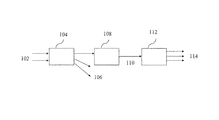
- FIG. 1 is a block diagram that illustrates an overview of the system
- FIG. 2 is a sample radar image from the Weather Underground website
- FIG. 3 illustrates how each radar frame represents reflectivity from the sky above a particular geographic location
- FIG. 4 is the NOAA's table of conversion from dbZ to rainfall.
- FIG. 5 is a block diagram showing the way in which a WeMo switch may be used to interrupt a sprinkler pump
- FIG. 6 is an electrical diagram of the block diagram of FIG. 5 showing the BelkinWeMo operating as a simple switch that opens or closes a relay;
- FIG. 7 illustrates the use of a WeMo switch that can interrupt the common wire.
- This invention resides in a Smart Sprinkler System (SSS) that uses rainfall information, from radar and other weather data obtained from the Internet, to send a control signal to a sprinkler system power controller that will either interrupt or enable power to the sprinkler system.
- SSS Smart Sprinkler System
- No local weather sensors or intelligence are required at the sprinkler system site and the device may be used in conjunction with existing sprinkler timers.
- From the Internet historical radar and other weather information, in addition to forecast precipitation information is used to make a decision to enable or disable the solenoids of the sprinkler system.
- An algorithm which compares the rainfall amount of the last several days and predicted rainfall for the next day(s), to a required rainfall threshold, will determine the decision to water.
- FIG. 1 is a block diagram that illustrates an overview of the system.
- the system includes at least one service center 104 receiving weather information 102 .
- the service center 104 sends out sprinkler ON/OFF (i.e., activation/deactivation signals) 106 to a plurality of sprinkler controllers 108 .
- the sprinkler controllers enable/disable power according to the ON/OFF signals 110 to the sprinkler solenoids (or both solenoids and timer) 112 operative to activate sprinkler zones 114 .
- sprinkler ON/OFF i.e., activation/deactivation signals
- the sprinkler controllers enable/disable power according to the ON/OFF signals 110 to the sprinkler solenoids (or both solenoids and timer) 112 operative to activate sprinkler zones 114 .
- the intelligence of the SSS resides at the Service Center. It is anticipated that there will be at least one service center associated with a given geographical area, and that each geographical area will include numerous commercial or residential sprinkler timers controlled by each center. While a given Service Center may include human personnel, in the preferred embodiment, all control signals are sent out entirely on an automated basis.
- local radar rainfall data, forecast information, and other weather data are collected from the Internet on a daily basis.
- the radar images are converted to rainfall rates using known conversion methods.
- the predicted rates may be corrected by available rain gauge data and/or other weather information.
- Historical and predicted rainfall information are used to decide whether or not to allow watering at each location that is timer-controlled by the system, and the decisions are delivered via signals 106 , shown in FIG. 1 .
- a primary source of precipitation information for a user's site will be from radar images for the user's location, obtained over the Internet.
- radar images There are now different types of radar images available, and the invention is not limited in terms of acquisition technology.
- Some images use Base Reflectivity, which is a display of echo intensity (reflectivity) measured in dBZ (decibels of Z, where Z represents the energy reflected back to the radar).
- Base Reflectivity images are available at several different elevation angles (tilts) of the antenna and are used to detect precipitation, evaluate storm structure, locate atmospheric boundaries and determine hail potential.
- Composite Reflectivity which displays maximum echo intensity (reflectivity) from any elevation angle at every range from the radar
- One-Hour Precipitation which is an image of estimated one-hour precipitation accumulation on a 1.1 nm by 1 degree grid, is used to assess rainfall intensities for flash flood warnings, urban flood statements and special weather statements
- Storm Total Precipitation is an estimate of accumulated rainfall, continuously updated, since the last one-hour break in precipitation. This product is used to locate flood potential over urban or rural areas, estimate total basin runoff and provide rainfall accumulations for the duration of the event; and services similar to StormTrac (cbs12.com/weather/features/animating-radar) which provides near-term prediction of where a rain cell will be in the next several hours.
- the invention is not limited in terms of the radar technology, and may use any available imagery, including yet-to-be developed, higher-resolution modalities.
- the input to the system is the analyzed radar image (dBZ intensity), with the output being average color which is indicative of estimated rainfall.
- the colors of the pixel(s) in the images represent radar reflectivity values measured in dBZ. These values are then converted into rainfall rates (see: desktopdoppler.com/help/nws-nextrad.htm).
- FIG. 2 is a sample radar image from the Weather Underground website (www.weather.com). On a periodic basis, for example every 5 minutes, a frame of data is downloaded from the website, and each frame represents the radar reflectivity from the sky above a particular geographic location, as shown in FIG. 3 .
- FIG. 4 is the NOAA's table of conversion from dbZ to rainfall. Each color translates dBZ to a numerical value, and each numerical value is added to the daily summary. In accordance with the invention, each day, the system generates an estimated rainfall for a plurality of geographical regions.
- the user's Zip Code (Zip+4) can be used to identify the user's location and default soil/grass type.
- the algorithm makes decisions based on recent watering events, or whether or not a quantum of rain has recently fallen or is predicted to occur within 24-hrs.
- a quantum of rain is defined as the output of a typical sprinkler head during a watering event and is proportional to the duration of a watering event. This value will be adjustable by the user according to individual watering desires.
- a combination of both historical and forecast precipitation (and other weather information) will be used to decide whether to water on a given day.
- the sprinkler timer will be set to water every day of the week. This means that the system is not limited to a fixed pattern of watering and is able to water on any day, i.e. has a variable pattern. Because of the this capability, incorrect rain predictions have little real effect on watering efficiency, since watering will occur the following day, due to the lack of historical rain. In fact, it can be shown that this ability to water on any day is inherently superior to any system that has a fixed pattern of watering. To demonstrate this, consider a lawn that requires watering only once every seven days. Here is an illustration of watering frequency, comparing a system using a fixed pattern of watering vs. a system using a variable pattern of watering:
- Example 1 compares what would happen in both systems under drought conditions with no rain. The watering events are identical. This example illustrates that the variable pattern employed by the invention performs no worse than the fixed pattern under drought conditions.
- Example 2 it rained at least a quantum of water on the eleventh day (indicated by shading).
- the fixed pattern system must water on the 15 th day, since the next opportunity to water would be on the 22 nd day, and that would result in an unacceptable period without water (i.e., 14 days). Since the variable pattern system can water on any day, it delays watering until the 18 th day, already an improvement over the fixed pattern system.
- Example 3 on the 14 th day, rain was forecast for the 15 th day (indicated by the letter ‘F’). The forecast was correct and it rained on the 15 th day (indicated by shading). It is observed that the variable pattern system is able to skip watering on the 15 th day. This results in a delay in watering until the 22 nd day. The fixed pattern system must water on the 15 th day.
- Example 4 on the 14 th day, rain was forecast for the 15 th day (indicated by the letter ‘F’). The forecast was incorrect and it did not rain on the 15 th . This is the worst-case scenario for the variable pattern system. It can be observed that the variable pattern algorithm skips watering on the 15 th . However, watering occurs the following day due to the lack of previous rain, and prevents any practical adverse effect on the irrigated area. This is a “self-healing” property of the variable pattern. The fixed pattern system has no such self-healing capability, since it cannot water until the next scheduled watering day. The possibility of a missed forecast appears to show potential worse performance for the variable pattern system.
- variable pattern system must be superior to any fixed pattern system, and the fact that the system can water on any day makes the variable pattern system possible.
- the SSS requires that all pins be pulled on the wheel that sets the day-frequency of watering on the pre-existing electromechanical sprinkler timer (or the equivalent procedure performed on an electronic timer) to allow for the capability of watering on any day.
- the percentage value used for ‘high probability’ and the default quantum value may be adjusted as more empirical evidence is gathered.
- the value of n is the number of days that a quantum of rain has not fallen and has a default value of 2, however, it is also adjustable according to the user's desires.
- the algorithm may also adjust the number of days to delay watering, proportional to the actual number of quanta of actual rainfall.
- Other relevant weather information e.g., temperature, wind
- user information e.g. soil type, grass type
- the algorithm decision uses rainfall data information, rain forecast and previous client recorded decisions as inputs to make the next-day decision for each client.
- Watering decisions are calculated per location, depending on location watering requirement, watering and rainfall history, and rainfall prediction/forecast. These decisions are recorded at the Service Center.
- the Service Center then transmits the decision to each Sprinkler System Power Controller at the appropriate time.
- This scheduled event e.g., an email or a scheduled Google Calendar event
- IFTTT If This Then That.
- exactly one ON or OFF signal is sent from the Service Center to each client site, every 24 hours, and zone timing is performed by the pre-existing sprinkler timer settings.
- the Sprinkler System Power Controller 108 will inhibit or allow power to the solenoids (or both solenoids and timer) of a sprinkler system equipped with a pre-existing electronic or electromechanical sprinkler timer 112 .
- the Sprinkler System Power Controller connects to the sprinkler system through the rain sensor inputs to the timer, if available. Otherwise, the Sprinkler System Power Controller will be connected to the sprinkler system through standard home circuitry wiring and will control power to the sprinkler system by interrupting the common wire. See http://waterheatertimer.org/How-to-wire-Intermatic-sprinkler-timers.html for examples of electromechanical sprinkler timers with and without rain sensor terminals.
- FIG. 5 is a block diagram showing the way in which a WeMo switch may be used to interrupt a sprinkler pump.
- FIG. 6 is an electrical diagram of the block diagram of FIG. 5 showing the BelkinWeMo operating as a simple switch that opens or closes a relay.
- FIG. 7 illustrates the use of a WeMo switch that can interrupt the common wire.
- CallerID may be used.
- a message is sent from a particular phone number, and when the message is received, recognition of that phone number enables the sprinkler system.
- the “content” of the message is immaterial.
- recognition of that phone number disables the sprinkler system. If no signals are received in 24 hr period, the system reverts to the predetermined watering schedule when there is no rain, in which case the sprinkler system delivers the desired amount of water following a predetermined number of days, n, without watering.
- the recognition of a valid CallerID is received (i.e., turn the system ON/OFF), the system automatically takes the phone off-hook momentarily then hangs up. This accomplishes two things. First, this prevents multiple, longer-teen ringing of the phone, and secondly, pick-up and hang-up serves as a confirmation to the caller that the message was indeed received.
- the sprinkler controller precisely controls watering by allowing or interrupting power to the sprinkler at desired times, based on historical and forecast rainfall and other weather information acquired by the Service Center.
- This invention can make use of either mode of operation for any style of controller, though the AUTO mode is preferred.
- the sprinkler system power controller inhibits watering by the sprinkler for any 24-hour period by interrupting power to the sprinkler system based the signals received from the Service Center. This is the preferred embodiment.
- the daily sprinkler timing is controlled by the pre-existing sprinkler timer.
- the pre-existing sprinkler timer will be set to water every day, and when power is supplied to the sprinkler system in this mode, watering will occur according to the schedule determined by the pins in an electromechanical sprinkler timer or by the schedule programmed into an electronic timer.
- the sprinkler timer is set to the ON mode and causes the sprinkler system to water whenever there is power supplied to the sprinkler system.
- the sprinkler system power controller precisely controls watering by allowing or interrupting power to the sprinkler in accordance with the signals received from the Service Center.
- the pre-existing sprinkler timer never controls sprinkler timing; sprinkler individual zone watering is at all times controlled by timed signals from the Service Center.
- This example pertains to an electronic programmable timer or an electromechanical timer set to AUTO (i.e., watering occurs according to the zone durations set by the pins).
- the sprinkler timer schedule is set to water every day of the week and is identical for all days of the week.
- the algorithm will either inhibit or permit watering based on historical and/or forecast weather information, and a signal is received from the Internet to open or close the switch in the Sprinkler System Power Controller.
- the switch closes when watering is desired.
- the switch opens to inhibit watering.
- pre-existing timer In order to maintain rotational synchronicity, power to the pre-existing timer is maintained even when power to the sprinklers is interrupted. In the case where a rain sensor is available or where the common wire is interrupted, inhibition of sprinkling for periods of 24-hrs. is preferred since the pre-existing timer can be used for zone timing and only a single pair of ON/OFF signals would be needed when watering for any particular day.
- This example pertains to an electromechanical timer set to AUTO, where power to the home circuitry is interrupted. Operation is same as in EXAMPLE 1, except that power interruption must be for 24-hr. periods and zone timing is controlled by the pre-existing sprinkler timer. Power is interrupted to both the sprinkler solenoids and the electromechanical timer. Therefore, power interruption must be for 24-hr. periods so that the timer maintains rotational synchronicity with the 24-hr. cycle.
- This example pertains to an electromechanical timer set to ON (i.e., the sprinkler continues to water as long as power is supplied; when power is restored after it has been interrupted, the sprinkler indexes to the next zone and continues watering).
- the timer settings of the existing sprinkler timer are not used. Instead, all timing is controlled by appropriate power ON/OFF signals sent to the Sprinkler System Power Controller.
- the Service Center sends timed signals to water in accordance with the desired length of watering time for each zone.
- the system is initially sent a signal to interrupt power so that watering does not begin until the watering cycle is to start.
- power is restored to the system to begin watering the first zone.
- a power interruption signal is sent at the end of the watering duration for that zone.
- power is restored to the system, causing the system to index to the next zone and resume watering. This process continues until all zones have been completed and the final zone receives its termination signal and interrupts power.
- a daughter board that incorporates a timing circuit may be integrated in this embodiment to prevent the system from excess watering due to a communications failure.
Abstract
Description
-
- a) follow a predetermined watering schedule when there is no rain, in which case the sprinkler system delivers the desired amount of water following a predetermined number of days, n, without watering, or
- b) increase n by 1 or more days if the rainfall information indicates at least one significant rain event capable of providing the desired amount of water, and
- c) return to a) when n expires.
-
- The area to be watered requires at least a quantum of water every seven days.
- The fixed pattern system is only permitted to water every seventh day.
- The variable pattern system may water on any day.
| Day: | 1 | 2 | 3 | 4 | 5 | 6 | 7 |
| Fixed: | Watering | ||||||
| Variable: | Watering | ||||||
| Day: | 8 | 9 | 10 | 11 | 12 | 13 | 14 |
| Fixed: | Watering | ||||||
| Variable: | Watering | ||||||
| Day: | 15 | 16 | 17 | 18 | 19 | 20 | 21 |
| Fixed: | Watering | ||||||
| Variable: | Watering | ||||||
 |
 |
| Day: | 1 | 2 | 3 | 4 | 5 | 6 | 7 |
| Fixed: | Watering | ||||||
| Variable: | Watering | ||||||
| Day: | 8 | 9 | 10 | 11 F | 12 | 13 | 14 F |
| Fixed: | Watering | ||||||
| Variable: | Watering | ||||||
| Day: | 15 | 16 | 17 | 18 | 19 | 20 | 21 |
| Fixed: | Watering | ||||||
| Variable: | Watering | ||||||
-
- IF an area forecast shows a high probability of at least a quantum of rain in the next 24 hrs.,
- Do not Water
- OR ELSE IF a StormTrac radar indicates that a rain cell will cause a quantum of rain to fall on the user's location in the next 2 hrs.
- Do not Water
- OR ELSE IF watering or rainfall has occurred in the past n days,
- Do not Water
- OR ELSE
- Water
- IF an area forecast shows a high probability of at least a quantum of rain in the next 24 hrs.,
Claims (61)
Priority Applications (3)
| Application Number | Priority Date | Filing Date | Title |
|---|---|---|---|
| US13/966,869 US9504213B2 (en) | 2012-11-26 | 2013-08-14 | Smart sprinkler system with variable scheduling and radar-based rainfall information |
| US15/297,298 US10101753B1 (en) | 2012-11-26 | 2016-10-19 | Auxiliary sprinkler controller for a smart sprinkler system and method of operating same |
| US15/299,784 US10225997B1 (en) | 2012-11-26 | 2016-10-21 | Smart sprinkler system and method |
Applications Claiming Priority (2)
| Application Number | Priority Date | Filing Date | Title |
|---|---|---|---|
| US201261729842P | 2012-11-26 | 2012-11-26 | |
| US13/966,869 US9504213B2 (en) | 2012-11-26 | 2013-08-14 | Smart sprinkler system with variable scheduling and radar-based rainfall information |
Related Child Applications (2)
| Application Number | Title | Priority Date | Filing Date |
|---|---|---|---|
| US15/297,298 Continuation-In-Part US10101753B1 (en) | 2012-11-26 | 2016-10-19 | Auxiliary sprinkler controller for a smart sprinkler system and method of operating same |
| US15/299,784 Continuation-In-Part US10225997B1 (en) | 2012-11-26 | 2016-10-21 | Smart sprinkler system and method |
Publications (2)
| Publication Number | Publication Date |
|---|---|
| US20140148959A1 US20140148959A1 (en) | 2014-05-29 |
| US9504213B2 true US9504213B2 (en) | 2016-11-29 |
Family
ID=50773947
Family Applications (1)
| Application Number | Title | Priority Date | Filing Date |
|---|---|---|---|
| US13/966,869 Active 2033-12-30 US9504213B2 (en) | 2012-11-26 | 2013-08-14 | Smart sprinkler system with variable scheduling and radar-based rainfall information |
Country Status (1)
| Country | Link |
|---|---|
| US (1) | US9504213B2 (en) |
Cited By (6)
| Publication number | Priority date | Publication date | Assignee | Title |
|---|---|---|---|---|
| US9984455B1 (en) * | 2017-06-05 | 2018-05-29 | Hana Resources, Inc. | Organism growth prediction system using drone-captured images |
| US10225997B1 (en) * | 2012-11-26 | 2019-03-12 | Michael R. Levine | Smart sprinkler system and method |
| US10274969B2 (en) * | 2014-05-06 | 2019-04-30 | Rachio, Inc. | System and method for an improved sprinkler control system |
| US10458880B2 (en) * | 2017-06-06 | 2019-10-29 | Michael R. Levine | Method and apparatus for leak detection in an irrigation system |
| US11074447B1 (en) | 2018-07-13 | 2021-07-27 | Hana Resources, Inc. | Land analysis system using drone-captured data |
| US11234378B2 (en) | 2019-04-16 | 2022-02-01 | FPL Smart Services, LLC | Image based irrigation control |
Families Citing this family (7)
| Publication number | Priority date | Publication date | Assignee | Title |
|---|---|---|---|---|
| US9144204B2 (en) | 2006-06-20 | 2015-09-29 | Rain Bird Corporation | User interface for a sensor-based interface device for interrupting an irrigation controller |
| WO2007149949A1 (en) | 2006-06-20 | 2007-12-27 | Rain Bird Corporation | Sensor device for interrupting irrigation |
| CN105191759A (en) * | 2015-09-10 | 2015-12-30 | 太仓市秀兴农场专业合作社 | Agricultural irrigation system |
| US10390501B1 (en) | 2017-04-04 | 2019-08-27 | Technology West, LLC | Sprinkler control system |
| US10444769B2 (en) | 2017-04-24 | 2019-10-15 | Rain Bird Corporation | Sensor-based interruption of an irrigation controller |
| US10757873B2 (en) * | 2017-04-24 | 2020-09-01 | Rain Bird Corporation | Sensor-based interruption of an irrigation controller |
| WO2019133273A1 (en) | 2017-12-29 | 2019-07-04 | Rain Bird Corporation | Weather override irrigation control systems and methods |
Citations (23)
| Publication number | Priority date | Publication date | Assignee | Title |
|---|---|---|---|---|
| US3886378A (en) * | 1973-11-08 | 1975-05-27 | Clemar Mfg Corp | Timing unit for connecting power sequentially to a plurality of stations |
| US5761312A (en) * | 1995-06-07 | 1998-06-02 | Zelikovitz, Deceased; Joseph | Enhanced individual intelligent communication platform for subscribers on a telephone system |
| WO1999048354A1 (en) | 1998-03-20 | 1999-09-30 | Irrigation Control Networks Pty. Ltd. | Irrigation control system |
| US6314340B1 (en) * | 1998-11-02 | 2001-11-06 | Telsco Industries | Irrigation controller |
| US6452499B1 (en) | 1998-10-07 | 2002-09-17 | Thomas Henry Runge | Wireless environmental sensor system |
| US20030093159A1 (en) * | 2001-11-05 | 2003-05-15 | James Sieminski | Internet-enabled central irrigation control |
| WO2005062961A2 (en) | 2003-12-23 | 2005-07-14 | Rain Bird Corporation | Modular and expandable irrigation controller |
| US20050273205A1 (en) * | 2002-10-15 | 2005-12-08 | Rain Bird Corporation | Modular and expandable irrigation controller |
| US20060100747A1 (en) | 2002-10-24 | 2006-05-11 | Runge Thomas H | Intelligent environmental sensor for irrigation systems |
| US20070293990A1 (en) | 2003-04-25 | 2007-12-20 | George Alexanain | Irrigation water conservation with temperature budgeting and time of use technology |
| WO2007149949A1 (en) | 2006-06-20 | 2007-12-27 | Rain Bird Corporation | Sensor device for interrupting irrigation |
| US20080147205A1 (en) * | 2006-12-18 | 2008-06-19 | General Instrument Corporation | Method and System for Controlling Devices in a Network |
| US20080234870A1 (en) * | 2007-03-23 | 2008-09-25 | Ibm Corporation | Irrigation System and Methodology |
| WO2009002757A2 (en) | 2007-06-22 | 2008-12-31 | Rain Bird Corporation | Code replacement for irrigation controllers |
| US7552632B2 (en) | 2006-08-08 | 2009-06-30 | The Toro Company | Raindrop sensor for an irrigation system |
| US20090316671A1 (en) * | 2008-05-16 | 2009-12-24 | La Crosse Technology, Ltd. | Method and Apparatus of Transmitting, Receiving, Displaying and Playing Weather Data |
| EP2201834A1 (en) | 2007-07-13 | 2010-06-30 | Samcla-Esic, S.L. | Centralised, automated and remote watering system |
| WO2011044289A1 (en) | 2009-10-07 | 2011-04-14 | Rain Bird Corporation | Volumetric budget based irrigation control |
| EP2342965A1 (en) | 2010-01-06 | 2011-07-13 | Deere & Company | Varying irrigation scheduling based on height of vegetation |
| US7996192B2 (en) | 2005-05-28 | 2011-08-09 | Dblive Corporation | Method and apparatus for generating an environmental element prediction for a point of interest |
| EP2354878A1 (en) | 2010-02-02 | 2011-08-10 | Deere & Company | Method for regenerating a boundary containing a mobile robot |
| US20110237227A1 (en) | 2010-03-25 | 2011-09-29 | T-Mobile Usa, Inc. | Chore and Rewards Tracker |
| US20120215366A1 (en) | 2006-06-20 | 2012-08-23 | Rain Bird Corporation | User interface for a sensor-based interface device for interrupting an irrigation controller |
-
2013
- 2013-08-14 US US13/966,869 patent/US9504213B2/en active Active
Patent Citations (30)
| Publication number | Priority date | Publication date | Assignee | Title |
|---|---|---|---|---|
| US3886378A (en) * | 1973-11-08 | 1975-05-27 | Clemar Mfg Corp | Timing unit for connecting power sequentially to a plurality of stations |
| US5761312A (en) * | 1995-06-07 | 1998-06-02 | Zelikovitz, Deceased; Joseph | Enhanced individual intelligent communication platform for subscribers on a telephone system |
| WO1999048354A1 (en) | 1998-03-20 | 1999-09-30 | Irrigation Control Networks Pty. Ltd. | Irrigation control system |
| US6452499B1 (en) | 1998-10-07 | 2002-09-17 | Thomas Henry Runge | Wireless environmental sensor system |
| US6314340B1 (en) * | 1998-11-02 | 2001-11-06 | Telsco Industries | Irrigation controller |
| US20030093159A1 (en) * | 2001-11-05 | 2003-05-15 | James Sieminski | Internet-enabled central irrigation control |
| US20050273205A1 (en) * | 2002-10-15 | 2005-12-08 | Rain Bird Corporation | Modular and expandable irrigation controller |
| US20060100747A1 (en) | 2002-10-24 | 2006-05-11 | Runge Thomas H | Intelligent environmental sensor for irrigation systems |
| US20070293990A1 (en) | 2003-04-25 | 2007-12-20 | George Alexanain | Irrigation water conservation with temperature budgeting and time of use technology |
| WO2005062961A2 (en) | 2003-12-23 | 2005-07-14 | Rain Bird Corporation | Modular and expandable irrigation controller |
| US8265797B2 (en) | 2003-12-23 | 2012-09-11 | Rain Bird Corporation | Modular and expandable irrigation controller |
| US7996192B2 (en) | 2005-05-28 | 2011-08-09 | Dblive Corporation | Method and apparatus for generating an environmental element prediction for a point of interest |
| US20120035898A1 (en) | 2005-05-28 | 2012-02-09 | Carlos Repelli | Method and apparatus for generating an environmental element prediction for a point of interest |
| US7949433B2 (en) | 2006-06-20 | 2011-05-24 | Rain Bird Corporation | Sensor device for interrupting irrigation |
| US20120215366A1 (en) | 2006-06-20 | 2012-08-23 | Rain Bird Corporation | User interface for a sensor-based interface device for interrupting an irrigation controller |
| WO2007149949A1 (en) | 2006-06-20 | 2007-12-27 | Rain Bird Corporation | Sensor device for interrupting irrigation |
| US20120229284A1 (en) | 2006-06-20 | 2012-09-13 | Rain Bird Corporation | Sensor device for use in controlling irrigation |
| US20110224836A1 (en) | 2006-06-20 | 2011-09-15 | Rain Bird Corporation | Sensor device for interrupting irrigation |
| US20080027586A1 (en) * | 2006-06-20 | 2008-01-31 | Rain Bird Corporation | Sensor Device For Interrupting Irrigation |
| US7552632B2 (en) | 2006-08-08 | 2009-06-30 | The Toro Company | Raindrop sensor for an irrigation system |
| US20080147205A1 (en) * | 2006-12-18 | 2008-06-19 | General Instrument Corporation | Method and System for Controlling Devices in a Network |
| US20080234870A1 (en) * | 2007-03-23 | 2008-09-25 | Ibm Corporation | Irrigation System and Methodology |
| WO2009002757A2 (en) | 2007-06-22 | 2008-12-31 | Rain Bird Corporation | Code replacement for irrigation controllers |
| EP2201834A1 (en) | 2007-07-13 | 2010-06-30 | Samcla-Esic, S.L. | Centralised, automated and remote watering system |
| US20090316671A1 (en) * | 2008-05-16 | 2009-12-24 | La Crosse Technology, Ltd. | Method and Apparatus of Transmitting, Receiving, Displaying and Playing Weather Data |
| WO2011044289A1 (en) | 2009-10-07 | 2011-04-14 | Rain Bird Corporation | Volumetric budget based irrigation control |
| US20120239211A1 (en) | 2009-10-07 | 2012-09-20 | Rain Bird Corporation | Volumetric budget based irrigation control |
| EP2342965A1 (en) | 2010-01-06 | 2011-07-13 | Deere & Company | Varying irrigation scheduling based on height of vegetation |
| EP2354878A1 (en) | 2010-02-02 | 2011-08-10 | Deere & Company | Method for regenerating a boundary containing a mobile robot |
| US20110237227A1 (en) | 2010-03-25 | 2011-09-29 | T-Mobile Usa, Inc. | Chore and Rewards Tracker |
Cited By (11)
| Publication number | Priority date | Publication date | Assignee | Title |
|---|---|---|---|---|
| US10225997B1 (en) * | 2012-11-26 | 2019-03-12 | Michael R. Levine | Smart sprinkler system and method |
| US10274969B2 (en) * | 2014-05-06 | 2019-04-30 | Rachio, Inc. | System and method for an improved sprinkler control system |
| US20190250646A1 (en) * | 2014-05-06 | 2019-08-15 | Rachio, Inc. | Irrigation control utilizing water authority data |
| US11150672B2 (en) * | 2014-05-06 | 2021-10-19 | Rachio, Inc. | Irrigation control utilizing water authority data |
| US11675375B2 (en) | 2014-05-06 | 2023-06-13 | Rachio, Inc. | Residential water utilization tracking |
| US9984455B1 (en) * | 2017-06-05 | 2018-05-29 | Hana Resources, Inc. | Organism growth prediction system using drone-captured images |
| US20180350054A1 (en) * | 2017-06-05 | 2018-12-06 | Hana Resources, Inc. | Organism growth prediction system using drone-captured images |
| US10713777B2 (en) * | 2017-06-05 | 2020-07-14 | Hana Resources, Inc. | Organism growth prediction system using drone-captured images |
| US10458880B2 (en) * | 2017-06-06 | 2019-10-29 | Michael R. Levine | Method and apparatus for leak detection in an irrigation system |
| US11074447B1 (en) | 2018-07-13 | 2021-07-27 | Hana Resources, Inc. | Land analysis system using drone-captured data |
| US11234378B2 (en) | 2019-04-16 | 2022-02-01 | FPL Smart Services, LLC | Image based irrigation control |
Also Published As
| Publication number | Publication date |
|---|---|
| US20140148959A1 (en) | 2014-05-29 |
Similar Documents
| Publication | Publication Date | Title |
|---|---|---|
| US9504213B2 (en) | Smart sprinkler system with variable scheduling and radar-based rainfall information | |
| US10101753B1 (en) | Auxiliary sprinkler controller for a smart sprinkler system and method of operating same | |
| US6895987B2 (en) | Device that modifies irrigation schedules of existing irrigation controllers | |
| US10743482B2 (en) | Central irrigation control system | |
| US10716269B2 (en) | Methods and systems for irrigation control | |
| US6298285B1 (en) | Irrigation accumulation controller | |
| US20040011880A1 (en) | Device that modifies irrigation schedules of existing irrigation controllers | |
| US7096094B2 (en) | Automatic irrigation frequency adjustment for deep watering | |
| US10362739B2 (en) | Methods and systems for irrigation control | |
| US8170721B2 (en) | Automatically adjusting irrigation controller | |
| US5870302A (en) | Evapotranspiration remote irrigation control system | |
| US8874275B2 (en) | Landscape irrigation management with automated water budget and seasonal adjust, and automated implementation of watering restrictions | |
| US20160198645A1 (en) | Irrigation control systems and methods | |
| US20070185621A1 (en) | System and method for controlling injection into an irrigation system | |
| CN107278832A (en) | Farmland intelligent water-saving irrigation system and method | |
| US10225997B1 (en) | Smart sprinkler system and method | |
| KR20210097860A (en) | Smart farm system for vineyard can block rain and generate solar power | |
| JP6870448B2 (en) | Fine mist cooling system and fine mist cooling method used in cultivation facilities | |
| US20120286062A1 (en) | Network based sprinkler controller | |
| US7258129B1 (en) | Moisture sensor and control system for sprinklers and method therefor | |
| JP2021191247A (en) | Watering management system | |
| AU1492501A (en) | Modifying irrigation schedules of existing irrigation controllers | |
| Heermann et al. | Integrated water-energy management system for center pivot irrigation: implementation | |
| WO2017145180A1 (en) | Method and apparatus for scanning and estimating moisture in soil | |
| AU2001246089A1 (en) | Automatic irrigation frequency adjustment for deep watering |
Legal Events
| Date | Code | Title | Description |
|---|---|---|---|
| AS | Assignment |
Owner name: LEVINE, MICHAEL R., MICHIGAN Free format text: ASSIGNMENT OF ASSIGNORS INTEREST;ASSIGNOR:DICKENS, LUKE;REEL/FRAME:031208/0966 Effective date: 20130820 |
|
| STCF | Information on status: patent grant |
Free format text: PATENTED CASE |
|
| MAFP | Maintenance fee payment |
Free format text: PAYMENT OF MAINTENANCE FEE, 4TH YR, SMALL ENTITY (ORIGINAL EVENT CODE: M2551); ENTITY STATUS OF PATENT OWNER: SMALL ENTITY Year of fee payment: 4 |
|
| AS | Assignment |
Owner name: SUSTAINABLE SPRINKLER, INC., FLORIDA Free format text: ASSIGNMENT OF ASSIGNORS INTEREST;ASSIGNOR:LEVINE, MICHAEL R.;REEL/FRAME:054762/0785 Effective date: 20201223 |
|
| AS | Assignment |
Owner name: SUSTAINSPRINKLE LLC, FLORIDA Free format text: ENTITY CONVERSION;ASSIGNOR:SUSTAINSPRINKLE INC.;REEL/FRAME:055344/0834 Effective date: 20160614 |
|
| AS | Assignment |
Owner name: SUSTAINSPRINKLE LLC, FLORIDA Free format text: CORRECTIVE ASSIGNMENT TO CORRECT THE RECEIVING PARTY NAME AND ADDRESS PREVIOUSLY RECORDED AT REEL: 54762 FRAME: 785. ASSIGNOR(S) HEREBY CONFIRMS THE ASSIGNMENT;ASSIGNOR:LEVINE, MICHAEL R.;REEL/FRAME:056500/0901 Effective date: 20201223 |
|
| AS | Assignment |
Owner name: SUSTAINSPRINKLE LLC, FLORIDA Free format text: CORRECTIVE ASSIGNMENT TO CORRECT THE ASSIGNEE ADDRESS PREVIOUSLY RECORDED AT REEL: 056500 FRAME: 0901. ASSIGNOR(S) HEREBY CONFIRMS THE ASSIGNMENT;ASSIGNOR:LEVINE, MICHAEL R.;REEL/FRAME:060649/0405 Effective date: 20201223 |
|
| AS | Assignment |
Owner name: SUSTAINABLE SAVINGS LLC, FLORIDA Free format text: ASSIGNMENT OF ASSIGNORS INTEREST;ASSIGNOR:SUSTAINSPRINKLE LLC;REEL/FRAME:061303/0075 Effective date: 20220714 |