US9503915B2 - Dynamic beamforming configuration based on network conditions - Google Patents
Dynamic beamforming configuration based on network conditions Download PDFInfo
- Publication number
- US9503915B2 US9503915B2 US13/857,314 US201313857314A US9503915B2 US 9503915 B2 US9503915 B2 US 9503915B2 US 201313857314 A US201313857314 A US 201313857314A US 9503915 B2 US9503915 B2 US 9503915B2
- Authority
- US
- United States
- Prior art keywords
- access point
- candidate access
- client device
- access points
- client devices
- Prior art date
- Legal status (The legal status is an assumption and is not a legal conclusion. Google has not performed a legal analysis and makes no representation as to the accuracy of the status listed.)
- Active, expires
Links
- 230000005540 biological transmission Effects 0.000 claims abstract description 42
- 238000000034 method Methods 0.000 claims abstract description 25
- 238000012360 testing method Methods 0.000 claims description 14
- 230000008859 change Effects 0.000 claims description 6
- 238000004891 communication Methods 0.000 abstract description 11
- 239000011159 matrix material Substances 0.000 description 12
- 230000004044 response Effects 0.000 description 7
- 238000013500 data storage Methods 0.000 description 6
- 238000012545 processing Methods 0.000 description 6
- 238000013459 approach Methods 0.000 description 5
- 238000010586 diagram Methods 0.000 description 5
- 238000005562 fading Methods 0.000 description 5
- 230000008901 benefit Effects 0.000 description 3
- 238000000354 decomposition reaction Methods 0.000 description 2
- 238000001514 detection method Methods 0.000 description 2
- 230000006870 function Effects 0.000 description 2
- 230000007246 mechanism Effects 0.000 description 2
- 230000003287 optical effect Effects 0.000 description 2
- 238000012856 packing Methods 0.000 description 2
- 239000004065 semiconductor Substances 0.000 description 2
- 238000003860 storage Methods 0.000 description 2
- 239000000654 additive Substances 0.000 description 1
- 230000000996 additive effect Effects 0.000 description 1
- 230000002776 aggregation Effects 0.000 description 1
- 238000004220 aggregation Methods 0.000 description 1
- 238000004364 calculation method Methods 0.000 description 1
- 238000012512 characterization method Methods 0.000 description 1
- 230000002301 combined effect Effects 0.000 description 1
- 238000012937 correction Methods 0.000 description 1
- 230000008713 feedback mechanism Effects 0.000 description 1
- 238000005304 joining Methods 0.000 description 1
- 238000007726 management method Methods 0.000 description 1
- 238000004519 manufacturing process Methods 0.000 description 1
- 238000004377 microelectronic Methods 0.000 description 1
- 230000002093 peripheral effect Effects 0.000 description 1
- 230000002085 persistent effect Effects 0.000 description 1
- 230000008569 process Effects 0.000 description 1
- 230000000644 propagated effect Effects 0.000 description 1
- 239000000523 sample Substances 0.000 description 1
- 238000012549 training Methods 0.000 description 1
- 238000012546 transfer Methods 0.000 description 1
Images


Classifications
-
- H—ELECTRICITY
- H04—ELECTRIC COMMUNICATION TECHNIQUE
- H04W—WIRELESS COMMUNICATION NETWORKS
- H04W24/00—Supervisory, monitoring or testing arrangements
- H04W24/02—Arrangements for optimising operational condition
-
- H—ELECTRICITY
- H04—ELECTRIC COMMUNICATION TECHNIQUE
- H04B—TRANSMISSION
- H04B7/00—Radio transmission systems, i.e. using radiation field
- H04B7/02—Diversity systems; Multi-antenna system, i.e. transmission or reception using multiple antennas
- H04B7/04—Diversity systems; Multi-antenna system, i.e. transmission or reception using multiple antennas using two or more spaced independent antennas
- H04B7/06—Diversity systems; Multi-antenna system, i.e. transmission or reception using multiple antennas using two or more spaced independent antennas at the transmitting station
- H04B7/0602—Diversity systems; Multi-antenna system, i.e. transmission or reception using multiple antennas using two or more spaced independent antennas at the transmitting station using antenna switching
- H04B7/0608—Antenna selection according to transmission parameters
- H04B7/061—Antenna selection according to transmission parameters using feedback from receiving side
-
- H—ELECTRICITY
- H04—ELECTRIC COMMUNICATION TECHNIQUE
- H04L—TRANSMISSION OF DIGITAL INFORMATION, e.g. TELEGRAPHIC COMMUNICATION
- H04L47/00—Traffic control in data switching networks
- H04L47/10—Flow control; Congestion control
-
- H04W72/0486—
-
- H—ELECTRICITY
- H04—ELECTRIC COMMUNICATION TECHNIQUE
- H04W—WIRELESS COMMUNICATION NETWORKS
- H04W72/00—Local resource management
- H04W72/50—Allocation or scheduling criteria for wireless resources
- H04W72/52—Allocation or scheduling criteria for wireless resources based on load
-
- H—ELECTRICITY
- H04—ELECTRIC COMMUNICATION TECHNIQUE
- H04B—TRANSMISSION
- H04B7/00—Radio transmission systems, i.e. using radiation field
- H04B7/02—Diversity systems; Multi-antenna system, i.e. transmission or reception using multiple antennas
- H04B7/04—Diversity systems; Multi-antenna system, i.e. transmission or reception using multiple antennas using two or more spaced independent antennas
- H04B7/06—Diversity systems; Multi-antenna system, i.e. transmission or reception using multiple antennas using two or more spaced independent antennas at the transmitting station
- H04B7/0602—Diversity systems; Multi-antenna system, i.e. transmission or reception using multiple antennas using two or more spaced independent antennas at the transmitting station using antenna switching
- H04B7/0608—Antenna selection according to transmission parameters
-
- H—ELECTRICITY
- H04—ELECTRIC COMMUNICATION TECHNIQUE
- H04B—TRANSMISSION
- H04B7/00—Radio transmission systems, i.e. using radiation field
- H04B7/02—Diversity systems; Multi-antenna system, i.e. transmission or reception using multiple antennas
- H04B7/04—Diversity systems; Multi-antenna system, i.e. transmission or reception using multiple antennas using two or more spaced independent antennas
- H04B7/06—Diversity systems; Multi-antenna system, i.e. transmission or reception using multiple antennas using two or more spaced independent antennas at the transmitting station
- H04B7/0613—Diversity systems; Multi-antenna system, i.e. transmission or reception using multiple antennas using two or more spaced independent antennas at the transmitting station using simultaneous transmission
- H04B7/0615—Diversity systems; Multi-antenna system, i.e. transmission or reception using multiple antennas using two or more spaced independent antennas at the transmitting station using simultaneous transmission of weighted versions of same signal
- H04B7/0619—Diversity systems; Multi-antenna system, i.e. transmission or reception using multiple antennas using two or more spaced independent antennas at the transmitting station using simultaneous transmission of weighted versions of same signal using feedback from receiving side
- H04B7/0621—Feedback content
- H04B7/0626—Channel coefficients, e.g. channel state information [CSI]
-
- H—ELECTRICITY
- H04—ELECTRIC COMMUNICATION TECHNIQUE
- H04B—TRANSMISSION
- H04B7/00—Radio transmission systems, i.e. using radiation field
- H04B7/02—Diversity systems; Multi-antenna system, i.e. transmission or reception using multiple antennas
- H04B7/04—Diversity systems; Multi-antenna system, i.e. transmission or reception using multiple antennas using two or more spaced independent antennas
- H04B7/06—Diversity systems; Multi-antenna system, i.e. transmission or reception using multiple antennas using two or more spaced independent antennas at the transmitting station
- H04B7/0613—Diversity systems; Multi-antenna system, i.e. transmission or reception using multiple antennas using two or more spaced independent antennas at the transmitting station using simultaneous transmission
- H04B7/0615—Diversity systems; Multi-antenna system, i.e. transmission or reception using multiple antennas using two or more spaced independent antennas at the transmitting station using simultaneous transmission of weighted versions of same signal
- H04B7/0619—Diversity systems; Multi-antenna system, i.e. transmission or reception using multiple antennas using two or more spaced independent antennas at the transmitting station using simultaneous transmission of weighted versions of same signal using feedback from receiving side
- H04B7/0621—Feedback content
- H04B7/0632—Channel quality parameters, e.g. channel quality indicator [CQI]
-
- H04L12/5695—
-
- H—ELECTRICITY
- H04—ELECTRIC COMMUNICATION TECHNIQUE
- H04L—TRANSMISSION OF DIGITAL INFORMATION, e.g. TELEGRAPHIC COMMUNICATION
- H04L47/00—Traffic control in data switching networks
- H04L47/10—Flow control; Congestion control
- H04L47/11—Identifying congestion
-
- H—ELECTRICITY
- H04—ELECTRIC COMMUNICATION TECHNIQUE
- H04L—TRANSMISSION OF DIGITAL INFORMATION, e.g. TELEGRAPHIC COMMUNICATION
- H04L47/00—Traffic control in data switching networks
- H04L47/10—Flow control; Congestion control
- H04L47/15—Flow control; Congestion control in relation to multipoint traffic
-
- H—ELECTRICITY
- H04—ELECTRIC COMMUNICATION TECHNIQUE
- H04L—TRANSMISSION OF DIGITAL INFORMATION, e.g. TELEGRAPHIC COMMUNICATION
- H04L47/00—Traffic control in data switching networks
- H04L47/70—Admission control; Resource allocation
-
- H—ELECTRICITY
- H04—ELECTRIC COMMUNICATION TECHNIQUE
- H04W—WIRELESS COMMUNICATION NETWORKS
- H04W28/00—Network traffic management; Network resource management
- H04W28/02—Traffic management, e.g. flow control or congestion control
- H04W28/0289—Congestion control
-
- H—ELECTRICITY
- H04—ELECTRIC COMMUNICATION TECHNIQUE
- H04W—WIRELESS COMMUNICATION NETWORKS
- H04W72/00—Local resource management
- H04W72/04—Wireless resource allocation
- H04W72/044—Wireless resource allocation based on the type of the allocated resource
- H04W72/0453—Resources in frequency domain, e.g. a carrier in FDMA
-
- H—ELECTRICITY
- H04—ELECTRIC COMMUNICATION TECHNIQUE
- H04W—WIRELESS COMMUNICATION NETWORKS
- H04W72/00—Local resource management
- H04W72/04—Wireless resource allocation
- H04W72/044—Wireless resource allocation based on the type of the allocated resource
- H04W72/046—Wireless resource allocation based on the type of the allocated resource the resource being in the space domain, e.g. beams
-
- H04W72/085—
-
- H—ELECTRICITY
- H04—ELECTRIC COMMUNICATION TECHNIQUE
- H04W—WIRELESS COMMUNICATION NETWORKS
- H04W72/00—Local resource management
- H04W72/50—Allocation or scheduling criteria for wireless resources
- H04W72/54—Allocation or scheduling criteria for wireless resources based on quality criteria
- H04W72/542—Allocation or scheduling criteria for wireless resources based on quality criteria using measured or perceived quality
-
- H—ELECTRICITY
- H04—ELECTRIC COMMUNICATION TECHNIQUE
- H04W—WIRELESS COMMUNICATION NETWORKS
- H04W84/00—Network topologies
- H04W84/02—Hierarchically pre-organised networks, e.g. paging networks, cellular networks, WLAN [Wireless Local Area Network] or WLL [Wireless Local Loop]
- H04W84/10—Small scale networks; Flat hierarchical networks
- H04W84/12—WLAN [Wireless Local Area Networks]
Definitions
- the present disclosure relates to configuring access points based on network conditions in a wireless network.
- the present disclosure relates to steering client devices to access points that potentially increase capacity of communications using beamformed transmissions.
- wireless network devices Over the past decade, there has been a substantial increase in the use and deployment of wireless network devices, from dual-mode smartphones to tablets capable of operating in accordance with a particular Institute of Electrical and Electronics Engineers (IEEE) standard. With “wireless” becoming the de-facto medium for connectivity among users, it has become increasingly important for access points to intelligently manage connections with a plurality of client devices to maintain high throughput and avoid overprovisioning.
- IEEE Institute of Electrical and Electronics Engineers
- IEEE 802.11 supports multiple channel widths and optional beamforming capabilities. Network administrators are often forced to painstakingly individually adjust these parameters to increase network performance.
- FIG. 1 shows a block diagram example of a network in accordance with one or more embodiments
- FIG. 2 shows a block diagram example of an access point in accordance with one or more embodiments.
- FIG. 3 shows a method for steering client devices to access points that may increase capacity of an associated wireless channel in accordance with one or more embodiments.
- digital device generally refers to any hardware device that includes processing circuitry running at least one process adapted to control the flow of traffic into the device.
- digital devices include a computer, a tablet, a laptop, a desktop, a netbook, a server, a web server, authentication server, an authentication-authorization-accounting (AAA) server, a Domain Name System (DNS) server, a Dynamic Host Configuration Protocol (DHCP) server, an Internet Protocol (IP) server, a Virtual Private Network (VPN) server, a network policy server, a mainframe, a television, a content receiver, a set-top box, a video gaming console, a television peripheral, a printer, a mobile handset, a smartphone, a personal digital assistant “FDA”, a wireless receiver and/or transmitter, an access point, a base station, a communication management device, a router, a switch, and/or a controller.
- AAA authentication-authorization-accounting
- DNS Domain Name System
- DHCP
- access point is a combination of hardware, software, and/or firmware that is configured to control at least (1) channel widths between access points and client devices and (2) beamforming characteristics between access points and client devices.
- a digital device may include hardware logic such as one or more of the following: (i) processing circuitry; (ii) one or more communication interfaces such as a radio (e.g., component that handles the wireless data transmission/reception) and/or a physical connector to support wired connectivity; and/or (iii) a non-transitory computer-readable storage medium (e.g., a programmable circuit; a semiconductor memory such as a volatile memory such as random access memory “RAM,” or non-volatile memory such as read-only memory, power-backed RAM, flash memory, phase-change memory or the like; a hard disk drive; an optical disc drive; etc.) or any connector for receiving a portable memory device such as a Universal Serial Bus “USB” flash drive, portable hard disk drive, or the like.
- processing circuitry e.g., one or more communication interfaces such as a radio (e.g., component that handles the wireless data transmission/reception) and/or a physical connector to support wired connectivity; and/or (i
- logic may include a processor (e.g., a microcontroller, a microprocessor, a CPU core, a programmable gate array, an application specific integrated circuit, etc.), semiconductor memory, combinatorial logic, or the like.
- logic may be one or more software modules, such as executable code in the form of an executable application, an application programming interface (API), a subroutine, a function, a procedure, an object method/implementation, an applet, a servlet, a routine, source code, object code, a shared library/dynamic load library, or one or more instructions.
- API application programming interface
- These software modules may be stored in any type of a suitable non-transitory storage medium, or transitory computer-readable transmission medium (e.g., electrical, optical, acoustical or other form of propagated signals such as carrier waves, infrared signals, or digital signals).
- a suitable non-transitory storage medium or transitory computer-readable transmission medium (e.g., electrical, optical, acoustical or other form of propagated signals such as carrier waves, infrared signals, or digital signals).
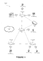
- FIG. 1 shows a block diagram example of a network 1 in accordance with one or more embodiments.
- Network 1 is a digital system that may include a plurality of digital devices such as controller 10 , access points 20 1 - 20 4 and one or more client devices 30 1 - 30 7 .
- the client devices 30 may include any set of devices that communicate wirelessly with access points 20 within network 1 .
- network 1 may include more or less devices than the devices illustrated in FIG. 1 , which may be connected to other devices within network 1 via wired and/or wireless mediums.
- client devices 30 are digital devices that include a hardware processor, memory hierarchy, and input/output (I/O) interfaces including a wireless interface such as an IEEE 802.11 wireless interface.
- the wireless interface may be used to communicate with access points 20 and/or controller 10 .
- Client devices 30 may include one or more antennas for establishing one or more concurrent spatial data streams with an access point 20 .
- Client devices 30 may be wireless electronic devices capable of receiving video, voice, and/or other data streams.
- Such wireless electronic devices may include, but are not limited to, personal computers, laptop computers, netbook computers, wireless music players, portable telephone communication devices, smart phones, tablets, digital televisions, etc.
- Access points 20 1 - 20 4 may be any devices that can associate with client devices 30 to transmit and receive data over wireless channels 35 .
- access points 20 may correspond to a network device such as a wired access port, a wireless access port, a switch, a router, or any combination thereof.
- access point 20 1 may be a router or any device that may be configured as a hotspot (e.g., a cell phone, a tablet, a laptop, etc.).
- Access points 20 may be communicatively coupled to other networks, such as external network 40 , via a transmission medium to send and receive data.
- the data may include, for example, video data and/or voice data.
- the transmission medium may be a wired or a wireless connection.
- Access points 20 communicatively couple client devices 30 to other client devices 30 or other networks (e.g., external network 40 ) by forwarding data to or from client devices 30 .
- FIG. 2 shows a block diagram example of an access point 20 in accordance with one or more embodiments.
- each access point 20 may be a combination of hardware, software, and/or firmware that is configured to configure at least (1) channel widths between associated client devices 30 , and (2) beamforming characteristics for transmission to client devices 30 .
- the access points 20 may be configured by logic on the access points 20 themselves.
- a virtual controller on one or more access points 20 may perform configuration operations as described herein. In one embodiment as shown in FIG.
- an access point 20 may be a network device that comprises one or more of: a hardware processor 21 , data storage 22 , an I/O interface 23 , and device configuration logic 24 .
- Other access points 20 within system 1 may be configured similarly or differently than the access point 20 shown in FIG. 2 .
- Data storage 22 of access point 20 may include a fast read-write memory for storing programs and data during access point 20 's operations and a hierarchy of persistent memory, such as Read Only Memory (ROM), Erasable Programmable Read Only Memory (EPROM,) and/or Flash memory for example, for storing instructions and data needed for the startup and/or operations of access point 20 .
- Data storage 22 stores data that is to be transmitted from access point 20 or data that is received by access point 20 .
- data storage 22 is a distributed set of data storage components.
- I/O interface 23 corresponds to one or more components used for communicating with other devices (e.g., client devices 30 ) via wired or wireless signals.
- I/O interface 23 may include a wired network interface such as an IEEE 802.3 Ethernet interface and/or a wireless interface such as an IEEE 802.11 WLAN interface.
- I/O interface 23 may communicate with client devices 30 over corresponding wireless channels 35 .
- Wireless channels 35 may be of various widths, which may be dynamically changed during operation. For example, each wireless channel 35 may be dynamically configured to operate at 20 MHz, 40 MHz, 80 MHz, or 160 MHz.
- I/O interface 23 may include one or more antennas 25 for communicating with client devices 30 , controller 10 , and other wireless devices in network 1 .
- multiple antennas 25 may be used for forming transmission beams to client devices 30 through adjustment of gain and phase values for corresponding antenna 25 transmissions. The generated beams may avoid objects and create an unobstructed path to client devices 30 to possibly increase transmission capacity.
- Hardware processor 21 is coupled to data storage 22 and I/O interface 23 .
- Hardware processor 21 may be any processing device including, but not limited to a MIPS/ARM-class processor, a microprocessor, a digital signal processor, an application specific integrated circuit, a microcontroller, a state machine, or any type of programmable logic array.
- device configuration logic 24 includes one or more functional units implemented using firmware, hardware, software, or a combination thereof for configuring parameters associated with access point 20 and client devices 30 .
- device configuration logic 24 is shown as implemented on access point 20 , one or more physical or functional components of device configuration logic 24 may be implemented on separate devices.
- the device configuration logic 24 may be configured to adjust (1) channel widths between access points 20 and client devices 30 , and/or (2) beamforming characteristics between access points 20 and clients 30 as will be described in further detail below.
- Controller 10 may be any device that can manage and configure access points 20 and/or client devices 30 operating in network 1 .
- controller 10 may configure one or more access points 20 to (1) adjust channel widths between an access point 20 and client devices 30 and/or (2) steer a client device 30 to an access point 20 that may provide increased capacity through the use of transmission beamforming.
- controller 10 may correspond to a network device such as a wired access port, a wireless access port, a switch, a router, an access point, or any combination thereof.
- controller 10 may be an access point 20 as described above in relation to FIG. 2 .
- controller may utilize beamforming capabilities of access points to increase capacity of wireless channels. For example, in some cases intelligently aiming a data transmission at a receiving client device to avoid obstructions in a wireless channel path may result in an increased data throughput for the wireless channel. The increased capacity of these channels may improve a high density condition or prevent a high density condition from occurring. In some cases, (1) a particular access point may provide a greater capacity gain than other access points in a wireless network, or (2) beamforming may not provide any capacity gain in comparison to traditional communications.
- FIG. 3 shows a method 70 for steering client devices 30 to access points 20 that may increase capacity of an associated wireless channel 35 .
- Method 70 may be performed by controller 10 and/or on one or more access points 20 in network 1 .
- method 70 is only performed for access points 20 and client devices 30 that support beamforming operations (e.g., IEEE 802.11 ac compliant components). In this embodiment, non-beamforming access points 20 and client devices 30 may be ignored in the method 70 .
- beamforming operations e.g., IEEE 802.11 ac compliant components
- Method 70 may begin at operation 71 with the detection of a triggering event.
- the triggering event may be the detection of a high density condition on an access point 20 .
- a high density condition may be defined as the average airtime on a particular access point 20 being greater than a predefined threshold value (e.g., 80% airtime usage).
- a predefined threshold value e.g., 80% airtime usage.
- other triggers may be used.
- method 70 may commence upon the selection of a reset of network 1 or an access point 20 by a network administrator or a client device 30 joining network 1 .
- client devices 30 are matched with candidate access points 20 that share similar capabilities. For example, operation 72 may determine that client device 30 1 supports 20/40/80/160 MHz channel widths and beamforming transmissions. Based on these determined capabilities, operation 72 matches one or more candidate access points 20 for each client device 30 that share similar capabilities (i.e., support 20/40/80/160 MHz channel widths and beamforming transmissions). In one embodiment, client devices 30 that are capable of receiving beamformed signals may be matched with candidate access points 20 that are capable of beamforming transmissions. For example, access points 20 and client devices 30 that support IEEE 802.11ac may be matched together such that beamforming transmissions may be performed when capacity gains may be achieved as described further below.
- matching of client devices 30 with one or more candidate access points 20 may be performed based on results from probe and association sequences.
- operation 72 may match client devices 30 with access points 20 based on support for very high throughput (VHT) and/or high throughput (HT) communications.
- VHT very high throughput
- HT high throughput
- client devices 30 that support VHT communications may be matched with one or more candidate access points 20 that also support VHT communications.
- client devices 30 that support HT communications may be matched with candidate access points 20 that also support HT communications. This matching of client devices 30 and access points 20 that share similar capabilities will improve potential capacity gains by reducing the likelihood of data transfer bottlenecks.
- wireless channels 35 between each client device 30 and corresponding candidate access points 20 are examined and characterized/tested.
- operation 73 determines the impulse response H or channel state information (CSI) of the wireless channels 35 between each client device 30 and corresponding candidate access points 20 . Characterization or testing of each wireless channel 35 may be performed using explicit or implicit feedback mechanisms.
- CSI channel state information
- explicit feedback is used to characterize wireless channels 35 between access points 20 and their associated client devices 30 using a sounding mechanism.
- each client device 30 may send explicit feedback in response to corresponding requests from each access point 20 .
- the request from access points 20 may be Request-To-Send (RTS) and/or Network Discovery Protocol Announcement (NDPA) frames.
- RTS Request-To-Send
- NDPA Network Discovery Protocol Announcement
- each access point 20 may send a RTS in a control wrapper frame (cwRTS) to each associated client device 30 .
- the cwRTS may include an NDPA indicator and a set of training symbols to solicit information from associated client devices 30 .
- each client device 30 transmits a Clear-To-Send (CTS) in a control wrapper frame (cwCTS) to corresponding access points 20 .
- Access points 20 may calculate CSI estimates for wireless channels 35 based on responses from client devices 30 .
- the CSI estimates describe how a signal propagates from access points 20 to client devices 30 over wireless channels 35 and represent the combined effect of, for example, scattering, fading, and power decay with distance over wireless channels 35 .
- these CSI estimates makes it possible to determine the potential capacity increases using beamforming transmissions between each access point 20 and associated client devices 30 in network 1 .
- CSI estimates are obtained for wireless channels 35 between access points 20 and their associated client devices 30 .
- An access point 20 's associated client devices 30 are client devices 30 that for at least a momentary period of time are wirelessly connected with the respective access point 20 .
- controller 10 may cause each client device 30 to associate with candidate access points 20 that are viewable/in-range for a brief period of time (e.g., 1-2 seconds) such that operation 73 may establish CSI estimates for corresponding wireless channels 35 between each client device 30 and each corresponding in-range candidate access point 20 .
- controller 10 may determine CSI estimates for wireless channels 35 between candidate access points 20 and non-associated client devices 30 by spoofing CSI requests. For example, controller 10 may cause access point 20 1 to spoof a CSI estimation request frame with the source address of access point 20 2 . Access point 20 1 transmits the request to client device 30 4 that is associated with access point 20 2 , but not with access point 20 1 . Upon receipt of the request, client device 30 4 transmits the response to access point 20 2 , based on the spoofed source address in the request. The CSI estimate computed by access point 20 2 represents the wireless channel 35 between access point 20 1 and the non-associated client device 30 4 . Controller 10 may retrieve this CSI estimate for further processing. By spoofing the source address, this routine does not require each client device 30 to be associated with each access point 20 in network 10 such that CSI estimations may be determined for each possible wireless channel 35 .
- CSI estimates may also be determined based on implicit feedback. Implicit feedback is obtained from information transmitted by client devices 30 upon association with access points 20 . In particular, client devices 30 may transmit implicit long symbols generated on client devices 30 to access points 20 . Access points 20 may thereafter generate CSI estimates based on these long symbols. Explicit feedback has the benefit of allowing access points 20 determine CSI estimates based on their transmission view to client devices 30 , whereas implicit feedback is sourced from client devices 30 alone.
- operation 74 tests each connection/wireless channel 35 to estimate potential capacity gains achieved through the association of each client device 30 with each corresponding candidate access point 20 using beamforming transmissions based on the previously computed CSI estimates.
- Beamforming transmissions apply weights to transmitted signals to improve reception at client devices 30 .
- the weights are calculated based on CSI estimates and compensate for interferences in wireless channels 35 .
- testing each connection/wireless channel 35 to estimate potential capacity gains may be based on one or more of wireless signal strength for each connection/wireless channel 35 and the number of spatial streams for the connection/wireless channel 35 .
- Equation 1 matrix X represents the data transmitted from an access point 20 to a client device 30 ; k represents the signal to noise ratio in the transmission; H represents the channel fading matrix (i.e., the impulse response/CSI for the wireless channel 35 ); Z represents additive noise in the wireless channel 35 ; V represents a transmit weighting matrix used to create the transmission beam from the access point 20 to the receiving client device 30 ; and matrix Y represents the received signal.
- the singular value decomposition of the channel fading matrix H is used to calculate the weights in transmit weighting matrix V.
- Equation 2 V* is the complex conjugate transpose of transmit weighting matrix V; S is a diagonal matrix of singular values, which are the square roots of the eigenvalues of H ⁇ H*; and U is the unitary matrix.
- SNR( r ) SNR(avg) ⁇ S ( r )* S ( r ) Equation 3
- Equation 3 S(r) is the r'th diagonal entry of spatial stream S.
- operation 74 may use a metric C to evaluate the potential capacity benefit for using transmission beamforming between each client device 30 and corresponding candidate access points 20 in network 1 using the determined CSI information obtained at operation 73 .
- the metric C over each of the N spatial streams may be represented as:
- B represents the channel width for the corresponding wireless channel 35 .
- the metric C may be calculated for each client device 30 in network 1 in relation to each corresponding candidate access point 20 . In some embodiments values for metric C are calculated only for client devices 30 and corresponding candidate access points 20 that are capable of beamforming signals (e.g., only 802.11ac access points 20 and client devices 30 ).
- operation 75 compares each of the C values for each client device 30 with a capacity threshold value and determines (1) whether beamforming transmissions provides a capacity benefit and (2) for each client device 30 , which corresponding candidate access point 20 provides the greatest beamforming capacity gain.
- beamforming transmissions provide capacity gains when corresponding metric C values fall below a capacity threshold value.
- the capacity threshold is equal to the channel width of the corresponding wireless channel 35 (e.g., 20 MHz, 40 MHz, 80 MHz, or 160 MHz). For example, client device 30 1 in FIG.
- operation 75 may determine that client device 30 1 obtains capacity gains above the capacity threshold (i.e., C>80 MHz) when associated with access points 20 3 and 20 4 with transmission beamforming activated. Since the capacity gain would be higher when associated with access point 20 4 , operation 75 determines that client device 30 1 should be associated with access point 20 4 . Operation 75 may be performed for each client device 30 such that each client device 30 is associated with an access point 30 that potentially delivers a higher throughput capacity.
- operation 75 may determine that no change in association for a client device 30 may be needed as metric C values for the client device 30 do not exceed the capacity threshold value (e.g., C ⁇ 80 MHz for each access point 20 ). Based on the determination regarding beamforming transmission, operation 75 associates a client device 30 with an appropriate access point 20 that delivers the highest capacity gain with beamforming or maintains the client device 30 with the current access point 20 without beamforming activated. Moreover, a bin packing based approach could also be adopted to solve the problem of associating a respective client device with an appropriate access point, because the number of client devices to which an access point can beamform is usually limited.
- the capacity threshold value e.g., C ⁇ 80 MHz for each access point 20
- operation 75 may determine an optimized association of client devices 30 that maximizes capacity of the entire network 1 .
- operation 75 may associate each of D client devices 30 with access points 20 such that the sum of all C values is maximized over the network 1 .
- maximization of the capacity of network 1 may be viewed as a bin packing problem, where different associations of client devices 30 with access points 20 using beamforming transmissions are proposed and corresponding C values for the network are computed.
- the permutation with the highest capacity C for network 1 may be selected.
- method 70 improves transmission capacity of network 1 in an intelligent manner.
- method 70 may be combined with channel width configuration methods disclosed in co-pending patent application entitled “Channel Width Configuration Based on Network Condition” to improve performance and efficiency of network 1 by (1) adjusting channel widths between access points 20 and client devices 30 and (2) steering client devices 30 to access points 20 that may increase capacity of an associated wireless channel 35 .
- An embodiment of the invention may be an article of manufacture in which a machine-readable medium (such as microelectronic memory) has stored thereon instructions which program one or more data processing components (generically referred to here as a “processor”) to perform the operations described above.
- a machine-readable medium such as microelectronic memory
- data processing components program one or more data processing components (generically referred to here as a “processor”) to perform the operations described above.
- some of these operations might be performed by specific hardware components that contain hardwired logic (e.g., dedicated digital filter blocks and state machines). Those operations might alternatively be performed by any combination of programmed data processing components and fixed hardwired circuit components.
- the discussion focuses on uplink medium control with respect to frame aggregation, it is contemplated that control of other types of messages are applicable.
Abstract
Description
Y=k×H×V×X+
H=U×S×V* Equation 2
SNR(r)=SNR(avg)×S(r)*S(r) Equation 3
SNR=min(SNR(r))
Claims (21)
Priority Applications (1)
| Application Number | Priority Date | Filing Date | Title |
|---|---|---|---|
| US13/857,314 US9503915B2 (en) | 2013-03-15 | 2013-04-05 | Dynamic beamforming configuration based on network conditions |
Applications Claiming Priority (2)
| Application Number | Priority Date | Filing Date | Title |
|---|---|---|---|
| US201361793179P | 2013-03-15 | 2013-03-15 | |
| US13/857,314 US9503915B2 (en) | 2013-03-15 | 2013-04-05 | Dynamic beamforming configuration based on network conditions |
Publications (2)
| Publication Number | Publication Date |
|---|---|
| US20140269370A1 US20140269370A1 (en) | 2014-09-18 |
| US9503915B2 true US9503915B2 (en) | 2016-11-22 |
Family
ID=51526606
Family Applications (2)
| Application Number | Title | Priority Date | Filing Date |
|---|---|---|---|
| US13/857,321 Active 2033-04-22 US9467873B2 (en) | 2013-03-15 | 2013-04-05 | Channel width configuration based on network conditions |
| US13/857,314 Active 2033-08-11 US9503915B2 (en) | 2013-03-15 | 2013-04-05 | Dynamic beamforming configuration based on network conditions |
Family Applications Before (1)
| Application Number | Title | Priority Date | Filing Date |
|---|---|---|---|
| US13/857,321 Active 2033-04-22 US9467873B2 (en) | 2013-03-15 | 2013-04-05 | Channel width configuration based on network conditions |
Country Status (1)
| Country | Link |
|---|---|
| US (2) | US9467873B2 (en) |
Cited By (1)
| Publication number | Priority date | Publication date | Assignee | Title |
|---|---|---|---|---|
| US10285176B1 (en) | 2017-04-28 | 2019-05-07 | Sprint Communications Company L.P. | Wireless access point optimization of carrier aggregation using beamforming |
Families Citing this family (16)
| Publication number | Priority date | Publication date | Assignee | Title |
|---|---|---|---|---|
| US9467873B2 (en) | 2013-03-15 | 2016-10-11 | Aruba Networks, Inc. | Channel width configuration based on network conditions |
| US9591562B2 (en) * | 2013-10-31 | 2017-03-07 | Aruba Networks, Inc. | Provisioning access point bandwidth based on predetermined events |
| US10070378B2 (en) * | 2014-02-07 | 2018-09-04 | Fortinet, Inc. | Steering inherently autonomous wireless devices to access points based on MIMO (multiple input/ multiple output) capabilities of network components |
| US9661497B2 (en) * | 2014-08-28 | 2017-05-23 | Cisco Technology, Inc. | Control and enhancement of direct wireless service communications |
| US10333821B2 (en) | 2014-11-25 | 2019-06-25 | Vmware, Inc. | Method and system for optimizing network traffic in a distributed system with a point of convergence |
| US10608955B2 (en) | 2014-11-25 | 2020-03-31 | Vmware, Inc. | Reverse breadth-first search method for optimizing network traffic in a distributed system with a point of convergence |
| US9641452B2 (en) * | 2014-11-25 | 2017-05-02 | Vmware, Inc. | Resolving a convex optimization problem to optimize network traffic in a distributed system |
| US9673874B2 (en) * | 2015-04-27 | 2017-06-06 | Aruba Networks, Inc. | System and method for controlling selection of network devices for beamforming |
| CN105101355B (en) * | 2015-08-24 | 2018-07-03 | 合肥工业大学 | A kind of access point selection method based on user throughput estimation in wlan system |
| EP3284279B1 (en) | 2015-09-29 | 2020-10-28 | Hewlett-Packard Enterprise Development LP | Air-time capacities |
| US10271220B2 (en) * | 2016-02-12 | 2019-04-23 | Microsoft Technology Licensing, Llc | Wireless communication using a central controller |
| US20170289900A1 (en) * | 2016-04-01 | 2017-10-05 | Izoslav Tchigevsky | Adaptive access point resource management |
| US10972943B2 (en) * | 2019-03-08 | 2021-04-06 | Cisco Technology, Inc. | Smart channel selection for low bandwidth IoT clients |
| US11438835B2 (en) * | 2019-05-31 | 2022-09-06 | Hewlett Packard Enterprise Development Lp | Determining when to adjust a power state of access points |
| US11363527B2 (en) * | 2019-05-31 | 2022-06-14 | Hewlett Packard Enterprise Development Lp | Adjusting power states of access points |
| CN115699605A (en) * | 2020-05-26 | 2023-02-03 | 艾斯康实验室公司 | Interference aware beamforming |
Citations (23)
| Publication number | Priority date | Publication date | Assignee | Title |
|---|---|---|---|---|
| US20030087629A1 (en) * | 2001-09-28 | 2003-05-08 | Bluesocket, Inc. | Method and system for managing data traffic in wireless networks |
| US20060020700A1 (en) | 2002-05-13 | 2006-01-26 | Microsoft Corporation | Adaptive allocation of last-hop bandwidth based on monitoring of end-to-end throughput |
| US20060233131A1 (en) * | 2005-04-19 | 2006-10-19 | Qualcomm Incorporated | Channel quality reporting for adaptive sectorization |
| US20080080553A1 (en) * | 2006-09-29 | 2008-04-03 | Motorola, Inc. | Transmission channel bandwidth selection for communications between multi-bandwidth nodes |
| US20090290518A1 (en) * | 2008-05-22 | 2009-11-26 | Motorola, Inc. | Method for facilitating sharing of channel information in a wireless communication network |
| US20100085884A1 (en) * | 2008-09-30 | 2010-04-08 | Murari Srinivasan | Dynamic topological adaptation |
| US20100202548A1 (en) * | 2009-02-12 | 2010-08-12 | Futurewei Technologies, Inc. | System and Method for Wireless Communications Using Spatial Multiplexing with Incomplete Channel Information |
| US20110158190A1 (en) * | 2009-12-09 | 2011-06-30 | Mikio Kuwahara | Cellular radio communication system, radio base station apparatus and radio terminal unit |
| US20110188393A1 (en) * | 2010-01-29 | 2011-08-04 | Qualcomm Incorporated | Reporting of channel information to support coordinated multi-point data transmission |
| US20120039265A1 (en) * | 2010-02-12 | 2012-02-16 | Qualcomm Incorporated | Controlling access point transmit power based on received access terminal messages |
| US8150399B2 (en) * | 2007-12-21 | 2012-04-03 | Intel Corporation | Techniques for wireless communications networks employing beamforming |
| US20120170471A1 (en) * | 2010-12-31 | 2012-07-05 | Openpeak Inc. | Automated access point selection to provide communication network presence to a communication device |
| US8345732B2 (en) * | 2005-06-28 | 2013-01-01 | Broadcom Corporation | Feedback of channel information in a closed loop beamforming wireless communication system |
| US20130097309A1 (en) | 2010-05-04 | 2013-04-18 | Azuki Systems, Inc. | Method and apparatus for carrier controlled dynamic rate adaptation and client playout rate reduction |
| US20130136016A1 (en) * | 2011-10-13 | 2013-05-30 | Electronics And Telecommunications Research Institute | Method and apparatus of peer link setting, and method and apparatus of channel switching, in wireless mesh network |
| US20130176979A1 (en) * | 2010-09-13 | 2013-07-11 | Ntt Docomo Inc. | Radio communication control method, radio communication system, radio base station, and mobile terminal |
| US8509071B1 (en) | 2010-10-06 | 2013-08-13 | Juniper Networks, Inc. | Multi-dimensional traffic management |
| US20130229307A1 (en) * | 2012-03-02 | 2013-09-05 | Samsung Electronics Co. Ltd. | Apparatus and method for controlling adaptive beamforming gain in wireless communication system |
| US20140025796A1 (en) | 2012-07-19 | 2014-01-23 | Commvault Systems, Inc. | Automated grouping of computing devices in a networked data storage system |
| US20140059265A1 (en) | 2012-08-23 | 2014-02-27 | Dell Products, Lp | Fabric Independent PCIe Cluster Manager |
| US20140094164A1 (en) * | 2012-09-28 | 2014-04-03 | Qualcomm Incorporated | Iterative coordinated beamforming systems and methods |
| US8787841B2 (en) * | 2006-06-27 | 2014-07-22 | Qualcomm Incorporated | Method and system for providing beamforming feedback in wireless communication systems |
| US20140269280A1 (en) | 2013-03-15 | 2014-09-18 | Aruba Networks, Inc. | Channel Width Configuration Based on Network Conditions |
Family Cites Families (1)
| Publication number | Priority date | Publication date | Assignee | Title |
|---|---|---|---|---|
| US20130100955A1 (en) * | 2011-10-24 | 2013-04-25 | Qualcomm Incorporated | Technique for prioritizing traffic at a router |
-
2013
- 2013-04-05 US US13/857,321 patent/US9467873B2/en active Active
- 2013-04-05 US US13/857,314 patent/US9503915B2/en active Active
Patent Citations (23)
| Publication number | Priority date | Publication date | Assignee | Title |
|---|---|---|---|---|
| US20030087629A1 (en) * | 2001-09-28 | 2003-05-08 | Bluesocket, Inc. | Method and system for managing data traffic in wireless networks |
| US20060020700A1 (en) | 2002-05-13 | 2006-01-26 | Microsoft Corporation | Adaptive allocation of last-hop bandwidth based on monitoring of end-to-end throughput |
| US20060233131A1 (en) * | 2005-04-19 | 2006-10-19 | Qualcomm Incorporated | Channel quality reporting for adaptive sectorization |
| US8345732B2 (en) * | 2005-06-28 | 2013-01-01 | Broadcom Corporation | Feedback of channel information in a closed loop beamforming wireless communication system |
| US8787841B2 (en) * | 2006-06-27 | 2014-07-22 | Qualcomm Incorporated | Method and system for providing beamforming feedback in wireless communication systems |
| US20080080553A1 (en) * | 2006-09-29 | 2008-04-03 | Motorola, Inc. | Transmission channel bandwidth selection for communications between multi-bandwidth nodes |
| US8150399B2 (en) * | 2007-12-21 | 2012-04-03 | Intel Corporation | Techniques for wireless communications networks employing beamforming |
| US20090290518A1 (en) * | 2008-05-22 | 2009-11-26 | Motorola, Inc. | Method for facilitating sharing of channel information in a wireless communication network |
| US20100085884A1 (en) * | 2008-09-30 | 2010-04-08 | Murari Srinivasan | Dynamic topological adaptation |
| US20100202548A1 (en) * | 2009-02-12 | 2010-08-12 | Futurewei Technologies, Inc. | System and Method for Wireless Communications Using Spatial Multiplexing with Incomplete Channel Information |
| US20110158190A1 (en) * | 2009-12-09 | 2011-06-30 | Mikio Kuwahara | Cellular radio communication system, radio base station apparatus and radio terminal unit |
| US20110188393A1 (en) * | 2010-01-29 | 2011-08-04 | Qualcomm Incorporated | Reporting of channel information to support coordinated multi-point data transmission |
| US20120039265A1 (en) * | 2010-02-12 | 2012-02-16 | Qualcomm Incorporated | Controlling access point transmit power based on received access terminal messages |
| US20130097309A1 (en) | 2010-05-04 | 2013-04-18 | Azuki Systems, Inc. | Method and apparatus for carrier controlled dynamic rate adaptation and client playout rate reduction |
| US20130176979A1 (en) * | 2010-09-13 | 2013-07-11 | Ntt Docomo Inc. | Radio communication control method, radio communication system, radio base station, and mobile terminal |
| US8509071B1 (en) | 2010-10-06 | 2013-08-13 | Juniper Networks, Inc. | Multi-dimensional traffic management |
| US20120170471A1 (en) * | 2010-12-31 | 2012-07-05 | Openpeak Inc. | Automated access point selection to provide communication network presence to a communication device |
| US20130136016A1 (en) * | 2011-10-13 | 2013-05-30 | Electronics And Telecommunications Research Institute | Method and apparatus of peer link setting, and method and apparatus of channel switching, in wireless mesh network |
| US20130229307A1 (en) * | 2012-03-02 | 2013-09-05 | Samsung Electronics Co. Ltd. | Apparatus and method for controlling adaptive beamforming gain in wireless communication system |
| US20140025796A1 (en) | 2012-07-19 | 2014-01-23 | Commvault Systems, Inc. | Automated grouping of computing devices in a networked data storage system |
| US20140059265A1 (en) | 2012-08-23 | 2014-02-27 | Dell Products, Lp | Fabric Independent PCIe Cluster Manager |
| US20140094164A1 (en) * | 2012-09-28 | 2014-04-03 | Qualcomm Incorporated | Iterative coordinated beamforming systems and methods |
| US20140269280A1 (en) | 2013-03-15 | 2014-09-18 | Aruba Networks, Inc. | Channel Width Configuration Based on Network Conditions |
Cited By (1)
| Publication number | Priority date | Publication date | Assignee | Title |
|---|---|---|---|---|
| US10285176B1 (en) | 2017-04-28 | 2019-05-07 | Sprint Communications Company L.P. | Wireless access point optimization of carrier aggregation using beamforming |
Also Published As
| Publication number | Publication date |
|---|---|
| US20140269370A1 (en) | 2014-09-18 |
| US20140269280A1 (en) | 2014-09-18 |
| US9467873B2 (en) | 2016-10-11 |
Similar Documents
| Publication | Publication Date | Title |
|---|---|---|
| US9503915B2 (en) | Dynamic beamforming configuration based on network conditions | |
| JP7062597B2 (en) | Channel covariance feedback for enhanced FD-MIMO | |
| US10020577B2 (en) | Technique for detection of line-of-sight transmissions using millimeter wave communication devices | |
| KR102088529B1 (en) | Method and apparatus for beam training in communication system | |
| US9753118B2 (en) | Technique for obtaining the rotation of a wireless device | |
| US9590707B1 (en) | Using compressed beamforming information for optimizing multiple-input multiple-output operations | |
| US10257836B1 (en) | Joint procedure for beam management and partial control beam failure recovery | |
| JP5571252B2 (en) | Device, system and method for coordinating channel utilization for wireless transmission | |
| KR101414665B1 (en) | Multilayer beamforming with partial channel state information | |
| TWI540857B (en) | Methods for controlling antennas and apparatuses using the same | |
| EP3360263A1 (en) | Techniques to reduce radiated power for mimo wireless systems | |
| US20230412291A1 (en) | Non-Line-of-Sight Detection | |
| US10466345B1 (en) | Time-of-arrival estimation with subspace methods | |
| US20220217567A1 (en) | Channel measurement method and communications apparatus | |
| WO2016041166A1 (en) | Scheme of finite power transmission statuses for low cost wireless broadband communication system | |
| US20150117322A1 (en) | Policy-Based Control Mechanism For Wireless Network Physical Layer Resources | |
| US20170005708A1 (en) | Sta assisted dynamic sounding in multiuser beamforming | |
| US9954642B2 (en) | Spatial contention in dense wireless network | |
| US20220123816A1 (en) | Method and apparatus for beamspace processing based on multiple beamspace bases | |
| US20220191853A1 (en) | Identifying a beam in 5g wireless communication systems | |
| US20200052749A1 (en) | Precoding matrix indicator determination in wireless communication systems | |
| US9521558B2 (en) | Computing system with coordination mechanism and method of operation thereof | |
| US20230141814A1 (en) | Apparatus and method for multi-link-based wireless communication | |
| CN113412585B (en) | Method and device for carrying out beam space processing based on multiple beam space bases | |
| WO2016011651A1 (en) | Information transmission method and device, base station and user equipment |
Legal Events
| Date | Code | Title | Description |
|---|---|---|---|
| AS | Assignment |
Owner name: ARUBA NETWORKS, INC., CALIFORNIA Free format text: ASSIGNMENT OF ASSIGNORS INTEREST;ASSIGNORS:DHARANIPRAGADA, KALYAN;BHANAGE, GUATAM D.;KANNAN, VENKATESH;AND OTHERS;SIGNING DATES FROM 20130401 TO 20130408;REEL/FRAME:030289/0004 |
|
| AS | Assignment |
Owner name: HEWLETT-PACKARD DEVELOPMENT COMPANY, L.P., TEXAS Free format text: ASSIGNMENT OF ASSIGNORS INTEREST;ASSIGNOR:ARUBA NETWORKS, INC.;REEL/FRAME:035814/0518 Effective date: 20150529 |
|
| AS | Assignment |
Owner name: ARUBA NETWORKS, INC., CALIFORNIA Free format text: ASSIGNMENT OF ASSIGNORS INTEREST;ASSIGNOR:HEWLETT-PACKARD DEVELOPMENT COMPANY, L.P.;REEL/FRAME:036379/0274 Effective date: 20150807 |
|
| STCF | Information on status: patent grant |
Free format text: PATENTED CASE |
|
| AS | Assignment |
Owner name: HEWLETT PACKARD ENTERPRISE DEVELOPMENT LP, TEXAS Free format text: ASSIGNMENT OF ASSIGNORS INTEREST;ASSIGNOR:ARUBA NETWORKS, INC.;REEL/FRAME:045921/0055 Effective date: 20171115 |
|
| MAFP | Maintenance fee payment |
Free format text: PAYMENT OF MAINTENANCE FEE, 4TH YEAR, LARGE ENTITY (ORIGINAL EVENT CODE: M1551); ENTITY STATUS OF PATENT OWNER: LARGE ENTITY Year of fee payment: 4 |