US9501204B2 - Display device - Google Patents
Display device Download PDFInfo
- Publication number
- US9501204B2 US9501204B2 US15/001,191 US201615001191A US9501204B2 US 9501204 B2 US9501204 B2 US 9501204B2 US 201615001191 A US201615001191 A US 201615001191A US 9501204 B2 US9501204 B2 US 9501204B2
- Authority
- US
- United States
- Prior art keywords
- dimensional object
- display
- control unit
- change
- dimensional
- Prior art date
- Legal status (The legal status is an assumption and is not a legal conclusion. Google has not performed a legal analysis and makes no representation as to the accuracy of the status listed.)
- Active
Links
- 230000008859 change Effects 0.000 claims description 59
- 238000003384 imaging method Methods 0.000 claims description 26
- 238000001514 detection method Methods 0.000 claims description 24
- 239000007788 liquid Substances 0.000 claims description 7
- 239000004033 plastic Substances 0.000 claims description 2
- 238000000034 method Methods 0.000 description 56
- 230000008569 process Effects 0.000 description 31
- 230000009471 action Effects 0.000 description 26
- 238000010586 diagram Methods 0.000 description 25
- 238000004891 communication Methods 0.000 description 14
- 239000004927 clay Substances 0.000 description 10
- 239000000463 material Substances 0.000 description 10
- 230000006870 function Effects 0.000 description 9
- 238000006073 displacement reaction Methods 0.000 description 3
- XLYOFNOQVPJJNP-UHFFFAOYSA-N water Substances O XLYOFNOQVPJJNP-UHFFFAOYSA-N 0.000 description 3
- 230000001133 acceleration Effects 0.000 description 2
- 238000012217 deletion Methods 0.000 description 2
- 230000037430 deletion Effects 0.000 description 2
- 238000007667 floating Methods 0.000 description 2
- 238000012545 processing Methods 0.000 description 2
- 230000035945 sensitivity Effects 0.000 description 2
- 230000000007 visual effect Effects 0.000 description 2
- XEEYBQQBJWHFJM-UHFFFAOYSA-N Iron Chemical compound [Fe] XEEYBQQBJWHFJM-UHFFFAOYSA-N 0.000 description 1
- 230000003190 augmentative effect Effects 0.000 description 1
- 230000000295 complement effect Effects 0.000 description 1
- 230000003247 decreasing effect Effects 0.000 description 1
- 230000005611 electricity Effects 0.000 description 1
- 238000005401 electroluminescence Methods 0.000 description 1
- 238000005516 engineering process Methods 0.000 description 1
- 238000002474 experimental method Methods 0.000 description 1
- 239000011521 glass Substances 0.000 description 1
- 239000004973 liquid crystal related substance Substances 0.000 description 1
- 239000007769 metal material Substances 0.000 description 1
- 229910044991 metal oxide Inorganic materials 0.000 description 1
- 150000004706 metal oxides Chemical class 0.000 description 1
- 230000003287 optical effect Effects 0.000 description 1
- 238000005293 physical law Methods 0.000 description 1
- 230000009467 reduction Effects 0.000 description 1
- 239000004576 sand Substances 0.000 description 1
- 239000004065 semiconductor Substances 0.000 description 1
- 239000000779 smoke Substances 0.000 description 1
- 238000002791 soaking Methods 0.000 description 1
- 230000007480 spreading Effects 0.000 description 1
- 230000003068 static effect Effects 0.000 description 1
- 230000001960 triggered effect Effects 0.000 description 1
Images


Classifications
-
- G—PHYSICS
- G06—COMPUTING; CALCULATING OR COUNTING
- G06F—ELECTRIC DIGITAL DATA PROCESSING
- G06F3/00—Input arrangements for transferring data to be processed into a form capable of being handled by the computer; Output arrangements for transferring data from processing unit to output unit, e.g. interface arrangements
- G06F3/01—Input arrangements or combined input and output arrangements for interaction between user and computer
- G06F3/048—Interaction techniques based on graphical user interfaces [GUI]
- G06F3/0481—Interaction techniques based on graphical user interfaces [GUI] based on specific properties of the displayed interaction object or a metaphor-based environment, e.g. interaction with desktop elements like windows or icons, or assisted by a cursor's changing behaviour or appearance
- G06F3/04815—Interaction with a metaphor-based environment or interaction object displayed as three-dimensional, e.g. changing the user viewpoint with respect to the environment or object
-
- G—PHYSICS
- G06—COMPUTING; CALCULATING OR COUNTING
- G06F—ELECTRIC DIGITAL DATA PROCESSING
- G06F1/00—Details not covered by groups G06F3/00 - G06F13/00 and G06F21/00
- G06F1/16—Constructional details or arrangements
- G06F1/1613—Constructional details or arrangements for portable computers
- G06F1/1633—Constructional details or arrangements of portable computers not specific to the type of enclosures covered by groups G06F1/1615 - G06F1/1626
- G06F1/1684—Constructional details or arrangements related to integrated I/O peripherals not covered by groups G06F1/1635 - G06F1/1675
- G06F1/1686—Constructional details or arrangements related to integrated I/O peripherals not covered by groups G06F1/1635 - G06F1/1675 the I/O peripheral being an integrated camera
-
- G—PHYSICS
- G06—COMPUTING; CALCULATING OR COUNTING
- G06F—ELECTRIC DIGITAL DATA PROCESSING
- G06F3/00—Input arrangements for transferring data to be processed into a form capable of being handled by the computer; Output arrangements for transferring data from processing unit to output unit, e.g. interface arrangements
- G06F3/01—Input arrangements or combined input and output arrangements for interaction between user and computer
- G06F3/011—Arrangements for interaction with the human body, e.g. for user immersion in virtual reality
-
- G—PHYSICS
- G06—COMPUTING; CALCULATING OR COUNTING
- G06F—ELECTRIC DIGITAL DATA PROCESSING
- G06F3/00—Input arrangements for transferring data to be processed into a form capable of being handled by the computer; Output arrangements for transferring data from processing unit to output unit, e.g. interface arrangements
- G06F3/01—Input arrangements or combined input and output arrangements for interaction between user and computer
- G06F3/017—Gesture based interaction, e.g. based on a set of recognized hand gestures
-
- G—PHYSICS
- G06—COMPUTING; CALCULATING OR COUNTING
- G06F—ELECTRIC DIGITAL DATA PROCESSING
- G06F3/00—Input arrangements for transferring data to be processed into a form capable of being handled by the computer; Output arrangements for transferring data from processing unit to output unit, e.g. interface arrangements
- G06F3/01—Input arrangements or combined input and output arrangements for interaction between user and computer
- G06F3/03—Arrangements for converting the position or the displacement of a member into a coded form
- G06F3/0304—Detection arrangements using opto-electronic means
- G06F3/0325—Detection arrangements using opto-electronic means using a plurality of light emitters or reflectors or a plurality of detectors forming a reference frame from which to derive the orientation of the object, e.g. by triangulation or on the basis of reference deformation in the picked up image
-
- G—PHYSICS
- G06—COMPUTING; CALCULATING OR COUNTING
- G06F—ELECTRIC DIGITAL DATA PROCESSING
- G06F3/00—Input arrangements for transferring data to be processed into a form capable of being handled by the computer; Output arrangements for transferring data from processing unit to output unit, e.g. interface arrangements
- G06F3/01—Input arrangements or combined input and output arrangements for interaction between user and computer
- G06F3/03—Arrangements for converting the position or the displacement of a member into a coded form
- G06F3/041—Digitisers, e.g. for touch screens or touch pads, characterised by the transducing means
- G06F3/0416—Control or interface arrangements specially adapted for digitisers
-
- G—PHYSICS
- G06—COMPUTING; CALCULATING OR COUNTING
- G06F—ELECTRIC DIGITAL DATA PROCESSING
- G06F3/00—Input arrangements for transferring data to be processed into a form capable of being handled by the computer; Output arrangements for transferring data from processing unit to output unit, e.g. interface arrangements
- G06F3/01—Input arrangements or combined input and output arrangements for interaction between user and computer
- G06F3/03—Arrangements for converting the position or the displacement of a member into a coded form
- G06F3/041—Digitisers, e.g. for touch screens or touch pads, characterised by the transducing means
- G06F3/044—Digitisers, e.g. for touch screens or touch pads, characterised by the transducing means by capacitive means
-
- G—PHYSICS
- G06—COMPUTING; CALCULATING OR COUNTING
- G06F—ELECTRIC DIGITAL DATA PROCESSING
- G06F3/00—Input arrangements for transferring data to be processed into a form capable of being handled by the computer; Output arrangements for transferring data from processing unit to output unit, e.g. interface arrangements
- G06F3/01—Input arrangements or combined input and output arrangements for interaction between user and computer
- G06F3/048—Interaction techniques based on graphical user interfaces [GUI]
- G06F3/0484—Interaction techniques based on graphical user interfaces [GUI] for the control of specific functions or operations, e.g. selecting or manipulating an object, an image or a displayed text element, setting a parameter value or selecting a range
- G06F3/04845—Interaction techniques based on graphical user interfaces [GUI] for the control of specific functions or operations, e.g. selecting or manipulating an object, an image or a displayed text element, setting a parameter value or selecting a range for image manipulation, e.g. dragging, rotation, expansion or change of colour
-
- G—PHYSICS
- G06—COMPUTING; CALCULATING OR COUNTING
- G06T—IMAGE DATA PROCESSING OR GENERATION, IN GENERAL
- G06T19/00—Manipulating 3D models or images for computer graphics
- G06T19/006—Mixed reality
-
- G—PHYSICS
- G06—COMPUTING; CALCULATING OR COUNTING
- G06T—IMAGE DATA PROCESSING OR GENERATION, IN GENERAL
- G06T19/00—Manipulating 3D models or images for computer graphics
- G06T19/20—Editing of 3D images, e.g. changing shapes or colours, aligning objects or positioning parts
-
- G06T3/18—
-
- G—PHYSICS
- G06—COMPUTING; CALCULATING OR COUNTING
- G06T—IMAGE DATA PROCESSING OR GENERATION, IN GENERAL
- G06T7/00—Image analysis
- G06T7/20—Analysis of motion
- G06T7/285—Analysis of motion using a sequence of stereo image pairs
-
- G—PHYSICS
- G09—EDUCATION; CRYPTOGRAPHY; DISPLAY; ADVERTISING; SEALS
- G09G—ARRANGEMENTS OR CIRCUITS FOR CONTROL OF INDICATING DEVICES USING STATIC MEANS TO PRESENT VARIABLE INFORMATION
- G09G3/00—Control arrangements or circuits, of interest only in connection with visual indicators other than cathode-ray tubes
- G09G3/001—Control arrangements or circuits, of interest only in connection with visual indicators other than cathode-ray tubes using specific devices not provided for in groups G09G3/02 - G09G3/36, e.g. using an intermediate record carrier such as a film slide; Projection systems; Display of non-alphanumerical information, solely or in combination with alphanumerical information, e.g. digital display on projected diapositive as background
- G09G3/003—Control arrangements or circuits, of interest only in connection with visual indicators other than cathode-ray tubes using specific devices not provided for in groups G09G3/02 - G09G3/36, e.g. using an intermediate record carrier such as a film slide; Projection systems; Display of non-alphanumerical information, solely or in combination with alphanumerical information, e.g. digital display on projected diapositive as background to produce spatial visual effects
-
- G—PHYSICS
- G09—EDUCATION; CRYPTOGRAPHY; DISPLAY; ADVERTISING; SEALS
- G09G—ARRANGEMENTS OR CIRCUITS FOR CONTROL OF INDICATING DEVICES USING STATIC MEANS TO PRESENT VARIABLE INFORMATION
- G09G5/00—Control arrangements or circuits for visual indicators common to cathode-ray tube indicators and other visual indicators
- G09G5/08—Cursor circuits
-
- H—ELECTRICITY
- H04—ELECTRIC COMMUNICATION TECHNIQUE
- H04N—PICTORIAL COMMUNICATION, e.g. TELEVISION
- H04N13/00—Stereoscopic video systems; Multi-view video systems; Details thereof
-
- H04N13/0275—
-
- H04N13/0497—
-
- H—ELECTRICITY
- H04—ELECTRIC COMMUNICATION TECHNIQUE
- H04N—PICTORIAL COMMUNICATION, e.g. TELEVISION
- H04N13/00—Stereoscopic video systems; Multi-view video systems; Details thereof
- H04N13/20—Image signal generators
- H04N13/275—Image signal generators from 3D object models, e.g. computer-generated stereoscopic image signals
-
- H—ELECTRICITY
- H04—ELECTRIC COMMUNICATION TECHNIQUE
- H04N—PICTORIAL COMMUNICATION, e.g. TELEVISION
- H04N13/00—Stereoscopic video systems; Multi-view video systems; Details thereof
- H04N13/30—Image reproducers
- H04N13/398—Synchronisation thereof; Control thereof
-
- G—PHYSICS
- G06—COMPUTING; CALCULATING OR COUNTING
- G06F—ELECTRIC DIGITAL DATA PROCESSING
- G06F2203/00—Indexing scheme relating to G06F3/00 - G06F3/048
- G06F2203/041—Indexing scheme relating to G06F3/041 - G06F3/045
- G06F2203/04101—2.5D-digitiser, i.e. digitiser detecting the X/Y position of the input means, finger or stylus, also when it does not touch, but is proximate to the digitiser's interaction surface and also measures the distance of the input means within a short range in the Z direction, possibly with a separate measurement setup
-
- G—PHYSICS
- G06—COMPUTING; CALCULATING OR COUNTING
- G06F—ELECTRIC DIGITAL DATA PROCESSING
- G06F3/00—Input arrangements for transferring data to be processed into a form capable of being handled by the computer; Output arrangements for transferring data from processing unit to output unit, e.g. interface arrangements
- G06F3/01—Input arrangements or combined input and output arrangements for interaction between user and computer
- G06F3/048—Interaction techniques based on graphical user interfaces [GUI]
- G06F3/0484—Interaction techniques based on graphical user interfaces [GUI] for the control of specific functions or operations, e.g. selecting or manipulating an object, an image or a displayed text element, setting a parameter value or selecting a range
- G06F3/04842—Selection of displayed objects or displayed text elements
Definitions
- the present disclosure relates to a display device.
- Some display devices such as mobile phones with a display unit can stereoscopically display an image and so on (see e.g., Japanese Patent Application Laid-open No. 2011-95547).
- the three-dimensional display is implemented by using binocular disparity.
- the three-dimensional display is a user-friendly display manner; however, it has been used just for viewing purposes, and has not been used for improving the convenience of operations.
- a display device includes a display unit, a detecting unit, and a control unit.
- the display unit stereoscopically displays a display object.
- the detecting unit detects an object in a three-dimensional space where the display object is stereoscopically displayed.
- the control unit changes the display object according to the movement of the object.
- a display device includes a display unit and a control unit.
- the display unit stereoscopically displays a display object.
- the control unit for changes the display object in the three-dimensional space according to the movement of the object.
- FIG. 1 is a front view of a mobile phone according to a first embodiment
- FIG. 2 is a block diagram of the mobile phone according to the first embodiment
- FIG. 3 is a diagram for explaining how to detect an operation of pushing a three-dimensional object and how to change the three-dimensional object according to the detected operation in the first embodiment
- FIG. 4 is a diagram for explaining how to detect an operation of pushing the three-dimensional object and how to change the three-dimensional object according to the detected operation in the first embodiment
- FIG. 5 is a diagram illustrating an example of information stored in object data
- FIG. 6 is a diagram illustrating an example of information stored in action data
- FIG. 7 is a diagram illustrating an example of the information stored in the action data
- FIG. 8 is a diagram illustrating an example of the information stored in the action data
- FIG. 9 is a diagram illustrating an example of the information stored in the action data
- FIG. 10 is a diagram illustrating an example of the information stored in the action data
- FIG. 11 is a diagram illustrating an example of the information stored in the action data
- FIG. 12 is a flowchart of a procedure of a contact detecting process
- FIG. 13 is a flowchart of a procedure of an operation detecting process
- FIG. 14 is a diagram for explaining how to detect an operation of pushing a three-dimensional object and how to change the three-dimensional object according to the detected operation in a second embodiment
- FIG. 15 is a flowchart of a procedure of an operation detecting process
- FIG. 16 is a diagram for explaining how to detect an operation of pushing a three-dimensional object and how to change the three-dimensional object according to the detected operation in a third embodiment
- FIG. 17 is a diagram for explaining how to detect an operation of pushing the three-dimensional object and how to change the three-dimensional object according to the detected operation in the third embodiment;
- FIG. 18 is a flowchart of a procedure of an operation detecting process
- FIG. 19 is a front view of a mobile phone according to a fourth embodiment.
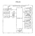
- FIG. 20 is a block diagram of the mobile phone according to the fourth embodiment.
- FIG. 21 is a diagram for explaining how to detect an operation performed for a three-dimensional object in the fourth embodiment.
- FIG. 22 is a diagram of a modified example of the mobile phone according to the fourth embodiment.
- a mobile phone is used to explain as an example of the display device; however, the present invention is not limited to mobile phones. Therefore, the present invention can be applied to a variety of devices, including but not limited to personal handyphone systems (PHS), personal digital assistants (PDA), portable navigation units, personal computers (including but not limited to tablet computers, netbooks etc.), media players, portable electronic reading devices, and gaming devices.
- PHS personal handyphone systems
- PDA personal digital assistants
- portable navigation units personal computers (including but not limited to tablet computers, netbooks etc.), media players, portable electronic reading devices, and gaming devices.
- the present invention can also be applied to stationary electronic devices that have a plurality of display units.
- FIG. 1 is a front view of the mobile phone 1 .
- FIG. 2 is a block diagram of the mobile phone 1 .
- the mobile phone 1 includes an operating unit 13 , a microphone 15 , a receiver 16 , a control unit 22 , a storage unit 24 , a communication unit 26 , a sound processor 30 , a touch panel 32 , an imaging unit 40 , and an imaging unit 42 .
- the operating unit 13 , the microphone 15 , the receiver 16 , the touch panel 32 , and the imaging unit 40 are exposed to the front surface of the mobile phone 1 .
- the operating unit 13 has physical button, and outputs a signal corresponding to a pressed button to the control unit 22 .
- the operating unit 13 has only one button; however, the operating unit 13 may have a plurality of buttons.
- the microphone 15 acquires an external sound.
- the receiver 16 outputs a voice of a call partner during a phone call.
- the sound processor 30 converts the sound input from the microphone 15 to a digital signal and outputs the digital signal to the control unit 22 .
- the sound processor 30 also decodes a digital signal input from the control unit 22 and outputs the decoded signal to the receiver 16 .
- the communication unit 26 includes an antenna 26 a , and establishes a wireless signal path using a code-division multiple access (CDMA) system, or any other wireless communication protocols, with a base station via a channel allocated by the base station, and performs telephone communication and information communication with the base station.
- CDMA code-division multiple access
- Any other wired or wireless communication or network interfaces e.g., LAN, Bluetooth, Wi-Fi, NFC (Near Field Communication) may also be included in lieu of or in addition to the communication unit 26 .
- the touch panel 32 displays various pieces of information such as characters, graphics, and images, and detects an input operation performed on a display area such as icon, button, and character input area.
- the touch panel 32 is structured with a display unit 32 a and a touch sensor 32 b so as to overlap each other.
- the display unit 32 a includes a display device such as a liquid crystal display (LCD) or an organic electro-luminescence display (OELD), and displays various pieces of information according to a control signal input from the control unit 22 .
- the touch sensor 32 b detects an input operation performed on the surface of the touch panel 32 , and outputs a signal corresponding to the detected input operation to the control unit 22 .
- the detection method in which the touch sensor 32 b detects various operations may be any detection method, such as a capacitive type detection method, a resistive type detection method, and a pressure sensitive type detection method.
- the touch panel 32 can display a three-dimensional object.
- a “three-dimensional object” is a display object such as an image and a shape created so as to look as if the display object is three-dimensional using disparity.
- the method of displaying the three-dimensional object may be a method of realizing a stereoscopic vision using a tool such as glasses, or may be a method of realizing a stereoscopic vision with the naked eye.
- the imaging units 40 and 42 electronically photograph an image using an image sensor such as a charge-coupled device (CCD) image sensor or a complementary metal oxide semiconductor (CMOS) image sensor. Each of the imaging units 40 and 42 converts a photographed image to a signal and outputs the signal to the control unit 22 .
- the imaging units 40 and 42 also function as a detector that detects an object for selecting and operating a three-dimensional object in a space in which the three-dimensional object is stereoscopically displayed (hereinafter, also referred to “three-dimensional space”, “stereoscopic vision space” or “visual space”).
- the imaging units 40 and 42 are configured to set a field angle and layout so that, even if an object such as a finger is located in any part of the three-dimensional space, the object can be photographed.
- the imaging units 40 and 42 may be a device that acquires an image of visible light or may be a device that acquires an image of invisible light such as infrared rays.
- the control unit 22 includes a central processing unit (CPU) being a processing unit and a memory being a storage unit, and implements various functions by executing programs using these hardware resources. Specifically, the control unit 22 reads a program or data stored in the storage unit 24 to load it to the memory, and causes the CPU to execute instructions contained in the program loaded to the memory. The control unit 22 performs read/write of data from/to the memory and the storage unit 24 , and controls operations of the communication unit 26 , the display unit 32 a , and the like according to the execution result of the instructions executed by the CPU. When the CPU executes instructions, the data loaded to the memory and the signal input from the touch sensor 32 b or so are used as part of parameters and determination conditions.
- CPU central processing unit
- memory being a storage unit
- the storage unit 24 includes one or more non-transitory storage medium, for example, a nonvolatile memory (such as ROM, EPROM, flash card etc.) and/or a storage device (such as magnetic storage device, optical storage device, solid-state storage device etc.), and stores therein various programs and data. Examples of the program stored in the storage unit 24 include a control program 24 a . Examples of the data stored in the storage unit 24 include object data 24 b and action data 24 c .
- the storage unit 24 may include a combination of a portable storage medium such as a memory card and a reader/writer for reading/writing data from/to the storage medium.
- control program 24 a the object data 24 b , and the action data 24 c may be stored in the storage medium.
- the control program 24 a , the object data 24 b , and the action data 24 c may be acquired from any other device such as a server through communication by the communication unit 26 .
- the control program 24 a provides functions for various controls to operate the mobile phone 1 .
- the function provided by the control program 24 a includes a function for controlling a display of a three-dimensional object on the touch panel 32 and a function for detecting a user's operation performed for the three-dimensional object displayed by the touch panel 32 .
- the object data 24 b contains information for shapes and characteristics of a three-dimensional object.
- the object data 24 b is used to display the three-dimensional object.
- the action data 24 c contains information for how an operation performed for a displayed three-dimensional object acts for the three-dimensional object. When the operation performed for the displayed three-dimensional object is detected, the action data 24 c is used to change the three-dimensional object.
- the change mentioned here includes movement, rotation, deformation, deletion, and so on.
- FIG. 3 and FIG. 4 are diagrams for explaining how to detect an operation of pushing the three-dimensional object and how to change the three-dimensional object according to the detected operation.
- the touch panel 32 stereoscopically displays a three-dimensional object OB 1 in a three-dimensional space 50 .
- the three-dimensional object OB 1 is, for example, an object resembling a ball.
- the touch panel 32 also displays a bottom surface B 1 that supports the three-dimensional object OB 1 .
- Step S 12 the user places a finger F 1 on a location where it is in contact with the three-dimensional object OB 1 , and keeps the finger F 1 still as it is.
- the mobile phone 1 determines that the three-dimensional object OB 1 is selected as an operation target.
- the mobile phone 1 changes a display mode of the three-dimensional object OB 1 , or so, to notify the user that the three-dimensional object OB 1 is selected as the operation target.
- the determination as to whether the object is in contact with the three-dimensional object OB 1 is performed based on an actual position of the object in the three-dimensional space, a shape of the three-dimensional object OB 1 , and a calculated position of the three-dimensional object OB 1 in the three-dimensional space.
- the shape of the three-dimensional object OB 1 is defined in the object data 24 b.
- the actual position of the object is calculated based on images photographed by the imaging units 40 and 42 .
- the actual position of the object may be calculated based on the size of the previously registered object, the sizes of the object in the images, and the positions of the object in the images.
- the actual position of the object may also be calculated by comparing the size and the position of the object in the image photographed by the imaging unit 40 with the size and the position of the object in the image photographed by the imaging unit 42 .
- the detection of the object such as the finger may be implemented using a known technology. When the object is the finger, the process may be performed by setting a position of the tip of the finger as a position of the object.
- a calculated position of the three-dimensional object OB 1 in the three-dimensional space is calculated based on a position of the three-dimensional object OB 1 on the display surface of the touch panel 32 and an amount of “floating” of the three-dimensional object OB 1 in the three-dimensional space.
- the amount of floating of the three-dimensional object OB 1 in the three-dimensional space may be a value determined upon display, or may be a value calculated from a difference between positions of the three-dimensional object OB 1 in an image for a right eye and in an image for a left eye, which are used to stereoscopically display the three-dimensional object OB 1 .
- the notification indicating that it is selected as the operation target is implemented by, for example, changing the whole color of the three-dimensional object OB 1 or changing a color near a location, within the surface of the three-dimensional object OB 1 , where the three-dimensional object OB 1 is in contact with the object.
- a sound and/or a vibration may be used to perform the notification.
- the mobile phone 1 determines that the three-dimensional object OB 1 is selected as the operation target.
- Step S 13 the user causes the finger F 1 to enter the inside of the three-dimensional object OB 1 as if he/she pushes the three-dimensional object OB 1 .
- the mobile phone 1 changes the three-dimensional object OB 1 according to the operation. How to change the three-dimensional object OB 1 is determined based on the type of the three-dimensional object OB 1 defined in the object data 24 b and the rule of the change defined in the action data 24 c in association with the type.
- the mobile phone 1 changes the three-dimensional object OB 1 so that a portion which the finger F 1 has entered is pushed to dent.
- the mobile phone 1 moves the three-dimensional object OB 1 in the direction of forward movement as if it is pushed away by the finger F 1 .
- the three-dimensional object OB 1 is supported by the bottom surface B 1 , so that the three-dimensional object OB 1 moves according to a component of the force applied by the object, that is, a component that acts in a direction parallel to the bottom surface B 1 .
- the three-dimensional object OB 1 is changed based on the object data 24 b and the action data 24 c , which enables the three-dimensional object OB 1 to be variously changed according to each operation.
- the pushing operation is an operation used in various scenes in the real world, and therefore by detecting an operation of pushing the three-dimensional object OB 1 and executing the corresponding process, intuitive and user-friendly operability can be achieved.
- the object used to operate the three-dimensional object is not limited to the finger, and therefore may be a hand, a foot, a stick, a tool, or so.
- a way to change the three-dimensional object OB 1 according to the pushing operation may follow actual physical law or may be that which is actually impossible.
- the mobile phone 1 changes the three-dimensional object according to the operation.
- various operations can be performed for the three-dimensional object.
- a plurality of imaging units are desirably prepared to photograph the finger F 1 or so from different directions so that an obstacle will not cause a blind spot.
- FIG. 5 is a diagram illustrating an example of information stored in the object data 24 b .
- FIG. 6 to FIG. 11 are diagrams illustrating examples of information stored in the action data 24 c.
- the object data 24 b stores therein information including type, shape information, color, transparency, and so on for each three-dimensional object.
- the type indicates physical characteristics of each three-dimensional object.
- the type is represented by a value such as “Rigid body” and “Elastic body”.
- the shape information is information indicating the shape of each three-dimensional object.
- the shape information is, for example, a set of vertex coordinates of faces that form the three-dimensional object.
- the color is surface color of each three-dimensional object.
- the transparency is a degree in which each three-dimensional object transmits light.
- the object data 24 b can hold information for a plurality of three-dimensional objects.
- the action data 24 c stores therein information for changes made when the pushing operation is detected, for each type of three-dimensional objects. As illustrated in FIG. 6 , when the type of the three-dimensional object is “Rigid body”, a change made when the pushing operation is detected differs according to existence of a fulcrum, existence of an obstacle in its pushed direction, and a pushed speed. The obstacle mentioned here indicates some other three-dimensional object. Whether the pushed speed is high or low is determined based on a threshold.
- the three-dimensional object When there is no fulcrum in the three-dimensional object and there is no obstacle in its pushed direction, the three-dimensional object is displayed so as to move in its pushed direction according to a pushed amount. Examples of the three-dimensional object displayed in this manner include blocks, a pen, a book, etc. As for the way to move, whether the three-dimensional object is slid or rotated may be determined based on the shape thereof. Whether the three-dimensional object is moved together with a pushing object or is moved separately from a pushing object as if it is flicked by the pushing object may be determined based on the pushed speed, or may be determined based on a calculated value or a set value of frictional resistance between the three-dimensional object and the bottom surface.
- the three-dimensional object When there is no fulcrum in the three-dimensional object and there is a fixed obstacle in its pushed direction, then the three-dimensional object is displayed so as to move in its pushed direction according to the pushed amount and stop the movement when it comes in contact with the obstacle. Examples of the three-dimensional object displayed in this manner include blocks, a pen, a book, etc. When the pushed speed is high, the three-dimensional object may break the obstacle and continue to move. When the three-dimensional object comes in contact with an obstacle while being moved separately from a pushing object as if it is flicked by the pushing object, the three-dimensional object may be moved in an opposite direction as if it has bounced off the obstacle.
- the three-dimensional object When there is no fulcrum in the three-dimensional object, there is any other rigid body which is not fixed in its pushed direction, and the pushed speed is low, then the three-dimensional object is displayed so as to move in its pushed direction according to the pushed amount and move together with the any other rigid body after the three-dimensional object comes in contact with the any other rigid body.
- the three-dimensional object When there is no fulcrum in the three-dimensional object, there is any other rigid body which is not fixed in its pushed direction, and the pushed speed is high, then the three-dimensional object is displayed so as to move in the pushed direction according to the pushed amount. After the three-dimensional object comes in contact with the any other rigid body, the rigid body is displayed so as to move as if it is flicked by the three-dimensional object.
- the three-dimensional object After coming in contact with any other rigid body, the three-dimensional object may be stopped on that spot, or may continue to move with the speed being slowed down.
- Examples of a combination of the three-dimensional object and the any other rigid body displayed in this manner include a combination of a ball and a pin of bowling, a combination of marbles, etc.
- the three-dimensional object When there is no fulcrum in the three-dimensional object, there is any other rigid body which is not fixed in its pushed direction, and the three-dimensional object can pass through the any other rigid body, then the three-dimensional object is displayed so as to move in its pushed direction according to the pushed amount and pass through the any other rigid body even after the three-dimensional object comes in contact with the any other rigid body, to continuously move as it is.
- a rigid body is impossible to pass through any other rigid body; however, by enabling such a pass, fresh experiment can be provided to the user.
- Examples of a combination of the three-dimensional object and the any other rigid body displayed in this manner include a combination of a ball and a pin of bowling, a combination of marbles, etc. It may be set that the three-dimensional object does not pass through any other rigid body when a threshold is provided with respect to the pushed speed and the pushed speed is slower than the threshold.
- the three-dimensional object When there is a fulcrum in the three-dimensional object, the three-dimensional object is displayed so as to rotate around the fulcrum according to its pushed direction and amount.
- the rotation mentioned here may be continuous rotation through 360 degrees or may be a reciprocating swing motion within a predetermined turning range. Examples of the three-dimensional object displayed in this manner include a pendulum, a sand bag for boxing, a windmill, etc.
- a change made when a pushing operation is detected differs according to a material, existence of limitation to its change amount, and a pushed speed.
- the material mentioned here is an assumed material of the three-dimensional object, which is defined in the object data 24 b.
- the three-dimensional object When the material of the three-dimensional object is a rubber-based material without limitation to its change amount and the pushed speed is low, the three-dimensional object is displayed so as to deform in the pushed direction according to the pushed amount and return to its original shape when it is released from the pushed state.
- the material of the three-dimensional object is a rubber-based material without limitation to its change amount and the pushed speed is high, the three-dimensional object is displayed so as to deform in its pushed direction according to the pushed amount. Thereafter the three-dimensional object is displayed so as to move in the pushed direction as if it is flicked away while returning to its original shape. Examples of the three-dimensional object displayed in this manner include a rubber ball, a rubber eraser, etc.
- the three-dimensional object When the material of the three-dimensional object is a rubber-based material with limitation to the change amount, the three-dimensional object is displayed so as to deform in its pushed direction within a deformable range according to the pushed amount. Then, when the subsequent pushing operation is detected, the three-dimensional object is displayed so as to move in the pushed direction while returning to its original shape. Examples of the three-dimensional object displayed in this manner include a rubber ball, a rubber eraser, etc.
- the three-dimensional object When the material of the three-dimensional object is a metal-based material, the three-dimensional object is displayed so that it is deformed in its pushed direction within a deformable range according to the pushed amount. Then, when it is released from the pushed state, the three-dimensional object is displayed so that returning to its original shape and deformation are repeated (so as to vibrate). If the three-dimensional object is pushed in any direction other than the deformable direction, the three-dimensional object moves similarly to the rigid body. Examples of the three-dimensional object displayed in this manner include a plate spring, a helical spring, etc.
- the three-dimensional object is displayed so that its pushed portion dents and the entire shape is thereby deformed.
- Examples of the three-dimensional object displayed in this manner include clay, etc.
- a change made when the pushing operation is detected differs according to the pushed speed.
- a pushing object is displayed so as to be soaked in the three-dimensional object, that is, in the liquid.
- the pushing object is displayed so that it is soaked in the liquid with ripples spreading across the liquid.
- the pushing object is displayed so that it is soaked in the liquid with water splashes from the liquid. Examples of the three-dimensional object displayed in this manner include water in a cup, etc.
- a change made when the pushing operation is detected differs according to the pushed speed.
- the three-dimensional object that is, the gas is displayed so that it is blocked by the pushing object to float around the periphery thereof.
- the gas is displayed so as to be scattered by the pushing object.
- the pushed speed is high, the gas is displayed so that eddy is produced in the gas due to turbulent flow in the back side of the moving direction of the pushing object. Examples of the three-dimensional object displayed in this manner include smoke, etc.
- the type of the three-dimensional object is “Aggregate”
- a change made when the pushing operation is detected differs according to how elements of the aggregate are combined.
- the three-dimensional object is displayed so that its pushed portion dents and the entire shape as the aggregate is thereby changed. Examples of the three-dimensional object displayed in this manner include sands, sugar, etc.
- the three-dimensional object When the elements of the aggregate are combined, the three-dimensional object is displayed so that its pushed portion dents and the entire shape as the aggregate is thereby changed. Moreover, it may be displayed so that any elements other than the pushed portion move by being pulled by the element of the pushed portion. Examples of the three-dimensional object displayed in this manner include a chain, etc.
- the three-dimensional object When the elements of the aggregate are not combined but attractive force or repulsive force acts between the elements and a pushing object, the three-dimensional object is displayed so as to move without contacting the pushing object.
- the attractive force acts between the elements and the pushing object
- the three-dimensional object is attracted to the pushing object without contacting the pushing object when it enters within a predetermined distance to the pushing object.
- the repulsive force acts between the elements and the pushing object
- the three-dimensional object is repelled from the pushing object without contacting the pushing object when it enters within a predetermined distance to the pushing object.
- Examples of a combination of the three-dimensional object and the pushing object displayed in this manner include a combination of iron powder and a magnet, etc.
- the three-dimensional object can be variously changed according to the pushing operation.
- the information stored in the object data 24 b and in the action data 24 c is not limited to the example, and therefore may be appropriately varied depending on intended use or so. For example, settings may be made so that the way to change the three-dimensional object is switched according to the type and the size of the pushing object and/or the size of a contact area between the pushing object and the three-dimensional object.
- FIG. 12 is a flowchart of a procedure of the contact detecting process of the three-dimensional object.
- the procedure illustrated in FIG. 12 is implemented by the control unit 22 executing the control program 24 a triggered by detection of a predetermined operation or the like.
- the control unit 22 stereoscopically displays a three-dimensional object based on the object data 24 b .
- the object data 24 b may be previously stored in the storage unit 24 or may be acquired from any other device such as a server through communication by the communication unit 26 .
- Step S 102 the control unit 22 determines whether detecting units, that is, the imaging units 40 and 42 have detected a predetermined object.
- the predetermined object is, for example, a user's finger.
- Step S 108 the control unit 22 determines whether operation completion has been detected.
- the operation completion may be detected when a predetermined operation is performed for the operating unit 13 , or may be detected when a predetermined operation is performed for the touch panel 32 .
- the operation completion may also be detected when a predetermined user's hand gesture is photographed by at least one of the imaging units 40 and 42 .
- the control unit 22 ends the contact detecting process.
- the control unit 22 re-executes Step S 102 and the subsequent steps.
- Step S 103 the control unit 22 determines the type of the predetermined object.
- the type of the predetermined object is determined based on the size, the shape, the color, and so on of the object in images photographed by the imaging units 40 and 42 .
- Step S 104 the control unit 22 looks for a three-dimensional object in contact with the predetermined object.
- Step S 108 the control unit 22 determines whether the operation completion has been detected. When the operation completion has been detected (Yes at Step S 108 ), the control unit 22 ends the contact detecting process. When the operation completion has not been detected (No at Step S 108 ), the control unit 22 re-executes Step S 102 and the subsequent steps.
- Step S 106 the control unit 22 determines the type of the three-dimensional object in contact with the predetermined object based on the object data 24 b . Then at Step S 107 , the control unit 22 executes an operation detecting process explained later. Thereafter, at Step S 108 , the control unit 22 determines whether the operation completion has been detected. When the operation completion has been detected (Yes at Step S 108 ), the control unit 22 ends the contact detecting process. When the operation completion has not been detected (No at Step S 108 ), the control unit 22 re-executes Step S 102 and the subsequent steps.
- FIG. 13 is a flowchart of a procedure of the operation detecting process. The procedure illustrated in FIG. 13 is implemented by the control unit 22 executing the control program 24 a.
- Step S 201 the control unit 22 acquires a contact time for which the predetermined object keeps in contact with the three-dimensional object. Then at Step S 202 , the control unit 22 determines whether the predetermined object has been moved to the inside of the three-dimensional object. When the predetermined object has not been moved to the inside of the three-dimensional object (No at Step S 202 ), the control unit 22 re-executes Step S 201 and the subsequent step.
- Step S 203 the control unit 22 determines whether the contact time is longer than a predetermined time.
- the contact time is not longer than the predetermined time (No at Step S 203 )
- Step S 204 the control unit 22 calculates a speed of the predetermined object.
- Step S 205 the control unit changes the three-dimensional object based on the type, the location, and the speed of the predetermined object and based on the type and the like of the three-dimensional object. A specific way to change the three-dimensional object is determined according to the action data 24 c.
- Step S 206 determines at Step S 206 whether the predetermined object has been moved to the outside of the three-dimensional object.
- the control unit 22 re-executes Step S 204 and the subsequent steps.
- Step S 207 the control unit 22 determines whether the change of the three-dimensional object is continued. For example, when it is defined in the action data 24 c that the vibration is continued for a predetermined time even after the release, it is determined that the change of the three-dimensional object is continued.
- Step S 208 the control unit 22 changes the three-dimensional object, and thereafter re-executes Step S 207 and the subsequent step.
- the control unit 22 ends the operation detecting process.
- the first embodiment is configured to variously change the three-dimensional object according to the pushing operation, thus providing a user-friendly operation method to users.
- the mobile phone 1 according to the second embodiment is different in a procedure of the operation detecting process executed based on the functions provided by the control program 24 a from that according to the first embodiment.
- the mobile phone 1 according to the second embodiment is configured in the same manner as that of the mobile phone 1 according to the first embodiment. Therefore, in the second embodiment, explanation that overlaps with the explanation in the first embodiment is omitted, and the operation detecting process will be mainly explained below.
- FIG. 14 is a diagram for explaining how to detect an operation of pushing the three-dimensional object and how to change the three-dimensional object according to the detected operation.
- Step S 21 illustrated in FIG. 14 the user brings the finger F 1 into contact with the three-dimensional object, and at Step S 22 , the user causes the finger F 1 to enter the inside of the three-dimensional object OB 1 .
- the mobile phone 1 determines that the three-dimensional object OB 1 has been selected as the operation target.
- the mobile phone 1 changes the display mode of the three-dimensional object OB 1 , or so, to notify the user that the three-dimensional object OB 1 has been selected as the operation target.
- the mobile phone 1 changes the three-dimensional object OB 1 according to the operation by the finger F 1 after the detection of the contact as if it is already selected as an object of the pushing operation at the stage of Step S 21 .
- the pushing operation can be detected even if the object does not remain in that spot after a contact between the object and the three-dimensional object is detected. Therefore, the user can quickly start the operation of pushing the three-dimensional object.
- an unintended three-dimensional object can be prevented from being selected as an operation target during the process of moving the finger in order to operate any other three-dimensional object.
- FIG. 15 is a flowchart of the procedure of the operation detecting process.
- the procedure illustrated in FIG. 15 is implemented by the control unit 22 executing the control program 24 a . It should be noted that the procedure of the contact detecting process is the same as that illustrated in FIG. 12 .
- Step S 301 the control unit 22 determines whether the predetermined object has been moved to the inside of the three-dimensional object.
- the control unit 22 ends the operation detecting process.
- Step S 302 the control unit 22 determines whether an elapsed time since the detection of the contact is longer than a predetermined time. When the elapsed time is not longer than the predetermined time (No at Step S 302 ), the control unit 22 re-executes Step S 301 and the subsequent step.
- Step S 303 the control unit 22 calculates a speed of the predetermined object.
- Step S 304 the control unit changes the three-dimensional object based on the type, the location, and the speed of the predetermined object and based on the type and the like of the three-dimensional object. A specific way to change the three-dimensional object is determined according to the action data 24 c.
- Step S 305 the control unit 22 determines at Step S 305 whether the predetermined object has been moved to the outside of the three-dimensional object.
- the control unit 22 re-executes Step S 303 and the subsequent steps.
- Step S 306 the control unit 22 determines whether the change of the three-dimensional object is continued. For example, when it is defined in the action data 24 c that the vibration is continued for a predetermined time even after the release, it is determined that the change of the three-dimensional object is continued.
- Step S 307 the control unit 22 changes the three-dimensional object, and thereafter re-executes Step S 306 and the subsequent step.
- the control unit 22 ends the operation detecting process.
- the second embodiment is configured to recognize the pushing operation even when the state in which the object such as the finger is in contact with the three-dimensional object does not continue for a longer period of time than the predetermined time. Therefore, the user can quickly start the operation of pushing the three-dimensional object.
- a third embodiment will be explained below.
- the mobile phone 1 according to the third embodiment is different in a procedure of the operation detecting process executed based on the functions provided by the control program 24 a from that according to the first embodiment.
- the mobile phone 1 according to the third embodiment is configured in the same manner as that of the mobile phone 1 according to the first embodiment. Therefore, in the third embodiment, explanation that overlaps with the explanation in the first embodiment is omitted, and the operation detecting process will be mainly explained below.
- FIG. 16 and FIG. 17 are diagrams for explaining how to detect an operation of pushing the three-dimensional object and how to change the three-dimensional object according to the detected operation.
- the touch panel 32 stereoscopically displays the three-dimensional object OB 1 in the three-dimensional space. The user brings the finger F 1 into contact with the three-dimensional object.
- Step S 32 the mobile phone 1 changes the three-dimensional object OB 1 , from that point on, according to the operation by the finger F 1 .
- the three-dimensional object OB 1 starts moving in synchronization with movement of the finger F 1 .
- the mobile phone 1 determines the three-dimensional object OB 1 as the operation target at the stage when the movement of the finger F 1 to the inside of the three-dimensional object OB 1 has been continued for a longer period of time than the predetermined time.
- the mobile phone 1 changes the display mode of the three-dimensional object OB 1 , or so, to notify the user that the three-dimensional object OB 1 is determined as the operation target. Thereafter, the mobile phone 1 also continues changing the three-dimensional object OB 1 while the movement of the finger F 1 to the inside of the three-dimensional object OB 1 is detected.
- Step S 34 in FIG. 17 when the movement of the finger F 1 to the inside of the three-dimensional object OB 1 becomes undetectable before the predetermined time elapses, the mobile phone 1 adds a reverse change to the change added so far, to the three-dimensional object OB 1 . Consequently, the three-dimensional object OB 1 is displayed at the same position as that at the stage of Step S 31 in the same state.
- the speed of the reverse change added to the three-dimensional object OB 1 may be higher than the speed at which the change is added to the three-dimensional object OB 1 so far. That is, the three-dimensional object OB 1 may be reversely changed as if it is reversely reproduced at a high speed.
- the user can recognize that the three-dimensional object is being selected before the selection is determined. As a result, the user is able to know, at an early point, whether an intended three-dimensional object is selected. When an unintended three-dimensional object is selected, the user can return the unintentionally selected three-dimensional object to its original state by stopping the operation before the predetermined time elapses.
- the three-dimensional object with the change added thereto may be displayed in a mode (e.g., translucent mode) different from the normal mode or from the mode in which the selection as the operation target is determined.
- a mode e.g., translucent mode
- FIG. 18 is a flowchart of the procedure of the operation detecting process.
- the procedure illustrated in FIG. 18 is implemented by the control unit 22 executing the control program 24 a . It should be noted that the procedure of the contact detecting process is the same as that illustrated in FIG. 12 .
- Step S 401 the control unit 22 determines whether the predetermined object has been moved to the inside of the three-dimensional object.
- the control unit 22 ends the operation detecting process.
- Step S 402 the control unit 22 calculates a speed of the predetermined object.
- Step S 403 the control unit changes the three-dimensional object based on the type, the location, and the speed of the predetermined object and based on the type and the like of the three-dimensional object. A specific way to change the three-dimensional object is determined according to the action data 24 c.
- Step S 404 the control unit 22 determines whether an elapsed time since the detection of the contact is longer than a predetermined time.
- the control unit 22 determines whether the movement of the predetermined object to the inside direction of the three-dimensional object is continued.
- Step S 405 When the movement of the predetermined object to the inside direction of the three-dimensional object is continued (Yes at Step S 405 ), the control unit 22 re-executes Step S 402 and the subsequent steps.
- Step S 406 the control unit 22 reversely changes the three-dimensional object OB 1 to be returned to its original state. The control unit 22 then ends the operation detecting process.
- Step S 407 the control unit 22 determines whether the predetermined object has been moved to the outside of the three-dimensional object.
- the control unit 22 re-executes Step S 402 and the subsequent steps.
- Step S 408 the control unit 22 determines whether the change of the three-dimensional object is continued. For example, when it is defined in the action data 24 c that the vibration is continued for a predetermined time even after the release, it is determined that the change of the three-dimensional object is continued.
- Step S 409 the control unit 22 changes the three-dimensional object, and thereafter re-executes Step S 408 and the subsequent step.
- the control unit 22 ends the operation detecting process.
- the third embodiment is configured to change the three-dimensional object according to the operation from the time when the pushing operation is detected. Therefore, the user can thereby easily recognize the three-dimensional object determined as a target of the pushing operation.
- a fourth embodiment will be explained below.
- the embodiments are configured to detect the object that operates the three-dimensional object based on the images photographed by the imaging units; however, some other detection methods may be used.
- a capacitive type touch sensor can detect a position of a finger that does not touch the touch sensor by increasing its sensitivity. Therefore, an example of using the touch sensor as a detector that detects an object operating a three-dimensional object is explained in the fourth embodiment.
- the same signs as these of the already explained components are assigned to the same components as the already explained components. Explanation that overlaps with the above explanation may be omitted.
- FIG. 19 is a front view of the mobile phone 2 .
- FIG. 20 is a block diagram of the mobile phone 2 .
- the mobile phone 2 includes the operating unit 13 , the microphone 15 , the receiver 16 , the control unit 22 , the storage unit 24 , the communication unit 26 , the sound processor 30 , and the touch panel 32 .
- the touch panel 32 displays various pieces of information such as characters, graphics, and images, and detects an input operation performed on a predetermined display area such as icon, button, and character input area.
- the touch panel 32 is structured with the display unit 32 a and the touch sensor 32 b so as to overlap each other.
- the touch sensor 32 b according to the present embodiment is a capacitive type touch sensor.
- the touch sensor 32 b functions also as a detector that detects fingers operating a three-dimensional object.
- FIG. 21 is a diagram for explaining how to detect an operation performed for a three-dimensional object.
- the touch panel 32 stereoscopically displays the three-dimensional object OB 1 in the three-dimensional space.
- the user brings the finger F 1 into contact with the three-dimensional object OB 1 .
- the mobile phone 2 detects a location of the finger F 1 using the touch sensor 32 b .
- the touch sensor 32 b can detect the location of the finger F 1 in an X-axis direction and a Y-axis direction by increasing its sensitivity even if, for example, a distance from the finger F 1 to the surface of the touch panel 32 in a Z-axis direction is about 10 cm.
- the touch sensor 32 b can also detect a distance D 2 from the finger F 1 to the surface of the touch panel 32 in the Z-axis direction based on the magnitude of the capacitance.
- the mobile phone 2 can detect the contact between the finger F 1 and the three-dimensional object OB 1 and can detect the operation of pushing the three-dimensional object OB 1 performed by the finger F 1 , based on the thus detected location of the finger F 1 in the three-dimensional space.
- the fourth embodiment is configured to use the touch sensor as a detector, so that the operation performed for the three-dimensional object can be detected even by a display device without the imaging unit.
- the imaging unit and the touch sensor may be used in combination with each other.
- respective detection results may be averaged to specify the location of the finger F 1 .
- a weighted average may be used, such that weighting of the detection results of the touch sensor is increased in an area near the touch panel 32 where the imaging unit 40 is difficult to acquire the image of the finger F 1 and weighting of the detection results of the imaging unit 40 is increased in an area far from the touch panel 32 where the detection precision of the touch sensor becomes low.
- FIG. 22 is a diagram of a configuration example of a mobile phone 3 that uses a plurality of touch sensors to detect an operation performed for the three-dimensional object.
- the mobile phone 3 includes a first housing 3 a , a second housing 3 b , and a hinge 3 c .
- the hinge 3 c couples the first housing 3 a and the second housing 3 b so as to be openable and closable.
- the first housing 3 a is provided with the touch panel 32 including the touch sensor 32 b
- the second housing 3 b is provided with a touch panel 34 including a touch sensor 34 b .
- the touch sensor 32 b and the touch sensor 34 b contact the three-dimensional space at different angles when the first housing 3 a and the second housing 3 b are fixed to each other at an angle of about 90 degrees.
- the touch sensor 32 b can detect the location of the finger F 1 in the X-axis direction and the Y-axis direction.
- the touch sensor 32 b can also detect the distance D 2 from the finger F 1 to the surface of the touch panel 32 in the Z-axis direction, based on the magnitude of the capacitance.
- the touch sensor 34 b can detect the location of the finger F 1 in the X-axis direction and the Z-axis direction.
- the touch sensor 34 b can also detect a distance D 4 from the finger F 1 to the surface of the touch panel 34 in the Y-axis direction, based on the magnitude of the capacitance.
- one of the touch panels may display the three-dimensional object, and the other touch panel may stop displaying or may two-dimensionally display guidance or so.
- the touch panel which does not display the three-dimensional object may be configured as a mere touch sensor.
- a three-dimensional object (display object) being an operation target may be any object resembling an object actually existing such as a book, blocks, a spoon, chopsticks, playing cards, clay, and an instrument, or may be any object not existing such as a virtual avatar, a character in a game, and an augmented reality (AR) tag in virtual reality.
- the change added to the three-dimensional object according to the detected operation is not limited to the movement, the deformation, the deletion, or the like.
- the change added to the three-dimensional object according to the pushing operation is not limited to these of the embodiments, and may therefore be changed according to the type of the three-dimensional object.
- the clay when a three-dimensional object resembling clay (hereinafter, “clay”) is determined as an operation target, the clay may be deformed according to the pushing operation, so that the user can form the clay into an arbitrary shape.
- the viscosity of the clay may be decreased with the elapse of time as if the clay is getting dry.
- the viscosity of the clay may be increased.
- phonograph record When a three-dimensional object resembling a phonograph record (hereinafter, “phonograph record”) is determined as an operation target, it may be set so that the phonograph record is rotated around its center and a sound is reproduced according to the pushing operation. By synchronizing the rotation with the sound reproduction, a technique such as a scratch performed by a disc jockey may be virtually achieved.
- control program 24 a represented in the embodiments may be divided into a plurality of modules or may be integrated with any other program.
- the fingers are used to operate the three-dimensional object; however, a stick-like object or so of which end can be charged with static electricity may be used instead of the fingers.
- the example of using the imaging units and the touch sensor are used as a detector in order to detect the three-dimensional object; however, the detector is not limited thereto.
- a sensor using a Time-of-Flight (TOF) method may be used instead of the imaging unit.
- TOF Time-of-Flight
- a plurality of proximity sensor or the like capable of detecting a movement of the three-dimensional object in a planar direction of the three-dimensional space are arranged substantially horizontally with respect to a moving direction of the object, displacement of the object can be detected even in a noncontact manner, and therefore these devices may also be used. It is preferable that the displacement of the object can be detected without providing the sensor or the like in the object. If the sensor or the like is not provided in the object, then this does not have to attach an acceleration sensor to the finger or does not have to move a display device itself with an acceleration sensor, which leads to cost reduction.
- the present invention is also applicable to a case of representing the three-dimensional object as if it is present in a deeper side than the display unit.
- a sensor and a camera may be provided in the back side of the display unit.
- the display device is a mobile phone
- many mobile phones are provided with an in-camera for photographing the user himself/herself and an out-camera for photographing landscapes and the like. Therefore, it may be configured to capture the displacement of the object in the back side by using the out-camera.
- the embodiments are configured that the display device singly detects an operation performed for the three-dimensional object; however, the display device may collaborate with a server to detect an operation performed for the three-dimensional object. In this case, the display device successively transmits information detected by the detector to the server, and the server detects the operation to notify the display device of the detection result.
- the display device singly detects an operation performed for the three-dimensional object; however, the display device may collaborate with a server to detect an operation performed for the three-dimensional object.
- the display device successively transmits information detected by the detector to the server, and the server detects the operation to notify the display device of the detection result.
- one embodiment of the invention provides a display device that can provide the user with convenient operations.
Abstract
According to an aspect, a display device includes a display unit and a control unit. The display unit stereoscopically displays a display object. When a movement of an object is detected in a three-dimensional space where the display object is stereoscopically displayed, the control unit for changes the display object in the three-dimensional space according to the movement of the object.
Description
The present application is a continuation of U.S. patent application Ser. No. 13/532,885 filed on Jun. 26, 2012, which claims priority from Japanese Application No. 2011-143070, filed on Jun. 28, 2011. The disclosures of all of the above-listed prior-filed applications are hereby incorporated by reference herein in their entirety.
The present disclosure relates to a display device.
Some display devices such as mobile phones with a display unit can stereoscopically display an image and so on (see e.g., Japanese Patent Application Laid-open No. 2011-95547). The three-dimensional display is implemented by using binocular disparity.
The three-dimensional display is a user-friendly display manner; however, it has been used just for viewing purposes, and has not been used for improving the convenience of operations.
For the foregoing reasons, there is a need for a display device that can provide the user with convenient operations using the three-dimensional display.
According to an aspect, a display device includes a display unit, a detecting unit, and a control unit. The display unit stereoscopically displays a display object. The detecting unit detects an object in a three-dimensional space where the display object is stereoscopically displayed. When a movement of the object is detected in the three-dimensional space, the control unit changes the display object according to the movement of the object.
According to another aspect, a display device includes a display unit and a control unit. The display unit stereoscopically displays a display object. When a movement of an object is detected in a three-dimensional space where the display object is stereoscopically displayed, the control unit for changes the display object in the three-dimensional space according to the movement of the object.
Exemplary embodiments of the present invention will be explained in detail below with reference to the accompanying drawings. It should be noted that the present invention is not limited by the following explanation. In addition, this disclosure encompasses not only the components specifically described in the explanation below, but also those which would be apparent to persons ordinarily skilled in the art, upon reading this disclosure, as being interchangeable with or equivalent to the specifically described components.
In the following description, a mobile phone is used to explain as an example of the display device; however, the present invention is not limited to mobile phones. Therefore, the present invention can be applied to a variety of devices, including but not limited to personal handyphone systems (PHS), personal digital assistants (PDA), portable navigation units, personal computers (including but not limited to tablet computers, netbooks etc.), media players, portable electronic reading devices, and gaming devices. The present invention can also be applied to stationary electronic devices that have a plurality of display units.
First of all, the configuration of a mobile phone (display device) 1 according to a first embodiment will be explained below with reference to FIG. 1 and FIG. 2 . FIG. 1 is a front view of the mobile phone 1. FIG. 2 is a block diagram of the mobile phone 1.
As illustrated in FIG. 1 and FIG. 2 , the mobile phone 1 includes an operating unit 13, a microphone 15, a receiver 16, a control unit 22, a storage unit 24, a communication unit 26, a sound processor 30, a touch panel 32, an imaging unit 40, and an imaging unit 42. The operating unit 13, the microphone 15, the receiver 16, the touch panel 32, and the imaging unit 40 are exposed to the front surface of the mobile phone 1.
The operating unit 13 has physical button, and outputs a signal corresponding to a pressed button to the control unit 22. In the example illustrated in FIG. 1 , the operating unit 13 has only one button; however, the operating unit 13 may have a plurality of buttons.
The microphone 15 acquires an external sound. The receiver 16 outputs a voice of a call partner during a phone call. The sound processor 30 converts the sound input from the microphone 15 to a digital signal and outputs the digital signal to the control unit 22. The sound processor 30 also decodes a digital signal input from the control unit 22 and outputs the decoded signal to the receiver 16.
The communication unit 26 includes an antenna 26 a, and establishes a wireless signal path using a code-division multiple access (CDMA) system, or any other wireless communication protocols, with a base station via a channel allocated by the base station, and performs telephone communication and information communication with the base station. Any other wired or wireless communication or network interfaces, e.g., LAN, Bluetooth, Wi-Fi, NFC (Near Field Communication) may also be included in lieu of or in addition to the communication unit 26.
The touch panel 32 displays various pieces of information such as characters, graphics, and images, and detects an input operation performed on a display area such as icon, button, and character input area. The touch panel 32 is structured with a display unit 32 a and a touch sensor 32 b so as to overlap each other.
The display unit 32 a includes a display device such as a liquid crystal display (LCD) or an organic electro-luminescence display (OELD), and displays various pieces of information according to a control signal input from the control unit 22. The touch sensor 32 b detects an input operation performed on the surface of the touch panel 32, and outputs a signal corresponding to the detected input operation to the control unit 22. The detection method in which the touch sensor 32 b detects various operations may be any detection method, such as a capacitive type detection method, a resistive type detection method, and a pressure sensitive type detection method.
The touch panel 32 can display a three-dimensional object. A “three-dimensional object” is a display object such as an image and a shape created so as to look as if the display object is three-dimensional using disparity. The method of displaying the three-dimensional object may be a method of realizing a stereoscopic vision using a tool such as glasses, or may be a method of realizing a stereoscopic vision with the naked eye.
The imaging units 40 and 42 electronically photograph an image using an image sensor such as a charge-coupled device (CCD) image sensor or a complementary metal oxide semiconductor (CMOS) image sensor. Each of the imaging units 40 and 42 converts a photographed image to a signal and outputs the signal to the control unit 22. The imaging units 40 and 42 also function as a detector that detects an object for selecting and operating a three-dimensional object in a space in which the three-dimensional object is stereoscopically displayed (hereinafter, also referred to “three-dimensional space”, “stereoscopic vision space” or “visual space”).
The imaging units 40 and 42 are configured to set a field angle and layout so that, even if an object such as a finger is located in any part of the three-dimensional space, the object can be photographed. The imaging units 40 and 42 may be a device that acquires an image of visible light or may be a device that acquires an image of invisible light such as infrared rays.
The control unit 22 includes a central processing unit (CPU) being a processing unit and a memory being a storage unit, and implements various functions by executing programs using these hardware resources. Specifically, the control unit 22 reads a program or data stored in the storage unit 24 to load it to the memory, and causes the CPU to execute instructions contained in the program loaded to the memory. The control unit 22 performs read/write of data from/to the memory and the storage unit 24, and controls operations of the communication unit 26, the display unit 32 a, and the like according to the execution result of the instructions executed by the CPU. When the CPU executes instructions, the data loaded to the memory and the signal input from the touch sensor 32 b or so are used as part of parameters and determination conditions.
The storage unit 24 includes one or more non-transitory storage medium, for example, a nonvolatile memory (such as ROM, EPROM, flash card etc.) and/or a storage device (such as magnetic storage device, optical storage device, solid-state storage device etc.), and stores therein various programs and data. Examples of the program stored in the storage unit 24 include a control program 24 a. Examples of the data stored in the storage unit 24 include object data 24 b and action data 24 c. The storage unit 24 may include a combination of a portable storage medium such as a memory card and a reader/writer for reading/writing data from/to the storage medium. In this case, the control program 24 a, the object data 24 b, and the action data 24 c may be stored in the storage medium. The control program 24 a, the object data 24 b, and the action data 24 c may be acquired from any other device such as a server through communication by the communication unit 26.
The control program 24 a provides functions for various controls to operate the mobile phone 1. The function provided by the control program 24 a includes a function for controlling a display of a three-dimensional object on the touch panel 32 and a function for detecting a user's operation performed for the three-dimensional object displayed by the touch panel 32.
The object data 24 b contains information for shapes and characteristics of a three-dimensional object. The object data 24 b is used to display the three-dimensional object. The action data 24 c contains information for how an operation performed for a displayed three-dimensional object acts for the three-dimensional object. When the operation performed for the displayed three-dimensional object is detected, the action data 24 c is used to change the three-dimensional object. The change mentioned here includes movement, rotation, deformation, deletion, and so on.
Then, detection of an operation for pushing a three-dimensional object and a change of the three-dimensional object according to the detected operation will be explained below with reference to FIG. 3 and FIG. 4 . FIG. 3 and FIG. 4 are diagrams for explaining how to detect an operation of pushing the three-dimensional object and how to change the three-dimensional object according to the detected operation. At Step S11 illustrated in FIG. 3 , the touch panel 32 stereoscopically displays a three-dimensional object OB1 in a three-dimensional space 50. The three-dimensional object OB1 is, for example, an object resembling a ball. At Step S11, the touch panel 32 also displays a bottom surface B1 that supports the three-dimensional object OB1.
At Step S12, the user places a finger F1 on a location where it is in contact with the three-dimensional object OB1, and keeps the finger F1 still as it is. When an actual object is detected in the three-dimensional space and a state in which the object keeps in contact with the three-dimensional object OB1 continues for a longer period of time than a predetermined time, the mobile phone 1 determines that the three-dimensional object OB1 is selected as an operation target. The mobile phone 1 changes a display mode of the three-dimensional object OB1, or so, to notify the user that the three-dimensional object OB1 is selected as the operation target.
The determination as to whether the object is in contact with the three-dimensional object OB1 is performed based on an actual position of the object in the three-dimensional space, a shape of the three-dimensional object OB1, and a calculated position of the three-dimensional object OB1 in the three-dimensional space. The shape of the three-dimensional object OB1 is defined in the object data 24 b.
The actual position of the object is calculated based on images photographed by the imaging units 40 and 42. The actual position of the object may be calculated based on the size of the previously registered object, the sizes of the object in the images, and the positions of the object in the images. The actual position of the object may also be calculated by comparing the size and the position of the object in the image photographed by the imaging unit 40 with the size and the position of the object in the image photographed by the imaging unit 42. The detection of the object such as the finger may be implemented using a known technology. When the object is the finger, the process may be performed by setting a position of the tip of the finger as a position of the object.
A calculated position of the three-dimensional object OB1 in the three-dimensional space is calculated based on a position of the three-dimensional object OB1 on the display surface of the touch panel 32 and an amount of “floating” of the three-dimensional object OB1 in the three-dimensional space. The amount of floating of the three-dimensional object OB1 in the three-dimensional space may be a value determined upon display, or may be a value calculated from a difference between positions of the three-dimensional object OB1 in an image for a right eye and in an image for a left eye, which are used to stereoscopically display the three-dimensional object OB1.
The notification indicating that it is selected as the operation target is implemented by, for example, changing the whole color of the three-dimensional object OB1 or changing a color near a location, within the surface of the three-dimensional object OB1, where the three-dimensional object OB1 is in contact with the object. Instead of or in addition to such visual notification, a sound and/or a vibration may be used to perform the notification.
In this way, when the state where the real object such as the finger is in contact with the three-dimensional object OB1 is continuously detected for a longer period of time than a predetermined time, the mobile phone 1 determines that the three-dimensional object OB1 is selected as the operation target. By adding the continuous detection of the contact state for a longer period of time than the predetermined time to the condition, an unintended three-dimensional object can be prevented from being selected as an operation target during the process of moving the finger in order to operate any other three-dimensional object.
It is assumed that after the selection of the three-dimensional object OB1 as the operation target, as illustrated at Step S13, the user causes the finger F1 to enter the inside of the three-dimensional object OB1 as if he/she pushes the three-dimensional object OB1. When the operation of causing the object to enter the inside of the three-dimensional object OB1 selected as the operation target is detected, the mobile phone 1 changes the three-dimensional object OB1 according to the operation. How to change the three-dimensional object OB1 is determined based on the type of the three-dimensional object OB1 defined in the object data 24 b and the rule of the change defined in the action data 24 c in association with the type.
For example, it is assumed that it is defined in the object data 24 b that the three-dimensional object OB1 is an elastic body and it is also defined in the action data 24 c that if the elastic body is pushed, then it is deformed in its pushed direction according to the pushed amount. In this case, as illustrated at S14, the mobile phone 1 changes the three-dimensional object OB1 so that a portion which the finger F1 has entered is pushed to dent.
Alternatively, it is assumed that it is defined in the object data 24 b that the three-dimensional object OB1 is a rigid body and it is also defined in the action data 24 c that if the rigid body is pushed, then it is moved in its pushed direction according to the pushed amount. In this case, as illustrated at Step S15 in FIG. 4 , the mobile phone 1 moves the three-dimensional object OB1 in the direction of forward movement as if it is pushed away by the finger F1. At Step S15 in FIG. 4 , the three-dimensional object OB1 is supported by the bottom surface B1, so that the three-dimensional object OB1 moves according to a component of the force applied by the object, that is, a component that acts in a direction parallel to the bottom surface B1.
In this way, when the operation of pushing the three-dimensional object OB1 is detected, the three-dimensional object OB1 is changed based on the object data 24 b and the action data 24 c, which enables the three-dimensional object OB1 to be variously changed according to each operation. The pushing operation is an operation used in various scenes in the real world, and therefore by detecting an operation of pushing the three-dimensional object OB1 and executing the corresponding process, intuitive and user-friendly operability can be achieved.
The object used to operate the three-dimensional object is not limited to the finger, and therefore may be a hand, a foot, a stick, a tool, or so. A way to change the three-dimensional object OB1 according to the pushing operation may follow actual physical law or may be that which is actually impossible.
When the pushed direction of the three-dimensional object is not parallel to the display surface of the touch panel 32, that is, when the moving direction of the detected object intersects the display surface of the touch panel 32 or intersects a horizontal plane parallel to the display surface thereof, the mobile phone 1 changes the three-dimensional object according to the operation. In this way, by stereoscopically determining the operation of pushing the three-dimensional object, various operations can be performed for the three-dimensional object. To stereoscopically determine the operation of pushing the three-dimensional object, a plurality of imaging units are desirably prepared to photograph the finger F1 or so from different directions so that an obstacle will not cause a blind spot.
The object data 24 b and the action data 24 c illustrated in FIG. 2 will be explained in more detail below with reference to FIG. 5 to FIG. 11 . FIG. 5 is a diagram illustrating an example of information stored in the object data 24 b. FIG. 6 to FIG. 11 are diagrams illustrating examples of information stored in the action data 24 c.
As illustrated in FIG. 5 , the object data 24 b stores therein information including type, shape information, color, transparency, and so on for each three-dimensional object. The type indicates physical characteristics of each three-dimensional object. The type is represented by a value such as “Rigid body” and “Elastic body”. The shape information is information indicating the shape of each three-dimensional object. The shape information is, for example, a set of vertex coordinates of faces that form the three-dimensional object. The color is surface color of each three-dimensional object. The transparency is a degree in which each three-dimensional object transmits light. The object data 24 b can hold information for a plurality of three-dimensional objects.
The action data 24 c stores therein information for changes made when the pushing operation is detected, for each type of three-dimensional objects. As illustrated in FIG. 6 , when the type of the three-dimensional object is “Rigid body”, a change made when the pushing operation is detected differs according to existence of a fulcrum, existence of an obstacle in its pushed direction, and a pushed speed. The obstacle mentioned here indicates some other three-dimensional object. Whether the pushed speed is high or low is determined based on a threshold.
When there is no fulcrum in the three-dimensional object and there is no obstacle in its pushed direction, the three-dimensional object is displayed so as to move in its pushed direction according to a pushed amount. Examples of the three-dimensional object displayed in this manner include blocks, a pen, a book, etc. As for the way to move, whether the three-dimensional object is slid or rotated may be determined based on the shape thereof. Whether the three-dimensional object is moved together with a pushing object or is moved separately from a pushing object as if it is flicked by the pushing object may be determined based on the pushed speed, or may be determined based on a calculated value or a set value of frictional resistance between the three-dimensional object and the bottom surface.
When there is no fulcrum in the three-dimensional object and there is a fixed obstacle in its pushed direction, then the three-dimensional object is displayed so as to move in its pushed direction according to the pushed amount and stop the movement when it comes in contact with the obstacle. Examples of the three-dimensional object displayed in this manner include blocks, a pen, a book, etc. When the pushed speed is high, the three-dimensional object may break the obstacle and continue to move. When the three-dimensional object comes in contact with an obstacle while being moved separately from a pushing object as if it is flicked by the pushing object, the three-dimensional object may be moved in an opposite direction as if it has bounced off the obstacle.
When there is no fulcrum in the three-dimensional object, there is any other rigid body which is not fixed in its pushed direction, and the pushed speed is low, then the three-dimensional object is displayed so as to move in its pushed direction according to the pushed amount and move together with the any other rigid body after the three-dimensional object comes in contact with the any other rigid body. When there is no fulcrum in the three-dimensional object, there is any other rigid body which is not fixed in its pushed direction, and the pushed speed is high, then the three-dimensional object is displayed so as to move in the pushed direction according to the pushed amount. After the three-dimensional object comes in contact with the any other rigid body, the rigid body is displayed so as to move as if it is flicked by the three-dimensional object. After coming in contact with any other rigid body, the three-dimensional object may be stopped on that spot, or may continue to move with the speed being slowed down. Examples of a combination of the three-dimensional object and the any other rigid body displayed in this manner include a combination of a ball and a pin of bowling, a combination of marbles, etc.
When there is no fulcrum in the three-dimensional object, there is any other rigid body which is not fixed in its pushed direction, and the three-dimensional object can pass through the any other rigid body, then the three-dimensional object is displayed so as to move in its pushed direction according to the pushed amount and pass through the any other rigid body even after the three-dimensional object comes in contact with the any other rigid body, to continuously move as it is. In reality, a rigid body is impossible to pass through any other rigid body; however, by enabling such a pass, fresh experiment can be provided to the user. Examples of a combination of the three-dimensional object and the any other rigid body displayed in this manner include a combination of a ball and a pin of bowling, a combination of marbles, etc. It may be set that the three-dimensional object does not pass through any other rigid body when a threshold is provided with respect to the pushed speed and the pushed speed is slower than the threshold.
When there is a fulcrum in the three-dimensional object, the three-dimensional object is displayed so as to rotate around the fulcrum according to its pushed direction and amount. The rotation mentioned here may be continuous rotation through 360 degrees or may be a reciprocating swing motion within a predetermined turning range. Examples of the three-dimensional object displayed in this manner include a pendulum, a sand bag for boxing, a windmill, etc.
As illustrated in FIG. 7 , when the type of the three-dimensional object is “Elastic body”, a change made when a pushing operation is detected differs according to a material, existence of limitation to its change amount, and a pushed speed. The material mentioned here is an assumed material of the three-dimensional object, which is defined in the object data 24 b.
When the material of the three-dimensional object is a rubber-based material without limitation to its change amount and the pushed speed is low, the three-dimensional object is displayed so as to deform in the pushed direction according to the pushed amount and return to its original shape when it is released from the pushed state. When the material of the three-dimensional object is a rubber-based material without limitation to its change amount and the pushed speed is high, the three-dimensional object is displayed so as to deform in its pushed direction according to the pushed amount. Thereafter the three-dimensional object is displayed so as to move in the pushed direction as if it is flicked away while returning to its original shape. Examples of the three-dimensional object displayed in this manner include a rubber ball, a rubber eraser, etc.
When the material of the three-dimensional object is a rubber-based material with limitation to the change amount, the three-dimensional object is displayed so as to deform in its pushed direction within a deformable range according to the pushed amount. Then, when the subsequent pushing operation is detected, the three-dimensional object is displayed so as to move in the pushed direction while returning to its original shape. Examples of the three-dimensional object displayed in this manner include a rubber ball, a rubber eraser, etc.
When the material of the three-dimensional object is a metal-based material, the three-dimensional object is displayed so that it is deformed in its pushed direction within a deformable range according to the pushed amount. Then, when it is released from the pushed state, the three-dimensional object is displayed so that returning to its original shape and deformation are repeated (so as to vibrate). If the three-dimensional object is pushed in any direction other than the deformable direction, the three-dimensional object moves similarly to the rigid body. Examples of the three-dimensional object displayed in this manner include a plate spring, a helical spring, etc.
As illustrated in FIG. 8 , when the type of the three-dimensional object is “Plastic body”, the three-dimensional object is displayed so that its pushed portion dents and the entire shape is thereby deformed. Examples of the three-dimensional object displayed in this manner include clay, etc.
As illustrated in FIG. 9 , when the type of the three-dimensional object is “Liquid”, a change made when the pushing operation is detected differs according to the pushed speed. When the pushed speed is low, a pushing object is displayed so as to be soaked in the three-dimensional object, that is, in the liquid. When the pushed speed is medium, the pushing object is displayed so that it is soaked in the liquid with ripples spreading across the liquid. When the pushed speed is high, the pushing object is displayed so that it is soaked in the liquid with water splashes from the liquid. Examples of the three-dimensional object displayed in this manner include water in a cup, etc.
As illustrated in FIG. 10 , when the type of the three-dimensional object is “Gas”, a change made when the pushing operation is detected differs according to the pushed speed. When the pushed speed is low, the three-dimensional object, that is, the gas is displayed so that it is blocked by the pushing object to float around the periphery thereof. When the pushed speed is medium, the gas is displayed so as to be scattered by the pushing object. When the pushed speed is high, the gas is displayed so that eddy is produced in the gas due to turbulent flow in the back side of the moving direction of the pushing object. Examples of the three-dimensional object displayed in this manner include smoke, etc.
As illustrated in FIG. 11 , when the type of the three-dimensional object is “Aggregate”, a change made when the pushing operation is detected differs according to how elements of the aggregate are combined. When the elements of the aggregate are not combined, the three-dimensional object is displayed so that its pushed portion dents and the entire shape as the aggregate is thereby changed. Examples of the three-dimensional object displayed in this manner include sands, sugar, etc.
When the elements of the aggregate are combined, the three-dimensional object is displayed so that its pushed portion dents and the entire shape as the aggregate is thereby changed. Moreover, it may be displayed so that any elements other than the pushed portion move by being pulled by the element of the pushed portion. Examples of the three-dimensional object displayed in this manner include a chain, etc.
When the elements of the aggregate are not combined but attractive force or repulsive force acts between the elements and a pushing object, the three-dimensional object is displayed so as to move without contacting the pushing object. When the attractive force acts between the elements and the pushing object, the three-dimensional object is attracted to the pushing object without contacting the pushing object when it enters within a predetermined distance to the pushing object. When the repulsive force acts between the elements and the pushing object, the three-dimensional object is repelled from the pushing object without contacting the pushing object when it enters within a predetermined distance to the pushing object. Examples of a combination of the three-dimensional object and the pushing object displayed in this manner include a combination of iron powder and a magnet, etc.
In this manner, by changing the three-dimensional object based on the information stored in the object data 24 b and the information stored in the action data 24 c, the three-dimensional object can be variously changed according to the pushing operation. The information stored in the object data 24 b and in the action data 24 c is not limited to the example, and therefore may be appropriately varied depending on intended use or so. For example, settings may be made so that the way to change the three-dimensional object is switched according to the type and the size of the pushing object and/or the size of a contact area between the pushing object and the three-dimensional object.
Then, a procedure performed by the mobile phone 1 related to the operation of pushing the three-dimensional object will be explained with reference to FIG. 12 and FIG. 13 . FIG. 12 is a flowchart of a procedure of the contact detecting process of the three-dimensional object. The procedure illustrated in FIG. 12 is implemented by the control unit 22 executing the control program 24 a triggered by detection of a predetermined operation or the like.
As illustrated in FIG. 12 , first of all, at Step S101, the control unit 22 stereoscopically displays a three-dimensional object based on the object data 24 b. The object data 24 b may be previously stored in the storage unit 24 or may be acquired from any other device such as a server through communication by the communication unit 26.
Subsequently, at Step S102, the control unit 22 determines whether detecting units, that is, the imaging units 40 and 42 have detected a predetermined object. The predetermined object is, for example, a user's finger. When the predetermined object has not been detected (No at Step S102), then at Step S108, the control unit 22 determines whether operation completion has been detected.
For example, the operation completion may be detected when a predetermined operation is performed for the operating unit 13, or may be detected when a predetermined operation is performed for the touch panel 32. The operation completion may also be detected when a predetermined user's hand gesture is photographed by at least one of the imaging units 40 and 42. When the operation completion has been detected (Yes at Step S108), the control unit 22 ends the contact detecting process. When the operation completion has not been detected (No at Step S108), the control unit 22 re-executes Step S102 and the subsequent steps.
When the predetermined object has been detected (Yes at Step S102), then at Step S103, the control unit 22 determines the type of the predetermined object. The type of the predetermined object is determined based on the size, the shape, the color, and so on of the object in images photographed by the imaging units 40 and 42. Subsequently, at Step S104, the control unit 22 looks for a three-dimensional object in contact with the predetermined object.
When there is no three-dimensional object in contact with the predetermined object (No at Step S105), then at Step S108, the control unit 22 determines whether the operation completion has been detected. When the operation completion has been detected (Yes at Step S108), the control unit 22 ends the contact detecting process. When the operation completion has not been detected (No at Step S108), the control unit 22 re-executes Step S102 and the subsequent steps.
When the three-dimensional object in contact with the predetermined object has been found (Yes at Step S105), then at Step S106, the control unit 22 determines the type of the three-dimensional object in contact with the predetermined object based on the object data 24 b. Then at Step S107, the control unit 22 executes an operation detecting process explained later. Thereafter, at Step S108, the control unit 22 determines whether the operation completion has been detected. When the operation completion has been detected (Yes at Step S108), the control unit 22 ends the contact detecting process. When the operation completion has not been detected (No at Step S108), the control unit 22 re-executes Step S102 and the subsequent steps.
As illustrated in FIG. 13 , first of all, at Step S201, the control unit 22 acquires a contact time for which the predetermined object keeps in contact with the three-dimensional object. Then at Step S202, the control unit 22 determines whether the predetermined object has been moved to the inside of the three-dimensional object. When the predetermined object has not been moved to the inside of the three-dimensional object (No at Step S202), the control unit 22 re-executes Step S201 and the subsequent step.
When the predetermined object has been moved to the inside of the three-dimensional object (Yes at Step S202), then at Step S203, the control unit 22 determines whether the contact time is longer than a predetermined time. When the contact time is not longer than the predetermined time (No at Step S203), it is determined that the three-dimensional object is not the operation target, and therefore the control unit 22 ends the operation detecting process.
When the contact time is longer than the predetermined time (Yes at Step S203), then at Step S204, the control unit 22 calculates a speed of the predetermined object. At Step S205, the control unit changes the three-dimensional object based on the type, the location, and the speed of the predetermined object and based on the type and the like of the three-dimensional object. A specific way to change the three-dimensional object is determined according to the action data 24 c.
Subsequently, the control unit 22 determines at Step S206 whether the predetermined object has been moved to the outside of the three-dimensional object. When the predetermined object has not been moved to the outside of the three-dimensional object, that is, when the pushing operation is continued (No at Step S206), the control unit 22 re-executes Step S204 and the subsequent steps.
When the predetermined object has been moved to the outside of the three-dimensional object, that is, when the three-dimensional object has been released (Yes at Step S206), then at Step S207, the control unit 22 determines whether the change of the three-dimensional object is continued. For example, when it is defined in the action data 24 c that the vibration is continued for a predetermined time even after the release, it is determined that the change of the three-dimensional object is continued.
When the change of the three-dimensional object is continued (Yes at Step S207), then at Step S208, the control unit 22 changes the three-dimensional object, and thereafter re-executes Step S207 and the subsequent step. When the change of the three-dimensional object is not continued (No at Step S207), the control unit 22 ends the operation detecting process.
As explained above, the first embodiment is configured to variously change the three-dimensional object according to the pushing operation, thus providing a user-friendly operation method to users.
A second embodiment will be explained below. The mobile phone 1 according to the second embodiment is different in a procedure of the operation detecting process executed based on the functions provided by the control program 24 a from that according to the first embodiment. However, in terms of the hardware, the mobile phone 1 according to the second embodiment is configured in the same manner as that of the mobile phone 1 according to the first embodiment. Therefore, in the second embodiment, explanation that overlaps with the explanation in the first embodiment is omitted, and the operation detecting process will be mainly explained below.
First of all, detection of an operation of pushing a three-dimensional object and a change of the three-dimensional object according to the detected operation will be explained with reference to FIG. 14 . FIG. 14 is a diagram for explaining how to detect an operation of pushing the three-dimensional object and how to change the three-dimensional object according to the detected operation. At Step S21 illustrated in FIG. 14 , the user brings the finger F1 into contact with the three-dimensional object, and at Step S22, the user causes the finger F1 to enter the inside of the three-dimensional object OB1.
When an actual object has been detected in the three-dimensional space and the state in which the object moves to the inside of the three-dimensional object after coming in contact with the three-dimensional object OB1 is continued for a longer period of time than the predetermined time, then the mobile phone 1 determines that the three-dimensional object OB1 has been selected as the operation target. The mobile phone 1 changes the display mode of the three-dimensional object OB1, or so, to notify the user that the three-dimensional object OB1 has been selected as the operation target. Moreover, as illustrated at Step S23, the mobile phone 1 changes the three-dimensional object OB1 according to the operation by the finger F1 after the detection of the contact as if it is already selected as an object of the pushing operation at the stage of Step S21.
In this way, it is configured that the pushing operation can be detected even if the object does not remain in that spot after a contact between the object and the three-dimensional object is detected. Therefore, the user can quickly start the operation of pushing the three-dimensional object. By adding whether the state in which the object after the contact moves to the inside of the three-dimensional object OB1 continues for a longer period of time than the predetermined time to the condition, an unintended three-dimensional object can be prevented from being selected as an operation target during the process of moving the finger in order to operate any other three-dimensional object.
Then, a procedure of the operation detecting process according to the second embodiment will be explained below with reference to FIG. 15 . FIG. 15 is a flowchart of the procedure of the operation detecting process. The procedure illustrated in FIG. 15 is implemented by the control unit 22 executing the control program 24 a. It should be noted that the procedure of the contact detecting process is the same as that illustrated in FIG. 12 .
As illustrated in FIG. 15 , first of all, at Step S301, the control unit 22 determines whether the predetermined object has been moved to the inside of the three-dimensional object. When the predetermined object has not been moved to the inside of the three-dimensional object (No at Step S301), it is determined that the three-dimensional object is not the operation target, and therefore the control unit 22 ends the operation detecting process.
When the predetermined object has been moved to the inside of the three-dimensional object (Yes at Step S301), then at Step S302, the control unit 22 determines whether an elapsed time since the detection of the contact is longer than a predetermined time. When the elapsed time is not longer than the predetermined time (No at Step S302), the control unit 22 re-executes Step S301 and the subsequent step.
When the elapsed time is longer than the predetermined time (Yes at Step S302), then at Step S303, the control unit 22 calculates a speed of the predetermined object. At Step S304, the control unit changes the three-dimensional object based on the type, the location, and the speed of the predetermined object and based on the type and the like of the three-dimensional object. A specific way to change the three-dimensional object is determined according to the action data 24 c.
Subsequently, the control unit 22 determines at Step S305 whether the predetermined object has been moved to the outside of the three-dimensional object. When the predetermined object has not been moved to the outside of the three-dimensional object, that is, when the pushing operation is continued (No at Step S305), the control unit 22 re-executes Step S303 and the subsequent steps.
When the predetermined object has been moved to the outside of the three-dimensional object, that is, when the three-dimensional object has been released (Yes at Step S305), then at Step S306, the control unit 22 determines whether the change of the three-dimensional object is continued. For example, when it is defined in the action data 24 c that the vibration is continued for a predetermined time even after the release, it is determined that the change of the three-dimensional object is continued.
When the change of the three-dimensional object is continued (Yes at Step S306), then at Step S307, the control unit 22 changes the three-dimensional object, and thereafter re-executes Step S306 and the subsequent step. When the change of the three-dimensional object is not continued (No at Step S306), the control unit 22 ends the operation detecting process.
As explained above, the second embodiment is configured to recognize the pushing operation even when the state in which the object such as the finger is in contact with the three-dimensional object does not continue for a longer period of time than the predetermined time. Therefore, the user can quickly start the operation of pushing the three-dimensional object.
A third embodiment will be explained below. The mobile phone 1 according to the third embodiment is different in a procedure of the operation detecting process executed based on the functions provided by the control program 24 a from that according to the first embodiment. However, in terms of the hardware, the mobile phone 1 according to the third embodiment is configured in the same manner as that of the mobile phone 1 according to the first embodiment. Therefore, in the third embodiment, explanation that overlaps with the explanation in the first embodiment is omitted, and the operation detecting process will be mainly explained below.
First of all, detection of an operation of pushing a three-dimensional object and a change of the three-dimensional object according to the detected operation will be explained with reference to FIG. 16 and FIG. 17 . FIG. 16 and FIG. 17 are diagrams for explaining how to detect an operation of pushing the three-dimensional object and how to change the three-dimensional object according to the detected operation. At Step S31 illustrated in FIG. 16 , the touch panel 32 stereoscopically displays the three-dimensional object OB1 in the three-dimensional space. The user brings the finger F1 into contact with the three-dimensional object.
It is assumed that the user causes the finger F1 to enter the inside of the three-dimensional object OB1. When it is detected that the object in contact with the three-dimensional object OB1 has been moved to the inside of the three-dimensional object OB1, then as illustrated at Step S32, the mobile phone 1 changes the three-dimensional object OB1, from that point on, according to the operation by the finger F1. In the example of FIG. 16 , at Step S32, the three-dimensional object OB1 starts moving in synchronization with movement of the finger F1.
As illustrated at Step S33, the mobile phone 1 determines the three-dimensional object OB1 as the operation target at the stage when the movement of the finger F1 to the inside of the three-dimensional object OB1 has been continued for a longer period of time than the predetermined time. The mobile phone 1 changes the display mode of the three-dimensional object OB1, or so, to notify the user that the three-dimensional object OB1 is determined as the operation target. Thereafter, the mobile phone 1 also continues changing the three-dimensional object OB1 while the movement of the finger F1 to the inside of the three-dimensional object OB1 is detected.
As illustrated at Step S34 in FIG. 17 , when the movement of the finger F1 to the inside of the three-dimensional object OB1 becomes undetectable before the predetermined time elapses, the mobile phone 1 adds a reverse change to the change added so far, to the three-dimensional object OB1. Consequently, the three-dimensional object OB1 is displayed at the same position as that at the stage of Step S31 in the same state. The speed of the reverse change added to the three-dimensional object OB1 may be higher than the speed at which the change is added to the three-dimensional object OB1 so far. That is, the three-dimensional object OB1 may be reversely changed as if it is reversely reproduced at a high speed.
In this way, by starting adding the change to the three-dimensional object from the stage when the entry of the object to the inside of the three-dimensional object is detected, the user can recognize that the three-dimensional object is being selected before the selection is determined. As a result, the user is able to know, at an early point, whether an intended three-dimensional object is selected. When an unintended three-dimensional object is selected, the user can return the unintentionally selected three-dimensional object to its original state by stopping the operation before the predetermined time elapses.
Until the movement of the finger F1 to the inside of the three-dimensional object OB1 is continued for a longer period of time than the predetermined time, the three-dimensional object with the change added thereto may be displayed in a mode (e.g., translucent mode) different from the normal mode or from the mode in which the selection as the operation target is determined. By changing the display mode in this manner, the user can easily determine the state of the three-dimensional object.
Then, a procedure of the operation detecting process according to the third embodiment will be explained below with reference to FIG. 18 . FIG. 18 is a flowchart of the procedure of the operation detecting process. The procedure illustrated in FIG. 18 is implemented by the control unit 22 executing the control program 24 a. It should be noted that the procedure of the contact detecting process is the same as that illustrated in FIG. 12 .
As illustrated in FIG. 18 , first of all, at Step S401, the control unit 22 determines whether the predetermined object has been moved to the inside of the three-dimensional object. When the predetermined object has not been moved to the inside of the three-dimensional object (No at Step S401), it is determined that the three-dimensional object is not the operation target, and therefore the control unit 22 ends the operation detecting process.
When the predetermined object has been moved to the inside of the three-dimensional object (Yes at Step S401), then at Step S402, the control unit 22 calculates a speed of the predetermined object. At Step S403, the control unit changes the three-dimensional object based on the type, the location, and the speed of the predetermined object and based on the type and the like of the three-dimensional object. A specific way to change the three-dimensional object is determined according to the action data 24 c.
Subsequently, at Step S404, the control unit 22 determines whether an elapsed time since the detection of the contact is longer than a predetermined time. When the elapsed time is not longer than the predetermined time, that is, when the three-dimensional object is not determined as an object of the pushing operation (No at Step S404), then at Step S405, the control unit 22 determines whether the movement of the predetermined object to the inside direction of the three-dimensional object is continued.
When the movement of the predetermined object to the inside direction of the three-dimensional object is continued (Yes at Step S405), the control unit 22 re-executes Step S402 and the subsequent steps. When the movement of the predetermined object to the inside direction of the three-dimensional object is not continued (No at Step S405), then at Step S406, the control unit 22 reversely changes the three-dimensional object OB1 to be returned to its original state. The control unit 22 then ends the operation detecting process.
When the elapsed time since the detection of the contact is longer than the predetermined time (Yes at Step S404), then at Step S407, the control unit 22 determines whether the predetermined object has been moved to the outside of the three-dimensional object. When the predetermined object has not been moved to the outside of the three-dimensional object, that is, when the pushing operation is continued (No at Step S407), the control unit 22 re-executes Step S402 and the subsequent steps.
When the predetermined object has been moved to the outside of the three-dimensional object, that is, when the three-dimensional object has been released (Yes at Step S407), then at Step S408, the control unit 22 determines whether the change of the three-dimensional object is continued. For example, when it is defined in the action data 24 c that the vibration is continued for a predetermined time even after the release, it is determined that the change of the three-dimensional object is continued.
When the change of the three-dimensional object is continued (Yes at Step S408), then at Step S409, the control unit 22 changes the three-dimensional object, and thereafter re-executes Step S408 and the subsequent step. When the change of the three-dimensional object is not continued (No at Step S408), the control unit 22 ends the operation detecting process.
As explained above, the third embodiment is configured to change the three-dimensional object according to the operation from the time when the pushing operation is detected. Therefore, the user can thereby easily recognize the three-dimensional object determined as a target of the pushing operation.
A fourth embodiment will be explained below. The embodiments are configured to detect the object that operates the three-dimensional object based on the images photographed by the imaging units; however, some other detection methods may be used. For example, a capacitive type touch sensor can detect a position of a finger that does not touch the touch sensor by increasing its sensitivity. Therefore, an example of using the touch sensor as a detector that detects an object operating a three-dimensional object is explained in the fourth embodiment. In the following explanation, the same signs as these of the already explained components are assigned to the same components as the already explained components. Explanation that overlaps with the above explanation may be omitted.
First of all, a configuration of a mobile phone (display device) 2 according to the fourth embodiment will be explained below with reference to FIG. 19 and FIG. 20 . FIG. 19 is a front view of the mobile phone 2. FIG. 20 is a block diagram of the mobile phone 2.
As illustrated in FIG. 19 and FIG. 20 , the mobile phone 2 includes the operating unit 13, the microphone 15, the receiver 16, the control unit 22, the storage unit 24, the communication unit 26, the sound processor 30, and the touch panel 32.
The touch panel 32 displays various pieces of information such as characters, graphics, and images, and detects an input operation performed on a predetermined display area such as icon, button, and character input area. The touch panel 32 is structured with the display unit 32 a and the touch sensor 32 b so as to overlap each other. The touch sensor 32 b according to the present embodiment is a capacitive type touch sensor. The touch sensor 32 b functions also as a detector that detects fingers operating a three-dimensional object.
Then, the detection of an operation performed for a three-dimensional object will be explained with reference to FIG. 21 . FIG. 21 is a diagram for explaining how to detect an operation performed for a three-dimensional object. As illustrated in FIG. 21 , the touch panel 32 stereoscopically displays the three-dimensional object OB1 in the three-dimensional space. Also, as illustrated in FIG. 21 , the user brings the finger F1 into contact with the three-dimensional object OB1.
The mobile phone 2 detects a location of the finger F1 using the touch sensor 32 b. The touch sensor 32 b can detect the location of the finger F1 in an X-axis direction and a Y-axis direction by increasing its sensitivity even if, for example, a distance from the finger F1 to the surface of the touch panel 32 in a Z-axis direction is about 10 cm. The touch sensor 32 b can also detect a distance D2 from the finger F1 to the surface of the touch panel 32 in the Z-axis direction based on the magnitude of the capacitance.
The mobile phone 2 can detect the contact between the finger F1 and the three-dimensional object OB1 and can detect the operation of pushing the three-dimensional object OB1 performed by the finger F1, based on the thus detected location of the finger F1 in the three-dimensional space.
As explained above, the fourth embodiment is configured to use the touch sensor as a detector, so that the operation performed for the three-dimensional object can be detected even by a display device without the imaging unit.
To detect the operation performed for the three-dimensional object, the imaging unit and the touch sensor may be used in combination with each other. When the imaging unit is combined with the touch sensor, respective detection results may be averaged to specify the location of the finger F1. A weighted average may be used, such that weighting of the detection results of the touch sensor is increased in an area near the touch panel 32 where the imaging unit 40 is difficult to acquire the image of the finger F1 and weighting of the detection results of the imaging unit 40 is increased in an area far from the touch panel 32 where the detection precision of the touch sensor becomes low.
To prevent the touch sensor from not detecting a location of a finger with high precision because any other finger or so may block the finger, a plurality of touch sensors may be used to detect an operation performed for the three-dimensional object. FIG. 22 is a diagram of a configuration example of a mobile phone 3 that uses a plurality of touch sensors to detect an operation performed for the three-dimensional object.
The mobile phone 3 includes a first housing 3 a, a second housing 3 b, and a hinge 3 c. The hinge 3 c couples the first housing 3 a and the second housing 3 b so as to be openable and closable. The first housing 3 a is provided with the touch panel 32 including the touch sensor 32 b, and the second housing 3 b is provided with a touch panel 34 including a touch sensor 34 b. As illustrated in FIG. 22 , the touch sensor 32 b and the touch sensor 34 b contact the three-dimensional space at different angles when the first housing 3 a and the second housing 3 b are fixed to each other at an angle of about 90 degrees.
The touch sensor 32 b can detect the location of the finger F1 in the X-axis direction and the Y-axis direction. The touch sensor 32 b can also detect the distance D2 from the finger F1 to the surface of the touch panel 32 in the Z-axis direction, based on the magnitude of the capacitance. The touch sensor 34 b can detect the location of the finger F1 in the X-axis direction and the Z-axis direction. The touch sensor 34 b can also detect a distance D4 from the finger F1 to the surface of the touch panel 34 in the Y-axis direction, based on the magnitude of the capacitance.
In this manner, by detecting the finger F1 from different directions, even if there is some obstacle, the location of the finger F1 can be detected from either one of the directions. When the finger F1 is detected from the different directions, one of the touch panels may display the three-dimensional object, and the other touch panel may stop displaying or may two-dimensionally display guidance or so. The touch panel which does not display the three-dimensional object may be configured as a mere touch sensor.
Examples of the application of the display device explained in the embodiments and modified examples thereof will be explained below. A three-dimensional object (display object) being an operation target may be any object resembling an object actually existing such as a book, blocks, a spoon, chopsticks, playing cards, clay, and an instrument, or may be any object not existing such as a virtual avatar, a character in a game, and an augmented reality (AR) tag in virtual reality. The change added to the three-dimensional object according to the detected operation is not limited to the movement, the deformation, the deletion, or the like. The change added to the three-dimensional object according to the pushing operation is not limited to these of the embodiments, and may therefore be changed according to the type of the three-dimensional object.
For example, when a three-dimensional object resembling clay (hereinafter, “clay”) is determined as an operation target, the clay may be deformed according to the pushing operation, so that the user can form the clay into an arbitrary shape. In addition, the viscosity of the clay may be decreased with the elapse of time as if the clay is getting dry. When an operation of soaking a finger or hand in water being the three-dimensional object and pushing the clay with the finger or hand is detected, the viscosity of the clay may be increased.
When a three-dimensional object resembling a phonograph record (hereinafter, “phonograph record”) is determined as an operation target, it may be set so that the phonograph record is rotated around its center and a sound is reproduced according to the pushing operation. By synchronizing the rotation with the sound reproduction, a technique such as a scratch performed by a disc jockey may be virtually achieved.
The aspects of the present invention represented in the embodiments can be arbitrarily modified without departing from the spirit of the present invention. Moreover, the embodiments may be combined with each other as required. For example, the control program 24 a represented in the embodiments may be divided into a plurality of modules or may be integrated with any other program. In the embodiments, the fingers are used to operate the three-dimensional object; however, a stick-like object or so of which end can be charged with static electricity may be used instead of the fingers.
In the embodiments, the example of using the imaging units and the touch sensor are used as a detector in order to detect the three-dimensional object; however, the detector is not limited thereto. For example, a sensor using a Time-of-Flight (TOF) method may be used instead of the imaging unit. When a plurality of proximity sensor or the like capable of detecting a movement of the three-dimensional object in a planar direction of the three-dimensional space are arranged substantially horizontally with respect to a moving direction of the object, displacement of the object can be detected even in a noncontact manner, and therefore these devices may also be used. It is preferable that the displacement of the object can be detected without providing the sensor or the like in the object. If the sensor or the like is not provided in the object, then this does not have to attach an acceleration sensor to the finger or does not have to move a display device itself with an acceleration sensor, which leads to cost reduction.
The embodiments have explained the case where the three-dimensional object projects toward the user side; however, the present invention is also applicable to a case of representing the three-dimensional object as if it is present in a deeper side than the display unit. In this case, a sensor and a camera may be provided in the back side of the display unit. When the display device is a mobile phone, many mobile phones are provided with an in-camera for photographing the user himself/herself and an out-camera for photographing landscapes and the like. Therefore, it may be configured to capture the displacement of the object in the back side by using the out-camera.
The embodiments are configured that the display device singly detects an operation performed for the three-dimensional object; however, the display device may collaborate with a server to detect an operation performed for the three-dimensional object. In this case, the display device successively transmits information detected by the detector to the server, and the server detects the operation to notify the display device of the detection result. Such a configuration as above enables the load of the display device to be reduced.
The advantages are that one embodiment of the invention provides a display device that can provide the user with convenient operations.
Claims (10)
1. A display device, comprising:
a display unit for stereoscopically displaying a display object to appear as an object existing in a three-dimensional space;
a detecting unit for detecting an actual object in the three-dimensional space; and
a control unit for changing, when a movement of the actual object is detected in the three-dimensional space, a display form of the same display object according to the movement of the actual object and a type of the display object,
wherein
the control unit is configured to start changing the display object from when the movement of the actual object to an inside of the display object is detected, and
the control unit is configured to display, when the movement of the actual object to the inside of the display object becomes undetectable before a predetermined time elapses and after the display object is started to change, a reverse change of the display object.
2. The display device according to claim 1 , wherein
the control unit is configured to display the reverse change in a shorter time than a time taken by the change.
3. The display device according to claim 1 , wherein
the control unit is configured to change the display object by moving or rotating the display object or by combining the movement and the rotation with a movement of the actual object.
4. The display device according to claim 1 , wherein
the control unit is configured to change the display object by deforming the display object with a movement of the actual object.
5. The display device according to claim 1 , wherein
the detecting unit includes an imaging unit for photographing an image of the actual object.
6. The display device according to claim 1 , wherein
the detecting unit includes a touch sensor for detecting a capacitance of the actual object.
7. The display device according to claim 1 , wherein
the detecting unit includes an imaging unit for photographing an image of the actual object and a touch sensor for detecting a capacitance of the actual object, and
the control unit is configured to use a weighted average of a detection result via the imaging unit and a detection result via the touch sensor to specify the location of the actual object.
8. The display device according to claim 1 , wherein
the type of the display object is any one selected from the group consisting of a rigid body, an elastic body, a plastic body, liquid, gas, and an aggregate.
9. The display device according to claim 1 , wherein
the control unit is configured to change the display object according to a speed of the actual object in the movement of the actual object.
10. The display device according to claim 1 , wherein
the display unit is further configured to display a bottom surface in the three-dimensional space, the bottom surface supporting the display object, and
the control unit is configured to change the display object while the display object is being supported by the bottom surface.
Priority Applications (2)
| Application Number | Priority Date | Filing Date | Title |
|---|---|---|---|
| US15/001,191 US9501204B2 (en) | 2011-06-28 | 2016-01-19 | Display device |
| US15/294,562 US20170032578A1 (en) | 2011-06-28 | 2016-10-14 | Display device |
Applications Claiming Priority (4)
| Application Number | Priority Date | Filing Date | Title |
|---|---|---|---|
| JP2011-143070 | 2011-06-28 | ||
| JP2011143070A JP5864144B2 (en) | 2011-06-28 | 2011-06-28 | Display device |
| US13/532,885 US9275608B2 (en) | 2011-06-28 | 2012-06-26 | Display device |
| US15/001,191 US9501204B2 (en) | 2011-06-28 | 2016-01-19 | Display device |
Related Parent Applications (1)
| Application Number | Title | Priority Date | Filing Date |
|---|---|---|---|
| US13/532,885 Continuation US9275608B2 (en) | 2011-06-28 | 2012-06-26 | Display device |
Related Child Applications (1)
| Application Number | Title | Priority Date | Filing Date |
|---|---|---|---|
| US15/294,562 Continuation US20170032578A1 (en) | 2011-06-28 | 2016-10-14 | Display device |
Publications (2)
| Publication Number | Publication Date |
|---|---|
| US20160132212A1 US20160132212A1 (en) | 2016-05-12 |
| US9501204B2 true US9501204B2 (en) | 2016-11-22 |
Family
ID=47390120
Family Applications (3)
| Application Number | Title | Priority Date | Filing Date |
|---|---|---|---|
| US13/532,885 Active US9275608B2 (en) | 2011-06-28 | 2012-06-26 | Display device |
| US15/001,191 Active US9501204B2 (en) | 2011-06-28 | 2016-01-19 | Display device |
| US15/294,562 Abandoned US20170032578A1 (en) | 2011-06-28 | 2016-10-14 | Display device |
Family Applications Before (1)
| Application Number | Title | Priority Date | Filing Date |
|---|---|---|---|
| US13/532,885 Active US9275608B2 (en) | 2011-06-28 | 2012-06-26 | Display device |
Family Applications After (1)
| Application Number | Title | Priority Date | Filing Date |
|---|---|---|---|
| US15/294,562 Abandoned US20170032578A1 (en) | 2011-06-28 | 2016-10-14 | Display device |
Country Status (2)
| Country | Link |
|---|---|
| US (3) | US9275608B2 (en) |
| JP (1) | JP5864144B2 (en) |
Cited By (1)
| Publication number | Priority date | Publication date | Assignee | Title |
|---|---|---|---|---|
| US20150193115A1 (en) * | 2014-01-07 | 2015-07-09 | Toshiba Global Commerce Solutions Holdings Corporation | Systems and methods for implementing retail processes based on machine-readable images and user gestures |
Families Citing this family (15)
| Publication number | Priority date | Publication date | Assignee | Title |
|---|---|---|---|---|
| KR101630302B1 (en) * | 2010-02-02 | 2016-06-14 | 삼성전자주식회사 | Digital photographing apparatus and method for controlling the same |
| JP5670255B2 (en) | 2011-05-27 | 2015-02-18 | 京セラ株式会社 | Display device |
| JP5864144B2 (en) * | 2011-06-28 | 2016-02-17 | 京セラ株式会社 | Display device |
| JP6495294B2 (en) * | 2013-09-16 | 2019-04-03 | シグニファイ ホールディング ビー ヴィ | Method and apparatus for controlling illumination |
| US10217284B2 (en) * | 2013-09-30 | 2019-02-26 | Qualcomm Incorporated | Augmented virtuality |
| US20150244747A1 (en) * | 2014-02-26 | 2015-08-27 | United Video Properties, Inc. | Methods and systems for sharing holographic content |
| WO2015149864A1 (en) * | 2014-04-04 | 2015-10-08 | Hewlett-Packard Indigo B.V. | Fluid application |
| JP2016206695A (en) * | 2015-04-15 | 2016-12-08 | 株式会社ウイズ | Application program for content provision and content provision method |
| US10771508B2 (en) | 2016-01-19 | 2020-09-08 | Nadejda Sarmova | Systems and methods for establishing a virtual shared experience for media playback |
| EP3242190B1 (en) | 2016-05-06 | 2019-11-06 | Advanced Silicon SA | System, method and computer program for detecting an object approaching and touching a capacitive touch device |
| WO2017216922A1 (en) * | 2016-06-16 | 2017-12-21 | オリンパス株式会社 | Image processing device and image processing method |
| WO2018161113A1 (en) * | 2017-03-08 | 2018-09-13 | Commonwealth Scientific And Industrial Research Organisation | Systems, methods and devices for controlling a view of a 3d object on a display |
| JP7200576B2 (en) * | 2018-09-27 | 2023-01-10 | 富士通株式会社 | Texture Presentation Method, Texture Presentation Program, Information Processing Apparatus, and Texture Presentation System |
| US10885715B2 (en) * | 2019-01-14 | 2021-01-05 | Microsoft Technology Licensing, Llc | Interactive carry |
| US10866563B2 (en) * | 2019-02-13 | 2020-12-15 | Microsoft Technology Licensing, Llc | Setting hologram trajectory via user input |
Citations (65)
| Publication number | Priority date | Publication date | Assignee | Title |
|---|---|---|---|---|
| JPS5889287A (en) | 1981-11-19 | 1983-05-27 | オムロン株式会社 | Electronic puzzle |
| JPH05189484A (en) | 1991-07-12 | 1993-07-30 | Toshiba Corp | Information retrieval device |
| US5381158A (en) | 1991-07-12 | 1995-01-10 | Kabushiki Kaisha Toshiba | Information retrieval apparatus |
| US5565888A (en) | 1995-02-17 | 1996-10-15 | International Business Machines Corporation | Method and apparatus for improving visibility and selectability of icons |
| JPH1099543A (en) | 1996-10-01 | 1998-04-21 | Miki Aatsu Internatl Kk | Control method for computer tile puzzle game and medium storing tile puzzle game control program |
| JPH11250283A (en) | 1998-02-27 | 1999-09-17 | Ines Corp | Object expressing system |
| JP2000184398A (en) | 1998-10-09 | 2000-06-30 | Sony Corp | Virtual image stereoscopic synthesis device, virtual image stereoscopic synthesis method, game machine and recording medium |
| US6191773B1 (en) | 1995-04-28 | 2001-02-20 | Matsushita Electric Industrial Co., Ltd. | Interface apparatus |
| US6222465B1 (en) | 1998-12-09 | 2001-04-24 | Lucent Technologies Inc. | Gesture-based computer interface |
| US6243054B1 (en) * | 1998-07-01 | 2001-06-05 | Deluca Michael | Stereoscopic user interface method and apparatus |
| JP2002123840A (en) | 2000-10-17 | 2002-04-26 | Nippon Telegr & Teleph Corp <Ntt> | Processing method and processor for providing presence type virtual reality |
| US20030007015A1 (en) | 2001-07-05 | 2003-01-09 | International Business Machines Corporation | Directing users' attention to specific icons being approached by an on-screen pointer on user interactive display interfaces |
| JP2003024631A (en) | 2001-07-17 | 2003-01-28 | Agura:Kk | Three-dimensional puzzle device and program therefor |
| US6624833B1 (en) | 2000-04-17 | 2003-09-23 | Lucent Technologies Inc. | Gesture-based input interface system with shadow detection |
| US6816176B2 (en) | 2001-07-05 | 2004-11-09 | International Business Machines Corporation | Temporarily moving adjacent or overlapping icons away from specific icons being approached by an on-screen pointer on user interactive display interfaces |
| JP2005316790A (en) | 2004-04-30 | 2005-11-10 | Nippon Telegr & Teleph Corp <Ntt> | Information input method, informed input/output device, and program |
| US6992666B2 (en) | 2000-05-15 | 2006-01-31 | Sony Corporation | 3-dimensional-model-processing apparatus, 3-dimensional-model processing method and program-providing medium |
| US7023436B2 (en) | 2000-04-19 | 2006-04-04 | Sony Corporation | Three-dimensional model processing device, three-dimensional model processing method, program providing medium |
| US20060098873A1 (en) | 2000-10-03 | 2006-05-11 | Gesturetek, Inc., A Delaware Corporation | Multiple camera control system |
| US20060161870A1 (en) | 2004-07-30 | 2006-07-20 | Apple Computer, Inc. | Proximity detector in handheld device |
| JP2007086931A (en) | 2005-09-20 | 2007-04-05 | Sony Corp | Input display device and input display method |
| US7227526B2 (en) | 2000-07-24 | 2007-06-05 | Gesturetek, Inc. | Video-based image control system |
| US20070132721A1 (en) * | 2005-12-09 | 2007-06-14 | Edge 3 Technologies Llc | Three-Dimensional Virtual-Touch Human-Machine Interface System and Method Therefor |
| US20070152958A1 (en) | 2003-12-16 | 2007-07-05 | Mobience, Inc. | Button-type device for three dimensional rotation and translation control |
| US7348963B2 (en) | 2002-05-28 | 2008-03-25 | Reactrix Systems, Inc. | Interactive video display system |
| US20080168403A1 (en) | 2007-01-06 | 2008-07-10 | Appl Inc. | Detecting and interpreting real-world and security gestures on touch and hover sensitive devices |
| US20080212836A1 (en) | 2003-05-29 | 2008-09-04 | Kikuo Fujimura | Visual Tracking Using Depth Data |
| US7434177B1 (en) | 1999-12-20 | 2008-10-07 | Apple Inc. | User interface for providing consolidation and access |
| US20090077504A1 (en) | 2007-09-14 | 2009-03-19 | Matthew Bell | Processing of Gesture-Based User Interactions |
| US7519223B2 (en) | 2004-06-28 | 2009-04-14 | Microsoft Corporation | Recognizing gestures and using gestures for interacting with software applications |
| US7598942B2 (en) | 2005-02-08 | 2009-10-06 | Oblong Industries, Inc. | System and method for gesture based control system |
| WO2009127701A1 (en) | 2008-04-16 | 2009-10-22 | Virtual Proteins B.V. | Interactive virtual reality image generating system |
| JP2010055507A (en) | 2008-08-29 | 2010-03-11 | Sony Corp | Input-output device |
| US20100095206A1 (en) | 2008-10-13 | 2010-04-15 | Lg Electronics Inc. | Method for providing a user interface using three-dimensional gestures and an apparatus using the same |
| US7701439B2 (en) | 2006-07-13 | 2010-04-20 | Northrop Grumman Corporation | Gesture recognition simulation system and method |
| US20100134411A1 (en) * | 2008-12-03 | 2010-06-03 | Sony Corporation | Information processing apparatus and information processing method |
| US20100199221A1 (en) | 2009-01-30 | 2010-08-05 | Microsoft Corporation | Navigation of a virtual plane using depth |
| US20100281440A1 (en) | 2008-04-24 | 2010-11-04 | Underkoffler John S | Detecting, Representing, and Interpreting Three-Space Input: Gestural Continuum Subsuming Freespace, Proximal, and Surface-Contact Modes |
| US20100280988A1 (en) | 2008-04-24 | 2010-11-04 | Underkoffler John S | Detecting, Representing, and Interpreting Three-Space Input: Gestural Continuum Subsuming Freespace, Proximal, and Surface-Contact Modes |
| US20100315413A1 (en) * | 2009-06-16 | 2010-12-16 | Microsoft Corporation | Surface Computer User Interaction |
| US20100328438A1 (en) | 2009-06-30 | 2010-12-30 | Sony Corporation | Stereoscopic image displaying device, object proximity detecting device, and electronic apparatus |
| US7862415B1 (en) | 2005-01-25 | 2011-01-04 | Ghaly Nabil N | Method and apparatus for electronic puzzle device |
| US20110022982A1 (en) | 2009-07-27 | 2011-01-27 | Sony Corporation | Display processing device, display processing method, and display processing program |
| JP2011095547A (en) | 2009-10-30 | 2011-05-12 | Sharp Corp | Display device |
| US20110109577A1 (en) * | 2009-11-12 | 2011-05-12 | Samsung Electronics Co., Ltd. | Method and apparatus with proximity touch detection |
| JP2011096171A (en) | 2009-11-02 | 2011-05-12 | National Institute Of Information & Communication Technology | Multisensory interaction system |
| JP2011101677A (en) | 2009-11-10 | 2011-05-26 | Hironari Hoshino | Game device and game program |
| US20110148918A1 (en) * | 2009-12-18 | 2011-06-23 | Canon Kabushiki Kaisha | Information processing apparatus and control method therefor |
| US20110164032A1 (en) | 2010-01-07 | 2011-07-07 | Prime Sense Ltd. | Three-Dimensional User Interface |
| US20110191707A1 (en) * | 2010-01-29 | 2011-08-04 | Pantech Co., Ltd. | User interface using hologram and method thereof |
| US20110193939A1 (en) | 2010-02-09 | 2011-08-11 | Microsoft Corporation | Physical interaction zone for gesture-based user interfaces |
| US8072470B2 (en) | 2003-05-29 | 2011-12-06 | Sony Computer Entertainment Inc. | System and method for providing a real-time three-dimensional interactive environment |
| US20110310100A1 (en) | 2010-06-21 | 2011-12-22 | Verizon Patent And Licensing, Inc. | Three-dimensional shape user interface for media content delivery systems and methods |
| US20120032917A1 (en) | 2009-04-28 | 2012-02-09 | Yoshiyuki Yamaguchi | Touch panel, touch panel manufacturing method, and electronic apparatus |
| US8166421B2 (en) | 2008-01-14 | 2012-04-24 | Primesense Ltd. | Three-dimensional user interface |
| US20120117514A1 (en) | 2010-11-04 | 2012-05-10 | Microsoft Corporation | Three-Dimensional User Interaction |
| JP2012115414A (en) | 2010-11-30 | 2012-06-21 | Nintendo Co Ltd | Game device, method of providing game, game program, and game system |
| US20120268410A1 (en) * | 2010-01-05 | 2012-10-25 | Apple Inc. | Working with 3D Objects |
| US20120306856A1 (en) * | 2011-06-03 | 2012-12-06 | Nintendo Co., Ltd. | Recording medium storing display control program for controlling display capable of providing stereoscopic display, display system, display control method, and display |
| US8451268B1 (en) | 2009-04-01 | 2013-05-28 | Perceptive Pixel Inc. | Screen-space formulation to facilitate manipulations of 2D and 3D structures through interactions relating to 2D manifestations of those structures |
| US8531396B2 (en) | 2006-02-08 | 2013-09-10 | Oblong Industries, Inc. | Control system for navigating a principal dimension of a data space |
| US8559676B2 (en) | 2006-12-29 | 2013-10-15 | Qualcomm Incorporated | Manipulation of virtual objects using enhanced interactive system |
| US8881051B2 (en) | 2011-07-05 | 2014-11-04 | Primesense Ltd | Zoom-based gesture user interface |
| US8897491B2 (en) | 2011-06-06 | 2014-11-25 | Microsoft Corporation | System for finger recognition and tracking |
| US9275608B2 (en) * | 2011-06-28 | 2016-03-01 | Kyocera Corporation | Display device |
Family Cites Families (3)
| Publication number | Priority date | Publication date | Assignee | Title |
|---|---|---|---|---|
| JP2003256105A (en) * | 2002-03-01 | 2003-09-10 | Nippon Telegr & Teleph Corp <Ntt> | Inner force sense presenting device, and inner force sense presenting method |
| WO2006006686A1 (en) * | 2004-07-15 | 2006-01-19 | Nippon Telegraph And Telephone Corporation | Inner force sense presentation device, inner force sense presentation method, and inner force sense presentation program |
| JP5446769B2 (en) * | 2009-11-20 | 2014-03-19 | 富士通モバイルコミュニケーションズ株式会社 | 3D input display device |
-
2011
- 2011-06-28 JP JP2011143070A patent/JP5864144B2/en active Active
-
2012
- 2012-06-26 US US13/532,885 patent/US9275608B2/en active Active
-
2016
- 2016-01-19 US US15/001,191 patent/US9501204B2/en active Active
- 2016-10-14 US US15/294,562 patent/US20170032578A1/en not_active Abandoned
Patent Citations (68)
| Publication number | Priority date | Publication date | Assignee | Title |
|---|---|---|---|---|
| JPS5889287A (en) | 1981-11-19 | 1983-05-27 | オムロン株式会社 | Electronic puzzle |
| JPH05189484A (en) | 1991-07-12 | 1993-07-30 | Toshiba Corp | Information retrieval device |
| US5381158A (en) | 1991-07-12 | 1995-01-10 | Kabushiki Kaisha Toshiba | Information retrieval apparatus |
| US5565888A (en) | 1995-02-17 | 1996-10-15 | International Business Machines Corporation | Method and apparatus for improving visibility and selectability of icons |
| US5736974A (en) | 1995-02-17 | 1998-04-07 | International Business Machines Corporation | Method and apparatus for improving visibility and selectability of icons |
| US6191773B1 (en) | 1995-04-28 | 2001-02-20 | Matsushita Electric Industrial Co., Ltd. | Interface apparatus |
| JPH1099543A (en) | 1996-10-01 | 1998-04-21 | Miki Aatsu Internatl Kk | Control method for computer tile puzzle game and medium storing tile puzzle game control program |
| JPH11250283A (en) | 1998-02-27 | 1999-09-17 | Ines Corp | Object expressing system |
| US6243054B1 (en) * | 1998-07-01 | 2001-06-05 | Deluca Michael | Stereoscopic user interface method and apparatus |
| JP2000184398A (en) | 1998-10-09 | 2000-06-30 | Sony Corp | Virtual image stereoscopic synthesis device, virtual image stereoscopic synthesis method, game machine and recording medium |
| US6222465B1 (en) | 1998-12-09 | 2001-04-24 | Lucent Technologies Inc. | Gesture-based computer interface |
| US7434177B1 (en) | 1999-12-20 | 2008-10-07 | Apple Inc. | User interface for providing consolidation and access |
| US6624833B1 (en) | 2000-04-17 | 2003-09-23 | Lucent Technologies Inc. | Gesture-based input interface system with shadow detection |
| US7023436B2 (en) | 2000-04-19 | 2006-04-04 | Sony Corporation | Three-dimensional model processing device, three-dimensional model processing method, program providing medium |
| US6992666B2 (en) | 2000-05-15 | 2006-01-31 | Sony Corporation | 3-dimensional-model-processing apparatus, 3-dimensional-model processing method and program-providing medium |
| US7227526B2 (en) | 2000-07-24 | 2007-06-05 | Gesturetek, Inc. | Video-based image control system |
| US20060098873A1 (en) | 2000-10-03 | 2006-05-11 | Gesturetek, Inc., A Delaware Corporation | Multiple camera control system |
| JP2002123840A (en) | 2000-10-17 | 2002-04-26 | Nippon Telegr & Teleph Corp <Ntt> | Processing method and processor for providing presence type virtual reality |
| US6816176B2 (en) | 2001-07-05 | 2004-11-09 | International Business Machines Corporation | Temporarily moving adjacent or overlapping icons away from specific icons being approached by an on-screen pointer on user interactive display interfaces |
| US20030007015A1 (en) | 2001-07-05 | 2003-01-09 | International Business Machines Corporation | Directing users' attention to specific icons being approached by an on-screen pointer on user interactive display interfaces |
| JP2003024631A (en) | 2001-07-17 | 2003-01-28 | Agura:Kk | Three-dimensional puzzle device and program therefor |
| US7348963B2 (en) | 2002-05-28 | 2008-03-25 | Reactrix Systems, Inc. | Interactive video display system |
| US20080212836A1 (en) | 2003-05-29 | 2008-09-04 | Kikuo Fujimura | Visual Tracking Using Depth Data |
| US8072470B2 (en) | 2003-05-29 | 2011-12-06 | Sony Computer Entertainment Inc. | System and method for providing a real-time three-dimensional interactive environment |
| US20070152958A1 (en) | 2003-12-16 | 2007-07-05 | Mobience, Inc. | Button-type device for three dimensional rotation and translation control |
| JP2005316790A (en) | 2004-04-30 | 2005-11-10 | Nippon Telegr & Teleph Corp <Ntt> | Information input method, informed input/output device, and program |
| US7519223B2 (en) | 2004-06-28 | 2009-04-14 | Microsoft Corporation | Recognizing gestures and using gestures for interacting with software applications |
| US20060161870A1 (en) | 2004-07-30 | 2006-07-20 | Apple Computer, Inc. | Proximity detector in handheld device |
| US7862415B1 (en) | 2005-01-25 | 2011-01-04 | Ghaly Nabil N | Method and apparatus for electronic puzzle device |
| US7598942B2 (en) | 2005-02-08 | 2009-10-06 | Oblong Industries, Inc. | System and method for gesture based control system |
| JP2007086931A (en) | 2005-09-20 | 2007-04-05 | Sony Corp | Input display device and input display method |
| US20070132721A1 (en) * | 2005-12-09 | 2007-06-14 | Edge 3 Technologies Llc | Three-Dimensional Virtual-Touch Human-Machine Interface System and Method Therefor |
| US8531396B2 (en) | 2006-02-08 | 2013-09-10 | Oblong Industries, Inc. | Control system for navigating a principal dimension of a data space |
| US7701439B2 (en) | 2006-07-13 | 2010-04-20 | Northrop Grumman Corporation | Gesture recognition simulation system and method |
| US8559676B2 (en) | 2006-12-29 | 2013-10-15 | Qualcomm Incorporated | Manipulation of virtual objects using enhanced interactive system |
| US20080168403A1 (en) | 2007-01-06 | 2008-07-10 | Appl Inc. | Detecting and interpreting real-world and security gestures on touch and hover sensitive devices |
| US20090077504A1 (en) | 2007-09-14 | 2009-03-19 | Matthew Bell | Processing of Gesture-Based User Interactions |
| US8166421B2 (en) | 2008-01-14 | 2012-04-24 | Primesense Ltd. | Three-dimensional user interface |
| WO2009127701A1 (en) | 2008-04-16 | 2009-10-22 | Virtual Proteins B.V. | Interactive virtual reality image generating system |
| US20100281440A1 (en) | 2008-04-24 | 2010-11-04 | Underkoffler John S | Detecting, Representing, and Interpreting Three-Space Input: Gestural Continuum Subsuming Freespace, Proximal, and Surface-Contact Modes |
| US20100280988A1 (en) | 2008-04-24 | 2010-11-04 | Underkoffler John S | Detecting, Representing, and Interpreting Three-Space Input: Gestural Continuum Subsuming Freespace, Proximal, and Surface-Contact Modes |
| JP2010055507A (en) | 2008-08-29 | 2010-03-11 | Sony Corp | Input-output device |
| US20100095206A1 (en) | 2008-10-13 | 2010-04-15 | Lg Electronics Inc. | Method for providing a user interface using three-dimensional gestures and an apparatus using the same |
| US20100134411A1 (en) * | 2008-12-03 | 2010-06-03 | Sony Corporation | Information processing apparatus and information processing method |
| US20100199221A1 (en) | 2009-01-30 | 2010-08-05 | Microsoft Corporation | Navigation of a virtual plane using depth |
| US8451268B1 (en) | 2009-04-01 | 2013-05-28 | Perceptive Pixel Inc. | Screen-space formulation to facilitate manipulations of 2D and 3D structures through interactions relating to 2D manifestations of those structures |
| US20120032917A1 (en) | 2009-04-28 | 2012-02-09 | Yoshiyuki Yamaguchi | Touch panel, touch panel manufacturing method, and electronic apparatus |
| US20100315413A1 (en) * | 2009-06-16 | 2010-12-16 | Microsoft Corporation | Surface Computer User Interaction |
| JP2011013778A (en) | 2009-06-30 | 2011-01-20 | Sony Corp | Stereoscopic image display device, object proximity detection device and electronic apparatus |
| US20100328438A1 (en) | 2009-06-30 | 2010-12-30 | Sony Corporation | Stereoscopic image displaying device, object proximity detecting device, and electronic apparatus |
| US20110022982A1 (en) | 2009-07-27 | 2011-01-27 | Sony Corporation | Display processing device, display processing method, and display processing program |
| JP2011028534A (en) | 2009-07-27 | 2011-02-10 | Sony Corp | Device, method and program for processing display |
| JP2011095547A (en) | 2009-10-30 | 2011-05-12 | Sharp Corp | Display device |
| JP2011096171A (en) | 2009-11-02 | 2011-05-12 | National Institute Of Information & Communication Technology | Multisensory interaction system |
| JP2011101677A (en) | 2009-11-10 | 2011-05-26 | Hironari Hoshino | Game device and game program |
| US20110109577A1 (en) * | 2009-11-12 | 2011-05-12 | Samsung Electronics Co., Ltd. | Method and apparatus with proximity touch detection |
| US20110148918A1 (en) * | 2009-12-18 | 2011-06-23 | Canon Kabushiki Kaisha | Information processing apparatus and control method therefor |
| US20120268410A1 (en) * | 2010-01-05 | 2012-10-25 | Apple Inc. | Working with 3D Objects |
| US20110164032A1 (en) | 2010-01-07 | 2011-07-07 | Prime Sense Ltd. | Three-Dimensional User Interface |
| US20110191707A1 (en) * | 2010-01-29 | 2011-08-04 | Pantech Co., Ltd. | User interface using hologram and method thereof |
| US20110193939A1 (en) | 2010-02-09 | 2011-08-11 | Microsoft Corporation | Physical interaction zone for gesture-based user interfaces |
| US20110310100A1 (en) | 2010-06-21 | 2011-12-22 | Verizon Patent And Licensing, Inc. | Three-dimensional shape user interface for media content delivery systems and methods |
| US20120117514A1 (en) | 2010-11-04 | 2012-05-10 | Microsoft Corporation | Three-Dimensional User Interaction |
| JP2012115414A (en) | 2010-11-30 | 2012-06-21 | Nintendo Co Ltd | Game device, method of providing game, game program, and game system |
| US20120306856A1 (en) * | 2011-06-03 | 2012-12-06 | Nintendo Co., Ltd. | Recording medium storing display control program for controlling display capable of providing stereoscopic display, display system, display control method, and display |
| US8897491B2 (en) | 2011-06-06 | 2014-11-25 | Microsoft Corporation | System for finger recognition and tracking |
| US9275608B2 (en) * | 2011-06-28 | 2016-03-01 | Kyocera Corporation | Display device |
| US8881051B2 (en) | 2011-07-05 | 2014-11-04 | Primesense Ltd | Zoom-based gesture user interface |
Non-Patent Citations (27)
| Title |
|---|
| Asako Kimura et al,"Function Design and Evaluation of Tool Device Facilitating Pick and Move Manipulation in Spatial Works", Journal of Information Processing Society of Japan, vol. 51, No. 2, Feb. 15, 2010, pp. 314-323, Japan, for which partial translation is attached. |
| Buchmann, Volkert, et al. "FingARtips: Gesture Based Direct Manipulation in Augmented Reality." Proceedings of the 2nd international conference on Computer graphics and interactive techniques in Australasia and South East Asia. ACM, 2004. |
| Christoph W. Borst et al., "Realistic virtual grasping" Proceedings of the 2005 IEEE Conference 2005 on Virtual Reality, pp. 91-98 and 320, Mar. 12-16, 2005. |
| Cui, Tong, Jing Xiao, and Aiguo Song. "Simulation of grasping deformable objects with a virtual human hand." IEEE/RSJ International Conference on Intelligent Robots and Systems, 2008. IROS 2008. |
| Guillaume Dewaele et al., "Interactive Global and Local Deformations for Virtual Clay" Proceedings of the 11th Pacific Conference on Computer Graphics and Applications, IEEE Computer Society, 2003. |
| Hui, Kin Chuen, and M. C. Ma., "Deforming Virtual Objects with an Instrumented Glove." Computer Graphics International, 1998. Proceedings. IEEE, 1998. |
| J.-P. Gourret, N. M. Thalmann, and D. Thalmann. 1989. "Simulation of Object and Human Skin Deformations in a Grasping Task." In Proceedings of the 16th annual conference on Computer Graphics and interactive techniques (SIGGRAPH '89). ACM, New York, NY, USA, 21-30. |
| Jakub Segen et al., "Shadow Gestures: 3D Hand Pose Estimation using a Single Camera". 2013 IEEE Conference on Computer Vision and Pattern Recognition. vol. 1, IEEE Computer Society, 1999. |
| Ji Zhao et al., "MobileSurface: Interaction in the Air for Mobile Computing" Adjunct proceedings of the 23th annual ACM symposium on User interface software and technology, ACM Oct. 2010, pp. 459-460. |
| Jota Ricardo et al., "The Continuous Interaction Space: Interaction Techniques Unifying Touch and Gesture on and above a Digital Surface", Gesture, (2011). |
| Kolaric, Sinisa, Alberto Raposo, and Marcelo Gattass. "Direct 3D Manipulation Using Vision-Based Recognition of Uninstrumented Hands." X Symposium on Virtual and Augmented Reality. 2008. |
| Nishino, Hiroaki, Kouichi Utsumiya, and Kazuyoshi Korida. "3D Object Modeling Using Spatial and Pictographic Gestures." Proceedings of the ACM symposium on Virtual reality software and technology. ACM, 1998. pp. 212-220. |
| Offce Action in JP Application No. 2014-255613, dated Sep. 13, 2016, for which an explanation of relevance is attached. |
| Offce Action in JP Application No. 2015-252372, dated Sep. 13, 2016, for which an explanation of relevance is attached. |
| Office Action in JP Application No. 2014-255613 mailed Mar. 29, 2016. |
| Office Action mailed Apr. 21, 2015, corresponding to Japanese patent application No. 2011-143070. |
| Office Action mailed Apr. 7, 2015, corresponding to Japanese patent application No. 2011-143342. |
| Office Action mailed Dec. 21, 2015, corresponding to U.S. Appl. No. 13/479,662. |
| Office Action mailed Nov. 17, 2015, corresponding to Japanese Patent Application No. 2014-255613. |
| Office Action mailed Oct. 28, 2014, corresponding to Japanese patent application No. 2011-143070. |
| Office Action mailed Sep. 9, 2014, corresponding to Japanese Patent Application No. 2011-119688. |
| Otmar Hilliges et al., "Interactions in the Air: Adding Further Depth to Interactive Tabletops" Proceedings of 22nd annual ACM Symposium on User Interface and Software and Technology, ACM, 2009, pp. 139-148. |
| Popescu, V., Grigore Burdea, and Mourad Bouzit. "Virtual reality simulation modeling for a haptic glove." Computer Animation, 1999. Proceedings. IEEE, 1999. |
| Thomas Ullmann et al., "Intuitive Virtual Grasping for Non Haptic Environments" Proceedings of the 8th Pacific conference on Computer Graphic and Applications, Oct. 3-5, pp. 373-457, 2000 IEEE. |
| Tzafestas, C.S. "Whole-hand kinesthetic feedback and haptic perception in dextrous virtual manipulation." IEEE Transactions on Systems, Man, and Cybernetics, Part A: Systems and Humans, vol. 33, No. 1, Jan. 2003; pp. 100-113. |
| Volkert Buchmann et al., "FingARtips-Gesture Based Direct Manipulation in Augmented Reality" Proceedings of the 2nd international conference on Computer graphics and interactive techniques in Australasia and South East Asia, ACM 2004 pp. 212-221. |
| Wan Huagen; Gao Shuming ; Peng Qunsheng, "Virtual Grasping for Virtual Assembly Tasks" Proceedings of the Third International Conference on Image and Graphics, IEEE Computer Society, 2004. |
Cited By (2)
| Publication number | Priority date | Publication date | Assignee | Title |
|---|---|---|---|---|
| US20150193115A1 (en) * | 2014-01-07 | 2015-07-09 | Toshiba Global Commerce Solutions Holdings Corporation | Systems and methods for implementing retail processes based on machine-readable images and user gestures |
| US10019149B2 (en) * | 2014-01-07 | 2018-07-10 | Toshiba Global Commerce Solutions Holdings Corporation | Systems and methods for implementing retail processes based on machine-readable images and user gestures |
Also Published As
| Publication number | Publication date |
|---|---|
| US20170032578A1 (en) | 2017-02-02 |
| JP5864144B2 (en) | 2016-02-17 |
| JP2013011960A (en) | 2013-01-17 |
| US20160132212A1 (en) | 2016-05-12 |
| US20130002548A1 (en) | 2013-01-03 |
| US9275608B2 (en) | 2016-03-01 |
Similar Documents
| Publication | Publication Date | Title |
|---|---|---|
| US9501204B2 (en) | Display device | |
| US9467683B2 (en) | Display device having three-dimensional display function | |
| US9111382B2 (en) | Display device, control system, and storage medium storing control program | |
| US8786518B2 (en) | Display device | |
| US8872854B1 (en) | Methods for real-time navigation and display of virtual worlds | |
| US9153075B2 (en) | Display device, control system, and storage medium storing control program | |
| JP5785753B2 (en) | Electronic device, control method, and control program | |
| US20150035781A1 (en) | Electronic device | |
| US9535493B2 (en) | Apparatus, method, computer program and user interface | |
| US9430081B2 (en) | Electronic device, control method, and control program | |
| US9619048B2 (en) | Display device | |
| CN110841288B (en) | Prompt identifier eliminating method, device, terminal and storage medium | |
| JP6126195B2 (en) | Display device | |
| JP2012138776A (en) | Content display device, content display method, and program for content display | |
| JP2015109092A (en) | Display device | |
| JP5926008B2 (en) | Electronic device, control method, and control program |
Legal Events
| Date | Code | Title | Description |
|---|---|---|---|
| AS | Assignment |
Owner name: KYOCERA CORPORATION, JAPAN Free format text: ASSIGNMENT OF ASSIGNORS INTEREST;ASSIGNORS:UENO, YASUHIRO;TANABE, SHIGEKI;REEL/FRAME:037527/0546 Effective date: 20120625 |
|
| STCF | Information on status: patent grant |
Free format text: PATENTED CASE |
|
| MAFP | Maintenance fee payment |
Free format text: PAYMENT OF MAINTENANCE FEE, 4TH YEAR, LARGE ENTITY (ORIGINAL EVENT CODE: M1551); ENTITY STATUS OF PATENT OWNER: LARGE ENTITY Year of fee payment: 4 |