US9498203B2 - Tissue repair device - Google Patents
Tissue repair device Download PDFInfo
- Publication number
- US9498203B2 US9498203B2 US14/272,817 US201414272817A US9498203B2 US 9498203 B2 US9498203 B2 US 9498203B2 US 201414272817 A US201414272817 A US 201414272817A US 9498203 B2 US9498203 B2 US 9498203B2
- Authority
- US
- United States
- Prior art keywords
- anchor
- repair device
- needle
- tissue repair
- cannula
- Prior art date
- Legal status (The legal status is an assumption and is not a legal conclusion. Google has not performed a legal analysis and makes no representation as to the accuracy of the status listed.)
- Active
Links
Images


Classifications
-
- A—HUMAN NECESSITIES
- A61—MEDICAL OR VETERINARY SCIENCE; HYGIENE
- A61B—DIAGNOSIS; SURGERY; IDENTIFICATION
- A61B17/00—Surgical instruments, devices or methods, e.g. tourniquets
- A61B17/04—Surgical instruments, devices or methods, e.g. tourniquets for suturing wounds; Holders or packages for needles or suture materials
- A61B17/0401—Suture anchors, buttons or pledgets, i.e. means for attaching sutures to bone, cartilage or soft tissue; Instruments for applying or removing suture anchors
-
- A—HUMAN NECESSITIES
- A61—MEDICAL OR VETERINARY SCIENCE; HYGIENE
- A61B—DIAGNOSIS; SURGERY; IDENTIFICATION
- A61B17/00—Surgical instruments, devices or methods, e.g. tourniquets
- A61B17/04—Surgical instruments, devices or methods, e.g. tourniquets for suturing wounds; Holders or packages for needles or suture materials
- A61B17/0469—Suturing instruments for use in minimally invasive surgery, e.g. endoscopic surgery
-
- A—HUMAN NECESSITIES
- A61—MEDICAL OR VETERINARY SCIENCE; HYGIENE
- A61B—DIAGNOSIS; SURGERY; IDENTIFICATION
- A61B17/00—Surgical instruments, devices or methods, e.g. tourniquets
- A61B17/04—Surgical instruments, devices or methods, e.g. tourniquets for suturing wounds; Holders or packages for needles or suture materials
- A61B17/0482—Needle or suture guides
-
- A—HUMAN NECESSITIES
- A61—MEDICAL OR VETERINARY SCIENCE; HYGIENE
- A61B—DIAGNOSIS; SURGERY; IDENTIFICATION
- A61B17/00—Surgical instruments, devices or methods, e.g. tourniquets
- A61B17/04—Surgical instruments, devices or methods, e.g. tourniquets for suturing wounds; Holders or packages for needles or suture materials
- A61B17/0483—Hand-held instruments for holding sutures
-
- A—HUMAN NECESSITIES
- A61—MEDICAL OR VETERINARY SCIENCE; HYGIENE
- A61B—DIAGNOSIS; SURGERY; IDENTIFICATION
- A61B17/00—Surgical instruments, devices or methods, e.g. tourniquets
- A61B17/28—Surgical forceps
- A61B17/29—Forceps for use in minimally invasive surgery
- A61B17/2909—Handles
-
- A—HUMAN NECESSITIES
- A61—MEDICAL OR VETERINARY SCIENCE; HYGIENE
- A61B—DIAGNOSIS; SURGERY; IDENTIFICATION
- A61B17/00—Surgical instruments, devices or methods, e.g. tourniquets
- A61B17/04—Surgical instruments, devices or methods, e.g. tourniquets for suturing wounds; Holders or packages for needles or suture materials
- A61B17/0401—Suture anchors, buttons or pledgets, i.e. means for attaching sutures to bone, cartilage or soft tissue; Instruments for applying or removing suture anchors
- A61B2017/0409—Instruments for applying suture anchors
-
- A—HUMAN NECESSITIES
- A61—MEDICAL OR VETERINARY SCIENCE; HYGIENE
- A61B—DIAGNOSIS; SURGERY; IDENTIFICATION
- A61B17/00—Surgical instruments, devices or methods, e.g. tourniquets
- A61B17/04—Surgical instruments, devices or methods, e.g. tourniquets for suturing wounds; Holders or packages for needles or suture materials
- A61B17/0401—Suture anchors, buttons or pledgets, i.e. means for attaching sutures to bone, cartilage or soft tissue; Instruments for applying or removing suture anchors
- A61B2017/0417—T-fasteners
-
- A—HUMAN NECESSITIES
- A61—MEDICAL OR VETERINARY SCIENCE; HYGIENE
- A61B—DIAGNOSIS; SURGERY; IDENTIFICATION
- A61B17/00—Surgical instruments, devices or methods, e.g. tourniquets
- A61B17/04—Surgical instruments, devices or methods, e.g. tourniquets for suturing wounds; Holders or packages for needles or suture materials
- A61B17/0401—Suture anchors, buttons or pledgets, i.e. means for attaching sutures to bone, cartilage or soft tissue; Instruments for applying or removing suture anchors
- A61B2017/0419—H-fasteners
-
- A—HUMAN NECESSITIES
- A61—MEDICAL OR VETERINARY SCIENCE; HYGIENE
- A61B—DIAGNOSIS; SURGERY; IDENTIFICATION
- A61B17/00—Surgical instruments, devices or methods, e.g. tourniquets
- A61B17/04—Surgical instruments, devices or methods, e.g. tourniquets for suturing wounds; Holders or packages for needles or suture materials
- A61B17/0469—Suturing instruments for use in minimally invasive surgery, e.g. endoscopic surgery
- A61B2017/0475—Suturing instruments for use in minimally invasive surgery, e.g. endoscopic surgery using sutures having a slip knot
-
- A—HUMAN NECESSITIES
- A61—MEDICAL OR VETERINARY SCIENCE; HYGIENE
- A61B—DIAGNOSIS; SURGERY; IDENTIFICATION
- A61B17/00—Surgical instruments, devices or methods, e.g. tourniquets
- A61B17/04—Surgical instruments, devices or methods, e.g. tourniquets for suturing wounds; Holders or packages for needles or suture materials
- A61B17/06—Needles ; Sutures; Needle-suture combinations; Holders or packages for needles or suture materials
- A61B2017/06052—Needle-suture combinations in which a suture is extending inside a hollow tubular needle, e.g. over the entire length of the needle
Landscapes
- Health & Medical Sciences (AREA)
- Surgery (AREA)
- Life Sciences & Earth Sciences (AREA)
- Medical Informatics (AREA)
- Nuclear Medicine, Radiotherapy & Molecular Imaging (AREA)
- Engineering & Computer Science (AREA)
- Biomedical Technology (AREA)
- Heart & Thoracic Surgery (AREA)
- Molecular Biology (AREA)
- Animal Behavior & Ethology (AREA)
- General Health & Medical Sciences (AREA)
- Public Health (AREA)
- Veterinary Medicine (AREA)
- Rheumatology (AREA)
- Surgical Instruments (AREA)
- Prostheses (AREA)
Abstract
The present disclosure relates to a tissue repair device. The device includes a handle, a knob coupled to the handle, and a needle coupled to the handle. The needle includes a proximal end and a distal end, the distal end including a slot, wherein a first anchor is housed within the distal end and a second anchor is housed within the slot and located proximal to the first anchor. An actuator disposed within the needle and operatively coupled to the knob, wherein advancement of the knob allows for engagement of the actuator with the first anchor and subsequent advancement of the first anchor via the actuator. A method of tissue repair is also disclosed.
Description
This application is a continuation of U.S. application Ser. No. 14/242,171, filed Apr. 1, 2014, which is a continuation of U.S. application Ser. No. 12/623,930, filed Nov. 23, 2009, which claims the benefit of U.S. Patent Application No. 61/255,995, filed Oct. 29, 2009; 61/166,907, filed Apr. 6, 2009; and, 61/117,987, filed Nov. 26, 2008, the disclosures of which are incorporated herein by reference in their entireties.
Field of Technology
The present disclosure relates to devices and methods for repairing tissue.
Related Art
Areas in the body where tissue can be surgically reattached to bone or can be surgically repaired when a tear forms in the tissue include, but are not limited to, the biceps tendon, the lateral collateral ligament in the knee, the medial collateral ligament in the knee, the meniscus in the knee, the popliteal ligament in the leg, and the labrum tendon in the knee.
Fibrous tissue wounds, such as muscle, ligament, and meniscal tears, can be repaired arthroscopically using sutures. Traditionally, to close a fibrous tissue wound, a surgeon would insert two suture needles into the tissue with sutures attached, thread the sutures across the wound, and then tie knots to fix the free ends of the sutures within the tissue.
To simplify the wound closure and to improve fixation, various types of devices, and tools for use in delivering the devices, have been developed. One example of a device is the FAST-FIX™ device, which is designed to repair tears in soft tissue, such as the meniscus. This device, and other devices for use in wound closure, is shown and described in U.S. Pat. No. 7,153,312, US Patent Application Publication 2003/0130694, US Patent Application Publication US 2005/0283192, and US Patent Application Publication 2005/0033363, the disclosures of which are incorporated herein by reference in their entireties.
In one aspect, the present disclosure relates to a tissue repair device. The device includes a handle having a knob coupled to the handle, a needle coupled to the handle, the needle including a proximal end and a distal end, the distal end including a slot, wherein a first anchor is housed within the distal end and a second anchor is housed within the slot and located proximal to the first anchor, and an actuator disposed within the needle and operatively coupled to the knob, wherein advancement of the knob allows for engagement of the actuator with the first anchor and subsequent advancement of the first anchor via the actuator.
In another aspect, the present disclosure relates to a method of tissue repair. The repair includes providing a tissue repair device comprising a handle, a knob coupled to the handle, a needle coupled to the handle, a first anchor and a second anchor coupled to the needle, the first anchor coupled to the second anchor via a flexible member, and an actuator disposed within the needle and operatively coupled to the knob; inserting the needle through tissue, the tissue including a tear, the needle being inserted through the tissue on one side of the tear; advancing the knob of the device to engage the actuator with the first anchor and advance the first anchor out of the needle; removing the needle from the tissue and re-inserting the needle through the tissue on an opposite side of the tear; advancing the knob of the device to engage the actuator with the second anchor and advance the second anchor out of the needle; and removing the needle from the tissue and reducing a length of the flexible member between the first and second anchor to bring sides of the tear into juxtaposition.
Further areas of applicability of the present disclosure will become apparent from the detailed description provided hereinafter. It should be understood that the detailed description and specific examples, while indicating the preferred embodiment of the disclosure, are intended for purposes of illustration only and are not intended to limit the scope of the disclosure.
The accompanying drawings, which are incorporated in and form a part of the specification, illustrate the embodiments of the present disclosure and together with the written description serve to explain the principles, characteristics, and features of the disclosure. In the drawings:
The following description of the preferred embodiment(s) is merely exemplary in nature and is in no way intended to limit the disclosure, its application, or uses.
The cannula 12 includes a proximal end 12 a and a distal end 12 b. The proximal end 12 a is partially housed within a through hole 11 b′″ of the nose cone 11 b and includes areas of reduced diameter 12 a′. A needle 17 is disposed within the cannula 12 and includes a proximal end 17 a and a distal end 17 b. The proximal end 17 a is partially housed within the through hole 11 b′″ of the nose cone 11 b and the distal end 17 b includes a beveled, pointed tip 17 c and a slot 17 b′. As shown in FIGS. 6A and 6B , a first anchor 20 is housed within the distal end 17 b of the needle 17 and a second anchor 30 is housed within the slot 17 b′ and located proximal to the first anchor 20. The anchors 20,30 are coupled via a flexible member 40, such as a suture, that includes a slip knot 41 located between the anchors 20,30. The suture 40 is coupled to the anchors 20,30 and the slip knot 41 is formed via the methods described in the above incorporated US patents and published applications. A free end 42 extends from the slip knot 41 and the suture length between the anchors 20,30 is reduced upon pulling the free end 42 in one direction, but not in another direction, as will be further described below.
The distal end 17 b also includes laser marks 17 b″ that are used during repair to indicate the depth of the needle 17, as will be further described below. An actuator 18 is disposed within the needle 17 and includes a distal end 18 a engaged with the first anchor 20 and a proximal end 18 b coupled to the pusher shaft 14 b. A depth indicator 19 is disposed over the cannula 12 and the needle 17. The indicator 19 includes a proximal end 19 a and a distal end 19 b. The proximal end 19 a includes at least two tabs 19 a′ that engage the areas of reduced diameter 12 a′ and couple the indicator 19 to the cannula 12. Prior to repair, the indicator 19 is coupled to the cannula 12 such that the distal end 19 b covers the distal end 17 b of the needle 17. FIG. 6A shows the distal ends 17 b,19 b of the needle 17 and the indicator 19. As shown, the first anchor 20 is within the distal end 17 b of the needle 17 and the second anchor 30 is within the opening 17 b′, such that the actuator 18 is located below the second anchor 30 and the distal end 18 a is in engagement with the first anchor 20.
Referring to FIGS. 7A-7E , in use, preferably under arthroscopic guidance, the user inserts the device 10 into, for example, the knee joint, until the distal end 19 b of the indicator 19 is in contact with the superior surface of the meniscus 50, as shown in FIG. 7A . The indicator 19 is then moved proximally toward the nose cone 11 b to uncover the distal end 17 b of the needle 17, and determine the appropriate needle insertion depth, as shown in FIG. 7B . In practice, enough of the needle 17 should be exposed to allow for insertion of the needle 17 through the meniscus and subsequent delivery of the anchor 20, but not so much that the needle 17 will extend into areas behind the meniscus, such as neurovascular areas, where it could cause damage. Insertion of the end 17 b through the meniscus 50 occurs until the appropriate laser mark 17 b″ is reached and the knob 16 is then moved distally toward the nose cone 11 b to deploy the first anchor 20, as shown in FIG. 7C . Before deployment of the first anchor 20, the pin 14 c is located in the first portion 13 a of the channel 13, as shown in FIG. 8A . However, after deployment of the first anchor 20, the pin 14 c is located in the second portion 13 b of the channel 13, as shown in FIG. 8B .
Once the first anchor 20 has been deployed, the needle 17 is removed from the meniscus 50 and re-inserted across the tear 51, as shown in FIG. 7D . The knob 16 is, once again, moved distally toward the nose cone 11 b to deploy the second anchor 30. The device 10 is subsequently removed from the knee joint and the free end 42 is pulled in the direction of arrow 60. This shortens the length of suture between anchors 20,30, bringing sides of tear 51 into juxtaposition, as shown in FIG. 7E . Depending on the length of suture between anchors 20,30, the slip knot 41 will either be on the tissue surface or move within the tissue 50. Slip knot 41 allows the suture 40 to slide in the direction of arrow 61, but does not allow the suture 40 to slide in the opposite direction 60. The tension placed on suture 40 by pulling on the suture 40 relative to anchors 20,30 acts to turn the anchors 20,30 such that their long sides are in contact with tissue surface. Excess suture 40 can then be cut off. Further manipulation of suture 40 is not needed to secure anchors 20,30, although the surgeon may wish to provide additional fastening as a back-up securement measure.
For the purposes of this disclosure, the handle 11, nose cone 11 b, pusher 14, shaft 14 b, knob 16, actuator 18, cannula 12, and depth indicator 19 are of a non-metal material, but may be made from a metal material. In addition, the coil 15, pin 14 c, and needle 17 are of a biocompatible metal material, such as stainless steel. The anchors 20,30 and suture 40 are of a non-metal material, such as a polymer material, and may or may not be absorbable. The handle 11 and nose cone 11 b may be coupled via mechanical means, adhesive means, such as a non-toxic, biocompatible, adhesive glue, or other means known to one of skill in the art. In addition, the cannula 12 and needle 17 are coupled to the nose cone 11 b, the actuator 18 is coupled to the shaft 14 b, and the coil 15 is coupled to the nose cone 11 b and the pusher 14 via similar means. The device 10 and its components are all made via a method known to one of skill in the art.
Disposed within the cannulation 123 of the knob 120 and, therefore the handle 110, is a tubing 130. As shown in FIGS. 12A-12B , the tubing 130 includes a proximal portion 131, a distal portion 132, an outer surface 133, an inner surface 134, and a cannulation 135. The proximal portion 131 of the tubing 130 includes slots 136 that divide the proximal portion 131 into two sides 131 a,131 b. Both sides 131 a,131 b of the proximal portion 131 include tabs 137 that extend outward from the outer surface 133 of the tubing 130. When the tubing 130 is disposed within the handle 110, the tabs 137 are disposed within the holes 110 e of the handle 110, thereby coupling the tubing 130 to the handle 110. The distal portion 132 of the tubing 130 includes channels 132 a located on opposite sides of the distal portion 132. A hole 138 is located at an end 132 a′ of each channel 132 a. The purpose of the channels 132 a and the holes 138 will be further described below. The distal portion 132 also includes rails 139 and slots 132 b,132 e located between the rails 139. Slots 132 b,132 c both extend an entire length of the rails 139. However, slot 132 b includes two regions 132 b′,132 b″ having different depths, such that a stepped region 132 b′″ is present along the slot 132 b, as is more clearly shown in FIG. 12B .
Also disposed within the handle 110 is a pusher assembly 140. The pusher assembly 140 is shown in FIG. 13B . FIG. 13A shows the pusher assembly 140 without the coiled spring 150 or the pusher disk 160. The assembly 140 includes a shaft 141 and an actuator 142 coupled to the shaft 141. The shaft 141 includes a proximal portion 141 a and a distal portion 141 b. The proximal portion 141 a includes a flat portion 141 a′, such that the proximal portion 141 a is in the shape of a “D”. As mentioned above, the cannulation 121 d′ of the rod 121 d also has a “D” shape. As is shown in FIG. 9C , the proximal portion 141 a of the shaft 141 is housed within the cannulation 121 d′ of the rod 121 d, such that the flat portions of the cannulation 121 d′ and the proximal portion 141 a are adjacent to each other, thereby coupling the pusher assembly 140 to the knob 120. As will be further described below, during operation, the “D” shapes of the cannulation 121 d′ and the proximal portion 141 a allow for axial movement of the proximal portion 141 a within the cannulation 121 d′ and restrict rotational movement of the proximal portion 141 a within the cannulation 121 d′.
The distal portion 141 b includes a flanged cap 141 c located on the distal portion 141 b and an inner channel 141 b′. The flanged cap 141 c includes a cap 141 c′ and a flange 141 c″. The flanged cap 141 c is located on the distal portion 141 b such that there is an area of reduced diameter 141 d located between the proximal portion 141 a and the flange 141 c″. The distal portion 141 b is configured for attachment of a pusher disk 160 as will be further described below with regard to FIG. 15 .
The actuator 142 includes a proximal portion 142 a and a distal portion 142 b. The proximal portion 142 a is housed within the inner channel 141 b′, thereby coupling the actuator 142 to the shaft 141. As shown in FIG. 14 , the distal portion 142 b of the actuator 142 includes a flat top portion 142 b′, a rounded bottom portion 142 b″, and a beveled end portion 142 b′″. The top portion 142 b′ and the end portion 142 b′″ are shaped to engage a tissue anchor, as will be further described below. A coiled spring 150 is disposed on the actuator 142 such that an end 150 a of the spring 150 rests against the cap 141 c′, as shown more clearly in FIG. 13B . As will be further described below, it is important that the end 150 a of the spring 150 rest against the cap 141 c′ rather than the pusher disk 160 so as to not restrict rotation of the pusher disk 160 during operation of the device 100.
As shown in FIG. 15 , the pusher disk 160 includes a cannulation 161, a front portion 162, a back portion 163, an inner surface 164, and an outer surface 165. Protrusions 166 are located on the outer surface 165 of the disk 160. The cannulation 161 includes a first portion 161 a, a second portion 161 b, and a third portion 161 c. The second portion 161 b has a smaller diameter than both of the first and third portions 161 a,161 c, such that coupling of the pusher disk 160 to the distal portion 141 b results in the second portion 161 b being disposed within the area of reduced diameter 141 d. In addition, the first and third portions 161 a,161 c are of a diameter such that during operation of the device 100 the disk 160 is capable of rotating without restriction from either the flange 141 c″ or the proximal portion 141 a. The back portion 163 of the disk 160 includes spikes 163 a and divots 163 b located between the spikes 163 a. During operation of the device 100, the spikes 163 a and divots 163 b engage the spikes 121 e″ and divots 121 e′″ of the rod 121 d and the rails 139 of the tubing 130, as will be further described below. In addition, during operation, the protrusions 166 slide within the slots 132 b,132 c of the tubing 130, as will be further described below.
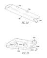
As shown in FIGS. 18A and 18B , anchors 190,1000, which are more clearly shown in FIGS. 19 and 20 , are coupled to the distal portion 182 b of the needle 182. Both anchors 190,1000 include holes 190 a,1000 a and slots 190 b,1000 b. The second anchor 1000 includes channels 1000 c on opposite sides of the anchor 1000 and a protrusion 1010. The second anchor 1000 is coupled to the needle 182, such that the sides 182 f of the slot 182 b″ are housed within the channels 1000 c and the back portion 182 e of the slot 182 b″ is within slot 1000 b. Also shown in FIGS. 18A-18B is a cannulated, transparent tube 200. The tube 200 includes a proximal portion 200 a, which is disposed over the distal portion 181 b of the rod 181 such that the flange 181 b′ engages an inner wall 200 c of the tube 200, and a distal portion 200 b is disposed over the protrusion 1010 of the second anchor 1000. The protrusion 1010 allows for an increased amount of interference between the distal portion 200 b of the tube 200 and the anchor 1000 when the distal portion 200 b is disposed over the protrusion 1010 of the anchor 100. This increased amount of interference increases the retention of the anchor 1000 to the needle 182.
The actuator 142 is disposed within needle 182 such that the end portion 142 b′″ of the actuator 142 is located proximal to the first anchor 190 and distal to the second anchor 1000.
As shown in FIG. 24A , the anchors 190,1000 are coupled via a flexible member 500, such as a suture, that includes a slip knot 501 located between the anchors 190,1000. The suture 500 is coupled to the anchors 190,1000 and the slip knot 501 is formed via the methods described in the above incorporated US patents and published applications. A free end 502 extends from the slip knot 501 and the suture length between the anchors 190,1000 is reduced upon pulling the free end 502 in one direction, but not in another direction, as will be further described below.
Referring to FIGS. 27-30 , in use, preferably under arthroscopic guidance, the user inserts the device 100 into, for example, the knee joint, until the beveled tip 182 b′ of the needle 182 is in contact with the superior surface of the meniscus 700, as shown in FIG. 27 . At this time, the device 100, and especially the starting position of its components, is as shown in FIGS. 24B-24D . Namely, as stated above, the end portion 142 b′″ of the actuator 142 is located proximal to the first anchor 190 and distal to the second anchor 1000 and a distal portion 200 b of the tube 200 is disposed over at least a portion of the second anchor 1000. The first portions 171, 172 a of the hub 170, and specifically the fronts (FIG. 22A, 171 a″,172 a″) of portions 171 a,172 a are aligned with the markings 300 d of the second portion 300 b. Similarly, as can be seen in FIG. 27 , the front 300 a′ of the depth tube 300 is aligned with the markings 182 b′″ of the needle 182. During repair, as the depth tube 300 is moved longitudinally along the needle 182, the fronts 171 a″, 172 a″, 300 a′ of the hub 170 and the depth tube 300 will continue to align with the markings 300 d, 182 b′″ such that the markings 300 d, 182 b′″ that the fronts 171 a″, 172 a″, 300 a′ are aligned with will be equivalent to each other. For example, when fronts 171 a″, 172 a″ are aligned with marking 300 d that corresponds to 1 mm, front 300 a′ is aligned marking 182 b′″ that corresponds with 1 mm.
Optionally, the depth tube 300 is disposed over the needle assembly 180 and, after insertion of the device 100 into the joint, the tube 300 is moved proximally, in a manner as described above, toward the knob 120 to uncover the distal end 182 b of the needle 182, and determine the appropriate needle insertion depth, which the laser marks 182 b′″, 300 d may be used for. In practice, enough of the needle 182 should be exposed to allow for insertion of the needle 182 through the meniscus and subsequent delivery of the anchor 190, but not so much that the needle 182 will extend into areas behind the meniscus, such as neurovascular areas, where it could cause damage.
In addition to the starting position of the beveled tip 182 b′ of the needle 182, the starting position of the disk 160 is shown in FIG. 24D . The disk 160 is located such that the protrusions 166 are located in slots 132 b, specifically region 132 b′, and the spikes 163 a of the protrusions 166 rest against stepped region 132 b′″.
Insertion of the end 182 b through the meniscus 700 occurs until the depth tube 300 prevents the needle 182 from being inserted any further or the user decides to discontinue insertion of the needle 182. The knob 120 is then moved distally over the hub 170 to deploy the first anchor 190, as shown in FIG. 28 . At this time, the position of the pusher disk 160 is shown in FIG. 25 . Specifically, movement of the knob 120 in a distal direction pushes the disk 160 out of slot 132 b. In addition, knob movement causes engagement to occur between spikes 163 a of disk 160 and spikes 121 e″ of rod 121 d″, thereby causing the disk 160 to partially rotate. After deployment of the first anchor 190, the knob 120 is moved proximally toward the handle 110. Upon movement of the knob 120 in a proximal direction, the protrusions 166 of the knob 120 engage the rails 139, which cause another partial rotation of the disk 160, thereby locating the protrusions 166 in slots 132 c. Once the protrusions 166 are located in slots 132 c, the disk 160 continues to move in the proximal direction until the head 122 of the knob 120 rests against the handle 110, as shown in FIG. 26A . FIG. 26A also shows the back portion 163 of the disk 160 resting against the face 121 e′ of the rod 121 d″. As shown in FIG. 26B , when the disk 160 is positioned as shown in FIG. 26A , the end portion 142 b′″ of the actuator 142 is located proximal to the second anchor 1000.
Once the first anchor 190 has been deployed, the needle 182 is removed from the meniscus 700 and re-inserted across the tear 701, as shown in FIG. 29 . The knob 120 is, once again, moved distally over the hub 170 to deploy the second anchor 1000. Specifically, when the end portion 142 b′″ of the actuator 142 is located proximal to the second anchor 1000, the end portion 142 b′″ is flipped upward, as shown in FIG. 26B , which allows the end portion 142 b′″ to engage the anchor 1000 and be inserted into the slot 1000 b upon movement of the knob 120 in a distal direction. Further movement of the actuator 142 pushes the anchor 1000 out of the needle 182. In addition, knob movement in a distal direction causes the disk 160 to be dispelled from the slot 132 b, thereby causing the disk 160 to partially rotate. After deployment of the second anchor 1000, the knob 120 is moved proximally toward the handle 110. Upon movement of the knob 120 in a proximal direction, the protrusions 166 of the disk 160 engage the rails 139, which cause another partial rotation of the disk 160, thereby locating the protrusions 166 in slots 132 b. Once the protrusions 166 are located in slots 132 b, the disk 160 continues to move in the proximal direction until the spikes 163 a of the protrusions 166, once again, rest against stepped region 132 b′″, as shown in FIG. 24D .
The device 10 is subsequently removed from the knee joint and the free end 502 is pulled in the direction of arrow 600. This shortens the length of suture between anchors 190,1000, bringing sides of tear 701 into juxtaposition, as shown in FIG. 30 . Depending on the length of suture between anchors 190,1000, the slip knot 501 will either be on the tissue surface or move within the tissue 700. Slip knot 501 allows the suture 500 to slide in the direction of arrow 601, but does not allow the suture 500 to slide in the opposite direction 600. The tension placed on suture 500 by pulling on the suture 500 relative to anchors 190,1000 acts to turn the anchors 190,1000 such that their long sides are in contact with tissue surface. Excess suture 500 can then be cut off. Further manipulation of suture 500 is not needed to secure anchors 190,1000, although the surgeon may wish to provide additional fastening as a back-up securement measure.
For the purposes of this disclosure, the needle 182, rod 181, actuator 142, and spring 150 are of a biocompatible metal material, such as stainless steel, but may be made from a non-metal material. All of the other components are made from a non-metal material. The anchors 190,1000 and suture 500 are of a polymer material, which may or may not be an absorbable polymer material. The actuator 142 may be coupled to the shaft 141 and the needle 182 may be coupled to the rod 181 via mechanical means, adhesive means, such as a non-toxic, biocompatible, adhesive glue, or other means known to one of skill in the art. The device 100 and its components are all made via a method known to one of skill in the art, including, but not limited to injection molding.
As various modifications could be made to the exemplary embodiments, as described above with reference to the corresponding illustrations, without departing from the scope of the disclosure, it is intended that all matter contained in the foregoing description and shown in the accompanying drawings shall be interpreted as illustrative rather than limiting. Thus, the breadth and scope of the present disclosure should not be limited by any of the above-described exemplary embodiments, but should be defined only in accordance with the following claims appended hereto and their equivalents.
Claims (25)
1. A tissue repair device comprising:
a handle;
a cannula coupled to the handle, the cannula having a central axis; and
a user control configured for actuating a spring-loaded pusher assembly housed within the handle that is not attached to the user control, the pusher assembly comprising a shaft, a coiled spring and an actuator coupled to the shaft, the shaft including a proximal portion and a distal portion, the proximal portion of shaft including a flat portion, the distal portion of the shaft including a cap and an inner channel, an end of the coiled spring resting against the cap, the pusher assembly configured to push the actuator disposed within the cannula for delivery of a flexible member to secure the tissue;
a first anchor coupled with the flexible member, and disposed entirely within the cannula for deployment along a first deployment path;
a knot disposed in the flexible member that is coupled to a second anchor, the second anchor disposed at least partially offset with respect to the central axis of the cannula and configured to deploy along a second deployment path distinct from the first deployment path;
wherein the pusher assembly is configured to reciprocate between a first position in which the first anchor is engaged with the pusher assembly and upon return to which the second anchor is successively engaged with the pusher assembly, and a second position wherein the first anchor and the second anchor are successively expelled from the cannula after traversing their respective deployment paths.
2. The tissue repair device of claim 1 , wherein at least a portion of the user control is slidably disposed along an exterior side of the handle and is configurable to initiate the delivery of the flexible member.
3. The tissue repair device of claim 1 , further comprising a hub for retaining the actuator.
4. The tissue repair device of claim 1 , further comprising a depth indicator configurable for coupling with the cannula.
5. The tissue repair device of claim 4 , wherein the depth indicator is configured to limit insertion depth of a needle into the tissue.
6. The tissue repair device of claim 1 , further comprising a needle disposed within the cannula and coupled to the actuator.
7. The tissue repair device of claim 6 , wherein a distal top of the needle is configured for insertion into the tissue.
8. The tissue repair device of claim 6 , wherein the needle is configured for retaining an anchor coupled to the flexible member.
9. The tissue repair device of claim 6 , wherein the actuator is configured for deploying an anchor from a distal end of the needle.
10. The tissue repair device of claim 1 , wherein the pusher assembly comprises apparatus for deploying an anchor.
11. The tissue repair device of claim 10 , wherein the pusher assembly is controlled by a user-moveable device.
12. The tissue repair device of claim 1 , wherein at least one component thereof comprises at least one of a metal material, a polymer material, and a biocompatible material.
13. The tissue repair device of claim 1 , wherein at least one the flexible member and an anchor for anchoring the flexible member comprise absorbable material.
14. The tissue repair device of claim 1 , wherein the spring-loaded pusher assembly is biased in a direction opposite to a direction of the delivery.
15. The tissue repair device of claim 1 , wherein the user control comprises a knob.
16. The tissue repair device of claim 1 , wherein at least one of the first anchor or the second anchor includes a proximal end for releasably mating with a distal end of the actuator.
17. The tissue repair device of claim 1 , wherein the knot comprises a slip knot.
18. A tissue repair device comprising:
a handle defining a cavity,
a user control configured for actuating a pusher assembly that is not attached to the user control;
a cannula coupled to the handle;
a needle disposed within the cannula, the needle having a central longitudinal axis;
a first anchor disposed entirely within the needle for deployment along a first deployment path; and
a second anchor disposed at least partially offset with respect to the central longitudinal axis of the needle and configured to deploy along a second deployment path distinct from the first deployment path;
wherein the pusher assembly comprises a shaft, a coiled spring and an actuator coupled to the shaft, the shaft including a proximal portion and a distal portion, the proximal portion of the shaft including a flat portion, the distal portion of the shaft including a cap and an inner channel, an end of the coiled spring resting against the cap, the pusher assembly being housed within the cavity, the pusher assembly configured to push the actuator within the needle for delivery of a flexible member provided to secure the tissue, the flexible member coupled with the first anchor and the second anchor with a knot between the first and second anchor, wherein at least one of the first anchor and the second anchor are at least partially offset with respect to a central axis of the needle; and
wherein the pusher assembly is configured to reciprocate between a first position in which the first anchor is engaged with the pusher assembly and upon return to which the second anchor is successively engaged with the pusher assembly, and a second position wherein the first anchor and the second anchor are successively expelled from the cannula after traversing their respective deployment paths.
19. The tissue repair device of claim 18 , wherein at least one of the first anchor or the second anchor includes a proximal end for releasably mating with a distal end of the actuator.
20. A tissue repair device, comprising:
a handle;
a cannula having a central axis and coupled to the handle;
a needle disposed within the cannula, the needle including a proximal end and a distal end, wherein a first anchor is disposed entirely within the cannula and coupled to a flexible member, and a second anchor is disposed at least partially offset with respect to the central axis of the cannula are disposed within the needle and at least one of the first anchor and the second anchor are at least partially offset with respect to a central axis of the needle;
an actuator disposed within the cannula operatively coupled to the first anchor;
an actuator advancement mechanism operatively coupled to the actuator and spring-biased towards a first position in which the first anchor is not deployed;
wherein displacement of the actuator advancement mechanism to a second position allows for engagement of the actuator with the first anchor such that the first anchor is displaced from the needle in a distal direction along a first deployment path;
wherein subsequent return of the actuator advancement mechanism back to the first position permits engagement of the actuator to the second anchor; and
wherein displacement of the actuator advancement mechanism again to the second position allows for displacement of the second anchor from the needle in the distal direction along a second deployment path distinct from the first deployment path.
21. The tissue repair device of claim 20 , further comprising a flexible member coupling the first anchor to the second anchor and including a cinchable knot.
22. The tissue repair device of claim 20 , further comprising a depth indicator configurable for coupling with the cannula.
23. The tissue repair device of claim 22 , wherein the depth indicator is configured to limit insertion depth of the needle into the tissue.
24. The tissue repair device of claim 20 , wherein at least one of the first anchor or the second anchor includes a proximal end for releasably mating with a distal end of the actuator.
25. A method of repairing tissue, the method comprising:
selecting a tissue repair device comprising:
a handle;
a cannula coupled to the handle, the cannula having a central longitudinal axis;
a first anchor disposed entirely within the cannula and coupled to a flexible member, the first anchor having a first deployment path;
a second anchor disposed at least partially in the cannula offset with respect to the central longitudinal axis of the cannula and coupled to the flexible member, the flexible member including a knot between the first anchor and the second anchor, the second anchor having a second deployment path distinct from the first deployment path; and
a spring-loaded pusher assembly comprising a shaft, a coiled spring and an actuator coupled to the shaft, the shaft including a proximal portion and a distal portion, the proximal portion of the shaft including a flat portion, the distal portion of the shaft including a cap and an inner channel, an end of the coiled spring resting against the cap, the pusher assembly housed within the handle, the pusher assembly configured to reciprocate between a first position in which the first anchor is engaged with the pusher assembly and upon return to which the second anchor is engaged with the pusher assembly, and a second position wherein the first anchor and the second anchor are successively expelled from the cannula for delivery of the flexible member to secure the tissue;
delivering the first anchor to a side of a tissue tear in the tissue via use of the tissue repair device by controlling a user control that is not attached to the pusher assembly, the user control on the handle configured to reposition the spring-loaded pusher assembly to the second position, thereby pushing the first anchor along the first deployment path and expelling the first anchor from the cannula;
repositioning the spring-loaded pusher assembly to the first position;
engaging the second anchor and the spring-loaded pusher assembly;
delivering the second anchor to the tissue on an opposite side of the tissue tear by repositioning the spring-loaded pusher assembly to the second position, thereby pushing the second anchor along the second deployment path and expelling the second anchor from the cannula; and
applying a compressive force to the tissue tear by tightening the slip knot between the first anchor and the second anchor.
Priority Applications (1)
| Application Number | Priority Date | Filing Date | Title |
|---|---|---|---|
| US14/272,817 US9498203B2 (en) | 2008-11-26 | 2014-05-08 | Tissue repair device |
Applications Claiming Priority (6)
| Application Number | Priority Date | Filing Date | Title |
|---|---|---|---|
| US11798708P | 2008-11-26 | 2008-11-26 | |
| US16690709P | 2009-04-06 | 2009-04-06 | |
| US25599509P | 2009-10-29 | 2009-10-29 | |
| US12/623,930 US8888798B2 (en) | 2008-11-26 | 2009-11-23 | Tissue repair device |
| US14/242,171 US9549725B2 (en) | 2008-11-26 | 2014-04-01 | Tissue repair device |
| US14/272,817 US9498203B2 (en) | 2008-11-26 | 2014-05-08 | Tissue repair device |
Related Parent Applications (1)
| Application Number | Title | Priority Date | Filing Date |
|---|---|---|---|
| US14/242,171 Continuation US9549725B2 (en) | 2008-11-26 | 2014-04-01 | Tissue repair device |
Publications (2)
| Publication Number | Publication Date |
|---|---|
| US20140243858A1 US20140243858A1 (en) | 2014-08-28 |
| US9498203B2 true US9498203B2 (en) | 2016-11-22 |
Family
ID=41465145
Family Applications (8)
| Application Number | Title | Priority Date | Filing Date |
|---|---|---|---|
| US12/623,930 Active 2031-05-06 US8888798B2 (en) | 2008-11-26 | 2009-11-23 | Tissue repair device |
| US14/242,171 Active 2030-06-22 US9549725B2 (en) | 2008-11-26 | 2014-04-01 | Tissue repair device |
| US14/272,817 Active US9498203B2 (en) | 2008-11-26 | 2014-05-08 | Tissue repair device |
| US14/504,353 Active US9357994B2 (en) | 2008-11-26 | 2014-10-01 | Tissue repair device |
| US15/391,287 Active 2030-12-20 US10390815B2 (en) | 2008-11-26 | 2016-12-27 | Tissue repair device |
| US16/506,181 Active 2030-10-13 US11179148B2 (en) | 2008-11-26 | 2019-07-09 | Tissue repair device |
| US16/681,184 Active US10695050B2 (en) | 2008-11-26 | 2019-11-12 | Tissue repair device |
| US17/483,887 Pending US20220008062A1 (en) | 2008-11-26 | 2021-09-24 | Tissue repair device |
Family Applications Before (2)
| Application Number | Title | Priority Date | Filing Date |
|---|---|---|---|
| US12/623,930 Active 2031-05-06 US8888798B2 (en) | 2008-11-26 | 2009-11-23 | Tissue repair device |
| US14/242,171 Active 2030-06-22 US9549725B2 (en) | 2008-11-26 | 2014-04-01 | Tissue repair device |
Family Applications After (5)
| Application Number | Title | Priority Date | Filing Date |
|---|---|---|---|
| US14/504,353 Active US9357994B2 (en) | 2008-11-26 | 2014-10-01 | Tissue repair device |
| US15/391,287 Active 2030-12-20 US10390815B2 (en) | 2008-11-26 | 2016-12-27 | Tissue repair device |
| US16/506,181 Active 2030-10-13 US11179148B2 (en) | 2008-11-26 | 2019-07-09 | Tissue repair device |
| US16/681,184 Active US10695050B2 (en) | 2008-11-26 | 2019-11-12 | Tissue repair device |
| US17/483,887 Pending US20220008062A1 (en) | 2008-11-26 | 2021-09-24 | Tissue repair device |
Country Status (6)
| Country | Link |
|---|---|
| US (8) | US8888798B2 (en) |
| EP (1) | EP2369999B1 (en) |
| JP (2) | JP5579736B2 (en) |
| CN (3) | CN103705281B (en) |
| AU (2) | AU2009319897B2 (en) |
| WO (1) | WO2010062851A1 (en) |
Cited By (1)
| Publication number | Priority date | Publication date | Assignee | Title |
|---|---|---|---|---|
| WO2019102484A1 (en) | 2017-11-27 | 2019-05-31 | T.A.G. Medical Devices - Agriculture Cooperative Ltd. | Multiple anchor delivery system and method |
Families Citing this family (95)
| Publication number | Priority date | Publication date | Assignee | Title |
|---|---|---|---|---|
| EP3097865B1 (en) | 2005-02-07 | 2020-01-08 | Ivy Sports Medicine, LLC. | System for all-inside suture fixation for implant attachment and soft tissue repair |
| US8128640B2 (en) | 2005-02-07 | 2012-03-06 | Ivy Sports Medicine LLC | System and method for all-inside suture fixation for implant attachment and soft tissue repair |
| WO2006097931A2 (en) | 2005-03-17 | 2006-09-21 | Valtech Cardio, Ltd. | Mitral valve treatment techniques |
| US11259924B2 (en) | 2006-12-05 | 2022-03-01 | Valtech Cardio Ltd. | Implantation of repair devices in the heart |
| US9883943B2 (en) | 2006-12-05 | 2018-02-06 | Valtech Cardio, Ltd. | Implantation of repair devices in the heart |
| US11660190B2 (en) | 2007-03-13 | 2023-05-30 | Edwards Lifesciences Corporation | Tissue anchors, systems and methods, and devices |
| US8382829B1 (en) | 2008-03-10 | 2013-02-26 | Mitralign, Inc. | Method to reduce mitral regurgitation by cinching the commissure of the mitral valve |
| CN103705281B (en) * | 2008-11-26 | 2017-04-26 | 史密夫和内修有限公司 | Tissue repair device |
| EP2375995A1 (en) | 2008-12-15 | 2011-10-19 | Smith & Nephew, Inc. | Composite anchor |
| US10517719B2 (en) | 2008-12-22 | 2019-12-31 | Valtech Cardio, Ltd. | Implantation of repair devices in the heart |
| WO2010073246A2 (en) | 2008-12-22 | 2010-07-01 | Valtech Cardio, Ltd. | Adjustable annuloplasty devices and adjustment mechanisms therefor |
| US8545553B2 (en) | 2009-05-04 | 2013-10-01 | Valtech Cardio, Ltd. | Over-wire rotation tool |
| US8241351B2 (en) | 2008-12-22 | 2012-08-14 | Valtech Cardio, Ltd. | Adjustable partial annuloplasty ring and mechanism therefor |
| US8715342B2 (en) * | 2009-05-07 | 2014-05-06 | Valtech Cardio, Ltd. | Annuloplasty ring with intra-ring anchoring |
| US8353956B2 (en) | 2009-02-17 | 2013-01-15 | Valtech Cardio, Ltd. | Actively-engageable movement-restriction mechanism for use with an annuloplasty structure |
| US9968452B2 (en) | 2009-05-04 | 2018-05-15 | Valtech Cardio, Ltd. | Annuloplasty ring delivery cathethers |
| US9180007B2 (en) | 2009-10-29 | 2015-11-10 | Valtech Cardio, Ltd. | Apparatus and method for guide-wire based advancement of an adjustable implant |
| US10098737B2 (en) | 2009-10-29 | 2018-10-16 | Valtech Cardio, Ltd. | Tissue anchor for annuloplasty device |
| WO2011067770A1 (en) | 2009-12-02 | 2011-06-09 | Valtech Cardio, Ltd. | Delivery tool for implantation of spool assembly coupled to a helical anchor |
| EP2433571B1 (en) * | 2010-09-23 | 2022-09-28 | Tornier, Inc. | System for bone anchor inserter depth indication |
| US8795334B2 (en) | 2011-01-28 | 2014-08-05 | Smith & Nephew, Inc. | Tissue repair |
| JP5989759B2 (en) * | 2011-03-22 | 2016-09-07 | スミス アンド ネフュー インコーポレーテッド | Mooring system and feeding device for use with the mooring system |
| US8858623B2 (en) | 2011-11-04 | 2014-10-14 | Valtech Cardio, Ltd. | Implant having multiple rotational assemblies |
| EP3656434B1 (en) | 2011-11-08 | 2021-10-20 | Valtech Cardio, Ltd. | Controlled steering functionality for implant-delivery tool |
| US9084597B2 (en) | 2012-03-09 | 2015-07-21 | Smith & Nephew, Inc. | Suture-based knotless repair |
| US9433456B2 (en) * | 2012-07-18 | 2016-09-06 | Jmea Corporation | Method and system for implanting multiple prostheses |
| WO2014052818A1 (en) | 2012-09-29 | 2014-04-03 | Mitralign, Inc. | Plication lock delivery system and method of use thereof |
| US8986327B2 (en) | 2012-10-18 | 2015-03-24 | Smith & Nephew, Inc. | Flexible anchor delivery system |
| EP3730084A1 (en) | 2012-10-23 | 2020-10-28 | Valtech Cardio, Ltd. | Controlled steering functionality for implant-delivery tool |
| WO2014064695A2 (en) | 2012-10-23 | 2014-05-01 | Valtech Cardio, Ltd. | Percutaneous tissue anchor techniques |
| WO2014087402A1 (en) | 2012-12-06 | 2014-06-12 | Valtech Cardio, Ltd. | Techniques for guide-wire based advancement of a tool |
| US9801624B2 (en) * | 2012-12-28 | 2017-10-31 | Cook Medical Technologies Llc | Surgical suture device and methods of using the same |
| US9724084B2 (en) | 2013-02-26 | 2017-08-08 | Mitralign, Inc. | Devices and methods for percutaneous tricuspid valve repair |
| CN105188562B (en) | 2013-03-06 | 2019-02-26 | 史密夫和内修有限公司 | Miniature anchor |
| US10449333B2 (en) | 2013-03-14 | 2019-10-22 | Valtech Cardio, Ltd. | Guidewire feeder |
| CN105283214B (en) | 2013-03-15 | 2018-10-16 | 北京泰德制药股份有限公司 | Translate conduit, system and its application method |
| GB2513156A (en) * | 2013-04-17 | 2014-10-22 | Neosurgical Ltd | Delivery system |
| US10070857B2 (en) | 2013-08-31 | 2018-09-11 | Mitralign, Inc. | Devices and methods for locating and implanting tissue anchors at mitral valve commissure |
| US10299793B2 (en) | 2013-10-23 | 2019-05-28 | Valtech Cardio, Ltd. | Anchor magazine |
| US9522000B2 (en) * | 2013-11-08 | 2016-12-20 | Coloplast A/S | System and a method for surgical suture fixation |
| US9610162B2 (en) | 2013-12-26 | 2017-04-04 | Valtech Cardio, Ltd. | Implantation of flexible implant |
| US10914902B2 (en) * | 2014-02-26 | 2021-02-09 | TeraDiode, Inc. | Methods for altering properties of a radiation beam |
| US9861728B2 (en) | 2014-05-20 | 2018-01-09 | Circulite, Inc. | Heart assist system and methods |
| WO2016059639A1 (en) | 2014-10-14 | 2016-04-21 | Valtech Cardio Ltd. | Leaflet-restraining techniques |
| JP2017531509A (en) * | 2014-10-15 | 2017-10-26 | スミス アンド ネフュー インコーポレイテッド | Arthroscopic meniscal tear repair device |
| US10034742B2 (en) * | 2014-10-23 | 2018-07-31 | Medos International Sarl | Biceps tenodesis implants and delivery tools |
| US10856966B2 (en) | 2014-10-23 | 2020-12-08 | Medos International Sarl | Biceps tenodesis implants and delivery tools |
| US10729419B2 (en) | 2014-10-23 | 2020-08-04 | Medos International Sarl | Biceps tenodesis implants and delivery tools |
| US10076374B2 (en) | 2014-10-23 | 2018-09-18 | Medos International Sárl | Biceps tenodesis delivery tools |
| US10751161B2 (en) | 2014-10-23 | 2020-08-25 | Medos International Sárl | Biceps tenodesis anchor implants |
| JP6461336B2 (en) * | 2014-10-29 | 2019-01-30 | スミス アンド ネフュー インコーポレイテッド | Modular tissue repair kit and related devices and methods |
| US9687223B2 (en) | 2014-12-04 | 2017-06-27 | Coloplast A/S | Tissue anchor system |
| US10499904B2 (en) * | 2015-02-17 | 2019-12-10 | Smith & Nephew, Inc. | Anchor insertion system and method of use thereof |
| US20160256269A1 (en) | 2015-03-05 | 2016-09-08 | Mitralign, Inc. | Devices for treating paravalvular leakage and methods use thereof |
| US9693856B2 (en) | 2015-04-22 | 2017-07-04 | DePuy Synthes Products, LLC | Biceps repair device |
| CN114515173A (en) | 2015-04-30 | 2022-05-20 | 瓦尔泰克卡迪欧有限公司 | Valvuloplasty techniques |
| CA3005616A1 (en) | 2015-12-04 | 2017-06-08 | First Ray, LLC | Devices for anchoring tissue |
| WO2017117370A2 (en) | 2015-12-30 | 2017-07-06 | Mitralign, Inc. | System and method for reducing tricuspid regurgitation |
| US10231824B2 (en) * | 2016-04-08 | 2019-03-19 | Medos International Sárl | Tenodesis anchoring systems and tools |
| US10231823B2 (en) | 2016-04-08 | 2019-03-19 | Medos International Sarl | Tenodesis implants and tools |
| US10238444B2 (en) * | 2016-05-10 | 2019-03-26 | DePuy Synthes Products, Inc. | Insertion tool for flip anchor cable system insertion |
| US10932769B2 (en) * | 2016-05-26 | 2021-03-02 | Ivy Sports Medicine, Llc | System and method for all-inside suture fixation for implant attachment and soft tissue repair |
| US10702274B2 (en) | 2016-05-26 | 2020-07-07 | Edwards Lifesciences Corporation | Method and system for closing left atrial appendage |
| GB201611910D0 (en) | 2016-07-08 | 2016-08-24 | Valtech Cardio Ltd | Adjustable annuloplasty device with alternating peaks and troughs |
| CN105943101A (en) * | 2016-07-18 | 2016-09-21 | 黄明 | Puncture hole suturing device for minimally invasive surgery |
| CN105997212B (en) * | 2016-07-26 | 2018-12-18 | 上海市同济医院 | Anterior cruciate ligament depends on avulsion fracture and punctures fixed wire-threading device |
| EP3506839A1 (en) * | 2016-08-31 | 2019-07-10 | Smith & Nephew, Inc. | Articulated meniscal repair instrument |
| US10743859B2 (en) * | 2016-10-21 | 2020-08-18 | Covidien Lp | Surgical end effectors |
| WO2018081045A1 (en) * | 2016-10-27 | 2018-05-03 | Smith & Nephew, Inc. | Tissue repair device |
| US11452516B2 (en) * | 2016-11-03 | 2022-09-27 | Smith & Nephew, Inc. | Tissue repair assembly and system with soft anchoring implant |
| CN107625540A (en) * | 2017-04-01 | 2018-01-26 | 北京万洁天元医疗器械有限公司 | A kind of complete interior stitching devices of tissue repair |
| US11045627B2 (en) | 2017-04-18 | 2021-06-29 | Edwards Lifesciences Corporation | Catheter system with linear actuation control mechanism |
| CN107822743A (en) * | 2017-10-20 | 2018-03-23 | 北京迈迪顶峰医疗科技有限公司 | A kind of system that leaflet reparation is carried out for Minimally Invasive Surgery |
| US10835221B2 (en) | 2017-11-02 | 2020-11-17 | Valtech Cardio, Ltd. | Implant-cinching devices and systems |
| US11135062B2 (en) | 2017-11-20 | 2021-10-05 | Valtech Cardio Ltd. | Cinching of dilated heart muscle |
| CN116531147A (en) | 2018-01-24 | 2023-08-04 | 爱德华兹生命科学创新(以色列)有限公司 | Contraction of annuloplasty structures |
| EP3743014B1 (en) | 2018-01-26 | 2023-07-19 | Edwards Lifesciences Innovation (Israel) Ltd. | Techniques for facilitating heart valve tethering and chord replacement |
| CN108523953B (en) * | 2018-04-17 | 2021-02-23 | 四川大学华西医院 | Ware is sewed up to a stitch first line meniscus |
| EP3793453B1 (en) * | 2018-05-17 | 2024-01-10 | Smith&Nephew, Inc. | Tissue repair device |
| US10631850B2 (en) * | 2018-05-23 | 2020-04-28 | Smith & Nephew, Inc. | Axially-complaint driver assembly |
| CN112638282A (en) * | 2018-05-29 | 2021-04-09 | 史密夫和内修有限公司 | Suture passer with locking actuator |
| CR20210020A (en) | 2018-07-12 | 2021-07-21 | Valtech Cardio Ltd | Annuloplasty systems and locking tools therefor |
| US11064995B2 (en) | 2019-05-02 | 2021-07-20 | Arthrex, Inc. | Surgical device with trigger operated needle |
| EP3738519A1 (en) * | 2019-05-13 | 2020-11-18 | Smith & Nephew, Inc. | Anchor delivery systems |
| CA3145655A1 (en) * | 2019-07-02 | 2021-01-07 | Arthrex, Inc. | Tissue repair device |
| WO2021038474A1 (en) | 2019-08-26 | 2021-03-04 | Janssen Biotech, Inc. | Tissue anchor and related methods |
| CA3142906A1 (en) | 2019-10-29 | 2021-05-06 | Valtech Cardio, Ltd. | Annuloplasty and tissue anchor technologies |
| US20230014258A1 (en) * | 2019-12-19 | 2023-01-19 | LMF Industries Pty Ltd | Device for meniscal repair |
| EP4120924A1 (en) | 2020-03-16 | 2023-01-25 | Smith & Nephew, Inc. | Depth penetration limiter for a tissue repair device |
| US20230134233A1 (en) | 2020-04-08 | 2023-05-04 | Smith & Nephew, Inc. | Meniscal repair delivery device |
| EP3903692A1 (en) | 2020-04-29 | 2021-11-03 | Coloplast A/S | A tissue anchor system including a fixation device and a delivery tool |
| USD980424S1 (en) | 2020-04-29 | 2023-03-07 | Coloplast A/S | Tissue anchor |
| CN112089456A (en) * | 2020-08-19 | 2020-12-18 | 广州医科大学附属第五医院 | Surgical suture instrument |
| WO2023121935A1 (en) | 2021-12-20 | 2023-06-29 | Smith & Nephew, Inc. | Tissue repair devices and methods of use |
| CN116421241B (en) * | 2023-06-08 | 2023-08-22 | 北京万洁天元医疗器械股份有限公司 | Meniscus injury repair device |
Citations (59)
| Publication number | Priority date | Publication date | Assignee | Title |
|---|---|---|---|---|
| US312199A (en) | 1885-02-10 | ginter | ||
| US2222125A (en) | 1940-03-19 | 1940-11-19 | Rudolph J Stehlik | Nail driver |
| US4235238A (en) | 1978-05-11 | 1980-11-25 | Olympus Optical Co., Ltd. | Apparatus for suturing coeliac tissues |
| US5041129A (en) | 1990-07-02 | 1991-08-20 | Acufex Microsurgical, Inc. | Slotted suture anchor and method of anchoring a suture |
| US5176691A (en) | 1990-09-11 | 1993-01-05 | Pierce Instruments, Inc. | Knot pusher |
| US5234447A (en) | 1990-08-28 | 1993-08-10 | Robert L. Kaster | Side-to-end vascular anastomotic staple apparatus |
| US5269809A (en) | 1990-07-02 | 1993-12-14 | American Cyanamid Company | Locking mechanism for use with a slotted suture anchor |
| US5376097A (en) | 1991-04-05 | 1994-12-27 | Phillips; Edward H. | Surgical fastener system |
| US5454824A (en) | 1992-10-09 | 1995-10-03 | United States Surgical Corporation | Fragmentable ring applier |
| US5470337A (en) | 1994-05-17 | 1995-11-28 | Moss; Gerald | Surgical fastener |
| US5522845A (en) | 1994-09-27 | 1996-06-04 | Mitek Surgical Products, Inc. | Bone anchor and bone anchor installation |
| US5601571A (en) | 1994-05-17 | 1997-02-11 | Moss; Gerald | Surgical fastener implantation device |
| US5810848A (en) | 1996-08-21 | 1998-09-22 | Hayhurst; John O. | Suturing system |
| US5928252A (en) | 1997-01-21 | 1999-07-27 | Regen Biologics, Inc. | Device and method for driving a needle and meniscal repair |
| US5948002A (en) | 1996-11-15 | 1999-09-07 | Bonutti; Peter M. | Apparatus and method for use in positioning a suture anchor |
| US6059799A (en) | 1998-06-25 | 2000-05-09 | United States Surgical Corporation | Apparatus for applying surgical clips |
| US6071292A (en) | 1997-06-28 | 2000-06-06 | Transvascular, Inc. | Transluminal methods and devices for closing, forming attachments to, and/or forming anastomotic junctions in, luminal anatomical structures |
| WO2001039671A1 (en) | 1999-12-02 | 2001-06-07 | Smith & Nephew, Inc. | Wound closure devices and methods |
| US6306159B1 (en) | 1998-12-23 | 2001-10-23 | Depuy Orthopaedics, Inc. | Meniscal repair device |
| US6319271B1 (en) | 1998-12-30 | 2001-11-20 | Depuy Orthopaedics, Inc. | Suture locking device |
| WO2002036020A1 (en) | 2000-11-02 | 2002-05-10 | Smith & Nephew, Inc. | Closure device and method for tissue repair |
| US6554845B1 (en) | 2000-09-15 | 2003-04-29 | PARÉ Surgical, Inc. | Suturing apparatus and method |
| US20030130694A1 (en) | 1999-12-02 | 2003-07-10 | Ray Bojarski | Soft tissue attachment and repair |
| US20030139754A1 (en) | 2002-01-23 | 2003-07-24 | Reinhold Schmieding | Meniscal repair system and method |
| US6736829B1 (en) | 1999-11-11 | 2004-05-18 | Linvatec Corporation | Toggle anchor and tool for insertion thereof |
| US20040138683A1 (en) * | 2003-01-09 | 2004-07-15 | Walter Shelton | Suture arrow device and method of using |
| US6767037B2 (en) | 2001-09-27 | 2004-07-27 | Depuy Mitek, Inc. | Sliding and locking surgical knot |
| US20040220573A1 (en) * | 1999-07-23 | 2004-11-04 | Ethicon, Inc. | System and method for attaching soft tissue to bone |
| US20040249392A1 (en) | 2003-06-06 | 2004-12-09 | Olympus Corporation | Anastomosing instrument |
| US6972027B2 (en) | 2002-06-26 | 2005-12-06 | Stryker Endoscopy | Soft tissue repair system |
| US20050283192A1 (en) * | 1999-12-02 | 2005-12-22 | Torrie Paul A | Closure device and method for tissue repair |
| US20050283246A1 (en) * | 1999-08-13 | 2005-12-22 | Cauthen Joseph C Iii | Method and apparatus for the treatment of the intervertebral disc annulus |
| US20060178680A1 (en) | 2005-02-07 | 2006-08-10 | Regen Biologics, Inc. | System and method for all-inside suture fixation for implant attachment and soft tissue repair |
| US20060190042A1 (en) | 2004-11-05 | 2006-08-24 | Arthrotek, Inc. | Tissue repair assembly |
| US20060293709A1 (en) | 2005-06-24 | 2006-12-28 | Bojarski Raymond A | Tissue repair device |
| US20070027476A1 (en) | 2005-02-07 | 2007-02-01 | Regen Biologics, Inc. | System and method for all-inside suture fixation for implant attachment and soft tissue repair |
| US20070073321A1 (en) | 2005-09-28 | 2007-03-29 | Olympus Medical Systems Corp. | Method for suturing perforation |
| US20070073316A1 (en) | 2001-11-20 | 2007-03-29 | Jean-Claude Sgro | Fastener for fixing a prosthesis, and device for delivering this fastener |
| US20070083236A1 (en) | 2005-06-24 | 2007-04-12 | Smith & Nephew, Inc. | Methods and devices for tissue repair |
| US20070185532A1 (en) * | 2006-02-03 | 2007-08-09 | Arthrotek, Inc. | Soft tissue repair assembly and associated method |
| US20070198032A1 (en) * | 2006-02-22 | 2007-08-23 | Ethicon Endo-Surgery, Inc. | Methods and devices for fastener removal |
| WO2007124773A1 (en) | 2006-04-28 | 2007-11-08 | Covidien Ag | Organopexy tool set |
| CN101094618A (en) | 2004-08-18 | 2007-12-26 | 斯坎迪乌斯生物医药公司 | Method and apparatus for reconstructing a ligament |
| US7320701B2 (en) | 2003-06-02 | 2008-01-22 | Linvatec Corporation | Push-in suture anchor, insertion tool, and method for inserting a push-in suture anchor |
| WO2008024911A2 (en) | 2006-08-25 | 2008-02-28 | Kyphon Sarl | Apparatus and methods for use of expandable members in surgical applications |
| US7390332B2 (en) | 2004-02-24 | 2008-06-24 | Depuy Mitek, Inc. | Methods and devices for repairing tissue |
| US20080177304A1 (en) | 2004-09-29 | 2008-07-24 | Usgi Medical, Inc. | Apparatus for grasping and cinching tissue anchors |
| US20080208218A1 (en) | 2007-02-27 | 2008-08-28 | Olympus Medical Systems Corp. | Suture tool |
| US7455683B2 (en) | 2004-02-26 | 2008-11-25 | Depuy Mitek, Inc. | Methods and devices for repairing triangular fibrocartilage complex tears |
| US7461574B2 (en) | 2003-04-28 | 2008-12-09 | Biomet Microfixation, Llc | Multiple screw delivery apparatus |
| US20090054928A1 (en) | 2004-11-05 | 2009-02-26 | Biomet Sports Medicine, Llc | Method and apparatus for coupling anatomical features |
| US20090069823A1 (en) | 2007-09-12 | 2009-03-12 | Foerster Seth A | Implant and delivery system for soft tissue repair |
| US20090088780A1 (en) | 2007-09-28 | 2009-04-02 | Olympus Medical Systems Corp. | Suturing device |
| US20090228042A1 (en) | 2008-03-04 | 2009-09-10 | Koogle Jr David C | Method and system for meniscal repair using suture implant cinch construct |
| US7608092B1 (en) | 2004-02-20 | 2009-10-27 | Biomet Sports Medicince, LLC | Method and apparatus for performing meniscus repair |
| US7771429B2 (en) | 2006-08-25 | 2010-08-10 | Warsaw Orthopedic, Inc. | Surgical tool for holding and inserting fasteners |
| US7867251B2 (en) | 2001-11-08 | 2011-01-11 | Smith & Nephew, Inc. | Reattachment of tissue to base tissue |
| US20110160768A1 (en) | 2006-02-03 | 2011-06-30 | Biomet Sports Medicine, Llc | Soft Tissue Repair Device and Associated Methods |
| JP2014075295A (en) | 2012-10-05 | 2014-04-24 | Japan Aviation Electronics Industry Ltd | Connector |
Family Cites Families (8)
| Publication number | Priority date | Publication date | Assignee | Title |
|---|---|---|---|---|
| US3656520A (en) * | 1970-03-30 | 1972-04-18 | Fmc Corp | Power tool and automatic feed therefor |
| US4936169A (en) * | 1988-07-25 | 1990-06-26 | Parsons Billy J | Device for positioning and applying fasteners |
| CA2224366C (en) * | 1996-12-11 | 2006-10-31 | Ethicon, Inc. | Meniscal repair device |
| US8632590B2 (en) * | 1999-10-20 | 2014-01-21 | Anulex Technologies, Inc. | Apparatus and methods for the treatment of the intervertebral disc |
| US20020188301A1 (en) * | 2001-06-11 | 2002-12-12 | Dallara Mark Douglas | Tissue anchor insertion system |
| US20080065120A1 (en) * | 2005-10-31 | 2008-03-13 | Zannis Anthony D | Surgical instrument, kit and method for creating mattress-type stitches |
| US7818281B2 (en) * | 2006-02-14 | 2010-10-19 | Affymetrix, Inc. | Computer software for visualizing recombination events in a group of individuals from recombination breakpoints and assignments in high density SNP genotyping data by generating a color-coded view for each individual chromosome and a whole genome view for the group |
| CN103705281B (en) * | 2008-11-26 | 2017-04-26 | 史密夫和内修有限公司 | Tissue repair device |
-
2009
- 2009-11-23 CN CN201410000387.0A patent/CN103705281B/en active Active
- 2009-11-23 JP JP2011537683A patent/JP5579736B2/en active Active
- 2009-11-23 CN CN2009801553752A patent/CN102292032A/en active Pending
- 2009-11-23 CN CN201410000386.6A patent/CN103705280B/en active Active
- 2009-11-23 WO PCT/US2009/065516 patent/WO2010062851A1/en active Application Filing
- 2009-11-23 EP EP09764137.7A patent/EP2369999B1/en active Active
- 2009-11-23 US US12/623,930 patent/US8888798B2/en active Active
- 2009-11-23 AU AU2009319897A patent/AU2009319897B2/en active Active
-
2014
- 2014-04-01 US US14/242,171 patent/US9549725B2/en active Active
- 2014-04-01 JP JP2014075295A patent/JP6174512B2/en active Active
- 2014-05-08 US US14/272,817 patent/US9498203B2/en active Active
- 2014-10-01 US US14/504,353 patent/US9357994B2/en active Active
-
2016
- 2016-02-10 AU AU2016200856A patent/AU2016200856B2/en active Active
- 2016-12-27 US US15/391,287 patent/US10390815B2/en active Active
-
2019
- 2019-07-09 US US16/506,181 patent/US11179148B2/en active Active
- 2019-11-12 US US16/681,184 patent/US10695050B2/en active Active
-
2021
- 2021-09-24 US US17/483,887 patent/US20220008062A1/en active Pending
Patent Citations (68)
| Publication number | Priority date | Publication date | Assignee | Title |
|---|---|---|---|---|
| US312199A (en) | 1885-02-10 | ginter | ||
| US2222125A (en) | 1940-03-19 | 1940-11-19 | Rudolph J Stehlik | Nail driver |
| US4235238A (en) | 1978-05-11 | 1980-11-25 | Olympus Optical Co., Ltd. | Apparatus for suturing coeliac tissues |
| US5041129A (en) | 1990-07-02 | 1991-08-20 | Acufex Microsurgical, Inc. | Slotted suture anchor and method of anchoring a suture |
| US5269809A (en) | 1990-07-02 | 1993-12-14 | American Cyanamid Company | Locking mechanism for use with a slotted suture anchor |
| US5234447A (en) | 1990-08-28 | 1993-08-10 | Robert L. Kaster | Side-to-end vascular anastomotic staple apparatus |
| US5176691A (en) | 1990-09-11 | 1993-01-05 | Pierce Instruments, Inc. | Knot pusher |
| US5376097A (en) | 1991-04-05 | 1994-12-27 | Phillips; Edward H. | Surgical fastener system |
| US5454824A (en) | 1992-10-09 | 1995-10-03 | United States Surgical Corporation | Fragmentable ring applier |
| US5601571A (en) | 1994-05-17 | 1997-02-11 | Moss; Gerald | Surgical fastener implantation device |
| US5470337A (en) | 1994-05-17 | 1995-11-28 | Moss; Gerald | Surgical fastener |
| US5522845A (en) | 1994-09-27 | 1996-06-04 | Mitek Surgical Products, Inc. | Bone anchor and bone anchor installation |
| US5810848A (en) | 1996-08-21 | 1998-09-22 | Hayhurst; John O. | Suturing system |
| US5948002A (en) | 1996-11-15 | 1999-09-07 | Bonutti; Peter M. | Apparatus and method for use in positioning a suture anchor |
| US5928252A (en) | 1997-01-21 | 1999-07-27 | Regen Biologics, Inc. | Device and method for driving a needle and meniscal repair |
| US6071292A (en) | 1997-06-28 | 2000-06-06 | Transvascular, Inc. | Transluminal methods and devices for closing, forming attachments to, and/or forming anastomotic junctions in, luminal anatomical structures |
| US6491707B2 (en) | 1997-06-28 | 2002-12-10 | Transvascular, Inc. | Transluminal methods and devices for closing, forming attachments to, and/or forming anastomotic junctions in, luminal anatomical structures |
| US6059799A (en) | 1998-06-25 | 2000-05-09 | United States Surgical Corporation | Apparatus for applying surgical clips |
| US6306159B1 (en) | 1998-12-23 | 2001-10-23 | Depuy Orthopaedics, Inc. | Meniscal repair device |
| US20080091237A1 (en) | 1998-12-30 | 2008-04-17 | Schwartz Herbert E | Suture locking device |
| US6319271B1 (en) | 1998-12-30 | 2001-11-20 | Depuy Orthopaedics, Inc. | Suture locking device |
| US20040220573A1 (en) * | 1999-07-23 | 2004-11-04 | Ethicon, Inc. | System and method for attaching soft tissue to bone |
| US20050283246A1 (en) * | 1999-08-13 | 2005-12-22 | Cauthen Joseph C Iii | Method and apparatus for the treatment of the intervertebral disc annulus |
| US7041120B2 (en) | 1999-11-11 | 2006-05-09 | Linvatec Corporation | Toggle anchor and tool for insertion thereof |
| US6736829B1 (en) | 1999-11-11 | 2004-05-18 | Linvatec Corporation | Toggle anchor and tool for insertion thereof |
| US7887551B2 (en) | 1999-12-02 | 2011-02-15 | Smith & Nephew, Inc. | Soft tissue attachment and repair |
| US7153312B1 (en) | 1999-12-02 | 2006-12-26 | Smith & Nephew Inc. | Closure device and method for tissue repair |
| US20030130694A1 (en) | 1999-12-02 | 2003-07-10 | Ray Bojarski | Soft tissue attachment and repair |
| WO2001039671A1 (en) | 1999-12-02 | 2001-06-07 | Smith & Nephew, Inc. | Wound closure devices and methods |
| US20050033363A1 (en) * | 1999-12-02 | 2005-02-10 | Ray Bojarski | Methods and devices for tissue repair |
| US20050283192A1 (en) * | 1999-12-02 | 2005-12-22 | Torrie Paul A | Closure device and method for tissue repair |
| US6554845B1 (en) | 2000-09-15 | 2003-04-29 | PARÉ Surgical, Inc. | Suturing apparatus and method |
| WO2002036020A1 (en) | 2000-11-02 | 2002-05-10 | Smith & Nephew, Inc. | Closure device and method for tissue repair |
| US6767037B2 (en) | 2001-09-27 | 2004-07-27 | Depuy Mitek, Inc. | Sliding and locking surgical knot |
| US7867251B2 (en) | 2001-11-08 | 2011-01-11 | Smith & Nephew, Inc. | Reattachment of tissue to base tissue |
| US20070073316A1 (en) | 2001-11-20 | 2007-03-29 | Jean-Claude Sgro | Fastener for fixing a prosthesis, and device for delivering this fastener |
| US20030139754A1 (en) | 2002-01-23 | 2003-07-24 | Reinhold Schmieding | Meniscal repair system and method |
| US6972027B2 (en) | 2002-06-26 | 2005-12-06 | Stryker Endoscopy | Soft tissue repair system |
| US20040138683A1 (en) * | 2003-01-09 | 2004-07-15 | Walter Shelton | Suture arrow device and method of using |
| US7461574B2 (en) | 2003-04-28 | 2008-12-09 | Biomet Microfixation, Llc | Multiple screw delivery apparatus |
| US7320701B2 (en) | 2003-06-02 | 2008-01-22 | Linvatec Corporation | Push-in suture anchor, insertion tool, and method for inserting a push-in suture anchor |
| US20040249392A1 (en) | 2003-06-06 | 2004-12-09 | Olympus Corporation | Anastomosing instrument |
| US7534248B2 (en) | 2003-06-06 | 2009-05-19 | Olympus Corporation | Anastomosing instrument |
| US7608092B1 (en) | 2004-02-20 | 2009-10-27 | Biomet Sports Medicince, LLC | Method and apparatus for performing meniscus repair |
| US7390332B2 (en) | 2004-02-24 | 2008-06-24 | Depuy Mitek, Inc. | Methods and devices for repairing tissue |
| US20080188893A1 (en) | 2004-02-24 | 2008-08-07 | Depuy Mitek, Inc. | Methods and devices for repairing tissue |
| US7455683B2 (en) | 2004-02-26 | 2008-11-25 | Depuy Mitek, Inc. | Methods and devices for repairing triangular fibrocartilage complex tears |
| CN101094618A (en) | 2004-08-18 | 2007-12-26 | 斯坎迪乌斯生物医药公司 | Method and apparatus for reconstructing a ligament |
| US20080177304A1 (en) | 2004-09-29 | 2008-07-24 | Usgi Medical, Inc. | Apparatus for grasping and cinching tissue anchors |
| US20090054928A1 (en) | 2004-11-05 | 2009-02-26 | Biomet Sports Medicine, Llc | Method and apparatus for coupling anatomical features |
| US20060190042A1 (en) | 2004-11-05 | 2006-08-24 | Arthrotek, Inc. | Tissue repair assembly |
| US20060178680A1 (en) | 2005-02-07 | 2006-08-10 | Regen Biologics, Inc. | System and method for all-inside suture fixation for implant attachment and soft tissue repair |
| WO2006086275A2 (en) | 2005-02-07 | 2006-08-17 | Regen Biologics, Inc. | System and method for all-inside suture fixation for implant attachment and soft tissue repair |
| US20070027476A1 (en) | 2005-02-07 | 2007-02-01 | Regen Biologics, Inc. | System and method for all-inside suture fixation for implant attachment and soft tissue repair |
| US20070083236A1 (en) | 2005-06-24 | 2007-04-12 | Smith & Nephew, Inc. | Methods and devices for tissue repair |
| US20060293709A1 (en) | 2005-06-24 | 2006-12-28 | Bojarski Raymond A | Tissue repair device |
| US20070073321A1 (en) | 2005-09-28 | 2007-03-29 | Olympus Medical Systems Corp. | Method for suturing perforation |
| US20070185532A1 (en) * | 2006-02-03 | 2007-08-09 | Arthrotek, Inc. | Soft tissue repair assembly and associated method |
| US20110160768A1 (en) | 2006-02-03 | 2011-06-30 | Biomet Sports Medicine, Llc | Soft Tissue Repair Device and Associated Methods |
| US20070198032A1 (en) * | 2006-02-22 | 2007-08-23 | Ethicon Endo-Surgery, Inc. | Methods and devices for fastener removal |
| WO2007124773A1 (en) | 2006-04-28 | 2007-11-08 | Covidien Ag | Organopexy tool set |
| WO2008024911A2 (en) | 2006-08-25 | 2008-02-28 | Kyphon Sarl | Apparatus and methods for use of expandable members in surgical applications |
| US7771429B2 (en) | 2006-08-25 | 2010-08-10 | Warsaw Orthopedic, Inc. | Surgical tool for holding and inserting fasteners |
| US20080208218A1 (en) | 2007-02-27 | 2008-08-28 | Olympus Medical Systems Corp. | Suture tool |
| US20090069823A1 (en) | 2007-09-12 | 2009-03-12 | Foerster Seth A | Implant and delivery system for soft tissue repair |
| US20090088780A1 (en) | 2007-09-28 | 2009-04-02 | Olympus Medical Systems Corp. | Suturing device |
| US20090228042A1 (en) | 2008-03-04 | 2009-09-10 | Koogle Jr David C | Method and system for meniscal repair using suture implant cinch construct |
| JP2014075295A (en) | 2012-10-05 | 2014-04-24 | Japan Aviation Electronics Industry Ltd | Connector |
Non-Patent Citations (11)
| Title |
|---|
| First Office Action for Chinese Application No. 201410000386.6 mailed Jun. 15, 2015. |
| First Office Action for Chinese Application No. 201410000387.0 mailed May 22, 2015. |
| International Search Report and Written Opinion for PCT/US2009/065516, dated Jan. 18, 2010. |
| Japanese Office Action for Application No. 2014-075295 issued Apr. 4, 2014. |
| Japanese Office Action for Japanese Appl. No. 2014-75295, dated Mar. 9, 2015. |
| Notice of Reasons for Rejection for Japanese Appln. No. 2011-537683, dated Oct. 1, 2013. |
| Notice of Reasons for Rejection from Japanese related application No. 2014-075295 mailed Sep. 14, 2015. |
| Patent Examination Report No. 1 for Australian Appln. No. 2009319897, dated Nov. 11, 2014. |
| Second Office Action from related Chinese Patent Application No. 201410000386.6 issued Mar. 14, 2016. |
| Second Office Action from related Chinese Patent Application No. 201410000387.0 issued Feb. 29, 2016. |
| Third Office Action from related Chinese Application No. 201410000386.6 issued Sep. 2, 2016. |
Cited By (1)
| Publication number | Priority date | Publication date | Assignee | Title |
|---|---|---|---|---|
| WO2019102484A1 (en) | 2017-11-27 | 2019-05-31 | T.A.G. Medical Devices - Agriculture Cooperative Ltd. | Multiple anchor delivery system and method |
Also Published As
| Publication number | Publication date |
|---|---|
| US9549725B2 (en) | 2017-01-24 |
| US20200078003A1 (en) | 2020-03-12 |
| CN103705281B (en) | 2017-04-26 |
| AU2009319897B2 (en) | 2015-11-26 |
| CN103705280A (en) | 2014-04-09 |
| US9357994B2 (en) | 2016-06-07 |
| AU2016200856A1 (en) | 2016-02-25 |
| CN103705281A (en) | 2014-04-09 |
| EP2369999B1 (en) | 2022-04-13 |
| AU2009319897A1 (en) | 2010-06-03 |
| US8888798B2 (en) | 2014-11-18 |
| CN103705280B (en) | 2017-11-14 |
| AU2016200856B2 (en) | 2018-06-14 |
| US20190328379A1 (en) | 2019-10-31 |
| US20140243858A1 (en) | 2014-08-28 |
| US10695050B2 (en) | 2020-06-30 |
| US20170189008A1 (en) | 2017-07-06 |
| JP6174512B2 (en) | 2017-08-02 |
| JP2014176712A (en) | 2014-09-25 |
| US20100130989A1 (en) | 2010-05-27 |
| WO2010062851A1 (en) | 2010-06-03 |
| US20140214053A1 (en) | 2014-07-31 |
| CN102292032A (en) | 2011-12-21 |
| JP5579736B2 (en) | 2014-08-27 |
| US10390815B2 (en) | 2019-08-27 |
| EP2369999A1 (en) | 2011-10-05 |
| JP2012510829A (en) | 2012-05-17 |
| US20220008062A1 (en) | 2022-01-13 |
| US11179148B2 (en) | 2021-11-23 |
| US20150018882A1 (en) | 2015-01-15 |
Similar Documents
| Publication | Publication Date | Title |
|---|---|---|
| US11179148B2 (en) | Tissue repair device | |
| US9486205B2 (en) | Surgical devices | |
| EP1884199B1 (en) | Suture anchor with lock and alignment mechanism | |
| EP3531930B1 (en) | Tissue repair device | |
| EP1884198B1 (en) | Suture anchor system with tension relief mechanism | |
| EP2478846A2 (en) | Wound closure device using t-shaped tag | |
| US11903575B2 (en) | Anchor delivery systems |
Legal Events
| Date | Code | Title | Description |
|---|---|---|---|
| STCF | Information on status: patent grant |
Free format text: PATENTED CASE |
|
| MAFP | Maintenance fee payment |
Free format text: PAYMENT OF MAINTENANCE FEE, 4TH YEAR, LARGE ENTITY (ORIGINAL EVENT CODE: M1551); ENTITY STATUS OF PATENT OWNER: LARGE ENTITY Year of fee payment: 4 |