US9489752B2 - Ordered subsets with momentum for X-ray CT image reconstruction - Google Patents
Ordered subsets with momentum for X-ray CT image reconstruction Download PDFInfo
- Publication number
- US9489752B2 US9489752B2 US14/045,816 US201314045816A US9489752B2 US 9489752 B2 US9489752 B2 US 9489752B2 US 201314045816 A US201314045816 A US 201314045816A US 9489752 B2 US9489752 B2 US 9489752B2
- Authority
- US
- United States
- Prior art keywords
- image
- iterations
- combination
- particular iteration
- computed
- Prior art date
- Legal status (The legal status is an assumption and is not a legal conclusion. Google has not performed a legal analysis and makes no representation as to the accuracy of the status listed.)
- Active, expires
Links
- 238000000034 method Methods 0.000 claims abstract description 197
- 230000006870 function Effects 0.000 claims description 48
- 238000003384 imaging method Methods 0.000 claims description 27
- 238000002591 computed tomography Methods 0.000 claims description 25
- 230000005855 radiation Effects 0.000 claims description 11
- 238000012545 processing Methods 0.000 claims description 9
- 238000002595 magnetic resonance imaging Methods 0.000 claims description 4
- 230000003190 augmentative effect Effects 0.000 claims description 3
- 230000008859 change Effects 0.000 claims description 2
- 238000002600 positron emission tomography Methods 0.000 claims description 2
- 238000002603 single-photon emission computed tomography Methods 0.000 claims description 2
- 238000005457 optimization Methods 0.000 description 28
- 238000012546 transfer Methods 0.000 description 25
- 230000001133 acceleration Effects 0.000 description 11
- 238000013459 approach Methods 0.000 description 10
- 238000002059 diagnostic imaging Methods 0.000 description 8
- 239000011159 matrix material Substances 0.000 description 7
- 230000007246 mechanism Effects 0.000 description 5
- 238000005259 measurement Methods 0.000 description 3
- 101100373139 Caenorhabditis elegans mig-14 gene Proteins 0.000 description 2
- 238000004891 communication Methods 0.000 description 2
- 238000007796 conventional method Methods 0.000 description 2
- 238000011480 coordinate descent method Methods 0.000 description 2
- 238000013461 design Methods 0.000 description 2
- 238000011156 evaluation Methods 0.000 description 2
- 230000002452 interceptive effect Effects 0.000 description 2
- 238000012986 modification Methods 0.000 description 2
- 230000004048 modification Effects 0.000 description 2
- 230000009467 reduction Effects 0.000 description 2
- 238000012216 screening Methods 0.000 description 2
- 101150060239 MOM1 gene Proteins 0.000 description 1
- 210000003484 anatomy Anatomy 0.000 description 1
- 230000008901 benefit Effects 0.000 description 1
- 238000013170 computed tomography imaging Methods 0.000 description 1
- 230000003750 conditioning effect Effects 0.000 description 1
- 239000002872 contrast media Substances 0.000 description 1
- 230000003247 decreasing effect Effects 0.000 description 1
- 239000004053 dental implant Substances 0.000 description 1
- 238000003745 diagnosis Methods 0.000 description 1
- 238000010586 diagram Methods 0.000 description 1
- 238000013399 early diagnosis Methods 0.000 description 1
- 238000009499 grossing Methods 0.000 description 1
- 230000036541 health Effects 0.000 description 1
- 230000005055 memory storage Effects 0.000 description 1
- 230000003287 optical effect Effects 0.000 description 1
- 210000000056 organ Anatomy 0.000 description 1
- 230000000704 physical effect Effects 0.000 description 1
- 238000003908 quality control method Methods 0.000 description 1
- 239000010979 ruby Substances 0.000 description 1
- 229910001750 ruby Inorganic materials 0.000 description 1
- -1 stents Substances 0.000 description 1
- 238000011477 surgical intervention Methods 0.000 description 1
Images


Classifications
-
- G—PHYSICS
- G06—COMPUTING; CALCULATING OR COUNTING
- G06T—IMAGE DATA PROCESSING OR GENERATION, IN GENERAL
- G06T11/00—2D [Two Dimensional] image generation
- G06T11/003—Reconstruction from projections, e.g. tomography
- G06T11/006—Inverse problem, transformation from projection-space into object-space, e.g. transform methods, back-projection, algebraic methods
-
- G—PHYSICS
- G06—COMPUTING; CALCULATING OR COUNTING
- G06T—IMAGE DATA PROCESSING OR GENERATION, IN GENERAL
- G06T2211/00—Image generation
- G06T2211/40—Computed tomography
- G06T2211/424—Iterative
Definitions
- Embodiments of the present disclosure relate generally to diagnostic imaging, and more particularly to methods and systems for fast and iterative image reconstruction.
- Non-invasive imaging techniques are widely used in diagnostic imaging applications such as security screening, quality control, and medical imaging systems.
- non-invasive imaging techniques such as computed tomography (CT) are used for unobtrusive, convenient, and fast imaging of underlying tissues and organs.
- CT systems employ direct reconstruction techniques such as filtered back-projection (FBP) that allow reconstruction of a three-dimensional (3D) image data set in a single reconstruction step.
- FBP filtered back-projection
- some CT systems employ iterative reconstruction techniques that iteratively update a reconstructed image volume.
- the iterative reconstruction techniques are employed to provide greater flexibility in imaging applications than available when using the direct reconstruction techniques.
- the iterative reconstruction techniques find use in imaging applications that entail selective and/or interactive enhancement of imaging metrics and/or protocols based on specific requirements.
- the iterative reconstruction techniques provide greater flexibility in configuring acquisition geometry and/or modeling physical effects to improve one or more imaging metrics such as reducing radiation dose, noise, and/or other imaging artifacts.
- OS algorithms are used in CT imaging to accelerate image reconstruction by using only a subset of measured projection data in each image update.
- OS algorithms provide dramatic initial acceleration.
- Such conventional OS algorithms still employ a number of iterations to converge and involve long computations, thus limiting use of the OS algorithms in clinical settings.
- Measured data corresponding to a subject is received.
- a preliminary image update in a particular iteration is determined based on one or more image variables computed using at least a subset of the measured data in the particular iteration.
- at least one momentum term is determined based on the one or more image variables computed in the particular iteration and/or one or more further image variables computed in one or more iterations preceding the particular iteration.
- a subsequent image update is determined using the preliminary image update and the momentum term. The preliminary image update and/or the subsequent image update are iteratively computed for a plurality of iterations until one or more termination criteria are satisfied.
- FIG. 1 is a diagrammatical view of a CT system, in accordance with aspects of the present disclosure
- FIG. 2 is a block schematic diagram of an exemplary imaging system, in accordance with aspects of the present disclosure
- FIG. 3 is a flow chart depicting an exemplary iterative image reconstruction method, in accordance with aspects of the present disclosure
- FIG. 4 is a graphical representation depicting exemplary convergence rates of certain image reconstruction methods with and without use of momentum, in accordance with aspects of the present disclosure
- FIG. 5 is another graphical representation depicting exemplary convergence rates of certain image reconstruction methods with and without use of momentum, in accordance with aspects of the present disclosure.
- FIG. 6 is a diagrammatical representation depicting examples of initial images and corresponding converged images that are reconstructed using conventional methods and an embodiment of the present method described with reference to FIG. 3 , in accordance with aspects of the present disclosure.
- the following description presents systems and methods for fast and iterative image reconstruction. Particularly, certain embodiments illustrated herein describe methods and systems for faster convergence of iterative image reconstruction using OS and momentum.
- the term “momentum” may be used to refer to information derived from one or more previous iterations that may be used in computations corresponding to a current iteration for accelerating convergence of the iterative image reconstruction, particularly in the early iterations.
- positron emission tomography PET
- PET-CT PET-CT
- SPECT single photon emission computed tomography
- SPECT-CT SPECT-CT scanner
- X-ray tomosynthesis system X-ray tomosynthesis system
- MR-CT scanner MR-CT scanner
- embodiments of the present disclosure may also be employed in other non-invasive imaging contexts to generate images with minimal processing and memory utilization.
- embodiments of the present disclosure may be used in baggage screening, and/or industrial nondestructive evaluation of manufactured parts.
- An exemplary environment that is suitable for practicing various implementations of the present disclosure will be discussed in the following sections with reference to FIGS. 1 and 2 .
- FIG. 1 illustrates an exemplary CT system 100 configured to allow fast and iterative image reconstruction.
- the CT system 100 is configured to image a subject such as a patient, an inanimate object, one or more manufactured parts, and/or foreign objects such as dental implants, stents, and/or contrast agents present within the body.
- the CT system 100 includes a gantry 102 , which in turn, may further include at least one X-ray radiation source 104 configured to project a beam of X-ray radiation 106 for use in imaging the patient.
- the radiation source 104 is configured to project the X-rays 106 towards a detector array 108 positioned on the opposite side of the gantry 102 .
- FIG. 1 depicts only a single radiation source 104 , in certain embodiments, multiple radiation sources may be employed to project a plurality of X-rays 106 for acquiring projection data corresponding to the patient at different energy levels.
- the CT system 100 further includes an image processing unit 110 configured to reconstruct images of a target volume of the patient using an iterative reconstruction method.
- the CT system 100 performs an OS-based iterative reconstruction using momentum to substantially accelerate the convergence of the OS-based iterative image reconstruction without any significant sacrifice to image quality.
- the fast and accurate image reconstruction reduces scanning time and radiation dose, while also allowing for early diagnosis and/or treatment of the patient.
- Another exemplary embodiment of an imaging system that allows for faster image reconstruction using the OS-based iterative reconstruction aided by momentum will be described in greater detail with reference to FIG. 2 .
- FIG. 2 illustrates an exemplary imaging system 200 similar to the CT system 100 of FIG. 1 .
- the system 200 is configured to substantially accelerate iterative reconstruction of one or more images using OS and momentum.
- the system 200 includes the detector array 108 (see FIG. 1 ).
- the detector array 108 further includes a plurality of detector elements 202 that together sense the X-ray beams 106 (see FIG. 1 ) that pass through a subject 204 such as a patient to acquire corresponding projection data.
- the detector array 108 is fabricated in a multi-slice configuration including the plurality of rows of cells or detector elements 202 . In such a configuration, one or more additional rows of the detector elements 202 are arranged in a parallel configuration for acquiring the projection data.
- the system 200 is configured to traverse different angular positions around the subject 204 for acquiring desired projection data.
- the gantry 102 and the components mounted thereon may be configured to rotate about a center of rotation 206 for acquiring the projection data, for example, at different energy levels.
- the mounted components may be configured to move along a general curve rather than along a segment of a circle.
- the system 200 includes a control mechanism 208 to control movement of the components such as rotation of the gantry 102 and the operation of the X-ray radiation source 104 .
- the control mechanism 208 further includes an X-ray controller 210 configured to provide power and timing signals to the radiation source 104 .
- the control mechanism 208 includes a gantry motor controller 212 configured to control a rotational speed and/or position of the gantry 102 based on imaging requirements.
- control mechanism 208 further includes a data acquisition system (DAS) 214 configured to sample analog data received from the detector elements 202 and convert the analog data to digital signals for subsequent processing.
- the data sampled and digitized by the DAS 214 is transmitted to a computing device 216 .
- the computing device 216 stores the data in a storage device 218 .
- the storage device 218 may include a hard disk drive, a floppy disk drive, a compact disk-read/write (CD-R/W) drive, a Digital Versatile Disc (DVD) drive, a flash drive, and/or a solid-state storage device.
- the computing device 216 provides commands and parameters to one or more of the DAS 214 , the X-ray controller 210 , and the gantry motor controller 212 for controlling system operations such as data acquisition and/or processing. In certain embodiments, the computing device 216 controls system operations based on operator input.
- the computing device 216 receives the operator input, for example, including commands and/or scanning parameters via an operator console 220 operatively coupled to the computing device 216 .
- the operator console 220 may include a keyboard (not shown) or a touchscreen to allow the operator to specify the commands and/or scanning parameters.
- FIG. 2 illustrates only one operator console 220
- more than one operator console may be coupled to the system 200 , for example, for inputting or outputting system parameters, requesting examinations and/or viewing images.
- the system 200 may be coupled to multiple displays, printers, workstations, and/or similar devices located either locally or remotely, for example, within an institution or hospital, or in an entirely different location via one or more configurable wired and/or wireless networks 222 such as the Internet and/or virtual private networks.
- the system 200 either includes, or is coupled to a picture archiving and communications system (PACS) 224 .
- PACS picture archiving and communications system
- the PACS 224 is further coupled to a remote system such as a radiology department information system, hospital information system, and/or to an internal or external network (not shown) to allow operators at different locations to supply commands and parameters and/or gain access to the image data.
- the computing device 216 uses the operator supplied and/or system defined commands and parameters to operate a table motor controller 226 , which in turn, may control a motorized table 228 .
- the table motor controller 226 moves the table 228 for appropriately positioning the subject 204 in the gantry 102 for acquiring projection data corresponding to the target volume of the subject 204 .
- the DAS 214 samples and digitizes the projection data acquired by the detector elements 202 .
- an image reconstructor 230 uses the sampled and digitized X-ray data to perform high-speed reconstruction.
- FIG. 2 illustrates the image reconstructor 230 as a separate entity, in certain embodiments, the image reconstructor 230 may form part of the computing device 216 . Alternatively, the image reconstructor 230 may be absent from the system 200 and instead the computing device 216 may perform one or more functions of the image reconstructor 230 . Moreover, the image reconstructor 230 may be located locally or remotely, and may be operatively connected to the system 100 using a wired or wireless network. Particularly, one exemplary embodiment may use computing resources in a “cloud” network cluster for the image reconstructor 230 .
- iterative image reconstruction algorithms are implemented by forming an objective or cost function that incorporates an accurate system model, statistical noise model, and/or prior model. The image is then reconstructed by computing an estimate that minimizes the resulting cost function.
- Various algorithms may be used for minimizing the cost function. For example, sequential algorithms, such as iterative coordinate descent (ICD), may be employed as these have fast convergence rates if given a good initial estimate. However, the sequential algorithms entail column access to a system matrix and have relatively large computation cost per iteration. Simultaneous algorithms, such as gradient-based methods used with various surrogate functions may provide a higher level of parallelism. However, standard parallelizable algorithms may converge slowly and may require excessive computation to produce a useful image.
- ICD iterative coordinate descent
- the image reconstructor 230 performs iterative image reconstruction using OS and momentum.
- An OS-based iterative image reconstruction uses only a subset of the projection data per image update or sub-iteration. Accordingly, the measured data is divided into M subsets and each sub-iteration computes an update using only one subset of the data, thereby substantially reducing the computational effort and/or memory access involved in the iterative image reconstruction.
- use of one or more momentum terms for example, derived using Nesterov's algorithms accelerates the OS-based iterative image reconstruction towards a desired optimum.
- the image reconstructor 230 combines the OS-based iterative image reconstruction with momentum terms to aid in achieving a convergence rate of O(1/(Mk) 2 ) in early iterations, where k counts the number of iterations and M denotes the number of subsets. More specifically, the convergence rate of O(1/(Mk) 2 ) may be achieved by combining OS-based iterative image reconstruction, for example, with Nesterov's momentum terms. In contrast, the convergence rate of the conventional OS-based iterative reconstruction is only O(1/(Mk)) in early iterations.
- the image reconstructor 230 further combines separable quadratic surrogates (SQS) and/or a non-uniform (NU) surrogate approach with momentum terms to allow for faster convergence even with a relatively small number of subsets.
- SQL separable quadratic surrogates
- NU non-uniform
- the image reconstructor 230 stores the images reconstructed using the OS-based iterative image reconstruction with the momentum terms in the storage device 218 .
- the image reconstructor 230 transmits the reconstructed images to the computing device 216 for generating useful patient information for diagnosis and evaluation.
- the computing device 216 transmits the reconstructed images and/or the patient information to a display 232 communicatively coupled to the computing device 216 and/or the image reconstructor 230 .
- the display 232 allows the operator to evaluate the imaged anatomy.
- the display 232 may also allow the operator to select a volume of interest (VOI) and/or request patient information, for example, via graphical user interface (GUI) for a subsequent scan or processing.
- VOI volume of interest
- GUI graphical user interface
- the system 200 performs the iterative image reconstruction using projection data acquired from the selected VOI using a combination of OS methods with momentum terms.
- the momentum terms may be similar to the terms derived by Nesterov for general optimization problems that do not employ OS.
- An exemplary embodiment describing a method for fast iterative image reconstruction using OS and momentum will be described in greater detail with reference to FIG. 3 .
- FIG. 3 illustrates a flow chart 300 depicting an exemplary iterative image reconstruction method using OS and momentum.
- embodiments of the exemplary method may be described in a general context of computer executable instructions on a computing system or a processor.
- computer executable instructions may include routines, programs, objects, components, data structures, procedures, modules, functions, and the like that perform particular functions or implement particular abstract data types.
- embodiments of the exemplary method may also be practiced in a distributed computing environment where optimization functions are performed by remote processing devices that are linked through a wired and/or wireless communication network.
- the computer executable instructions may be located in both local and remote computer storage media, including memory storage devices.
- the exemplary method is illustrated as a collection of blocks in a logical flow chart, which represents operations that may be implemented in hardware, software, or combinations thereof.
- the various operations are depicted in the blocks to illustrate the functions that are performed, for example, during preliminary image update, momentum computation, and/or subsequent image update phases of the exemplary method.
- the blocks represent computer instructions that, when executed by one or more processing subsystems, perform the recited operations.
- Embodiments of the present method allow for substantial reduction in computational costs involved in the iterative image reconstruction.
- the present method employs OS and momentum to accelerate the iterative image reconstruction.
- embodiments of the present method use only a subset of the projection data per iteration and one or more momentum terms derived from previous iterations to allow expeditious updates to the image estimates, thereby improving the image reconstruction speed.
- the present method is described here with reference to use of momentum terms determined using Nesterov's algorithms.
- implementation of the present method is not limited to the specific iterative reconstruction algorithm discussed in this description.
- the present method may be used to generate momentum terms, for example, using Aitken's acceleration or Steffensen's method.
- the present method may be used to improve the performance of several other iterative reconstruction algorithms such as the preconditioned conjugate gradient (PCG) method, the grouped coordinate descent method, and line search methods.
- PCG preconditioned conjugate gradient
- the present combination of OS and momentum may also be employed for rapid solving of linear systems of equations and other sub-problems arising in image reconstruction algorithms involving variable-splitting and the augmented Lagrangian.
- an imaging system such as the CT system 100 of FIG. 1 or the system 200 of FIG. 2 may be configured to acquire projection data corresponding to a target region of a patient or a manufactured part.
- An image reconstruction unit such as the image reconstructor 230 of FIG. 2 may generate measured data, for example, sinogram data corresponding to the acquired projection data for use in subsequent image reconstruction.
- the measured data may correspond to coil data in a magnetic resonance imaging (MRI) scan performed using a multiple coil MRI system.
- MRI magnetic resonance imaging
- the measured data may be received from the imaging system.
- An iterative image reconstruction algorithm may then use the measured data to reconstruct one or more images of the target region using iterative updates.
- Equation (1) represents an example of such a cost function ⁇ (x), where ⁇ circumflex over (x) ⁇ corresponds to a global (or local) minimizer of ⁇ (x), possibly with a non-negativity constraint.
- the cost function ⁇ (x) for X-ray CT reconstruction may be based on a convex and continuously differentiable penalized weighted least squares (PWLS) function.
- Determining the gradient ⁇ (x) of the cost function ⁇ (x) using the projection operators A and A′ is computationally expensive. Accordingly, certain CT systems employ OS algorithms to allow for approximation of the gradient ⁇ (x) using only a subset of measured projection data and a corresponding sub-projection operator. Use of subsets in lieu of the entirety of the measured projection data provides dramatic initial acceleration to the iterative image reconstruction.
- use of the OS-SQS algorithm substantially accelerates the image reconstruction by simplifying the iterative image updates and allowing for substantial parallel computing.
- Using an NU optimization transfer scheme may further accelerate the OS-SQS and reduce the number of iterations.
- An optimization transfer method (also known as a majorize-minimize method) replaces the objective function ⁇ (x) with a surrogate ⁇ (x; x (k) ) at kth iteration that is easier to minimize.
- An exemplary iteration of optimization transfer is presented in equation (4) representative of Method 1.
- the cost function ⁇ (x) may be monotonically decreased by using surrogates ⁇ (x; x (k) ) that are designed to satisfy one or more determined conditions.
- the surrogates may be designed to strictly satisfy the determined conditions defined using equation (5), in other implementations, one or more other conditions may be employed.
- the optimization transfer method with a diagonal majorizer D may be shown to have a convergence rate of O(1/k), for example using Theorem 1.
- Theorem 1 The sequence ⁇ x (k) ⁇ generated by Method 1 satisfies equation (8):
- the NU approach may accelerate the optimization transfer method, for example, by reducing the numerator ⁇ x (0) ⁇ circumflex over (x) ⁇ 2 D in equation (8) with respect to D in Theorem 1.
- the order of convergence rate O(1/k) of the NU approach remains the same.
- embodiments of the present disclosure employ momentum techniques to accelerate the optimization transfer methods for achieving a faster convergence rate, for example, of about O(1/k 2 ), than conventional image reconstruction methods.
- the NU approach may also be used with momentum-based optimization transfer methods to reduce the number of iterations needed.
- the terms x (k) , v (k) , z (k) correspond to image variables that find use in computing an image estimate in a particular iteration of the image reconstruction method and ⁇ k corresponds to a scalar variable to balance the relative weights between v (k) and z (k) .
- v (k) corresponds to a normal optimization transfer update
- z (k) corresponds to the momentum term.
- the parameter ⁇ k controls the balance between v (k) and z (k) , and may be any real number.
- x (k) may lie in a feasible region (for example, a non-negative orthant in equation (1)) if ⁇ k has values within [0 1].
- An iterative algorithm based on applying momentum to optimization transfer that uses equations (10) and (11) may be represented, for example, using Method 3.
- Method 3 is convergent as stated by Theorem 2, where the sequence ⁇ v (k) ⁇ converges with a rate of O(1/k 2 ).
- An iterative algorithm based on applying momentum to optimization transfer using equations (14) and (15) may be represented using Method 4.
- Method 4 is also convergent, where the sequence ⁇ v (k) ⁇ converges at the rate of rate O(1/k 2 ).
- An iterative algorithm based on applying momentum to optimization transfer in equations (18) and (19) may be represented using Method 5.
- Method 5 is convergent as stated by Theorem 3, where sequence ⁇ v (k) ⁇ converges at a rate of O(1/k 2 ).
- embodiments of the present disclosure apply OS methods to momentum-based optimization transfer to achieve faster convergence.
- the OS methods are briefly described in the following section.
- the OS-based iterative image reconstruction uses only a subset of the projection data per iteration, thereby substantially reducing the computational effort and/or memory access involved in the iterative image reconstruction.
- ⁇ m ⁇ ( x ) 1 2 ⁇ ⁇ y m - A m ⁇ x ⁇ W m 2 + ⁇ M ⁇ R ⁇ ( x ) ( 22 ) and is a function of mth subset of measurement data, M is a number of subsets.
- a m , y m and W m are submatrices of A, y and W, respectively that correspond to the mth subset of measured data.
- ordered subsets or “OS” is not restricted to indicate a specific ordering typically used in tomographic imaging.
- the terms “ordered subsets” or “OS” may be used to refer to different ordering of subsets. “For example, in some embodiments, the terms “ordered subsets” or “OS” may additionally be used to refer to random orders such as those used in some stochastic subgradient algorithms.
- Equation (23) ⁇ ( x ) ⁇ M ⁇ 0 ( x ) ⁇ M ⁇ 1 ( x ) ⁇ . . . ⁇ M ⁇ M ⁇ 1 ( x ) (23) when each subset includes measurement data (for example, projection views) that are approximately uniformly down-sampled by M.
- gradient function ⁇ (x (k) ) may be replaced by subset-gradient function M ⁇ m (x (k) ) (or with similar approximations) in the Methods 1, 2, 3, 4 and 5.
- Use of the OS-based method allows for approximation of the original gradient of the cost function ⁇ (x (k) ) with only 1/M of the amount of computation by using a subset of measured sinogram data.
- the OS-based methods thus, may allow for up to M times acceleration in early iterations of image reconstruction.
- a preliminary image update in a particular iteration is determined based on one or more image variables.
- the image variables may be computed using at least a subset of the measured data in the particular iteration.
- the preliminary image update may be determined using equations (22) and/or (23).
- the preliminary image update may be determined using Method 6 represented by equation (24) defined herein:
- x ( k + m + 1 M ) arg ⁇ ⁇ min x ⁇ 0 ⁇ ⁇ m ⁇ ( x ; x ( k + m M ) ) ( 24 )
- Equation (25) that represents an approximation of a surrogate
- ⁇ m ⁇ ( x ; x ( k + m M ) ) M ⁇ ⁇ ⁇ m ⁇ ( x ( k + m M ) ) + M ⁇ ⁇ ⁇ m ⁇ ( x ( k + m M ) ) ′ ⁇ ( x - x ( k + m M ) ) + 1 2 ⁇ ( x - x ( k + m M ) ) ′ ⁇ D ⁇ ( x - x ( k + m M ) ) ( 25 )
- the OS-based methods are combined with momentum terms determined using customized Nesterov's methods to achieve a fast convergence rate O(1/(kM) 2 ) in early iterations.
- the OS and momentum-based method provides substantially more acceleration to iterative image reconstruction that is available through either of these techniques used alone.
- OS-based methods using momentum provide substantial initial acceleration to allow the iterative image reconstruction to converge to a desired optimum. Additionally, the acceleration provided by one or more momentum terms allows use of fewer subsets (smaller M) than with standard OS methods, thus providing greater stability to the OS and momentum-based optimization transfer method.
- At step 306 at least one momentum term is determined based on one or more image variables computed in the particular iteration and/or one or more further image variables computed in one or more iterations preceding the particular iteration.
- coefficients of the one or more image variables may be determined in each iteration using customized momentum-based methods such as Nesterov's algorithms.
- the customized momentum-based methods may be designed to aid in accelerating convergence of an image reconstruction method in a determined number of iterations.
- the OS and momentum-based methods may generate the momentum terms, for example, by iteratively determining a linear combination of the one or more image variables, whose coefficients change in each iteration.
- iteratively determining the linear combination may include determining linear combinations of gradients of cost functions evaluated at the one or more further image variables computed in one or more iterations preceding the particular iteration, where the cost function corresponds to at least the subset of the measured data.
- Version 1 the OS approach is combined with Nesterov's first algorithm to provide the momentum term using an image estimate from a single previous iteration.
- Version 1 of the OS and momentum-based method may be represented using equations (27) and (28):
- Method 8 An outline of an iterative algorithm using Version 1 of the combined OS and momentum-based method may be represented using Method 8.
- Version 2 of the OS- and momentum-based method may be represented using equations (30) and (31):
- Method 9 An outline of an iterative algorithm using Version 2 of the combined OS and momentum-based method may be represented using Method 9.
- Version 3 of the combined OS- and momentum-based method may be represented using equations (33) and (34):
- Method 10 An outline of an iterative algorithm using Version 3 of the combined OS- and momentum-based method may be represented using Method 10.
- one of the Methods 8, 9 or 10 may be used to determine a subsequent image update using the preliminary image update and the momentum term determined using one or more of the three versions described with reference to step 306 .
- the OS- and momentum-based methods iteratively compute the preliminary image update, and/or the subsequent image update for a plurality of iterations until one or more termination criteria are satisfied, as depicted by step 310 .
- the OS- and momentum-based method may terminate following a determined number of iterations, for example, after ten iterations.
- the OS and momentum-based method may be determined to converge if the difference between a subsequent image update in a particular iteration and a preceding iteration is less than a determined threshold, for example, 1 Hounsfield Unit (HU).
- a determined threshold for example, 1 Hounsfield Unit (HU).
- the determined number of iteration and/or the determined threshold may be pre-programmed into the imaging system or may be received from a user.
- the OS and momentum-based method may subsequently terminate.
- the present disclosure describes embodiments of the combined OS and momentum-based method that employs momentum terms determined using Nesterov's methods for substantially accelerating the iterative image reconstruction.
- the present method may be further extended to handle any majorizers (for example, optimization transfer techniques such as SQS) including those based on line search schemes.
- the present method may also be extended to include other linear combinations of one or more image variables
- the present method may be generalized to include other constraints, for example, box constraints, on the reconstruction.
- non-differentiable functions can be used as a cost function with a smoothing technique or other approaches that handle non-differentiable functions.
- certain other OS-type algorithms such as incremental optimization transfer or relaxed variants of OS may be employed instead of ordinary OS algorithms for achieving faster convergence of the iterative image reconstruction via the use of momentum terms.
- Exemplary convergence rates achieved via use of certain conventional methods and embodiments of the present method are discussed with reference to FIGS. 4-6 .
- 3D helical X-ray CT data set of a human shoulder was acquired to depict exemplary acceleration achieved by embodiments of the present method in comparison to conventional image reconstruction methods.
- the convergence rate is ascertained, for example, by computing the root mean square difference (RMSD) between a current and converged image within the region-of-interest (ROI) in Hounsfield Units (HU) versus number of iterations.
- RMSD root mean square difference
- the RMSD is computed using equation (36).
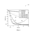
- FIG. 4 is a graphical representation 400 depicting exemplary convergence rates of certain image reconstruction methods with and without the use of momentum.
- the horizontal axis 402 corresponds to number of iterations and the vertical axis 404 corresponds to the root mean standard deviation (RMSD).
- the RMSD corresponds to the remaining error in image reconstruction. Thus, sharper the decrease in a curve, greater is the convergence rate of the corresponding image reconstruction method.
- FIG. 4 illustrates, for example, curves corresponding to a conventional OS-SQS-based method (see element 406 ), OS-SQS-based method employing the momentum terms determined using Version 1 or the Method 3 (hereinafter “MOM-1”, see element 408 ), and OS-SQS-based method employing the momentum terms determined using Version 3 or the Method 5 (hereinafter “MOM-3”, see element 410 ),
- FIG. 5 illustrates another graphical representation 500 depicting exemplary convergence rates of certain image reconstruction methods with and without the use of momentum.
- FIG. 5 illustrates curves representative of exemplary convergence rates of the various image reconstruction methods. Certain curves correspond to image reconstruction methods that employ a NU-OS-SQS-based method using MOM-3 with different number of subsets. As evident from the depictions of FIG. 5 , use of the NU approach provides substantial initial acceleration.
- FIG. 6 is a diagrammatical representation 600 depicting examples of initial images and corresponding converged images reconstructed using certain image reconstruction methods with or without the use of momentum.
- FIG. 6 illustrates an initial filtered back projection (FBP) image x (0) 602 and a corresponding converged image ⁇ circumflex over (x) ⁇ 604 for use as a reference.
- FIG. 6 further illustrates images reconstructed at 12th iteration from four different image reconstruction methods for comparison.
- use of the momentum term greatly accelerates convergence.
- the combination of NU and momentum with OS-based methods provides a converged image 606 having image quality substantially similar to the reference image 604 in only a few iterations.
- Embodiments of the present disclosure thus, provide methods and systems for accelerating iterative image reconstruction.
- the embodiments described herein allow for substantial reduction in computational costs involved in the iterative image reconstruction through use of OS and momentum.
- the present method uses a relatively small number of OS of the projection data per iteration and one or more momentum terms derived from previous iterations to allow expeditious updates to the image estimates, thereby improving the image reconstruction speed.
- Faster image reconstruction may circumvent a need for multiple scans and/or surgical intervention to assess a medical condition of a patient, thereby allowing for real-time diagnoses and providing substantial savings in computational effort and/or medical resources. Additionally, faster image reconstruction encourages wider use of iterative reconstruction methods, thereby enabling use of more low-dose CT scans.
- a processor-based system may include the control mechanism 208 , the DAS 214 , the computing device 216 , and/or the image reconstructor 230 of FIG. 2 .
- the steps may be performed using a special-purpose computer, multi-core CPU architecture, distributed cluster systems, general purpose graphical processor unit (GPU) architecture, and/or cloud-based systems.
- GPU general purpose graphical processor unit
- different implementations of the present disclosure may perform some or all of the steps described herein in different orders or substantially concurrently, that is, in parallel.
- the functions may be implemented in a variety of programming languages, including but not limited to Ruby, Hypertext Preprocessor (PHP), Perl, Delphi, Python, Matlab, Freemat, Octave, Interactive Data Language (IDL), FORTRAN, Cuda, openCL, C, C++, and/or Java.
- Such code may be stored or adapted for storage on one or more tangible, machine-readable media, such as on data repository chips, local or remote hard disks, optical disks (that is, CDs or DVDs), solid-state drives, or other media, which may be accessed by the processor-based system to execute the stored code.
Landscapes
- Engineering & Computer Science (AREA)
- Physics & Mathematics (AREA)
- Theoretical Computer Science (AREA)
- General Physics & Mathematics (AREA)
- Mathematical Analysis (AREA)
- Mathematical Optimization (AREA)
- Mathematical Physics (AREA)
- Pure & Applied Mathematics (AREA)
- Algebra (AREA)
- Apparatus For Radiation Diagnosis (AREA)
- Health & Medical Sciences (AREA)
- General Health & Medical Sciences (AREA)
- Medical Informatics (AREA)
- Nuclear Medicine, Radiotherapy & Molecular Imaging (AREA)
- Radiology & Medical Imaging (AREA)
- Quality & Reliability (AREA)
- Computer Vision & Pattern Recognition (AREA)
Abstract
Description
{circumflex over (x)}=argmin Ψ(x).
x≧0 (1)
Ψ(x)=½∥y−Ax∥ W 2 +βR(x) (2)
where A corresponds to a projection operator (a matrix that characterizes the imaging system), W corresponds to a diagonal matrix that provides statistical weighting, and R(x) corresponds to a regularization function that may be non-quadratic and differentiable. Further, β corresponds to a regularization parameter that balances between the data-fitting term ½∥y−Ax∥W 2 and the regularizer R(x).
∇Ψ(x)=A′W(Ax−y)+∇R(x) (3)
where A and A′ correspond to forward-projection and back-projection operators, respectively.
Minimize the surrogate: x (k+1)=argminx≧0φ(x;x (k)) (4)
Ψ(x (k))=φ(x (k) ;x (k))Ψ(x)≦φ(x;x (k)),∀xεR N
Ψ(x)≦φ(x;x (k))=Ψ(x (k))+∇Ψ(x (k))′(x−x (k))+½(x−x (k))′D(x−x (k)) (6)
where often D is designed such that equation (6) satisfies equation (5).
x (k+1) =x (k) −D −1∇Ψ(x (k)) (7)
where a majorizing matrix D may be derived, for example, using Lipschitz constant, De Pierro's lemma in NU-SQS algorithm, or other methods that yield a matrix that is easier to invert than the Hessian matrix of the original cost function.
for a diagonal majorizer D, or other invertible majorizing matrices.
v (k+1)=argminx≧0φ(x;x (k))
z (k+1)=argminx≧0ψ(x;x (k) ,v (k) ,z (k) , . . . ,x (0) ,v (0) ,z (0))
x (k+1)=(1−τk+1)v (k+1)+τk+1 Z (k+1) (9)
Version 2
x (k+1)=(1−τk)v (k)+τk z (k+1) (17)
which suggests that the convergence rate O(1/k2) may be achieved without using an optimization transfer inner step.
Version 3
and is a function of mth subset of measurement data, M is a number of subsets. Am, ym and Wm are submatrices of A, y and W, respectively that correspond to the mth subset of measured data.
∇Ψ(x)≈M∇Ψ 0(x)≈M∇Ψ 1(x)≈ . . . ≈M∇Ψ M−1(x) (23)
when each subset includes measurement data (for example, projection views) that are approximately uniformly down-sampled by M.
may be defined using equation (25) that represents an approximation of a surrogate
in equation (6).
Each mth sub-iteration in the OS-based Method 6 is counted as 1/M iteration as it uses approximately only 1/M of the amount of computation as compared to the computations involved in a corresponding iteration of the Method 1. However, the approximation defined in equation (23) may progressively become inaccurate as the iterates approach the minimizer or the solution image, and the OS-based methods lose the convergence property.
Version 2—(OS-MOM-2)
Version 3—(OS-MOM-3)
and
for the update of
in the momentum-based optimization transfer methods. In certain embodiments, the present method may be generalized to include other constraints, for example, box constraints, on the reconstruction. Furthermore, non-differentiable functions can be used as a cost function with a smoothing technique or other approaches that handle non-differentiable functions. Additionally, certain other OS-type algorithms such as incremental optimization transfer or relaxed variants of OS may be employed instead of ordinary OS algorithms for achieving faster convergence of the iterative image reconstruction via the use of momentum terms.
where Np,ROI is the number of voxels within ROI.
Claims (20)
Priority Applications (1)
| Application Number | Priority Date | Filing Date | Title |
|---|---|---|---|
| US14/045,816 US9489752B2 (en) | 2012-11-21 | 2013-10-04 | Ordered subsets with momentum for X-ray CT image reconstruction |
Applications Claiming Priority (2)
| Application Number | Priority Date | Filing Date | Title |
|---|---|---|---|
| US201261728909P | 2012-11-21 | 2012-11-21 | |
| US14/045,816 US9489752B2 (en) | 2012-11-21 | 2013-10-04 | Ordered subsets with momentum for X-ray CT image reconstruction |
Publications (2)
| Publication Number | Publication Date |
|---|---|
| US20140140599A1 US20140140599A1 (en) | 2014-05-22 |
| US9489752B2 true US9489752B2 (en) | 2016-11-08 |
Family
ID=50728005
Family Applications (1)
| Application Number | Title | Priority Date | Filing Date |
|---|---|---|---|
| US14/045,816 Active 2033-12-28 US9489752B2 (en) | 2012-11-21 | 2013-10-04 | Ordered subsets with momentum for X-ray CT image reconstruction |
Country Status (1)
| Country | Link |
|---|---|
| US (1) | US9489752B2 (en) |
Cited By (1)
| Publication number | Priority date | Publication date | Assignee | Title |
|---|---|---|---|---|
| US11915346B2 (en) | 2021-05-18 | 2024-02-27 | Elekta Limited | Iterative image reconstruction |
Families Citing this family (11)
| Publication number | Priority date | Publication date | Assignee | Title |
|---|---|---|---|---|
| WO2013111813A1 (en) * | 2012-01-27 | 2013-08-01 | 株式会社 東芝 | Medical image processing device |
| US9524567B1 (en) * | 2014-06-22 | 2016-12-20 | InstaRecon | Method and system for iterative computed tomography reconstruction |
| US9836858B2 (en) * | 2014-09-19 | 2017-12-05 | Siemens Aktiengesellschaft | Method for generating a combined projection image and imaging device |
| WO2017067997A1 (en) | 2015-10-20 | 2017-04-27 | Koninklijke Philips N.V. | Device and method for reconstructing an x-ray computed tomography image |
| CN106815453B (en) * | 2015-11-27 | 2019-05-14 | 华北电力大学 | Nuclear power plant's ray radiation source strength backstepping method and ray radiation source strength backstepping system |
| CN106991621B (en) * | 2016-01-20 | 2019-10-29 | 华北电力大学 | The recombination radiation source strength backstepping method and system of nuclear power plant's point source face source combination |
| CN106991620B (en) * | 2016-01-20 | 2019-10-29 | 华北电力大学 | The recombination radiation source strength backstepping method and system of nuclear power plant's line source face source combination |
| US10354417B2 (en) | 2016-09-13 | 2019-07-16 | Toshiba Medical Systems Corporation | Medical image processing apparatus and medical image diagnosis apparatus and medical image processing method |
| US9916670B1 (en) * | 2016-09-13 | 2018-03-13 | Toshiba Medical Systems Corporation | Fast, efficient, and list-mode compatible tomographic image reconstruction using a novel quadratic surrogate |
| US10692251B2 (en) * | 2017-01-13 | 2020-06-23 | Canon Medical Systems Corporation | Efficient variance-reduced method and apparatus for model-based iterative CT image reconstruction |
| US11087508B2 (en) | 2018-11-30 | 2021-08-10 | Canon Medical Systems Corporation | Method and apparatus for acceleration of iterative reconstruction of a computed tomography image |
Citations (20)
| Publication number | Priority date | Publication date | Assignee | Title |
|---|---|---|---|---|
| US6744845B2 (en) | 2001-04-03 | 2004-06-01 | Koninklijke Philips Electronics N.V. | Computed tomography apparatus for determining the pulse momentum transfer spectrum |
| US7042976B2 (en) | 2004-02-25 | 2006-05-09 | Canon Kabushiki Kaisha | Radiographic imaging apparatus |
| US20080095300A1 (en) * | 2006-10-05 | 2008-04-24 | General Electric Company | System and method for iterative reconstruction using parallel processing |
| US7386088B2 (en) * | 2004-09-24 | 2008-06-10 | General Electric Company | Method and system for iterative image reconstruction |
| US20090060124A1 (en) | 2004-11-11 | 2009-03-05 | Koninklijke Philips Electronics, N.V. | Energy resolved computer tomography |
| US20090112530A1 (en) * | 2007-10-31 | 2009-04-30 | Siemens Medical Solutions Usa, Inc. | Controlling the Number of Iterations in Image Reconstruction |
| US20090161933A1 (en) * | 2007-12-20 | 2009-06-25 | Guang-Hong Chen | Method for dynamic prior image constrained image reconstruction |
| US20090245458A1 (en) | 2006-05-16 | 2009-10-01 | Koninklijke Philips Electronics N.V. | Extension of the q-range in csct |
| US7623616B2 (en) | 2004-11-13 | 2009-11-24 | Kkoninklijke Philips Electronics N.V. | Computer tomography apparatus and method for examining an object of interest |
| US20100054394A1 (en) * | 2008-08-28 | 2010-03-04 | General Electric Company | Method and system for image reconstruction |
| US7711086B2 (en) | 2008-03-07 | 2010-05-04 | Morpho Detection, Inc. | Systems for improving a spatial resolution of an image |
| US7924978B2 (en) | 2008-02-22 | 2011-04-12 | Morpho Detection Inc. | System and method for XRD-based threat detection |
| US7937131B2 (en) | 2004-09-06 | 2011-05-03 | Gachon University Of Medicine & Science Industry-Academic Cooperation Foundation | PET—MRI hybrid apparatus and method of implementing the same |
| US20110164031A1 (en) * | 2010-01-06 | 2011-07-07 | Kabushiki Kaisha Toshiba | Novel implementation of total variation (tv) minimization iterative reconstruction algorithm suitable for parallel computation |
| US8063379B2 (en) | 2006-06-21 | 2011-11-22 | Avraham Suhami | Radiation cameras |
| US20120020448A1 (en) * | 2010-07-22 | 2012-01-26 | Kedar Bhalchandra Khare | System and method for reconstruction of x-ray images |
| US8116848B2 (en) | 1996-06-28 | 2012-02-14 | Ramin Shahidi | Method and apparatus for volumetric image navigation |
| US20120128265A1 (en) * | 2010-11-23 | 2012-05-24 | Toshiba Medical Systems Corporation | Method and system utilizing iterative reconstruction with adaptive parameters for computer tomography (ct) images |
| US20120155730A1 (en) * | 2010-09-21 | 2012-06-21 | Dimitris Metaxas | Image reconstruction |
| US20130320974A1 (en) * | 2012-06-01 | 2013-12-05 | Siemens Corporation | Efficient redundant haar minimization for parallel mri reconstruction |
-
2013
- 2013-10-04 US US14/045,816 patent/US9489752B2/en active Active
Patent Citations (20)
| Publication number | Priority date | Publication date | Assignee | Title |
|---|---|---|---|---|
| US8116848B2 (en) | 1996-06-28 | 2012-02-14 | Ramin Shahidi | Method and apparatus for volumetric image navigation |
| US6744845B2 (en) | 2001-04-03 | 2004-06-01 | Koninklijke Philips Electronics N.V. | Computed tomography apparatus for determining the pulse momentum transfer spectrum |
| US7042976B2 (en) | 2004-02-25 | 2006-05-09 | Canon Kabushiki Kaisha | Radiographic imaging apparatus |
| US7937131B2 (en) | 2004-09-06 | 2011-05-03 | Gachon University Of Medicine & Science Industry-Academic Cooperation Foundation | PET—MRI hybrid apparatus and method of implementing the same |
| US7386088B2 (en) * | 2004-09-24 | 2008-06-10 | General Electric Company | Method and system for iterative image reconstruction |
| US20090060124A1 (en) | 2004-11-11 | 2009-03-05 | Koninklijke Philips Electronics, N.V. | Energy resolved computer tomography |
| US7623616B2 (en) | 2004-11-13 | 2009-11-24 | Kkoninklijke Philips Electronics N.V. | Computer tomography apparatus and method for examining an object of interest |
| US20090245458A1 (en) | 2006-05-16 | 2009-10-01 | Koninklijke Philips Electronics N.V. | Extension of the q-range in csct |
| US8063379B2 (en) | 2006-06-21 | 2011-11-22 | Avraham Suhami | Radiation cameras |
| US20080095300A1 (en) * | 2006-10-05 | 2008-04-24 | General Electric Company | System and method for iterative reconstruction using parallel processing |
| US20090112530A1 (en) * | 2007-10-31 | 2009-04-30 | Siemens Medical Solutions Usa, Inc. | Controlling the Number of Iterations in Image Reconstruction |
| US20090161933A1 (en) * | 2007-12-20 | 2009-06-25 | Guang-Hong Chen | Method for dynamic prior image constrained image reconstruction |
| US7924978B2 (en) | 2008-02-22 | 2011-04-12 | Morpho Detection Inc. | System and method for XRD-based threat detection |
| US7711086B2 (en) | 2008-03-07 | 2010-05-04 | Morpho Detection, Inc. | Systems for improving a spatial resolution of an image |
| US20100054394A1 (en) * | 2008-08-28 | 2010-03-04 | General Electric Company | Method and system for image reconstruction |
| US20110164031A1 (en) * | 2010-01-06 | 2011-07-07 | Kabushiki Kaisha Toshiba | Novel implementation of total variation (tv) minimization iterative reconstruction algorithm suitable for parallel computation |
| US20120020448A1 (en) * | 2010-07-22 | 2012-01-26 | Kedar Bhalchandra Khare | System and method for reconstruction of x-ray images |
| US20120155730A1 (en) * | 2010-09-21 | 2012-06-21 | Dimitris Metaxas | Image reconstruction |
| US20120128265A1 (en) * | 2010-11-23 | 2012-05-24 | Toshiba Medical Systems Corporation | Method and system utilizing iterative reconstruction with adaptive parameters for computer tomography (ct) images |
| US20130320974A1 (en) * | 2012-06-01 | 2013-12-05 | Siemens Corporation | Efficient redundant haar minimization for parallel mri reconstruction |
Non-Patent Citations (3)
| Title |
|---|
| A Chambolle and T Pock, "A First-Order Primal-Dual Algorithm for Convex Problems with Applications to Imaging," J Math Imaging Vis (2011) 40:120-145. * |
| B De Man and JA Fessler, "Statistical Iterative Reconstruction for X-Ray Computed Tomography," Biomedical Mathematics: Promising Directions in Imaging, Therapy Planning and Inverse Problems, pp. 113-140. Medical Physics Publishing, Madison, WI, Jun. 30, 2010. ISBN: 9781930524484. * |
| S Ahn, JA Fessler, D Blatt, and AO Hero, "Convergent Incremental Optimization Transfer Algorithms: Application to Tomography," IEEE Trans. Med. Imag., vol. 25, No. 3, Mar. 2006. * |
Cited By (1)
| Publication number | Priority date | Publication date | Assignee | Title |
|---|---|---|---|---|
| US11915346B2 (en) | 2021-05-18 | 2024-02-27 | Elekta Limited | Iterative image reconstruction |
Also Published As
| Publication number | Publication date |
|---|---|
| US20140140599A1 (en) | 2014-05-22 |
Similar Documents
| Publication | Publication Date | Title |
|---|---|---|
| US9489752B2 (en) | Ordered subsets with momentum for X-ray CT image reconstruction | |
| CN110807737B (en) | Iterative image reconstruction framework | |
| US20220117570A1 (en) | Systems and methods for contrast flow modeling with deep learning | |
| JP6212294B2 (en) | Method and apparatus for iterative reconstruction | |
| JP6280700B2 (en) | Iterative reconstruction method, non-transitory computer readable medium and imaging system | |
| JP5860607B2 (en) | System and method for tomographic data collection and image reconstruction | |
| US9576391B2 (en) | Tomography apparatus and method of reconstructing a tomography image by the tomography apparatus | |
| JP2019069145A (en) | Medical image processing apparatus and medical image processing system | |
| JP6133089B2 (en) | System and method for attenuation compensation in nuclear medicine imaging based on emission data | |
| US9600924B2 (en) | Iterative reconstruction of image data in CT | |
| US9165385B2 (en) | Imaging procedure planning | |
| US8768030B2 (en) | CT measurement with multiple X-ray sources | |
| EP3107457B1 (en) | Tomography apparatus and method of reconstructing a tomography image by the tomography apparatus | |
| JP5913351B2 (en) | Forward projection device | |
| US10722178B2 (en) | Method and apparatus for motion correction in CT imaging | |
| JP2016152916A (en) | X-ray computer tomographic apparatus and medical image processing apparatus | |
| KR20100133950A (en) | Dose reduction and image enhancement in tomography through the utilization of the object's surroundings as dynamic constraints | |
| CN110751702A (en) | Image reconstruction method, system, device and storage medium | |
| US11141079B2 (en) | Systems and methods for profile-based scanning | |
| CN114067013A (en) | System and method for reprojection and backprojection via a homographic resampling transform | |
| US9984476B2 (en) | Methods and systems for automatic segmentation | |
| US20220375038A1 (en) | Systems and methods for computed tomography image denoising with a bias-reducing loss function | |
| JP7403585B2 (en) | Systems and methods for computed tomography image reconstruction | |
| US20160292874A1 (en) | Methods and systems for automatic segmentation | |
| US20190180481A1 (en) | Tomographic reconstruction with weights |
Legal Events
| Date | Code | Title | Description |
|---|---|---|---|
| AS | Assignment |
Owner name: GENERAL ELECTRIC COMPANY, NEW YORK Free format text: ASSIGNMENT OF ASSIGNORS INTEREST;ASSIGNORS:FU, LIN;DE MAN, BRUNO KRISTIAAN BERNARD;KIM, DONGHWAN;AND OTHERS;SIGNING DATES FROM 20130924 TO 20130930;REEL/FRAME:031573/0903 Owner name: THE REGENTS OF THE UNIVERSITY OF MICHIGAN, MICHIGA Free format text: ASSIGNMENT OF ASSIGNORS INTEREST;ASSIGNORS:FU, LIN;DE MAN, BRUNO KRISTIAAN BERNARD;KIM, DONGHWAN;AND OTHERS;SIGNING DATES FROM 20130924 TO 20130930;REEL/FRAME:031573/0903 |
|
| AS | Assignment |
Owner name: NATIONAL INSTITUTES OF HEALTH (NIH), U.S. DEPT. OF Free format text: CONFIRMATORY LICENSE;ASSIGNOR:UNIVERSITY OF MICHIGAN;REEL/FRAME:032689/0203 Effective date: 20131203 |
|
| STCF | Information on status: patent grant |
Free format text: PATENTED CASE |
|
| MAFP | Maintenance fee payment |
Free format text: PAYMENT OF MAINTENANCE FEE, 4TH YEAR, LARGE ENTITY (ORIGINAL EVENT CODE: M1551); ENTITY STATUS OF PATENT OWNER: LARGE ENTITY Year of fee payment: 4 |
|
| MAFP | Maintenance fee payment |
Free format text: PAYMENT OF MAINTENANCE FEE, 8TH YEAR, LARGE ENTITY (ORIGINAL EVENT CODE: M1552); ENTITY STATUS OF PATENT OWNER: LARGE ENTITY Year of fee payment: 8 |