US9473262B2 - Optical communication apparatus, optical communication system, and path control method - Google Patents

Optical communication apparatus, optical communication system, and path control method Download PDF

Info

Publication number
US9473262B2
US9473262B2 US13/610,476 US201213610476A US9473262B2 US 9473262 B2 US9473262 B2 US 9473262B2 US 201213610476 A US201213610476 A US 201213610476A US 9473262 B2 US9473262 B2 US 9473262B2
Authority
US
United States
Prior art keywords
optical communication
transponder
optical
recited
communication apparatus
Prior art date
Legal status (The legal status is an assumption and is not a legal conclusion. Google has not performed a legal analysis and makes no representation as to the accuracy of the status listed.)
Active, expires
Application number
US13/610,476
Other versions
US20130077969A1 (en
Inventor
Takeshi Nakata
Current Assignee (The listed assignees may be inaccurate. Google has not performed a legal analysis and makes no representation or warranty as to the accuracy of the list.)
NEC Corp
Original Assignee
NEC Corp
Priority date (The priority date is an assumption and is not a legal conclusion. Google has not performed a legal analysis and makes no representation as to the accuracy of the date listed.)
Filing date
Publication date
Application filed by NEC Corp filed Critical NEC Corp
Assigned to NEC CORPORATION reassignment NEC CORPORATION ASSIGNMENT OF ASSIGNORS INTEREST (SEE DOCUMENT FOR DETAILS). Assignors: NAKATA, TAKESHI
Publication of US20130077969A1 publication Critical patent/US20130077969A1/en
Application granted granted Critical
Publication of US9473262B2 publication Critical patent/US9473262B2/en
Active legal-status Critical Current
Adjusted expiration legal-status Critical

Links

Images

Classifications

    • HELECTRICITY
    • H04ELECTRIC COMMUNICATION TECHNIQUE
    • H04JMULTIPLEX COMMUNICATION
    • H04J14/00Optical multiplex systems
    • H04J14/02Wavelength-division multiplex systems
    • H04J14/0201Add-and-drop multiplexing
    • H04J14/0202Arrangements therefor
    • H04J14/021Reconfigurable arrangements, e.g. reconfigurable optical add/drop multiplexers [ROADM] or tunable optical add/drop multiplexers [TOADM]
    • H04J14/0212Reconfigurable arrangements, e.g. reconfigurable optical add/drop multiplexers [ROADM] or tunable optical add/drop multiplexers [TOADM] using optical switches or wavelength selective switches [WSS]
    • HELECTRICITY
    • H04ELECTRIC COMMUNICATION TECHNIQUE
    • H04JMULTIPLEX COMMUNICATION
    • H04J14/00Optical multiplex systems
    • H04J14/02Wavelength-division multiplex systems
    • H04J14/0201Add-and-drop multiplexing
    • H04J14/0215Architecture aspects
    • H04J14/0217Multi-degree architectures, e.g. having a connection degree greater than two
    • HELECTRICITY
    • H04ELECTRIC COMMUNICATION TECHNIQUE
    • H04JMULTIPLEX COMMUNICATION
    • H04J14/00Optical multiplex systems
    • H04J14/02Wavelength-division multiplex systems
    • H04J14/0201Add-and-drop multiplexing
    • H04J14/0202Arrangements therefor
    • H04J14/021Reconfigurable arrangements, e.g. reconfigurable optical add/drop multiplexers [ROADM] or tunable optical add/drop multiplexers [TOADM]

Definitions

  • the present invention relates to photonic network technology, and more particularly to an optical communication apparatus, an optical communication system, and a path control method for switching paths between nodes.
  • Patent Literature 1 Patent Literature 1, Patent Literature 2, and Non-Patent Literature 1 disclose some photonic network technology.
  • Patent Literature 1 discloses a drop circuit and an add circuit used in a reconfigurable optical add/drop multiplexer (ROADM device). Furthermore, Patent Literature 1 describes a colorless function using a wavelength selective switch (WSS). Patent Literature 1 also describes a direction function of switching paths to a different path with use of a wavelength cross connect device (WXC).
  • WSS wavelength selective switch
  • WXC wavelength cross connect device
  • Patent Literature 2 discloses a colorless function, a direction function, a wavelength cross connect device, a wavelength selective switch, and the like.
  • Non-Patent Literature 1 discloses such related technology.
  • a path of a channel ⁇ 1 currently connected is to be switched into a different path (ROADM 1 ⁇ >ROADM 4 ⁇ ROADM 3 ) using a channel ⁇ 2 (see FIG. 17 ).
  • channels change from a current one in some cases where, for example, signals using the same channel (wavelength) have already been transmitted on a new path. In such cases, a new path should be ensured by changing not only transmission paths, but also channels.
  • the amount of communication data flowing through optical networks may greatly vary in a day or several hours depending upon a variety of social activities (sports or musical events, incidents, accidents, and the like). As a countermeasure for such variations, therefore, operations of switching paths in an optical communication apparatus may be performed per day or a shorter period.
  • the present invention provides an optical communication apparatus, an optical communication system, and a path control method capable of improving at least one of the aforementioned problems.
  • an optical communication apparatus having a transponder having a double-wavelength tunable transceiver and a transceiver including a switching controller, and a ROADM device having a device that copes with a colorless function and a directionless function and can operate in cooperation with the transponder.
  • path switching can be conducted with short signal interruption or without instantaneous interruption by remote control.
  • FIG. 1 is a block diagram showing an example of a configuration of a network including a node device according to the present invention.
  • FIG. 2 is a block diagram showing an example of a configuration of a ROADM device and a transponder (TPND) included in a node device shown in FIG. 1 .
  • TPND transponder
  • FIG. 3 is a block diagram showing an example of a configuration of a network to which node devices according to the present invention are connected.
  • FIG. 4 is a block diagram showing another example of a configuration of a network to which node devices according to the present invention are connected.
  • FIG. 5 is a block diagram showing still another example of a configuration of a network to which node devices according to the present invention are connected.
  • FIG. 6 is a block diagram explanatory of a configuration of a transponder (TPND).
  • FIG. 7 is a block diagram explanatory of an initial state of a node.
  • FIG. 8 is a block diagram explanatory of operations between nodes in the state shown in FIG. 7 .
  • FIG. 9 is a block diagram explanatory of an operating state of a transponder (TPND).
  • FIG. 10 is a block diagram explanatory of another operating state of a node device according to the present invention.
  • FIG. 11 is a block diagram explanatory of operations between nodes in a transition state.
  • FIG. 12 is a block diagram explanatory of an operating state of a transponder (TPND) in a node device.
  • TPND transponder
  • FIG. 13 is a block diagram explanatory of operations between nodes in another state.
  • FIG. 14 is a diagram explanatory of an operation of an optical communication apparatus in a node device.
  • FIG. 15 is a block diagram explanatory of an operating state of a transponder (TPND) in a node device.
  • TPND transponder
  • FIG. 16 is a diagram explanatory of operations between nodes in related art.
  • FIG. 17 is a diagram explanatory of a switching operation in related art.
  • Embodiments of the present invention will be described in detail with reference to FIGS. 1 to 17 . Explanation of parts that do not directly relate to the present invention will be omitted or simplified.
  • FIG. 1 shows a configuration example of a network including node devices according to an embodiment of the present invention.
  • a node A and a node B are connected to each other via at least two paths by optical fibers.
  • a node device of each of the nodes includes a transponder (e.g., TPNDA- 1 or TPNDB- 1 ) and a reconfigurable optical add/drop multiplexer (e.g., ROADM_A or ROADM_B) according to the present invention.
  • the transponder includes a transceiver having a function of switching connections without instantaneous interruption by simultaneously using two channels (wavelengths).
  • the reconfigurable optical add/drop multiplexer has colorless and directionless functions or colorless, directionless, and contentionless functions.
  • the reconfigurable optical add/drop multiplexer can operate in cooperation with the transponder.
  • FIG. 1 illustrates a case where the number of connection paths of each of the nodes is four. Nodes are illustrated as being connected to each other by one line in FIG. 1 . However, one line in FIG. 1 represents two lines because two lines are usually used for two communication directions of an optical fiber. In a case where two-way communication is performed with a single line, only one line is used.
  • the transponders (TPND) and the reconfigurable optical add/drop multiplexers (ROADM) included in the nodes A and B form wavelength division multiplexing devices.
  • FIG. 1 A configuration of a ROADM device according to the present invention as shown in FIG. 1 will be described below with reference to FIG. 2 .
  • a ROADM device includes receiver modules R_ 1 to R_N and transmitter modules T_ 1 to T_N that can be connected to transmission lines, a wavelength cross connect (WXC) module that can exchange optical signals between the receiver modules and the transmitter modules, and an add part and a drop part that receive signals from and transmit signals to the WXC module and receive signals from and transmit signals to a local transponder (TPND).
  • the WXC module is formed by a wavelength selective switch (WSS) or the like.
  • the add-drop ratio should be 100%. Nevertheless, it will be difficult to ensure 100% from the viewpoints of cost and size if the number of channels or paths increases. Therefore, a low-cost design can readily be achieved by reducing the ratio to about 50%.
  • node devices are connected to each other by at least two paths.
  • node devices are also connected to each other by at least two paths.
  • FIG. 5 there is illustrated a network using ROADM devices in a case of a combination of a node A and a node B having different numbers of paths (Nd).
  • node devices are also connected to each other by at least two paths.
  • a ROADM device is applicable to various optical networks connected by at least two paths.
  • the transponder (TPND) connected to a ROADM device has a WDM transceiver part, an FEC signal processing part, a non-instantaneous-interruption switching part, and a client I/F transceiver part.
  • the transponder may be configured as shown in FIG. 9 or 12 .
  • the illustrated WDM transceiver part has transmitters (Tx 1 , Tx 2 ) with duplex channels based upon tunable laser technology.
  • the WDM transceiver part has digital coherent receivers (Rx 1 , Rx 2 ) with duplex channels. With this configuration, signals having two different wavelengths can be received concurrently, and electric signals can be outputted.
  • the FEC signal processing part is connected to the transmitters and the receivers of the WDM transceiver part. Since signals are duplexed, lines are also duplexed.
  • the FEC signal processing part operates as an error correction part.
  • the non-instantaneous-interruption switching part is disposed between the FEC signal processing part and the client I/F transceiver part.
  • the non-instantaneous-interruption switching part has a transmitting part for performing a signal multiplex (MUX), a receiving part for performing a signal demultiplex (DEMUX), and a part for performing signal comparison, delay adjustment, and SW operation.
  • MUX signal multiplex
  • DEMUX signal demultiplex
  • SW operation Data for phase detection are inputted to the part for performing signal comparison, delay adjustment, and SW operation.
  • the received data are stored in a memory so that the amount of delay can be adjusted.
  • the data for phase detection are detected by a delay measurement part, so that a phase shift is controlled.
  • a phase shift of a signal can be prevented.
  • channels can be switched by using an external signal as a trigger.
  • An output signal from the part for performing signal comparison, delay adjustment, and SW operation is inputted to one or more client interfaces via the client I/F transceiver part.
  • the illustrated transponder has a channel controller connected to a network path control part and a non-instantaneous-interruption switching controller.
  • the network path control part controls the channel controller in accordance with a predetermined program.
  • data inputted from clients are supplied to the transponder (TPND) shown in FIG. 6 , multiplexed therein, and then inputted to the transmitter Tx 1 of the WDM transceiver part.
  • the transmitter Tx 1 carries the data on a signal of a channel ⁇ 1 .
  • the data are inputted to the add part of ROADM 1 and outputted to the transmission line from T 1 .
  • the signal from ROADM 1 is transmitted to ROADM 2 and ROADM 3 in the network and thus transmitted to TPND 3 - 1 .
  • ROADM 3 receives the signal of ⁇ 1 from ROADM 1 at R 1 .
  • the WXC part outputs the signal to the drop part, which outputs the signal to the transponder (TPND).
  • the transponder part performs a delay adjustment on the signal received at RX 1 , then selects the signal with SW, and inputs the signal to the client I/F transceiver part, to which client transmitters are connected.
  • a signal in a reverse direction is inputted from a client signal terminal of the transponder (TPND) and outputted to a ROADM device through the client I/F transceiver part, the non-instantaneous-interruption switching part, the FEC part, TX 1 , and a 2 ⁇ 1 coupler as shown in FIG. 9 .
  • the ROADM device outputs the signal to the transmission line through the add part, WXC, and T 1 .
  • the 2 ⁇ 1 coupler is a couple with two inputs and one output.
  • ROADM 1 outputs the signal to the transponder (TPND) through R 1 , WXC, and the drop part.
  • the transponder (TPND) is connected to a client with a path extending through a 1 ⁇ 2 coupler, RX 1 , the FEC part, the non-instantaneous-interruption switching part, and the client transceiver part.
  • the 1 ⁇ 2 coupler is a couple with one input and two outputs.
  • a node can change paths or channels of optical signals without instantaneous interruption or only with considerably short interruption. Therefore, the node performs a double connection to the same receiver with a channel of ⁇ 2 , equalizes delays on the receiving side, conducts switching with an electric switch, and deletes the path of ⁇ 1 after successful switching.
  • a new path of ⁇ 2 is to be opened in the network.
  • the transponder (TPND) turns a transmission output of TX 2 shown in FIG. 12 on.
  • the signal at TX 2 is inputted to the add part through the same path in the ROADM device as that for ⁇ 1 , which has been described in connection with FIG. 10 .
  • the WXC part outputs the signal to T 2 .
  • this ROADM device copes with a colorless function, simultaneous connection to the add part can be established with different wavelengths. Furthermore, since this ROADM device copes with a directionless function, the add part can establish connection in any desired transmission direction (path).
  • the signal outputted to the transmission line from ROADM 3 is transmitted to ROADM 1 through ROADM 4 as shown in FIG. 11 .
  • ROADM 1 receives a signal from ROADM 4 at R 2 .
  • the WXC part connects the drop part.
  • the signal is inputted to the transponder (TPND) through the same path as that for ⁇ 1 .
  • a signal of ⁇ 1 and a signal of ⁇ 2 can be transmitted to the transponder (TPND) with the same path.
  • the transponder (TPND) outputs a signal of ⁇ 2 to the switch (SW) through the 1 ⁇ 2 coupler, RX 2 , and B 2 .
  • the switch still selects B 1 , so that signals from B 2 are discarded.
  • the delay control/switching part illustrated in FIG. 12 operates delays of B 1 and B 2 so as to equalize the delays of signals of two channels ( ⁇ 1 , ⁇ 2 ). After the delays are equalized, the paths are switched at a high speed by the switch. This operation allows the path to be switched into a path of ⁇ 2 without instantaneous interruption.
  • the non-instantaneous-interruption switching part adds a delay identification signal on the transmitting side.
  • the non-instantaneous-interruption switching part detects and removes the delay identification signal on the receiving side.
  • Switching without instantaneous interruption can be achieved by controlling delays between two channels based upon measured delays and equalizing those delays before the switching.
  • a difference of the delay is about 1 ms. Even if a difference of the path length of two signals is as long as about 1,000 km, a difference of the delay is about 5 ms.
  • a period of time of signal interruption is as short as about 5 ms.
  • Signal interruption occurs only when paths are switched from a path having shorter delay to a path having longer delay. Such short signal interruption enables very-high-speed path switching as compared to a path switching time of a ROADM device (0.1 second to 10 seconds).
  • the path switching time of a ROADM device depends upon a switching speed of devices including the add part, the transmission path, and the drop part.
  • a wavelength selective switch (WSS) on a path has a switching time on the order of 0.1 second to 10 seconds.
  • a period of time for transmitting a switching command to a WSS needs to be added. Therefore, when the entire network is considered, a path switching time requires a period on the order of 0.1 second to 10 seconds.
  • a signal of ⁇ 2 outputted from ROADM 1 is transmitted to ROADM 4 and ROADM 3 via the new path using ⁇ 2 in the network.
  • ROADM 3 receives the signal at R 2 (to which the new path has been connected), and the signal is transmitted to TPND via the WXC part and the drop part.
  • the transmitting side transmits the signal received from TPND to T 2 (a transmission part for the new path) via the add part and the WXC part. Then the signal is transmitted to the transmission line.
  • TPND transmits the signal to the client via the 1 ⁇ 2 coupler, R ⁇ 2 , B 2 , SW, and the client transceiver part.
  • the signal outputted from MUX is transmitted to the ROADM device via the 1 ⁇ 2 coupler, TX 2 , and the 2 ⁇ 1 coupler as shown in FIG. 15 .
  • disconnection time corresponding to a switching period of a ROADM device can be eliminated.
  • the speed of path switching can be increased up to a speed that is limited by an electric switching speed.
  • Path switching can be initiated at any desired timing if path switching can be conducted without instantaneous interruption.
  • paths and channels can be changed by a remote operation, it is possible to cooperate with a program that calculates the priority of paths and controls changing of paths based upon the priority of paths in order to optimize transmission paths.
  • a program that calculates the priority of paths and controls changing of paths based upon the priority of paths in order to optimize transmission paths.
  • a WDM transmission device has a CDC-ROADM and a transponder (TPND).
  • the ROADM device has a colorless function and a directionless function.
  • the transponder is configured to include a client I/F transceiver part, a non-instantaneous-interruption switching part, an FEC part, and a WDM transceiver part. Furthermore, the transponder has a controller operable to manage respective components in a centralized manner.
  • the client I/F transceiver part receives signals transmitted from a plurality of clients being connected, multiplexes them into one signal, and delivers the signal to WDM.
  • the client I/F transceiver part receives multiplexed signals from WDM and divides them into a plurality of client signals.
  • the non-instantaneous-interruption switching part is configured to compare inputted signals of multiple systems (two systems in the drawings) with each other, adjust one or both of delays of those signals, and switch the signals without instantaneous interruption.
  • the switching is conducted under the direction of a non-instantaneous-interruption controller.
  • the existing system may autonomously be switched into a posterior system while a delay that does not cause a loss of data is used as a key.
  • the FEC part (forward error correction part) is configured to have a function of performing an encoding process for WDM signals on multiplexed client signals and a function of decoding encoded signals received from WDM. Furthermore, the FEC part includes a correction comparison part operable to perform a decoding process on each of the systems upon signal decoding, to obtain the amount of correction for each of the systems, and to determine the quality of communication of each of the received systems from the obtained amount of correction. With this correction comparison part, the quality of transmission of the systems can be confirmed beforehand. As a result, appropriate system switching can be achieved.
  • the WDM transceiver part includes digital optical transmitter parts operable to transmit WDM signals generated in the FEC part to at least two fibers with desired channels (i.e., wavelengths) and digital optical receiver parts corresponding to the digital optical transmitters.
  • the digital receivers cope with multiple types of multi-level phase modulation methods such as DPSK, QPSK, and 8PSK.
  • the digital receivers are configured to change modulation methods for transmission in response to commands from a network path controller.
  • the transponder has a channel controller and a non-instantaneous-interruption switching controller mounted thereon as control parts.
  • the channel controller controls modulation methods or wavelengths of transmitting/receiving channels.
  • the non-instantaneous-interruption switching controller manages selection of a signal system to be transmitted to a client from among a plurality of systems of received WDM signals.
  • the control part is configured to control respective components of the transponder in response to commands from the network path controller, to constitute an optical network with a specified channel or the like, and to provide notification of the results.
  • An input and an output of the WDM transceiver part are respectively paired so that two connection terminals of the transponder are used. More input/output systems may be provided so as to provide an N+1 configuration.
  • Such a transponder is connected to a ROADM device having a colorless function, a directionless function, and a contentionless function in a network as shown in FIG. 1 .
  • the path 2 may be connected physically so that no manual operations of connecting fibers will be required later in a case where the node A and the node B are connected via the path 1 .
  • the paths can be switched.
  • the signal route connecting the transponders A- 1 and B- 1 to each other can be changed so as to level out rates of operation of the networks.
  • a digital optical transceiver for the path 2 is initiated, and setting for opening the path 2 is conducted on the network via a ROADM device.
  • Each of the transponders evaluates an error correction and a delay of the path 2 and determines whether or not switching can be conducted. If an error correction and a delay at a specified point of time are not more than predetermined values, the transponder determines that switching can be conducted, then equalizes the delays, and conducts path switching.
  • a jammed node can ensure a new path.
  • transponders (TPND) A- 1 and B- 1 By using the transponders (TPND) A- 1 and B- 1 according to the present invention, channels can be switched in a state in which the node A and the node B are connected to each other with the path 1 at the channel 1 .
  • a node in a halfway path has a request to open the channel 1 for another path and that the current channel is retracted to the channel ⁇ 2 .
  • second digital optical transceivers of the transponders are connected to each other with the channel ⁇ 2 .
  • Each of the transponders (TPND) evaluates an error correction and a delay of the path 2 and determines whether or not switching can be conducted. If an error correction and a delay at a specified point of time are not more than predetermined values, the transponder determines that switching can be conducted, then equalizes the delays, and conducts path switching.
  • signals can readily be switched during a switching operation of paths of signals.
  • an optical communication apparatus that can enhance a communication efficiency of data carried in an optical communication system.

Landscapes

  • Engineering & Computer Science (AREA)
  • Computer Networks & Wireless Communication (AREA)
  • Signal Processing (AREA)
  • Optical Communication System (AREA)

Abstract

An optical communication apparatus of a wavelength division multiplexing transmission system has a transponder having a double-wavelength tunable transceiver and a transceiver including a switching controller, and a ROADM device having a device that copes with a colorless function and a directionless function and can operate in cooperation with the transponder.

Description

This application is based upon and claims the benefit of priority from Japanese patent application No. 2011-208166, filed on Sep. 22, 2011, the disclosure of which is incorporated herein in its entirety by reference.
BACKGROUND
The present invention relates to photonic network technology, and more particularly to an optical communication apparatus, an optical communication system, and a path control method for switching paths between nodes.
In recent years, various technologies relating to a photonic network have been developed.
For example, Patent Literature 1, Patent Literature 2, and Non-Patent Literature 1 disclose some photonic network technology.
Patent Literature 1 discloses a drop circuit and an add circuit used in a reconfigurable optical add/drop multiplexer (ROADM device). Furthermore, Patent Literature 1 describes a colorless function using a wavelength selective switch (WSS). Patent Literature 1 also describes a direction function of switching paths to a different path with use of a wavelength cross connect device (WXC).
Similarly, Patent Literature 2 discloses a colorless function, a direction function, a wavelength cross connect device, a wavelength selective switch, and the like.
Furthermore, high-speed communication for 40 Gb/s or 100 Gb/s has been available in a digital optical transmission technology by using a phase modulating technique and a coherent receiving technique. For example, Non-Patent Literature 1 discloses such related technology.
For example, it is assumed that four nodes (Nd=4) are connected using ROADM devices having no colorless function or directionless function as shown in FIG. 16.
In this network, a path of a channel λ1 currently connected is to be switched into a different path (ROADM1→>ROADM4→ROADM3) using a channel λ2 (see FIG. 17).
In this case, there are required operations of preparing a new transponder TPND1-2 on ROADM1 of FIG. 17, opening a path of λ2, and finally changing a client. This is because the wavelength that can be transmitted to a connection port of a transponder is fixed if a ROADM device has no colorless function.
Even a ROADM device that copes with a colorless function needs to be connected to an add/drop part connected to a different path if it does not cope with a directionless function.
In order to switch optical transmission paths and channels (i.e., light wavelengths) of an optical communication apparatus that does not cope with a colorless function, an operator needs to go to an instillation site of a node and to directly rearrange an optical fiber into a connection terminal for a wavelength to be switched. This is because a remote operation cannot be performed since the channel of a ROADM device is fixed for a connection terminal of a transponder. At that time, an alternative transponder should be prepared in some cases. Such an operation arises problems requiring various costs such as cost of sending an operator, employment cost, facility cost, and cost of making a work planning. Furthermore, the downtime becomes longer along with a period of time required for such an operation. Thus, various problems will arise.
Even a ROADM device that copes with a colorless function suffers from signal interruption during a switching period of the ROADM device. In other words, primary signals cannot be transmitted during an operation of switching paths of a ROADM device (signal interruption period). Thus, transmission efficiency is problematically lowered.
When paths are to be switched, channels change from a current one in some cases where, for example, signals using the same channel (wavelength) have already been transmitted on a new path. In such cases, a new path should be ensured by changing not only transmission paths, but also channels.
In the field relating to the present invention, it has been desired to be capable of coping with various functions that will be provided in the near future. For example, the amount of communication data flowing through optical networks may greatly vary in a day or several hours depending upon a variety of social activities (sports or musical events, incidents, accidents, and the like). As a countermeasure for such variations, therefore, operations of switching paths in an optical communication apparatus may be performed per day or a shorter period.
  • Patent Literature 1: JP-A 2010-098545
  • Patent Literature 2: JP-A 2009-212584
  • Non-Patent Literature 1: Thesis “Performance of Dual-Polarization QPSK for Optical transport systems,” Kim Roberts, Maurice O'Sullivan, Kuang-Tsan Wu, Han Sun, Ahmed Awadalla, David J. Krause, and Charles Laperle, Journal of Lightwave technology, vol. 27. No. 6, 2009
SUMMARY OF THE INVENTION
The present invention provides an optical communication apparatus, an optical communication system, and a path control method capable of improving at least one of the aforementioned problems.
According to one aspect of the present invention, there is provided an optical communication apparatus having a transponder having a double-wavelength tunable transceiver and a transceiver including a switching controller, and a ROADM device having a device that copes with a colorless function and a directionless function and can operate in cooperation with the transponder.
Furthermore, when node devices including the aforementioned optical communication apparatus operate in cooperation with each other in a network having at least two different paths being connected, path switching can be conducted with short signal interruption or without instantaneous interruption by remote control.
BRIEF DESCRIPTION OF THE DRAWINGS
FIG. 1 is a block diagram showing an example of a configuration of a network including a node device according to the present invention.
FIG. 2 is a block diagram showing an example of a configuration of a ROADM device and a transponder (TPND) included in a node device shown in FIG. 1.
FIG. 3 is a block diagram showing an example of a configuration of a network to which node devices according to the present invention are connected.
FIG. 4 is a block diagram showing another example of a configuration of a network to which node devices according to the present invention are connected.
FIG. 5 is a block diagram showing still another example of a configuration of a network to which node devices according to the present invention are connected.
FIG. 6 is a block diagram explanatory of a configuration of a transponder (TPND).
FIG. 7 is a block diagram explanatory of an initial state of a node.
FIG. 8 is a block diagram explanatory of operations between nodes in the state shown in FIG. 7.
FIG. 9 is a block diagram explanatory of an operating state of a transponder (TPND).
FIG. 10 is a block diagram explanatory of another operating state of a node device according to the present invention.
FIG. 11 is a block diagram explanatory of operations between nodes in a transition state.
FIG. 12 is a block diagram explanatory of an operating state of a transponder (TPND) in a node device.
FIG. 13 is a block diagram explanatory of operations between nodes in another state.
FIG. 14 is a diagram explanatory of an operation of an optical communication apparatus in a node device.
FIG. 15 is a block diagram explanatory of an operating state of a transponder (TPND) in a node device.
FIG. 16 is a diagram explanatory of operations between nodes in related art.
FIG. 17 is a diagram explanatory of a switching operation in related art.
DETAILED DESCRIPTION OF THE PREFERRED EMBODIMENTS
Embodiments of the present invention will be described in detail with reference to FIGS. 1 to 17. Explanation of parts that do not directly relate to the present invention will be omitted or simplified.
FIG. 1 shows a configuration example of a network including node devices according to an embodiment of the present invention. In FIG. 1, a node A and a node B are connected to each other via at least two paths by optical fibers. A node device of each of the nodes includes a transponder (e.g., TPNDA-1 or TPNDB-1) and a reconfigurable optical add/drop multiplexer (e.g., ROADM_A or ROADM_B) according to the present invention. The transponder includes a transceiver having a function of switching connections without instantaneous interruption by simultaneously using two channels (wavelengths). The reconfigurable optical add/drop multiplexer has colorless and directionless functions or colorless, directionless, and contentionless functions. The reconfigurable optical add/drop multiplexer can operate in cooperation with the transponder. FIG. 1 illustrates a case where the number of connection paths of each of the nodes is four. Nodes are illustrated as being connected to each other by one line in FIG. 1. However, one line in FIG. 1 represents two lines because two lines are usually used for two communication directions of an optical fiber. In a case where two-way communication is performed with a single line, only one line is used. The transponders (TPND) and the reconfigurable optical add/drop multiplexers (ROADM) included in the nodes A and B form wavelength division multiplexing devices.
A configuration of a ROADM device according to the present invention as shown in FIG. 1 will be described below with reference to FIG. 2.
In a case where the number of paths is Nd (Nd is an integer larger than one), a ROADM device includes receiver modules R_1 to R_N and transmitter modules T_1 to T_N that can be connected to transmission lines, a wavelength cross connect (WXC) module that can exchange optical signals between the receiver modules and the transmitter modules, and an add part and a drop part that receive signals from and transmit signals to the WXC module and receive signals from and transmit signals to a local transponder (TPND). The WXC module is formed by a wavelength selective switch (WSS) or the like.
It is assumed that Ntp transponders can be connected to the illustrated add part and drop part. If the number of channels used in this system is Nch, the maximum of Ntp is Nd×Nch. A ratio of the number of connection ports (Ntp) actually prepared to the maximum of Ntp is referred to as a signal to add-drop ratio.
Add-drop ratio (%)=100×(the number of transponders prepared in a ROADM device (Ntp))/(Nd×Nch)
The add-drop ratio should be 100%. Nevertheless, it will be difficult to ensure 100% from the viewpoints of cost and size if the number of channels or paths increases. Therefore, a low-cost design can readily be achieved by reducing the ratio to about 50%.
A network may be configured using the illustrated ROADM devices as shown in FIG. 3, which illustrates a connection example where Nd=2. In this case, node devices are connected to each other by at least two paths.
Referring to FIG. 4, there is illustrated a network using ROADM devices in a case where Nd=4. In this case, node devices are also connected to each other by at least two paths.
Referring to FIG. 5, there is illustrated a network using ROADM devices in a case of a combination of a node A and a node B having different numbers of paths (Nd). In this case, node devices are also connected to each other by at least two paths.
As shown in FIGS. 3 to 5, a ROADM device according to the present invention is applicable to various optical networks connected by at least two paths.
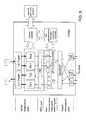
An example of a configuration of a transponder (TPND) according to an embodiment of the present invention will be described with reference to FIG. 6. As shown in FIG. 6, the transponder (TPND) connected to a ROADM device has a WDM transceiver part, an FEC signal processing part, a non-instantaneous-interruption switching part, and a client I/F transceiver part. The transponder may be configured as shown in FIG. 9 or 12.
The illustrated WDM transceiver part has transmitters (Tx1, Tx2) with duplex channels based upon tunable laser technology.
The WDM transceiver part has digital coherent receivers (Rx1, Rx2) with duplex channels. With this configuration, signals having two different wavelengths can be received concurrently, and electric signals can be outputted.
The FEC signal processing part is connected to the transmitters and the receivers of the WDM transceiver part. Since signals are duplexed, lines are also duplexed. The FEC signal processing part operates as an error correction part.
The non-instantaneous-interruption switching part is disposed between the FEC signal processing part and the client I/F transceiver part. The non-instantaneous-interruption switching part has a transmitting part for performing a signal multiplex (MUX), a receiving part for performing a signal demultiplex (DEMUX), and a part for performing signal comparison, delay adjustment, and SW operation. Data for phase detection are inputted to the part for performing signal comparison, delay adjustment, and SW operation. The received data are stored in a memory so that the amount of delay can be adjusted.
Then the data for phase detection are detected by a delay measurement part, so that a phase shift is controlled. Thus, a phase shift of a signal can be prevented. Furthermore, channels can be switched by using an external signal as a trigger.
An output signal from the part for performing signal comparison, delay adjustment, and SW operation is inputted to one or more client interfaces via the client I/F transceiver part.
Furthermore, the illustrated transponder (TPND) has a channel controller connected to a network path control part and a non-instantaneous-interruption switching controller. The network path control part controls the channel controller in accordance with a predetermined program.
Operations of the network illustrated in FIG. 1 will be described below with reference to FIGS. 7 to 9.
(Initial State: Connection with λ1)
As shown in FIG. 7, data inputted from clients are supplied to the transponder (TPND) shown in FIG. 6, multiplexed therein, and then inputted to the transmitter Tx1 of the WDM transceiver part. The transmitter Tx1 carries the data on a signal of a channel λ1. The data are inputted to the add part of ROADM1 and outputted to the transmission line from T1.
Referring to FIG. 8, the signal from ROADM1 is transmitted to ROADM2 and ROADM3 in the network and thus transmitted to TPND3-1.
As shown in FIG. 7, ROADM3 receives the signal of λ1 from ROADM1 at R1. The WXC part outputs the signal to the drop part, which outputs the signal to the transponder (TPND).
As shown in FIG. 6, the transponder part (TPND) performs a delay adjustment on the signal received at RX1, then selects the signal with SW, and inputs the signal to the client I/F transceiver part, to which client transmitters are connected.
Similarly, a signal in a reverse direction is inputted from a client signal terminal of the transponder (TPND) and outputted to a ROADM device through the client I/F transceiver part, the non-instantaneous-interruption switching part, the FEC part, TX1, and a 2×1 coupler as shown in FIG. 9. As shown in FIG. 10, the ROADM device outputs the signal to the transmission line through the add part, WXC, and T1. In FIG. 9, the 2×1 coupler is a couple with two inputs and one output.
Furthermore, as shown in FIG. 8, the aforementioned signal in the reverse direction is outputted from ROAMD3 to ROADM1 through the transmission line, ROADM2, and the transmission line. As shown in FIG. 10, ROADM1 outputs the signal to the transponder (TPND) through R1, WXC, and the drop part.
As shown in FIG. 9, the transponder (TPND) is connected to a client with a path extending through a 1×2 coupler, RX1, the FEC part, the non-instantaneous-interruption switching part, and the client transceiver part. In FIG. 9, the 1×2 coupler is a couple with one input and two outputs.
(Transition State)
A node according to an embodiment of the present invention can change paths or channels of optical signals without instantaneous interruption or only with considerably short interruption. Therefore, the node performs a double connection to the same receiver with a channel of λ2, equalizes delays on the receiving side, conducts switching with an electric switch, and deletes the path of λ1 after successful switching.
(1) Connection with λ2
As shown in FIG. 11, a new path of λ2 is to be opened in the network. The transponder (TPND) turns a transmission output of TX2 shown in FIG. 12 on. Then the signal at TX2 is inputted to the add part through the same path in the ROADM device as that for λ1, which has been described in connection with FIG. 10. Then the WXC part outputs the signal to T2.
Since this ROADM device copes with a colorless function, simultaneous connection to the add part can be established with different wavelengths. Furthermore, since this ROADM device copes with a directionless function, the add part can establish connection in any desired transmission direction (path).
The signal outputted to the transmission line from ROADM3 is transmitted to ROADM1 through ROADM4 as shown in FIG. 11.
As shown in FIG. 10, ROADM1 receives a signal from ROADM4 at R2. The WXC part connects the drop part. Then the signal is inputted to the transponder (TPND) through the same path as that for λ1.
Since a ROADM device according to the present invention copes with a colorless function, a signal of λ1 and a signal of λ2 can be transmitted to the transponder (TPND) with the same path.
As shown in FIG. 12, the transponder (TPND) outputs a signal of λ2 to the switch (SW) through the 1×2 coupler, RX2, and B2. At that time, the switch still selects B1, so that signals from B2 are discarded.
(2) Switching without Instantaneous Interruption or with Short Interruption
When a signal of λ2 is connected, the delay control/switching part illustrated in FIG. 12 operates delays of B1 and B2 so as to equalize the delays of signals of two channels (λ1, λ2). After the delays are equalized, the paths are switched at a high speed by the switch. This operation allows the path to be switched into a path of λ2 without instantaneous interruption.
The non-instantaneous-interruption switching part adds a delay identification signal on the transmitting side. The non-instantaneous-interruption switching part detects and removes the delay identification signal on the receiving side.
Switching without instantaneous interruption can be achieved by controlling delays between two channels based upon measured delays and equalizing those delays before the switching.
Even if the delays cannot be equalized, the loss of signals can be minimized by adjusting the delays as much as possible.
Even if a difference of the path length of two signals is as long as about 200 km, a difference of the delay is about 1 ms. Even if a difference of the path length of two signals is as long as about 1,000 km, a difference of the delay is about 5 ms.
Thus, even if delays cannot be equalized, a period of time of signal interruption is as short as about 5 ms.
Signal interruption occurs only when paths are switched from a path having shorter delay to a path having longer delay. Such short signal interruption enables very-high-speed path switching as compared to a path switching time of a ROADM device (0.1 second to 10 seconds).
The path switching time of a ROADM device depends upon a switching speed of devices including the add part, the transmission path, and the drop part.
In most cases, a wavelength selective switch (WSS) on a path has a switching time on the order of 0.1 second to 10 seconds.
Furthermore, a period of time for transmitting a switching command to a WSS needs to be added. Therefore, when the entire network is considered, a path switching time requires a period on the order of 0.1 second to 10 seconds.
(Termination State)
Only the new path of λ2 is occupied for communication.
As shown in FIG. 13, a signal of λ2 outputted from ROADM1 is transmitted to ROADM4 and ROADM3 via the new path using λ2 in the network.
As shown in FIG. 14, ROADM3 receives the signal at R2 (to which the new path has been connected), and the signal is transmitted to TPND via the WXC part and the drop part.
The transmitting side transmits the signal received from TPND to T2 (a transmission part for the new path) via the add part and the WXC part. Then the signal is transmitted to the transmission line.
As shown in FIG. 15, TPND transmits the signal to the client via the 1×2 coupler, Rλ2, B2, SW, and the client transceiver part.
In the transmitting part of TPND, the signal outputted from MUX is transmitted to the ROADM device via the 1×2 coupler, TX2, and the 2×1 coupler as shown in FIG. 15.
The following advantageous effects can be obtained by using a WDM transmission device according to the present invention.
For path switching of switching transmission paths and transmission channels, disconnection time corresponding to a switching period of a ROADM device can be eliminated. Thus, the speed of path switching can be increased up to a speed that is limited by an electric switching speed.
Delays between paths can be corrected. Path switching can be initiated at any desired timing if path switching can be conducted without instantaneous interruption.
For path switching including changing transmission paths and channels, it is not necessary to manually rearrange a fiber. Employment cost and work planning cost required for fiber rearrangement can be reduced, and a period of time for such an operation can be shortened.
Since paths and channels can be changed by a remote operation, it is possible to cooperate with a program that calculates the priority of paths and controls changing of paths based upon the priority of paths in order to optimize transmission paths. Thus, when one path is deleted or changed, the existing other communication paths can automatically be reconnected with optimal paths.
Some features of the present invention will be added below.
A WDM transmission device according to an embodiment of the present invention has a CDC-ROADM and a transponder (TPND).
The ROADM device has a colorless function and a directionless function.
Meanwhile, the transponder is configured to include a client I/F transceiver part, a non-instantaneous-interruption switching part, an FEC part, and a WDM transceiver part. Furthermore, the transponder has a controller operable to manage respective components in a centralized manner.
The client I/F transceiver part receives signals transmitted from a plurality of clients being connected, multiplexes them into one signal, and delivers the signal to WDM. The client I/F transceiver part receives multiplexed signals from WDM and divides them into a plurality of client signals.
The non-instantaneous-interruption switching part is configured to compare inputted signals of multiple systems (two systems in the drawings) with each other, adjust one or both of delays of those signals, and switch the signals without instantaneous interruption.
The switching is conducted under the direction of a non-instantaneous-interruption controller. Upon inputting and switching of the same signals, the existing system may autonomously be switched into a posterior system while a delay that does not cause a loss of data is used as a key.
The FEC part (forward error correction part) is configured to have a function of performing an encoding process for WDM signals on multiplexed client signals and a function of decoding encoded signals received from WDM. Furthermore, the FEC part includes a correction comparison part operable to perform a decoding process on each of the systems upon signal decoding, to obtain the amount of correction for each of the systems, and to determine the quality of communication of each of the received systems from the obtained amount of correction. With this correction comparison part, the quality of transmission of the systems can be confirmed beforehand. As a result, appropriate system switching can be achieved.
The WDM transceiver part includes digital optical transmitter parts operable to transmit WDM signals generated in the FEC part to at least two fibers with desired channels (i.e., wavelengths) and digital optical receiver parts corresponding to the digital optical transmitters.
Furthermore, the digital receivers cope with multiple types of multi-level phase modulation methods such as DPSK, QPSK, and 8PSK. The digital receivers are configured to change modulation methods for transmission in response to commands from a network path controller.
The transponder has a channel controller and a non-instantaneous-interruption switching controller mounted thereon as control parts. The channel controller controls modulation methods or wavelengths of transmitting/receiving channels. The non-instantaneous-interruption switching controller manages selection of a signal system to be transmitted to a client from among a plurality of systems of received WDM signals.
The control part is configured to control respective components of the transponder in response to commands from the network path controller, to constitute an optical network with a specified channel or the like, and to provide notification of the results.
An input and an output of the WDM transceiver part are respectively paired so that two connection terminals of the transponder are used. More input/output systems may be provided so as to provide an N+1 configuration.
Such a transponder is connected to a ROADM device having a colorless function, a directionless function, and a contentionless function in a network as shown in FIG. 1.
By using the transponders (TPND) (e.g., A-1 and B-1) according to the present invention, the path 2 may be connected physically so that no manual operations of connecting fibers will be required later in a case where the node A and the node B are connected via the path 1. Thus, the paths can be switched.
When the node connecting via the path 1 is jammed by other signal connections, path changes, and the like, then the signal route connecting the transponders A-1 and B-1 to each other can be changed so as to level out rates of operation of the networks.
First, a digital optical transceiver for the path 2 is initiated, and setting for opening the path 2 is conducted on the network via a ROADM device.
Each of the transponders (TPND) evaluates an error correction and a delay of the path 2 and determines whether or not switching can be conducted. If an error correction and a delay at a specified point of time are not more than predetermined values, the transponder determines that switching can be conducted, then equalizes the delays, and conducts path switching.
When the switching succeeds, the path 1 is opened.
Thus, a jammed node can ensure a new path.
By using the transponders (TPND) A-1 and B-1 according to the present invention, channels can be switched in a state in which the node A and the node B are connected to each other with the path 1 at the channel 1.
Specifically, it is assumed that a node in a halfway path has a request to open the channel 1 for another path and that the current channel is retracted to the channel λ2.
First, second digital optical transceivers of the transponders (TPND) are connected to each other with the channel λ2. Each of the transponders (TPND) evaluates an error correction and a delay of the path 2 and determines whether or not switching can be conducted. If an error correction and a delay at a specified point of time are not more than predetermined values, the transponder determines that switching can be conducted, then equalizes the delays, and conducts path switching.
When the switching succeeds, the channel 1 of the path 1 is opened.
Thus, optimization of channel configuration on the same path can be achieved without instantaneous interruption.
As described above, according to the present invention, signals can readily be switched during a switching operation of paths of signals. Thus, there can be provided an optical communication apparatus that can enhance a communication efficiency of data carried in an optical communication system.
Furthermore, a specific configuration of the present invention is not limited to the aforementioned embodiment. It should be understood that various changes and modifications may be made therein without departing from the spirit of the present invention.

Claims (16)

What is claimed is:
1. An optical communication apparatus, comprising:
a transponder comprising a plurality of transceivers operable in response to optical signals of different wavelengths through which data are received/transmitted, a switching part which switches the plurality of transceivers from one to another, and a switching controller controlling the switching part; and
a reconfigurable optical add/drop multiplexer including a device that copes with a colorless function and a directionless function and is configured to operate in cooperation with the transponder,
wherein each receiver of the plurality of the transceivers includes a receiver part which receives the optical signals of the different wavelengths and which outputs electric signals, and
wherein the switching part is structured by a non-instantaneous-interruption switching part which includes a part for signal delay adjustment of the data received/transmitted through the different wavelengths.
2. The optical communication apparatus as recited in claim 1, wherein said each receiver of the plurality of the transceivers is structured by a wavelength division multiplexing (WDM) transceiver, a transmitter, and a receiver,
wherein the transponder further comprises:
a coupler which includes multiple inputs and a single output and which is connected to outputs of the plurality of transmitters, and
a coupler which includes a single input and multiple outputs and which is connected to inputs of the plurality of receivers.
3. The optical communication apparatus as recited in claim 1, wherein the transponder includes an error correction part operable to perform an error correction.
4. The optical communication apparatus as recited in claim 1, wherein the transponder includes a channel controller operable to manage a channel of an optical signal transmitted to or received from the reconfigurable optical add/drop multiplexer based upon a control signal for determining a network path.
5. The optical communication apparatus as recited in claim 1, wherein the reconfigurable optical add/drop multiplexer includes a transceiver module connectable to a predetermined number of transmission lines, a wavelength cross connector module operable to switch optical signals, and an add part and a drop part connected to the transponder.
6. The optical communication apparatus as recited in claim 5, wherein the add part and the drop part are configured to be capable of coping with a plurality of paths.
7. An optical communication system, comprising:
a plurality of nodes each including the optical communication apparatus as recited in claim 1.
8. The optical communication system as recited in claim 7, wherein a path of λ1 that is connected to the plurality of nodes is configured to automatically be switched into another path of λ2 that is different from λ1.
9. An optical communication system including a plurality of nodes each including an optical communication apparatus as recited in claim 1, wherein the transponder includes a wavelength division multiplexing (WDM) transceiver part including a plurality of transmitters and a plurality of receivers,
wherein a coupler with multiple inputs and a single output is connected to outputs of the plurality of transmitters, and
wherein a coupler with a single input and multiple outputs is connected to inputs of the plurality of receivers.
10. An optical communication system including a plurality of nodes each including an optical communication apparatus as recited in claim 1, wherein the transponder includes a non-instantaneous-interruption switching controller operable to control the non-instantaneous-interruption switching part.
11. An optical communication system including a plurality of nodes each including an optical communication apparatus as recited in claim 1, wherein the transponder includes a non-instantaneous-interruption switching controller operable to control the non-instantaneous-interruption switching part, and
wherein the transponder further includes an error correction part operable to perform an error correction.
12. An optical communication system including a plurality of nodes each including an optical communication apparatus as recited in claim 1, wherein the transponder includes a channel controller operable to manage a channel of an optical signal transmitted to or received from the reconfigurable optical add/drop multiplexer based upon a control signal for determining a network path.
13. An optical communication system including a plurality of nodes each including an optical communication apparatus as recited in claim 1, wherein the reconfigurable optical add/drop multiplexer includes a transceiver module connectable to a predetermined number of transmission lines, a wavelength cross connector module operable to switch optical signals, and an add part and a drop part connected to the transponder.
14. An optical communication system including a plurality of nodes each including an optical communication apparatus as recited in claim 1, wherein the reconfigurable optical add/drop multiplexer includes a transceiver module connectable to a predetermined number of transmission lines, a wavelength cross connector module operable to switch optical signals, and an add part and a drop part connected to the transponder, and
wherein the add part and the drop part are configured to be capable of coping with a plurality of paths.
15. A transponder, comprising:
a plurality of transceivers operable in response to optical signals of different wavelengths through which data are received/transmitted;
a switching part which switches the plurality of transceivers from one to another; and
a client I/F transceiver part placed between the switching part and a plurality of clients,
wherein the client I/F transceiver part comprises a multiplexer/demultiplexer connected to the switching part and the plurality of the clients,
wherein the switching part is structured by a non-instantaneous interruption switch operable when the plurality of the transceivers are switched from one to another, and
wherein the non-instantaneous interruption switch is operable to adjust and/or delay the data received/transmitted through the different wavelengths.
16. A transponder as recited in claim 15, further comprising a switching controller connected to the non-instantaneous interruption switch to equalize delays of the data.
US13/610,476 2011-09-22 2012-09-11 Optical communication apparatus, optical communication system, and path control method Active 2034-04-16 US9473262B2 (en)

Applications Claiming Priority (2)

Application Number Priority Date Filing Date Title
JP2011208166A JP5904320B2 (en) 2011-09-22 2011-09-22 Optical communication apparatus, optical communication system, and path control method
JP2011-208166 2011-09-22

Publications (2)

Publication Number Publication Date
US20130077969A1 US20130077969A1 (en) 2013-03-28
US9473262B2 true US9473262B2 (en) 2016-10-18

Family

ID=47911417

Family Applications (1)

Application Number Title Priority Date Filing Date
US13/610,476 Active 2034-04-16 US9473262B2 (en) 2011-09-22 2012-09-11 Optical communication apparatus, optical communication system, and path control method

Country Status (2)

Country Link
US (1) US9473262B2 (en)
JP (1) JP5904320B2 (en)

Families Citing this family (2)

* Cited by examiner, † Cited by third party
Publication number Priority date Publication date Assignee Title
CN102907022B (en) * 2010-06-03 2016-08-03 瑞典爱立信有限公司 Optical network node with restoration path
JP6320953B2 (en) * 2015-03-04 2018-05-09 日本電信電話株式会社 Optical transmission system and optical transmission method

Citations (27)

* Cited by examiner, † Cited by third party
Publication number Priority date Publication date Assignee Title
US6072610A (en) * 1996-04-15 2000-06-06 Fujitsu Limited Optical transmission system
US6130764A (en) * 1997-10-20 2000-10-10 Fujitsu Limited Transmission apparatus in ring network
US20020097460A1 (en) 2001-01-25 2002-07-25 Yoshiaki Ikoma Optical network system with quality control function
JP2006041921A (en) 2004-07-27 2006-02-09 Mitsubishi Electric Corp Uninterruptible switching device
US20080050117A1 (en) * 2006-06-12 2008-02-28 Bikash Koley Method and apparatus for photonic resiliency of a packet switched network
US20080131130A1 (en) * 2006-12-05 2008-06-05 Electronics And Telecommunications Research Institute Optical network node device
US20090116839A1 (en) * 2007-08-24 2009-05-07 Hitachi Communications Technologies, Ltd. Optical transmission system and signal speed converting apparatus
WO2009060522A1 (en) 2007-11-07 2009-05-14 Fujitsu Limited Optical transceiver module, management control method thereof, optical transceiver device, and wavelength multiplexing optical transceiver device
US20090220242A1 (en) 2008-02-29 2009-09-03 Fujitsu Limited Optical adding and dropping device and optical transmission apparatus
US20090238089A1 (en) * 2008-03-18 2009-09-24 Kitajima Katsuya Ethernet transmission method, transmission apparatus and system
WO2009145118A1 (en) 2008-05-26 2009-12-03 日本電気株式会社 Wavelength path communication node device, wavelength path communication control method, program, and recording medium
JP2010098545A (en) 2008-10-16 2010-04-30 Nippon Telegr & Teleph Corp <Ntt> Optical transmission apparatus
US20100232782A1 (en) * 2009-03-10 2010-09-16 Fujitsu Limited Optical transmission device, optical transmission system including the same, and optical transmission method
US20100322354A1 (en) * 2008-02-18 2010-12-23 Shinji Tanimoto Transmitting method, receiving method, transmitting device, receiving device, transmission apparatus and transmission system
WO2011030897A1 (en) 2009-09-14 2011-03-17 日本電信電話株式会社 Band-variable communication method, band-variable communication apparatus, transmission band deciding apparatus, transmission band deciding method, node apparatus, communication path setting system, and communication path setting method
JP2011101216A (en) 2009-11-06 2011-05-19 Fujitsu Ltd Optical transmitter and method for controlling wavelength variable optical output unit
US7953106B2 (en) * 2008-03-11 2011-05-31 Hitachi, Ltd. Transmission apparatus
US8009986B2 (en) * 2006-11-17 2011-08-30 Electronics And Telecommunications Research Institute Optical node for mesh-type WDM optical network
US20110262142A1 (en) * 2010-04-27 2011-10-27 Jean-Luc Archambault Reconfigurable optical add drop multiplexer node automated topology discovery systems and methods
US20110274425A1 (en) * 2010-05-07 2011-11-10 Klaus Grobe Method for providing protection in an optical communication network against connection failures
US20110293279A1 (en) * 2010-05-26 2011-12-01 Google Inc. Tunable Multi-Wavelength Optical Transmitter and Transceiver for Optical Communications Based on Wavelength Division Multiplexing
US20110317998A1 (en) * 2009-03-10 2011-12-29 Atsushi Fujimura Delay amount allocation means, delay amount allocation method and a computer readable recording medium which records control program of delay amount allocation means
US8346089B2 (en) * 2009-09-29 2013-01-01 At&T Intellectual Property I, L.P. Methods for expanding cross-connect capacity in a ROADM optical network
US9209901B2 (en) * 2012-11-20 2015-12-08 Telefonaktiebolaget L M Ericsson (Publ) Configurable single-fiber or dual-fiber optical transceiver
US9240856B2 (en) * 2011-07-29 2016-01-19 Nec Corporation Network system, network apparatus, and method of controlling network
US9301027B2 (en) * 2012-06-06 2016-03-29 Techsys Insights Remote optical demarcation point protection
US20160099851A1 (en) * 2014-10-01 2016-04-07 Ciena Corporation Method and system for optical connection validation in a reconfigurable optical add-drop multiplexer (roadm) node

Family Cites Families (3)

* Cited by examiner, † Cited by third party
Publication number Priority date Publication date Assignee Title
JP5085365B2 (en) * 2008-02-13 2012-11-28 日本電信電話株式会社 Node device and extra-traffic transmission / reception method
JP5206211B2 (en) * 2008-08-07 2013-06-12 日本電気株式会社 WDM network and node equipment
JP2011130078A (en) * 2009-12-16 2011-06-30 Mitsubishi Electric Corp Wavelength multiplex transmission apparatus

Patent Citations (36)

* Cited by examiner, † Cited by third party
Publication number Priority date Publication date Assignee Title
US6072610A (en) * 1996-04-15 2000-06-06 Fujitsu Limited Optical transmission system
US6130764A (en) * 1997-10-20 2000-10-10 Fujitsu Limited Transmission apparatus in ring network
US20020097460A1 (en) 2001-01-25 2002-07-25 Yoshiaki Ikoma Optical network system with quality control function
JP2002223197A (en) 2001-01-25 2002-08-09 Hitachi Ltd Optical network system having quality control function
US6990294B2 (en) 2001-01-25 2006-01-24 Hitachi, Ltd Optical network system with quality control function
JP2006041921A (en) 2004-07-27 2006-02-09 Mitsubishi Electric Corp Uninterruptible switching device
US20080050117A1 (en) * 2006-06-12 2008-02-28 Bikash Koley Method and apparatus for photonic resiliency of a packet switched network
US8009986B2 (en) * 2006-11-17 2011-08-30 Electronics And Telecommunications Research Institute Optical node for mesh-type WDM optical network
US20080131130A1 (en) * 2006-12-05 2008-06-05 Electronics And Telecommunications Research Institute Optical network node device
US20090116839A1 (en) * 2007-08-24 2009-05-07 Hitachi Communications Technologies, Ltd. Optical transmission system and signal speed converting apparatus
US20100209113A1 (en) 2007-11-07 2010-08-19 Fujitsu Limited Light transmitting and receiving module, and method for managing the same, light transmitting and receiving apparatus, and wavelength-multiplexing light transmitting and receiving apparatus
WO2009060522A1 (en) 2007-11-07 2009-05-14 Fujitsu Limited Optical transceiver module, management control method thereof, optical transceiver device, and wavelength multiplexing optical transceiver device
US8396362B2 (en) 2007-11-07 2013-03-12 Fujitsu Limited Light transmitting and receiving module, method for managing the same, light transmitting and receiving apparatus, and wavelength-multiplexing light transmitting and receiving apparatus
US20100322354A1 (en) * 2008-02-18 2010-12-23 Shinji Tanimoto Transmitting method, receiving method, transmitting device, receiving device, transmission apparatus and transmission system
JP2009212584A (en) 2008-02-29 2009-09-17 Fujitsu Ltd Optical adding and dropping device and optical transmission apparatus
US20090220242A1 (en) 2008-02-29 2009-09-03 Fujitsu Limited Optical adding and dropping device and optical transmission apparatus
US7953106B2 (en) * 2008-03-11 2011-05-31 Hitachi, Ltd. Transmission apparatus
US20090238089A1 (en) * 2008-03-18 2009-09-24 Kitajima Katsuya Ethernet transmission method, transmission apparatus and system
WO2009145118A1 (en) 2008-05-26 2009-12-03 日本電気株式会社 Wavelength path communication node device, wavelength path communication control method, program, and recording medium
US8693880B2 (en) 2008-05-26 2014-04-08 Nec Corporation Wavelength path communication node apparatus, wavelength path communication control method, and recording medium
US20110116790A1 (en) * 2008-05-26 2011-05-19 Masahiro Sakauchi Wavelength path communication node apparatus, wavelength path communication control method, program, and recording medium
JP2010098545A (en) 2008-10-16 2010-04-30 Nippon Telegr & Teleph Corp <Ntt> Optical transmission apparatus
US20100232782A1 (en) * 2009-03-10 2010-09-16 Fujitsu Limited Optical transmission device, optical transmission system including the same, and optical transmission method
US20110317998A1 (en) * 2009-03-10 2011-12-29 Atsushi Fujimura Delay amount allocation means, delay amount allocation method and a computer readable recording medium which records control program of delay amount allocation means
WO2011030897A1 (en) 2009-09-14 2011-03-17 日本電信電話株式会社 Band-variable communication method, band-variable communication apparatus, transmission band deciding apparatus, transmission band deciding method, node apparatus, communication path setting system, and communication path setting method
US20120224851A1 (en) 2009-09-14 2012-09-06 Nippon Telegraph And Telephone Corporation Bandwidth variable communication method, bandwidth variable communication apparatus, transmission bandwidth determination apparatus, transmission bandwidth determination method, node apparatus, communication path setting system, communication path setting
US8964581B2 (en) 2009-09-14 2015-02-24 Nippon Telegraph And Telephone Corporation Bandwidth variable communication method, bandwidth variable communication apparatus, transmission bandwidth determination apparatus, transmission bandwidth determination method, node apparatus, communication path setting system, communication path setting
US8346089B2 (en) * 2009-09-29 2013-01-01 At&T Intellectual Property I, L.P. Methods for expanding cross-connect capacity in a ROADM optical network
JP2011101216A (en) 2009-11-06 2011-05-19 Fujitsu Ltd Optical transmitter and method for controlling wavelength variable optical output unit
US20110262142A1 (en) * 2010-04-27 2011-10-27 Jean-Luc Archambault Reconfigurable optical add drop multiplexer node automated topology discovery systems and methods
US20110274425A1 (en) * 2010-05-07 2011-11-10 Klaus Grobe Method for providing protection in an optical communication network against connection failures
US20110293279A1 (en) * 2010-05-26 2011-12-01 Google Inc. Tunable Multi-Wavelength Optical Transmitter and Transceiver for Optical Communications Based on Wavelength Division Multiplexing
US9240856B2 (en) * 2011-07-29 2016-01-19 Nec Corporation Network system, network apparatus, and method of controlling network
US9301027B2 (en) * 2012-06-06 2016-03-29 Techsys Insights Remote optical demarcation point protection
US9209901B2 (en) * 2012-11-20 2015-12-08 Telefonaktiebolaget L M Ericsson (Publ) Configurable single-fiber or dual-fiber optical transceiver
US20160099851A1 (en) * 2014-10-01 2016-04-07 Ciena Corporation Method and system for optical connection validation in a reconfigurable optical add-drop multiplexer (roadm) node

Non-Patent Citations (2)

* Cited by examiner, † Cited by third party
Title
"Performance of Dual-Polarization QPSK for Optical transport systems," Kim Roberts, Maurice O'Sullivan, Kuang-Tsan Wu, Han Sun, Ahmed Awadalla, David J. Krause, and Charles Laperle, Journal of Lightwave Technology, vol. 27. No. 16, Aug. 15, 2009.
Japanese Office Action dated Sep. 9, 2015 with partial English translation.

Also Published As

Publication number Publication date
JP2013070280A (en) 2013-04-18
JP5904320B2 (en) 2016-04-13
US20130077969A1 (en) 2013-03-28

Similar Documents

Publication Publication Date Title
JP5919435B2 (en) Optical data transmission system
JP3006680B2 (en) Optical transmission equipment
JP6115364B2 (en) Optical transmission apparatus, optical transmission system, and optical transmission method
US9496980B2 (en) Method for detecting wavelength usage conflicts in an optical network
EP1613001A1 (en) Hybrid optical ring network
EP3487091A1 (en) Method and system for establishing at least two bidirectional communication links using coherent detection
EP1715609B1 (en) An apparatus for implementing optical channel shared protection in wdm system and the method thereof
US9866345B2 (en) Device, system and method for transmitting wavelength division multiplexed optical signal
EP2648352A1 (en) Method for compensating chromatic dispersion and associated equipment
US9742520B1 (en) Optical switching system with a colorless, directionless, and contentionless ROADM connected to unamplified drop channels
US7877011B2 (en) Optical switch and optical crossconnect apparatus
US8295703B2 (en) Optical transmission apparatus
JP4750613B2 (en) Polarization scrambler, optical add / drop device, optical path switching device, and wavelength division multiplexing optical transmission system
US8290373B2 (en) Wavelength division multiplexer and regenerative repeating method in wavelength division multiplexing network
JP4418252B2 (en) Signal transmission / reception method in ring type optical network and optical transmission node used in the network
JP2006191643A (en) Optical network, hub node, and access node
US9473262B2 (en) Optical communication apparatus, optical communication system, and path control method
EP1367753A2 (en) Method and system for testing during operation of an open ring optical network
US6768831B2 (en) Optical add-drop multiplexing apparatus
US20220113471A1 (en) Optical branching/coupling device and optical branching/coupling method
JP5450274B2 (en) Optical path control method
US10630413B2 (en) Optical communications system with centralized wavelength source
JP4488813B2 (en) Method and system for managing directly connected optical elements
JP2006186538A (en) Optical transmission apparatus and method of changing optical transmission line
Mizutani et al. Demonstration of multi-degree color/direction-independent waveguide-based transponder-aggregator for flexible optical path networks

Legal Events

Date Code Title Description
AS Assignment

Owner name: NEC CORPORATION, JAPAN

Free format text: ASSIGNMENT OF ASSIGNORS INTEREST;ASSIGNOR:NAKATA, TAKESHI;REEL/FRAME:029009/0650

Effective date: 20120824

STCF Information on status: patent grant

Free format text: PATENTED CASE

MAFP Maintenance fee payment

Free format text: PAYMENT OF MAINTENANCE FEE, 4TH YEAR, LARGE ENTITY (ORIGINAL EVENT CODE: M1551); ENTITY STATUS OF PATENT OWNER: LARGE ENTITY

Year of fee payment: 4

MAFP Maintenance fee payment

Free format text: PAYMENT OF MAINTENANCE FEE, 8TH YEAR, LARGE ENTITY (ORIGINAL EVENT CODE: M1552); ENTITY STATUS OF PATENT OWNER: LARGE ENTITY

Year of fee payment: 8