US9468439B2 - Surgical instrument and bushing - Google Patents
Surgical instrument and bushing Download PDFInfo
- Publication number
- US9468439B2 US9468439B2 US13/871,233 US201313871233A US9468439B2 US 9468439 B2 US9468439 B2 US 9468439B2 US 201313871233 A US201313871233 A US 201313871233A US 9468439 B2 US9468439 B2 US 9468439B2
- Authority
- US
- United States
- Prior art keywords
- bushing
- link
- body portion
- surgical instrument
- elongated body
- Prior art date
- Legal status (The legal status is an assumption and is not a legal conclusion. Google has not performed a legal analysis and makes no representation as to the accuracy of the status listed.)
- Active, expires
Links
- 230000007246 mechanism Effects 0.000 claims abstract description 30
- 230000000694 effects Effects 0.000 claims description 5
- 238000010304 firing Methods 0.000 description 2
- 230000014759 maintenance of location Effects 0.000 description 2
- 238000012986 modification Methods 0.000 description 2
- 230000004048 modification Effects 0.000 description 2
- 210000000056 organ Anatomy 0.000 description 2
- 238000004904 shortening Methods 0.000 description 2
- 230000003187 abdominal effect Effects 0.000 description 1
- 230000003872 anastomosis Effects 0.000 description 1
- 230000000712 assembly Effects 0.000 description 1
- 238000000429 assembly Methods 0.000 description 1
- 230000008901 benefit Effects 0.000 description 1
- 239000012636 effector Substances 0.000 description 1
- 238000000034 method Methods 0.000 description 1
- 238000002271 resection Methods 0.000 description 1
- 230000004044 response Effects 0.000 description 1
- 238000007789 sealing Methods 0.000 description 1
- 210000000115 thoracic cavity Anatomy 0.000 description 1
Images


Classifications
-
- A—HUMAN NECESSITIES
- A61—MEDICAL OR VETERINARY SCIENCE; HYGIENE
- A61B—DIAGNOSIS; SURGERY; IDENTIFICATION
- A61B17/00—Surgical instruments, devices or methods, e.g. tourniquets
- A61B17/068—Surgical staplers, e.g. containing multiple staples or clamps
-
- A—HUMAN NECESSITIES
- A61—MEDICAL OR VETERINARY SCIENCE; HYGIENE
- A61B—DIAGNOSIS; SURGERY; IDENTIFICATION
- A61B17/00—Surgical instruments, devices or methods, e.g. tourniquets
- A61B17/068—Surgical staplers, e.g. containing multiple staples or clamps
- A61B17/072—Surgical staplers, e.g. containing multiple staples or clamps for applying a row of staples in a single action, e.g. the staples being applied simultaneously
- A61B17/07207—Surgical staplers, e.g. containing multiple staples or clamps for applying a row of staples in a single action, e.g. the staples being applied simultaneously the staples being applied sequentially
-
- A—HUMAN NECESSITIES
- A61—MEDICAL OR VETERINARY SCIENCE; HYGIENE
- A61B—DIAGNOSIS; SURGERY; IDENTIFICATION
- A61B17/00—Surgical instruments, devices or methods, e.g. tourniquets
- A61B2017/0046—Surgical instruments, devices or methods, e.g. tourniquets with a releasable handle; with handle and operating part separable
- A61B2017/00464—Surgical instruments, devices or methods, e.g. tourniquets with a releasable handle; with handle and operating part separable for use with different instruments
-
- A—HUMAN NECESSITIES
- A61—MEDICAL OR VETERINARY SCIENCE; HYGIENE
- A61B—DIAGNOSIS; SURGERY; IDENTIFICATION
- A61B17/00—Surgical instruments, devices or methods, e.g. tourniquets
- A61B2017/00526—Methods of manufacturing
-
- A—HUMAN NECESSITIES
- A61—MEDICAL OR VETERINARY SCIENCE; HYGIENE
- A61B—DIAGNOSIS; SURGERY; IDENTIFICATION
- A61B17/00—Surgical instruments, devices or methods, e.g. tourniquets
- A61B17/28—Surgical forceps
- A61B17/29—Forceps for use in minimally invasive surgery
- A61B2017/2946—Locking means
Definitions
- This application relates to a surgical instrument, and more particularly, to an endoscopic surgical fastening instrument having a loading unit for applying a plurality of surgical fasteners to body tissue, and to a bushing for use with the surgical instrument.
- a surgical stapling instrument which may include an anvil assembly, a cartridge assembly for supporting an array of surgical staples, an approximation mechanism for approximating the cartridge and anvil assemblies, and a firing mechanism for ejecting the surgical staples from the cartridge assembly.
- a surgical stapling instrument it is common for a surgeon to approximate the anvil and cartridge members. Next, the surgeon can fire the instrument to emplace staples in tissue. Additionally, the surgeon may use the same instrument or a separate instrument to cut the tissue adjacent or between the row(s) of staples.
- the present disclosure relates to a surgical instrument comprising a handle assembly, and actuation member, an elongated body portion, and a locking mechanism.
- the locking mechanism is disposed in mechanical cooperation with the actuation member, and is configured to substantially prevent at least a partial movement of the actuation member when the elongated body portion is not engaged with a loading unit.
- the locking mechanism comprises a link, a bushing, and a connecting member.
- the link is disposed at least partially within the elongated body portion and is configured for mechanical engagement with a portion of a loading unit. At least a portion of the busing is disposed proximally of at least a portion of the link.
- At least a portion of the connecting member is disposed proximally of at least a portion of the bushing, and the connecting member is disposed in mechanical cooperation with the actuation member. Engagement between a loading unit and the elongated body portion causes proximal movement of the link, the bushing, and the connecting member.
- a distal face of the bushing abuts a proximal end of the link.
- a proximal face of the bushing abuts a distal end of the connecting member.
- the surgical instrument further comprises a control rod disposed at least partially within the elongated body portion, such that longitudinal translation of the control rod effects a function of a loading unit when the loading unit is engaged with the elongated body portion.
- control rod is longitudinally translatable with respect to the link, with respect to the bushing and with respect to the connecting member. It is also disclosed that the control rod is longitudinally translatable through an aperture in the bushing. It is further disclosed that the control rod is longitudinally translatable through the connecting member.
- a transverse dimension of a contacting portion of a proximal surface of the bushing is between about 2 to about 10 times larger than a distal end of a wall of the connecting tube. It is also disclosed that a transverse dimension of a contacting portion of a distal surface of the bushing is between about 1 to about 3 times larger than a proximal end of the link.
- the present disclosure also relates to a surgical instrument comprising a handle assembly, and actuation member, an elongated body portion, a loading unit, and a locking mechanism.
- the actuation member is disposed in mechanical cooperation with the handle assembly.
- the elongated body portion extends distally from the handle assembly and defines a longitudinal axis.
- the loading unit includes a proximal body portion and a tool assembly.
- the proximal body portion is configured for selective engagement with the elongated body portion.
- the locking mechanism is disposed in mechanical cooperation with the actuation member.
- the locking mechanism is configured to enable movement of the actuation member when the elongated body portion and the loading unit are engaged.
- the locking mechanism comprises a link, a bushing, and a connecting member.
- the link is disposed at least partially within the elongated body portion and is configured for mechanical engagement with a portion of the loading unit. At least a portion of the link is longitudinally translatable with respect to the elongated body portion. At least a portion of the busing is disposed proximally of at least a portion of the link. At least a portion of the bushing is longitudinally translatable with respect to the elongated body portion. At least a portion of the connecting member is disposed proximally of at least a portion of the bushing. The connecting member is disposed in mechanical cooperation with the actuation member. Engagement between the loading unit and the elongated body portion causes proximal movement of the link, proximal movement of the bushing, and proximal movement of the connecting member.
- a distal face of the bushing abuts a proximal end of the link.
- a proximal face of the bushing abuts a distal end of the connecting member.
- the surgical instrument further comprises a control rod disposed at least partially within the elongated body portion, such that longitudinal translation of the control rod effects a function of the loading unit when the loading unit is engaged with the elongated body portion.
- the control rod is longitudinally translatable with respect to the link, with respect to the bushing and with respect to the connecting member. It is also disclosed that the control rod is longitudinally translatable through an aperture in the bushing. It is further disclosed that the control rod is longitudinally translatable through the connecting member.
- a transverse dimension of a contacting portion of a proximal surface of the bushing is between about 2 to about 10 times larger than a distal end of a wall of the connecting tube. It is also disclosed that a transverse dimension of a contacting portion of a distal surface of the bushing is between about 1 to about 3 times larger than a proximal end of the link.
- FIG. 1 is a front, perspective view of one embodiment of the presently disclosed surgical instrument including a loading unit engaged with an elongated body;
- FIG. 2 is a perspective view of the surgical instrument without the loading unit engaged with the elongated body
- FIG. 3 is a perspective view of the loading unit
- FIG. 4 is a perspective view of a locking mechanism of the surgical instrument
- FIG. 5 is a perspective view of a portion of the locking mechanism of FIG. 4 ;
- FIG. 6 is a longitudinal cross-sectional view of a portion of the surgical instrument
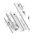
- FIG. 7 is a perspective view of the elongated body portion of the surgical instrument shown with parts separated;
- FIG. 8 is a perspective view of a bushing shown in FIG. 7 ;
- FIG. 9 is a cut-away perspective view of the locking mechanism taken along line 9 - 9 of FIG. 4 ;
- FIG. 10 is an enlarged view of the indicated area of detail shown in FIG. 9 ;
- FIGS. 11 and 12 are longitudinal cross-sectional views of a portion of the locking mechanism during different stages of assembly of a first link.
- proximal refers to that part or component closer to the user or operator, e.g., surgeon or physician
- distal refers to that part or component farther away from the user.
- a surgical stapling instrument of the present disclosure is indicated as reference numeral 10 in FIG. 1 .
- the depicted surgical instrument fires staples, but it may be adapted to fire any other suitable fastener such as clips and two-part fasteners.
- any other suitable fastener such as clips and two-part fasteners.
- the figures depict a linear fastener-applying surgical instrument other types of endoscopic surgical instruments are encompassed by the present disclosure and are usable with the disclosed bushing 460 .
- further details of endoscopic forceps are described in commonly-owned U.S. Patent Publication No. 2010/0179540 to Marczyk et al., and U.S. patent application Ser. No. 12/718,143 to Marczyk et al., the entire contents of each of which are hereby incorporated by reference herein.
- surgical instrument 10 includes a handle assembly 20 including a movable handle 22 , an elongated or endoscopic portion 30 extending distally from the handle assembly 20 and defining a longitudinal axis “A,” and a loading unit 500 attachable to endoscopic portion 30 , e.g., to allow surgical instrument 10 to have greater versatility.
- Loading unit 500 includes a proximal portion 41 and an end effector 40 , including a cartridge 50 and an anvil 60 , disposed adjacent the proximal portion 41 .
- the loading unit 500 may be configured for a single use, and/or may be configured to be used more than once. Examples of loading units for use with a surgical stapling instrument are disclosed in commonly-owned U.S. Pat. No. 5,752,644 to Bolanos et al., the entire contents of which are hereby incorporated by reference herein.
- the movable handle 22 is actuatable (e.g., through successive strokes) to cause distal advancement of a drive rod or control rod 52 , such that the drive rod engages a portion of a drive assembly, which forces at least a portion of the drive assembly to translate distally.
- actuation of movable handle 22 causes distal advancement of the drive rod are explained in U.S. Pat. No.
- Distal movement of the drive rod, and in particular, a dynamic clamping member engaged therewith, causes an actuation sled to move distally through the cartridge 50 , which causes cam wedges of the actuation sled to sequentially engage pushers to move pushers vertically within retention slots and eject fasteners towards the anvil 60 .
- a cutting edge of the dynamic clamping member severs the fastened tissue as the cutting edge travels distally through a slot of the cartridge 50 .
- instrument 10 also includes a locking mechanism 400 for preventing operation of instrument 10 before a loading unit 500 has been engaged with elongated portion 30 of instrument 10 .
- Locking mechanism 400 includes a first link 402 , a bushing 460 , a connecting member or connecting tube 406 , and an articulation locking member 408 .
- Bushing 460 includes a body portion 470 and a finger 480 extending distally therefrom.
- First link 402 includes a plate-like member which is supported between control rod 52 and an inner body portion 232 of elongated portion 30 of the instrument 10 on a flat surface 53 which is ground into control rod 52 (see FIG. 10 ).
- first link 402 includes an engagement structure 414 (e.g., an opening, slot, detent, etc.) which is dimensioned to receive a tongue 482 depending from finger 480 of bushing 460 .
- Bushing 460 , link 402 , and flat surface 53 on control rod 52 function together to prevent control rod 52 from rotating in outer tube 230 . This ensures proper rotational alignment between a hook 242 within outer tube 230 and a notch 248 in control rod 52 (see FIG. 10 , for example).
- Body portion 470 of bushing 460 is disposed proximally of first link 402 and bushing 460 is radially positioned between outer tube 230 and release link 202 . Additionally, body portion 470 of bushing 460 includes an aperture 462 extending longitudinally therethrough. Aperture 462 is dimensioned and configured to allow a portion of control rod 52 to longitudinally slide therethrough. That is, bushing 460 is slidingly positioned about control rod 52 .
- Finger 480 of bushing 460 is configured to mechanically engage first link 402 .
- tongue 482 of finger 480 is configured for reception at least partially within (or through) engagement structure 414 of first link 402 .
- finger 480 is configured to flex with respect to body portion 470 . More specifically, finger 480 is able to move away from longitudinal axis “A.” With particular reference to FIGS. 11 and 12 , the flexibility of finger 480 facilitates the assembly of instrument 10 , e.g., locking mechanism 400 .
- first link 402 (shown at an angle with respect to the longitudinal axis “A”) causes a proximal end 402 b of first link 402 to engage tongue 482 , and in particular an angled portion 483 thereof.
- engagement between first link 402 and angled portion 483 of tongue 482 causes finger 480 to flex away from the longitudinal axis “A,” thus allowing or facilitating continued proximal movement of first link 402 .
- First link 402 is able to continue to advance proximally until proximal end 402 b of first link 402 contacts a distal surface 474 of body portion 470 of bushing 460 .
- a proximal edge 414 a of engagement structure 414 of first link 402 has moved proximally past tongue 482 , thus allowing tongue 482 to move toward the longitudinal axis “A” (i.e., toward its biased position parallel with the longitudinal axis “A”) and at least partially within engagement structure 414 .
- first link 402 and bushing 460 are mechanically engaged, such that longitudinal movement of either of these two components causes a corresponding longitudinal movement of the other component. Further, the engagement between bushing 460 and first link 402 prevents longitudinal translation of first link 402 upon longitudinal translation of control rod 52 .
- the proximal end 402 b of first link 402 is configured to contact (i.e., abuts or is axially movable into contact with) a distal surface 474 of body portion 470 of bushing 460 .
- a proximal surface 476 of body portion 470 of bushing 460 is configured to contact (i.e., abuts or is axially movable into contact with) a distal end 406 b of a wall of connecting tube 406 .
- proximal movement of first link 402 causes corresponding proximal movement of bushing 460 and connecting tube 406 , during loading of loading unit 500 , for example.
- distal movement of connecting tube 406 causes corresponding distal movement of bushing 460 and first link 402 , during firing of the instrument, for example.
- the transverse dimension (i.e., along the y-axis in FIG. 8 ) of a contacting portion of the proximal surface 476 of body portion 470 of bushing 460 is between about 2 to about 10 times larger than the distal end 406 b of a wall of connecting tube 406
- the transverse dimension (i.e., along the y-axis in FIG. 8 ) of a contacting portion of the distal surface 474 of body portion 470 of bushing 460 is between about 1 to about 3 times larger than the proximal end 402 b of first link 402 .
- bushing 460 provides a robust engagement between first link 402 and connecting tube 406 . It is further envisioned that a surgical instrument without bushing 460 can be modified (e.g., by shortening the length of first link 402 (e.g., adjacent its proximal end 402 b ) and/or by shortening the length of connecting tube 406 (e.g., adjacent its distal end 406 b )) to accommodate the disclosed bushing 460 .
- bushing 460 includes a step 490 disposed on finger 480 .
- step 490 is configured to abut or approximate an inner surface of outer tube 230 .
- the limited space (or lack of space) between step 490 and the inner surface of outer tube 230 limits the amount of transverse travel that is possible between bushing 460 and outer tube 230 .
- step 490 helps ensure finger 480 does not flex away from control rod 52 during use of instrument 10 .
- step 490 helps ensure engagement between tongue 482 and engagement structure 414 of first link 302 .
- connecting tube 406 is slidably positioned about control rod 52 and has a proximal end 406 a which abuts a distal face 408 a of locking member 408 .
- Locking member 408 is also slidably positioned about control rod 52 .
- first link 402 e.g., when loading unit 500 is being loaded
- locking member 408 is also moved proximally to allow distal translation of control rod 52 .
- articulation mechanism 300 is illustrated and is configured to articulate an articulatable loading unit.
- loading unit 500 FIG. 1
- instrument 10 may be configured as a cross-compatible device that is usable with articulating loading units as well as non-articulating loading units. When used with a non-articulating loading unit, articulation assembly 300 would simply be inoperable.
- Articulation mechanism 300 includes articulation lever 16 , a mechanism cover 320 , biasing members 322 , an upper clutch 324 , a lower clutch 326 , a main shaft 328 , and a translation member 330 .
- Lower clutch 326 is rotatably fixed and defines a central throughbore which is dimensioned to receive main shaft 328 .
- Upper clutch 324 is rotatably fixed to main shaft 328 and includes a plurality of spaced projections which are received within serrations of lower clutch 326 .
- Biasing members 322 urge upper clutch 324 into engagement with lower clutch 326 to releasably secure articulation mechanism 300 in a fixed position and, thus, to releasably secure the articulatable loading unit at a fixed angle of articulation.
- Main shaft 328 includes a cam member 364 , which is configured for sliding reception within a cam slot of translation member 330 .
- cam member 364 is rotated about an axis defined by main shaft 328 .
- cam member 364 is driven in rotation, translation member 330 is urged to move linearly.
- Translation member 330 is configured to engage an articulation link 333 ( FIG. 7 ) of an articulatable loading unit such that linear movement of translation member 330 effects linear movement of the articulation link 333 to effect articulation of the articulatable loading unit.
- elongated body portion 30 of instrument 10 includes an outer tube 230 and an inner body portion 232 through which control rod 52 is inserted.
- Inner body 232 defines a recess 236 ( FIG. 10 ) for slidably receiving release link 202 such that release link is slidably positioned between outer tube 230 and inner body portion 232 .
- a projection 238 extending radially outwardly from body 232 extends into rectangular opening 222 of transverse extension 218 of release link 202 ( FIG. 7 ).
- a spring 240 is positioned within rectangular opening 222 between projection 238 and a distal end of opening 222 to urge release link 202 distally.
- Hook 242 is positioned between outer tube 230 and inner body portion 232 adjacent a ramped cam surface 220 .
- Hook 242 includes an elongated body 244 having a transverse distal end 246 .
- Transverse distal end 246 is positioned adjacent a cutout 248 in control rod 52 .
- Hook 242 is urged by a biasing member 250 to a position in which distal end 246 of hook 242 is located externally of cutout 248 .
- release link 202 is moved proximally against the urging of biasing member 240 (e.g., by pulling a release button 204 ( FIGS. 1 and 2 ) proximally), cam surface 220 moves distal end 246 of hook 242 into cutout 248 of control rod 52 .
- control rod 52 is not in its retracted position shown in FIG. 10 and notch 248 is not positioned to receive distal end 246 of hook 242 , cam surface 220 will not be able to cause hook 242 to move radially inwardly and thus link 202 will not be able to move proximally. Thus, a loading unit 500 cannot be removed or installed if control rod 52 is not in the retracted position.
Abstract
Description
Claims (17)
Priority Applications (6)
| Application Number | Priority Date | Filing Date | Title |
|---|---|---|---|
| US13/871,233 US9468439B2 (en) | 2012-06-29 | 2013-04-26 | Surgical instrument and bushing |
| AU2013205793A AU2013205793B2 (en) | 2012-06-29 | 2013-05-09 | Surgical instrument and bushing |
| CA2815624A CA2815624C (en) | 2012-06-29 | 2013-05-13 | Surgical instrument and bushing |
| JP2013122860A JP6245852B2 (en) | 2012-06-29 | 2013-06-11 | Surgical instruments and bushings |
| EP13174200.9A EP2679171B1 (en) | 2012-06-29 | 2013-06-28 | Surgical instrument and bushing |
| US15/296,477 US10568623B2 (en) | 2012-06-29 | 2016-10-18 | Surgical instrument and bushing |
Applications Claiming Priority (2)
| Application Number | Priority Date | Filing Date | Title |
|---|---|---|---|
| US201261666028P | 2012-06-29 | 2012-06-29 | |
| US13/871,233 US9468439B2 (en) | 2012-06-29 | 2013-04-26 | Surgical instrument and bushing |
Related Child Applications (1)
| Application Number | Title | Priority Date | Filing Date |
|---|---|---|---|
| US15/296,477 Continuation US10568623B2 (en) | 2012-06-29 | 2016-10-18 | Surgical instrument and bushing |
Publications (2)
| Publication Number | Publication Date |
|---|---|
| US20140001232A1 US20140001232A1 (en) | 2014-01-02 |
| US9468439B2 true US9468439B2 (en) | 2016-10-18 |
Family
ID=48782880
Family Applications (2)
| Application Number | Title | Priority Date | Filing Date |
|---|---|---|---|
| US13/871,233 Active 2035-03-10 US9468439B2 (en) | 2012-06-29 | 2013-04-26 | Surgical instrument and bushing |
| US15/296,477 Active 2035-01-01 US10568623B2 (en) | 2012-06-29 | 2016-10-18 | Surgical instrument and bushing |
Family Applications After (1)
| Application Number | Title | Priority Date | Filing Date |
|---|---|---|---|
| US15/296,477 Active 2035-01-01 US10568623B2 (en) | 2012-06-29 | 2016-10-18 | Surgical instrument and bushing |
Country Status (5)
| Country | Link |
|---|---|
| US (2) | US9468439B2 (en) |
| EP (1) | EP2679171B1 (en) |
| JP (1) | JP6245852B2 (en) |
| AU (1) | AU2013205793B2 (en) |
| CA (1) | CA2815624C (en) |
Cited By (102)
| Publication number | Priority date | Publication date | Assignee | Title |
|---|---|---|---|---|
| US20170035416A1 (en) * | 2012-06-29 | 2017-02-09 | Covidien Lp | Surgical instrument and bushing |
| US10299790B2 (en) | 2017-03-03 | 2019-05-28 | Covidien Lp | Adapter with centering mechanism for articulation joint |
| US10390826B2 (en) | 2017-05-08 | 2019-08-27 | Covidien Lp | Surgical stapling device with elongated tool assembly and methods of use |
| US10420551B2 (en) | 2017-05-30 | 2019-09-24 | Covidien Lp | Authentication and information system for reusable surgical instruments |
| US10463371B2 (en) | 2016-11-29 | 2019-11-05 | Covidien Lp | Reload assembly with spent reload indicator |
| US10478185B2 (en) | 2017-06-02 | 2019-11-19 | Covidien Lp | Tool assembly with minimal dead space |
| US10492784B2 (en) | 2016-11-08 | 2019-12-03 | Covidien Lp | Surgical tool assembly with compact firing assembly |
| US10512461B2 (en) | 2014-05-15 | 2019-12-24 | Covidien Lp | Surgical fastener applying apparatus |
| US10517589B2 (en) | 2017-05-05 | 2019-12-31 | Covidien Lp | Surgical staples with expandable backspan |
| US10561419B2 (en) | 2016-05-04 | 2020-02-18 | Covidien Lp | Powered end effector assembly with pivotable channel |
| US10603035B2 (en) | 2017-05-02 | 2020-03-31 | Covidien Lp | Surgical loading unit including an articulating end effector |
| US10624636B2 (en) | 2017-08-23 | 2020-04-21 | Covidien Lp | Surgical stapling device with floating staple cartridge |
| US10660623B2 (en) | 2016-01-15 | 2020-05-26 | Covidien Lp | Centering mechanism for articulation joint |
| US10660641B2 (en) | 2017-03-16 | 2020-05-26 | Covidien Lp | Adapter with centering mechanism for articulation joint |
| US10709901B2 (en) | 2017-01-05 | 2020-07-14 | Covidien Lp | Implantable fasteners, applicators, and methods for brachytherapy |
| US10736631B2 (en) | 2018-08-07 | 2020-08-11 | Covidien Lp | End effector with staple cartridge ejector |
| US10806452B2 (en) | 2017-08-24 | 2020-10-20 | Covidien Lp | Loading unit for a surgical stapling instrument |
| US10849621B2 (en) | 2017-02-23 | 2020-12-01 | Covidien Lp | Surgical stapler with small diameter endoscopic portion |
| US10849622B2 (en) | 2018-06-21 | 2020-12-01 | Covidien Lp | Articulated stapling with fire lock |
| US10849620B2 (en) | 2018-09-14 | 2020-12-01 | Covidien Lp | Connector mechanisms for surgical stapling instruments |
| US10863987B2 (en) | 2017-11-16 | 2020-12-15 | Covidien Lp | Surgical instrument with imaging device |
| US10912563B2 (en) | 2019-01-02 | 2021-02-09 | Covidien Lp | Stapling device including tool assembly stabilizing member |
| US10925603B2 (en) | 2017-11-14 | 2021-02-23 | Covidien Lp | Reload with articulation stabilization system |
| US10945732B2 (en) | 2018-01-17 | 2021-03-16 | Covidien Lp | Surgical stapler with self-returning assembly |
| US10952767B2 (en) | 2017-02-06 | 2021-03-23 | Covidien Lp | Connector clip for securing an introducer to a surgical fastener applying apparatus |
| US10966717B2 (en) | 2016-01-07 | 2021-04-06 | Covidien Lp | Surgical fastener apparatus |
| US11090051B2 (en) | 2018-10-23 | 2021-08-17 | Covidien Lp | Surgical stapling device with floating staple cartridge |
| US11109862B2 (en) | 2019-12-12 | 2021-09-07 | Covidien Lp | Surgical stapling device with flexible shaft |
| US11123068B2 (en) | 2019-11-08 | 2021-09-21 | Covidien Lp | Surgical staple cartridge |
| US11191537B1 (en) | 2020-05-12 | 2021-12-07 | Covidien Lp | Stapling device with continuously parallel jaws |
| US11191538B1 (en) | 2020-06-08 | 2021-12-07 | Covidien Lp | Surgical stapling device with parallel jaw closure |
| US11224424B2 (en) | 2019-08-02 | 2022-01-18 | Covidien Lp | Linear stapling device with vertically movable knife |
| US11241228B2 (en) | 2019-04-05 | 2022-02-08 | Covidien Lp | Surgical instrument including an adapter assembly and an articulating surgical loading unit |
| US11246593B2 (en) | 2020-03-06 | 2022-02-15 | Covidien Lp | Staple cartridge |
| US11259808B2 (en) | 2019-03-13 | 2022-03-01 | Covidien Lp | Tool assemblies with a gap locking member |
| US11266402B2 (en) | 2020-07-30 | 2022-03-08 | Covidien Lp | Sensing curved tip for surgical stapling instruments |
| US11278282B2 (en) | 2020-01-31 | 2022-03-22 | Covidien Lp | Stapling device with selective cutting |
| US11284892B2 (en) | 2019-04-01 | 2022-03-29 | Covidien Lp | Loading unit and adapter with modified coupling assembly |
| US11284893B2 (en) | 2019-04-02 | 2022-03-29 | Covidien Lp | Stapling device with articulating tool assembly |
| US11317911B2 (en) | 2020-03-10 | 2022-05-03 | Covidien Lp | Tool assembly with replaceable cartridge assembly |
| US11324500B2 (en) | 2020-06-30 | 2022-05-10 | Covidien Lp | Surgical stapling device |
| US11324502B2 (en) | 2017-05-02 | 2022-05-10 | Covidien Lp | Surgical loading unit including an articulating end effector |
| US11331098B2 (en) | 2020-04-01 | 2022-05-17 | Covidien Lp | Sled detection device |
| US11344297B2 (en) | 2019-02-28 | 2022-05-31 | Covidien Lp | Surgical stapling device with independently movable jaws |
| US11344301B2 (en) | 2020-03-02 | 2022-05-31 | Covidien Lp | Surgical stapling device with replaceable reload assembly |
| US11344302B2 (en) | 2020-03-05 | 2022-05-31 | Covidien Lp | Articulation mechanism for surgical stapling device |
| US11350915B2 (en) | 2017-02-23 | 2022-06-07 | Covidien Lp | Surgical stapler with small diameter endoscopic portion |
| US11357505B2 (en) | 2020-03-10 | 2022-06-14 | Covidien Lp | Surgical stapling apparatus with firing lockout mechanism |
| US11369371B2 (en) | 2018-03-02 | 2022-06-28 | Covidien Lp | Surgical stapling instrument |
| US11395654B2 (en) | 2020-08-07 | 2022-07-26 | Covidien Lp | Surgical stapling device with articulation braking assembly |
| US11406385B2 (en) | 2019-10-11 | 2022-08-09 | Covidien Lp | Stapling device with a gap locking member |
| US11406384B2 (en) | 2020-10-05 | 2022-08-09 | Covidien Lp | Stapling device with drive assembly stop member |
| US11406387B2 (en) | 2020-05-12 | 2022-08-09 | Covidien Lp | Surgical stapling device with replaceable staple cartridge |
| US11406383B2 (en) | 2020-03-17 | 2022-08-09 | Covidien Lp | Fire assisted powered EGIA handle |
| US11426159B2 (en) | 2020-04-01 | 2022-08-30 | Covidien Lp | Sled detection device |
| US11439392B2 (en) | 2020-08-03 | 2022-09-13 | Covidien Lp | Surgical stapling device and fastener for pathological exam |
| US11446028B2 (en) | 2020-07-09 | 2022-09-20 | Covidien Lp | Tool assembly with pivotable clamping beam |
| US11452524B2 (en) | 2020-01-31 | 2022-09-27 | Covidien Lp | Surgical stapling device with lockout |
| US11497495B2 (en) | 2021-03-31 | 2022-11-15 | Covidien Lp | Continuous stapler strip for use with a surgical stapling device |
| US11504117B2 (en) | 2020-04-02 | 2022-11-22 | Covidien Lp | Hand-held surgical instruments |
| US11510673B1 (en) | 2021-05-25 | 2022-11-29 | Covidien Lp | Powered stapling device with manual retraction |
| US11510669B2 (en) | 2020-09-29 | 2022-11-29 | Covidien Lp | Hand-held surgical instruments |
| US11517305B2 (en) | 2020-07-09 | 2022-12-06 | Covidien Lp | Contoured staple pusher |
| US11517313B2 (en) | 2021-01-27 | 2022-12-06 | Covidien Lp | Surgical stapling device with laminated drive member |
| US11534167B2 (en) | 2020-05-28 | 2022-12-27 | Covidien Lp | Electrotaxis-conducive stapling |
| US11540831B1 (en) | 2021-08-12 | 2023-01-03 | Covidien Lp | Staple cartridge with actuation sled detection |
| US11553914B2 (en) | 2020-12-22 | 2023-01-17 | Covidien Lp | Surgical stapling device with parallel jaw closure |
| US11576674B2 (en) | 2020-10-06 | 2023-02-14 | Covidien Lp | Surgical stapling device with articulation lock assembly |
| US11576671B1 (en) | 2021-08-20 | 2023-02-14 | Covidien Lp | Small diameter linear surgical stapling apparatus |
| US11576675B2 (en) | 2021-06-07 | 2023-02-14 | Covidien Lp | Staple cartridge with knife |
| US11576670B2 (en) | 2021-05-06 | 2023-02-14 | Covidien Lp | Surgical stapling device with optimized drive assembly |
| US11602344B2 (en) | 2021-06-30 | 2023-03-14 | Covidien Lp | Surgical stapling apparatus with firing lockout assembly |
| US11602342B2 (en) | 2020-08-27 | 2023-03-14 | Covidien Lp | Surgical stapling device with laser probe |
| US11617579B2 (en) | 2021-06-29 | 2023-04-04 | Covidien Lp | Ultra low profile surgical stapling instrument for tissue resections |
| US11653922B2 (en) | 2021-09-29 | 2023-05-23 | Covidien Lp | Surgical stapling device with firing lockout mechanism |
| US11660092B2 (en) | 2020-09-29 | 2023-05-30 | Covidien Lp | Adapter for securing loading units to handle assemblies of surgical stapling instruments |
| US11660094B2 (en) | 2021-09-29 | 2023-05-30 | Covidien Lp | Surgical fastening instrument with two-part surgical fasteners |
| US11666330B2 (en) | 2021-04-05 | 2023-06-06 | Covidien Lp | Surgical stapling device with lockout mechanism |
| US11678878B2 (en) | 2020-09-16 | 2023-06-20 | Covidien Lp | Articulation mechanism for surgical stapling device |
| US11696755B2 (en) | 2021-05-19 | 2023-07-11 | Covidien Lp | Surgical stapling device with reload assembly removal lockout |
| US11701119B2 (en) | 2021-05-26 | 2023-07-18 | Covidien Lp | Powered stapling device with rack release |
| US11707275B2 (en) | 2021-06-29 | 2023-07-25 | Covidien Lp | Asymmetrical surgical stapling device |
| US11707277B2 (en) | 2021-08-20 | 2023-07-25 | Covidien Lp | Articulating surgical stapling apparatus with pivotable knife bar guide assembly |
| US11707278B2 (en) | 2020-03-06 | 2023-07-25 | Covidien Lp | Surgical stapler tool assembly to minimize bleeding |
| US11707274B2 (en) | 2019-12-06 | 2023-07-25 | Covidien Lp | Articulating mechanism for surgical instrument |
| US11717300B2 (en) | 2021-03-11 | 2023-08-08 | Covidien Lp | Surgical stapling apparatus with integrated visualization |
| US11737774B2 (en) | 2020-12-04 | 2023-08-29 | Covidien Lp | Surgical instrument with articulation assembly |
| US11737747B2 (en) | 2019-12-17 | 2023-08-29 | Covidien Lp | Hand-held surgical instruments |
| US11744582B2 (en) | 2021-01-05 | 2023-09-05 | Covidien Lp | Surgical stapling device with firing lockout mechanism |
| US11759206B2 (en) | 2021-01-05 | 2023-09-19 | Covidien Lp | Surgical stapling device with firing lockout mechanism |
| US11759207B2 (en) | 2021-01-27 | 2023-09-19 | Covidien Lp | Surgical stapling apparatus with adjustable height clamping member |
| US11771423B2 (en) | 2021-05-25 | 2023-10-03 | Covidien Lp | Powered stapling device with manual retraction |
| US11779334B2 (en) | 2021-08-19 | 2023-10-10 | Covidien Lp | Surgical stapling device including a manual retraction assembly |
| US11812956B2 (en) | 2021-05-18 | 2023-11-14 | Covidien Lp | Dual firing radial stapling device |
| US11819200B2 (en) | 2020-12-15 | 2023-11-21 | Covidien Lp | Surgical instrument with articulation assembly |
| US11844517B2 (en) | 2020-06-25 | 2023-12-19 | Covidien Lp | Linear stapling device with continuously parallel jaws |
| US11849949B2 (en) | 2021-09-30 | 2023-12-26 | Covidien Lp | Surgical stapling device with firing lockout member |
| US11864761B2 (en) | 2021-09-14 | 2024-01-09 | Covidien Lp | Surgical instrument with illumination mechanism |
| US11890014B2 (en) | 2020-02-14 | 2024-02-06 | Covidien Lp | Cartridge holder for surgical staples and having ridges in peripheral walls for gripping tissue |
| US11890007B2 (en) | 2020-11-18 | 2024-02-06 | Covidien Lp | Stapling device with flex cable and tensioning mechanism |
| US11937794B2 (en) | 2020-05-11 | 2024-03-26 | Covidien Lp | Powered handle assembly for surgical devices |
| US11944304B2 (en) | 2017-02-22 | 2024-04-02 | Covidien Lp | Loading unit for surgical instruments with low profile pushers |
Families Citing this family (24)
| Publication number | Priority date | Publication date | Assignee | Title |
|---|---|---|---|---|
| CA2987233C (en) | 2013-02-07 | 2019-10-29 | Teleflex Medical Incorporated | End effector connection and actuation systems |
| EP3065648A1 (en) | 2013-11-04 | 2016-09-14 | Covidien LP | Surgical fastener applying apparatus |
| CN110063762B (en) | 2013-11-04 | 2022-04-15 | 柯惠Lp公司 | Surgical fastener applying apparatus |
| AU2013403917A1 (en) | 2013-11-04 | 2016-04-28 | Covidien Lp | Surgical fastener applying apparatus |
| US9707005B2 (en) | 2014-02-14 | 2017-07-18 | Ethicon Llc | Lockout mechanisms for surgical devices |
| EP3256050B1 (en) * | 2015-02-15 | 2023-09-20 | Covidien LP | Universal handle for surgical instruments |
| US10039545B2 (en) | 2015-02-23 | 2018-08-07 | Covidien Lp | Double fire stapling |
| US10285698B2 (en) | 2015-02-26 | 2019-05-14 | Covidien Lp | Surgical apparatus |
| US10085749B2 (en) | 2015-02-26 | 2018-10-02 | Covidien Lp | Surgical apparatus with conductor strain relief |
| US10463368B2 (en) | 2015-04-10 | 2019-11-05 | Covidien Lp | Endoscopic stapler |
| US10349941B2 (en) | 2015-05-27 | 2019-07-16 | Covidien Lp | Multi-fire lead screw stapling device |
| US10172615B2 (en) | 2015-05-27 | 2019-01-08 | Covidien Lp | Multi-fire push rod stapling device |
| US10064622B2 (en) | 2015-07-29 | 2018-09-04 | Covidien Lp | Surgical stapling loading unit with stroke counter and lockout |
| US10045782B2 (en) | 2015-07-30 | 2018-08-14 | Covidien Lp | Surgical stapling loading unit with stroke counter and lockout |
| US10213204B2 (en) | 2015-10-02 | 2019-02-26 | Covidien Lp | Micro surgical instrument and loading unit for use therewith |
| US10772632B2 (en) | 2015-10-28 | 2020-09-15 | Covidien Lp | Surgical stapling device with triple leg staples |
| US10595864B2 (en) | 2015-11-24 | 2020-03-24 | Covidien Lp | Adapter assembly for interconnecting electromechanical surgical devices and surgical loading units, and surgical systems thereof |
| US10111660B2 (en) | 2015-12-03 | 2018-10-30 | Covidien Lp | Surgical stapler flexible distal tip |
| US10349937B2 (en) | 2016-02-10 | 2019-07-16 | Covidien Lp | Surgical stapler with articulation locking mechanism |
| US10420559B2 (en) | 2016-02-11 | 2019-09-24 | Covidien Lp | Surgical stapler with small diameter endoscopic portion |
| US11065022B2 (en) | 2016-05-17 | 2021-07-20 | Covidien Lp | Cutting member for a surgical instrument |
| US11642126B2 (en) | 2016-11-04 | 2023-05-09 | Covidien Lp | Surgical stapling apparatus with tissue pockets |
| US10631857B2 (en) | 2016-11-04 | 2020-04-28 | Covidien Lp | Loading unit for surgical instruments with low profile pushers |
| US11197673B2 (en) | 2018-10-30 | 2021-12-14 | Covidien Lp | Surgical stapling instruments and end effector assemblies thereof |
Citations (17)
| Publication number | Priority date | Publication date | Assignee | Title |
|---|---|---|---|---|
| US5865361A (en) * | 1997-09-23 | 1999-02-02 | United States Surgical Corporation | Surgical stapling apparatus |
| US6032849A (en) | 1995-08-28 | 2000-03-07 | United States Surgical | Surgical stapler |
| WO2003030743A2 (en) | 2001-10-05 | 2003-04-17 | Tyco Healthcare Group Lp | Surgical stapling device |
| EP2090253A2 (en) | 2008-02-15 | 2009-08-19 | Ethicon Endo-Surgery, Inc. | Disposable loading units for a surgical cutting and stapling instrument |
| EP2090254A1 (en) | 2008-02-14 | 2009-08-19 | Ethicon Endo-Surgery, Inc. | Articulatable loading units for surgical stapling and cutting instruments |
| US20090206132A1 (en) | 2008-02-15 | 2009-08-20 | Ethicon Endo-Surgery, Inc. | Feedback and lockout mechanism for surgical instrument |
| US20090206131A1 (en) | 2008-02-15 | 2009-08-20 | Ethicon Endo-Surgery, Inc. | End effector coupling arrangements for a surgical cutting and stapling instrument |
| US7815090B2 (en) | 2006-10-06 | 2010-10-19 | Tyco Healthcare Group Lp | Surgical instrument with articulating tool assembly |
| US7819298B2 (en) | 2008-02-14 | 2010-10-26 | Ethicon Endo-Surgery, Inc. | Surgical stapling apparatus with control features operable with one hand |
| US7819297B2 (en) | 2008-02-14 | 2010-10-26 | Ethicon Endo-Surgery, Inc. | Surgical stapling apparatus with reprocessible handle assembly |
| US7819296B2 (en) | 2008-02-14 | 2010-10-26 | Ethicon Endo-Surgery, Inc. | Surgical stapling apparatus with retractable firing systems |
| US7861906B2 (en) | 2008-02-14 | 2011-01-04 | Ethicon Endo-Surgery, Inc. | Surgical stapling apparatus with articulatable components |
| US7866527B2 (en) | 2008-02-14 | 2011-01-11 | Ethicon Endo-Surgery, Inc. | Surgical stapling apparatus with interlockable firing system |
| US7959051B2 (en) | 2008-02-15 | 2011-06-14 | Ethicon Endo-Surgery, Inc. | Closure systems for a surgical cutting and stapling instrument |
| US7980443B2 (en) | 2008-02-15 | 2011-07-19 | Ethicon Endo-Surgery, Inc. | End effectors for a surgical cutting and stapling instrument |
| EP2583630A2 (en) | 2011-10-17 | 2013-04-24 | Covidien LP | Surgical stapling apparatus |
| US20140001233A1 (en) * | 2012-06-29 | 2014-01-02 | Covidien Lp | Surgical instrument and bushing |
Family Cites Families (4)
| Publication number | Priority date | Publication date | Assignee | Title |
|---|---|---|---|---|
| US5752644A (en) | 1995-07-11 | 1998-05-19 | United States Surgical Corporation | Disposable loading unit for surgical stapler |
| US8475453B2 (en) | 2006-10-06 | 2013-07-02 | Covidien Lp | Endoscopic vessel sealer and divider having a flexible articulating shaft |
| US8011554B2 (en) | 2008-01-09 | 2011-09-06 | Tyco Healthcare Group, Lp | Raised boss for staple guide |
| US9468439B2 (en) * | 2012-06-29 | 2016-10-18 | Covidien Lp | Surgical instrument and bushing |
-
2013
- 2013-04-26 US US13/871,233 patent/US9468439B2/en active Active
- 2013-05-09 AU AU2013205793A patent/AU2013205793B2/en not_active Ceased
- 2013-05-13 CA CA2815624A patent/CA2815624C/en active Active
- 2013-06-11 JP JP2013122860A patent/JP6245852B2/en active Active
- 2013-06-28 EP EP13174200.9A patent/EP2679171B1/en active Active
-
2016
- 2016-10-18 US US15/296,477 patent/US10568623B2/en active Active
Patent Citations (24)
| Publication number | Priority date | Publication date | Assignee | Title |
|---|---|---|---|---|
| US6032849A (en) | 1995-08-28 | 2000-03-07 | United States Surgical | Surgical stapler |
| US5865361A (en) * | 1997-09-23 | 1999-02-02 | United States Surgical Corporation | Surgical stapling apparatus |
| WO2003030743A2 (en) | 2001-10-05 | 2003-04-17 | Tyco Healthcare Group Lp | Surgical stapling device |
| US7815090B2 (en) | 2006-10-06 | 2010-10-19 | Tyco Healthcare Group Lp | Surgical instrument with articulating tool assembly |
| US7815091B2 (en) | 2006-10-06 | 2010-10-19 | Tyco Healthcare Group Lp | Surgical instrument with articulating tool assembly |
| EP2090254A1 (en) | 2008-02-14 | 2009-08-19 | Ethicon Endo-Surgery, Inc. | Articulatable loading units for surgical stapling and cutting instruments |
| US20110068148A1 (en) | 2008-02-14 | 2011-03-24 | Ethicon Endo-Surgery, Inc. | Surgical stapling apparatus with interlockable firing system |
| US20110132962A1 (en) | 2008-02-14 | 2011-06-09 | Ethicon Endo-Surgery, Inc. | Surgical stapling apparatus with control features |
| US20110006099A1 (en) | 2008-02-14 | 2011-01-13 | Ethicon Endo-Surgery, Inc. | Surgical stapling apparatus with control features operable with one hand |
| US20090206133A1 (en) | 2008-02-14 | 2009-08-20 | Ethicon Endo-Surgery, Inc. | Articulatable loading units for surgical stapling and cutting instruments |
| US7866527B2 (en) | 2008-02-14 | 2011-01-11 | Ethicon Endo-Surgery, Inc. | Surgical stapling apparatus with interlockable firing system |
| US7819298B2 (en) | 2008-02-14 | 2010-10-26 | Ethicon Endo-Surgery, Inc. | Surgical stapling apparatus with control features operable with one hand |
| US7819297B2 (en) | 2008-02-14 | 2010-10-26 | Ethicon Endo-Surgery, Inc. | Surgical stapling apparatus with reprocessible handle assembly |
| US7819296B2 (en) | 2008-02-14 | 2010-10-26 | Ethicon Endo-Surgery, Inc. | Surgical stapling apparatus with retractable firing systems |
| US7861906B2 (en) | 2008-02-14 | 2011-01-04 | Ethicon Endo-Surgery, Inc. | Surgical stapling apparatus with articulatable components |
| US20090206137A1 (en) | 2008-02-15 | 2009-08-20 | Ethicon Endo-Surgery, Inc. | Disposable loading units for a surgical cutting and stapling instrument |
| US20090206131A1 (en) | 2008-02-15 | 2009-08-20 | Ethicon Endo-Surgery, Inc. | End effector coupling arrangements for a surgical cutting and stapling instrument |
| US20090206132A1 (en) | 2008-02-15 | 2009-08-20 | Ethicon Endo-Surgery, Inc. | Feedback and lockout mechanism for surgical instrument |
| US20110132964A1 (en) | 2008-02-15 | 2011-06-09 | Ethicon Endo-Surgery, Inc. | End effector coupling arrangements for a surgical cutting and stapling instrument |
| EP2090253A2 (en) | 2008-02-15 | 2009-08-19 | Ethicon Endo-Surgery, Inc. | Disposable loading units for a surgical cutting and stapling instrument |
| US7959051B2 (en) | 2008-02-15 | 2011-06-14 | Ethicon Endo-Surgery, Inc. | Closure systems for a surgical cutting and stapling instrument |
| US7980443B2 (en) | 2008-02-15 | 2011-07-19 | Ethicon Endo-Surgery, Inc. | End effectors for a surgical cutting and stapling instrument |
| EP2583630A2 (en) | 2011-10-17 | 2013-04-24 | Covidien LP | Surgical stapling apparatus |
| US20140001233A1 (en) * | 2012-06-29 | 2014-01-02 | Covidien Lp | Surgical instrument and bushing |
Non-Patent Citations (1)
| Title |
|---|
| European Search Report EP 13 17 4200 dated Oct. 4, 2013. |
Cited By (136)
| Publication number | Priority date | Publication date | Assignee | Title |
|---|---|---|---|---|
| US10568623B2 (en) * | 2012-06-29 | 2020-02-25 | Covidien Lp | Surgical instrument and bushing |
| US20170035416A1 (en) * | 2012-06-29 | 2017-02-09 | Covidien Lp | Surgical instrument and bushing |
| US10512461B2 (en) | 2014-05-15 | 2019-12-24 | Covidien Lp | Surgical fastener applying apparatus |
| US11497497B2 (en) | 2014-05-15 | 2022-11-15 | Covidien Lp | Surgical fastener applying apparatus |
| US10966717B2 (en) | 2016-01-07 | 2021-04-06 | Covidien Lp | Surgical fastener apparatus |
| US10660623B2 (en) | 2016-01-15 | 2020-05-26 | Covidien Lp | Centering mechanism for articulation joint |
| US10561419B2 (en) | 2016-05-04 | 2020-02-18 | Covidien Lp | Powered end effector assembly with pivotable channel |
| US10492784B2 (en) | 2016-11-08 | 2019-12-03 | Covidien Lp | Surgical tool assembly with compact firing assembly |
| US11534161B2 (en) | 2016-11-08 | 2022-12-27 | Covidien Lp | Surgical tool assembly with compact firing assembly |
| US10463371B2 (en) | 2016-11-29 | 2019-11-05 | Covidien Lp | Reload assembly with spent reload indicator |
| US11324505B2 (en) | 2016-11-29 | 2022-05-10 | Covidien Lp | Reload assembly with spent reload indicator |
| US10709901B2 (en) | 2017-01-05 | 2020-07-14 | Covidien Lp | Implantable fasteners, applicators, and methods for brachytherapy |
| US11559700B2 (en) | 2017-01-05 | 2023-01-24 | Covidien Lp | Implantable fasteners, applicators, and methods for brachytherapy |
| US10952767B2 (en) | 2017-02-06 | 2021-03-23 | Covidien Lp | Connector clip for securing an introducer to a surgical fastener applying apparatus |
| US11944304B2 (en) | 2017-02-22 | 2024-04-02 | Covidien Lp | Loading unit for surgical instruments with low profile pushers |
| US11350915B2 (en) | 2017-02-23 | 2022-06-07 | Covidien Lp | Surgical stapler with small diameter endoscopic portion |
| US10849621B2 (en) | 2017-02-23 | 2020-12-01 | Covidien Lp | Surgical stapler with small diameter endoscopic portion |
| US11786247B2 (en) | 2017-02-23 | 2023-10-17 | Covidien Lp | Surgical stapler with small diameter endoscopic portion |
| US11337697B2 (en) | 2017-03-03 | 2022-05-24 | Covidien Lp | Adapter with centering mechanism for articulation joint |
| US10667813B2 (en) | 2017-03-03 | 2020-06-02 | Covidien Lp | Adapter with centering mechanism for articulation joint |
| US10299790B2 (en) | 2017-03-03 | 2019-05-28 | Covidien Lp | Adapter with centering mechanism for articulation joint |
| US10660641B2 (en) | 2017-03-16 | 2020-05-26 | Covidien Lp | Adapter with centering mechanism for articulation joint |
| US10603035B2 (en) | 2017-05-02 | 2020-03-31 | Covidien Lp | Surgical loading unit including an articulating end effector |
| US11324502B2 (en) | 2017-05-02 | 2022-05-10 | Covidien Lp | Surgical loading unit including an articulating end effector |
| US11723660B2 (en) | 2017-05-02 | 2023-08-15 | Covidien Lp | Surgical loading unit including an articulating end effector |
| US10524784B2 (en) | 2017-05-05 | 2020-01-07 | Covidien Lp | Surgical staples with expandable backspan |
| US10517589B2 (en) | 2017-05-05 | 2019-12-31 | Covidien Lp | Surgical staples with expandable backspan |
| US11324498B2 (en) | 2017-05-05 | 2022-05-10 | Covidien Lp | Surgical staples with expandable backspan |
| US11317916B2 (en) | 2017-05-08 | 2022-05-03 | Covidien Lp | Surgical stapling device with elongated tool assembly and methods of use |
| US10390826B2 (en) | 2017-05-08 | 2019-08-27 | Covidien Lp | Surgical stapling device with elongated tool assembly and methods of use |
| US10420551B2 (en) | 2017-05-30 | 2019-09-24 | Covidien Lp | Authentication and information system for reusable surgical instruments |
| US11185323B2 (en) | 2017-05-30 | 2021-11-30 | Covidien Lp | Authentication and information system for reusable surgical instruments |
| US11617581B2 (en) | 2017-06-02 | 2023-04-04 | Covidien Lp | Tool assembly with minimal dead space |
| US10478185B2 (en) | 2017-06-02 | 2019-11-19 | Covidien Lp | Tool assembly with minimal dead space |
| US10624636B2 (en) | 2017-08-23 | 2020-04-21 | Covidien Lp | Surgical stapling device with floating staple cartridge |
| US10806452B2 (en) | 2017-08-24 | 2020-10-20 | Covidien Lp | Loading unit for a surgical stapling instrument |
| US10925603B2 (en) | 2017-11-14 | 2021-02-23 | Covidien Lp | Reload with articulation stabilization system |
| US11744586B2 (en) | 2017-11-16 | 2023-09-05 | Covidien Lp | Surgical instrument with imaging device |
| US10863987B2 (en) | 2017-11-16 | 2020-12-15 | Covidien Lp | Surgical instrument with imaging device |
| US10945732B2 (en) | 2018-01-17 | 2021-03-16 | Covidien Lp | Surgical stapler with self-returning assembly |
| US11369371B2 (en) | 2018-03-02 | 2022-06-28 | Covidien Lp | Surgical stapling instrument |
| US10849622B2 (en) | 2018-06-21 | 2020-12-01 | Covidien Lp | Articulated stapling with fire lock |
| US11864759B2 (en) | 2018-06-21 | 2024-01-09 | Covidien Lp | Articulated stapling with fire lock |
| US11547406B2 (en) | 2018-08-07 | 2023-01-10 | Covidien Lp | End effector with staple cartridge ejector |
| US10736631B2 (en) | 2018-08-07 | 2020-08-11 | Covidien Lp | End effector with staple cartridge ejector |
| US10849620B2 (en) | 2018-09-14 | 2020-12-01 | Covidien Lp | Connector mechanisms for surgical stapling instruments |
| US11504121B2 (en) | 2018-09-14 | 2022-11-22 | Covidien Lp | Connector mechanisms for surgical stapling instruments |
| US11090051B2 (en) | 2018-10-23 | 2021-08-17 | Covidien Lp | Surgical stapling device with floating staple cartridge |
| US11806014B2 (en) | 2018-10-23 | 2023-11-07 | Covidien Lp | Surgical stapling device with floating staple cartridge |
| US10912563B2 (en) | 2019-01-02 | 2021-02-09 | Covidien Lp | Stapling device including tool assembly stabilizing member |
| US11344297B2 (en) | 2019-02-28 | 2022-05-31 | Covidien Lp | Surgical stapling device with independently movable jaws |
| US11890011B2 (en) | 2019-03-13 | 2024-02-06 | Covidien Lp | Tool assemblies with a gap locking member |
| US11259808B2 (en) | 2019-03-13 | 2022-03-01 | Covidien Lp | Tool assemblies with a gap locking member |
| US11284892B2 (en) | 2019-04-01 | 2022-03-29 | Covidien Lp | Loading unit and adapter with modified coupling assembly |
| US11890009B2 (en) | 2019-04-01 | 2024-02-06 | Covidien Lp | Loading unit and adapter with modified coupling assembly |
| US11284893B2 (en) | 2019-04-02 | 2022-03-29 | Covidien Lp | Stapling device with articulating tool assembly |
| US11241228B2 (en) | 2019-04-05 | 2022-02-08 | Covidien Lp | Surgical instrument including an adapter assembly and an articulating surgical loading unit |
| US11925348B2 (en) | 2019-04-05 | 2024-03-12 | Covidien Lp | Surgical instrument including an adapter assembly and an articulating surgical loading unit |
| US11224424B2 (en) | 2019-08-02 | 2022-01-18 | Covidien Lp | Linear stapling device with vertically movable knife |
| US11793517B2 (en) | 2019-08-02 | 2023-10-24 | Covidien Lp | Linear stapling device with vertically movable knife |
| US11406385B2 (en) | 2019-10-11 | 2022-08-09 | Covidien Lp | Stapling device with a gap locking member |
| US11123068B2 (en) | 2019-11-08 | 2021-09-21 | Covidien Lp | Surgical staple cartridge |
| US11707274B2 (en) | 2019-12-06 | 2023-07-25 | Covidien Lp | Articulating mechanism for surgical instrument |
| US11779335B2 (en) | 2019-12-12 | 2023-10-10 | Covidien Lp | Surgical stapling device with flexible shaft |
| US11109862B2 (en) | 2019-12-12 | 2021-09-07 | Covidien Lp | Surgical stapling device with flexible shaft |
| US11737747B2 (en) | 2019-12-17 | 2023-08-29 | Covidien Lp | Hand-held surgical instruments |
| US11452524B2 (en) | 2020-01-31 | 2022-09-27 | Covidien Lp | Surgical stapling device with lockout |
| US11278282B2 (en) | 2020-01-31 | 2022-03-22 | Covidien Lp | Stapling device with selective cutting |
| US11696758B2 (en) | 2020-01-31 | 2023-07-11 | Covidien Lp | Stapling device with selective cutting |
| US11890014B2 (en) | 2020-02-14 | 2024-02-06 | Covidien Lp | Cartridge holder for surgical staples and having ridges in peripheral walls for gripping tissue |
| US11944298B2 (en) | 2020-03-02 | 2024-04-02 | Covidien Lp | Surgical stapling device with replaceable reload assembly |
| US11344301B2 (en) | 2020-03-02 | 2022-05-31 | Covidien Lp | Surgical stapling device with replaceable reload assembly |
| US11684364B2 (en) | 2020-03-05 | 2023-06-27 | Covidien Lp | Articulation mechanism for surgical stapling device |
| US11344302B2 (en) | 2020-03-05 | 2022-05-31 | Covidien Lp | Articulation mechanism for surgical stapling device |
| US11707278B2 (en) | 2020-03-06 | 2023-07-25 | Covidien Lp | Surgical stapler tool assembly to minimize bleeding |
| US11246593B2 (en) | 2020-03-06 | 2022-02-15 | Covidien Lp | Staple cartridge |
| US11737753B2 (en) | 2020-03-10 | 2023-08-29 | Covidien Lp | Surgical stapling apparatus with firing lockout mechanism |
| US11317911B2 (en) | 2020-03-10 | 2022-05-03 | Covidien Lp | Tool assembly with replaceable cartridge assembly |
| US11723656B2 (en) | 2020-03-10 | 2023-08-15 | Covidien Lp | Tool assembly with replaceable cartridge assembly |
| US11357505B2 (en) | 2020-03-10 | 2022-06-14 | Covidien Lp | Surgical stapling apparatus with firing lockout mechanism |
| US11406383B2 (en) | 2020-03-17 | 2022-08-09 | Covidien Lp | Fire assisted powered EGIA handle |
| US11701108B2 (en) | 2020-04-01 | 2023-07-18 | Covidien Lp | Sled detection device |
| US11331098B2 (en) | 2020-04-01 | 2022-05-17 | Covidien Lp | Sled detection device |
| US11426159B2 (en) | 2020-04-01 | 2022-08-30 | Covidien Lp | Sled detection device |
| US11504117B2 (en) | 2020-04-02 | 2022-11-22 | Covidien Lp | Hand-held surgical instruments |
| US11937794B2 (en) | 2020-05-11 | 2024-03-26 | Covidien Lp | Powered handle assembly for surgical devices |
| US11406387B2 (en) | 2020-05-12 | 2022-08-09 | Covidien Lp | Surgical stapling device with replaceable staple cartridge |
| US11191537B1 (en) | 2020-05-12 | 2021-12-07 | Covidien Lp | Stapling device with continuously parallel jaws |
| US11832815B2 (en) | 2020-05-12 | 2023-12-05 | Covidien Lp | Stapling device with continuously parallel jaws |
| US11534167B2 (en) | 2020-05-28 | 2022-12-27 | Covidien Lp | Electrotaxis-conducive stapling |
| US11191538B1 (en) | 2020-06-08 | 2021-12-07 | Covidien Lp | Surgical stapling device with parallel jaw closure |
| US11766256B2 (en) | 2020-06-08 | 2023-09-26 | Covidien Lp | Surgical stapling device with parallel jaw closure |
| US11844517B2 (en) | 2020-06-25 | 2023-12-19 | Covidien Lp | Linear stapling device with continuously parallel jaws |
| US11324500B2 (en) | 2020-06-30 | 2022-05-10 | Covidien Lp | Surgical stapling device |
| US11517305B2 (en) | 2020-07-09 | 2022-12-06 | Covidien Lp | Contoured staple pusher |
| US11446028B2 (en) | 2020-07-09 | 2022-09-20 | Covidien Lp | Tool assembly with pivotable clamping beam |
| US11849942B2 (en) | 2020-07-30 | 2023-12-26 | Covidien Lp | Sensing curved tip for surgical stapling instruments |
| US11266402B2 (en) | 2020-07-30 | 2022-03-08 | Covidien Lp | Sensing curved tip for surgical stapling instruments |
| US11439392B2 (en) | 2020-08-03 | 2022-09-13 | Covidien Lp | Surgical stapling device and fastener for pathological exam |
| US11395654B2 (en) | 2020-08-07 | 2022-07-26 | Covidien Lp | Surgical stapling device with articulation braking assembly |
| US11602342B2 (en) | 2020-08-27 | 2023-03-14 | Covidien Lp | Surgical stapling device with laser probe |
| US11678878B2 (en) | 2020-09-16 | 2023-06-20 | Covidien Lp | Articulation mechanism for surgical stapling device |
| US11660092B2 (en) | 2020-09-29 | 2023-05-30 | Covidien Lp | Adapter for securing loading units to handle assemblies of surgical stapling instruments |
| US11510669B2 (en) | 2020-09-29 | 2022-11-29 | Covidien Lp | Hand-held surgical instruments |
| US11406384B2 (en) | 2020-10-05 | 2022-08-09 | Covidien Lp | Stapling device with drive assembly stop member |
| US11576674B2 (en) | 2020-10-06 | 2023-02-14 | Covidien Lp | Surgical stapling device with articulation lock assembly |
| US11890007B2 (en) | 2020-11-18 | 2024-02-06 | Covidien Lp | Stapling device with flex cable and tensioning mechanism |
| US11737774B2 (en) | 2020-12-04 | 2023-08-29 | Covidien Lp | Surgical instrument with articulation assembly |
| US11819200B2 (en) | 2020-12-15 | 2023-11-21 | Covidien Lp | Surgical instrument with articulation assembly |
| US11553914B2 (en) | 2020-12-22 | 2023-01-17 | Covidien Lp | Surgical stapling device with parallel jaw closure |
| US11744582B2 (en) | 2021-01-05 | 2023-09-05 | Covidien Lp | Surgical stapling device with firing lockout mechanism |
| US11759206B2 (en) | 2021-01-05 | 2023-09-19 | Covidien Lp | Surgical stapling device with firing lockout mechanism |
| US11517313B2 (en) | 2021-01-27 | 2022-12-06 | Covidien Lp | Surgical stapling device with laminated drive member |
| US11759207B2 (en) | 2021-01-27 | 2023-09-19 | Covidien Lp | Surgical stapling apparatus with adjustable height clamping member |
| US11717300B2 (en) | 2021-03-11 | 2023-08-08 | Covidien Lp | Surgical stapling apparatus with integrated visualization |
| US11497495B2 (en) | 2021-03-31 | 2022-11-15 | Covidien Lp | Continuous stapler strip for use with a surgical stapling device |
| US11666330B2 (en) | 2021-04-05 | 2023-06-06 | Covidien Lp | Surgical stapling device with lockout mechanism |
| US11576670B2 (en) | 2021-05-06 | 2023-02-14 | Covidien Lp | Surgical stapling device with optimized drive assembly |
| US11812956B2 (en) | 2021-05-18 | 2023-11-14 | Covidien Lp | Dual firing radial stapling device |
| US11696755B2 (en) | 2021-05-19 | 2023-07-11 | Covidien Lp | Surgical stapling device with reload assembly removal lockout |
| US11510673B1 (en) | 2021-05-25 | 2022-11-29 | Covidien Lp | Powered stapling device with manual retraction |
| US11771423B2 (en) | 2021-05-25 | 2023-10-03 | Covidien Lp | Powered stapling device with manual retraction |
| US11701119B2 (en) | 2021-05-26 | 2023-07-18 | Covidien Lp | Powered stapling device with rack release |
| US11576675B2 (en) | 2021-06-07 | 2023-02-14 | Covidien Lp | Staple cartridge with knife |
| US11617579B2 (en) | 2021-06-29 | 2023-04-04 | Covidien Lp | Ultra low profile surgical stapling instrument for tissue resections |
| US11707275B2 (en) | 2021-06-29 | 2023-07-25 | Covidien Lp | Asymmetrical surgical stapling device |
| US11602344B2 (en) | 2021-06-30 | 2023-03-14 | Covidien Lp | Surgical stapling apparatus with firing lockout assembly |
| US11540831B1 (en) | 2021-08-12 | 2023-01-03 | Covidien Lp | Staple cartridge with actuation sled detection |
| US11779334B2 (en) | 2021-08-19 | 2023-10-10 | Covidien Lp | Surgical stapling device including a manual retraction assembly |
| US11576671B1 (en) | 2021-08-20 | 2023-02-14 | Covidien Lp | Small diameter linear surgical stapling apparatus |
| US11707277B2 (en) | 2021-08-20 | 2023-07-25 | Covidien Lp | Articulating surgical stapling apparatus with pivotable knife bar guide assembly |
| US11896220B2 (en) | 2021-08-20 | 2024-02-13 | Covidien Lp | Small diameter linear surgical stapling apparatus |
| US11864761B2 (en) | 2021-09-14 | 2024-01-09 | Covidien Lp | Surgical instrument with illumination mechanism |
| US11660094B2 (en) | 2021-09-29 | 2023-05-30 | Covidien Lp | Surgical fastening instrument with two-part surgical fasteners |
| US11653922B2 (en) | 2021-09-29 | 2023-05-23 | Covidien Lp | Surgical stapling device with firing lockout mechanism |
| US11849949B2 (en) | 2021-09-30 | 2023-12-26 | Covidien Lp | Surgical stapling device with firing lockout member |
Also Published As
| Publication number | Publication date |
|---|---|
| CA2815624C (en) | 2020-04-07 |
| US20140001232A1 (en) | 2014-01-02 |
| AU2013205793A1 (en) | 2014-01-16 |
| CA2815624A1 (en) | 2013-12-29 |
| AU2013205793B2 (en) | 2017-06-08 |
| JP2014008403A (en) | 2014-01-20 |
| US10568623B2 (en) | 2020-02-25 |
| EP2679171A1 (en) | 2014-01-01 |
| EP2679171B1 (en) | 2015-11-04 |
| JP6245852B2 (en) | 2017-12-13 |
| US20170035416A1 (en) | 2017-02-09 |
Similar Documents
| Publication | Publication Date | Title |
|---|---|---|
| US10568623B2 (en) | Surgical instrument and bushing | |
| US9232944B2 (en) | Surgical instrument and bushing | |
| US11375998B2 (en) | Tissue stop for surgical instrument | |
| US8348124B2 (en) | Knife bar with geared overdrive | |
| US8186558B2 (en) | Locking mechanism for use with loading units | |
| US10034666B2 (en) | Tissue stop for surgical instrument | |
| US7097089B2 (en) | Surgical stapling apparatus with locking mechanism | |
| US7172104B2 (en) | Surgical stapling apparatus | |
| US7896214B2 (en) | Tissue stop for surgical instrument | |
| EP3858259B1 (en) | Stapling device with selective cutting |
Legal Events
| Date | Code | Title | Description |
|---|---|---|---|
| AS | Assignment |
Owner name: COVIDIEN LP, MASSACHUSETTS Free format text: ASSIGNMENT OF ASSIGNORS INTEREST;ASSIGNORS:CAPPOLA, KENNETH M.;OLSON, LEE ANN;MAFFEI, FRANK C.;REEL/FRAME:030296/0190 Effective date: 20130422 |
|
| STCF | Information on status: patent grant |
Free format text: PATENTED CASE |
|
| MAFP | Maintenance fee payment |
Free format text: PAYMENT OF MAINTENANCE FEE, 4TH YEAR, LARGE ENTITY (ORIGINAL EVENT CODE: M1551); ENTITY STATUS OF PATENT OWNER: LARGE ENTITY Year of fee payment: 4 |
|
| MAFP | Maintenance fee payment |
Free format text: PAYMENT OF MAINTENANCE FEE, 8TH YEAR, LARGE ENTITY (ORIGINAL EVENT CODE: M1552); ENTITY STATUS OF PATENT OWNER: LARGE ENTITY Year of fee payment: 8 |