US9453941B2 - Road surface reflectivity detection by lidar sensor - Google Patents
Road surface reflectivity detection by lidar sensor Download PDFInfo
- Publication number
- US9453941B2 US9453941B2 US14/578,638 US201414578638A US9453941B2 US 9453941 B2 US9453941 B2 US 9453941B2 US 201414578638 A US201414578638 A US 201414578638A US 9453941 B2 US9453941 B2 US 9453941B2
- Authority
- US
- United States
- Prior art keywords
- road
- precipitation
- photodetector
- response
- travel
- Prior art date
- Legal status (The legal status is an assumption and is not a legal conclusion. Google has not performed a legal analysis and makes no representation as to the accuracy of the status listed.)
- Active, expires
Links
- 238000001514 detection method Methods 0.000 title description 11
- 238000002310 reflectometry Methods 0.000 title description 3
- 238000000034 method Methods 0.000 claims abstract description 44
- 238000001556 precipitation Methods 0.000 claims abstract description 34
- 230000004044 response Effects 0.000 claims abstract description 20
- 238000000605 extraction Methods 0.000 claims description 8
- 238000000513 principal component analysis Methods 0.000 claims description 3
- XLYOFNOQVPJJNP-UHFFFAOYSA-N water Substances O XLYOFNOQVPJJNP-UHFFFAOYSA-N 0.000 description 10
- 238000004458 analytical method Methods 0.000 description 6
- 230000000694 effects Effects 0.000 description 5
- 238000010586 diagram Methods 0.000 description 4
- 238000013528 artificial neural network Methods 0.000 description 2
- 238000004891 communication Methods 0.000 description 2
- 238000013461 design Methods 0.000 description 2
- 238000005286 illumination Methods 0.000 description 2
- 238000010801 machine learning Methods 0.000 description 2
- 230000005055 memory storage Effects 0.000 description 2
- 230000008569 process Effects 0.000 description 2
- 238000012545 processing Methods 0.000 description 2
- 238000012706 support-vector machine Methods 0.000 description 2
- 239000011800 void material Substances 0.000 description 2
- 230000004913 activation Effects 0.000 description 1
- 230000008901 benefit Effects 0.000 description 1
- 238000013480 data collection Methods 0.000 description 1
- 238000005516 engineering process Methods 0.000 description 1
- 230000002708 enhancing effect Effects 0.000 description 1
- 230000007613 environmental effect Effects 0.000 description 1
- 230000006870 function Effects 0.000 description 1
- 230000003116 impacting effect Effects 0.000 description 1
- 239000000463 material Substances 0.000 description 1
- 238000011176 pooling Methods 0.000 description 1
- 230000009467 reduction Effects 0.000 description 1
- 238000000926 separation method Methods 0.000 description 1
- 239000000126 substance Substances 0.000 description 1
- 230000000007 visual effect Effects 0.000 description 1
Images


Classifications
-
- G—PHYSICS
- G01—MEASURING; TESTING
- G01W—METEOROLOGY
- G01W1/00—Meteorology
- G01W1/10—Devices for predicting weather conditions
-
- G—PHYSICS
- G01—MEASURING; TESTING
- G01S—RADIO DIRECTION-FINDING; RADIO NAVIGATION; DETERMINING DISTANCE OR VELOCITY BY USE OF RADIO WAVES; LOCATING OR PRESENCE-DETECTING BY USE OF THE REFLECTION OR RERADIATION OF RADIO WAVES; ANALOGOUS ARRANGEMENTS USING OTHER WAVES
- G01S17/00—Systems using the reflection or reradiation of electromagnetic waves other than radio waves, e.g. lidar systems
- G01S17/88—Lidar systems specially adapted for specific applications
-
- G—PHYSICS
- G01—MEASURING; TESTING
- G01N—INVESTIGATING OR ANALYSING MATERIALS BY DETERMINING THEIR CHEMICAL OR PHYSICAL PROPERTIES
- G01N21/00—Investigating or analysing materials by the use of optical means, i.e. using sub-millimetre waves, infrared, visible or ultraviolet light
- G01N21/17—Systems in which incident light is modified in accordance with the properties of the material investigated
- G01N21/47—Scattering, i.e. diffuse reflection
- G01N21/4738—Diffuse reflection, e.g. also for testing fluids, fibrous materials
-
- G—PHYSICS
- G01—MEASURING; TESTING
- G01N—INVESTIGATING OR ANALYSING MATERIALS BY DETERMINING THEIR CHEMICAL OR PHYSICAL PROPERTIES
- G01N21/00—Investigating or analysing materials by the use of optical means, i.e. using sub-millimetre waves, infrared, visible or ultraviolet light
- G01N21/17—Systems in which incident light is modified in accordance with the properties of the material investigated
- G01N21/47—Scattering, i.e. diffuse reflection
- G01N21/49—Scattering, i.e. diffuse reflection within a body or fluid
-
- G—PHYSICS
- G01—MEASURING; TESTING
- G01N—INVESTIGATING OR ANALYSING MATERIALS BY DETERMINING THEIR CHEMICAL OR PHYSICAL PROPERTIES
- G01N21/00—Investigating or analysing materials by the use of optical means, i.e. using sub-millimetre waves, infrared, visible or ultraviolet light
- G01N21/17—Systems in which incident light is modified in accordance with the properties of the material investigated
- G01N21/55—Specular reflectivity
-
- G—PHYSICS
- G01—MEASURING; TESTING
- G01N—INVESTIGATING OR ANALYSING MATERIALS BY DETERMINING THEIR CHEMICAL OR PHYSICAL PROPERTIES
- G01N21/00—Investigating or analysing materials by the use of optical means, i.e. using sub-millimetre waves, infrared, visible or ultraviolet light
- G01N21/84—Systems specially adapted for particular applications
- G01N21/88—Investigating the presence of flaws or contamination
- G01N21/94—Investigating contamination, e.g. dust
-
- G—PHYSICS
- G01—MEASURING; TESTING
- G01S—RADIO DIRECTION-FINDING; RADIO NAVIGATION; DETERMINING DISTANCE OR VELOCITY BY USE OF RADIO WAVES; LOCATING OR PRESENCE-DETECTING BY USE OF THE REFLECTION OR RERADIATION OF RADIO WAVES; ANALOGOUS ARRANGEMENTS USING OTHER WAVES
- G01S17/00—Systems using the reflection or reradiation of electromagnetic waves other than radio waves, e.g. lidar systems
- G01S17/88—Lidar systems specially adapted for specific applications
- G01S17/95—Lidar systems specially adapted for specific applications for meteorological use
-
- G—PHYSICS
- G01—MEASURING; TESTING
- G01S—RADIO DIRECTION-FINDING; RADIO NAVIGATION; DETERMINING DISTANCE OR VELOCITY BY USE OF RADIO WAVES; LOCATING OR PRESENCE-DETECTING BY USE OF THE REFLECTION OR RERADIATION OF RADIO WAVES; ANALOGOUS ARRANGEMENTS USING OTHER WAVES
- G01S7/00—Details of systems according to groups G01S13/00, G01S15/00, G01S17/00
- G01S7/48—Details of systems according to groups G01S13/00, G01S15/00, G01S17/00 of systems according to group G01S17/00
- G01S7/4802—Details of systems according to groups G01S13/00, G01S15/00, G01S17/00 of systems according to group G01S17/00 using analysis of echo signal for target characterisation; Target signature; Target cross-section
-
- B—PERFORMING OPERATIONS; TRANSPORTING
- B60—VEHICLES IN GENERAL
- B60W—CONJOINT CONTROL OF VEHICLE SUB-UNITS OF DIFFERENT TYPE OR DIFFERENT FUNCTION; CONTROL SYSTEMS SPECIALLY ADAPTED FOR HYBRID VEHICLES; ROAD VEHICLE DRIVE CONTROL SYSTEMS FOR PURPOSES NOT RELATED TO THE CONTROL OF A PARTICULAR SUB-UNIT
- B60W40/00—Estimation or calculation of non-directly measurable driving parameters for road vehicle drive control systems not related to the control of a particular sub unit, e.g. by using mathematical models
- B60W40/02—Estimation or calculation of non-directly measurable driving parameters for road vehicle drive control systems not related to the control of a particular sub unit, e.g. by using mathematical models related to ambient conditions
- B60W40/06—Road conditions
- B60W40/068—Road friction coefficient
-
- G—PHYSICS
- G01—MEASURING; TESTING
- G01N—INVESTIGATING OR ANALYSING MATERIALS BY DETERMINING THEIR CHEMICAL OR PHYSICAL PROPERTIES
- G01N21/00—Investigating or analysing materials by the use of optical means, i.e. using sub-millimetre waves, infrared, visible or ultraviolet light
- G01N21/17—Systems in which incident light is modified in accordance with the properties of the material investigated
- G01N21/55—Specular reflectivity
- G01N2021/556—Measuring separately scattering and specular
-
- G—PHYSICS
- G01—MEASURING; TESTING
- G01N—INVESTIGATING OR ANALYSING MATERIALS BY DETERMINING THEIR CHEMICAL OR PHYSICAL PROPERTIES
- G01N21/00—Investigating or analysing materials by the use of optical means, i.e. using sub-millimetre waves, infrared, visible or ultraviolet light
- G01N21/17—Systems in which incident light is modified in accordance with the properties of the material investigated
- G01N21/55—Specular reflectivity
- G01N2021/557—Detecting specular reflective parts on sample
-
- G—PHYSICS
- G01—MEASURING; TESTING
- G01N—INVESTIGATING OR ANALYSING MATERIALS BY DETERMINING THEIR CHEMICAL OR PHYSICAL PROPERTIES
- G01N21/00—Investigating or analysing materials by the use of optical means, i.e. using sub-millimetre waves, infrared, visible or ultraviolet light
- G01N21/84—Systems specially adapted for particular applications
- G01N21/88—Investigating the presence of flaws or contamination
- G01N21/94—Investigating contamination, e.g. dust
- G01N2021/945—Liquid or solid deposits of macroscopic size on surfaces, e.g. drops, films, or clustered contaminants
-
- G—PHYSICS
- G01—MEASURING; TESTING
- G01N—INVESTIGATING OR ANALYSING MATERIALS BY DETERMINING THEIR CHEMICAL OR PHYSICAL PROPERTIES
- G01N2201/00—Features of devices classified in G01N21/00
- G01N2201/12—Circuits of general importance; Signal processing
- G01N2201/125—Digital circuitry
-
- G—PHYSICS
- G01—MEASURING; TESTING
- G01S—RADIO DIRECTION-FINDING; RADIO NAVIGATION; DETERMINING DISTANCE OR VELOCITY BY USE OF RADIO WAVES; LOCATING OR PRESENCE-DETECTING BY USE OF THE REFLECTION OR RERADIATION OF RADIO WAVES; ANALOGOUS ARRANGEMENTS USING OTHER WAVES
- G01S17/00—Systems using the reflection or reradiation of electromagnetic waves other than radio waves, e.g. lidar systems
- G01S17/88—Lidar systems specially adapted for specific applications
- G01S17/93—Lidar systems specially adapted for specific applications for anti-collision purposes
- G01S17/931—Lidar systems specially adapted for specific applications for anti-collision purposes of land vehicles
-
- Y—GENERAL TAGGING OF NEW TECHNOLOGICAL DEVELOPMENTS; GENERAL TAGGING OF CROSS-SECTIONAL TECHNOLOGIES SPANNING OVER SEVERAL SECTIONS OF THE IPC; TECHNICAL SUBJECTS COVERED BY FORMER USPC CROSS-REFERENCE ART COLLECTIONS [XRACs] AND DIGESTS
- Y02—TECHNOLOGIES OR APPLICATIONS FOR MITIGATION OR ADAPTATION AGAINST CLIMATE CHANGE
- Y02A—TECHNOLOGIES FOR ADAPTATION TO CLIMATE CHANGE
- Y02A90/00—Technologies having an indirect contribution to adaptation to climate change
- Y02A90/10—Information and communication technologies [ICT] supporting adaptation to climate change, e.g. for weather forecasting or climate simulation
Definitions
- An embodiment relates to a determination of road surface condition reflectivity of a traveled route.
- Precipitation on the road surface may result in various control issues for the vehicle.
- Snow, water, or ice on the road of travel greatly reduces the coefficient of friction between the vehicle tires and the surface of the road resulting in vehicle stability issues.
- Various known systems can sense such a condition, but require a stimulus for the detection.
- a system that senses precipitation on the road utilizing wheel slip may detect when the vehicle wheels have sudden increases in the speed of rotation of the wheel. While this operation is very good for identifying some type of precipitation on the road surface, the issue is the precipitation is already negatively impacting the vehicle operation. As a result, the vehicle must reactively make changes to the vehicle operation to reduce the effects of the precipitation already affecting the vehicle.
- Identifying a road surface condition prior to the vehicle traveling on the precipitation allows a vehicle to proactively enable various safety driving features of a vehicle or make changes to the current vehicle operations to reduce the changes of the precipitation affecting the operations of the vehicle.
- An advantage of an embodiment is the detection of a road surface condition which allows an enablement of the stability control operations to mitigate the water/snow/ice on a surface of the road.
- the system utilizes a lidar technique which determines whether a signal is received at a photodetector. A determination of whether the surface includes ice/snow/water on the road of travel is performed by analyzing signals received at the photodetector as well as an absence of signals received at the photodetector.
- Various techniques may be used to determine ice/snow/water on the surface of the surface of the road such as no response signal received, a response signal receive have an increased scattered beam as determined by analyzing the received signal using a sliding window, and detection of false objects in the return signal.
- lidar system may be used with the lidar system to enhance the probability of the road surface condition as well as the type of precipitation on the road surface.
- An embodiment contemplates a method of determining a surface condition of a road of travel.
- a light beam directed at a surface in the road of travel is transmitted utilizing a lidar system.
- a response at a photodetector of the lidar system is analyzed after transmitting the light beam.
- a determination is made whether a form of precipitation is present on the road of travel in response to analyzing the response at the photodetector.
- a precipitation indicating signal is generated in response to the determination that the ground surface includes a form of precipitation on the road of travel.
- FIG. 1 is a block diagram of a road surface condition detection system.
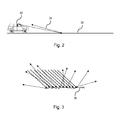
- FIG. 2 is a pictorial illustration showing reflective properties for a diffused road surface.
- FIG. 3 an enlarged view of the diffused road surface.
- FIG. 4 is a pictorial illustration showing reflective properties for a specular road surface.
- FIG. 5 is an enlarged view of the specular road surface.
- FIGS. 6 a and 6 b illustrate the respective lidar return signals illustrating an absence of lidar returns from the ground surface.
- FIG. 7 is flow diagram for a signal scattering analysis technique for detecting reflective properties of the road.
- FIG. 8 graphic illustration of a sliding window feature extraction technique.
- FIGS. 9 a and 9 b lidar return signals relating the scatting effect of the lidar beam.
- FIG. 10 is a false object detection technique used to identify reflective properties of the road.
- FIGS. 11 a and 11 b illustrate the lidar return signals indicating false objects.
- FIG. 1 a block diagram of the road surface condition detection system 10 .
- the road surface detection system 10 utilizes a lidar system 12 (e.g., Velodyne sensing system).
- Lidar is a remote sensing technology where a target is illuminated and a distance to the object is measured based on analyzing the reflected light.
- the lidar system 12 includes an illumination source 14 , such a laser. Lasers are calibrated to a respective wavelength and the laser can be set at a specified pulse length and repetition rate which controls the data collection speed.
- the lidar system 12 further includes a photodetector 16 receiving the reflected rays from the illumination source 14 .
- the lidar system 12 further includes a processor 18 for analyzing the data obtained from the photodetector 16 , and for making determinations of the reflective properties of the surface condition of the road.
- the lidar system 12 may further utilize a positioning system/navigation system for identifying an absolute position of a surface condition if the vehicle is mobile.
- a positioning system/navigation system for identifying an absolute position of a surface condition if the vehicle is mobile.
- a memory storage unit 20 may be utilized for storing information collected by the photodetector 18 .
- the memory storage unit 20 stores data utilized by a classifier for determining the road surface which will be discussed in detail later.
- Other sensing devices 22 e.g., radar, video
- radar e.g., radar, video
- a plurality of devices devices/systems 24 may be used to enable vehicle operation to assist the driver in maintaining control of the vehicle when slick road conditions are present or provide detailed information to the driver of the vehicle that informs or warns the driver of the vehicle of the upcoming road condition.
- Precipitation on the vehicle road 12 can result in a reduction of traction when driving on the wet surface.
- precipitation as defined herein may include, but is not limited to, water, ice, snow, or other substance that can cause the vehicle to lose traction.
- Precipitation disposed on the vehicle road lowers the coefficient of friction between the vehicle tires and the vehicle road, thereby reducing the traction between the vehicle tires and the vehicle road.
- Loss of traction can be mitigated by any of the following including, but not limited to, autonomous braking controls 25 using a variable braking force to minimize the precipitation formed on the braking surfaces of the braking; components warning the driver to lower the vehicle speed to one that is conducive to the environmental conditions or notification to the driver to maintain a greater stopping distance to a lead vehicle; stability traction controls 26 , speed control for deactivating or restricting the activation of cruise control functionality while precipitation is detected 27 ; driver warning output device to warn the driver of an upcoming road surface condition 28 ; or communication system for communicating to other vehicle utilizing a ad-hoc vehicle communication to forewarn other drivers of the road surface condition 29 .
- FIGS. 2 and 3 There is shown in FIGS. 2 and 3 , a vehicle 30 traveling along a road of travel 32 and directing a laser beam 34 at the surface of the road of travel 32 .
- a vehicle 30 traveling along a road of travel 32 and directing a laser beam 34 at the surface of the road of travel 32 .
- the road is diffused surface or a flat mirror-like surface, will determine how light rays are reflected from the surface of the road of travel 32 .
- FIG. 3 illustrates an enhanced view of a diffused surface 36 on the road of travel 32 .
- a diffused reflection occurs when the laser beam reflects off a surface that is not specular.
- Diffused reflection is the reflection of light from a surface such that an incident ray is reflected at many angles rather than at just one angle as in the case of specular reflection.
- the photodetector captures the return rays and is able to measure the distance from the vehicle to the point of intersection with the diffused surface. Based on an expected return versus what is or is not received, will assist in making the determination of the road surface condition.
- FIGS. 4 and 5 illustrate the vehicle 30 traveling along the road of travel 32 and directing the laser beam 34 at the surface of the road of travel 32 where the surface is a mirror-like surface 38 .
- a road surface having a mirror-like surface 38 will cause a specular reflection.
- Specular reflection is the mirror-like reflection of light from the surface where light from the incident ray coming from a single incoming direction is reflected into a single outgoing direction. As a result, the reflection ray is directed in a direction away from the vehicle since the angle of reflection is equal to the angle of incident with respect to the road surface.
- Lidar returns depend on the properties of the material from which it is reflected.
- the reflective properties of the road in wet/dry/snow regions differ significantly and thus can be detected using a lidar sensor. For example, during a rain, potholes in the road surface are filled with water and may behave like small mirrors. If a lidar beam hits the wet/water surfaces, the following effects can occur: (1) No returns back to the sensor detector; (2) scattering of the beam-signal reading is larger for data coming from reflective surface; (3) false objects can appear. The following descriptions herein will describe these respective effects and their analysis.
- FIGS. 6 a and 6 b illustrate the first scenario where there is an absence of lidar returns from the ground surface, this condition can easily be detected by tracing the laser signal in time and discovering unread data where return data is expected.
- FIG. 6 a illustrates lidar returns overlaid onto an image of the road of travel as seen by the driver
- FIG. 6 b illustrates an overhead lidar return signal plot.
- the respective lines represent the respective laser beams that are used in a specific sensor, such as an IBEO LUX sensor.
- the IBEO LUX sensor has 4 layers of lasers with the vertical field of view of 3.2 degrees and scanning rate of either of 12.5 Hz, 25 Hz, and 40 Hz; however, other sensors can be utilized that have other number of laser beams. As shown in FIG.
- element 40 illustrates water on a road surface creating a mirror like surface.
- a void 41 indicated no return signals from the transmitted signal is shown in both FIGS. 6 a and 6 b .
- the no return signal is the result of the laser beam bouncing off the mirror like surface and reflecting forward of the vehicle. As a result, a void appears in the return lidar signal.
- Such a situation may occur at the curbsides where the vehicle system could include a lane centering system that looks for curbs. While detecting curbs along the road of travel, a determination is made that there are no returns for a nearby curb line that is expected to be there.
- the surface of the curb Due to the design of the road, the surface of the curb has a negative curvature in the direction orthogonal to the direction of the road, which results in water pooling nearby the curb surface.
- the lidar beam does not return a reflection ray in certain spots and a pattern over time indicates that the pattern is broken where road and curb surfaces meet.
- the broken pattern indicates water or other mirror-like conditions on the surface of the road. Therefore, specular surfaces can be detected when no return signal is returned when expected.
- FIG. 7 represents a block diagram of an algorithmic flow to perform an analysis for signal scattering.
- a first signal is scanned by the sliding window and features are extracted per window.
- a first signal is scanned by a sliding window and features are extracted per window.
- FIG. 8 illustrates the sliding window.
- a respective window is analyzed at the i ⁇ 1 window. The window is moved and a next window is analyzed, (ith window). Successive windows are analyzed (i+1 window).
- features extracted for each window are analyzed.
- Features that are extracted include, but are not limited to, short signal statistics such as STD or any other statistics measuring deviation from a normal distribution (kurtosis, for example), FFT coefficients and their statistics.
- short signal statistics such as STD or any other statistics measuring deviation from a normal distribution (kurtosis, for example)
- FFT coefficients and their statistics.
- PCA principal component analysis
- Wavelet transform is a time-frequency-transformation utilizing a mathematical process for performing signal analysis for a signal frequency that varies over time.
- the respective features are classified.
- the last classification step can be applied by any respective classifier including, but not limited to any neural networks, support vector machines (SVM), nearest-neighbor classifiers, etc.
- Classification labels include, but are not limited to, wet regions, icy regions, dry regions, and snow regions.
- the feature extraction and classification steps may be combined into one step using deep neural networks technique.
- FIGS. 9 a and 9 b illustrate lidar return signals relating the scatting effect of the lidar beam. As shown in FIG. 9 b , while return signals are present, the geometric shape of the return signals are scattered. This type of signal is identified using signal processing and the machine learning techniques as indicated above.
- sensor data such as cameras, radar, ultrasonic
- lidar system which assists in making cooperative decisions regarding the road surface condition.
- FIG. 10 illustrates the third scenario where false objects are detected in the mirrored surface of the road.
- the lidar system transmits a beam of light onto the road of travel 32 .
- Precipitation 50 is present on the road surface.
- a light reflection on the road surface for the precipitation will have a reflected ray angle that is substantially equal to the incident ray angle.
- the precipitation 50 on the road of travel functions as a mirror-type surface having reflective properties.
- the reflected ray hits an object 52 forward of the vehicle.
- the light bouncing off the front object 52 is returned back and measured by sensor (multi-path) generating secondary echo.
- This secondary echo returns are 3D points that generates false alarm signals indicating a false/virtual object 54 .
- the false objects are considered virtual points located underground and are projected to the same point under the surface on the virtual object 54 as the real object 52 since real object 52 and the virtual object 54 are substantially the same size; however, it is expected that the intensity of the secondary pulse to be smaller due to multiple reflections.
- a ground plane is determined utilizing a robust plane fitting technique (RANSAC).
- RANSAC performs ground estimation by shifting and rotating the data to match xy plane and the ground plane.
- step 61 false object points of the virtual object that are located below the ground are identified.
- the false object points will have an underground point (z ⁇ 0). This is the same for negative objects such as potholes.
- step 62 false object points from different rays are collected by the lidar system.
- the different rays collected should be from a substantially same location when projected to the ground. The same is true for a real object, but not for certain characteristics of the road such as potholes.
- step 63 the properties identified in steps 62 and 63 are analyzed in cooperation to identify a false object detection. It is understood that the intersection between the road surface and the false objects correspond to the reflective area of road surface. These respective false object points will coincide with the real lidar points obtained from the first pulses. Detection of false objects further enables reconstruction of real objects by applying symmetry transforms of the false objects from the road surface.
- vehicle subsystems such as a camera based system may be utilized in cooperation with the lidar system for enhancing the probability that a false object below the ground plane is properly detected.
- FIGS. 11 a and 11 b illustrate the lidar return signals for the scenario where false objects are located in the signal.
- a vehicle 52 is traveling forward of the driven vehicle. Lidar return signals are present; however, respective portions of the return signals are located at a greater distance than expected.
- a lidar signal return 54 is displaced further from the where the other return signals are present. This indicates that the signal traveled a further distance to bounce off the vehicle 52 . Since the other return signals are substantially at a same location in comparison to the return signal 54 , a determination is made that the return signal indicates a false object which is indicates that a mirror-like surface is present.
- the proposed techniques described herein can be used in embodiments other than vehicle applications for determining separation between objects and backgrounds having different reflectivity, such as usage of lidar for a ship detection at sea. It is understood that the above techniques are not limited to automotive applications, but may be utilized in non-automotive applications.
- lidar scans can be combined into dense point clouds (if ego-motions sensors are available or from which ego-motion can be estimated) and the same analysis can be applied to point cloud patches, which will provide full information about the road surface surrounding the vehicle.
Landscapes
- Physics & Mathematics (AREA)
- General Physics & Mathematics (AREA)
- Engineering & Computer Science (AREA)
- Life Sciences & Earth Sciences (AREA)
- Health & Medical Sciences (AREA)
- Pathology (AREA)
- Immunology (AREA)
- General Health & Medical Sciences (AREA)
- Biochemistry (AREA)
- Analytical Chemistry (AREA)
- Chemical & Material Sciences (AREA)
- Remote Sensing (AREA)
- Radar, Positioning & Navigation (AREA)
- Computer Networks & Wireless Communication (AREA)
- Electromagnetism (AREA)
- Environmental & Geological Engineering (AREA)
- Environmental Sciences (AREA)
- Ecology (AREA)
- Biodiversity & Conservation Biology (AREA)
- Atmospheric Sciences (AREA)
- Traffic Control Systems (AREA)
- Optical Radar Systems And Details Thereof (AREA)
Abstract
Description
Claims (20)
Priority Applications (3)
| Application Number | Priority Date | Filing Date | Title |
|---|---|---|---|
| US14/578,638 US9453941B2 (en) | 2014-12-22 | 2014-12-22 | Road surface reflectivity detection by lidar sensor |
| DE102015121270.6A DE102015121270B4 (en) | 2014-12-22 | 2015-12-07 | Method for determining a surface condition of a road |
| CN201510967226.3A CN105717514B (en) | 2014-12-22 | 2015-12-22 | It is detected using the road reflection of laser radar sensor |
Applications Claiming Priority (1)
| Application Number | Priority Date | Filing Date | Title |
|---|---|---|---|
| US14/578,638 US9453941B2 (en) | 2014-12-22 | 2014-12-22 | Road surface reflectivity detection by lidar sensor |
Publications (2)
| Publication Number | Publication Date |
|---|---|
| US20160178802A1 US20160178802A1 (en) | 2016-06-23 |
| US9453941B2 true US9453941B2 (en) | 2016-09-27 |
Family
ID=56099813
Family Applications (1)
| Application Number | Title | Priority Date | Filing Date |
|---|---|---|---|
| US14/578,638 Active 2035-01-20 US9453941B2 (en) | 2014-12-22 | 2014-12-22 | Road surface reflectivity detection by lidar sensor |
Country Status (3)
| Country | Link |
|---|---|
| US (1) | US9453941B2 (en) |
| CN (1) | CN105717514B (en) |
| DE (1) | DE102015121270B4 (en) |
Cited By (10)
| Publication number | Priority date | Publication date | Assignee | Title |
|---|---|---|---|---|
| US10641391B2 (en) | 2018-04-23 | 2020-05-05 | GM Global Technology Operations LLC | System and method for CVT clamp control based on oncoming conditions in a vehicle propulsion system |
| US10901424B2 (en) | 2018-03-28 | 2021-01-26 | Wipro Limited | Method and system for generating a safe navigation path in real-time for navigating a vehicle |
| US11021159B2 (en) | 2019-07-10 | 2021-06-01 | Ford Global Technologies, Llc | Road surface condition detection |
| FR3105143A1 (en) * | 2019-12-20 | 2021-06-25 | Valeo Vision | Method for detecting a local condition of the road on which a motor vehicle is traveling |
| US20210223776A1 (en) * | 2020-01-22 | 2021-07-22 | Ati Motors Inc. | Autonomous vehicle with on-board navigation |
| US11124193B2 (en) | 2018-05-03 | 2021-09-21 | Volvo Car Corporation | System and method for providing vehicle safety distance and speed alerts under slippery road conditions |
| US11333754B2 (en) * | 2017-11-07 | 2022-05-17 | Veoneer Sweden Ab | Detection of parking row orientation |
| US11333740B2 (en) | 2018-06-04 | 2022-05-17 | Uatc, Llc | Determining specular reflectivity characteristics using Lidar |
| US11592566B2 (en) | 2019-08-15 | 2023-02-28 | Volvo Car Corporation | Vehicle systems and methods utilizing LIDAR data for road condition estimation |
| US11933967B2 (en) | 2019-08-22 | 2024-03-19 | Red Creamery, LLC | Distally actuated scanning mirror |
Families Citing this family (46)
| Publication number | Priority date | Publication date | Assignee | Title |
|---|---|---|---|---|
| US9616773B2 (en) | 2015-05-11 | 2017-04-11 | Uber Technologies, Inc. | Detecting objects within a vehicle in connection with a service |
| US10048700B1 (en) * | 2015-12-01 | 2018-08-14 | Amazon Technologies, Inc. | Generating state information for autonomous vehicles |
| US10712160B2 (en) | 2015-12-10 | 2020-07-14 | Uatc, Llc | Vehicle traction map for autonomous vehicles |
| US20170168495A1 (en) * | 2015-12-10 | 2017-06-15 | Uber Technologies, Inc. | Active light sensors for determining expected traction value of a road segment |
| US9841763B1 (en) | 2015-12-16 | 2017-12-12 | Uber Technologies, Inc. | Predictive sensor array configuration system for an autonomous vehicle |
| US9840256B1 (en) | 2015-12-16 | 2017-12-12 | Uber Technologies, Inc. | Predictive sensor array configuration system for an autonomous vehicle |
| KR102373926B1 (en) * | 2016-02-05 | 2022-03-14 | 삼성전자주식회사 | Vehicle and recognizing method of vehicle's position based on map |
| US9990548B2 (en) | 2016-03-09 | 2018-06-05 | Uber Technologies, Inc. | Traffic signal analysis system |
| US9950700B2 (en) | 2016-03-30 | 2018-04-24 | GM Global Technology Operations LLC | Road surface condition detection with multi-scale fusion |
| US10459087B2 (en) | 2016-04-26 | 2019-10-29 | Uber Technologies, Inc. | Road registration differential GPS |
| US9672446B1 (en) | 2016-05-06 | 2017-06-06 | Uber Technologies, Inc. | Object detection for an autonomous vehicle |
| US10719083B2 (en) | 2016-07-01 | 2020-07-21 | Uatc, Llc | Perception system for autonomous vehicle |
| US10183677B2 (en) * | 2016-09-20 | 2019-01-22 | Ford Global Technologies, Llc | Ice and snow detection systems and methods |
| KR101843866B1 (en) * | 2016-11-30 | 2018-05-14 | 네이버 주식회사 | Method and system for detecting road lane using lidar data |
| WO2018117631A1 (en) * | 2016-12-21 | 2018-06-28 | Samsung Electronics Co., Ltd. | Electronic apparatus and method of operating the same |
| WO2018119902A1 (en) * | 2016-12-29 | 2018-07-05 | 华为技术有限公司 | Method and apparatus for detecting ground environment |
| CN110402399B (en) * | 2017-01-03 | 2023-07-18 | 应诺维思科技有限公司 | Lidar system and method for detecting and classifying objects |
| JP6837690B2 (en) * | 2017-01-27 | 2021-03-03 | マサチューセッツ インスティテュート オブ テクノロジー | Vehicle locating method and system using surface penetration radar |
| US10460053B2 (en) | 2017-04-24 | 2019-10-29 | Toyota Research Institute, Inc. | Systems and methods for surface property identification using waveform classification |
| CN107169469B (en) * | 2017-06-02 | 2020-06-19 | 南京理工大学 | Material identification method of MIMO radar based on machine learning |
| US10491807B2 (en) * | 2017-06-27 | 2019-11-26 | GM Global Technology Operations LLC | Method to use vehicle information and sensors for photography and video viewing recording |
| CN109139893B (en) * | 2017-06-27 | 2020-06-16 | 广西大学 | AGV forklift bumpy road surface identification method |
| US10605924B2 (en) * | 2017-08-02 | 2020-03-31 | GM Global Technology Operations LLC | Method and apparatus cross segment detection in a lidar system |
| DE102017219048A1 (en) * | 2017-10-25 | 2019-04-25 | Robert Bosch Gmbh | Method and device for determining a state of a roadway of a vehicle |
| DE102017219610A1 (en) * | 2017-11-06 | 2019-05-09 | Robert Bosch Gmbh | Method for determining a type of hydrometeor |
| JP6769945B2 (en) * | 2017-12-26 | 2020-10-14 | 株式会社日立製作所 | Medium sensor device and monitoring system |
| US11334753B2 (en) | 2018-04-30 | 2022-05-17 | Uatc, Llc | Traffic signal state classification for autonomous vehicles |
| US10627516B2 (en) | 2018-07-19 | 2020-04-21 | Luminar Technologies, Inc. | Adjustable pulse characteristics for ground detection in lidar systems |
| WO2020045978A1 (en) * | 2018-08-29 | 2020-03-05 | 한국과학기술원 | Method and apparatus for estimating road surface type by using ultrasonic signal |
| CN109507678B (en) * | 2018-11-26 | 2023-02-03 | 广东小天才科技有限公司 | Reminding method, system, equipment and storage medium for road surface danger avoidance |
| US20200189463A1 (en) * | 2018-12-13 | 2020-06-18 | Waymo Llc | Detecting puddles and standing water |
| CN109782274B (en) * | 2019-01-31 | 2023-05-16 | 长安大学 | Water damage identification method based on time-frequency statistical characteristics of ground penetrating radar signals |
| US11740335B2 (en) * | 2019-03-27 | 2023-08-29 | Zoox, Inc. | Identifying and/or removing false positive detections from LIDAR sensor output |
| US11480686B2 (en) | 2019-03-27 | 2022-10-25 | Zoox, Inc. | Identifying and/or removing false positive detections from lidar sensor output |
| WO2020197613A1 (en) * | 2019-03-27 | 2020-10-01 | Panosense Inc. | Identifying and/or removing false positive detections from lidar sensor output |
| CN110298311B (en) * | 2019-06-28 | 2021-05-07 | 北京智行者科技有限公司 | Method and device for detecting surface water accumulation |
| US11727169B2 (en) | 2019-09-11 | 2023-08-15 | Toyota Research Institute, Inc. | Systems and methods for inferring simulated data |
| US11126891B2 (en) | 2019-09-11 | 2021-09-21 | Toyota Research Institute, Inc. | Systems and methods for simulating sensor data using a generative model |
| US11150348B2 (en) | 2019-10-02 | 2021-10-19 | Cepton Technologies, Inc. | Techniques for detecting cross-talk interferences in lidar imaging sensors |
| JPWO2021199609A1 (en) * | 2020-04-03 | 2021-10-07 | ||
| DE102020210269A1 (en) | 2020-08-13 | 2022-02-17 | Robert Bosch Gesellschaft mit beschränkter Haftung | Method of determining roadway conditions |
| US11673581B2 (en) * | 2020-12-11 | 2023-06-13 | Waymo Llc | Puddle occupancy grid for autonomous vehicles |
| SE2150236A1 (en) * | 2021-03-02 | 2022-09-03 | Klimator Ab | Method and arrangement for determining a condition of a road surface |
| DE102021109100A1 (en) | 2021-04-13 | 2022-10-13 | Valeo Schalter Und Sensoren Gmbh | Automatic detection of wetness on a road surface |
| US20230092933A1 (en) * | 2021-08-09 | 2023-03-23 | Lyft, Inc. | Systems and methods for detecting an environment external to a personal mobile vehicle in a fleet management system |
| EP4202861A1 (en) * | 2021-12-24 | 2023-06-28 | Hyundai Mobis Co., Ltd. | Method and device for classifying end-to-end weather and road conditions in real time by using lidar |
Citations (17)
| Publication number | Priority date | Publication date | Assignee | Title |
|---|---|---|---|---|
| US4781465A (en) * | 1983-12-23 | 1988-11-01 | Honda Giken Kogyo Kabushiki Kaisha | Device for detecting road surface condition |
| US4985847A (en) * | 1987-01-14 | 1991-01-15 | Hitachi, Ltd. | Visual sensor system |
| US5181258A (en) * | 1987-10-02 | 1993-01-19 | Kabushki Kaisha Komatsu Seisakusho | Linear pattern recognizing method |
| US6166645A (en) * | 1999-01-13 | 2000-12-26 | Blaney; Kevin | Road surface friction detector and method for vehicles |
| US20060261975A1 (en) * | 2003-03-14 | 2006-11-23 | Liwas Aps | Device for detection of surface condition data |
| US20070276599A1 (en) * | 2006-05-23 | 2007-11-29 | Denso Corporation | Lane marker recognition apparatus |
| US20090097038A1 (en) * | 2007-10-16 | 2009-04-16 | Higgins-Luthman Michael J | Machine Vision for Predictive Suspension |
| US20100019964A1 (en) * | 2008-07-24 | 2010-01-28 | Gm Global Technology Operations, Inc. | Adaptive vehicle control system with driving style recognition and road condition recognition |
| US20100098295A1 (en) * | 2008-04-24 | 2010-04-22 | Gm Global Technology Operations, Inc. | Clear path detection through road modeling |
| US20100114416A1 (en) * | 2008-10-30 | 2010-05-06 | Honeywell International Inc. | System and method for navigating an autonomous vehicle using laser detection and ranging |
| US20120330513A1 (en) * | 2011-06-24 | 2012-12-27 | Gm Global Technology Operations Llc. | Air dam actuation system |
| US20130100438A1 (en) * | 2010-06-30 | 2013-04-25 | Wabco Gmbh | Method and Apparatus for Detecting a Vehicle Movement |
| US8825260B1 (en) * | 2013-07-23 | 2014-09-02 | Google Inc. | Object and ground segmentation from a sparse one-dimensional range data |
| US20140307247A1 (en) * | 2013-04-11 | 2014-10-16 | Google Inc. | Methods and Systems for Detecting Weather Conditions Including Wet Surfaces Using Vehicle Onboard Sensors |
| US20140336842A1 (en) * | 2013-05-09 | 2014-11-13 | Hyundai Motor Company | System and method for detecting road surface conditions |
| US8941739B2 (en) * | 2011-12-01 | 2015-01-27 | Hyundai Motor Company | Apparatus and method for detecting road surface properties |
| US9139204B1 (en) * | 2014-06-12 | 2015-09-22 | GM Global Technology Operations LLC | Road surface condition detection with recursive adaptive learning and validation |
Family Cites Families (6)
| Publication number | Priority date | Publication date | Assignee | Title |
|---|---|---|---|---|
| DE19932094A1 (en) | 1999-07-09 | 2001-01-25 | Daimler Chrysler Ag | Multi-sensory, predictive road condition detection |
| US8306672B2 (en) | 2009-09-09 | 2012-11-06 | GM Global Technology Operations LLC | Vehicular terrain detection system and method |
| DE102011015527A1 (en) | 2010-06-15 | 2011-12-15 | Wabco Gmbh | Sensor for non-contact determination of the road condition and its use |
| US9460353B2 (en) | 2010-09-16 | 2016-10-04 | California Institute Of Technology | Systems and methods for automated water detection using visible sensors |
| CN103403577B (en) * | 2011-03-02 | 2015-02-11 | 丰田自动车株式会社 | Laser radar device |
| DE102013002333A1 (en) * | 2013-02-12 | 2014-08-14 | Continental Teves Ag & Co. Ohg | Method and radiation sensor module for predictive road condition determination in a vehicle |
-
2014
- 2014-12-22 US US14/578,638 patent/US9453941B2/en active Active
-
2015
- 2015-12-07 DE DE102015121270.6A patent/DE102015121270B4/en active Active
- 2015-12-22 CN CN201510967226.3A patent/CN105717514B/en active Active
Patent Citations (17)
| Publication number | Priority date | Publication date | Assignee | Title |
|---|---|---|---|---|
| US4781465A (en) * | 1983-12-23 | 1988-11-01 | Honda Giken Kogyo Kabushiki Kaisha | Device for detecting road surface condition |
| US4985847A (en) * | 1987-01-14 | 1991-01-15 | Hitachi, Ltd. | Visual sensor system |
| US5181258A (en) * | 1987-10-02 | 1993-01-19 | Kabushki Kaisha Komatsu Seisakusho | Linear pattern recognizing method |
| US6166645A (en) * | 1999-01-13 | 2000-12-26 | Blaney; Kevin | Road surface friction detector and method for vehicles |
| US20060261975A1 (en) * | 2003-03-14 | 2006-11-23 | Liwas Aps | Device for detection of surface condition data |
| US20070276599A1 (en) * | 2006-05-23 | 2007-11-29 | Denso Corporation | Lane marker recognition apparatus |
| US20090097038A1 (en) * | 2007-10-16 | 2009-04-16 | Higgins-Luthman Michael J | Machine Vision for Predictive Suspension |
| US20100098295A1 (en) * | 2008-04-24 | 2010-04-22 | Gm Global Technology Operations, Inc. | Clear path detection through road modeling |
| US20100019964A1 (en) * | 2008-07-24 | 2010-01-28 | Gm Global Technology Operations, Inc. | Adaptive vehicle control system with driving style recognition and road condition recognition |
| US20100114416A1 (en) * | 2008-10-30 | 2010-05-06 | Honeywell International Inc. | System and method for navigating an autonomous vehicle using laser detection and ranging |
| US20130100438A1 (en) * | 2010-06-30 | 2013-04-25 | Wabco Gmbh | Method and Apparatus for Detecting a Vehicle Movement |
| US20120330513A1 (en) * | 2011-06-24 | 2012-12-27 | Gm Global Technology Operations Llc. | Air dam actuation system |
| US8941739B2 (en) * | 2011-12-01 | 2015-01-27 | Hyundai Motor Company | Apparatus and method for detecting road surface properties |
| US20140307247A1 (en) * | 2013-04-11 | 2014-10-16 | Google Inc. | Methods and Systems for Detecting Weather Conditions Including Wet Surfaces Using Vehicle Onboard Sensors |
| US20140336842A1 (en) * | 2013-05-09 | 2014-11-13 | Hyundai Motor Company | System and method for detecting road surface conditions |
| US8825260B1 (en) * | 2013-07-23 | 2014-09-02 | Google Inc. | Object and ground segmentation from a sparse one-dimensional range data |
| US9139204B1 (en) * | 2014-06-12 | 2015-09-22 | GM Global Technology Operations LLC | Road surface condition detection with recursive adaptive learning and validation |
Cited By (13)
| Publication number | Priority date | Publication date | Assignee | Title |
|---|---|---|---|---|
| US11333754B2 (en) * | 2017-11-07 | 2022-05-17 | Veoneer Sweden Ab | Detection of parking row orientation |
| US10901424B2 (en) | 2018-03-28 | 2021-01-26 | Wipro Limited | Method and system for generating a safe navigation path in real-time for navigating a vehicle |
| US10641391B2 (en) | 2018-04-23 | 2020-05-05 | GM Global Technology Operations LLC | System and method for CVT clamp control based on oncoming conditions in a vehicle propulsion system |
| US11628844B2 (en) | 2018-05-03 | 2023-04-18 | Volvo Car Corporation | System and method for providing vehicle safety distance and speed alerts under slippery road conditions |
| US11124193B2 (en) | 2018-05-03 | 2021-09-21 | Volvo Car Corporation | System and method for providing vehicle safety distance and speed alerts under slippery road conditions |
| US11884279B2 (en) | 2018-05-03 | 2024-01-30 | Volvo Car Corporation | System and method for providing vehicle safety distance and speed alerts under slippery road conditions |
| US11333740B2 (en) | 2018-06-04 | 2022-05-17 | Uatc, Llc | Determining specular reflectivity characteristics using Lidar |
| US11960028B2 (en) | 2018-06-04 | 2024-04-16 | Uatc, Llc | Determining specular reflectivity characteristics using LiDAR |
| US11021159B2 (en) | 2019-07-10 | 2021-06-01 | Ford Global Technologies, Llc | Road surface condition detection |
| US11592566B2 (en) | 2019-08-15 | 2023-02-28 | Volvo Car Corporation | Vehicle systems and methods utilizing LIDAR data for road condition estimation |
| US11933967B2 (en) | 2019-08-22 | 2024-03-19 | Red Creamery, LLC | Distally actuated scanning mirror |
| FR3105143A1 (en) * | 2019-12-20 | 2021-06-25 | Valeo Vision | Method for detecting a local condition of the road on which a motor vehicle is traveling |
| US20210223776A1 (en) * | 2020-01-22 | 2021-07-22 | Ati Motors Inc. | Autonomous vehicle with on-board navigation |
Also Published As
| Publication number | Publication date |
|---|---|
| CN105717514B (en) | 2019-01-29 |
| DE102015121270B4 (en) | 2022-02-03 |
| CN105717514A (en) | 2016-06-29 |
| US20160178802A1 (en) | 2016-06-23 |
| DE102015121270A1 (en) | 2016-06-23 |
Similar Documents
| Publication | Publication Date | Title |
|---|---|---|
| US9453941B2 (en) | Road surface reflectivity detection by lidar sensor | |
| JP7394582B2 (en) | Apparatus and method for processing radar data | |
| CN112665556B (en) | Generating a three-dimensional map of a scene using passive and active measurements | |
| CN105403893B (en) | Obstacle detection system and method | |
| Ogawa et al. | Pedestrian detection and tracking using in-vehicle lidar for automotive application | |
| EP3327618A2 (en) | Method and apparatus to control velocity of vehicle | |
| Dannheim et al. | Weather detection in vehicles by means of camera and LIDAR systems | |
| CN103852754A (en) | Method for interference suppression in time of flight (TOF) measurement system | |
| KR102013224B1 (en) | Autonomous Emergencyy Braking System and Controlling Method Thereof | |
| JP2019518946A (en) | Radar sensor device for a motor vehicle, driver assistance system, motor vehicle and method for sensing an object | |
| US11021159B2 (en) | Road surface condition detection | |
| WO2022198637A1 (en) | Point cloud noise filtering method and system, and movable platform | |
| US20220390612A1 (en) | Determination of atmospheric visibility in autonomous vehicle applications | |
| TW201818095A (en) | Millimeter wave radar environment identification system for vehicle use for identifying the type of obstacles outside a vehicle and responding instantly | |
| KR101449288B1 (en) | Detection System Using Radar | |
| JP2007093347A (en) | Stopped vehicle determination apparatus, automobile, and stopped vehicle determination method | |
| WO2023025777A1 (en) | Automotive sensor fusion of radar, lidar, camera systems with improved safety by use of machine learning | |
| US20090297049A1 (en) | Detection of partially occluded targets in ladar images | |
| Belaroussi et al. | Convergence of a traffic signs-based fog density model | |
| Kutila et al. | Road condition monitoring | |
| KR20220010900A (en) | Apparatus and Method for Controlling Radar of Vehicle | |
| Godfrey et al. | Evaluation of Flash LiDAR in Adverse Weather Conditions towards Active Road Vehicle Safety | |
| Morden et al. | Driving in the Rain: A Survey toward Visibility Estimation through Windshields | |
| CN111025332A (en) | Environmental sensing system for a motor vehicle | |
| US11970171B2 (en) | Road surface condition determination device for vehicle, driving assistance system, and road surface condition determination method |
Legal Events
| Date | Code | Title | Description |
|---|---|---|---|
| AS | Assignment |
Owner name: GM GLOBAL TECHNOLOGY OPERATIONS LLC, MICHIGAN Free format text: ASSIGNMENT OF ASSIGNORS INTEREST;ASSIGNORS:STAINVAS OLSHANSKY, INNA;BUDA, YOSI;LIPSON, ARIEL;REEL/FRAME:034688/0593 Effective date: 20141221 |
|
| FEPP | Fee payment procedure |
Free format text: PAYOR NUMBER ASSIGNED (ORIGINAL EVENT CODE: ASPN); ENTITY STATUS OF PATENT OWNER: LARGE ENTITY |
|
| STCF | Information on status: patent grant |
Free format text: PATENTED CASE |
|
| MAFP | Maintenance fee payment |
Free format text: PAYMENT OF MAINTENANCE FEE, 4TH YEAR, LARGE ENTITY (ORIGINAL EVENT CODE: M1551); ENTITY STATUS OF PATENT OWNER: LARGE ENTITY Year of fee payment: 4 |
|
| MAFP | Maintenance fee payment |
Free format text: PAYMENT OF MAINTENANCE FEE, 8TH YEAR, LARGE ENTITY (ORIGINAL EVENT CODE: M1552); ENTITY STATUS OF PATENT OWNER: LARGE ENTITY Year of fee payment: 8 |