US9430833B2 - Image processing device and endoscope device - Google Patents
Image processing device and endoscope device Download PDFInfo
- Publication number
- US9430833B2 US9430833B2 US14/413,905 US201314413905A US9430833B2 US 9430833 B2 US9430833 B2 US 9430833B2 US 201314413905 A US201314413905 A US 201314413905A US 9430833 B2 US9430833 B2 US 9430833B2
- Authority
- US
- United States
- Prior art keywords
- pixel
- color
- lesion
- image
- image processing
- Prior art date
- Legal status (The legal status is an assumption and is not a legal conclusion. Google has not performed a legal analysis and makes no representation as to the accuracy of the status listed.)
- Active
Links
- 238000012545 processing Methods 0.000 title claims abstract description 86
- 238000000034 method Methods 0.000 claims abstract description 133
- 230000003902 lesion Effects 0.000 claims abstract description 94
- 238000006243 chemical reaction Methods 0.000 claims abstract description 24
- 206010061218 Inflammation Diseases 0.000 claims description 19
- 230000004054 inflammatory process Effects 0.000 claims description 19
- 208000025865 Ulcer Diseases 0.000 claims description 18
- 231100000397 ulcer Toxicity 0.000 claims description 18
- 208000022559 Inflammatory bowel disease Diseases 0.000 claims description 7
- 239000003086 colorant Substances 0.000 claims description 7
- 239000011159 matrix material Substances 0.000 claims description 7
- 239000003623 enhancer Substances 0.000 claims 3
- 230000002708 enhancing effect Effects 0.000 claims 2
- 230000014509 gene expression Effects 0.000 description 22
- 238000003780 insertion Methods 0.000 description 19
- 230000037431 insertion Effects 0.000 description 19
- 230000003287 optical effect Effects 0.000 description 17
- 238000012937 correction Methods 0.000 description 10
- 238000004458 analytical method Methods 0.000 description 9
- 238000010586 diagram Methods 0.000 description 9
- 238000005286 illumination Methods 0.000 description 9
- 238000010191 image analysis Methods 0.000 description 8
- 239000007787 solid Substances 0.000 description 8
- 230000001079 digestive effect Effects 0.000 description 7
- 210000001519 tissue Anatomy 0.000 description 7
- 238000003745 diagnosis Methods 0.000 description 4
- 201000010099 disease Diseases 0.000 description 4
- 208000037265 diseases, disorders, signs and symptoms Diseases 0.000 description 4
- 230000006870 function Effects 0.000 description 3
- 210000004400 mucous membrane Anatomy 0.000 description 3
- 230000035945 sensitivity Effects 0.000 description 3
- 238000012327 Endoscopic diagnosis Methods 0.000 description 2
- 230000000295 complement effect Effects 0.000 description 2
- 238000013507 mapping Methods 0.000 description 2
- 230000003595 spectral effect Effects 0.000 description 2
- 206010030113 Oedema Diseases 0.000 description 1
- 210000001815 ascending colon Anatomy 0.000 description 1
- 230000004456 color vision Effects 0.000 description 1
- 238000001514 detection method Methods 0.000 description 1
- 210000001035 gastrointestinal tract Anatomy 0.000 description 1
- 229910052736 halogen Inorganic materials 0.000 description 1
- 150000002367 halogens Chemical class 0.000 description 1
- 230000002008 hemorrhagic effect Effects 0.000 description 1
- 208000027866 inflammatory disease Diseases 0.000 description 1
- QSHDDOUJBYECFT-UHFFFAOYSA-N mercury Chemical compound [Hg] QSHDDOUJBYECFT-UHFFFAOYSA-N 0.000 description 1
- 229910052753 mercury Inorganic materials 0.000 description 1
- 229910001507 metal halide Inorganic materials 0.000 description 1
- 150000005309 metal halides Chemical class 0.000 description 1
- 229910044991 metal oxide Inorganic materials 0.000 description 1
- 150000004706 metal oxides Chemical class 0.000 description 1
- 210000000664 rectum Anatomy 0.000 description 1
- 238000002310 reflectometry Methods 0.000 description 1
- 239000004065 semiconductor Substances 0.000 description 1
- 210000003384 transverse colon Anatomy 0.000 description 1
- 230000036269 ulceration Effects 0.000 description 1
- 229910052724 xenon Inorganic materials 0.000 description 1
- FHNFHKCVQCLJFQ-UHFFFAOYSA-N xenon atom Chemical compound [Xe] FHNFHKCVQCLJFQ-UHFFFAOYSA-N 0.000 description 1
Images


Classifications
-
- A—HUMAN NECESSITIES
- A61—MEDICAL OR VETERINARY SCIENCE; HYGIENE
- A61B—DIAGNOSIS; SURGERY; IDENTIFICATION
- A61B1/00—Instruments for performing medical examinations of the interior of cavities or tubes of the body by visual or photographical inspection, e.g. endoscopes; Illuminating arrangements therefor
- A61B1/00002—Operational features of endoscopes
- A61B1/00004—Operational features of endoscopes characterised by electronic signal processing
- A61B1/00009—Operational features of endoscopes characterised by electronic signal processing of image signals during a use of endoscope
- A61B1/000095—Operational features of endoscopes characterised by electronic signal processing of image signals during a use of endoscope for image enhancement
-
- A—HUMAN NECESSITIES
- A61—MEDICAL OR VETERINARY SCIENCE; HYGIENE
- A61B—DIAGNOSIS; SURGERY; IDENTIFICATION
- A61B1/00—Instruments for performing medical examinations of the interior of cavities or tubes of the body by visual or photographical inspection, e.g. endoscopes; Illuminating arrangements therefor
- A61B1/04—Instruments for performing medical examinations of the interior of cavities or tubes of the body by visual or photographical inspection, e.g. endoscopes; Illuminating arrangements therefor combined with photographic or television appliances
-
- A—HUMAN NECESSITIES
- A61—MEDICAL OR VETERINARY SCIENCE; HYGIENE
- A61B—DIAGNOSIS; SURGERY; IDENTIFICATION
- A61B5/00—Measuring for diagnostic purposes; Identification of persons
- A61B5/06—Devices, other than using radiation, for detecting or locating foreign bodies ; determining position of probes within or on the body of the patient
- A61B5/061—Determining position of a probe within the body employing means separate from the probe, e.g. sensing internal probe position employing impedance electrodes on the surface of the body
-
- G06T5/90—
-
- G—PHYSICS
- G06—COMPUTING; CALCULATING OR COUNTING
- G06T—IMAGE DATA PROCESSING OR GENERATION, IN GENERAL
- G06T7/00—Image analysis
- G06T7/0002—Inspection of images, e.g. flaw detection
- G06T7/0012—Biomedical image inspection
-
- G—PHYSICS
- G06—COMPUTING; CALCULATING OR COUNTING
- G06T—IMAGE DATA PROCESSING OR GENERATION, IN GENERAL
- G06T7/00—Image analysis
- G06T7/0002—Inspection of images, e.g. flaw detection
- G06T7/0012—Biomedical image inspection
- G06T7/0014—Biomedical image inspection using an image reference approach
-
- G06T7/408—
-
- G—PHYSICS
- G06—COMPUTING; CALCULATING OR COUNTING
- G06T—IMAGE DATA PROCESSING OR GENERATION, IN GENERAL
- G06T2207/00—Indexing scheme for image analysis or image enhancement
- G06T2207/10—Image acquisition modality
- G06T2207/10024—Color image
-
- G—PHYSICS
- G06—COMPUTING; CALCULATING OR COUNTING
- G06T—IMAGE DATA PROCESSING OR GENERATION, IN GENERAL
- G06T2207/00—Indexing scheme for image analysis or image enhancement
- G06T2207/10—Image acquisition modality
- G06T2207/10068—Endoscopic image
-
- G—PHYSICS
- G06—COMPUTING; CALCULATING OR COUNTING
- G06T—IMAGE DATA PROCESSING OR GENERATION, IN GENERAL
- G06T2207/00—Indexing scheme for image analysis or image enhancement
- G06T2207/20—Special algorithmic details
- G06T2207/20172—Image enhancement details
-
- G—PHYSICS
- G06—COMPUTING; CALCULATING OR COUNTING
- G06T—IMAGE DATA PROCESSING OR GENERATION, IN GENERAL
- G06T2207/00—Indexing scheme for image analysis or image enhancement
- G06T2207/30—Subject of image; Context of image processing
- G06T2207/30004—Biomedical image processing
- G06T2207/30028—Colon; Small intestine
-
- G—PHYSICS
- G06—COMPUTING; CALCULATING OR COUNTING
- G06T—IMAGE DATA PROCESSING OR GENERATION, IN GENERAL
- G06T2207/00—Indexing scheme for image analysis or image enhancement
- G06T2207/30—Subject of image; Context of image processing
- G06T2207/30004—Biomedical image processing
- G06T2207/30096—Tumor; Lesion
Definitions
- the present invention relates an image processing device for endoscopic diagnosis and a medical endoscope device provided with the image processing device, and particularly to a device having the function of obtaining and displaying information on a lesion portion based on color information of a color endoscopic image.
- a lesion portion shows a color different from a color of a normal mucous membrane tissue. Thanks to enhancement of the performance of a color endoscope device, identification of a lesion portion of which color is slightly different from a color of a normal tissue has become possible.
- an operator needs to be trained under expert's instruction for a long period of time.
- it is not easy to identify a lesion portion based on a slight difference in color, and therefore careful work was required.
- an image generated by an electronic endoscope described in patent document 1 is easy to identify a lesion portion and the like in comparison with a normal endoscopic image.
- change in color at a boundary between a normal mucous membrane and a lesion portion and the like is continuous, and a difference in color between a normal mucous membrane and a lesion portion becomes very small depending on the type of disease.
- the electronic endoscope device described in patent document 1 is used, the problem that identification of a lesion portion and the like is difficult is not resolved.
- an image processing device comprising an obtaining means that obtains color endoscopic image data, a color space conversion means that converts a color space of the color endoscopic image data to an HSI color space based on hue, saturation and intensity or an HSV color space based hue, saturation and a value, a lesion pixel judgment means that judges, for each of pixels constituting a color endoscopic image, whether or not each pixel is a lesion portion based on the hue and the saturation, an overlay processing means that executes an overlay process which changes a color of the pixel judged to be the lesion portion by the lesion pixel judgment means, and an overlay image display means that displays an overlay image obtained by subjecting the color endoscopic image to the overlay process.
- the lesion pixel judgment means may judge whether or not each pixel is a pixel of the lesion portion, for each of a plurality of types of lesions, and the overlay image display means may change a color of the pixel of the lesion portion depending on a type of lesion.
- the overlay processing means may add a predetermined value corresponding to a type of lesion to a pixel value of a pixel judged to be the lesion portion.
- the overlay image display means may display concurrently the color endoscopic image and the overlay image.
- the image processing device may further comprise an effective pixel judgment means that judges, for each of the pixels constituting the color endoscopic image, whether or not each pixel is effective by judging whether or not a pixel value is within a predetermined range, and the lesion pixel judgment means may judge whether each pixel is a pixel of the lesion portion for the pixel judged to be effective by the effective pixel judgment means.
- the non-effective pixel e.g., a pixel with a low accuracy of a pixel value, such as a case of an extremely high pixel value or an extremely low pixel value
- the more accurate identification of the lesion portion can be achieved.
- the image processing device may further comprise a tone enhancement means that executes a tone enhancement process applying a non-linear gain to a pixel value so that a dynamic range near a boundary of a region of the pixel value for which the pixel is judged to be the lesion portion is broadened, and the lesion pixel judgment means may make a judgment based on the pixel value after the tone enhancement process.
- the color endoscopic image data may be converted into the HSI color space or the HSV color space after being subjected to the tone enhancement process in the RGB color space.
- the tone enhancement means may execute the tone enhancement process while applying different gain curves to intensity values of respective primary colors of R, G and B.
- the lesion may include an inflammation and an ulcer in an inflammatory bowel disease.
- an endoscope device comprising the above described image processing device, and an endoscope that generates the color endoscopic image data and outputs the color endoscopic image data to the image processing device.
- FIG. 1 is a block diagram illustrating a general configuration of an electronic endoscope device according to an embodiment of the invention.
- FIG. 2 is a block diagram illustrating a general configuration of an image processing unit according to the embodiment of the invention.
- FIG. 3 is a diagram illustrating a general configuration of a memory area of an image memory 224 .
- FIG. 4 is a diagram illustrating a general configuration of a memory area of a memory 226 .
- FIG. 5 is a flowchart illustrating a sequence of a process executed by the image processing unit.
- FIG. 6 is an example of a gain curve used for a TE process.
- FIG. 7 is a flowchart illustrating a sequence of an effective pixel judgment process.
- FIG. 8 is a flowchart illustrating a sequence of a lesion judgment process.
- FIG. 9 is a scatter diagram in which pixel values of a living tissue image are plotted in an HS coordinate.
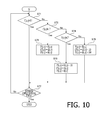
- FIG. 10 is a flowchart illustrating a sequence of an overlay process.
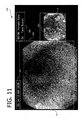
- FIG. 11 is an example of a display screen generated by a screen display process.
- FIG. 1 is a block diagram illustrating a general configuration of an electronic endoscope device 1 according to the embodiment of the invention.
- the electronic endoscope device 1 according to the embodiment includes an electronic scope 100 , a processor 200 for an electronic endoscope, a monitor 300 and a printer 400 .
- the processor 200 for an electronic endoscope includes a system controller 202 and a timing controller 206 .
- the system controller 202 executes various programs stored in a memory 204 and totally controls the entire electronic endoscope device 1 . Further, the system controller 202 changes various settings of the electronic endoscope device 1 in accordance with an instruction from a user (an operator or an assistant) input to an operation panel 208 .
- the timing controller 206 outputs clock pulses for adjusting operation timings of each part to various circuits in the electronic endoscope device 1 .
- the processor 200 for an electronic endoscope includes a light source 230 which supplies illumination light being a white light beam to an LCB (Light Carrying Bundle) 102 of the electronic scope 100 .
- the light source 230 includes a lamp 232 , a lamp power supply 234 , a condenser lens 236 and a dimmer control device 240 .
- the lamp 232 is a high luminance lamp which emits illumination light while being supplied drive power from the lamp power supply 234 , and, for example, a Xenon lamp, a metal-halide lamp, a mercury lamp or a halogen lamp is used.
- the illumination light emitted by the lamp 232 is converged by the condenser lens 236 , and is guided to the LCB 102 via the dimmer control device 240 .
- the dimmer control device 240 is a device which adjusts the light amount of the illumination light guided to the LCB 102 based on control by the system controller 202 , and includes an aperture stop 242 , a motor 243 and a driver 244 .
- the driver 244 generates a driving current for driving the motor 243 , and supplies the driving current to the motor 243 .
- the aperture stop 242 is driven by the motor 243 , and changes the aperture through which the illumination light proceeds, and thereby controls the light amount of the illumination light passing through the aperture.
- the illumination light guided to the LCB 102 from an entrance face propagates through the inside of the LCB 102 , is emitted from an exit face of the LCB 102 disposed at a tip part of the electronic scope 100 , and illuminates a subject via a light distribution lens 104 .
- Light reflected from the subject forms an optical image on a light-receiving surface of a solid state image pickup device 108 via an objective lens 106 .
- the solid state image pickup device 108 is, for example, a single-chip color CCD (Charge Coupled Device) image sensor having various filters, such as, an IR (Infra Red) cut filer 108 a and a bayer array color filter 108 b , disposed on the light-receiving surface thereof, and generates an image-capturing signal of each of three primary colors responsive to the optical image converged on the light receiving surface.
- the generated image-capturing signal is amplified by a driver signal processing circuit 112 provided in a connection part of the electronic scope 100 , and then is converted into an image signal composed of a luminance signal Y and color difference signals Cb and Cr.
- the image signal converted into the luminance signal Y and the color difference signals Cb and Cr is further converted into a digital signal and then is transmitted to an image processing unit 220 of the processor 200 for an electronic endoscope.
- the driver signal processing circuit 112 reads out unique information unique to the electronic scope 100 by accessing the memory 114 .
- the unique information of the electronic scope 100 recorded in the memory 114 includes, for example, the number of pixels and the sensitivity of the solid state image pickup device 108 , operable frame rates and the like.
- the driver signal processing circuit 112 outputs the unique information read from the memory 114 to the system controller 202 .
- the system controller 202 executes various calculations based on the unique information of the electronic scope 100 , and generates a control signal. Using the generated control signal, the system controller 202 controls the operations and timings of the various circuits in the processor 200 for an electronic endoscope so that processes suitable for the electronic scope 100 connected to the processor 200 for an electronic endoscope are executed.
- the timing controller 206 supplies clock pulses to the driver signal processing circuit 112 and the image processing unit 220 in accordance with timing control by the system controller 202 .
- the driver signal processing circuit 112 drives and controls the solid state image pickup device 108 at timings in synchronization with a frame rate of video processed by the processor 200 for an electronic endoscope side, in accordance with the clock pulses supplied from the timing controller 206 .
- the image processing unit 220 of the processor 200 for an electronic endoscope generates a video signal for monitor representation of an endoscopic image or the like based on the image signal transmitted from the driver signal processing circuit 112 of the electronic scope 100 , under control of the system controller 202 , and outputs the video signal to the monitor 300 .
- the operator observes or treats, for example, an inside of a digestive tube, while checking the endoscopic image displayed on the monitor 300 .
- the processor 200 for an electronic endoscope is connected to a server 600 via a NIC (Network Interface Card) 210 and a network 500 .
- the processor 200 for an electronic endoscope obtains, from the server 600 , information concerning endoscopic examination (e.g., electronic medical record of a patient or information on an operator) and displays the information on the monitor 300 or the operation panel 208 . Further, the processor 200 for an electronic endoscope transmits endoscopic examination results (endoscopic image data, examination conditions, image analysis results which are described later, an operator's opinion or the like) to the server 600 to cause the server 600 to store the endoscopic examination results.
- endoscopic examination results endoscopic image data, examination conditions, image analysis results which are described later, an operator's opinion or the like
- the electronic endoscope device 1 includes the function of recording still images of a plurality of endoscopic images in association with information on captured portions (i.e., positions (insertion lengths) of the tip part of the electronic scope 100 at the time of image capturing).
- captured portions i.e., positions (insertion lengths) of the tip part of the electronic scope 100 at the time of image capturing.
- a plurality of optical sensors 132 are provided at constant intervals (e.g., intervals of 5 centimeters) in the length direction.
- the optical sensor 132 is a light-receiving device, such as a photodiode, and detects external light (room lighting of a room in which the endoscopic examination is being performed).
- the optical sensors 130 provided on a part of the insertion unit 130 inserted into the digestive tube do not detect the external light, and the optical sensors 132 provided on a part of the insertion unit 130 not inserted into the digestive tube detect the external light. Therefore, by judging that the length of distribution of the optical sensors not detecting the light is the length of the insertion unit 130 inserted into the inside of the digestive tube, it becomes possible to obtain information concerning the position of the tip part of the electronic scope 100 (the insertion length).
- the optical sensors 132 are connected to the driver signal processing circuit 112 , and transmit sensor signals indicating the amounts of the detected light to the driver signal processing circuit 112 .
- the driver signal processing circuit 112 calculates the position (the insertion length) Pos of the tip part of the electronic scope 100 based on the sensor signals from the optical sensors 132 .
- an operation signal is transmitted from the operation unit 120 to the driver signal processing circuit 112 .
- the system controller 202 obtains the operation signal for obtaining a still image from the operation unit 120
- the system controller 202 transmits an instruction for obtaining a still image to the image processing unit 220 together with the current position information (the insertion length) Pos of the tip part of the electronic scope 100 .
- the image processing unit 220 a still image of an endoscopic observation image is recorded while being associated with the position information Pos of the electronic scope 100 at the time of image capturing. Details about a process in which the image processing unit 220 records a still image are described later.
- FIG. 2 is a lock diagram illustrating a general configuration of the image processing unit 220 .
- the image processing unit 220 includes a first image processing circuit 222 , an image memory 224 , a memory 226 and a second image processing circuit 228 .
- the first image processing circuit 222 executes various types of image processing for the image signal from the driver signal processing circuit 112 , and outputs the signal to the image memory 224 .
- the first image processing circuit 222 includes an RGB conversion unit 222 a , a TE processing unit 222 b , an effective pixel judgment unit 222 c , a color space conversion unit 222 d , a lesion judgment unit (a threshold processing unit) 222 e and an overlay processing unit 222 f .
- the second image processing circuit 228 includes a display screen generating unit 228 a . Concrete processes executed by each of the units of the first image processing circuit 222 and the second image processing circuit 228 are explained later.
- FIG. 3 illustrates a general configuration of a memory area provided in the image memory 224 .
- the image memory 224 is able to store a maximum of seven sets of the normal observation image data N, the tone enhanced image data E and the overlay image data S.
- the image memory 224 is configured to store the image data output by the first image processing circuit 222 (the normal observation image data N, the tone enhanced image data E or the overlay image data S) in one of the memory area groups P 0 to P 6 in accordance with control of the system controller 202 . It should be noted that the memory area P 0 is overwritten with the image data sequentially output from the first image processing circuit 222 , so that the image data constituting a real time video image is held thereon.
- the image data output from the first image processing circuit 222 is written only when an instruction is inputted from the system controller 202 . That is, the image memory 224 is able to record a maximum of six still images.
- FIG. 4 illustrates a general configuration of a memory area provided in the memory 226 .
- the memory 226 includes an RGB matrix memory area 226 a , a flag memory area 226 b , and a setting information memory area 226 c .
- a RGB matrix memory area 226 a an RGB conversion matrix coefficient M used in an RGB conversion process S 1 which is described later is stored.
- a flag table F used for a process in the first image processing circuit 222 is stored.
- the flag table F is a numeric value table constituted by a flag f(x, y) indicating an analysis result concerning each pixel (x, y) constituting the image data.
- the setting information memory area 226 c various types of settings used for a process in the image processing unit 220 are stored.
- the memory area group Pk is associated with the position information (the insertion length) Pos of the tip part of the electronic scope 100 .
- the memory area group P 1 corresponds to a range of the insertion length Pos of a deepest portion (e.g., a portion near a right colic flexure of a transverse colon) in an examination area, and the insertion length Pos becomes shorter as the value of k increases.
- the memory area group Pk in which the image data is recorded is determined depending on the position information Pos (the position of the tip part of the electronic scope 100 at the time of image capturing) of the image data.
- the second image processing circuit 228 generates the video signal for monitor representation using the image signal stored in the image memory 224 , and outputs the video signal to the monitor 300 .
- FIG. 5 is a flowchart illustrating the sequence of the process executed by the image processing unit 220 .
- the RGB conversion process S 1 is executed by the RGB conversion circuit 222 a of the first image processing circuit 222 .
- the RGB conversion unit 222 a amplifies respectively the luminance signal Y and color difference signals Cb and Cr transmitted from the driver signal processing circuit 112 , and then converts the signals to the three primary color signals R, G, B.
- the RGB conversion process S 1 is executed using the RGB conversion matrix coefficient M stored in the RGB matrix memory area 226 a .
- the RGB conversion matrix coefficient M has been set in advance in accordance with the spectral property of the illumination light used for image capturing, and correction of the spectral property of the illumination light is executed concurrently with the conversion in a signal format from the Y, Cr, Cb signals to the R, G, B signals. Further, when the RGB conversion process S 1 is finished, the three primary color signals R, G, B of the generated normal observation image data N are output to the image memory 224 , and are stored respectively in the normal image memory areas 0 n R, 0 n G, 0 n B.
- the image analysis mode is an operation mode in which color information (in particular, hue and saturation) is analyzed for each pixel of the image data, and whether it is a pixel of a lesion portion is judged based on a predetermined judgment criteria from an analysis result of the color information, and the pixel of the lesion portion is displayed in a discriminating manner.
- the type of lesion to be judged can be selected depending on content of the examination.
- pixels in color regions respectively specific to observation images of an ulcer (a white lesion including a white moss or mucous) which is a lesion of inflammatory bowel disease (IBD) and inflammation (a red coloration lesion including an edema or hemorrhagic) are extracted, and are displayed in a discriminating manner.
- IBD inflammatory bowel disease
- inflammation a red coloration lesion including an edema or hemorrhagic
- the electronic endoscope device 1 is configured to operate in two operation modes including the image analysis mode and the normal observation mode.
- the operation mode is changed by a user operation to the operation unit 120 of the electronic scope 100 or the operation panel 208 of the processor 200 for an electronic endoscope.
- the operation mode is set to the normal observation mode (S 2 : No)
- the process proceeds to S 9 .
- the TE process S 3 is a process in which, in order to enhance the judgment accuracy of lesion, the gain adjustment for giving a non-linear gain to each of the primary color signals R, G, B is executed, and the dynamic range around a color region (in particular, a boundary portion) specific to the lesion to be judged is substantially widened, and the effective resolution for color representation is enhanced.
- the TE process S 3 a process where a monotonically increasing non-linear gain as shown in FIG.
- the tone enhanced image data E is executed.
- a boundary region R A denotes mapping of a boundary of a color region specific to an ulcer to R space
- a boundary region R B denotes mapping of a boundary of a color region specific to inflammation to R space
- the inclination of a gain curve becomes most steep around the boundary regions R A and R B .
- different gain adjustments may be executed for the primary color signals R, G, B, respectively. Furthermore, a process in which the same non-liner gain is given to the primary color signals G, B and a different non-linear gain is given to the primary color signal R may be performed. Further, the three primary signals R′, G′, B′ (the tone enhanced image data E) generated by the TE process S 3 are output to the image memory 224 , and are stored in the tone enhanced image memory areas 0 e R, 0 e G 0 e B, respectively.
- an inflammation portion changes in color to red
- an ulcer portion changes in color to white
- a normal portion changes in color to green. Therefore, when the tone enhanced image data E generated by the TE process S 3 is displayed on the monitor 300 , it becomes possible to visually recognize a lesion portion (an inflammation portion or an ulcer portion) easily relative to the normal observation image data N.
- FIG. 7 is a flowchart illustrating the sequence of the effective pixel judgment process S 4 .
- the effective pixel judgment process S 4 shown in FIG. 7 is executed sequentially for all the pixels (x, y) constituting the image data.
- first a correction intensity int(x, y) is calculated according to the following expression 1 from the primary color signals R′(x, y), G′(x, y), B′(x, y), for each pixel (x, y) (S 41 ).
- int( x,y ) 0.3* R ′( x,y )+0.59* G ′( x,y )+0.11* B ′( x,y ) (Expression 1)
- the value of the calculated correction intensity (x, y) is used for a suitable exposure judgment S 42 . Further, as can be seen from the expression 1, the correction intensity int(x, y) is not obtained as a simple average of the primary color signals R′(x, y), G′(x, y), B′(x, y), but is obtained as a weighted average based on a relative luminous efficiency property of a human (an operator).
- the suitability of exposure (whether or not it is an exposure level required for image analysis) is judged based on the correction intensity int(x, y) and the primary color signals R′(x, y), G′(x, y), B′(x, y) of the tone enhanced image data E calculated in the process S 41 (S 42 ).
- the suitable exposure judgment process S 42 it is judged to be a suitable exposure (S 42 : Yes) when at least one of the following two conditions (the expression 2 and the expression 3) is satisfied.
- the upper limit of the correction intensity int(x, y) is defined by the expression 2, and the lower limit of each of the primary color signals R′(x, y), G′(x, y), B′(x, y) is defined by the expression 3. int( x,y ) ⁇ 235 (Expression 2) Max ⁇ R ′( x,y ) G ′( x,y ), B ′( x,y ) ⁇ >20 (Expression 3)
- the effective pixel judgment unit 222 c changes the value of the flag (x, y) corresponding to the pixel (x, y) of the flag table F stored in the flag memory area 226 b of the memory 226 to “1” (S 43 ).
- the flag f (x, y) takes a value of one of 0 to 3. The following is the definition of each of the flag values.
- the effective pixel judgment unit 222 c changes the value of the flag f(x, y) of the flag table F to “0” (S 44 ).
- the color space conversion process S 5 is a process where the tone enhanced image data in the RGB space defined by the RGB three primary colors is converted into image data in HSI (Hue-Saturation-Intensity) space defined by three elements of Hue, Saturation and Intensity. Specifically, in the color space conversion process S 5 , the primary color signals R′(x, y), G′(x, y), B′(x, y) of each pixel (x, y) of the tone enhanced image data E are converted into hue H(x, y), saturation S(x, y), intensity I(x, y).
- HSI Human-Saturation-Intensity
- the color space conversion process S 5 is executed only for the pixels (x, y) for which the value of the flag f (x, y) is set to “1” (i.e., the pixel (x, y) judged to be suitable exposure in the above described effective pixel judgment process S 4 ).
- the lesion judgment process S 6 is a process where, for each pixel (x, y) of the endoscopic image, a predicted state (normal, inflammation, ulcer) of a portion corresponding to the pixel is judged depending on which of regions I to III of FIG. 9 described later the pixel (x, y) is plotted in.
- FIG. 8 is a flowchart illustrating the sequence of the lesion judgment process S 6 .
- the lesion judgment process S 6 shown in FIG. 8 is executed sequentially for all the pixels (x, y) constituting the image data.
- the lesion judgment process S 6 first it is judged whether or not data of each pixel (x, y) is effective with reference to the flag table F (S 61 ).
- the value of the flag table f(x, y) is “1” (image data effective)
- an inflammation judgment process S 62 is executed.
- the value of the flag f (x, y) is “0” (image data invalid)
- the process proceeds to the process S 66 without executing the inflammation judgment process S 62 .
- FIG. 9 is a scatter diagram where the image data (a pair of data composed of hue H(x, y) and saturation S(x, y)) of living tissue images extracted from the endoscope image data of a plurality of inflammatory bowel disease patients are plotted.
- the scatter diagram of FIG. 9 is divided into a region III which is surrounded by a dashed line on the left side, a region II which is surrounded by a chain line on the lower right side and a region I of the other region.
- each pixel value (H(x, y), S(x, y)) is plotted in the region II of FIG. 9 . Specifically when the pixel value (H(x, y), S(x, y)) satisfies the following expression 4 and the expression 5, it is judged that the pixel value is plotted in the region II (i.e., it is a pixel of an inflammation portion).
- ⁇ H1 , ⁇ S1 , and ⁇ S2 are correction values which can be set by the operator, and, through setting of these correction values, the severity (sensitivity) of the judgment can be adjusted appropriately. 130+ ⁇ H1 ⁇ H ( x,y ) (Expression 4) 60+ ⁇ S1 ⁇ S ( x,y ) ⁇ 100+ ⁇ S2 (Expression 5)
- the ulcer judgment process S 64 it is judged whether or not the pixel value (H(x, y), S(x, y)) is plotted in the region III of FIG. 9 . Specifically, when H(x, y) and S(x, y) satisfy the following expression 6 or the expressions 7 and 8, the pixel value (H(x, y), S(x, y)) is judged to be plotted in the region III (i.e., it is a pixel of an ulcer portion).
- ⁇ S3 , ⁇ S4 , and ⁇ H3 are correction values which can be set by the operator, and, through setting of these correction values, the severity (sensitivity) of the judgment can be adjusted appropriately.
- the overlay process S 7 is a process where, for the pixel judged to be a lesion portion such as inflammation or an ulcer by the lesion judgment process S 6 , the color is changed to have a color tone associated with the lesion (the flag value) so that the pixel can be distinguished from an pixel judged to be normal (not having a lesion).
- a process where red color is enhanced (specifically, a red component is increased) for the pixel judged to be an ulcer and yellow color is enhanced (specifically, green and blue components are enhanced) for a pixel judged to be inflammation is executed.
- FIG. 10 is a flowchart illustrating a sequence of the overlay process S 7 .
- the overlay process S 7 shown in FIG. 10 is executed sequentially for all the pixels (x, y) constituting the normal observation image data N.
- the overlay process S 7 first the value of the flag f(x, y) corresponding each pixel (x, y) is judged with reference to the flag table F (S 71 , S 72 , S 74 ).
- the value of the flag is “0” (image data invalid) (S 71 : Yes)
- the process proceeds directly to the process S 77 .
- the primary color signals R(x, y), G(x, y), B(x, y) of the normal observation image data N are defined as the primary color signals R′′(x, y), G′′(x, y), B′′(x, y) of the overlay image data S without change (S 73 ), and the process proceeds to the process S 77 .
- a value obtained by adding 100 to the primary color signals G(x, y) and B(x, y) of the normal observation image data N are defined as the values of the G′′(x, y) and B′′(x, y) of the overlay image data S, and the primary color signal R(x, y) of the normal observation image data N is defined as the primary color signal R′′(x, y) of the overlay image data S without change (S 76 ), and the process proceeds to the process S 77 .
- primary color signals R, G, B of the normal observation image data N are used for the overlay process S 7
- primary color signals R′(x, y), G′(x, y), B′(x, y) of the tone enhanced image data E may be used.
- a judgment S 8 ( FIG. 5 ) on whether or not an instruction for storing a still image is issued is executed.
- the image processing unit 220 receives the position information Pos of the tip part of the electronic scope 100 together with the instruction for storing a still image from the driver signal processing circuit 112 (S 8 : Yes)
- the image processing unit 220 stores copies of the normal observation image data N, the tone enhanced image data E and the overlay image data S stored in the memory area groups P 0 of the image memory 224 in one of the memory area groups P 1 to P 6 corresponding to the position information Pos (S 9 ).
- the screen display process S 10 is executed.
- the process proceeds to the screen display process S 10 without executing the process S 9 .
- the next screen display process S 10 is a process where the display screen data for displaying on the monitor 300 is generated and is converted into a video signal and is output, and is executed by the display screen generating unit 228 a of the second image processing circuit 228 .
- the display screen generating unit 228 a is able to generate a plurality of types of display screen data in accordance with control by the system controller 202 .
- FIG. 11 is an example of a display screen generated by the screen display process S 10 , and is an analysis mode observation screen 320 displayed during endoscopic observation in the image analysis mode.
- the analysis mode observation screen 320 includes a date and time display area 321 on which date and time of image capturing is displayed, a basic information display area 322 on which basic information concerning diagnosis (e.g., a medical record number, a patient name and an operator name) is displayed, a normal image display area 324 on which the normal observation image data N (or the tone enhanced image data E) is displayed, and an analysis image display area 325 on which the overlay image data S (the observation image after the overlay process S 7 ) is displayed.
- a date and time display area 321 on which date and time of image capturing is displayed
- a basic information display area 322 on which basic information concerning diagnosis (e.g., a medical record number, a patient name and an operator name) is displayed
- a normal image display area 324 on which the normal observation image data N (or the tone enhanced image data
- the display screen generating unit 228 a reads the real time normal observation image data N and the overlay image data S from the memory area group P 0 of the image memory 224 , and displays them on the normal image display area 324 and the analysis image display area 325 , respectively. Furthermore, on the date and time display area 321 and the basic information display area 322 , information provided by the system controller 202 is displayed.
- the operator conducts the endoscopic observation while viewing the analysis mode observation screen 320 . Specifically, the operator conducts the endoscopic observation while viewing the normal observation image data N (or the tone enhanced image data E) displayed on the normal image display area 324 and while referring to the overlay image data S displayed on the analysis image display area 325 .
- the operator conducts the endoscopic observation while viewing the normal observation image data N (or the tone enhanced image data E) displayed on the normal image display area 324 and while referring to the overlay image data S displayed on the analysis image display area 325 .
- judgment on a lesion is made in the HSI space
- judgment on a lesion may be made in the HSV (HSB) space based on Hue, Saturation and Value (or Brightness) in place of HSI space.
- HSV HSV
- the TE process S 3 is executed in the RGB space; however, the TE process S 3 may be executed in the HSI space after the color space conversion process S 5 .
- the configuration where the information on the position of the tip part of the electronic scope 100 (the image capturing position) is obtained using the optical sensor 132 is not limited to such a configuration, and a configuration where the information on the image capturing position is obtained by another means may be employed.
- a configuration where an optical proximity sensor having a light source and a light-receiving element are provided in the insertion unit 130 of the electronic scope 100 in place of the optical sensor 132 may be employed. In this case, when the optical proximity sensor is inserted in to a digestive tube, light reflected from the inner wall of the digestive tube is detected by the light-receiving element, and proximity is detected.
- the distribution length of the optical proximity-sensors whose light-receiving elements are receiving light is the length of the insertion unit 130 being inserted into the digestive tube, the information on the position of the tip part of the electronic scope 100 can be obtained.
- a configuration where a moving amount sensor which detects the moving amount (the distance and the direction of movement) by the same principle as that of an optical mouse is provided in the insertion unit 130 of the electronic scope 100 in place of the optical sensor 132 may be employed. In this case, only one moving amount sensor may be provided close to the tip of the insertion unit 130 .
- a light source of the optical proximity-sensor or the moving amount sensor a light source (LD or LED) of a wavelength within near infrared to a visible light region may be used, however, by using a light source of a red light region having a high degree of reflectivity on a living tissue surface, a high degree of detection accuracy can be obtained.
- the position of the tip part of the electronic endoscope may be determined from these images. Furthermore, by calculating the moving amount of the tip part of the endoscope in a digestive tract through image analysis of an endoscopic image, the position of the tip part of the endoscope may be determined.
- the driver signal processing circuit 112 automatically issues an instruction for storing a still image and automatically storing a still image when the tip part of the insertion unit 130 reaches a predetermined still image obtaining position (an observation point) while the insertion unit 130 of the electronic scope 100 is pulled out from the deepest portion of an examination area.
- a CCD image sensor is used as the solid state image pickup device 108 ; however, a configuration where a solid state image pickup device having a different configuration, such as a CMOS (Complementary Metal Oxide Semiconductor), is used may be employed.
- CMOS Complementary Metal Oxide Semiconductor
- the solid state image pickup device 108 having the RGB bayer array color filter 108 b is used; however, a configuration having a solid state image pickup device having a complementary color filter of Cy (Cyan), Mg (Magenta), Ye (Yellow) and G (Green) may be employed.
Abstract
Description
int(x,y)=0.3*R′(x,y)+0.59*G′(x,y)+0.11*B′(x,y) (Expression 1)
int(x,y)<235 (Expression 2)
Max{R′(x,y)G′(x,y),B′(x,y)}>20 (Expression 3)
130+δH1 ≦H(x,y) (Expression 4)
60+δS1 ≦S(x,y)≦100+δS2 (Expression 5)
S(x,y)≦65+δS3 (Expression 6)
S(x,y)≦85+δS4 (Expression 7)
120+δH2 ≦H(x,y)≦200+δH3 (Expression 8)
Claims (14)
Applications Claiming Priority (3)
| Application Number | Priority Date | Filing Date | Title |
|---|---|---|---|
| JP2012158248A JP6067264B2 (en) | 2012-07-17 | 2012-07-17 | Image processing apparatus and endoscope apparatus |
| JP2012-158248 | 2012-07-17 | ||
| PCT/JP2013/063385 WO2014013778A1 (en) | 2012-07-17 | 2013-05-14 | Image processing device and endoscopic instrument |
Publications (2)
| Publication Number | Publication Date |
|---|---|
| US20150193929A1 US20150193929A1 (en) | 2015-07-09 |
| US9430833B2 true US9430833B2 (en) | 2016-08-30 |
Family
ID=49948615
Family Applications (1)
| Application Number | Title | Priority Date | Filing Date |
|---|---|---|---|
| US14/413,905 Active US9430833B2 (en) | 2012-07-17 | 2013-05-14 | Image processing device and endoscope device |
Country Status (5)
| Country | Link |
|---|---|
| US (1) | US9430833B2 (en) |
| EP (1) | EP2875776B1 (en) |
| JP (1) | JP6067264B2 (en) |
| CN (1) | CN104470416B (en) |
| WO (1) | WO2014013778A1 (en) |
Cited By (8)
| Publication number | Priority date | Publication date | Assignee | Title |
|---|---|---|---|---|
| US20170273543A1 (en) * | 2015-08-13 | 2017-09-28 | Hoya Corporation | Evaluation value calculation device and electronic endoscope system |
| US20170280971A1 (en) * | 2015-08-13 | 2017-10-05 | Hoya Corporation | Evaluation value calculation device and electronic endoscope system |
| US10231600B2 (en) | 2015-02-23 | 2019-03-19 | Hoya Corporation | Image processing apparatus |
| US10521901B2 (en) | 2015-02-27 | 2019-12-31 | Hoya Corporation | Image processing apparatus |
| CN111325709A (en) * | 2019-12-26 | 2020-06-23 | 联博智能科技有限公司 | Wireless capsule endoscope image detection system and detection method |
| JPWO2019216084A1 (en) * | 2018-05-09 | 2021-06-10 | 富士フイルム株式会社 | Inspection video processing device, inspection video processing method and inspection video processing program |
| US20210345857A1 (en) * | 2017-06-19 | 2021-11-11 | Ambu A/S | Method for processing image data using a non-linear scaling model and a medical visual aid system |
| US11328415B2 (en) * | 2017-06-15 | 2022-05-10 | Fujifilm Corporation | Medical image processing device, endoscope system, and method of operating medical image processing device |
Families Citing this family (25)
| Publication number | Priority date | Publication date | Assignee | Title |
|---|---|---|---|---|
| JP6097629B2 (en) | 2013-04-26 | 2017-03-15 | Hoya株式会社 | Lesion evaluation information generator |
| US10231670B2 (en) * | 2014-06-19 | 2019-03-19 | Masimo Corporation | Proximity sensor in pulse oximeter |
| JP2016158682A (en) * | 2015-02-27 | 2016-09-05 | Hoya株式会社 | Image processing device |
| WO2016189622A1 (en) * | 2015-05-25 | 2016-12-01 | オリンパス株式会社 | Image processing device, medical observation system, and image processing program |
| US10702127B2 (en) | 2015-06-25 | 2020-07-07 | Hoya Corporation | Endoscope system and evaluation value calculation device |
| JP6461739B2 (en) * | 2015-07-28 | 2019-01-30 | 富士フイルム株式会社 | Image processing apparatus, endoscope system, and method of operating image processing apparatus |
| US10918270B2 (en) | 2015-09-30 | 2021-02-16 | Hoya Corporation | Endoscope system and evaluation value calculation device |
| US10512433B2 (en) | 2016-03-03 | 2019-12-24 | Hoya Corporation | Correction data generation method and correction data generation apparatus |
| CN109068945B (en) | 2016-03-29 | 2020-12-01 | 富士胶片株式会社 | Image processing apparatus, method of operating image processing apparatus, and recording medium |
| US10646102B2 (en) * | 2016-08-31 | 2020-05-12 | Hoya Corporation | Processor for electronic endoscope, and electronic endoscope system |
| WO2018066318A1 (en) * | 2016-10-05 | 2018-04-12 | 富士フイルム株式会社 | Processor device, endoscope system, and method for operating processor device |
| JPWO2018070474A1 (en) * | 2016-10-14 | 2019-06-24 | Hoya株式会社 | Endoscope system |
| DE112018000393T5 (en) * | 2017-01-16 | 2019-09-26 | Hoya Corporation | Endoscope system and image display device |
| WO2019195146A1 (en) | 2018-04-03 | 2019-10-10 | Boston Scientific Scimed, Inc. | Systems and methods for diagnosing and/or monitoring disease |
| CN112312822A (en) * | 2018-07-06 | 2021-02-02 | 奥林巴斯株式会社 | Image processing device for endoscope, image processing method for endoscope, and image processing program for endoscope |
| WO2020012872A1 (en) * | 2018-07-09 | 2020-01-16 | 富士フイルム株式会社 | Medical image processing device, medical image processing system, medical image processing method, and program |
| CN109523507B (en) * | 2018-09-26 | 2023-09-19 | 苏州六莲科技有限公司 | Method and device for generating lesion image and computer readable storage medium |
| WO2020084651A1 (en) * | 2018-10-22 | 2020-04-30 | オリンパス株式会社 | Image processing device, image processing method, endoscope system, and endoscopic observation method |
| JP7256046B2 (en) * | 2019-03-22 | 2023-04-11 | ソニー・オリンパスメディカルソリューションズ株式会社 | Medical image processing device, medical observation device, operating method of medical image processing device, and medical image processing program |
| CN109949301B (en) * | 2019-03-26 | 2021-05-18 | 合肥工业大学 | Wireless endoscope camera shooting illumination system |
| CN110400308B (en) * | 2019-07-30 | 2022-01-28 | 青岛海信医疗设备股份有限公司 | Image display method, device, equipment and storage medium |
| CN110533659A (en) * | 2019-09-03 | 2019-12-03 | 安翰科技(武汉)股份有限公司 | Alimentary canal image decision method and alimentary canal clean-up performance judgment method and its computer equipment and readable storage medium storing program for executing including it |
| CN113129356B (en) * | 2020-01-16 | 2022-08-23 | 安翰科技(武汉)股份有限公司 | Capsule endoscope system, image staining area recognition method thereof, and storage medium |
| KR20220164755A (en) * | 2020-04-06 | 2022-12-13 | 고쿠리츠다이가쿠호진 니이가타 다이가쿠 | Data generating device, data generating method and program |
| CN113920042B (en) * | 2021-09-24 | 2023-04-18 | 深圳市资福医疗技术有限公司 | Image processing system and capsule endoscope |
Citations (30)
| Publication number | Priority date | Publication date | Assignee | Title |
|---|---|---|---|---|
| JPH02114931A (en) | 1988-10-26 | 1990-04-27 | Toshiba Corp | Image processor of electronic endoscope |
| JPH034832A (en) | 1989-06-01 | 1991-01-10 | Toshiba Corp | Electronic endoscope device |
| JP2002172082A (en) | 2000-06-06 | 2002-06-18 | Fuji Photo Film Co Ltd | Method and device for fluorescent image display |
| US20020105505A1 (en) | 2000-06-06 | 2002-08-08 | Fuji Photo Film Co., Ltd. | Fluorescent-light image display method and apparatus therefor |
| US20020177779A1 (en) | 2001-03-14 | 2002-11-28 | Doron Adler | Method and system for detecting colorimetric abnormalities in vivo |
| JP2004154176A (en) | 2002-11-01 | 2004-06-03 | Olympus Corp | Endoscope image pickup device |
| US20040155957A1 (en) | 2003-02-07 | 2004-08-12 | Pentax Corporation | Video endoscope apparatus |
| US20060087557A1 (en) | 2004-10-20 | 2006-04-27 | Fuji Photo Film Co., Ltd. | Electronic endoscope apparatus |
| JP2006142002A (en) | 2004-10-20 | 2006-06-08 | Fuji Photo Film Co Ltd | Electronic endoscope apparatus |
| US20070161858A1 (en) | 2002-01-11 | 2007-07-12 | Olympus Corporation | Endoscope image pick-up apparatus |
| EP1839558A1 (en) | 2005-01-19 | 2007-10-03 | Olympus Corporation | Electronic endoscope |
| EP1994878A1 (en) | 2006-03-16 | 2008-11-26 | Olympus Medical Systems Corp. | Image processing device for medical use and image processing method for medical use |
| WO2008146447A1 (en) | 2007-05-29 | 2008-12-04 | Olympus Medical Systems Corp. | Capsule endoscope display device |
| JP2009106424A (en) | 2007-10-29 | 2009-05-21 | Hoya Corp | Electronic endoscope signal-processing device and electronic endoscope system |
| EP2096859A2 (en) | 2008-02-26 | 2009-09-02 | Given Imaging Ltd. | Method for enhancing in-vivo image contrast |
| US20090309961A1 (en) | 2008-06-16 | 2009-12-17 | Olympus Corporation | Image processing apparatus, image processing method and image processing program |
| US20100007724A1 (en) | 2008-07-08 | 2010-01-14 | Hoya Corporation | Electronic endoscope signal-processing device and electronic endoscope system |
| JP2010115243A (en) | 2008-11-11 | 2010-05-27 | Hoya Corp | Image signal processing apparatus for electronic endoscope |
| US20100158330A1 (en) * | 2005-09-12 | 2010-06-24 | Dvp Technologies Ltd. | Medical Image Processing |
| JP2010172673A (en) | 2009-02-02 | 2010-08-12 | Fujifilm Corp | Endoscope system, processor for endoscope, and endoscopy aiding method |
| CN101803899A (en) | 2009-02-16 | 2010-08-18 | 奥林巴斯株式会社 | Image processing apparatus and image processing method |
| US20110075901A1 (en) | 2009-09-30 | 2011-03-31 | Fujifilm Corporation | Medical image processing apparatus and method and computer-readable recording medium |
| US20110176730A1 (en) | 2010-01-15 | 2011-07-21 | Olympus Corporation | Image processing device, endoscope system, program, and image processing method |
| WO2011096279A1 (en) | 2010-02-05 | 2011-08-11 | オリンパス株式会社 | Image processing device, endoscope system, program and image processing method |
| JP2011182993A (en) | 2010-03-09 | 2011-09-22 | Panasonic Electric Works Co Ltd | Dental plaque detector |
| US20110242301A1 (en) | 2010-03-30 | 2011-10-06 | Olympus Corporation | Image processing device, image processing method, and program |
| JP2011218090A (en) | 2010-04-14 | 2011-11-04 | Olympus Corp | Image processor, endoscope system, and program |
| CN102243762A (en) | 2010-05-11 | 2011-11-16 | 奥林巴斯株式会社 | Image processing apparatus and image processing method |
| JP2011255006A (en) | 2010-06-09 | 2011-12-22 | Olympus Corp | Image processor, endoscopic device, program and image processing method |
| US20140320620A1 (en) * | 2013-04-26 | 2014-10-30 | Kyoto University | Lesion evaluation information generator, and method and computer readable medium therefor |
-
2012
- 2012-07-17 JP JP2012158248A patent/JP6067264B2/en active Active
-
2013
- 2013-05-14 WO PCT/JP2013/063385 patent/WO2014013778A1/en active Application Filing
- 2013-05-14 US US14/413,905 patent/US9430833B2/en active Active
- 2013-05-14 EP EP13819790.0A patent/EP2875776B1/en active Active
- 2013-05-14 CN CN201380037982.5A patent/CN104470416B/en active Active
Patent Citations (52)
| Publication number | Priority date | Publication date | Assignee | Title |
|---|---|---|---|---|
| JPH02114931A (en) | 1988-10-26 | 1990-04-27 | Toshiba Corp | Image processor of electronic endoscope |
| JPH034832A (en) | 1989-06-01 | 1991-01-10 | Toshiba Corp | Electronic endoscope device |
| US7283858B2 (en) * | 2000-06-06 | 2007-10-16 | Fujifilm Corporation | Fluorescent-light image display method and apparatus therefor |
| JP2002172082A (en) | 2000-06-06 | 2002-06-18 | Fuji Photo Film Co Ltd | Method and device for fluorescent image display |
| US20020105505A1 (en) | 2000-06-06 | 2002-08-08 | Fuji Photo Film Co., Ltd. | Fluorescent-light image display method and apparatus therefor |
| US20020177779A1 (en) | 2001-03-14 | 2002-11-28 | Doron Adler | Method and system for detecting colorimetric abnormalities in vivo |
| US20070161858A1 (en) | 2002-01-11 | 2007-07-12 | Olympus Corporation | Endoscope image pick-up apparatus |
| JP2004154176A (en) | 2002-11-01 | 2004-06-03 | Olympus Corp | Endoscope image pickup device |
| US7938771B2 (en) | 2002-11-01 | 2011-05-10 | Olympus Corporation | Endoscope image pick-up apparatus |
| US20040155957A1 (en) | 2003-02-07 | 2004-08-12 | Pentax Corporation | Video endoscope apparatus |
| JP2004236952A (en) | 2003-02-07 | 2004-08-26 | Pentax Corp | Electronic endoscope apparatus |
| US7289140B2 (en) | 2003-02-07 | 2007-10-30 | Pentax Corporation | Video endoscope apparatus |
| US20060087557A1 (en) | 2004-10-20 | 2006-04-27 | Fuji Photo Film Co., Ltd. | Electronic endoscope apparatus |
| JP2006142002A (en) | 2004-10-20 | 2006-06-08 | Fuji Photo Film Co Ltd | Electronic endoscope apparatus |
| US8675058B2 (en) * | 2004-10-20 | 2014-03-18 | Fujinon Corporation | Electronic endoscope apparatus |
| EP1839558A1 (en) | 2005-01-19 | 2007-10-03 | Olympus Corporation | Electronic endoscope |
| US20100158330A1 (en) * | 2005-09-12 | 2010-06-24 | Dvp Technologies Ltd. | Medical Image Processing |
| EP1994878A1 (en) | 2006-03-16 | 2008-11-26 | Olympus Medical Systems Corp. | Image processing device for medical use and image processing method for medical use |
| EP2156784A1 (en) | 2007-05-29 | 2010-02-24 | Olympus Medical Systems Corp. | Capsule endoscope display device |
| CN101677753A (en) | 2007-05-29 | 2010-03-24 | 奥林巴斯医疗株式会社 | Capsule endoscope display device |
| US20100115469A1 (en) | 2007-05-29 | 2010-05-06 | Olympus Medical Systems Corp. | Capsule endoscope image display device |
| WO2008146447A1 (en) | 2007-05-29 | 2008-12-04 | Olympus Medical Systems Corp. | Capsule endoscope display device |
| US8225209B2 (en) | 2007-05-29 | 2012-07-17 | Olympus Medical Systems Corp. | Capsule endoscope image display device |
| JP2009106424A (en) | 2007-10-29 | 2009-05-21 | Hoya Corp | Electronic endoscope signal-processing device and electronic endoscope system |
| US8274558B2 (en) | 2007-10-29 | 2012-09-25 | Hoya Corporation | Electronic endoscope signal-processing device and electronic endoscope system |
| EP2096859A2 (en) | 2008-02-26 | 2009-09-02 | Given Imaging Ltd. | Method for enhancing in-vivo image contrast |
| US20090309961A1 (en) | 2008-06-16 | 2009-12-17 | Olympus Corporation | Image processing apparatus, image processing method and image processing program |
| JP2009297365A (en) | 2008-06-16 | 2009-12-24 | Olympus Corp | Image processor, image processing method, and image processing program |
| US20100007724A1 (en) | 2008-07-08 | 2010-01-14 | Hoya Corporation | Electronic endoscope signal-processing device and electronic endoscope system |
| JP2010036017A (en) | 2008-07-08 | 2010-02-18 | Hoya Corp | Electronic endoscope signal-processing device and electronic endoscope system |
| JP2010115243A (en) | 2008-11-11 | 2010-05-27 | Hoya Corp | Image signal processing apparatus for electronic endoscope |
| JP2010172673A (en) | 2009-02-02 | 2010-08-12 | Fujifilm Corp | Endoscope system, processor for endoscope, and endoscopy aiding method |
| US20100208047A1 (en) | 2009-02-16 | 2010-08-19 | Olympus Corporation | Image processing apparatus, image processing method, and computer-readable recording medium storing image processing program |
| JP2010187756A (en) | 2009-02-16 | 2010-09-02 | Olympus Corp | Image processing apparatus, image processing method, and image processing program |
| US8743189B2 (en) * | 2009-02-16 | 2014-06-03 | Olympus Corporation | Image processing apparatus, image processing method, and computer-readable recording medium storing image processing program |
| CN101803899A (en) | 2009-02-16 | 2010-08-18 | 奥林巴斯株式会社 | Image processing apparatus and image processing method |
| US20110075901A1 (en) | 2009-09-30 | 2011-03-31 | Fujifilm Corporation | Medical image processing apparatus and method and computer-readable recording medium |
| US20110176730A1 (en) | 2010-01-15 | 2011-07-21 | Olympus Corporation | Image processing device, endoscope system, program, and image processing method |
| JP2011143100A (en) | 2010-01-15 | 2011-07-28 | Olympus Corp | Image processor, endoscope system, program, and image processing method |
| US8452092B2 (en) | 2010-01-15 | 2013-05-28 | Olympus Corporation | Image processing device, endoscope system, program, and image processing method |
| WO2011096279A1 (en) | 2010-02-05 | 2011-08-11 | オリンパス株式会社 | Image processing device, endoscope system, program and image processing method |
| EP2517614A1 (en) | 2010-02-05 | 2012-10-31 | Olympus Corporation | Image processing device, endoscope system, program and image processing method |
| JP2011182993A (en) | 2010-03-09 | 2011-09-22 | Panasonic Electric Works Co Ltd | Dental plaque detector |
| US20110242301A1 (en) | 2010-03-30 | 2011-10-06 | Olympus Corporation | Image processing device, image processing method, and program |
| JP2011218090A (en) | 2010-04-14 | 2011-11-04 | Olympus Corp | Image processor, endoscope system, and program |
| US20110311133A1 (en) | 2010-05-11 | 2011-12-22 | Olympus Corporation | Image processing apparatus, image processing method, and computer readable recording medium |
| JP2011234931A (en) | 2010-05-11 | 2011-11-24 | Olympus Corp | Image processing apparatus, image processing method and image processing program |
| EP2386999A2 (en) | 2010-05-11 | 2011-11-16 | Olympus Corporation | Image processing apparatus, image processing method, and image processing program |
| CN102243762A (en) | 2010-05-11 | 2011-11-16 | 奥林巴斯株式会社 | Image processing apparatus and image processing method |
| US8837821B2 (en) | 2010-05-11 | 2014-09-16 | Olympus Corporation | Image processing apparatus, image processing method, and computer readable recording medium |
| JP2011255006A (en) | 2010-06-09 | 2011-12-22 | Olympus Corp | Image processor, endoscopic device, program and image processing method |
| US20140320620A1 (en) * | 2013-04-26 | 2014-10-30 | Kyoto University | Lesion evaluation information generator, and method and computer readable medium therefor |
Non-Patent Citations (11)
| Title |
|---|
| International Preliminary Report on Patentability in PCT/JP2013/063385, mail date is Jan. 29, 2015, together with an English translation thereof. |
| International Preliminary Report on Patentability, with Written Opinion and English language translation, in PCT/JP2013/063384, mailed date Jan. 29, 2015. |
| International Search Report in PCT/JP2013/063385, mail date is Jun. 25, 2013, together with an English translation thereof. |
| International Search report, with English language translation, in PCT/JP2013/063384, mail date is Jun. 18, 2013. |
| Office Action in U.S. Appl. No. 14/415,378 dated Jan. 16, 2015. |
| Office Action issued in China Counterpart Patent Appl. No. 201380037982.5, dated Mar. 16, 2016, along with an English translation thereof. |
| Office Action issued in China Counterpart Patent Appl. No. 201380038083.7, dated Feb. 25, 2016 , along with an English translation thereof. |
| Office Action issued in Japan Counterpart Patent Appl. No. 2012-158248, dated Feb. 15, 2016, along with an English translation thereof. |
| Search Report issued by E.P.O. patent office in E.P.O. Patent Application No. 13819790.0, dated Mar. 23, 2016. |
| Search Report issued by EPO patent office in EPO Patent Application No. 13819629.0, dated Apr. 1, 2016. |
| U.S. Appl. No. 14/415,378 to Yousuke Ikemoto et al., filed Jan. 16, 2015. |
Cited By (12)
| Publication number | Priority date | Publication date | Assignee | Title |
|---|---|---|---|---|
| US10231600B2 (en) | 2015-02-23 | 2019-03-19 | Hoya Corporation | Image processing apparatus |
| US10521901B2 (en) | 2015-02-27 | 2019-12-31 | Hoya Corporation | Image processing apparatus |
| US20170273543A1 (en) * | 2015-08-13 | 2017-09-28 | Hoya Corporation | Evaluation value calculation device and electronic endoscope system |
| US20170280971A1 (en) * | 2015-08-13 | 2017-10-05 | Hoya Corporation | Evaluation value calculation device and electronic endoscope system |
| US11559186B2 (en) | 2015-08-13 | 2023-01-24 | Hoya Corporation | Evaluation value calculation device and electronic endoscope system |
| US11571108B2 (en) | 2015-08-13 | 2023-02-07 | Hoya Corporation | Evaluation value calculation device and electronic endoscope system |
| US11328415B2 (en) * | 2017-06-15 | 2022-05-10 | Fujifilm Corporation | Medical image processing device, endoscope system, and method of operating medical image processing device |
| US20210345857A1 (en) * | 2017-06-19 | 2021-11-11 | Ambu A/S | Method for processing image data using a non-linear scaling model and a medical visual aid system |
| US11930995B2 (en) * | 2017-06-19 | 2024-03-19 | Ambu A/S | Method for processing image data using a non-linear scaling model and a medical visual aid system |
| JPWO2019216084A1 (en) * | 2018-05-09 | 2021-06-10 | 富士フイルム株式会社 | Inspection video processing device, inspection video processing method and inspection video processing program |
| JP7158471B2 (en) | 2018-05-09 | 2022-10-21 | 富士フイルム株式会社 | Inspection video processing device, operation method of inspection video processing device, and inspection video processing program |
| CN111325709A (en) * | 2019-12-26 | 2020-06-23 | 联博智能科技有限公司 | Wireless capsule endoscope image detection system and detection method |
Also Published As
| Publication number | Publication date |
|---|---|
| CN104470416B (en) | 2017-07-11 |
| EP2875776A1 (en) | 2015-05-27 |
| US20150193929A1 (en) | 2015-07-09 |
| CN104470416A (en) | 2015-03-25 |
| EP2875776B1 (en) | 2018-11-07 |
| EP2875776A4 (en) | 2016-10-19 |
| JP6067264B2 (en) | 2017-01-25 |
| JP2014018332A (en) | 2014-02-03 |
| WO2014013778A1 (en) | 2014-01-23 |
Similar Documents
| Publication | Publication Date | Title |
|---|---|---|
| US9430833B2 (en) | Image processing device and endoscope device | |
| US20150181185A1 (en) | Image processing device and endoscope device | |
| US11701032B2 (en) | Electronic endoscope processor and electronic endoscopic system | |
| US9468356B2 (en) | Lesion evaluation information generator, and method and computer readable medium therefor | |
| JP7068487B2 (en) | Electronic endoscopy system | |
| US11944261B2 (en) | Electronic endoscope system and data processing device | |
| JP6270967B2 (en) | Image processing apparatus and endoscope apparatus | |
| US10646102B2 (en) | Processor for electronic endoscope, and electronic endoscope system | |
| JP6877672B2 (en) | Electronic endoscopy system and data processing equipment | |
| US20210338039A1 (en) | Electronic endoscope system | |
| JP2022053845A (en) | Processor for endoscope and endoscope system | |
| JP6420358B2 (en) | Endoscope system and evaluation value calculation device | |
| CN113747825B (en) | Electronic endoscope system |
Legal Events
| Date | Code | Title | Description |
|---|---|---|---|
| AS | Assignment |
Owner name: HOYA CORPORATION, JAPAN Free format text: ASSIGNMENT OF ASSIGNORS INTEREST;ASSIGNOR:IKEMOTO, YOUSUKE;REEL/FRAME:034675/0873 Effective date: 20150108 |
|
| AS | Assignment |
Owner name: HOYA CORPORATION, JAPAN Free format text: CHANGE OF ADDRESS;ASSIGNOR:HOYA CORPORATION;REEL/FRAME:038799/0210 Effective date: 20160401 |
|
| STCF | Information on status: patent grant |
Free format text: PATENTED CASE |
|
| MAFP | Maintenance fee payment |
Free format text: PAYMENT OF MAINTENANCE FEE, 4TH YEAR, LARGE ENTITY (ORIGINAL EVENT CODE: M1551); ENTITY STATUS OF PATENT OWNER: LARGE ENTITY Year of fee payment: 4 |
|
| MAFP | Maintenance fee payment |
Free format text: PAYMENT OF MAINTENANCE FEE, 8TH YEAR, LARGE ENTITY (ORIGINAL EVENT CODE: M1552); ENTITY STATUS OF PATENT OWNER: LARGE ENTITY Year of fee payment: 8 |