US9424151B2 - Disk failure recovery for virtual disk with policies - Google Patents
Disk failure recovery for virtual disk with policies Download PDFInfo
- Publication number
- US9424151B2 US9424151B2 US14/322,850 US201414322850A US9424151B2 US 9424151 B2 US9424151 B2 US 9424151B2 US 201414322850 A US201414322850 A US 201414322850A US 9424151 B2 US9424151 B2 US 9424151B2
- Authority
- US
- United States
- Prior art keywords
- virtual disk
- data
- storage
- disk
- virtual
- Prior art date
- Legal status (The legal status is an assumption and is not a legal conclusion. Google has not performed a legal analysis and makes no representation as to the accuracy of the status listed.)
- Active, expires
Links
- 238000011084 recovery Methods 0.000 title description 5
- 238000003860 storage Methods 0.000 claims abstract description 249
- 238000000034 method Methods 0.000 claims description 27
- 230000010076 replication Effects 0.000 claims description 21
- 230000015654 memory Effects 0.000 description 21
- 238000010586 diagram Methods 0.000 description 18
- 238000007726 management method Methods 0.000 description 15
- 230000006870 function Effects 0.000 description 12
- 230000002085 persistent effect Effects 0.000 description 12
- 238000004891 communication Methods 0.000 description 9
- 238000013500 data storage Methods 0.000 description 9
- 230000008901 benefit Effects 0.000 description 8
- 230000008569 process Effects 0.000 description 4
- 238000012360 testing method Methods 0.000 description 4
- 238000012546 transfer Methods 0.000 description 4
- 230000006835 compression Effects 0.000 description 3
- 238000007906 compression Methods 0.000 description 3
- 238000004519 manufacturing process Methods 0.000 description 3
- 230000005012 migration Effects 0.000 description 3
- 238000013508 migration Methods 0.000 description 3
- 241000699666 Mus <mouse, genus> Species 0.000 description 2
- 238000010367 cloning Methods 0.000 description 2
- 230000001419 dependent effect Effects 0.000 description 2
- 238000011161 development Methods 0.000 description 2
- 238000012545 processing Methods 0.000 description 2
- 208000000044 Amnesia Diseases 0.000 description 1
- 229930091051 Arenine Natural products 0.000 description 1
- 241000699670 Mus sp. Species 0.000 description 1
- 238000010420 art technique Methods 0.000 description 1
- 230000002457 bidirectional effect Effects 0.000 description 1
- 230000005540 biological transmission Effects 0.000 description 1
- 238000004364 calculation method Methods 0.000 description 1
- 230000008859 change Effects 0.000 description 1
- 230000007812 deficiency Effects 0.000 description 1
- 238000005516 engineering process Methods 0.000 description 1
- 239000000835 fiber Substances 0.000 description 1
- 230000036541 health Effects 0.000 description 1
- 239000003999 initiator Substances 0.000 description 1
- 230000000977 initiatory effect Effects 0.000 description 1
- 231100000863 loss of memory Toxicity 0.000 description 1
- 238000012986 modification Methods 0.000 description 1
- 230000004048 modification Effects 0.000 description 1
- 230000035772 mutation Effects 0.000 description 1
- 230000003287 optical effect Effects 0.000 description 1
- 230000004044 response Effects 0.000 description 1
- 230000000717 retained effect Effects 0.000 description 1
- 230000007480 spreading Effects 0.000 description 1
- 238000003892 spreading Methods 0.000 description 1
- 230000001360 synchronised effect Effects 0.000 description 1
Images


Classifications
-
- G—PHYSICS
- G06—COMPUTING; CALCULATING OR COUNTING
- G06F—ELECTRIC DIGITAL DATA PROCESSING
- G06F11/00—Error detection; Error correction; Monitoring
- G06F11/07—Responding to the occurrence of a fault, e.g. fault tolerance
- G06F11/16—Error detection or correction of the data by redundancy in hardware
- G06F11/20—Error detection or correction of the data by redundancy in hardware using active fault-masking, e.g. by switching out faulty elements or by switching in spare elements
- G06F11/2053—Error detection or correction of the data by redundancy in hardware using active fault-masking, e.g. by switching out faulty elements or by switching in spare elements where persistent mass storage functionality or persistent mass storage control functionality is redundant
- G06F11/2056—Error detection or correction of the data by redundancy in hardware using active fault-masking, e.g. by switching out faulty elements or by switching in spare elements where persistent mass storage functionality or persistent mass storage control functionality is redundant by mirroring
- G06F11/2058—Error detection or correction of the data by redundancy in hardware using active fault-masking, e.g. by switching out faulty elements or by switching in spare elements where persistent mass storage functionality or persistent mass storage control functionality is redundant by mirroring using more than 2 mirrored copies
-
- G—PHYSICS
- G06—COMPUTING; CALCULATING OR COUNTING
- G06F—ELECTRIC DIGITAL DATA PROCESSING
- G06F11/00—Error detection; Error correction; Monitoring
-
- G—PHYSICS
- G06—COMPUTING; CALCULATING OR COUNTING
- G06F—ELECTRIC DIGITAL DATA PROCESSING
- G06F11/00—Error detection; Error correction; Monitoring
- G06F11/07—Responding to the occurrence of a fault, e.g. fault tolerance
- G06F11/08—Error detection or correction by redundancy in data representation, e.g. by using checking codes
- G06F11/10—Adding special bits or symbols to the coded information, e.g. parity check, casting out 9's or 11's
- G06F11/1076—Parity data used in redundant arrays of independent storages, e.g. in RAID systems
- G06F11/1092—Rebuilding, e.g. when physically replacing a failing disk
-
- G—PHYSICS
- G06—COMPUTING; CALCULATING OR COUNTING
- G06F—ELECTRIC DIGITAL DATA PROCESSING
- G06F11/00—Error detection; Error correction; Monitoring
- G06F11/07—Responding to the occurrence of a fault, e.g. fault tolerance
- G06F11/16—Error detection or correction of the data by redundancy in hardware
- G06F11/20—Error detection or correction of the data by redundancy in hardware using active fault-masking, e.g. by switching out faulty elements or by switching in spare elements
- G06F11/202—Error detection or correction of the data by redundancy in hardware using active fault-masking, e.g. by switching out faulty elements or by switching in spare elements where processing functionality is redundant
- G06F11/2023—Failover techniques
- G06F11/203—Failover techniques using migration
-
- G—PHYSICS
- G06—COMPUTING; CALCULATING OR COUNTING
- G06F—ELECTRIC DIGITAL DATA PROCESSING
- G06F11/00—Error detection; Error correction; Monitoring
- G06F11/07—Responding to the occurrence of a fault, e.g. fault tolerance
- G06F11/16—Error detection or correction of the data by redundancy in hardware
- G06F11/20—Error detection or correction of the data by redundancy in hardware using active fault-masking, e.g. by switching out faulty elements or by switching in spare elements
- G06F11/2053—Error detection or correction of the data by redundancy in hardware using active fault-masking, e.g. by switching out faulty elements or by switching in spare elements where persistent mass storage functionality or persistent mass storage control functionality is redundant
- G06F11/2056—Error detection or correction of the data by redundancy in hardware using active fault-masking, e.g. by switching out faulty elements or by switching in spare elements where persistent mass storage functionality or persistent mass storage control functionality is redundant by mirroring
- G06F11/2069—Management of state, configuration or failover
-
- G—PHYSICS
- G06—COMPUTING; CALCULATING OR COUNTING
- G06F—ELECTRIC DIGITAL DATA PROCESSING
- G06F11/00—Error detection; Error correction; Monitoring
- G06F11/07—Responding to the occurrence of a fault, e.g. fault tolerance
- G06F11/16—Error detection or correction of the data by redundancy in hardware
- G06F11/20—Error detection or correction of the data by redundancy in hardware using active fault-masking, e.g. by switching out faulty elements or by switching in spare elements
- G06F11/2053—Error detection or correction of the data by redundancy in hardware using active fault-masking, e.g. by switching out faulty elements or by switching in spare elements where persistent mass storage functionality or persistent mass storage control functionality is redundant
- G06F11/2089—Redundant storage control functionality
-
- G—PHYSICS
- G06—COMPUTING; CALCULATING OR COUNTING
- G06F—ELECTRIC DIGITAL DATA PROCESSING
- G06F2201/00—Indexing scheme relating to error detection, to error correction, and to monitoring
- G06F2201/815—Virtual
-
- G—PHYSICS
- G06—COMPUTING; CALCULATING OR COUNTING
- G06F—ELECTRIC DIGITAL DATA PROCESSING
- G06F2201/00—Indexing scheme relating to error detection, to error correction, and to monitoring
- G06F2201/835—Timestamp
-
- G—PHYSICS
- G06—COMPUTING; CALCULATING OR COUNTING
- G06F—ELECTRIC DIGITAL DATA PROCESSING
- G06F2201/00—Indexing scheme relating to error detection, to error correction, and to monitoring
- G06F2201/84—Using snapshots, i.e. a logical point-in-time copy of the data
Definitions
- the present invention relates generally to data storage within a data center. More specifically, the present invention relates to storage techniques and virtual disks within such a data center.
- each computer server could now host dozens of software applications through the use of a hypervisor on each computer server and the use of virtual machines.
- computer servers which had been underutilized could now host many different server applications, each application needing to store its data within the storage area network.
- Weaknesses in the storage area network were revealed by the sheer number of server applications needing to access disks within the central storage node.
- the storage node was taxed by the sheer number of requests from all of the application servers.
- additional storage nodes could be added (each with multiple disks), these nodes were expensive, were oblivious to the other nodes, and had to be managed individually. Another weakness was trying to manage replication of files and disaster recovery.
- provisioning a new storage disk for a particular virtual machine could take as long as four weeks, much too long for today's pace of innovation.
- some prior technologies required the administrator to first purchase a monolithic hardware box and then one-by-one add the functionalities that he or she desired to protect the data stored on that hardware. For example, it was often necessary to purchase separate products (or licenses) to perform compression, replication, de-duplication, etc.
- the present application provides systems and methods that may be implemented upon off-the-shelf hardware and in a variety of types of data centers.
- the present invention also provides: incremental scalability, allowing a data center or enterprise to add only those computer nodes necessary for increased storage capacity; a user-friendly management console to provision virtual disks quickly and easily; and, the ability to define unique policies for specific virtual disks.
- the present invention provides much finer granularity in that an enterprise or data center may provision a single virtual disk with its own unique properties for an application server, and may define unique sets of policies upon different virtual disks.
- the management console allows an administrator to create a virtual disk (using off-the-shelf hardware within the storage platform) and provision that virtual disk with functionalities needed to protect the data (e.g., compression, replication, de-duplication, etc.) that may be specified for that virtual disk.
- data e.g., compression, replication, de-duplication, etc.
- Embodiments may also be deployed within the public cloud data centers provided by companies like AMAZON.
- an administrator of a storage system is able to provision a virtual disk in a remote storage platform for a software application and can define policies and characteristics that apply to that virtual disk only. Policy granularity is fine as each virtual disk may have different policies.
- a software application running within a virtual machine on a host computer is able to write to and read from a remote storage platform using the storage protocol of its choice.
- a controller virtual machine on the host computer intercepts these requests and then communicates with the remote storage platform using a single protocol.
- One platform can handle block protocols, Network File System (NFS) protocols, and object writes.
- NFS Network File System
- all computer nodes within a storage platform work together to recover lost data if a disk fails.
- Virtual disk data within a storage pool that includes the failed disk is migrated to different storage pools while still respecting the policies of each virtual disk.
- snapshot and revert commands may be given for a virtual disk at a particular point in time. Overhead is minimal and only version and version tree information need be stored when a snapshot command is given.
- a virtual disk may be cloned utilizing snapshot information.
- the clone virtual disk is provisioned as is any other virtual disk, yet no data need be copied as reads occur from the parent disk unless data has been written into the clone virtual disk.
- any number of ZOOKEEPER clusters may be executing within the storage platform.
- a software application writes (or reads) to a single cluster and this write is handled by any one of the clusters, thus increasing the overall throughput.
- a timestamp is generated that guarantees a monotonically increasing counter. Even upon a crash or other restart of a virtual machine (or of the host machine), the timestamp is guaranteed to be monotonically increasing.
- any virtual disk is allowed to have a “hybrid cloud aware” policy.
- This policy dictates that at least one replica of the virtual disk must be stored in a public storage cloud, in addition to any other replicas stored in a private data center.
- FIG. 1 illustrates a data storage system having a storage platform according to one embodiment of the invention.
- FIG. 2 illustrates software modules used within the storage system.
- FIG. 3 illustrates in more detail the nodes of the storage platform.
- FIG. 4 illustrates in greater detail one of the computer servers in communication with the storage platform.
- FIG. 5 is a flow diagram describing one embodiment by which an administrator provisions a virtual disk within the platform.
- FIG. 6 illustrates a user interface window presented to an administrator in the course of provisioning a virtual disk.
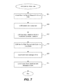
- FIG. 7 is a flow diagram describing one embodiment by which a virtual machine writes data to the storage platform.
- FIG. 8 is a symbolic representation of a virtual disk showing how data within the virtual disk is stored within the storage platform.
- FIG. 9 is a flow diagram describing one embodiment by which a virtual machine reads data from the storage platform.
- FIG. 10 is a flow diagram describing one embodiment by which failure recovery is performed.
- FIG. 11 illustrates how disks within the storage platform are organized into storage pools.
- FIG. 12 is a flow diagram describing an embodiment in which a read is performed of the virtual disk in the context of Snapshot and Revert commands.
- FIG. 13 is an illustration of how state variables version and version tree are updated during the course of commands concerning the virtual disk.
- FIG. 14 illustrates a more complex version tree for a particular virtual disk.
- FIG. 15 is a flow diagram describing an embodiment for cloning a virtual disk.
- FIG. 16 illustrates an architecture of the storage platform used to overcome throughput and latency problems with coordination software.
- FIG. 17 illustrates use of a distributed hash table in order to implement an embodiment of the present invention.
- FIG. 18 is a flow diagram describing an embodiment in which data may be written to one of many clusters within a storage platform.
- FIG. 19 is a flow diagram describing one embodiment by which a timestamp is generated.
- FIG. 20 illustrates how a timestamp is generated for a particular virtual disk whenever there is a write request.
- FIG. 21 illustrates how requests for a timestamp result in monotonically increasing values.
- FIGS. 22A and 22B illustrate metadata storage within the platform.
- FIG. 23 shows information that may be stored within a memory cache of a controller virtual machine (CVM) on one of the computer servers in the compute farm.
- CVM controller virtual machine
- FIGS. 24 and 25 illustrate a computer system suitable for implementing embodiments of the present invention.
- FIG. 1 illustrates a data storage system 10 according to one embodiment of the invention having a storage platform 20 .
- the storage platform 20 includes any number of computer nodes 30 - 40 .
- Each computer node of the storage platform has a unique identifier (e.g., “A”) that uniquely identifies that computer node within the storage platform.
- Each computer node is a computer having any number of hard drives and solid-state drives (e.g., flash drives), and in one embodiment includes about twenty disks of about 1 TB each.
- a typical storage platform may include on the order of about 81 TB and may include any number of computer nodes.
- One advantage is that a platform may start with as few as three nodes and then grow incrementally to as large as 1,000 nodes or more.
- Computers nodes 30 - 40 are shown logically being grouped together, although they may be spread across data centers and may be in different geographic locations.
- a management console 40 used for provisioning virtual disks within the storage platform communicates with the platform over a link 44 .
- Any number of remotely located computer servers 50 - 52 each typically executes a hypervisor in order to host any number of virtual machines.
- Server computers 50 - 52 form what is typically referred to as a compute farm.
- these virtual machines may be implementing any of a variety of applications such as a database server, an e-mail server, etc., including applications from companies such as Oracle, Microsoft, etc.
- These applications write to and read data from the storage platform using a suitable storage protocol such as iSCSI or NFS, although each application will not be aware that data is being transferred over link 54 using a generic protocol implemented by the present invention.
- Management console 40 is any suitable computer able to communicate over an Internet connection or link 44 with storage platform 20 .
- an administrator wishes to manage the storage platform (e.g., provisioning a virtual disk, snapshots, revert, clone, analyze metrics, determine health of cluster, etc.) he or she uses the management console to access the storage platform and is put in communication with a management console routine executing as part of metadata module 130 (shown in FIG. 2 ) on any one of the computer nodes within the platform.
- the management console routine is typically a Web server application.
- the virtual disk In order to provision a new virtual disk within storage platform 20 for a particular application running on a virtual machine, the virtual disk is first created and then attached to a particular virtual machine.
- a user uses the management console to first select the size of the virtual disk (e.g., 100 GB), and then selects the individual policies that will apply to that virtual disk. For example, the user selects a replication factor, a data center aware policy and other policies concerning whether or not to compress the data, the type of disk storage, etc.
- the virtual disk Once the virtual disk has been created, it is then attached to a particular virtual machine within one of the computer servers 50 - 52 and the provisioning process is complete.
- storage platform 20 is able to simulate prior art central storage nodes (such as the VMAX and CLARION products from EMC, VMWARE products, etc.) and the virtual machines and application servers will be unaware that they are communicating with storage platform 20 instead of a prior art central storage node.
- the provisioning process can be completed on the order of minutes or less, rather than in four to eight weeks as was typical with prior art techniques.
- the advantage is that one only need to add metadata concerning a new virtual disk in order to provision the disk and have the disk ready to perform writes and reads. No allocation of actual physical storage is needed.
- FIG. 2 illustrates software modules used within storage system 10 . Shown is a data module 120 , a metadata module 130 and a pod module 140 .
- Data module handles the storage of data (such as blocks of data, files, objects, etc.) onto individual computer nodes 30 - 40 .
- Metadata module handles the storage of metadata within the platform, that is, data that helps describe the data. Metadata includes all of the virtual disk information described below in FIG. 6 , for example.
- Pod module is a coordinator module and also stores transaction states as will be explained in greater detail below.
- each of the modules runs independently on each of the computer nodes within the platform 20 .
- a memory cache 122 , 132 and 142 that stores information used by that module; each module on each computer node may also use persistent storage on that node.
- a file (for example) that is stored on nodes 32 , 34 and 36 ( FIG. 1 ), is referred to as being stored on its “data nodes 32 , 34 and 36 .”
- the metadata for that file may be stored on three different nodes, and those nodes for that file are referred to as the “metadata nodes 30 , 36 and 38 .”
- the data nodes and metadata nodes for a particular stored file may be the same or may be different.
- the modules communicate with each other via a modified version of Gossip over Transmission Control Protocol (TCP), and work in concert to manage the storage platform.
- TCP Transmission Control Protocol
- FIG. 3 illustrates in more detail the nodes of platform 20 .
- each node includes a data module, a metadata module and a pod module.
- FIG. 4 illustrates in greater detail one of the computer servers 51 in communication with storage platform 20 .
- each computer server may host any number of virtual machines, each executing a particular software application.
- One advantage of the present invention is the ability of each virtual machine (or more specifically, the application executing on the virtual machine) to communicate with the storage platform using any of a variety of protocols.
- the application performs I/O handling using a block-based protocol such as iSCSI, or using a file-based protocol such as NFS.
- Each virtual machine may communicate with the storage platform using either of these protocols, and, the actual communication protocol used between server and platform is transparent to these virtual machines.
- other suitable protocols used by an application may also be used.
- One embodiment of the invention converges the possible protocols used by an application onto the single storage platform 20 .
- server 51 includes a hypervisor and virtual machines 182 and 186 that desire to perform I/O handling using respectively the NFS protocol 183 and the iSCSI protocol 187 .
- Server 51 also includes a specialized controller virtual machine (CVM) 180 that is specially adapted to handle communications with the virtual machines using protocols 183 and 187 , yet communicates with the storage platform using a proprietary protocol 189 .
- Protocol 189 may be any suitable protocol for passing data between storage platform 20 and a remote computer server 51 such as TCP.
- the CVM may also communicate with public cloud storage using the same or different protocol 191 .
- the CVM need not communicate any “liveness” information between itself and the computer nodes of the platform. There is no need for any CVM to track the status of nodes in the cluster. The CVM need only talk to a node in the platform, which is then able to route requests to other nodes and public storage nodes.
- the CVM also uses a memory cache 181 on the computer server 51 .
- a memory cache 181 on the computer server 51 .
- In communication with computer server 51 and with CVM 180 are any number of solid-state disks (or other similar memory) 195 . As discussed in further detail below with respect to steps 316 and 364 in FIG. 7 , these disks are used as a data cache to also store data blocks that are written into storage platform 20 . This cache may be used to rapidly retrieve data blocks instead of retrieving them from the remote storage platform.
- CVM 180 handles different protocols by simulating an entity that the protocol would expect. For example, when communicating with an NFS client, CVM behaves as an NFS server; when communicating under the iSCSI protocol, CVM responds to an iSCSI Initiation by behaving as an iSCSI Target.
- use of the CVM allows an application executing upon a virtual machine to continue using the protocol it expects, yet allows these applications on the various computer servers to write data to and read data from the same storage platform 20 .
- controller virtual machine When virtual machine 182 performs I/O handling the controller virtual machine is the NFS server and the NFS client (on behalf of virtual machine 182 ) executes either in the hypervisor of computer server 51 or in the operating system kernel of virtual machine 182 .
- virtual machine 186 When virtual machine 186 performs I/O handling, it is the iSCSI initiator and the controller virtual machine is the iSCSI target.
- the controller virtual machine During reads or writes, when either virtual machine 182 or 186 communicates with the controller virtual machine (either as an iSCSI target or as an NFS server), the controller virtual machine will convert this communication into its own protocol 189 in order to communicate with the storage platform. In this fashion, any of a variety of data storage protocols ( 183 , 187 , etc.) may be used to write data into and read data from the storage platform.
- the CVM when an application is using the block protocol, the CVM masquerades as the iSCSI target, traps the iSCSI Command Descriptor Blocks (CDBs), translates this information into its own protocol, and then communicates this information to the storage platform.
- CDBs iSCSI Command Descriptor Blocks
- the CVM masquerades as an NFS server, captures NFS packets, and then communicates this information to the storage platform using its own protocol.
- One of the virtual machines in computer server 51 may also communicate directly with the storage platform 20 (or with any data center) using a protocol such as Representational State Transfer (REST) in which the CVM is bypassed completely. But, such a technique would require the developer of the application running on the virtual machine to rewrite a substantial portion of that application.
- REST Representational State Transfer
- the application may simply talk to the underlying file system (in the case of NFS) or talk to a block device (in the case of iSCSI) as it would do normally.
- the application is unaware that the CVM is trapping and intercepting its calls under these protocols or that the CVM even exists.
- the advantage is that an application need not be changed in order to write to and read from the storage platform.
- FIG. 5 is a flow diagram describing one embodiment by which an administrator provisions a virtual disk within platform 20 .
- the administrator is aware that a particular virtual machine desires a virtual disk within the platform and is aware of the characteristics that the virtual disk should have.
- the administrator first uses the management console to access the platform and connect with the management console Web server on any one of the computer nodes within the platform.
- FIG. 6 illustrates a user interface window 220 presented to an administrator in the course of provisioning a virtual disk.
- the administrator chooses the “Add Disk” option from within the management console routine and is presented with a window such as shown in FIG. 6 .
- the administrator uses window 220 in order to choose the characteristics of the new virtual disk.
- the administrator chooses: a name 224 for the new virtual disk; a size 226 for the virtual disk; a replication factor 228 (indicating how many replicas of the data should be stored within the platform); a residence 230 (indicating whether the data on the virtual disk should be stored on hard disk drives, on flash drives or on any other type of storage drive); compressed 232 (indicating whether the data on the virtual disk should be compressed or not); de-duplication 234 (indicating whether duplicates of the data should be saved to the virtual disk or not); a replication policy 236 (agnostic, data center aware, rack aware, or hybrid cloud aware); cache enabled 238 (a quality of service choice); and disk type 240 (indicating whether the virtual disk is of a block type—the iSCSI protocol—or whether the virtual disk is of a file type—the NFS protocol). Concerning the Disk Type 240 , this information is saved so that the CVM is aware of whether it should masquerade as a block device or as an NFS device in order to communicate with the application that wishes to write to or
- Replication policy 236 may be “agnostic,” meaning that the virtual disk (or rather, the application on the virtual machine or the owner of the virtual disk) does not care on which rack or in which data center the replicas are stored. If the policy is “rack aware” this means that more than one replica may not be stored on the same rack within a particular data center.
- the rack aware policy refers to the fact that computers within a data center are typically clustered into racks. Typically, there are twenty computer servers per rack or as many as forty. On the top of each rack is a network switch used to route information between the various computer servers (also called a “top-of-the-rack switch”). Should this switch fail then all the data located on the computer servers within the rack will become inaccessible or may be lost.
- an application may desire that its replicas not be stored in the same rack. Choosing the rack aware policy then, requires that no more than one replica of a particular virtual disk be stored on a single rack. If the policy is “data center aware” this means that replicas must be distributed between data centers in geographically different locations. If the policy is “hybrid cloud aware” this means that at least one replica must be stored within public cloud storage 190 , in addition to the other replicas stored within storage platform 20 .
- replicas of a virtual disk may be stored within public cloud storage 190 .
- public cloud storage refers to those data centers operated by enterprises that allow the public to store data for a fee. Included within these data centers are those known as Amazon Web Services and Google Compute.
- the write request will include an identifier for each computer node to which a replica should be written. For example, nodes may be identified by their IP address.
- the computer node within the platform that first fields the write request from the CVM will then route the data to be written to nodes identified by their IP addresses.
- Any replica that should be sent to the public cloud can then simply be sent to the DNS name of a particular node which request (and data) is then routed to the appropriate public storage cloud. Any suitable computer router within the storage platform may handle this operation.
- step 212 these characteristics are stored as “virtual disk information” 260 onto computer nodes within the storage platform.
- this virtual disk information is replicated and stored on at least three different computer nodes.
- the metadata module 130 on these three computer nodes handles the storage of this information by placing it into persistent storage as shown in FIGS. 22A and 22B .
- a hash function is used upon the virtual disk name 224 in order to produce a hash value which is then used to select three computer nodes within the platform.
- the virtual disk information for the newly created virtual disk may be stored upon nodes 36 , 30 and 40 .
- step 212 stores this information in metadata 862 of metadata module storage as shown in FIG. 22A .
- this metadata module and its associated storage may be present on any of the computer nodes of the platform.
- virtual disk information metadata 862 is replicated upon other metadata modules on other computer nodes.
- step 216 in FIG. 5 the virtual disk that has been created is attached to a virtual machine of the compute farm.
- the administrator is aware of which virtual machine on which computer of the compute farm needs the virtual disk.
- information regarding the newly created virtual disk i.e., name, space available, etc.
- the information is provided to the controller virtual machine 180 which stores the information in cache 181 , ready for use when the virtual machine needs to write data.
- the administrator also supplies the name of the virtual disk to the application that will use it. At this time, no information need be sent from the storage platform or from the CVM to the application.
- step 216 the virtual disk information which had been stored onto the metadata nodes in step 212 is also sent to the controller virtual machine which caches this information for later use.
- the identities of the metadata nodes which store this metadata for the virtual disk is also sent to the controller virtual machine.
- the controller virtual machine is aware of on which compute nodes of the storage platform the metadata for a particular virtual disk is stored as shown in FIG. 23 .
- the virtual disk has been provisioned and is ready for use. Note that the actual nodes and disks within the storage platform have not been allocated yet; such allocation will occur when the virtual machine writes data.
- FIG. 7 is a flow diagram describing one embodiment by which a virtual machine writes data to the storage platform.
- FIG. 8 is a symbolic representation of a virtual disk 330 showing how data within the virtual disk is stored within the storage platform and will be referred to in the description of FIG. 7 .
- the virtual disk has been provisioned as a disk holding up to 50 GB, and the disk has been logically divided into segments or portions of 16 GB each. Each of these portions is termed a “container,” and may range in size from about 4 GB up to about 32 GB, although a size of 16 GB works well.
- the first portion 332 is referred to as container one, or C 1
- the latter portions 334 - 338 are referred to respectively as containers C 2 , C 3 and C 4 .
- the final container may have a size less than the sizes of the other containers.
- Containers have a particular naming convention. In one implementation, the convention is that the first container of a virtual disk will have a name that is the concatenation of: virtual disk name, “$” and “1.” The second container of that virtual disk will have a nearly identical name except that the final symbol will be a “2.” In this fashion, by knowing the container name, one knows with which virtual disk the container is associated. In addition, by knowing the virtual disk name, and an offset and size, one will be able to determine the names of the containers associated with a particular write request. In this fashion, each container name is unique within the entire storage platform.
- each container of data will be stored upon a particular node or nodes within the storage platform that are chosen during the write process. If no replication is chosen, then data within a particular container will be stored on one node, while if replication is two, for example, then data within that container will be stored upon two nodes. In the example of FIG. 8 , the replication factor is three, thus, data stored within container 332 will be stored upon the three nodes A, B and F. Any data stored within the second container 334 will be stored upon the three nodes B, D and E. Note that the set of nodes 342 and 344 might be the same nodes, may be completely different nodes, or may have nodes in common.
- step 304 in FIG. 7 the virtual machine that desires to write data into the storage platform sends a write request including the data to be written to a particular virtual disk (supplied to the application by the administrator earlier).
- a write request may originate with any of the virtual machines on one of computer servers 50 - 52 and may use any of a variety of storage protocols.
- the write request typically takes the form: write (offset, size, virtual disk name).
- the parameter “virtual disk name” is the name of the virtual disk originally selected in step 208 in FIG. 5 .
- the parameter “offset” is an offset within the virtual disk (i.e., a value from 0 up to the size of the virtual disk), and the parameter “size” is the size of the data to be written in bytes.
- the CVM will trap or capture this write request sent by the application (in the block protocol or NFS protocol).
- step 308 the controller virtual machine determines which containers to use for this request based upon the offset and size parameters. For example, because the CVM is aware of the size of each container (typically 16 GB), knowing the offset and the size of the write request, the CVM is able to determine which container shall be used and whether more than one container is needed. Each container is provided with a unique identifier within the platform, and containers used to write to other virtual disks will also have an identifier unique within the platform. Assuming that only one container is needed (for example, C 2 ), the CVM then proceeds to determine on which computer nodes of the storage platform the data should be stored.
- the CVM determines which containers to use for this request based upon the offset and size parameters. For example, because the CVM is aware of the size of each container (typically 16 GB), knowing the offset and the size of the write request, the CVM is able to determine which container shall be used and whether more than one container is needed. Each container is provided with a unique identifier within the platform, and containers used to write
- step 312 the CVM queries a metadata node to determine on which computer nodes the container should be stored. Because the particular metadata nodes on which the metadata for the virtual disk is stored had been previously cached by the CVM, the CVM can easily select one of these metadata nodes to query.
- the CVM sends a query with the container to be used (e.g., C 2 ) and requests the return of a list of the actual data nodes on which to write that container. If that container had previously been written to that virtual disk then the metadata node knows which data nodes to return because it had previously stored that information. If this is a first write request for a particular container, then the metadata node determines which and how many computer nodes to assign to that container based upon how many replicas are needed.
- the metadata node retrieves or determines the data nodes to use for the write request, it then returns a list to the CVM (e.g., it returns a list of these nodes 344 : B, D and E). The CVM is now ready to perform the write request.
- step 316 the CVM then sends the write request (in this case, simply the data itself to be written) to one of the data nodes returned in the previous step (e.g., data node E).
- the write request also includes an indication of the other two data nodes (B, D) to which the data should be written.
- the data node that receives the request then writes the data to its disk drives and then forwards the data to the other two nodes. Once each of these nodes writes the data to its disk drives, each of these nodes returns an acknowledgment back to the first data node that had originally received the request from the CVM.
- the CVM also sends with the write request the relevant policies for the particular virtual disk. For example, the CVM indicates how many replicas are needed, the type of storage disk required, whether the data should be compressed, what the replication policy is, etc. The data node that receives the request will then handle implementations of all of these policies. The CVM does not need to concern itself with how these policies are implemented; it simply sends the write request with the relevant information.
- step 316 because the CVM has a cache 181 that contains the current version and version tree for each virtual disk that is attached to it (i.e., for each virtual disk used by the virtual machines on the same computer as the CVM), the CVM is also able to send the current version of the virtual disk with the write request so that as blocks of the virtual disk are written onto their data nodes the current version may be stored along with each block. Versions and version trees of virtual disks are discussed in more detail below with respect to FIGS. 12-14 . A timestamp is also sent with the write request.
- the CVM In addition to writing the data over an Internet connection to data nodes within a remote storage platform 20 , the CVM also writes the same data blocks into solid-state storage 195 in FIG. 4 (a block cache) so that the data blocks may be read from this cache much more quickly if needed.
- the data blocks are identified within this cache preferably using the block identifiers.
- this first data node (e.g., E) acknowledges that the write has occurred to the CVM and returns the names of the data nodes (e.g., B, D and E) where the data was written.
- step 324 the CVM then calculates the block identifiers (i.e., blocks 1, 2, 3) within the virtual disk where the data has been stored and then saves this information into the metadata nodes associated with the virtual disk.
- disks are typically divided up into blocks (usually blocks of 4K) and data is written to, and read from, disks using blocks. Because the CVM is aware of the offset for the write request, the CVM then knows the block identifier for the first block to be written for the current write request. And, because the size of the write request is also known, the CVM is then able to easily calculate onto which data nodes blocks of data were written, and the corresponding block identifiers for those blocks of data.
- the CVM calculates the block identifiers for those blocks of data in the current write request which were written to nodes B, D and E. Even if a write request spans two different containers, by simple calculation using the container size, offset, and size of the write request, the CVM will be able to determine which block identifiers were written to the first container and which block identifiers were written to the second container.
- the CVM then stores these block identifiers where the current write was successful into the three metadata nodes holding the metadata for the current virtual disk as shown in FIG. 22B .
- these three metadata nodes are always aware which block identifiers have been written for this particular virtual disk.
- other virtual disks that have been created within the storage platform may use different sets of three metadata nodes (or perhaps fewer or more metadata nodes) in order to store their metadata.
- step 324 the locations of the containers (nodes and storage pools) are also written into the metadata modules associated with that virtual disk.
- step 324 the CVM also sends the current version of the virtual disk with the block identifiers so that the current version may be stored along with the block identifiers in the metadata nodes as shown in FIG. 22B .
- the CVM also generates a timestamp and includes this timestamp along with the block identifiers so that each block includes a timestamp in metadata.
- a timestamp may be generated in a variety of manners. In one preferred embodiment, a timestamp is generated as discussed below with respect to FIGS. 19 and 20 .
- write operations do not overwrite older versions of data.
- earlier versions of data in a virtual disk are always available to be read.
- snapshot and revert operations can be performed very quickly because data does not need to be copied into special storage locations or retrieved from special storage locations. All versions of data are always available within the storage platform.
- blocks of data are stored as “chunks,” each chunk including in its name the version number which identifies the version of the data stored.
- FIG. 9 is a flow diagram describing one embodiment by which a virtual machine reads data from the storage platform.
- step 364 the virtual machine that desires to read data from the storage platform sends a read request from a particular application to the desired virtual disk.
- the controller virtual machine will then trap or capture the request (depending upon whether it is a block request or an NFS request) and then places a request into its own protocol before sending a request to the storage platform.
- a read request may originate with any of the virtual machines on computer 51 (for example) and may use any of a variety of storage protocols.
- the read request typically takes the form: read (offset, size, virtual disk name).
- the parameter “virtual disk name” is the name of a virtual disk on the storage platform.
- the parameter “offset” is an offset within the virtual disk (i.e., a value from 0 up to the size of the virtual disk), and the parameter “size” is the size of the data to be read in bytes.
- the CVM first checks its block cache 195 to determine whether any of the blocks to be read are already present within this cache. If so, these blocks are retrieved from block cache 195 instead of having to establish a remote connection with storage platform 20 and retrieve those blocks remotely which would take a greater deal of time.
- step 368 the controller virtual machine determines which container or containers to read from for this request based upon the offset and size parameters as described above.
- the CVM also determines the block identifiers that it needs to read using the offset and the size from the request.
- step 372 the CVM queries a metadata node to determine on which computer nodes the data blocks identified by the block identifiers are written. Because the particular metadata nodes on which the metadata for the virtual disk is stored had been previously cached by the CVM, the CVM can easily select one of these metadata nodes to query.
- the CVM sends a query with a container identifier (e.g., C 2 ) and requests the return of a list of the actual computer nodes on which the data had been written.
- the metadata node knows which data nodes to return because it had previously stored that information in step 324 ( FIG. 7 ); see, for example, FIG. 23 .
- the metadata node retrieves the data nodes where the data blocks were stored, it then returns a list to the CVM (e.g., it returns a list of these nodes 344 : B, D and E). The CVM is now ready to perform the read request.
- step 376 the CVM then sends the read request to each of the data nodes returned in the previous step.
- the read request includes a list of block identifiers to be read and a timestamp.
- a timestamp with a read request is useful for the following reasons. As mentioned above, performing a write request for a particular container to any number of data nodes may result in success or failure. If the result indicates failure, then the CVM will not update the relevant metadata nodes to indicate that the write was actually performed. Nonetheless, it is possible that the data might have been written to at least one data node within the storage platform. Upon a subsequent read operation of that same container, is important not to read the information that might have been written to a node during the failed write operation.
- the read request will include a timestamp from the previous successful write operation in order to avoid reading the wrong data. Because every successful write operation records the timestamp of that successful write operation into the relevant metadata nodes, the CVM can obtain this timestamp for the last successful write operation in step 372 .
- the CVM sends along with the read request all version numbers for the data that it is requesting along with the version tree. How to obtain these version numbers is discussed in more detail below with respect to FIG. 12 .
- the version number is useful because the particular read request will need to read from the current version using the version tree, backtracking to the root of the tree as explained below. This technique provides the requesting application with the correct version from the virtual disk.
- each data node returns the data identified by the block identifiers to the CVM.
- the CVM then returns this data to the requesting virtual machine using the appropriate protocol 183 or 187 , again masquerading either as a block device or as an NFS device depending upon the protocol used by the particular application.
- the read request is sent to only one of the data nodes (e.g., B) and also includes an indication of the other two data nodes (D, E) from which the data should be read.
- the first data node then passes the read request to each of the other data nodes.
- Each of these data nodes that receives the request then reads the data from its disk drives. Once each of these nodes reads the data from its disk drives, each of these nodes returns the data back to the first data node that had originally received the request from the CVM. This first data node then returns the data to the CVM.
- a storage pool migration technique that allows many, if not all, of the computer nodes within a storage platform to participate in the data reconstruction, thus leading to faster recovery.
- the data will be reconstructed using all of the relevant policies of the virtual disk from which that data is a part. Lost data from a failed disk is reconstructed quickly and applications that rely upon the storage platform are not degraded.
- FIG. 10 is a flow diagram describing one embodiment by which this failure recovery is performed.
- FIG. 11 illustrates how disks within the storage platform are organized into storage pools and will be discussed in the context of the flow diagram of FIG. 10 .
- Shown is one computer node 30 of the storage platform having a unique identifier “A.”
- each computer node Associated with, and under the control of, each computer node are any number of hard drive or solid-state disks. Shown are nine disks that are organized into groups of three, each group forming a storage pool 454 , 456 or 458 . Of course, more or fewer disks may be associated with each node, there may be more or fewer storage pools, and the number of disks within each storage pool may vary.
- Each storage pool within the platform also has a unique identifier such as “storage pool 1 ,” etc. As earlier discussed, when an application writes data to its virtual disk that data will be assigned to a particular container and that container will be written to a particular node or nodes (as shown in FIG. 8 ).
- containers written to a particular disk will necessarily be assigned to a particular storage pool.
- containers C 1 , C 3 and C 8 have previously been written into a disk or disks within storage pool 454 .
- Various implementations may be used to write a container into a storage pool.
- One technique simply writes a particular container onto a single disk within the storage pool.
- a given container is written to a storage pool by spreading the blocks of a container across all of the disks within that storage pool.
- other techniques used to write blocks of data onto a disk or disks may also be used.
- FIGS. 22A and 22B illustrates persistent storage of a metadata module 130 executing upon a particular computer node within the platform.
- each computer node includes an executing metadata module each storing metadata concerning nodes, virtual disks, etc.
- persistent storage for node A (for example) includes metadata 862 concerning the virtual disk named “Avinash.”
- other metadata may also be stored within this storage. The contents of this persistent storage will be discussed in more detail below.
- the metadata for each computer node within the storage platform are determined at any suitable time.
- a computer node such as node “A” will have its metadata stored on at least one computer node within the platform, and preferably three.
- This metadata will be stored using the metadata module executing upon each node and stored within persistent storage associated with each metadata module.
- the metadata nodes for a particular computer node are determined by using a hash function on the unique identifier for a particular node to produce a hash value. This hash value is then used to identify three computer nodes within the platform that will be the metadata nodes for that particular node.
- FIG. 22A shows that metadata module persistent storage stores metadata on computer node “A.”
- Step 404 also includes storing the storage pool identifiers and the disk identifiers for each node into the metadata module storage.
- metadata 860 includes the unique identifiers of the storage pools (e.g., “SP 1 ”) associated with node “A” as well as the unique identifiers for each disk (e.g., “D 1 ”), and in which storage pool each disk belongs.
- Metadata 861 also includes container information showing which containers are stored within each storage pool; in this example, container Vi$2 is stored in storage pool SP 3 .
- Step 404 is performed for each computer node within the platform and may be performed at any suitable point in time, preferably when the platform is first initialized, or when containers are written.
- step 408 at some point in time the failure of a disk is detected within the platform. This failure may be detected in many ways. When a disk fails, it is assumed that the data present on that disk is lost and that the data should then be reconstructed as there may not be enough replicas of the data according to the replication factor of the virtual disk of which the data was a part.
- step 412 the storage pool that includes the failed disk is disabled. For example, assuming that disk D 2 has failed, then the module will disable storage pool 454 because disk D 2 is part of that storage pool. In this embodiment, the entire storage pool is disabled rather than simply disabling the failed disk. Disabling a storage pool means that no more data will be written to any of the disks within that pool and that no more reads will be performed from that pool.
- the data modules 120 are responsible for performing storage pool migration.
- step 416 the module determines which containers are present on the disabled storage pool and therefore, which containers must be reconstructed. Because it is known which particular disk has failed and which storage pool has been disabled, the module may then reference metadata 861 (for example) to determine which containers have been lost. For example, knowing that disk D 2 has failed on computer node “A” the module finds the metadata module storage for node “A” and determines that containers C 1 , C 3 and C 8 have been lost. As shown in FIG. 11 , containers 460 have unique identifiers within the storage platform and these containers may be part of any of the virtual disks stored within platform. In other words, containers C 1 , C 3 and C 8 may be part of different virtual disks, or, they may all be part of the same virtual disk.
- Step 420 begins a loop that iterates over each of the lost containers using the unique identifier for each lost container.
- a candidate computer node within the storage platform is selected to hold a new replica of the lost container that respects the policies of the virtual disk that includes the lost container. For example, given the unique identifier of a lost container, the module then references metadata 862 to determine the relevant policies of that virtual disk that must be complied with. Because the container identifier includes the virtual disk name, the module then knows the virtual disk name and can find its virtual disk information on the appropriate metadata node. In this example, the candidate node must comply with the Replication policy and the Residence policy of virtual disk Avinash.
- the Replication policy states that each of the three replicas of the virtual disk must be stored in a geographically separate data center (“data center aware”), this means that the candidate node must not be located in a data center where the remaining two replicas are located. If the Replication policy states that replicas must be stored in different racks (“rack aware”), this means that the candidate node must not be located in a rack where the remaining two replicas are located. If the Replication policy states that at least one replica must be located in public cloud storage (“hybrid cloud aware”), this means that the candidate node must be located in public cloud storage if one of the other replicas is not already located there.
- Complying with the Residence policy means that the candidate node must have disks of a type specified in the Residence policy, i.e., hard disks or solid-state disks on which the entire container can be stored. Of course, there may be other policies that must also be complied with.
- the information that describes the Replication and Residence characteristics of each node may be found by querying each node, by looking at the metadata for a particular node, or using other suitable techniques.
- the lost container is copied from one of its remaining replicas onto the selected node. For example, if it is known that computer nodes “B” and “C” hold replicas of the lost container, then one of these replicas may be used to copy a new replica onto the selected node. If node A respects the policies then it may be used as the selected node even though it is the node where the disk just failed, i.e., another storage pool on node A may be selected even though a storage pool on node A just failed. In an alternative embodiment, no storage pool on node A may be used as it may be unclear why one of the storage pools failed.
- the metadata module storage corresponding to that computer node is now updated with the new information. For example, if container C 1 has now been written to node “D” then the metadata module storage associated with node “D” is then updated to reflect that container C 1 is now present within a particular storage pool of that node.
- snapshots may be used in the development of a particular software application. If the application (and its data) are executing successfully at a particular point in time, a snapshot of the software application and of its data at that time may be taken before any new features are added, before a new version is introduced, before the data is changed, or before other changes occur that might corrupt the data. If corruption of the data (or of the application) occurs, then one simply reverts to the snapshot of that data before the corruption occurred.
- This embodiment of the present invention provides techniques for creating a snapshot of a virtual disk (recording a version of that disk at a particular point in time) and for reverting to that earlier version of the virtual disk (the snapshot) that is not dependent upon the size of the virtual disk or the amount of data it contains. No data of the virtual disk needs to be copied during either the snapshot command or the revert command. The result is data protection that is simple, fast and inexpensive.
- the data of the virtual disk may be data of an application, source or object code of the application, etc.
- an implementation may be used such as shown in FIG. 22B , in which blocks (or chunks) of data having different versions are stored in different locations, i.e., particular versions of particular blocks are not overwritten within the platform.
- FIG. 12 is a flow diagram describing an embodiment in which a read is performed of the virtual disk in the context of Snapshot and Revert commands.
- FIG. 13 is an illustration of how state variables version 554 and version tree 556 are updated during the course of commands concerning virtual disk 552 . This figure will be discussed in greater detail below in the context of the steps of FIG. 12 .
- step 504 while a particular virtual disk is being provisioned, its version number and version tree are initialized. This initialization may be performed during step 212 ( FIG. 5 ) and involves updating metadata 862 (for this particular virtual disk, for example) so that the version is set equal to “1” and the version tree data structure includes only the root, also with the value of “1.” Further, in step 216 (again see FIG. 5 ) the version and version tree are also stored into cache 181 ( FIG. 4 ) of the controller virtual machine along with the rest of the virtual disk information.
- FIG. 13 A symbolic representation of commands given to this virtual disk and of how the values for its version and version tree change as these commands are given are shown in FIG. 13 . Shown symbolically is a particular virtual disk 552 and listed below it vertically are a sequence of Snapshot and Revert commands issued to this virtual disk. Version 554 shows how the version changes as these commands are given, and Version tree 556 shows how the version tree data structure changes as well. As shown at state 560 , once the virtual disk has been provisioned it has a version equal to “1” and its version tree is simply the root 570 . Any number of write requests and read requests (and other commands) may be issued to the virtual disk yet the virtual disk remains in state 560 in which its version is “1” and its version tree is root 570 .
- an application developer, administrator, or other entity that controls the virtual disk may desire to issue a Snapshot command for that virtual disk.
- a Snapshot command is issued for the virtual disk and may be issued using the management console or a command line interface.
- the Snapshot command takes one parameter which is the name of the virtual disk.
- This command causes the version for that virtual disk to increase in step 512 and also causes a branch to be added the version tree in step 516 .
- FIG. 13 illustrates these changes caused by issuance of the Snapshot command.
- virtual disk (column) 552 the virtual disk enters into a new state 562 in which the version is changed to “2” and the version tree has a new node “2” added with a link back to the root “1” as shown at 572 .
- Snapshot command returns the name of the Snapshot which includes the version at the time the command was issued (i.e., before the version is increased) and the name of the virtual disk.
- the Snapshot command returns a Snapshot name which is “Snap$1 ⁇ Avinash.”
- Other descriptive information may also be added by the administrator when issuing the Snapshot command and would become part of the Snapshot name.
- the upshot of increasing the version by one is that any write requests performed for this virtual disk after the Snapshot command has been issued will be written with the new version, namely “2.”
- the updated version tree 572 indicates symbolically that version “2” is based upon version “1.”
- this version tree may be implemented in the memory of the metadata module storage and in the cache of the CVM using any appropriate data structure.
- commands may be issued to the virtual disk such as write requests and read requests, and these commands will take place in the context of state 562 , namely that the current version of the virtual disk is version “2.”
- the administrator may wish to revert to an earlier state (or version) of the virtual disk.
- an earlier state or version
- the name of that snapshot is “Snap $1 ⁇ Avinash.”
- Any of a variety of schemes may be used for recording snapshot names, particular version numbers, relevant events, etc. Because a snapshot name includes its version number and the name of the virtual disk, it can be a simple matter to decide which snapshot to use when a particular earlier version is desired.
- an administrator issues a Revert command that includes a particular snapshot name, for example, “Revert Snap$1 ⁇ Avinash.”
- the virtual disk now enters state 564 , the version is changed to “3” in step 528 , and the version in the metadata nodes tree has a new branch added in step 532 so that it appears as shown in version tree 574 . From this point forward, any write requests will be in the context of version “3.”
- the new version tree 574 when a Revert command is given a new branch is added having the new version number “3,” the branch has a reference back to the version that was in place for the snapshot desired.
- step 536 describes how a read request is performed in the context of version numbers from the version tree.
- an application on a virtual machine requests to read from a virtual disk the flow will occur as described in FIG. 9 except that the CVM will provide a version number along with the read request in step 376 .
- the CVM will first access the version tree data structure for the particular virtual disk stored within its cache (or optionally may retrieve this data structure in step 372 from the metadata node).
- the CVM will start at the current version (in this case, version “3”) and then walk through the existing links all the way back to the root, collecting version numbers as it goes. In this case, the CVM collects versions “3” and “1”.
- FIG. 14 illustrates a more complex version tree for a particular virtual disk.
- the version tree is simply the root as shown at 570 , and any I/O handling occurs in the context of this version.
- the administrator issues a Snapshot command while in version 1; the version of the virtual disk is incremented to “2” and the version tree now appears as shown at 580 .
- the administrator issues another Snapshot command while in version 2; the version is incremented to “3” and the version tree now appears as shown at 582 .
- the administrator issues a Revert command back to version “2” while in version “3;” the version is incremented to “4” and the version tree now appears as shown at 584 .
- Branch “4” references back to branch “2” because the Revert command wanted to revert back to version “2.”
- the administrator issues a Snapshot command while in version “4;” the version of the virtual disk is incremented to “5” and the version tree appears as shown at 586 .
- the administrator issues another Snapshot command while in version 5; the version is incremented to “6” and the version tree then appears as shown at 588 .
- the version tree includes all branches or versions 1-6; branches 7-9 are yet to be added.
- any read request will include the version numbers 9, 4, 2 and 1, as these are the version numbers found in the version tree as the CVM walks back through the tree from the current version to the root.
- Snapshot and Revert commands may be executed that do not depend upon the amount of data in the virtual disk; these commands may be executed within milliseconds as the only two operations needed are the updating of the version and the updating of the version tree. Because older versions of data blocks are always saved and not overwritten, these older versions are always available and data need not be copied or saved when a snapshot command is given. Likewise, when a revert command is given, data need not be copied from a special storage location back into the virtual disk because all versions of all data stored are always present within the platform.
- FIG. 15 is a flow diagram describing an embodiment for cloning a virtual disk.
- this embodiment provides a technique by which the clone of a virtual disk may be created with all of the same parameters and policies of the parent virtual disk, or, entirely new and different parameters and policies may be provided for the same data.
- a clone of a virtual disk may specify different media on which the data of the clone should be stored (e.g., solid-state drives instead of hard disk drives), may specify different physical locations for the data (e.g., a data center aware policy instead of an agnostic policy), etc.
- policies are implemented when new data is written to the clone disk. For example, if the parent virtual disk is all stored on hard disk drives, when the clone virtual disk is created all of its information by default will all be stored on hard disk drives as well, even if the clone virtual disk specifies solid-state drives. If only read operations are performed, the reads will always be from hard disk drives. Data will be written to solid-state drives as specified by the clone virtual disk when writes occur. The same holds true for the data center and rack aware policies as well. Thus, the different policies are implemented when data is written to the clone disk. As mentioned earlier, a write request includes the policies for a virtual disk (from the CVM cache) to ensure that data is written to a virtual disk using the correct policies.
- test database looks and feels very similar to the production database.
- This embodiment of the invention is able to take a snapshot of the production database on the virtual disk, make a clone of that virtual disk, and store changes to the database onto hard drives instead of onto the solid-state drives.
- the test database and any changes to it will reside on media that is less expensive than solid-state drives.
- an administrator desires to create a copy of a virtual disk within the storage platform and issues a command to clone the virtual disk.
- the clone command may be given from the management console and typically takes the form “Clone—virtual disk name—snapshot name—metadata properties.”
- the “virtual disk name” is the name of the virtual disk to be copied and is known as the parent virtual disk.
- the “snapshot name” is the name of a particular snapshot that has been created for the parent virtual disk and is explained in more detail with respect to step 508 in FIG. 12 .
- a snapshot of a virtual disk is created when the virtual disk is in the context of the current version; this current version becomes part of the snapshot name that the module returns to the administrator.
- any clone virtual disk created from a parent virtual disk using snapshot “5” will include all of the information included in that parent virtual disk up to and including version “5.”
- the parameter “metadata properties” allows the administrator to specify any of the parameters and policies shown in FIG. 6 , for example, and includes any other parameters or policies that can be specified when adding a new virtual disk.
- the command in step 604 may specify that the clone virtual disk must use compression, that its data should be stored upon solid-state drives, that its replication factor should be five, that its replication policy should be hybrid cloud data center aware, etc. These parameters and policies may be different from that of the parent virtual disk or they may be the same.
- the clone virtual disk is provisioned as is any new virtual disk according to steps 212 and 216 ( FIG. 5 ) including providing the clone disk with its own unique name.
- three metadata nodes will be chosen for this clone virtual disk and its clone virtual disk information will be stored in storage of these metadata nodes such as is shown at metadata 862 ( FIG. 22A ).
- the clone virtual disk will be attached to the same virtual machine as the parent virtual disk.
- the clone virtual disk may also be attached to a different virtual machine on a different computer on direction by an administrator.
- the clone virtual disk also receives its own version (“1” to begin with) and its own version tree. Notably, creating the clone virtual disk from the parent virtual disk does not involve copying any data from the parent virtual disk. When writes occur information will be written to the clone virtual disk, but reading will occur from the parent virtual disk unless a write request has previously written to the location in the clone disk where the read will occur.
- step 612 the name of the parent virtual disk and the snapshot version used are recorded for future use. Both are retrieved from the clone command. Because the cloned virtual disk was created from a particular version of the parent virtual disk at a particular point in time, it will be necessary to refer to the version tree of the parent virtual disk when performing certain read operations. Preferably, the parent virtual disk and version are recorded in the relevant metadata node for the clone virtual disk.
- step 616 the virtual machine to which the clone virtual disk has been attached writes to the clone virtual disk. This step may be performed as previously described with respect to FIG. 7 . Note that writing to a clone virtual disk does not write data into the parent virtual disk.
- the clone virtual disk is a separate virtual disk within the storage platform. All data written to the clone virtual disk is placed into containers associated with the clone virtual disk.
- step 620 the virtual machine to which the clone virtual disk has been attached reads from the clone virtual disk. This step generally follows the flow shown in FIG. 9 ; if data is found in step 624 (container locations are found in step 372 in FIG. 9 ), then in step 628 ( FIG. 15 ), the data is read from the clone virtual disk.
- step 624 if an attempt is made to read from the clone virtual disk at a particular offset and no data is found in step 624 , then the data must be read from the parent virtual disk.
- the relevant metadata node for a particular virtual disk will record that the write has been performed for a particular portion or container of that virtual disk.
- querying the metadata node in step 372 does not find that a write had been performed for this portion or container, this means that no data has been written to the clone virtual disk as of this time, and the following steps are performed.
- the parent virtual disk name and its snapshot version are retrieved from the location where they were stored in step 612 , that is, in the metadata node for the clone virtual disk.
- the clone virtual disk was created from a particular snapshot of the parent virtual disk, any read must take place from the version where the snapshot was created. Accordingly, the name of the parent virtual disk is used to find the correct metadata node that holds the metadata for that parent virtual disk, and from there the version tree for that parent virtual disk is retrieved. Next, using the version from the clone command, the version tree of the parent virtual disk is walked from that version back to the root to obtain the appropriate version numbers for a read operation. For example, if a clone virtual disk was created based upon Snapshot “5” of a parent virtual disk having a version tree such as is shown in FIG. 14 , then the correct version numbers to supply to the read request are 5, 4, 2, 1. These version numbers are then used to perform a read request from the parent virtual disk as per steps 368 - 384 ( FIG. 9 ). The offset and size parameters were originally supplied in the read request at step 620 ( FIG. 15 ).
- FIG. 1 also illustrates how the computer nodes of the storage platform may be organized into various clusters. Shown are two clusters, 62 and 64 , that each include three computer nodes. Coordination between nodes such as those of storage platform 20 that provides distributed storage can be difficult. A number of software products may be used to provide this coordination.
- One in particular is “Apache ZOOKEEPER,” an open source project that provides centralized infrastructure and services across a single cluster of computer nodes for storage of data.
- ZOOKEEPER provides a configuration service, a synchronization service, a naming service, and other services that can used by an application to ensure that tasks across the cluster are serialized or synchronized.
- ZOOKEEPER provides a configuration service, a synchronization service, a naming service, and other services that can used by an application to ensure that tasks across the cluster are serialized or synchronized.
- ZOOKEEPER may be used to store data into a single cluster of computer nodes, if there is more than one cluster of nodes these clusters will be independent and will not be able to coordinate storage between themselves. An improved system that provides for greater throughput is desirable.
- the ZOOKEEPER software is an example of replicated PAXOS instance software, and is an implementation of the prior art “Chubby Service.”
- FIG. 16 illustrates an architecture 700 of the storage platform 20 used to overcome throughput and latency problems with coordination software such as ZOOKEEPER.
- coordination software such as ZOOKEEPER.
- clusters 702 and 704 are used to provide greater throughput for the entire platform. Shown are clusters 702 and 704 . Of course, there may be many more such clusters within a particular platform. And, although three machines are shown in each of the clusters, typically a cluster includes anywhere from three to five machines, or more.
- each computer node of cluster 702 includes a ZOOKEEPER instance which is in communication with the other instances within cluster 702 (not shown for clarity is a bidirectional link between node 30 and node 34 ).
- the pod module of each computer node incorporates the ZOOKEEPER instance as well as other software.
- Another ZOOKEEPER cluster 704 is also shown. Unlike the prior art, though, the various ZOOKEEPER clusters can communicate with one another as described below, and thus appear as a single ZOOKEEPER cluster. Each cluster is aware of the other clusters.
- the speed with which data objects can be written to storage platform 20 is increased by a factor of two in this example. If there were four ZOOKEEPER clusters (for example), the speed would then be increased by a factor of four over use of a single traditional ZOOKEEPER cluster, etc.
- a software application (such as one of the applications executing within the compute farm) can simply perform a write to what it thinks is a single ZOOKEEPER cluster, when in actuality there may be any number of ZOOKEEPER clusters all operating in concert to write the data as quickly as possible.
- Other entities that may write to a ZOOKEEPER cluster include one of the modules of the platform, a controller virtual machine, one of the metadata nodes, one of the data nodes, etc.
- FIG. 17 illustrates use of a distributed hash table in order to implement an embodiment of the present invention.
- hash functions are used to map the particular key into a particular hash result, which is then used to store the value into location dictated by the hash result.
- this embodiment maps keys to different clusters of computer nodes, thus enabling a write request or a read request to be able to write to, or read from, any number of ZOOKEEPER clusters within a storage platform.
- the range of possible results of the hash function is from 0 up to 1, and the range is divided up into four portions, each portion corresponding to a particular ZOOKEEPER cluster within the platform.
- the range of results from 0 up to point 722 corresponds to cluster 62 (computer nodes A, B, C)
- the range of results from point 722 two point 724 corresponds to cluster 64 (computer nodes D, E, F).
- the other two portions correspond to other potential clusters within the platform.
- the range of possible results of the hash function may be quite different, any particular hash function may be used (or similar functions), and there may be any number of clusters within the platform.
- a hash of a particular key results in a result 730 that corresponds to cluster 64 .
- this example shows that the information will be stored within cluster 64 .
- each pod module on each computer node executes a process to implement such a hash function, thus providing a distributed hash table between all of the computer nodes.
- these coordinated clusters are used to write transactional information into the metadata nodes of the cluster. Because of the reliability of information stored within a ZOOKEEPER cluster, if there is a failure of any one of the nodes, the information may be safely retrieved from one of the other nodes within the cluster.
- FIG. 18 is a flow diagram describing an embodiment in which data may be written to one of many clusters within a storage platform.
- each cluster may be a ZOOKEEPER cluster as shown in FIG. 16 .
- a write request is sent to a single cluster of the storage platform (for example, cluster 704 ) using a protocol suitable for storing data within a single ZOOKEEPER cluster.
- the write request may originate from any source, although in this example it originates with one of the virtual machines executing upon one of the computer servers 50 - 52 .
- the write request includes a “key” identifying information to be stored and a “value” which is the actual data to be stored.
- an entity sending a write request need only communicate with a single ZOOKEEPER cluster of the platform and requests will be distributed throughout the clusters of the platform as dictated by the distributed hash table. Also, the entity may send the request to any cluster of the platform.
- one of the computer nodes of the cluster fields the write request and determines which is the correct cluster of the platform to which the request should be sent. More specifically, the pod software module executing on the computer node takes the key from the write request, calculates a hash result using the hash function, and then determines to which cluster the request should be sent using the distributed hash table (for example, as shown in FIG. 17 ). Each pod module executing on each computer node uses the same hash function and distributed hash table in order to route write requests appropriately throughout the storage platform. For example, the pod module executing on node E may determine that the hash result falls between 0 and point 722 and thus the write request should be sent to cluster 702 .
- step 762 node E routes the write request to cluster 702 , for example, via communication link 710 . It is possible that the write request should be routed to the same cluster in which the hash result is calculated. In other words, the request is not routed to a different cluster but stays within the same cluster.
- step 766 the cluster 702 will then write the data value to each of its nodes using the ZOOKEEPER protocol. Finally, this cluster return status information to the entity that requested the write.
- any number of different entities may send write requests to any cluster within platform 20 ; the steps described above will ensure that these write requests are distributed throughout the platform to different ZOOKEEPER clusters thus increasing the throughput by factor equal to the number of ZOOKEEPER clusters.
- the platform may handle read requests.
- the entity sends a read request to a single cluster in the platform including only the key for the data value desired.
- the correct cluster is determined in step 758 , the read request is routed to the correct cluster in step 762 , in step 766 the correct cluster then uses the key to obtain the appropriate data value and returns the data value to the entity that had sent the read request.
- FIG. 19 is a flow diagram describing one embodiment by which a timestamp is generated.
- a timestamp it is often desirable to place a timestamp in association with stored blocks of data in order to indicate when the data was stored, to be able to retrieve the latest data, to be able to retrieve different versions, and to coordinate I/O handling between different computers or virtual machines.
- relying upon a clock within a computer (or from an outside source) is often not practical as the clocks between computers may be keeping slightly different time.
- the controller virtual machines on different computers are keeping slightly different time then it can be problematic to exchange data between these CVMs or to move a virtual disk from one CVM to another.
- One embodiment of the present invention provides a technique for providing a monotonically increasing counter for each virtual disk that guarantees that each request to generate a timestamp for the virtual disk returns an increasing value.
- no persistent storage is needed by the CVM in order to keep track of the increasing values in order to generate a timestamp when needed by a virtual disk.
- the controller virtual machine or its host computer crashes and needs to be restarted, there is still a guarantee that the next request for a timestamp for a particular virtual disk will be a monotonically increasing value that is greater than the previous value requested for that virtual disk.
- no clock values are needed to generate a timestamp.
- each write request or read request (steps 316 ( FIG. 7 ) and 376 ( FIG. 9 )) will include a timestamp.
- a single timestamp is generated for each write request and this timestamp is associated with all blocks that are written to the virtual disk for that write.
- a block identifier and a timestamp (TS) is stored for each block written into a particular container. If a write request for a particular virtual disk necessitates writing a number of blocks, each block written will have the same timestamp.
- use of the timestamp ensures that the latest valid data is read from the virtual disk.
- step 804 a generation number for a particular virtual disk is initialized when that virtual disk is provisioned as discussed above with respect to FIG. 5 .
- the generation number is set equal to “1” and this generation number is stored into the metadata node for that virtual disk, for example, stored into metadata 862 for the virtual disk “Avinash.”
- this same generation number is also stored into memory of the controller virtual machine to which the virtual disk has been attached. Note that although the generation number is placed into persistent storage on the metadata node, it may be stored in volatile memory of the CVM.
- FIG. 20 illustrates how a timestamp 840 is generated for particular virtual disk whenever there is a write request. Shown is storage of the virtual disk generation number 850 in the metadata module corresponding to the particular virtual disk, and storage of the generation number 846 into memory of the CVM to which that virtual disk is attached.
- a counter is initialized for the particular virtual disk. Again, initialization of this counter may occur in step 216 ( FIG. 5 ) when the virtual disk is attached to a particular virtual machine.
- the counter is implemented by the CVM and may be implemented in hardware or software; any of a variety of counters as known in the art may be used.
- the counter is initialized with a value of “0” and each time a request is made of the counter its value is incremented by “1” and that new value is returned.
- each CVM includes a virtual disk counter 848 for each virtual disk attached to that CVM.
- step 812 the CVM requests a new timestamp for a particular virtual disk whenever it needs to write data to the virtual disk.
- a new timestamp is generated.
- a timestamp is a 64-bit value with MSB 842 of 32 bits and LSB 844 of 32 bits.
- MSB 842 of 32 bits
- LSB 844 of 32 bits.
- other sizes of a timestamp and of the MSB and LSB may also be used.
- the value of the generation number 846 from the CVM memory is placed into the MSB of the timestamp and a request is made of the virtual disk counter 848 for a new value which is placed into the LSB of the timestamp. Once generated, this timestamp is then returned to the CVM for use in the write request.
- step 820 at some point in time it is possible that a particular controller virtual machine or its host computer must restart or bootstrap (reboot) such that any volatile memory contents are lost.
- This restart may occur because the CVM crashes, because the hypervisor crashes, because the host computer crashes, because of a manual restart, or for other reasons.
- the generation number 846 and the counter 848 are stored in memory of the CVM host computer, these values will be lost upon a restart. In order to continue to provide a monotonically increasing value to the CVM when needed for a write request the following steps are taken.
- each computer node of the storage platform includes a metadata module which stores in persistent storage metadata information for all virtual disks associated with that computer node. As shown in metadata 862 (for example), this metadata includes the generation number for each virtual disk.
- the CVM can determine not only which were the virtual disks attached to that particular CVM, but also the current generation number for each of those virtual disks. Also included within the virtual disk information is the IP address (or other unique identifier) of the CVM to which the virtual disk is attached. In this fashion, any CVM can determine to which CVM a particular virtual disk is attached.
- step 828 once those virtual disks are identified that are attached to the CVM that was restarted, the CVM directs that each generation number within the metadata be increased by “1.” Thus, for example, a virtual disk which had a generation number of “1” before the CVM was restarted will now have a new generation number of “2.”
- this new generation number for each virtual disk is copied from metadata on a metadata node to CVM memory as shown in FIG. 20 , i.e., from location 850 to location 846 .
- each virtual disk counter 848 of the CVM is also initialized as described above in step 808 . In this fashion, the next request for a timestamp by the CVM will result in a monotonically increasing value.
- FIG. 21 illustrates how requests for a timestamp result in monotonically increasing values even in the context of a restart of the computer, controller virtual machine or software application.
- the first two requests for a timestamp result in values 855 and 856 being returned.
- Value 856 shows that the timestamp is made up of two values, namely MSB 853 (which corresponds to the generation number) and LSB 854 which corresponds to the virtual disk counter.
- MSB 853 which corresponds to the generation number
- LSB 854 which corresponds to the virtual disk counter.
- a value such as value 857 will be returned.
- a restart occurs resulting in the loss of memory and of the generation number and counter for a particular virtual disk on a particular host computer 52 .
- the next request for a timestamp results in value 859 which is a monotonically increasing value after value 857 .
- FIGS. 22A and 22B illustrate metadata storage within platform 20 .
- the metadata used within storage system 10 encompasses many types and includes: virtual disk information; container location information (including on which storage pools the containers are located and on which nodes); storage pool information (including which nodes have which pools and which disks); and, mutation information after write requests (where were blocks written, success and failure, etc.).
- virtual disk information including on which storage pools the containers are located and on which nodes
- storage pool information including which nodes have which pools and which disks
- mutation information after write requests where were blocks written, success and failure, etc.
- FIG. 22A illustrates three types of information stored by a metadata module. Each of these types of information may use any suitable data structure and each type of information is independent of the others and may use a different data structure. Shown, for example, is persistent storage on node A that has been stored by its metadata module. Shown at 860 is the storage pool information or metadata for that node, showing which storage pools are present on that node and which disks are associated with each storage pool. Shown at 861 is container location information or metadata. Using the naming convention for containers discussed above, this shows that container “Vi$2” (associated with virtual disk “Vi”) is located on node A and that it is part of storage pool SP 3 . The second listed container Vj$7 is shown as being part of the storage pool SP 2 .
- FIG. 22B illustrates another type of information stored by a metadata module. Shown, for example, is persistent storage on node D that has been stored by its metadata module. Shown symbolically (not to scale) at 870 is a virtual disk showing how its stored information is represented within metadata storage. In this example, assume that the virtual disk has a size of 1 TB, that each chunk portion has a size of 256 kB, assume that each block has a size of 4 kB, and that 66 blocks have been written into this virtual disk. Chunks 871 and 872 illustrate that metadata is stored on a per chunk basis.
- write information is stored in columns 882 , 884 , etc., each column corresponding to a particular chunk of the virtual disk.
- column 882 represents the first chunk and also includes the version number.
- Column 884 represents the second chunk. In this embodiment, there will be a new column if the version is incremented and one writes again into the first chunk. In this fashion, older versions of data are never overwritten or lost, they are all saved within the storage platform for later reference if necessary.
- each chunk column 882 are individual block columns 890 , 892 , etc., representing the individual blocks of that chunk that have been written to the virtual disk.
- column 890 includes the block number “1,” the computer nodes to which that block was written, whether not the write was a success, and a timestamp.
- Column 892 includes similar information for the second block.
- Column 884 will also include the same number of block columns, for example, block column 896 identifies the block number “66,” and the information earlier described.
- the metadata for particular virtual disk 880 is stored upon one of the computer nodes using its metadata module, and includes an identification of where each of its blocks were stored, a version, a timestamp, etc.
- FIG. 23 shows information that may be stored within memory cache 181 (see FIG. 4 , e.g.) of a controller virtual machine (CVM) 180 on one of the computer servers.
- CVM controller virtual machine
- all information concerning a particular virtual disk attached to a CVM will be organized into a virtual disk object and then stored into the memory cache.
- a hash table is used to store these virtual disk objects and the key to find each object is the name of the virtual disk.
- Stored within this cache is the generation number 846 , virtual disk information 260 and metadata nodes 898 indicating on which nodes the metadata for this virtual disk is stored.
- FIGS. 24 and 25 illustrate a computer system 900 suitable for implementing embodiments of the present invention.
- FIG. 24 shows one possible physical form of the computer system.
- the computer system may have many physical forms including an integrated circuit, a printed circuit board, a small handheld device (such as a mobile telephone or Personal Digital Assistant (PDA)), a personal computer or a super computer.
- Computer system 900 includes a monitor 902 , a display 904 , a housing 906 , a disk drive 908 , a keyboard 910 and a mouse 912 .
- Disk 914 is a computer-readable medium used to transfer data to and from computer system 900 .
- FIG. 25 is an example of a block diagram for computer system 900 . Attached to system bus 920 are a wide variety of subsystems.
- Processor(s) 922 also referred to as central processing units, or CPUs
- Memory 924 includes random access memory (RAM) and read-only memory (ROM).
- RAM random access memory
- ROM read-only memory
- RAM random access memory
- ROM read-only memory
- RAM random access memory
- ROM read-only memory
- a fixed disk 926 is also coupled bi-directionally to CPU 922 ; it provides additional data storage capacity and may also include any of the computer-readable media described below.
- Fixed disk 926 may be used to store programs, data and the like and is typically a secondary mass storage medium (such as a hard disk, a solid-state drive, a hybrid drive, flash memory, etc.) that can be slower than primary storage but persists data. It will be appreciated that the information retained within fixed disk 926 , may, in appropriate cases, be incorporated in standard fashion as virtual memory in memory 924 .
- Removable disk 914 may take the form of any of the computer-readable media described below.
- CPU 922 is also coupled to a variety of input/output devices such as display 904 , keyboard 910 , mouse 912 and speakers 930 .
- an input/output device may be any of: video displays, track balls, mice, keyboards, microphones, touch-sensitive displays, transducer card readers, magnetic or paper tape readers, tablets, styluses, voice or handwriting recognizers, biometrics readers, or other computers.
- CPU 922 optionally may be coupled to another computer or telecommunications network using network interface 940 . With such a network interface, it is contemplated that the CPU might receive information from the network, or might output information to the network in the course of performing the above-described method steps.
- method embodiments of the present invention may execute solely upon CPU 922 or may execute over a network such as the Internet in conjunction with a remote CPU that shares a portion of the processing.
- embodiments of the present invention further relate to computer storage products with a computer-readable medium that have computer code thereon for performing various computer-implemented operations.
- the media and computer code may be those specially designed and constructed for the purposes of the present invention, or they may be of the kind well known and available to those having skill in the computer software arts.
- Examples of computer-readable media include, but are not limited to: magnetic media such as hard disks, floppy disks, and magnetic tape; optical media such as CD-ROMs and holographic devices; magneto-optical media such as floptical disks; and hardware devices that are specially configured to store and execute program code, such as application-specific integrated circuits (ASICs), programmable logic devices (PLDs) and ROM and RAM devices.
- Examples of computer code include machine code, such as produced by a compiler, and files containing higher-level code that are executed by a computer using an interpreter.
Abstract
Description
Claims (3)
Priority Applications (2)
| Application Number | Priority Date | Filing Date | Title |
|---|---|---|---|
| US14/322,850 US9424151B2 (en) | 2014-07-02 | 2014-07-02 | Disk failure recovery for virtual disk with policies |
| PCT/US2015/038687 WO2016004120A2 (en) | 2014-07-02 | 2015-06-30 | Storage system with virtual disks |
Applications Claiming Priority (1)
| Application Number | Priority Date | Filing Date | Title |
|---|---|---|---|
| US14/322,850 US9424151B2 (en) | 2014-07-02 | 2014-07-02 | Disk failure recovery for virtual disk with policies |
Publications (2)
| Publication Number | Publication Date |
|---|---|
| US20160004611A1 US20160004611A1 (en) | 2016-01-07 |
| US9424151B2 true US9424151B2 (en) | 2016-08-23 |
Family
ID=55017083
Family Applications (1)
| Application Number | Title | Priority Date | Filing Date |
|---|---|---|---|
| US14/322,850 Active 2034-10-27 US9424151B2 (en) | 2014-07-02 | 2014-07-02 | Disk failure recovery for virtual disk with policies |
Country Status (1)
| Country | Link |
|---|---|
| US (1) | US9424151B2 (en) |
Cited By (19)
| Publication number | Priority date | Publication date | Assignee | Title |
|---|---|---|---|---|
| US20180212896A1 (en) * | 2017-01-26 | 2018-07-26 | Cisco Technology, Inc. | Distributed hybrid cloud orchestration model |
| JP2018525705A (en) * | 2016-07-22 | 2018-09-06 | 平安科技(深▲せん▼)有限公司 | Method, terminal, device, and computer-readable storage medium for improving virtual machine performance |
| US10262023B1 (en) * | 2014-09-30 | 2019-04-16 | EMC IP Holding Company LLC | Managing data inconsistencies in file systems |
| US10592125B1 (en) | 2018-10-22 | 2020-03-17 | International Business Machines Corporation | Enhanced restripe mechanism |
| US10691187B2 (en) | 2016-05-24 | 2020-06-23 | Commvault Systems, Inc. | Persistent reservations for virtual disk using multiple targets |
| US10795577B2 (en) | 2016-05-16 | 2020-10-06 | Commvault Systems, Inc. | De-duplication of client-side data cache for virtual disks |
| US10846024B2 (en) | 2016-05-16 | 2020-11-24 | Commvault Systems, Inc. | Global de-duplication of virtual disks in a storage platform |
| US10848468B1 (en) | 2018-03-05 | 2020-11-24 | Commvault Systems, Inc. | In-flight data encryption/decryption for a distributed storage platform |
| US11218450B2 (en) | 2019-09-11 | 2022-01-04 | Commvault Systems, Inc. | Data protection component scaling in a cloud-based data storage system |
| US11314687B2 (en) | 2020-09-24 | 2022-04-26 | Commvault Systems, Inc. | Container data mover for migrating data between distributed data storage systems integrated with application orchestrators |
| US11442768B2 (en) | 2020-03-12 | 2022-09-13 | Commvault Systems, Inc. | Cross-hypervisor live recovery of virtual machines |
| US11467863B2 (en) | 2019-01-30 | 2022-10-11 | Commvault Systems, Inc. | Cross-hypervisor live mount of backed up virtual machine data |
| US11467753B2 (en) | 2020-02-14 | 2022-10-11 | Commvault Systems, Inc. | On-demand restore of virtual machine data |
| US11487468B2 (en) | 2020-07-17 | 2022-11-01 | Commvault Systems, Inc. | Healing failed erasure-coded write attempts in a distributed data storage system configured with fewer storage nodes than data plus parity fragments |
| US11500669B2 (en) | 2020-05-15 | 2022-11-15 | Commvault Systems, Inc. | Live recovery of virtual machines in a public cloud computing environment |
| US11500566B2 (en) | 2020-08-25 | 2022-11-15 | Commvault Systems, Inc. | Cloud-based distributed data storage system using block-level deduplication based on backup frequencies of incoming backup copies |
| US11513922B2 (en) | 2019-08-14 | 2022-11-29 | Commvault Systems, Inc. | Systems and methods for change block tracking for backing up changed data |
| US11570243B2 (en) | 2020-09-22 | 2023-01-31 | Commvault Systems, Inc. | Decommissioning, re-commissioning, and commissioning new metadata nodes in a working distributed data storage system |
| US11789830B2 (en) | 2020-09-22 | 2023-10-17 | Commvault Systems, Inc. | Anti-entropy-based metadata recovery in a strongly consistent distributed data storage system |
Families Citing this family (42)
| Publication number | Priority date | Publication date | Assignee | Title |
|---|---|---|---|---|
| US9946616B2 (en) * | 2014-01-29 | 2018-04-17 | Hitachi, Ltd. | Storage apparatus |
| US10372685B2 (en) * | 2014-03-31 | 2019-08-06 | Amazon Technologies, Inc. | Scalable file storage service |
| US9763518B2 (en) | 2014-08-29 | 2017-09-19 | Cisco Technology, Inc. | Systems and methods for damping a storage system |
| US9672123B2 (en) * | 2014-12-31 | 2017-06-06 | Oracle International Corporation | Deploying services on application server cloud with high availability |
| US9900250B2 (en) | 2015-03-26 | 2018-02-20 | Cisco Technology, Inc. | Scalable handling of BGP route information in VXLAN with EVPN control plane |
| US10222986B2 (en) | 2015-05-15 | 2019-03-05 | Cisco Technology, Inc. | Tenant-level sharding of disks with tenant-specific storage modules to enable policies per tenant in a distributed storage system |
| US11588783B2 (en) * | 2015-06-10 | 2023-02-21 | Cisco Technology, Inc. | Techniques for implementing IPV6-based distributed storage space |
| US10126983B2 (en) | 2015-06-24 | 2018-11-13 | Vmware, Inc. | Methods and apparatus to enforce life cycle rules in a modularized virtualization topology using virtual hard disks |
| US9804789B2 (en) | 2015-06-24 | 2017-10-31 | Vmware, Inc. | Methods and apparatus to apply a modularized virtualization topology using virtual hard disks |
| US9928010B2 (en) | 2015-06-24 | 2018-03-27 | Vmware, Inc. | Methods and apparatus to re-direct detected access requests in a modularized virtualization topology using virtual hard disks |
| US10101915B2 (en) * | 2015-06-24 | 2018-10-16 | Vmware, Inc. | Methods and apparatus to manage inter-virtual disk relations in a modularized virtualization topology using virtual hard disks |
| US9898470B2 (en) * | 2015-08-05 | 2018-02-20 | Bank Of America Corporation | Transferring archived data |
| US10171585B2 (en) | 2015-12-07 | 2019-01-01 | International Business Machines Corporation | Method, system, and computer program product for distributed storage of data in a heterogeneous cloud |
| US10013181B2 (en) * | 2015-12-07 | 2018-07-03 | International Business Machines Corporation | Distributed storage of data in a local storage and a heterogeneous cloud |
| US10122832B2 (en) | 2015-12-07 | 2018-11-06 | International Business Machines Corporation | Communications of usernames and passwords to a plurality of cloud storages via a plurality of communications protocols that change over time |
| US9892075B2 (en) | 2015-12-10 | 2018-02-13 | Cisco Technology, Inc. | Policy driven storage in a microserver computing environment |
| US9886388B2 (en) * | 2016-04-22 | 2018-02-06 | Citrix Systems, Inc. | Dynamic block-level indexing for cache with overflow |
| US20170351639A1 (en) | 2016-06-06 | 2017-12-07 | Cisco Technology, Inc. | Remote memory access using memory mapped addressing among multiple compute nodes |
| CN106302648B (en) * | 2016-07-29 | 2019-05-07 | 北京小米移动软件有限公司 | Method for processing business and device |
| US11563695B2 (en) | 2016-08-29 | 2023-01-24 | Cisco Technology, Inc. | Queue protection using a shared global memory reserve |
| US10733305B2 (en) | 2016-11-15 | 2020-08-04 | StorageOS Limited | System and method for implementing cryptography in a storage system |
| US10353632B2 (en) | 2016-11-15 | 2019-07-16 | StorageOS Limited | System and method for storing data blocks in a volume of data |
| US10691350B2 (en) | 2016-11-15 | 2020-06-23 | StorageOS Limited | Method for provisioning a volume of data including placing data based on rules associated with the volume |
| US10210061B2 (en) * | 2016-12-14 | 2019-02-19 | Vmware, Inc. | Fault tolerant application storage volumes for ensuring application availability and preventing data loss using forking techniques |
| US10339012B2 (en) * | 2016-12-14 | 2019-07-02 | Vmware, Inc. | Fault tolerant application storage volumes for ensuring application availability and preventing data loss using suspend-resume techniques |
| CN106843930A (en) * | 2016-12-23 | 2017-06-13 | 江苏途致信息科技有限公司 | Streaming dynamic configuration more new architecture and method based on zookeeper |
| FR3061323B1 (en) * | 2016-12-28 | 2019-12-20 | Bull Sas | METHOD FOR STORING DATA IN A VIRTUALIZED STORAGE SYSTEM |
| US10838634B1 (en) * | 2016-12-30 | 2020-11-17 | EMC IP Holding Company LLC | Managing storage capacity in version families having both writable and read-only data objects |
| US10545914B2 (en) | 2017-01-17 | 2020-01-28 | Cisco Technology, Inc. | Distributed object storage |
| US10243823B1 (en) | 2017-02-24 | 2019-03-26 | Cisco Technology, Inc. | Techniques for using frame deep loopback capabilities for extended link diagnostics in fibre channel storage area networks |
| US10713203B2 (en) | 2017-02-28 | 2020-07-14 | Cisco Technology, Inc. | Dynamic partition of PCIe disk arrays based on software configuration / policy distribution |
| US10254991B2 (en) | 2017-03-06 | 2019-04-09 | Cisco Technology, Inc. | Storage area network based extended I/O metrics computation for deep insight into application performance |
| JP2018173741A (en) * | 2017-03-31 | 2018-11-08 | 富士通株式会社 | Container registration program, container registration device and container registration method |
| US10831385B2 (en) | 2017-04-17 | 2020-11-10 | StorageOS Limited | System and method for managing volumes of data in a block storage system |
| US10303534B2 (en) | 2017-07-20 | 2019-05-28 | Cisco Technology, Inc. | System and method for self-healing of application centric infrastructure fabric memory |
| US10404596B2 (en) | 2017-10-03 | 2019-09-03 | Cisco Technology, Inc. | Dynamic route profile storage in a hardware trie routing table |
| US10942666B2 (en) | 2017-10-13 | 2021-03-09 | Cisco Technology, Inc. | Using network device replication in distributed storage clusters |
| US10969986B2 (en) | 2018-11-02 | 2021-04-06 | EMC IP Holding Company LLC | Data storage system with storage container pairing for remote replication |
| FR3090922B1 (en) | 2018-12-20 | 2021-09-24 | Bull Sas | DATA STORAGE PROCESS IN A VIRTUALIZED STORAGE SYSTEM |
| CN111666034A (en) * | 2019-03-05 | 2020-09-15 | 北京京东尚科信息技术有限公司 | Container cluster disk management method and device |
| US11645100B2 (en) | 2020-01-24 | 2023-05-09 | Vmware, Inc. | Global cache for container images in a clustered container host system |
| US11262953B2 (en) * | 2020-01-24 | 2022-03-01 | Vmware, Inc. | Image file optimizations by opportunistic sharing |
Citations (50)
| Publication number | Priority date | Publication date | Assignee | Title |
|---|---|---|---|---|
| WO2001061507A1 (en) | 2000-02-18 | 2001-08-23 | Avamar Technologies, Inc. | System and method for distributed management of data storage |
| US20030145167A1 (en) | 2002-01-31 | 2003-07-31 | Kabushiki Kaisha Toshiba | Disk array apparatus for and method of expanding storage capacity dynamically |
| US20030182494A1 (en) | 2002-03-20 | 2003-09-25 | Rodrigues Steven Harold | Raid assimilation method and apparatus |
| US20040250033A1 (en) | 2002-10-07 | 2004-12-09 | Anand Prahlad | System and method for managing stored data |
| US20050108292A1 (en) * | 2003-11-14 | 2005-05-19 | Burton David A. | Virtual incremental storage apparatus method and system |
| US20050246397A1 (en) | 2004-04-30 | 2005-11-03 | Edwards John K | Cloning technique for efficiently creating a copy of a volume in a storage system |
| US20050246393A1 (en) | 2000-03-03 | 2005-11-03 | Intel Corporation | Distributed storage cluster architecture |
| US20050256972A1 (en) | 2004-05-11 | 2005-11-17 | Hewlett-Packard Development Company, L.P. | Mirroring storage interface |
| US7076509B1 (en) | 2002-08-09 | 2006-07-11 | Network Appliance, Inc. | System and method for restoring a virtual disk from a snapshot |
| US20060168402A1 (en) | 2005-01-21 | 2006-07-27 | Ahmad Said A | Data coherence system |
| US20070038888A1 (en) * | 2005-08-15 | 2007-02-15 | Microsoft Corporation | Data protection management on a clustered server |
| US20070106706A1 (en) | 2005-11-04 | 2007-05-10 | Sun Microsystems, Inc. | Unlimited file system snapshots and clones |
| US7373451B2 (en) | 2003-12-08 | 2008-05-13 | The Board Of Trustees Of The Leland Stanford Junior University | Cache-based system management architecture with virtual appliances, network repositories, and virtual appliance transceivers |
| US20080183973A1 (en) | 2007-01-31 | 2008-07-31 | Aguilera Marcos K | Snapshots in distributed storage systems |
| US20080201535A1 (en) | 2007-02-21 | 2008-08-21 | Hitachi, Ltd. | Method and Apparatus for Provisioning Storage Volumes |
| US20090210875A1 (en) * | 2008-02-20 | 2009-08-20 | Bolles Benton R | Method and System for Implementing a Virtual Storage Pool in a Virtual Environment |
| US7653669B2 (en) | 2003-07-08 | 2010-01-26 | Pillar Data Systems, Inc. | Snapshots of file systems in data storage systems |
| US20100199126A1 (en) | 2009-02-05 | 2010-08-05 | Fujitsu Limited | Disk array apparatus, data distribution and management method, and data distribution and management program |
| US20100257403A1 (en) | 2009-04-03 | 2010-10-07 | Microsoft Corporation | Restoration of a system from a set of full and partial delta system snapshots across a distributed system |
| US7925624B2 (en) | 2006-03-31 | 2011-04-12 | Amazon Technologies, Inc. | System and method for providing high availability data |
| US20110246984A1 (en) | 2010-03-30 | 2011-10-06 | Richard Sharp | Storage optimization selection within a virtualization environment |
| US20120084598A1 (en) | 2010-10-01 | 2012-04-05 | Massoud Alibakhsh | System and Method for Providing Total Real-Time Redundancy for a Plurality of Client-Server Systems |
| US20120110275A1 (en) | 2010-10-27 | 2012-05-03 | Ibm Corporation | Supporting Virtual Input/Output (I/O) Server (VIOS) Active Memory Sharing in a Cluster Environment |
| US20120110328A1 (en) | 2010-10-27 | 2012-05-03 | High Cloud Security, Inc. | System and Method For Secure Storage of Virtual Machines |
| US8260751B2 (en) | 2008-08-12 | 2012-09-04 | Tdi Technologies, Inc. | Log file time sequence stamping |
| US8312046B1 (en) | 2007-02-28 | 2012-11-13 | Netapp, Inc. | System and method for enabling a data container to appear in a plurality of locations in a super-namespace |
| US20120323853A1 (en) | 2011-06-17 | 2012-12-20 | Microsoft Corporation | Virtual machine snapshotting and analysis |
| US20130007183A1 (en) | 2011-06-30 | 2013-01-03 | Sorenson Iii James Christopher | Methods And Apparatus For Remotely Updating Executing Processes |
| US20130007436A1 (en) | 2011-07-01 | 2013-01-03 | V3 Systems, Inc. | Intermediation of hypervisor file system and storage device models |
| US8364639B1 (en) | 2007-10-11 | 2013-01-29 | Parallels IP Holdings GmbH | Method and system for creation, analysis and navigation of virtual snapshots |
| US8386838B1 (en) | 2009-12-01 | 2013-02-26 | Netapp, Inc. | High-availability of a storage system in a hierarchical virtual server environment |
| US20130055371A1 (en) | 2011-08-26 | 2013-02-28 | Fujitsu Limited | Storage control method and information processing apparatus |
| US20130111471A1 (en) | 2011-10-31 | 2013-05-02 | Cisco Technology, Inc. | Compute and storage provisioning in a cloud environment |
| US8453145B1 (en) | 2010-05-06 | 2013-05-28 | Quest Software, Inc. | Systems and methods for instant provisioning of virtual machine files |
| US8458422B1 (en) * | 2005-12-22 | 2013-06-04 | Oracle America, Inc. | Policy based creation of export sets and backup media |
| US20130166849A1 (en) | 2011-12-22 | 2013-06-27 | International Business Machines Corporation | Physically Remote Shared Computer Memory |
| US20130191577A1 (en) | 2012-01-04 | 2013-07-25 | Ramesh Thomas | Increasing virtual-memory efficiencies |
| US20130263114A1 (en) | 2012-03-27 | 2013-10-03 | Microsoft Corporation | Detecting a repeating execution time sequence in a virtual machine |
| US20130305002A1 (en) | 2012-05-13 | 2013-11-14 | Xtremio Ltd. | Snapshot mechanism |
| US20130326053A1 (en) * | 2012-06-04 | 2013-12-05 | Alcatel-Lucent Usa Inc. | Method And Apparatus For Single Point Of Failure Elimination For Cloud-Based Applications |
| WO2014008495A2 (en) | 2012-07-06 | 2014-01-09 | Cornell University | Managing dependencies between operations in a distributed system |
| US20140040206A1 (en) | 2012-08-02 | 2014-02-06 | Kadangode K. Ramakrishnan | Pipelined data replication for disaster recovery |
| US20140059375A1 (en) * | 2012-08-23 | 2014-02-27 | Vmware, Inc. | Recovery system and method for recreating a state of a datacenter |
| US8762430B1 (en) | 2011-08-18 | 2014-06-24 | Zynga Inc. | Key subscription for distributed systems |
| US20140181397A1 (en) | 2012-12-21 | 2014-06-26 | Red Hat, Inc. | Synchronous management of disk flush requests |
| US20140188825A1 (en) | 2012-12-31 | 2014-07-03 | Kannan Muthukkaruppan | Placement policy |
| US8861527B1 (en) | 2011-12-30 | 2014-10-14 | Emc Corporation | Network-assisted routing for topology-aware overlay networks |
| US20140379983A1 (en) | 2013-06-20 | 2014-12-25 | Fujitsu Limited | Storage system, control apparatus, and control method |
| US9009106B1 (en) | 2011-08-10 | 2015-04-14 | Nutanix, Inc. | Method and system for implementing writable snapshots in a virtualized storage environment |
| US20150134616A1 (en) | 2013-11-12 | 2015-05-14 | Netapp, Inc. | Snapshots and clones of volumes in a storage system |
-
2014
- 2014-07-02 US US14/322,850 patent/US9424151B2/en active Active
Patent Citations (50)
| Publication number | Priority date | Publication date | Assignee | Title |
|---|---|---|---|---|
| WO2001061507A1 (en) | 2000-02-18 | 2001-08-23 | Avamar Technologies, Inc. | System and method for distributed management of data storage |
| US20050246393A1 (en) | 2000-03-03 | 2005-11-03 | Intel Corporation | Distributed storage cluster architecture |
| US20030145167A1 (en) | 2002-01-31 | 2003-07-31 | Kabushiki Kaisha Toshiba | Disk array apparatus for and method of expanding storage capacity dynamically |
| US20030182494A1 (en) | 2002-03-20 | 2003-09-25 | Rodrigues Steven Harold | Raid assimilation method and apparatus |
| US7076509B1 (en) | 2002-08-09 | 2006-07-11 | Network Appliance, Inc. | System and method for restoring a virtual disk from a snapshot |
| US20040250033A1 (en) | 2002-10-07 | 2004-12-09 | Anand Prahlad | System and method for managing stored data |
| US7653669B2 (en) | 2003-07-08 | 2010-01-26 | Pillar Data Systems, Inc. | Snapshots of file systems in data storage systems |
| US20050108292A1 (en) * | 2003-11-14 | 2005-05-19 | Burton David A. | Virtual incremental storage apparatus method and system |
| US7373451B2 (en) | 2003-12-08 | 2008-05-13 | The Board Of Trustees Of The Leland Stanford Junior University | Cache-based system management architecture with virtual appliances, network repositories, and virtual appliance transceivers |
| US20050246397A1 (en) | 2004-04-30 | 2005-11-03 | Edwards John K | Cloning technique for efficiently creating a copy of a volume in a storage system |
| US20050256972A1 (en) | 2004-05-11 | 2005-11-17 | Hewlett-Packard Development Company, L.P. | Mirroring storage interface |
| US20060168402A1 (en) | 2005-01-21 | 2006-07-27 | Ahmad Said A | Data coherence system |
| US20070038888A1 (en) * | 2005-08-15 | 2007-02-15 | Microsoft Corporation | Data protection management on a clustered server |
| US20070106706A1 (en) | 2005-11-04 | 2007-05-10 | Sun Microsystems, Inc. | Unlimited file system snapshots and clones |
| US8458422B1 (en) * | 2005-12-22 | 2013-06-04 | Oracle America, Inc. | Policy based creation of export sets and backup media |
| US7925624B2 (en) | 2006-03-31 | 2011-04-12 | Amazon Technologies, Inc. | System and method for providing high availability data |
| US20080183973A1 (en) | 2007-01-31 | 2008-07-31 | Aguilera Marcos K | Snapshots in distributed storage systems |
| US20080201535A1 (en) | 2007-02-21 | 2008-08-21 | Hitachi, Ltd. | Method and Apparatus for Provisioning Storage Volumes |
| US8312046B1 (en) | 2007-02-28 | 2012-11-13 | Netapp, Inc. | System and method for enabling a data container to appear in a plurality of locations in a super-namespace |
| US8364639B1 (en) | 2007-10-11 | 2013-01-29 | Parallels IP Holdings GmbH | Method and system for creation, analysis and navigation of virtual snapshots |
| US20090210875A1 (en) * | 2008-02-20 | 2009-08-20 | Bolles Benton R | Method and System for Implementing a Virtual Storage Pool in a Virtual Environment |
| US8260751B2 (en) | 2008-08-12 | 2012-09-04 | Tdi Technologies, Inc. | Log file time sequence stamping |
| US20100199126A1 (en) | 2009-02-05 | 2010-08-05 | Fujitsu Limited | Disk array apparatus, data distribution and management method, and data distribution and management program |
| US20100257403A1 (en) | 2009-04-03 | 2010-10-07 | Microsoft Corporation | Restoration of a system from a set of full and partial delta system snapshots across a distributed system |
| US8386838B1 (en) | 2009-12-01 | 2013-02-26 | Netapp, Inc. | High-availability of a storage system in a hierarchical virtual server environment |
| US20110246984A1 (en) | 2010-03-30 | 2011-10-06 | Richard Sharp | Storage optimization selection within a virtualization environment |
| US8453145B1 (en) | 2010-05-06 | 2013-05-28 | Quest Software, Inc. | Systems and methods for instant provisioning of virtual machine files |
| US20120084598A1 (en) | 2010-10-01 | 2012-04-05 | Massoud Alibakhsh | System and Method for Providing Total Real-Time Redundancy for a Plurality of Client-Server Systems |
| US20120110328A1 (en) | 2010-10-27 | 2012-05-03 | High Cloud Security, Inc. | System and Method For Secure Storage of Virtual Machines |
| US20120110275A1 (en) | 2010-10-27 | 2012-05-03 | Ibm Corporation | Supporting Virtual Input/Output (I/O) Server (VIOS) Active Memory Sharing in a Cluster Environment |
| US20120323853A1 (en) | 2011-06-17 | 2012-12-20 | Microsoft Corporation | Virtual machine snapshotting and analysis |
| US20130007183A1 (en) | 2011-06-30 | 2013-01-03 | Sorenson Iii James Christopher | Methods And Apparatus For Remotely Updating Executing Processes |
| US20130007436A1 (en) | 2011-07-01 | 2013-01-03 | V3 Systems, Inc. | Intermediation of hypervisor file system and storage device models |
| US9009106B1 (en) | 2011-08-10 | 2015-04-14 | Nutanix, Inc. | Method and system for implementing writable snapshots in a virtualized storage environment |
| US8762430B1 (en) | 2011-08-18 | 2014-06-24 | Zynga Inc. | Key subscription for distributed systems |
| US20130055371A1 (en) | 2011-08-26 | 2013-02-28 | Fujitsu Limited | Storage control method and information processing apparatus |
| US20130111471A1 (en) | 2011-10-31 | 2013-05-02 | Cisco Technology, Inc. | Compute and storage provisioning in a cloud environment |
| US20130166849A1 (en) | 2011-12-22 | 2013-06-27 | International Business Machines Corporation | Physically Remote Shared Computer Memory |
| US8861527B1 (en) | 2011-12-30 | 2014-10-14 | Emc Corporation | Network-assisted routing for topology-aware overlay networks |
| US20130191577A1 (en) | 2012-01-04 | 2013-07-25 | Ramesh Thomas | Increasing virtual-memory efficiencies |
| US20130263114A1 (en) | 2012-03-27 | 2013-10-03 | Microsoft Corporation | Detecting a repeating execution time sequence in a virtual machine |
| US20130305002A1 (en) | 2012-05-13 | 2013-11-14 | Xtremio Ltd. | Snapshot mechanism |
| US20130326053A1 (en) * | 2012-06-04 | 2013-12-05 | Alcatel-Lucent Usa Inc. | Method And Apparatus For Single Point Of Failure Elimination For Cloud-Based Applications |
| WO2014008495A2 (en) | 2012-07-06 | 2014-01-09 | Cornell University | Managing dependencies between operations in a distributed system |
| US20140040206A1 (en) | 2012-08-02 | 2014-02-06 | Kadangode K. Ramakrishnan | Pipelined data replication for disaster recovery |
| US20140059375A1 (en) * | 2012-08-23 | 2014-02-27 | Vmware, Inc. | Recovery system and method for recreating a state of a datacenter |
| US20140181397A1 (en) | 2012-12-21 | 2014-06-26 | Red Hat, Inc. | Synchronous management of disk flush requests |
| US20140188825A1 (en) | 2012-12-31 | 2014-07-03 | Kannan Muthukkaruppan | Placement policy |
| US20140379983A1 (en) | 2013-06-20 | 2014-12-25 | Fujitsu Limited | Storage system, control apparatus, and control method |
| US20150134616A1 (en) | 2013-11-12 | 2015-05-14 | Netapp, Inc. | Snapshots and clones of volumes in a storage system |
Non-Patent Citations (10)
| Title |
|---|
| International Search Report dated Jan. 13, 2016 from International Application No. PCT/US2015/038687. |
| Notice of Allowance dated Mar. 29, 2016 from U.S. Appl. No. 14/322,871. |
| Office Action dated Feb. 25, 2016 from U.S. Appl. No. 14/322,813. |
| Office Action dated Feb. 9, 2016 from U.S. Appl. No. 14/322,868. |
| Office Action dated Mar. 2, 2016 from U.S. Appl. No. 14/322,832. |
| Office Action dated Mar. 2, 2016 from U.S. Appl. No. 14/684,086. |
| U.S. Office Action dated Dec. 17, 2015 from U.S. Appl. No. 14/322,871. |
| U.S. Office Action dated Jan. 20, 2016 from U.S. Appl. No. 14/322,855. |
| U.S. Office Action dated Jan. 21, 2016 from U.S. Appl. No. 14/322,867. |
| Written Opinion dated Jan. 13, 2016 from International Application No. PCT/US2015/038687. |
Cited By (37)
| Publication number | Priority date | Publication date | Assignee | Title |
|---|---|---|---|---|
| US10262023B1 (en) * | 2014-09-30 | 2019-04-16 | EMC IP Holding Company LLC | Managing data inconsistencies in file systems |
| US11314458B2 (en) | 2016-05-16 | 2022-04-26 | Commvault Systems, Inc. | Global de-duplication of virtual disks in a storage platform |
| US11733930B2 (en) | 2016-05-16 | 2023-08-22 | Commvault Systems, Inc. | Global de-duplication of virtual disks in a storage platform |
| US10795577B2 (en) | 2016-05-16 | 2020-10-06 | Commvault Systems, Inc. | De-duplication of client-side data cache for virtual disks |
| US10846024B2 (en) | 2016-05-16 | 2020-11-24 | Commvault Systems, Inc. | Global de-duplication of virtual disks in a storage platform |
| US11340672B2 (en) | 2016-05-24 | 2022-05-24 | Commvault Systems, Inc. | Persistent reservations for virtual disk using multiple targets |
| US10691187B2 (en) | 2016-05-24 | 2020-06-23 | Commvault Systems, Inc. | Persistent reservations for virtual disk using multiple targets |
| JP2018525705A (en) * | 2016-07-22 | 2018-09-06 | 平安科技(深▲せん▼)有限公司 | Method, terminal, device, and computer-readable storage medium for improving virtual machine performance |
| US20190227891A1 (en) * | 2016-07-22 | 2019-07-25 | Ping An Technology (Shenzhen) Co., Ltd. | Method, terminal, device, and computer readable storage medium for improving the performance of virtual machine |
| US10509710B2 (en) * | 2016-07-22 | 2019-12-17 | Ping An Technology (Shenzhen) Co., Ltd. | Method, terminal, device and computer readable storage medium for improving the performance of virtual machine |
| US10552191B2 (en) * | 2017-01-26 | 2020-02-04 | Cisco Technology, Inc. | Distributed hybrid cloud orchestration model |
| US20180212896A1 (en) * | 2017-01-26 | 2018-07-26 | Cisco Technology, Inc. | Distributed hybrid cloud orchestration model |
| US10848468B1 (en) | 2018-03-05 | 2020-11-24 | Commvault Systems, Inc. | In-flight data encryption/decryption for a distributed storage platform |
| US11916886B2 (en) | 2018-03-05 | 2024-02-27 | Commvault Systems, Inc. | In-flight data encryption/decryption for a distributed storage platform |
| US11470056B2 (en) | 2018-03-05 | 2022-10-11 | Commvault Systems, Inc. | In-flight data encryption/decryption for a distributed storage platform |
| US10969968B2 (en) | 2018-10-22 | 2021-04-06 | International Business Machines Corporation | Enhanced restripe mechanism |
| US10592125B1 (en) | 2018-10-22 | 2020-03-17 | International Business Machines Corporation | Enhanced restripe mechanism |
| US11947990B2 (en) | 2019-01-30 | 2024-04-02 | Commvault Systems, Inc. | Cross-hypervisor live-mount of backed up virtual machine data |
| US11467863B2 (en) | 2019-01-30 | 2022-10-11 | Commvault Systems, Inc. | Cross-hypervisor live mount of backed up virtual machine data |
| US11816005B2 (en) | 2019-08-14 | 2023-11-14 | Commvault Systems, Inc. | Systems and methods for change block tracking for backing up changed data |
| US11513922B2 (en) | 2019-08-14 | 2022-11-29 | Commvault Systems, Inc. | Systems and methods for change block tracking for backing up changed data |
| US11218450B2 (en) | 2019-09-11 | 2022-01-04 | Commvault Systems, Inc. | Data protection component scaling in a cloud-based data storage system |
| US11792164B2 (en) | 2019-09-11 | 2023-10-17 | Commvault Systems, Inc. | Data protection component scaling in a cloud-based data storage system |
| US11467753B2 (en) | 2020-02-14 | 2022-10-11 | Commvault Systems, Inc. | On-demand restore of virtual machine data |
| US11714568B2 (en) | 2020-02-14 | 2023-08-01 | Commvault Systems, Inc. | On-demand restore of virtual machine data |
| US11442768B2 (en) | 2020-03-12 | 2022-09-13 | Commvault Systems, Inc. | Cross-hypervisor live recovery of virtual machines |
| US11748143B2 (en) | 2020-05-15 | 2023-09-05 | Commvault Systems, Inc. | Live mount of virtual machines in a public cloud computing environment |
| US11500669B2 (en) | 2020-05-15 | 2022-11-15 | Commvault Systems, Inc. | Live recovery of virtual machines in a public cloud computing environment |
| US11614883B2 (en) | 2020-07-17 | 2023-03-28 | Commvault Systems, Inc. | Distributed data storage system using erasure coding on storage nodes fewer than data plus parity fragments |
| US11487468B2 (en) | 2020-07-17 | 2022-11-01 | Commvault Systems, Inc. | Healing failed erasure-coded write attempts in a distributed data storage system configured with fewer storage nodes than data plus parity fragments |
| US11500566B2 (en) | 2020-08-25 | 2022-11-15 | Commvault Systems, Inc. | Cloud-based distributed data storage system using block-level deduplication based on backup frequencies of incoming backup copies |
| US11513708B2 (en) | 2020-08-25 | 2022-11-29 | Commvault Systems, Inc. | Optimized deduplication based on backup frequency in a distributed data storage system |
| US11693572B2 (en) | 2020-08-25 | 2023-07-04 | Commvault Systems, Inc. | Optimized deduplication based on backup frequency in a distributed data storage system |
| US11789830B2 (en) | 2020-09-22 | 2023-10-17 | Commvault Systems, Inc. | Anti-entropy-based metadata recovery in a strongly consistent distributed data storage system |
| US11647075B2 (en) | 2020-09-22 | 2023-05-09 | Commvault Systems, Inc. | Commissioning and decommissioning metadata nodes in a running distributed data storage system |
| US11570243B2 (en) | 2020-09-22 | 2023-01-31 | Commvault Systems, Inc. | Decommissioning, re-commissioning, and commissioning new metadata nodes in a working distributed data storage system |
| US11314687B2 (en) | 2020-09-24 | 2022-04-26 | Commvault Systems, Inc. | Container data mover for migrating data between distributed data storage systems integrated with application orchestrators |
Also Published As
| Publication number | Publication date |
|---|---|
| US20160004611A1 (en) | 2016-01-07 |
Similar Documents
| Publication | Publication Date | Title |
|---|---|---|
| US9424151B2 (en) | Disk failure recovery for virtual disk with policies | |
| US10067722B2 (en) | Storage system for provisioning and storing data to a virtual disk | |
| US9483205B2 (en) | Writing to a storage platform including a plurality of storage clusters | |
| US9798489B2 (en) | Cloning a virtual disk in a storage platform | |
| US9875063B2 (en) | Method for writing data to a virtual disk using a controller virtual machine and different storage and communication protocols | |
| US9411534B2 (en) | Time stamp generation for virtual disks | |
| US9558085B2 (en) | Creating and reverting to a snapshot of a virtual disk | |
| US9864530B2 (en) | Method for writing data to virtual disk using a controller virtual machine and different storage and communication protocols on a single storage platform | |
| US11741048B2 (en) | Distributed write journals that support fast snapshotting for a distributed file system | |
| WO2016004120A2 (en) | Storage system with virtual disks | |
| US11755415B2 (en) | Variable data replication for storage implementing data backup | |
| JP7053682B2 (en) | Database tenant migration system and method | |
| US11237864B2 (en) | Distributed job scheduler with job stealing | |
| US20230325124A1 (en) | Global de-duplication of virtual disks in a storage platform | |
| US9037822B1 (en) | Hierarchical volume tree | |
| US11614883B2 (en) | Distributed data storage system using erasure coding on storage nodes fewer than data plus parity fragments | |
| US10852996B2 (en) | System and method for provisioning slave storage including copying a master reference to slave storage and updating a slave reference | |
| US10990440B2 (en) | Real-time distributed job scheduler with job self-scheduling | |
| US11079960B2 (en) | Object storage system with priority meta object replication | |
| US11093465B2 (en) | Object storage system with versioned meta objects | |
| US11074002B2 (en) | Object storage system with meta object replication |
Legal Events
| Date | Code | Title | Description |
|---|---|---|---|
| AS | Assignment |
Owner name: HEDVIG, INC., CALIFORNIA Free format text: ASSIGNMENT OF ASSIGNORS INTEREST;ASSIGNORS:LAKSHMAN, AVINASH;LAKSHMAN, SRINIVAS;SIGNING DATES FROM 20150213 TO 20150215;REEL/FRAME:035188/0824 |
|
| STCF | Information on status: patent grant |
Free format text: PATENTED CASE |
|
| AS | Assignment |
Owner name: COMMVAULT SYSTEMS, INC., NEW JERSEY Free format text: ASSIGNMENT OF ASSIGNORS INTEREST;ASSIGNOR:HEDVIG, INC.;REEL/FRAME:051956/0142 Effective date: 20200226 |
|
| FEPP | Fee payment procedure |
Free format text: MAINTENANCE FEE REMINDER MAILED (ORIGINAL EVENT CODE: REM.); ENTITY STATUS OF PATENT OWNER: SMALL ENTITY |
|
| FEPP | Fee payment procedure |
Free format text: SURCHARGE FOR LATE PAYMENT, SMALL ENTITY (ORIGINAL EVENT CODE: M2554); ENTITY STATUS OF PATENT OWNER: SMALL ENTITY |
|
| MAFP | Maintenance fee payment |
Free format text: PAYMENT OF MAINTENANCE FEE, 4TH YR, SMALL ENTITY (ORIGINAL EVENT CODE: M2551); ENTITY STATUS OF PATENT OWNER: SMALL ENTITY Year of fee payment: 4 |
|
| FEPP | Fee payment procedure |
Free format text: ENTITY STATUS SET TO UNDISCOUNTED (ORIGINAL EVENT CODE: BIG.); ENTITY STATUS OF PATENT OWNER: LARGE ENTITY |
|
| MAFP | Maintenance fee payment |
Free format text: PAYMENT OF MAINTENANCE FEE UNDER 1.28(C) (ORIGINAL EVENT CODE: M1559); ENTITY STATUS OF PATENT OWNER: LARGE ENTITY |
|
| FEPP | Fee payment procedure |
Free format text: PETITION RELATED TO MAINTENANCE FEES GRANTED (ORIGINAL EVENT CODE: PTGR); ENTITY STATUS OF PATENT OWNER: LARGE ENTITY |
|
| AS | Assignment |
Owner name: JPMORGAN CHASE BANK, N.A., AS ADMINISTRATIVE AGENT, ILLINOIS Free format text: SECURITY INTEREST;ASSIGNOR:COMMVAULT SYSTEMS, INC.;REEL/FRAME:058496/0836 Effective date: 20211213 |
|
| MAFP | Maintenance fee payment |
Free format text: PAYMENT OF MAINTENANCE FEE, 8TH YEAR, LARGE ENTITY (ORIGINAL EVENT CODE: M1552); ENTITY STATUS OF PATENT OWNER: LARGE ENTITY Year of fee payment: 8 |