US9410654B2 - Apparatus for rehabilitating an underground water conduit and detecting and drilling a service entrance in the conduit - Google Patents
Apparatus for rehabilitating an underground water conduit and detecting and drilling a service entrance in the conduit Download PDFInfo
- Publication number
- US9410654B2 US9410654B2 US14/489,510 US201414489510A US9410654B2 US 9410654 B2 US9410654 B2 US 9410654B2 US 201414489510 A US201414489510 A US 201414489510A US 9410654 B2 US9410654 B2 US 9410654B2
- Authority
- US
- United States
- Prior art keywords
- plug
- service entrance
- conduit
- light emitter
- underground water
- Prior art date
- Legal status (The legal status is an assumption and is not a legal conclusion. Google has not performed a legal analysis and makes no representation as to the accuracy of the status listed.)
- Active, expires
Links
- XLYOFNOQVPJJNP-UHFFFAOYSA-N water Substances O XLYOFNOQVPJJNP-UHFFFAOYSA-N 0.000 title claims abstract description 67
- 238000005553 drilling Methods 0.000 title abstract description 39
- 230000005672 electromagnetic field Effects 0.000 claims abstract description 14
- 230000037431 insertion Effects 0.000 claims 1
- 238000003780 insertion Methods 0.000 claims 1
- 239000012528 membrane Substances 0.000 abstract description 21
- 230000000007 visual effect Effects 0.000 abstract 1
- 238000000034 method Methods 0.000 description 20
- 238000001514 detection method Methods 0.000 description 6
- 239000003550 marker Substances 0.000 description 5
- 239000010865 sewage Substances 0.000 description 4
- 238000005516 engineering process Methods 0.000 description 3
- 229920005989 resin Polymers 0.000 description 3
- 239000011347 resin Substances 0.000 description 3
- 230000008901 benefit Effects 0.000 description 2
- 230000006866 deterioration Effects 0.000 description 2
- 239000000835 fiber Substances 0.000 description 2
- 239000000945 filler Substances 0.000 description 2
- 239000004033 plastic Substances 0.000 description 2
- 229920000728 polyester Polymers 0.000 description 2
- 239000002689 soil Substances 0.000 description 2
- 230000009286 beneficial effect Effects 0.000 description 1
- 238000010411 cooking Methods 0.000 description 1
- 239000003822 epoxy resin Substances 0.000 description 1
- 239000013505 freshwater Substances 0.000 description 1
- 238000009434 installation Methods 0.000 description 1
- JEIPFZHSYJVQDO-UHFFFAOYSA-N iron(III) oxide Inorganic materials O=[Fe]O[Fe]=O JEIPFZHSYJVQDO-UHFFFAOYSA-N 0.000 description 1
- 238000012986 modification Methods 0.000 description 1
- 230000004048 modification Effects 0.000 description 1
- 229920000647 polyepoxide Polymers 0.000 description 1
- 239000008400 supply water Substances 0.000 description 1
- 229920003002 synthetic resin Polymers 0.000 description 1
- 239000000057 synthetic resin Substances 0.000 description 1
- 239000002699 waste material Substances 0.000 description 1
- 238000004804 winding Methods 0.000 description 1
Images


Classifications
-
- F—MECHANICAL ENGINEERING; LIGHTING; HEATING; WEAPONS; BLASTING
- F16—ENGINEERING ELEMENTS AND UNITS; GENERAL MEASURES FOR PRODUCING AND MAINTAINING EFFECTIVE FUNCTIONING OF MACHINES OR INSTALLATIONS; THERMAL INSULATION IN GENERAL
- F16L—PIPES; JOINTS OR FITTINGS FOR PIPES; SUPPORTS FOR PIPES, CABLES OR PROTECTIVE TUBING; MEANS FOR THERMAL INSULATION IN GENERAL
- F16L55/00—Devices or appurtenances for use in, or in connection with, pipes or pipe systems
- F16L55/10—Means for stopping flow from or in pipes or hoses
- F16L55/11—Plugs
-
- F—MECHANICAL ENGINEERING; LIGHTING; HEATING; WEAPONS; BLASTING
- F16—ENGINEERING ELEMENTS AND UNITS; GENERAL MEASURES FOR PRODUCING AND MAINTAINING EFFECTIVE FUNCTIONING OF MACHINES OR INSTALLATIONS; THERMAL INSULATION IN GENERAL
- F16L—PIPES; JOINTS OR FITTINGS FOR PIPES; SUPPORTS FOR PIPES, CABLES OR PROTECTIVE TUBING; MEANS FOR THERMAL INSULATION IN GENERAL
- F16L55/00—Devices or appurtenances for use in, or in connection with, pipes or pipe systems
- F16L55/16—Devices for covering leaks in pipes or hoses, e.g. hose-menders
- F16L55/179—Devices for covering leaks in pipes or hoses, e.g. hose-menders specially adapted for bends, branch units, branching pipes or the like
-
- F—MECHANICAL ENGINEERING; LIGHTING; HEATING; WEAPONS; BLASTING
- F16—ENGINEERING ELEMENTS AND UNITS; GENERAL MEASURES FOR PRODUCING AND MAINTAINING EFFECTIVE FUNCTIONING OF MACHINES OR INSTALLATIONS; THERMAL INSULATION IN GENERAL
- F16L—PIPES; JOINTS OR FITTINGS FOR PIPES; SUPPORTS FOR PIPES, CABLES OR PROTECTIVE TUBING; MEANS FOR THERMAL INSULATION IN GENERAL
- F16L55/00—Devices or appurtenances for use in, or in connection with, pipes or pipe systems
- F16L55/18—Appliances for use in repairing pipes
-
- F—MECHANICAL ENGINEERING; LIGHTING; HEATING; WEAPONS; BLASTING
- F21—LIGHTING
- F21V—FUNCTIONAL FEATURES OR DETAILS OF LIGHTING DEVICES OR SYSTEMS THEREOF; STRUCTURAL COMBINATIONS OF LIGHTING DEVICES WITH OTHER ARTICLES, NOT OTHERWISE PROVIDED FOR
- F21V33/00—Structural combinations of lighting devices with other articles, not otherwise provided for
- F21V33/006—General building constructions or finishing work for buildings, e.g. roofs, gutters, stairs or floors; Garden equipment; Sunshades or parasols
-
- F—MECHANICAL ENGINEERING; LIGHTING; HEATING; WEAPONS; BLASTING
- F21—LIGHTING
- F21W—INDEXING SCHEME ASSOCIATED WITH SUBCLASSES F21K, F21L, F21S and F21V, RELATING TO USES OR APPLICATIONS OF LIGHTING DEVICES OR SYSTEMS
- F21W2131/00—Use or application of lighting devices or systems not provided for in codes F21W2102/00-F21W2121/00
- F21W2131/40—Lighting for industrial, commercial, recreational or military use
Definitions
- the present invention relates to a method for rehabilitating an underground water conduit and apparatus for detecting and drilling service entrances in an underground water conduit that have been previously plugged and covered by an internal lining during the rehabilitation process of the underground conduit.
- U.S. Pat. No. 5,497,807 describes a method of rehabilitating damaged conduits which consists of inserting a replacement pipe into the existing conduit and filling the gap between the new and old pipe with a filling agent.
- this technology is limited to segments of conduit that do not have side pipes or branch lines connected thereto since those would be blocked permanently. If used in conduits with multiple service entrances or branch lines, each service entrance and branch line would have to be individually reconnected to the main conduit which would require digging the ground up to drill out the rehabilitated conduit and reconnecting each branch line which is expensive and time consuming.
- U.S. Pat. No. 4,951,758 describes a method of rehabilitating damaged conduits which consists of initially plugging the service entrances of the existing conduit with a water plug carrying a position marker oscillating with a predetermined resonance frequency with a plug setting robot controlled by a technician looking through a video camera connected to the plug setting robot and thereafter lining the existing conduit internally with a continuous strip of synthetic resin wound spirally and filling the gap between the new and old pipelines with a filling agent.
- the water plug can be located with a detection and drilling robot using a loop antenna connected to signal processing circuits which recognise the frequency of the position marker and relay the intensity of the signal to the operator through a graphic display allowing the operator to zero in on the center of the water plug by moving the robot past the water plug until the signal diminishes in the horizontal direction and repeating the process in the radial direction.
- the water plug is drilled out using a drill mounted on the robot which is operated by the technician. Problems may arise when there are multiple water plugs in the same area giving rise to multiple signals. To alleviate this problem, water plugs with position marker having different resonance frequencies are used when multiple service entrances and branch lines in close proximity to each other need to be plugged.
- Example embodiments of the present method and apparatus for rehabilitating a water or sewer conduit ameliorate at least some of the inconveniences present in the prior art.
- Example embodiments of the present method and apparatus for detecting and drilling service entrances in a conduit after rehabilitation of the conduit increase the speed of the operation.
- the invention provides a method for rehabilitating an underground water conduit having at least one service entrance, the method comprising the steps of: plugging the at least one service entrance with a plug having a light emitter which is responsive to the presence of an electromagnetic field; lining the internal surface of the underground water conduit with a semi-transparent membrane thereby covering the plug; with a drilling head having a drill bit and a coil inductor concentric with the drill bit, the coil inductor being adapted to generate an electromagnetic field near the drilling head, generating an electromagnetic field while moving the drilling head inside the underground water conduit until the light emitter of the plug is turned on by the electromagnetic field; visually aligning the drill bit with the light emitted by the light emitter through the semi-transparent membrane; and with the drill bit, drilling the plug in order to reopen the at least one service entrance.
- the invention further comprises a camera connected to a television monitor aboveground which is positioned in front of the drilling head for visually detecting the light emitted by the light emitter through the semi-transparent membrane and for aligning the drill bit with the light emitted by the light emitter.
- the invention provides a service entrance plug to be used in the method for rehabilitating an underground water conduit comprising at least one an antenna coil connected to the light emitter, the antenna coil being adapted to generate an electrical current when subjected to an electromagnetic field that will turn on the light emitter.
- Embodiments of the present invention each have at least one of the above-mentioned aspects, but do not necessarily have all of them.
- FIG. 1 is a schematic cross-sectional view illustrating a deteriorated underground water main conduit having three service entrances;
- FIG. 2 is a schematic cross-sectional view of the deteriorated underground water main conduit of FIG. 1 and a plug dispensing and setting robot and camera assembly therein;
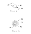
- FIG. 3 is a schematic side elevational view of a service entrance plug having a light emitting device in accordance with one embodiment
- FIG. 3 a is a schematic bottom plan view of the service entrance plug having a light emitting device of FIG. 3 ;
- FIG. 4 is a schematic side elevational view of a service entrance plug having a light emitting device in accordance with a second embodiment
- FIG. 4 a is a schematic side exploded view of the service entrance plug having a light emitting device of FIG. 4 a;
- FIG. 5 schematic cross-sectional view of the deteriorated underground water main conduit of FIG. 1 after a rehabilitation lining has been installed therein;
- FIG. 6 is a schematic cross-sectional view of the rehabilitated underground water main conduit of FIG. 5 and a plug detection and drilling robot and camera assembly therein;
- FIG. 7 is a schematic side elevational view of a drilling head of the plug detection and drilling apparatus in accordance with one embodiment.
- FIG. 8 is a schematic top plan view of the drilling head of FIG. 7 .
- FIG. 1 depicts a segment of an underground water main conduit 10 which is in an advance state of deterioration.
- Water main conduit 10 includes multiple holes, cracks or punctures 12 caused by excessive rust, cracks or soil movements, for example, that allow pressurized water to escape from the water main conduit 10 into the soil, generating drops in pressure and considerable waste of treated water.
- Water main conduit 10 includes three service entrances 14 , 16 and 18 linking water main conduit 10 to households or businesses supplying fresh water to the occupants.
- the process of re-lining a segment of underground water main conduit 10 requires that the service entrances 14 , 16 and 18 be plugged prior to re-lining the water main conduit 10 to prevent any resin from seeping into the service entrances and clogging them.
- a plug setting robot 20 connected to a closed circuit camera 22 through a tension cable 24 at a predetermined distance are introduced together into the water main conduit 10 .
- the plug setting robot 20 and the camera 22 are respectively connected to tension cables 27 and 29 which are connected to a pair of winches (not shown) located above ground and operated by a technician.
- the assembly of the plug setting robot 20 and camera 22 is moved back and forth inside the water main conduit 10 by actuated one of the winches which pulls on one of the tension cables 27 and 29 while the other winch offers little resistance.
- the assembly of the plug setting robot 20 and camera 22 is remotely operated by the technician looking at a television monitor (not shown) relaying live images captured by the camera 22 .
- the plug setting robot 20 comprises a main body 25 housing a power unit and actuator for controlling a dispensing head 30 positioned at the front of the plug setting robot 20 .
- the dispensing head 30 which is rotatable about an axis extending in a horizontal direction and movable back and forth in the horizontal direction for precise alignment with one of the service entrances 14 , 16 or 18 .
- the dispensing head 30 is also movable in the radial direction to press a plug 32 into the service entrances.
- On top of the camera 22 is a magazine 28 housing a series of plugs 32 aligned so that they may be retrieved one by one by the dispensing head 30 .
- the plug setting robot 20 and the camera 22 are mounted on low friction pads 26 such that they can slide onto the bottom surface of the inside wall of the water main conduit 10 .
- the technician looking at a television monitor, moves the plug setting robot 20 to align the dispensing head 30 with one of the service entrances 14 , 16 or 18 .
- the dispensing head 30 is then moved forward to retrieve a plug 32 or 33 from the magazine 28 located on top of the camera 22 and returned to its position in line with the service entrance 16 as illustrated FIG. 2 . Minute adjustments are made in the radial direction by the technician viewing the alignment through his monitor and then the plug 32 or 33 is inserted and pressed into the service entrance 14 by the dispensing head 30 moving towards the service entrance 16 .
- the dispensing head 30 is then retrieved and the technician moves the assembly of the plug setting robot 20 and camera 22 by actuating the winches to align the dispensing head 30 with another service entrance and the cycle is repeated until all the service entrances 14 , 16 or 18 are plugged.
- a first embodiment of the plug 32 includes of a conical hollowed body 34 made of a soft plastic surrounded by a series of flexible winglets 36 adapted to bend when plug 32 is inserted into the service entrance in order to efficiently seal the service entrance.
- the body 34 has first and second ends, wherein the smaller diameter first end is adapted to be inserted into a service entrance and the larger diameter second end is adapted to be visually seen within the underground water conduit.
- the bottom winglet 38 disposed on the second end, has a larger diameter than the flexible winglets 36 , is marginally thicker than flexible winglets 36 and is designed to rest on the edge or perimeter of the service entrance.
- the bottom winglet 38 includes an antenna coil 40 connected to a light emitter 42 located exactly in the center of the winglet 38 .
- the antenna coil 40 is adapted to generate a small electrical current when subjected to an electromagnetic field that will turn on the light emitter 42 .
- a second embodiment of a plug consisting of a two-piece plug 33 which also includes of a conical hollowed body 34 made of a soft plastic surrounded by a series of flexible winglets 36 adapted to bend when the hollowed body 34 is inserted into the service entrance in order to efficiently seal the service entrance.
- the body 34 has first and second ends, wherein the smaller diameter first end is adapted to be inserted into a service entrance and the larger diameter second end is adapted to be visually seen within the underground water conduit.
- the body 34 includes, in its second end, a receptacle winglet 37 having a larger diameter than the flexible winglets 36 designed to rest on the edge or perimeter of the service entrance.
- the receptacle winglet 37 extends inwardly to define an annular lip 39 adapted to hold a cap 41 which is snapped into the annular lip 39 of the receptacle winglet 37 as shown in the exploded view of FIG. 4 a by the dotted arrow.
- the snap-on cap 41 includes a groove 43 which secures the snap-on cap 41 to the annular lip 39 of the receptacle winglet 37 .
- the antenna coil 40 and light emitter 42 shown in FIG. 3 a are embedded in the snap-on cap 41 .
- the installation of the two-piece plug 33 into the service entrances 14 , 16 and 18 may be a one step process in which the assembled two-piece plug 33 including the cap 41 is inserted and pressed into the service entrances by the plug setting robot 20 as previously described, or a two step process in which the body 34 of the two-piece plug 33 is first inserted and pressed into a service entrance by the plug setting robot 20 and then the plug setting robot 20 retrieves a cap 41 including the light emitter 42 from a second a magazine (not shown) housing a series of caps 41 which it inserts into the internal groove 39 of the receptacle winglet 37 of the body 34 previously inserted and pressed into the service entrance.
- a tubular membrane 50 comprising of a pair of concentric circular weave polyester fiber hoses impregnated with epoxy resin is introduced inside the water main conduit 10 .
- the tubular membrane is cooked with hot water under pressure such that the tubular membrane 50 adheres to the inner wall of the water main conduit 10 .
- the resin migrates into the circular weave polyester fibre hoses and renders the tubular membrane 50 semi transparent when the resin has cured. As illustrated in FIG.
- the service entrances 14 , 16 and 18 must be located and the plugs 32 or 33 drilled out in order to re-open the service entrances 14 , 16 and 18 to supply water to the residences or businesses linked to the water main conduit 10 through the service entrances 14 , 16 and 18 .
- a drilling robot 60 connected to a closed circuit camera 22 and a generator 61 are introduced together into the tubular membrane 50 of the water main conduit 10 as illustrated in FIG. 6 .
- the drilling robot 60 , the camera 22 and the generator 61 are connected together as an assembly through tension cables 24 .
- the drilling robot 60 and the generator 61 are respectively connected to tension cables 27 and 29 which are connected to a pair of winches (not shown) located above ground and operated by a technician.
- the assembly of the drilling robot 60 , the camera 22 and the generator 61 is moved back and forth inside the water main conduit 10 by actuated one of the winches which pulls on one of the tension cables 27 and 29 while the other winch offers little resistance.
- the drilling robot 60 and the generator 61 are mounted on low friction pads 64 such that they can slide on the inside of the tubular membrane 50 within the water main conduit 10 .
- the assembly is remotely operated by the technician looking at a television monitor (not shown) relaying live images captured by the camera 22 .
- the drilling robot 60 comprises a main body 62 housing a power unit and actuator for controlling a drilling head 66 positioned at the front of the drilling robot 60 .
- the drilling head 66 includes a drill bit 68 extending perpendicular to main body 62 and the longitudinal axis of the water main conduit 10 .
- the drilling head 66 is rotatable about an axis extending in a horizontal direction and also movable back and forth along the same axis such that the technician is able to precisely align the drill bit 68 with service entrances located in any position around the circumference of the water main conduit 10 .
- a coil inductor 70 is mounted on the drilling head 66 .
- the winding of the coil inductor 70 is concentric with the axis of the drill bit 68 and preferably oval shaped as illustrated in FIG. 8 in order to provide a wider sweep than a regular round shape.
- the generator 61 is electrically connected directly to the coil inductor 70 through an electrical wire 72 to provide the required electrical current to the coil inductor 70 .
- the coil inductor 70 When an electrical current flows through the coil inductor 70 , the coil inductor 70 generates an electromagnetic field.
- the drilling robot 60 is moved inside the water main conduit 10 by the technician into an area where one of the service entrances 14 , 16 , or 18 was plugged by a plug 32 or 33 .
- the technician then activates the coil inductor 70 to generate an electromagnetic field.
- the electromagnetic field generated by the coil inductor 70 is in the vicinity of a plug 32 or 33
- the antenna coil 40 of the plug 32 or 33 generates a small electrical current that turn on the light emitter 42 .
- the semi transparent characteristic of the tubular membrane 50 allows the light emitted by the light emitter 42 to pass through the tubular membrane 50 such that the light can be seen by the technician through the camera 22 positioned directly in front of the drilling head 66 .
- the light emitted is preferably red and flashing for ease of detection.
- the technician is able, through the camera 22 , to visually align the end of the drill bit 68 with the flashing red light by moving the drilling robot 60 back and forth, by rotating the drilling head 66 , and moving the drilling head 66 up and down to be as close as possible to the surface of the tubular membrane 50 and to the flashing red light such that the end of the drill bit 68 is precisely aligned with the plug 32 located behind the tubular membrane 50 . Since the light emitter 42 is exactly in the center of the plug 32 or 33 as previously described, the alignment of the end of the drill bit 68 with the flashing red light aligns the drill bit 68 with the center of the plug 32 or 33 and therefore the center of the service entrance 14 .
- the technician actuates the drill bit 68 and proceeds with drilling out the plug 32 or 33 by moving the drilling head 66 through the tubular membrane 50 and through the plug 32 or 33 located behind the tubular membrane 50 far enough to completely drill out the plug 32 or 33 .
- the drilling head 66 is then retrieved and the drilling robot 60 is moved into an area where another of the service entrances 14 , 16 , or 18 was plugged by a plug 32 or 33 and the cycle of detection, alignment and drilling is repeated until all the plugs 32 or 33 have been drilled out and all the service entrances 14 , 16 and 18 reopened.
- the combination of the tight emitter 42 positioned at the center of the plug 32 or 33 responsive to the electromagnetic field generated by the coil inductor 70 enables the technician to visually align the drill bit 68 with the center of the plug 32 or 33 as opposed to relying on some other signals which has the beneficial effect of accelerating the drilling process and therefore accelerating the reopening of the water main conduit 10 after rehabilitation.
Abstract
Description
Claims (8)
Priority Applications (1)
| Application Number | Priority Date | Filing Date | Title |
|---|---|---|---|
| US14/489,510 US9410654B2 (en) | 2012-09-20 | 2014-09-18 | Apparatus for rehabilitating an underground water conduit and detecting and drilling a service entrance in the conduit |
Applications Claiming Priority (2)
| Application Number | Priority Date | Filing Date | Title |
|---|---|---|---|
| US13/623,332 US8864418B2 (en) | 2012-09-20 | 2012-09-20 | Method and apparatus for rehabilitating an underground water conduit and detecting and drilling a service entrance in the conduit |
| US14/489,510 US9410654B2 (en) | 2012-09-20 | 2014-09-18 | Apparatus for rehabilitating an underground water conduit and detecting and drilling a service entrance in the conduit |
Related Parent Applications (1)
| Application Number | Title | Priority Date | Filing Date |
|---|---|---|---|
| US13/623,332 Division US8864418B2 (en) | 2012-09-20 | 2012-09-20 | Method and apparatus for rehabilitating an underground water conduit and detecting and drilling a service entrance in the conduit |
Publications (3)
| Publication Number | Publication Date |
|---|---|
| US20150069060A1 US20150069060A1 (en) | 2015-03-12 |
| US20160069500A9 US20160069500A9 (en) | 2016-03-10 |
| US9410654B2 true US9410654B2 (en) | 2016-08-09 |
Family
ID=50274634
Family Applications (2)
| Application Number | Title | Priority Date | Filing Date |
|---|---|---|---|
| US13/623,332 Active 2033-02-20 US8864418B2 (en) | 2012-09-20 | 2012-09-20 | Method and apparatus for rehabilitating an underground water conduit and detecting and drilling a service entrance in the conduit |
| US14/489,510 Active 2033-03-13 US9410654B2 (en) | 2012-09-20 | 2014-09-18 | Apparatus for rehabilitating an underground water conduit and detecting and drilling a service entrance in the conduit |
Family Applications Before (1)
| Application Number | Title | Priority Date | Filing Date |
|---|---|---|---|
| US13/623,332 Active 2033-02-20 US8864418B2 (en) | 2012-09-20 | 2012-09-20 | Method and apparatus for rehabilitating an underground water conduit and detecting and drilling a service entrance in the conduit |
Country Status (2)
| Country | Link |
|---|---|
| US (2) | US8864418B2 (en) |
| CA (1) | CA2791746C (en) |
Cited By (3)
| Publication number | Priority date | Publication date | Assignee | Title |
|---|---|---|---|---|
| US11079055B2 (en) | 2018-10-30 | 2021-08-03 | Ina Acquisition Corp. | Fitting for connecting a main pipe liner to a branch conduit |
| US11391407B2 (en) | 2018-11-30 | 2022-07-19 | Ina Acquisition Corp. | Methods, systems, and apparatus for use in main pipes connected to branch conduit |
| US11774025B2 (en) | 2018-10-30 | 2023-10-03 | Ina Acquisition Corp. | Fitting for connecting a main pipe liner to a branch conduit |
Families Citing this family (4)
| Publication number | Priority date | Publication date | Assignee | Title |
|---|---|---|---|---|
| JP6596488B2 (en) * | 2015-04-07 | 2019-10-23 | 株式会社湘南合成樹脂製作所 | Drilling device and drilling method |
| US9927059B2 (en) | 2015-10-14 | 2018-03-27 | Ulc Robotics, Inc. | System and method for pipe insertion in a pipeline |
| US20180328531A1 (en) * | 2017-05-10 | 2018-11-15 | Sipp Technologies, Llc | Plugging Apparatus, System and Method for Pipe Lining Applications |
| CN107560656A (en) * | 2017-09-03 | 2018-01-09 | 中信重工开诚智能装备有限公司 | It is a kind of to detect and position the system and detection method of well lid opening |
Citations (31)
| Publication number | Priority date | Publication date | Assignee | Title |
|---|---|---|---|---|
| US2663451A (en) * | 1951-10-10 | 1953-12-22 | Chandler P Yarnall | Closure plug |
| US2878342A (en) * | 1955-03-21 | 1959-03-17 | Lisle Corp | Magnetic chip detector |
| US3753091A (en) | 1972-04-10 | 1973-08-14 | Submarine Pipeline Technology | Method and device for detecting faults in non-conductive coatings on under water pipelines |
| US3758050A (en) * | 1969-11-25 | 1973-09-11 | R Watts | Photo inspection pod assembly for pipelines |
| US4061965A (en) | 1976-05-24 | 1977-12-06 | Mobil Oil Corporation | Method and apparatus for monitoring a cathodically protected corrodible hollow member |
| US4310797A (en) * | 1978-09-21 | 1982-01-12 | Butler Richard A | Stud detector using a magnetically actuated switch with magnetic biasing |
| US4402641A (en) * | 1980-04-17 | 1983-09-06 | Itw Ateco Gmbh | Self centering fastener |
| US4951758A (en) | 1988-01-27 | 1990-08-28 | Sekisui Kagaku Kogo Kabushiki Kaisha | Method of drilling a branch line aperture after internal lining of a pipeline and a water plug used in the method |
| US5054512A (en) * | 1990-04-24 | 1991-10-08 | Jiles Stephen L | Insertion assembly for a pipe stopper |
| US5151657A (en) * | 1989-05-24 | 1992-09-29 | Tashjian Michael D | Underground pipe locating apparatus |
| US5417112A (en) * | 1993-01-11 | 1995-05-23 | Tdw Delaware, Inc. | Apparatus for indicating the passage of a pig moving within an underground pipeline |
| US5497807A (en) | 1993-03-10 | 1996-03-12 | British Gas Plc | Apparatus for introducing sealant into a clearance between an existing pipe and a replacement pipe |
| US5558130A (en) * | 1991-12-18 | 1996-09-24 | Synthotech Marine Limited | Pipe stopper having a guide member to assist in guiding the stopper around a bend in a pipe |
| US6223776B1 (en) * | 1999-05-26 | 2001-05-01 | Ut-Battelle, Llc | Guidable pipe plug |
| US6494463B1 (en) * | 2000-11-06 | 2002-12-17 | Kurt J. Rank | Plug for sealing more than one size of hole |
| US20080278154A1 (en) * | 2005-12-23 | 2008-11-13 | Reiner Krapf | Device for Determining an Object, in Particular a Locating Device or Material Identification Device |
| US20080314468A1 (en) * | 2007-06-22 | 2008-12-25 | Jon Houghton | Cap or Plate With Electronic Or Magnetic Marker |
| US20090095211A1 (en) * | 2007-10-11 | 2009-04-16 | Tubemaster, Inc. | Device and method for indicating the condition of tubes on a tubesheet |
| US7591901B1 (en) | 2009-06-02 | 2009-09-22 | Kent Weisenberg | Method and apparatus of lining pipes with environmentally compatible impervious membrane |
| US20090272452A1 (en) | 2008-02-01 | 2009-11-05 | Cain John A | Systems and methods for locating and restoring service lines in pipeline rehabilitation |
| US20100078895A1 (en) * | 2008-08-20 | 2010-04-01 | Anthony Sudano | Device and method for the plugging of services in conduits |
| US20100090700A1 (en) * | 2008-10-02 | 2010-04-15 | Certusview Technologies, Llc | Methods and apparatus for displaying an electronic rendering of a locate operation based on an electronic record of locate information |
| US20100307604A1 (en) * | 2009-06-03 | 2010-12-09 | Mueller International, Inc. | Resilient plug apparatus and method of use |
| US8231629B2 (en) | 2006-06-29 | 2012-07-31 | L.R.S. Ortho Ltd. | System and method for locating of distal holes of an intramedullary nail |
| US8264226B1 (en) * | 2006-07-06 | 2012-09-11 | Seektech, Inc. | System and method for locating buried pipes and cables with a man portable locator and a transmitter in a mesh network |
| US20130127470A1 (en) * | 2011-05-11 | 2013-05-23 | Seektech, Inc. | Buried object locator apparatus and systems |
| US20130156506A1 (en) | 2011-12-20 | 2013-06-20 | Oliner System Llc | Method for Renewal or Rehabilitation of Water Supply Pipelines and Plug Arrangement for use in Said Method |
| US20130157713A1 (en) * | 2007-11-29 | 2013-06-20 | Larry G. Stolarczyk | Cap-lamp and communications support system |
| US20140152300A1 (en) * | 2012-12-03 | 2014-06-05 | Horward V. KEITH, III | Stud magnet device |
| US20140175100A1 (en) * | 2012-07-17 | 2014-06-26 | Forespar Products Corp. | Configurable plug to stop or slow the flow of a fluid or gas or flowable material either inward or outward through an opening |
| US8766638B2 (en) * | 2008-10-02 | 2014-07-01 | Certusview Technologies, Llc | Locate apparatus with location tracking system for receiving environmental information regarding underground facility marking operations, and associated methods and systems |
-
2012
- 2012-09-20 US US13/623,332 patent/US8864418B2/en active Active
- 2012-10-10 CA CA2791746A patent/CA2791746C/en active Active
-
2014
- 2014-09-18 US US14/489,510 patent/US9410654B2/en active Active
Patent Citations (31)
| Publication number | Priority date | Publication date | Assignee | Title |
|---|---|---|---|---|
| US2663451A (en) * | 1951-10-10 | 1953-12-22 | Chandler P Yarnall | Closure plug |
| US2878342A (en) * | 1955-03-21 | 1959-03-17 | Lisle Corp | Magnetic chip detector |
| US3758050A (en) * | 1969-11-25 | 1973-09-11 | R Watts | Photo inspection pod assembly for pipelines |
| US3753091A (en) | 1972-04-10 | 1973-08-14 | Submarine Pipeline Technology | Method and device for detecting faults in non-conductive coatings on under water pipelines |
| US4061965A (en) | 1976-05-24 | 1977-12-06 | Mobil Oil Corporation | Method and apparatus for monitoring a cathodically protected corrodible hollow member |
| US4310797A (en) * | 1978-09-21 | 1982-01-12 | Butler Richard A | Stud detector using a magnetically actuated switch with magnetic biasing |
| US4402641A (en) * | 1980-04-17 | 1983-09-06 | Itw Ateco Gmbh | Self centering fastener |
| US4951758A (en) | 1988-01-27 | 1990-08-28 | Sekisui Kagaku Kogo Kabushiki Kaisha | Method of drilling a branch line aperture after internal lining of a pipeline and a water plug used in the method |
| US5151657A (en) * | 1989-05-24 | 1992-09-29 | Tashjian Michael D | Underground pipe locating apparatus |
| US5054512A (en) * | 1990-04-24 | 1991-10-08 | Jiles Stephen L | Insertion assembly for a pipe stopper |
| US5558130A (en) * | 1991-12-18 | 1996-09-24 | Synthotech Marine Limited | Pipe stopper having a guide member to assist in guiding the stopper around a bend in a pipe |
| US5417112A (en) * | 1993-01-11 | 1995-05-23 | Tdw Delaware, Inc. | Apparatus for indicating the passage of a pig moving within an underground pipeline |
| US5497807A (en) | 1993-03-10 | 1996-03-12 | British Gas Plc | Apparatus for introducing sealant into a clearance between an existing pipe and a replacement pipe |
| US6223776B1 (en) * | 1999-05-26 | 2001-05-01 | Ut-Battelle, Llc | Guidable pipe plug |
| US6494463B1 (en) * | 2000-11-06 | 2002-12-17 | Kurt J. Rank | Plug for sealing more than one size of hole |
| US20080278154A1 (en) * | 2005-12-23 | 2008-11-13 | Reiner Krapf | Device for Determining an Object, in Particular a Locating Device or Material Identification Device |
| US8231629B2 (en) | 2006-06-29 | 2012-07-31 | L.R.S. Ortho Ltd. | System and method for locating of distal holes of an intramedullary nail |
| US8264226B1 (en) * | 2006-07-06 | 2012-09-11 | Seektech, Inc. | System and method for locating buried pipes and cables with a man portable locator and a transmitter in a mesh network |
| US20080314468A1 (en) * | 2007-06-22 | 2008-12-25 | Jon Houghton | Cap or Plate With Electronic Or Magnetic Marker |
| US20090095211A1 (en) * | 2007-10-11 | 2009-04-16 | Tubemaster, Inc. | Device and method for indicating the condition of tubes on a tubesheet |
| US20130157713A1 (en) * | 2007-11-29 | 2013-06-20 | Larry G. Stolarczyk | Cap-lamp and communications support system |
| US20090272452A1 (en) | 2008-02-01 | 2009-11-05 | Cain John A | Systems and methods for locating and restoring service lines in pipeline rehabilitation |
| US20100078895A1 (en) * | 2008-08-20 | 2010-04-01 | Anthony Sudano | Device and method for the plugging of services in conduits |
| US20100090700A1 (en) * | 2008-10-02 | 2010-04-15 | Certusview Technologies, Llc | Methods and apparatus for displaying an electronic rendering of a locate operation based on an electronic record of locate information |
| US8766638B2 (en) * | 2008-10-02 | 2014-07-01 | Certusview Technologies, Llc | Locate apparatus with location tracking system for receiving environmental information regarding underground facility marking operations, and associated methods and systems |
| US7591901B1 (en) | 2009-06-02 | 2009-09-22 | Kent Weisenberg | Method and apparatus of lining pipes with environmentally compatible impervious membrane |
| US20100307604A1 (en) * | 2009-06-03 | 2010-12-09 | Mueller International, Inc. | Resilient plug apparatus and method of use |
| US20130127470A1 (en) * | 2011-05-11 | 2013-05-23 | Seektech, Inc. | Buried object locator apparatus and systems |
| US20130156506A1 (en) | 2011-12-20 | 2013-06-20 | Oliner System Llc | Method for Renewal or Rehabilitation of Water Supply Pipelines and Plug Arrangement for use in Said Method |
| US20140175100A1 (en) * | 2012-07-17 | 2014-06-26 | Forespar Products Corp. | Configurable plug to stop or slow the flow of a fluid or gas or flowable material either inward or outward through an opening |
| US20140152300A1 (en) * | 2012-12-03 | 2014-06-05 | Horward V. KEITH, III | Stud magnet device |
Cited By (4)
| Publication number | Priority date | Publication date | Assignee | Title |
|---|---|---|---|---|
| US11079055B2 (en) | 2018-10-30 | 2021-08-03 | Ina Acquisition Corp. | Fitting for connecting a main pipe liner to a branch conduit |
| US11774025B2 (en) | 2018-10-30 | 2023-10-03 | Ina Acquisition Corp. | Fitting for connecting a main pipe liner to a branch conduit |
| US11391407B2 (en) | 2018-11-30 | 2022-07-19 | Ina Acquisition Corp. | Methods, systems, and apparatus for use in main pipes connected to branch conduit |
| US11828400B2 (en) | 2018-11-30 | 2023-11-28 | Ina Acquisition Corp. | Methods, systems, and apparatus for use in main pipes connected to branch conduit |
Also Published As
| Publication number | Publication date |
|---|---|
| US20140079488A1 (en) | 2014-03-20 |
| US20160069500A9 (en) | 2016-03-10 |
| US8864418B2 (en) | 2014-10-21 |
| CA2791746A1 (en) | 2014-03-20 |
| CA2791746C (en) | 2020-04-14 |
| US20150069060A1 (en) | 2015-03-12 |
Similar Documents
| Publication | Publication Date | Title |
|---|---|---|
| US9410654B2 (en) | Apparatus for rehabilitating an underground water conduit and detecting and drilling a service entrance in the conduit | |
| CA2791772C (en) | Aircraft equipped with a buoyancy system for a rotating element | |
| US7707704B2 (en) | Sealing methods | |
| US4819721A (en) | Remotely controlled articulatable hydraulic cutter apparatus | |
| US4434115A (en) | Method for remote lining of side connections | |
| US5566719A (en) | Method for lining a branch pipe of an underground pipe | |
| US6056017A (en) | Pipe lining method | |
| KR101886152B1 (en) | Apparatus and method for inspecting pipe | |
| US20050139263A1 (en) | Remote tapping method and system for internally tapping a conduit | |
| US5498389A (en) | Method and apparatus for lining a branch pipe | |
| EP0487179B1 (en) | Method for water leakage prevention in pipeline | |
| US20240027013A1 (en) | An apparatus for curing a liner | |
| US20110293767A1 (en) | Method and system for curing pipe liners using microwave energy | |
| EP0891857A2 (en) | Device for confirming the position of branch pipe opening and pipe lining method using the device | |
| US10658824B2 (en) | Method and apparatus for removing a cable core from a cable sheath | |
| US20230279982A1 (en) | Systems and methods for lining a pipe with a lighted liner or bladder | |
| WO1992002755A1 (en) | Inserting linings into pipes | |
| DE59904235D1 (en) | METHOD FOR CREATING AN ABOVE GROUND PIPELINE AND CORRESPONDING HOSE | |
| EP4314620A1 (en) | Lining hose, curing device, system, and method for renovating conduits without using trenches | |
| JP2002262424A (en) | Manufacturing method for installation cable and cable- conducting method for installation cable | |
| KR20200068334A (en) | Apparatus and method for partially repairing pipe of injection liner formation type | |
| JP2004316304A (en) | Cutting tool | |
| GB2247062A (en) | Sealing of pipes | |
| JPH10133079A (en) | Method for laying optical cable in laid pipe | |
| KR19990021763U (en) | Wire buried device in underground pipeline |
Legal Events
| Date | Code | Title | Description |
|---|---|---|---|
| AS | Assignment |
Owner name: SANEXEN ENVIRONMENTAL SERVICES INC., CANADA Free format text: ASSIGNMENT OF ASSIGNORS INTEREST;ASSIGNOR:GAGNON, GILLES;REEL/FRAME:033763/0765 Effective date: 20120911 Owner name: SANEXEN ENVIRONMENTAL SERVICES INC., CANADA Free format text: ASSIGNMENT OF ASSIGNORS INTEREST;ASSIGNOR:DLG SENC;REEL/FRAME:033763/0807 Effective date: 20120911 Owner name: DLG SENC, CANADA Free format text: ASSIGNMENT OF ASSIGNORS INTEREST;ASSIGNORS:GERVAIS-DUMONT, CHARLES;DUFF, JASON;LANNEVILLE-VEZINA, PIERRE-HUGUES;REEL/FRAME:033763/0798 Effective date: 20120911 |
|
| FEPP | Fee payment procedure |
Free format text: PAT HOLDER NO LONGER CLAIMS SMALL ENTITY STATUS, ENTITY STATUS SET TO UNDISCOUNTED (ORIGINAL EVENT CODE: STOL); ENTITY STATUS OF PATENT OWNER: LARGE ENTITY |
|
| STCF | Information on status: patent grant |
Free format text: PATENTED CASE |
|
| SULP | Surcharge for late payment | ||
| MAFP | Maintenance fee payment |
Free format text: PAYMENT OF MAINTENANCE FEE, 4TH YEAR, LARGE ENTITY (ORIGINAL EVENT CODE: M1551); ENTITY STATUS OF PATENT OWNER: LARGE ENTITY Year of fee payment: 4 |
|
| MAFP | Maintenance fee payment |
Free format text: PAYMENT OF MAINTENANCE FEE, 8TH YEAR, LARGE ENTITY (ORIGINAL EVENT CODE: M1552); ENTITY STATUS OF PATENT OWNER: LARGE ENTITY Year of fee payment: 8 |
|
| AS | Assignment |
Owner name: THE TORONTO-DOMINION BANK, CANADA Free format text: SECURITY INTEREST;ASSIGNORS:SANEXEN SERVICES ENVIRONNEMENTAUX INC./SANEXEN ENVIRONMENTAL SERVICES INC.;NIEDNER INC.;REEL/FRAME:066491/0709 Effective date: 20240215 |